Transformer fault-recovery inrush currents in MMC-HVDC systems and mitigation strategies
Upload
nguyennhanCategory
view
223download
0
Protection and Control ofModern Power Systems
Yao et al. Protection and Control of Modern Power Systems (2016) 1:8 DOI 10.1186/s41601-016-0022-0
ORIGINAL RESEARCH Open Access
Research on fault diagnosis for MMC-HVDCSystems
Zhiqing Yao1*, Qun Zhang2, Peng Chen2 and Qian Zhao2Abstract
Introduction: With the development of flexible HVDC technology, the fault diagnosis of MMC-HVDC becomes anew research direction.Based on the fault diagnosis theory, this paper proposes a robust fault diagnosis method to study the faultdiagnosis problem of MMC-HVDC systems.
Methods: By optimizing the gain matrix in the fault observer, fault detection with good sensitivity and robustnessto disturbance is achieved. In the MMC-HVDC system, because of the inherently uncertain system and the presenceof various random disturbances, the study of robust fault diagnosis method is particularly important.
Results: Simulation studies during various AC faults have been carried out based on a 61-level MMC-HVDCmathematical model. The results validate the feasibility and effectiveness of the proposed fault diagnosis method.
Conclusions: So this fault diagnosis method can be further applied to the actual project, to quickly achieve systemfault diagnosis and accurately complete fault identification.
Keywords: Fault diagnosis, MMC-HVDC, Robust, State observer, Residual state equation
IntroductionIn recent years, due to the increased size and complexity ofcontrol systems, fault diagnosis becomes particularly im-portant, especially in power systems [1]. For instance, if linefaults are not quickly detected and isolated, they can causesystem failure or even lead to disastrous consequences [2].Currently, there are many fault diagnosis methods, suchas the diagnostic filter method, parameter identificationmethod, expert system, artificial neural network etc. [3–5].Although these methods can effectively detect failures in thesystem, they cannot precisely estimate these fault signals.This paper proposes a fault diagnosis method based
on full dimension state observer for flexible HVDC sys-tem. State estimation is carried out using the mathemat-ical model of a three-phase 61-level modular multilevelconverter (MMC) based HVDC (MMC-HVDC) systemand the full dimension state observer. Residual stateequation is established and is combined with the systemoutput and system phasor. By optimizing the gain matrixin fault observer, the robustness of the fault detection is
* Correspondence: [email protected] KETOP Electrical Research Institute, Xuchang, ChinaFull list of author information is available at the end of the article
© 2016 The Author(s). Open Access This articleInternational License (http://creativecommons.oreproduction in any medium, provided you givthe Creative Commons license, and indicate if
investigated. In the MMC-HVDC system, because thesystem is inherently uncertain and there are various ran-dom disturbances, the study of robust fault diagnosismethod is particularly important.
MethodsModel of MMC-HVDCA three-phase MMC topology is shown in Fig. 1 [6–9].According to KCL, the three-phase current can beexpressed as
ia ¼ ipa þ inaib ¼ ipb þ inbic ¼ ipc þ inc
8<: ð1Þ
For three single-phase units, applying KVL to theupper and lower arms yields:
ua−Udc
2−upa
� �¼ 2L
dipadt
þ 2Ripa
ub−Udc
2−upb
� �¼ 2L
dipbdt
þ 2Ripb
uc−Udc
2−upc
� �¼ 2L
dipcdt
þ 2Ripc
8>>>>>>><>>>>>>>:
ð2Þ
is distributed under the terms of the Creative Commons Attribution 4.0rg/licenses/by/4.0/), which permits unrestricted use, distribution, ande appropriate credit to the original author(s) and the source, provide a link tochanges were made.

Fig. 1 Three phase MMC topology
Yao et al. Protection and Control of Modern Power Systems (2016) 1:8 Page 2 of 7
ua− una−Udc
2
� �¼ 2L
dinadt
þ 2Rina
ub− unb−Udc
2
� �¼ 2L
dinbdt
þ 2Rinb
uc− unc−Udc
2
� �¼ 2L
dincdt
þ 2Rinc
8>>>>>>><>>>>>>>:
ð3Þ
In the above equations, 2L and 2R denote the equiva-lent arm inductance and resistance, respectively. AddingEqs. (2) and (3) leads
ua− una−upa� �
=2 ¼ Ldiadt
þ Ria
ua− unb−upb� �
=2 ¼ Ldibdt
þ Rib
uc− unc−upc� �
=2 ¼ Ldicdt
þ Ric
8>>>>>><>>>>>>:
ð4Þ
According to Eq. (4), the time domain mathe-matic model of a MMC in abc coordinate is givenby [10, 11].
dia tð Þdt
¼ −RLia tð Þ þ 1
Lua tð Þ− una tð Þ−upa tð Þ� �
=2� �
dib tð Þdt
¼ −RLib tð Þ þ 1
Lub tð Þ− unb tð Þ−upb tð Þ� �
=2� �
dic tð Þdt
¼ −RLic tð Þ þ 1
Luc tð Þ− unc tð Þ−upc tð Þ� �
=2� �
8>>>>>><>>>>>>:
ð5Þ
Written Eq. (5) in phasor form yields
ddt
iaibic
24
35 ¼
−RL
0 0
0 −RL
0
0 0 −RL
266664
377775
iaibic
24
35
þ−
12L
12L
0 0 0 0
0 0 −12L
12L
0 0
0 0 0 0 −12L
12L
266664
377775
unaupaunbupbuncupc
26666664
37777775
þ
1L
0 0
01L
0
0 01L
266664
377775
uaubuc
24
35
ð6Þ
Considering the uncertainty, external disturbances andsystem faults, the Eq. (6) can be written as follows
:x tð Þ ¼ Ax tð Þ þ Bu tð Þ þ h tð Þ þ Δ tð Þ þ Bf f tð Þy tð Þ ¼ Cx tð Þ þDM tð Þ
�ð7Þ
i2 3 una
upa
266
377 −
RL
0 026
37
where x tð Þ ¼a
ibic
4 5, u tð Þ ¼ unbupbuncupc
6666477775, A ¼ 0 −
RL
0
0 0 −RL
66647775,
−12L
12L
0 0 0 026
37 1
L0 0
26
372 3
B ¼ 0 0 −12L
12L
0 0
0 0 0 0 −12L
12L
66647775, h tð Þ ¼ 0
1L
0
0 01L
66647775
uaubuc
4 5.
In Eq. (7), Δ(t) represents uncertainty and external dis-turbances generated during the actual modeling process.f(t) represents the system faults which are required to

Yao et al. Protection and Control of Modern Power Systems (2016) 1:8 Page 3 of 7
detect and identify. M(t) is measurement noise intro-duced by the measurement system. Bf, C and D areknown matrices with appropriate dimensions. y(t) is thesystem output. If Ω(t) is used to represent Δ(t) + h(t),Eq. (7) can be written as follows.
:x tð Þ ¼ Ax tð Þ þ Bu tð Þ þΩ tð Þ þ Bf f tð Þy tð Þ ¼ Cx tð Þ þDM tð Þ
�ð8Þ
For further analysis, the following assumptions aremade:
1) Uncertainties in the system are norm-bounded, thatis ‖Δ(t)‖ ≤VΔ.
2) System matrix pair (A, C) is observable.3) Uncertainties in the system meet the condition
‖Ω(t)‖ ≤ γ‖x(t)‖ ≤VΩ.4) The M(t) in the system is norm-bounded, that is
‖M(t)‖ ≤ VM.5) The initial state of the system is zero.
Design of full dimension state observerFault diagnosis is carried out by full dimension stateobserver based on the state equation of flexibleHVDC system [12–14]. It can be seen from Eq. (8)that Ω(t) contains the system uncertainties and exter-nal disturbance, and the grid voltage ua, ub, uc, whichcan be regarded as unknown nonlinear perturbationterm.A state observer is established according to Eq. (8):
:x tð Þ ¼ Ax tð Þ þ Bu tð Þ þH y tð Þ−y tð Þð Þy tð Þ ¼ Cx tð Þ
ð9ÞIn Eq. (9), H is a gain matrix to be designed. Accord-
ing to Eqs. (8) and (9), system residual state equation isgiven by:
:x tð Þ− :
x tð Þ ¼ A−ΗCð Þ x tð Þ−x tð Þð Þ þΩ tð Þ þ Bf f tð Þ−HDM tð Þy tð Þ−y tð Þ ¼ C x tð Þ−x tð Þð Þ þDM tð Þ
(
ð10ÞIf e tð Þ ¼ x tð Þ−x tð Þ and r(t) = y(t) − ŷ(t), Eq. (10) can be
written as follows:
:e tð Þ ¼ A−HCð Þe tð Þ þΩ tð Þ þ Bf f tð Þ−HDM tð Þr tð Þ ¼ Ce tð Þ þDM tð Þ
�ð11Þ
In the design of the full dimension state observer, theimpact of the fault and external disturbance or uncer-tainties on the residual should be considered. The trans-fer function from system uncertainties and externaldisturbance to residual r(t) is presented by Trd whereasTrf presents the transfer function from system fault toresidual r(t). If the value of ‖Trd‖ is small enough and
the value of ‖Trf‖ is big enough in the design, the de-signed observer will be robust. Therefore, the followingperformance index is used to design the fault diagnosisobserver:
J ¼ Trf
Trdk k ð12Þ
In practical applications, the above performance indexcan be equivalent to the following equation:
r tð Þk k∝≤β d tð Þk k∝; r tð Þk k−≥η f tð Þk k− ð13Þ
Equation (13) can be solved by using multi-objectiveoptimization methods and thus the robust control the-ory will be used to solve the performance optimizationproblem proposed by Eq. (13).
Theorem 1 The system represented by Eq. (8) satisfiesthe assumptions (1)-(5). Optimization index β is givenand satisfies the condition DTD − β2I < 0. In case of nofault in the system, if there are a positive definite sym-metric matrix R and a constant factor ε1 > 0 meeting thefollowing linear matrix inequality:
R A−HCð Þ þ A−HCð ÞTRþ ε−11 RTRþ CTC 0 CTD−RHD0 ε1γ2I 0
DTC− RHDð ÞT 0 DTD−β2I
24
35
ð14Þ
the residual system (11) is asymptotically stable andmeets ‖r(t)‖∝ ≤ β‖d(t)‖∝.
Theorem 2 The system represented by Eq. (8) satisfiesthe assumptions (1)-(5). Optimization index η is givenand satisfies the condition DTD − η2I < 0. In case of nofault in the system, if there are a positive definite sym-metric matrix T and a constant factor η1 > 0 meeting thefollowing linear matrix inequality:
R A−HCð Þ þ A−HCð ÞTRþ η−11 RTRþ CTC 0 −CTDþ RHD0 η1γ
2I 0−DTCþ RHDð ÞT 0 η2I−DTD
24
35
ð15Þ
The residual system (11) is asymptotically stable andmeets ‖r(t)‖− ≥ η‖f(t)‖−.
Theorem 3 The system represented by Eq. (8) satisfiesthe assumptions (1)-(5). Optimization index β > 0, η > 0are given. If there are positive definite symmetric matrixR, T,H, constant factor ε1 < 0 and η1 > 0 meeting the fol-lowing linear matrix inequality:

Fig. 2 Phase-A to ground fault
Yao et al. Protection and Control of Modern Power Systems (2016) 1:8 Page 4 of 7
R A−HCð Þ þ A−HCð ÞTRþ ε−11 RTRþ CTC 0 CTD−RHD0 ε1γ2I 0
DTC− RHDð ÞT 0 DTD−β2I
24
35
ð16Þ
R A−HCð Þ þ A−HCð ÞTRþ η−11 RTRþ CTC 0 −CTDþ RHD0 η1γ
2I 0−DTCþ RHDð ÞT 0 η2I−DTD
24
35
ð17Þ
The residual system (11) is asymptotically stable andmeets ‖r(t)‖∝ ≤ β‖d(t)‖∝ and ‖r(t)‖− ≥ η‖f(t)‖−.The gain matrix H of the full dimension state ob-
server can be obtained from Theorem 3. The designprocess of gain matrix H takes into account the im-pact of system disturbances and uncertainties on theresidual, and the sensitivity of the residual forfaults.
Fig. 3 Residual error curve during phase-A to ground fault
Determination of fault detection thresholdWhen disturbances or uncertainties exist in the system,a fault detection threshold method is usually used to de-termine whether the system has a fault [15–17]. Thissection provides fault detection thresholds calculated ac-cording to the definition of norm.
Theorem 4 The system represented by Eq. (8) satisfiesthe assumptions (1)-(5). If the residual system (11)meets ‖r(t)‖ > (aVΩ + bVM)(t − t0) + cVM, then systemfault is detected,where a ¼ sup
t∈ t0;t½ �CΨ t; sð Þk k , b ¼ sup
t∈ t0;t½ �CΨ t; sð ÞHDk k, c ¼ sup
t∈ t0;t½ �Dk k.
Proof According to the residual state Eq. (11) thefollowing two equations can be derived:
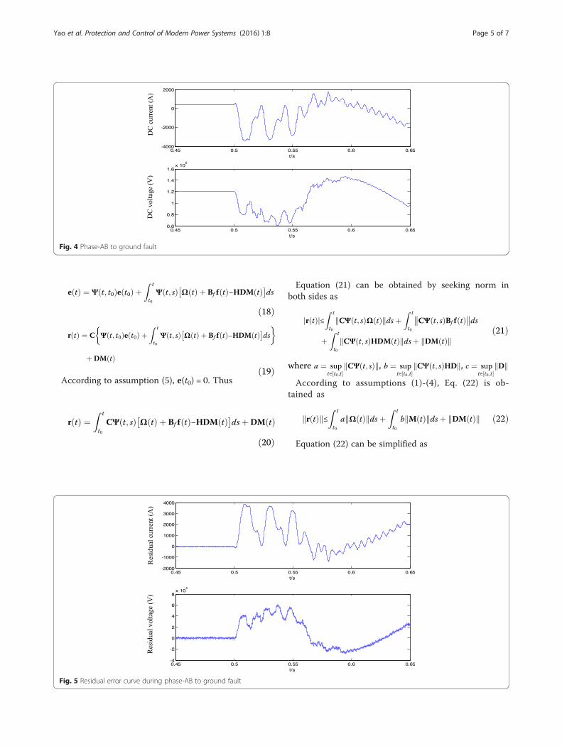
Fig. 4 Phase-AB to ground fault
Yao et al. Protection and Control of Modern Power Systems (2016) 1:8 Page 5 of 7
e tð Þ ¼ Ψ t; t0ð Þe t0ð Þ þZ t
t0
Ψ t; sð Þ Ω tð Þ þ Bf f tð Þ−HDM tð Þ� �ds
ð18Þ
r tð Þ ¼ C Ψ t; t0ð Þe t0ð Þ þZ t
t0
Ψ t; sð Þ Ω tð Þ þ Bf f tð Þ−HDM tð Þ� �ds
� �
þDM tð Þð19Þ
According to assumption (5), e(t0) = 0. Thus
Fig. 5 Residual error curve during phase-AB to ground fault
r tð Þ ¼Z t
t0
CΨ t; sð Þ Ω tð Þ þ Bf f tð Þ−HDM tð Þ� �dsþ DM tð Þ
ð20Þ
Equation (21) can be obtained by seeking norm inboth sides as
r tð Þj j≤Z t
t0
CΨ t; sð ÞΩ tð Þk kdsþZ t
t0
CΨ t; sð ÞBf f tð Þ dsþZ t
t0
CΨ t; sð ÞHDM tð Þk kdsþ DM tð Þk kð21Þ
where a ¼ supt∈ t0;t½ �
CΨ t; sð Þk k, b ¼ supt∈ t0;t½ �
CΨ t; sð ÞHDk k, c ¼ supt∈ t0;t½ �
Dk k
According to assumptions (1)-(4), Eq. (22) is ob-tained as
r tð Þk k≤Z t
t0
a Ω tð Þk kdsþZ t
t0
b M tð Þk kdsþ DM tð Þk k ð22Þ
Equation (22) can be simplified as

Fig. 6 Three phase to ground fault
Yao et al. Protection and Control of Modern Power Systems (2016) 1:8 Page 6 of 7
r tð Þk k≤Z t
t0
aVΩdsþZ t
t0
bVMdsþ cVM
¼ aVΩ t−t0ð Þ þ bVM t−t0ð Þ þ cVM
¼ aVΩ þ bVMð Þ t−t0ð Þ þ cVM
ð23Þ
Proof is done.
ResultsSimulation resultsAccording to the MMC-HVDC system state Eq. (7),common types of fault, e.g. phase A to ground fault,phase-AB to ground fault, three phase to ground faultare simulated based on the 61-level MMC-HVDC sys-tem using Matlab/Simulink and RT-LAB.The rated DC voltage of the system is 120 kV and the
rated active power is 50 MW. The rectifier controls ac-tive power control and the inverter controls the DC volt-age. AC fault is simulated during 0.5 to 0.55 s. The
Fig. 7 Residual error curve during three phase to ground fault
simulation output voltage and current waveforms areshown in Figs. 2, 3, 4, 5, 6 and 7.
Phase-A to ground faultFigure 2 shows the DC bus voltage and current wave-form when the phase-A to ground fault occurs in therectifier side. The fault is introduced at 0.5 s when thesystem is running at steady state. The residual character-istics of the DC bus voltage and current can be calcu-lated by the MMC-HVDC system residual state Eq. (13),as shown in Fig. 3. The baseline reference points of theHVDC fault observer output voltage and current arezero, which can be seen by comparing Figs. 2 and 3.When the system operates normally, taking into accountthe existing uncertainties and various random distur-bances, residual curve should fluctuate within a limitedrange. From Fig. 3 it can be seen that, after a systemfault, the system output curves (the DC bus voltage andcurrent) significantly deviate from zero and their normal

Yao et al. Protection and Control of Modern Power Systems (2016) 1:8 Page 7 of 7
bands. The system’s fault diagnostic threshold can becalculated according to Theorem 4. If the residual wave-form fluctuates within the calculated threshold, it isjudged that the system is operating normally. If the re-sidual waveform exceeds the calculated threshold, a faultis detected and immediate protection action should betaken. Furthermore, the fault identification and fault es-timation can also be studied according to the residualwaveform. As seen from the simulation, when t > 0.52 s,it detects a fault in the system.
Phase-AB to ground faultThe waveforms during phase-AB to ground fault areshown in Fig. 4 where the fault is introduced at 0.5 s. Dueto the existence of various disturbances and uncertaintiesin the system, measurement noise is inevitably introducedwhen measuring system output. The residual voltage andresidual current waveforms are shown in Fig. 5. Accordingto Theorem 4, the fault detection threshold is Jth = 0.136 *104. As seen from the simulation, when t > 0.52 s, the faultis detected.
Three phase to ground faultThe waveforms during three phase to ground fault isshown in Fig. 6. The fault is again introduced at0.5 s. The residual voltage and residual current wave-forms calculated according to residual system stateequation are shown in Fig. 7. According to Theorem4, the fault detection threshold is Jth = 2.62*104. Asseen from the simulation, when t > 0.52 s, the systemfault is detected.
ConclusionsIn this paper, a robust fault diagnosis method is proposedto detect system fault in MMC-HVDC power transmis-sion systems. The advantage of the proposed method isthat the state observer considers the system uncertaintiesand fault sensitivity. Therefore, the proposed method canquickly achieve system fault diagnosis and accuratelycomplete fault identification. The simulation results haveproved the effect of robust fault diagnosis.
Authors’ contributionsZQY analyzed and proposed the robust fault diagnosis method. QZ, PC andQZ completed the simulations on RT-LAB and the written of this paper. ALLthe authors read and approved the final manuscript.
Competing interestsThe authors declare that they have no competing interests.
Author details1Xuchang KETOP Electrical Research Institute, Xuchang, China. 2XJ ElectricCo., Ltd, Xuchang, China.
Received: 13 May 2016 Accepted: 16 May 2016
References1. Zhang, ST, & Hao, JJ. (2012). Fault diagnosis based on multiple-models
particle filter. Control Engineering of China, 19(5), 864–871.2. Song, ZM, Guo, YH, Xun, TS, et al. (2012). Reaserch on HVDC transmission
system fault analysis based on wavelet transform. Power System Protectionand Control, 40(3), 100–104.
3. Bian, L, & Bian, CY. (2014). Review on intelligence fault diagnosis in powernetworks. Power System Protection and Control, 42(3), 146–158.
4. Li, HW, Yang, DS, Sun, YL, et al. (2013). Study review and prospect ofintelligent fault diagnosis technique. Computer Engineering and Design,34(2), 632–637.
5. Wang, JL, Xia, L, Wu, ZG, et al. (2010). State of arts of fault diagnosis ofpower systems. Power System Protection and Control, 38(18), 210–216.
6. Dai, GF, Zhao, D, Lin, PF, et al. (2015). Study of control strategy for activepower filter based on modular multilevel converter. Power System Protectionand Control, 43(8), 74–80.
7. Gnanarathna, UN, Gole, AM, & Jayasinghe, RP. (2011). Efficient modeling ofmodular multilevel HVDC converters (MMC) on electromagnetic transientsimulation programs. IEEE Transactions on Power Delivery, 26(1), 316–324.
8. Peralta, J, Saad, H, Dennetiere, S, et al. (2012). Detailed and averagedmodels for a 401-level MMC-HVDC system. IEEE Transactions on PowerDelivery, 27(3), 1501–1508.
9. Simon, P.T. Simplified dynamic model of a voltage sourced converter withmodular multilevel converter design. IEEE/PES Power Systems Conferenceand Exposition. Seattle, USA, 2009: 1–6
10. Simon, P.T. Modeling the trans bay cable project as voltage-sourcedconverter with modular multilevel converter design. IEEE Power and EnergySociety General Meeting. Michigan, USA, 2011: 1–8
11. Guan, M, & Xu, Z. (2012). Modeling and control of modular multilevelconverter based HVDC system under unbalanced grid conditions. IEEETransactions on Power Electronics, 27(12), 4858–4867.
12. Zhu, QL, Peng, CH, Li, JF, et al. (2012). Fuzzy DTC of PMSM based on fullorder observer. Power Electronics, 46(1), 87–89.
13. Yang, JQ, & Zhu, FL. (2014). Linear-matrix-inequality observer design ofnonlinear systems with unknown input and measurement noisereconstruction. Control Theroy & Applications, 31(4), 538–544.
14. Gao, H, & Cai, XS. (2013). Functional obsever design for a class of nonlinearsystems. Control Theory & Applications, 30(9), 1207–1210.
15. Zhao, Y, Dong, S, & Li, TY. (2010). A new adaptive threshold algorithm topartial discharge processing based on HHT-MDL criterion. Power SystemProtection and Control, 38(5), 45–50.
16. Zhu, XH, Li, YH, Li, N, et al. (2013). Novel observer-based on robust faultdetection method for nonlinear uncertain systems. Control Theory &Applications, 30(5), 644–648.
17. Qin, LG, He, X, & Zhou, DH. (2015). A fault estimation method based onrobust residual generators. Journal of Shanghai Jiaotong University, 49(6),768–744.
Submit your manuscript to a journal and benefi t from:
7 Convenient online submission
7 Rigorous peer review
7 Immediate publication on acceptance
7 Open access: articles freely available online
7 High visibility within the fi eld
7 Retaining the copyright to your article
Submit your next manuscript at 7 springeropen.com


![Protection for Submodule Overvoltage caused byorca.cf.ac.uk/129648/1/Li G - Protection for Submodule...HVDC circuit breakers (DCCBs) [10] and MMC topologies with dc fault blocking](https://static.fdocuments.net/doc/165x107/5faf9bfb1fcc5938ec4c6cf1/protection-for-submodule-overvoltage-caused-g-protection-for-submodule-hvdc.jpg)