Coordinated Control of Parallel DR-HVDC and MMC-HVDC ... · performances, high-voltage direct...
11
This paper is a post-print of a paper submitted to and accepted for publication in IEEE Journal of Emerging and Selected Topics in Power Electronics and is subject to Institution of Electrical and Electronic Engineering Copyright. The copy of record is available at IEEE Xplore Digital Library. Abstract—Parallel operation of diode rectifier based high- voltage direct current (DR-HVDC) and modular multilevel converter (MMC) based HVDC (MMC-HVDC) for transmitting offshore wind energy is investigated in this paper. An enhanced active power control scheme of the offshore MMC station is proposed to improve the power flow distribution between the MMC-HVDC and DR-HVDC links which are both connected to the offshore wind farm AC network. By regulating the offshore voltage, all the wind powers are transmitted via the DR-HVDC link in low wind conditions while the offshore MMC power is controlled around zero to reduce transmission losses, considering the efficiency superiority of DR-HVDC over its MMC counterpart. When the DR-HVDC is out of service, wind energy is transferred via the MMC-HVDC and the wind turbine generated power is automatically limited by slightly increasing the offshore AC voltage to avoid potential MMC-HVDC overload. A power curtailment control is also proposed which slightly increases the DC voltage of the DR-HVDC to enable autonomous reduction of the generated wind power so as to avoid DR-HVDC overload during MMC-HVDC outage. The proposed coordinated control only uses local measurements and, without the need for communication, can seamlessly handle transitions including various faults. The proposed scheme enables fault ride-through operation and provides a high efficient solution with flexible operation for integrating large offshore wind farms. Simulation results confirm the proposed control strategy. Index Terms—coordinated control, diode rectifier based HVDC (DR-HVDC), fault ride-through, modular multilevel converter (MMC) based HVDC (MMC-HVDC), offshore wind farms, parallel operation, power flow distribution. I. INTRODUCTION Due to improved controllability and superior system performances, high-voltage direct current (HVDC) transmission systems based on modular multilevel converters (MMCs) are being used for integrating long distance offshore wind farms (OWFs) [1-3]. Many studies have been conducted on the control and operation of the offshore MMC station. One common approach is to use the offshore MMC to form the offshore AC grid with fixed frequency control [1, 2]. The dq reference frame is directly obtained by integrating the desired frequency (e.g. 50 Hz), whereas the q-axis output voltage The work is supported in part by the European Union’s Horizon 2020 research and innovation program under grant agreement No 691714. R. Li, L. Xu, and G. P. Adam are with the Department of Electronic and Electrical Engineering, University of Strathclyde, Glasgow, G1 1XW, UK (e- mail: [email protected], [email protected], [email protected]). L. Yu is with the School of Electrical and Information Engineering, Tianjin University, Tianjin, 300072, China (e-mail: [email protected]). reference of the MMC is directly set at zero and the d-axis voltage is actively regulated to control the offshore voltage magnitude. However, as the control scheme only contains voltage control loop with no current controllability, the offshore MMC stations could suffer overcurrents in the event of offshore AC faults. To avoid overcurrents during faults, decoupled current controllers are introduced in [4-6]. The proposed current controllers are bypassed during normal operation but are activated once the currents are out of the predefined threshold to switch the offshore MMC to current control mode so as to limit the output currents. After fault clearance, the offshore MMC is switched back to the voltage control mode. However, the switching between voltage and current control modes can potentially lead to high transient currents [4-6]. To tackle this issue, the cascaded control structure with outer voltage loop and inner current loop is used in [3, 7, 8] to control both offshore voltage and current while avoiding control mode switching. However, the interaction between the voltage and the transmitted power was not investigated. The diode rectifier (DR) based HVDC (DR-HVDC) systems have recently received notable interests for integrating large offshore wind farms [9-11]. By replacing the MMC offshore station with diode rectifier, the volume and weight of the offshore platform can be significantly reduced while in the meantime increasing the transmission capacity [9, 10]. In addition, it also leads to substantial reduction in the transmission losses and the total cost, e.g. 20% and 30% respective reductions as quoted in [9, 10]. A voltage and frequency control of the offshore wind turbines (WTs) connected with DR-HVDC system is presented in [12], which proves that such solution is technically feasible in steady states and transients. In [13] and [14], various fault cases, including DC faults, symmetrical onshore and offshore AC faults, are tested and the fault ride-through capability of DR-HVDC is validated. However, each WT requires the measured voltage at the point of common connection (PCC), necessitating the need for high-speed communication. A distributed phase locked loop (PLL) based control is proposed in [15] to provide offshore AC voltage and frequency control, and share reactive power among WTs without communication. With the developed controller, the system can ride-through onshore and offshore AC faults. A fast fault current injection control is further proposed in [16] to regulate the WT currents during fault transients and enable overcurrent and differential protection. Due to MMC’s superior controllability and the low losses Coordinated Control of Parallel DR-HVDC and MMC-HVDC Systems for Offshore Wind Energy Transmission Rui Li, Lujie Yu, Lie Xu, Senior Member, IEEE and Grain Philip Adam, Member, IEEE
Transcript of Coordinated Control of Parallel DR-HVDC and MMC-HVDC ... · performances, high-voltage direct...
This paper is a post-print of a paper submitted to and accepted for publication in IEEE Journal of Emerging and Selected Topics in Power Electronics and
is subject to Institution of Electrical and Electronic Engineering Copyright. The copy of record is available at IEEE Xplore Digital Library.
Abstract—Parallel operation of diode rectifier based high-
voltage direct current (DR-HVDC) and modular multilevel
converter (MMC) based HVDC (MMC-HVDC) for transmitting
offshore wind energy is investigated in this paper. An enhanced
active power control scheme of the offshore MMC station is
proposed to improve the power flow distribution between the
MMC-HVDC and DR-HVDC links which are both connected to
the offshore wind farm AC network. By regulating the offshore
voltage, all the wind powers are transmitted via the DR-HVDC
link in low wind conditions while the offshore MMC power is
controlled around zero to reduce transmission losses, considering
the efficiency superiority of DR-HVDC over its MMC
counterpart. When the DR-HVDC is out of service, wind energy is
transferred via the MMC-HVDC and the wind turbine generated
power is automatically limited by slightly increasing the offshore
AC voltage to avoid potential MMC-HVDC overload. A power
curtailment control is also proposed which slightly increases the
DC voltage of the DR-HVDC to enable autonomous reduction of
the generated wind power so as to avoid DR-HVDC overload
during MMC-HVDC outage. The proposed coordinated control
only uses local measurements and, without the need for
communication, can seamlessly handle transitions including
various faults. The proposed scheme enables fault ride-through
operation and provides a high efficient solution with flexible
operation for integrating large offshore wind farms. Simulation
results confirm the proposed control strategy.
Index Terms—coordinated control, diode rectifier based
HVDC (DR-HVDC), fault ride-through, modular multilevel
converter (MMC) based HVDC (MMC-HVDC), offshore wind
farms, parallel operation, power flow distribution.
I. INTRODUCTION
Due to improved controllability and superior system
performances, high-voltage direct current (HVDC)
transmission systems based on modular multilevel converters
(MMCs) are being used for integrating long distance offshore
wind farms (OWFs) [1-3]. Many studies have been conducted
on the control and operation of the offshore MMC station. One
common approach is to use the offshore MMC to form the
offshore AC grid with fixed frequency control [1, 2]. The dq
reference frame is directly obtained by integrating the desired
frequency (e.g. 50 Hz), whereas the q-axis output voltage
The work is supported in part by the European Union’s Horizon 2020
research and innovation program under grant agreement No 691714. R. Li, L. Xu, and G. P. Adam are with the Department of Electronic and
Electrical Engineering, University of Strathclyde, Glasgow, G1 1XW, UK (e-mail: [email protected], [email protected], [email protected]).
L. Yu is with the School of Electrical and Information Engineering, Tianjin
University, Tianjin, 300072, China (e-mail: [email protected]).
reference of the MMC is directly set at zero and the d-axis
voltage is actively regulated to control the offshore voltage
magnitude. However, as the control scheme only contains
voltage control loop with no current controllability, the offshore
MMC stations could suffer overcurrents in the event of offshore
AC faults.
To avoid overcurrents during faults, decoupled current
controllers are introduced in [4-6]. The proposed current
controllers are bypassed during normal operation but are
activated once the currents are out of the predefined threshold
to switch the offshore MMC to current control mode so as to
limit the output currents. After fault clearance, the offshore
MMC is switched back to the voltage control mode. However,
the switching between voltage and current control modes can
potentially lead to high transient currents [4-6]. To tackle this
issue, the cascaded control structure with outer voltage loop and
inner current loop is used in [3, 7, 8] to control both offshore
voltage and current while avoiding control mode switching.
However, the interaction between the voltage and the
transmitted power was not investigated.
The diode rectifier (DR) based HVDC (DR-HVDC) systems
have recently received notable interests for integrating large
offshore wind farms [9-11]. By replacing the MMC offshore
station with diode rectifier, the volume and weight of the
offshore platform can be significantly reduced while in the
meantime increasing the transmission capacity [9, 10]. In
addition, it also leads to substantial reduction in the
transmission losses and the total cost, e.g. 20% and 30%
respective reductions as quoted in [9, 10].
A voltage and frequency control of the offshore wind
turbines (WTs) connected with DR-HVDC system is presented
in [12], which proves that such solution is technically feasible
in steady states and transients. In [13] and [14], various fault
cases, including DC faults, symmetrical onshore and offshore
AC faults, are tested and the fault ride-through capability of
DR-HVDC is validated. However, each WT requires the
measured voltage at the point of common connection (PCC),
necessitating the need for high-speed communication. A
distributed phase locked loop (PLL) based control is proposed
in [15] to provide offshore AC voltage and frequency control,
and share reactive power among WTs without communication.
With the developed controller, the system can ride-through
onshore and offshore AC faults. A fast fault current injection
control is further proposed in [16] to regulate the WT currents
during fault transients and enable overcurrent and differential
protection.
Due to MMC’s superior controllability and the low losses
Coordinated Control of Parallel DR-HVDC and
MMC-HVDC Systems for Offshore Wind
Energy Transmission Rui Li, Lujie Yu, Lie Xu, Senior Member, IEEE and Grain Philip Adam, Member, IEEE

This paper is a post-print of a paper submitted to and accepted for publication in IEEE Journal of Emerging and Selected Topics in Power Electronics and
is subject to Institution of Electrical and Electronic Engineering Copyright. The copy of record is available at IEEE Xplore Digital Library.
and compactness of the diode rectifier, both MMC-HVDC and
DR-HVDC can be used for offshore wind energy transmission
and this paper aims to combines these advantages together. By
interconnecting the offshore MMC and DR stations on the AC
side, the wind energy can still be transmitted through the
healthy HVDC link if the other HVDC links is out of service.
This paper investigates such parallel operations of DR-HVDC
and MMC-HVDC considering normal operation and various
faults. The main contributions of this paper are:
An enhanced power control scheme of the offshore MMC
station is proposed to improve the active power flow
distribution of the parallel system. By regulating the
offshore AC voltage, all the wind power is transmitted via
DR-HVDC link in low wind conditions while the offshore
MMC power is actively controlled at around zero to reduce
transmission losses, considering the efficiency superiority
of a DR station over its MMC counterpart.
An additional power limit control of the offshore MMC
station is proposed to limit the power transmitted through
the MMC-HVDC link when the DR-HVDC is out of
service. By slightly increasing the offshore AC voltage, the
WT generated power is automatically reduced to avoid
overloading of the MMC-HVDC link.
The characteristics of the offshore power-voltage curve is
derived to design the control of the parallel system,
considering various operation modes of the offshore MMC
station, i.e. active power control mode, voltage control
mode, and power limiting mode.
A power curtailment control of the DR-HVDC is proposed
which slightly increases its DC link voltage by controlling
the onshore MMC to enable autonomous curtailment of the
generated offshore wind power so as to avoid DR-HVDC
overload during MMC-HVDC outage.
The paper is organized as follows. The layout of the parallel
system is described in Section II. In Section III, the offshore
power-voltage characteristics and control requirements of WT
converters connected with DR-HVDC system are addressed.
The coordinated control strategy is proposed in Section IV. In
Section V, the proposed coordinated control of the parallel
system is assessed and finally, Section VI draws conclusions.
II. PARALLEL OPERATION OF DR-HVDC AND MMC-HVDC
The layout of the parallel connected DR-HVDC and MMC-
HVDC systems for offshore wind power transmission is
illustrated in Fig. 1, where OWFs 1 and 2 contain 100 and 150
WTs each rated at 8 MW respectively. The wind energies
generated by OWFs 1 and 2 are originally transmitted to
onshore through the MMC-HVDC and DR-HVDC links,
respectively. An additional AC cable Cab1 is used to
interconnect the offshore MMC and DR stations on their AC
sides to enable parallel operation. The half-bridge (HB)
submodule (SM) based MMCs are adopted for the offshore and
onshore MMC stations [17, 18]. The onshore stations MMC2
and MMC3 regulate their respective DC voltages. The DR
station is composed of a 12-pulse DR bridge and filters are
connected on its AC side for reactive power compensation and
harmonic suppression [9, 19, 20]. The detailed parameters of
the modelled HVDC stations are listed in Table I.
Fig. 1. Layout of the parallel connected DR-HVDC and MMC-HVDC systems for offshore wind power transmission.
The presented parallel operation, where two HVDC links are
connected in parallel on AC sides, is similar with the “hub-and-
spoke” scheme proposed by ABB [21] and provides a viable
option for offshore wind power transmission, considering the
following features:
When a new wind power plant is developed in area next to
an existing offshore wind farm which is connected to
onshore through MMC-HVDC link [21-23], DR-HVDC
link with its offshore AC side connected to the existing
offshore wind farm and MMC station in which the DR- and
MMC-HVDC links operate in parallel, potentially provides
a promising solution to reduce losses, volume and capital
cost, while increase redundancy and availability. The
newly built DR-HVDC link can reduce the cost by 30%
compared to its MMC counterpart, as presented in [9, 10].
The newly built DR-HVDC link can have different DC
voltage to that of the existing MMC-HVDC link, and thus
the presented scheme enables parallel operation of DR- and
MMC-HVDC links with different DC voltages.
With such parallel arrangements, when one HVDC link is
out of service due to scheduled system maintenance,
converter failure, or DC faults etc. [24], the generated wind
power can still be transmitted via the other HVDC link,
enhancing the system reliability and availability [23], as
will be demonstrated in Sections V-B and V-C.
A challenge for DR-HVDC technology is the start-up of the
B3B5
B6
OWF 1
800 MW
onshoreoffshore
Cab1
iF1
10 km
+320 kV
-200 kV
+200 kV
OWF 2
1200 MW
B4
Filter
iF2
VdcDR
IdcMMC
5 km
-320 kV
iMMC
iDR
Cab2
Cab3
F1
F4
F5
F3
B1
B2
2km MMC1
DR
PMMC
QMMC
PDR
QDR
66 kV/196 kV
0.2 pu
66 kV/261.9 kV
0.2 pu
G
196 kV/400 kV
0.2 p.u.
MMC2
G
314 kV/400 kV
0.2 p.u.
MMC3
F2
IdcDR
VdcMMCvMMC
vDR
0.4 pu
This paper is a post-print of a paper submitted to and accepted for publication in IEEE Journal of Emerging and Selected Topics in Power Electronics and
is subject to Institution of Electrical and Electronic Engineering Copyright. The copy of record is available at IEEE Xplore Digital Library.
offshore AC grid due to the unidirectional characteristics of
DR station. By connecting MMC-HVDC and DR-HVDC
on their AC sides, the offshore MMC station is capable of
energizing the offshore grid and wind turbines. It can also
actively compensate reactive power and suppress
harmonics generated by the DR station if required, so as to
reduce AC filter switching during the variation of wind
speed [25].
The scheme with two HVDC links can simultaneously
supply offshore wind power to asynchronous onshore AC
grids [26, 27]. This improves system operability during
disturbance on one of the onshore AC networks. In addition,
the power distribution between the two separate onshore
AC grids can be actively controlled and optimized, e.g. for
minimizing losses in the onshore AC grids [28].
It makes easier for staged construction of the HVDC
project by different developers [22, 23].
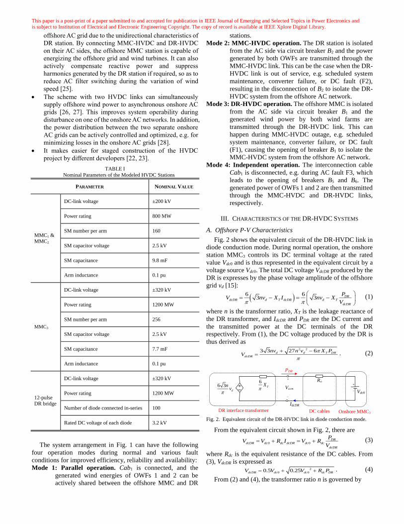
TABLE I
Nominal Parameters of the Modeled HVDC Stations
PARAMETER NOMINAL VALUE
MMC1 & MMC2
DC-link voltage ±200 kV
Power rating 800 MW
SM number per arm 160
SM capacitor voltage 2.5 kV
SM capacitance 9.8 mF
Arm inductance 0.1 pu
MMC3
DC-link voltage ±320 kV
Power rating 1200 MW
SM number per arm 256
SM capacitor voltage 2.5 kV
SM capacitance 7.7 mF
Arm inductance 0.1 pu
12-pulse DR bridge
DC-link voltage ±320 kV
Power rating 1200 MW
Number of diode connected in-series 100
Rated DC voltage of each diode 3.2 kV
The system arrangement in Fig. 1 can have the following
four operation modes during normal and various fault
conditions for improved efficiency, reliability and availability:
Mode 1: Parallel operation. Cab1 is connected, and the
generated wind energies of OWFs 1 and 2 can be
actively shared between the offshore MMC and DR
stations.
Mode 2: MMC-HVDC operation. The DR station is isolated
from the AC side via circuit breaker B2 and the power
generated by both OWFs are transmitted through the
MMC-HVDC link. This can be the case when the DR-
HVDC link is out of service, e.g. scheduled system
maintenance, converter failure, or DC fault (F2),
resulting in the disconnection of B2 to isolate the DR-
HVDC system from the offshore AC network.
Mode 3: DR-HVDC operation. The offshore MMC is isolated
from the AC side via circuit breaker B1 and the
generated wind power by both wind farms are
transmitted through the DR-HVDC link. This can
happen during MMC-HVDC outage, e.g. scheduled
system maintenance, converter failure, or DC fault
(F1), causing the opening of breaker B1 to isolate the
MMC-HVDC system from the offshore AC network.
Mode 4: Independent operation. The interconnection cable
Cab1 is disconnected, e.g. during AC fault F3, which
leads to the opening of breakers B5 and B6. The
generated power of OWFs 1 and 2 are then transmitted
through the MMC-HVDC and DR-HVDC links,
respectively.
III. CHARACTERISTICS OF THE DR-HVDC SYSTEMS
A. Offshore P-V Characteristics
Fig. 2 shows the equivalent circuit of the DR-HVDC link in
diode conduction mode. During normal operation, the onshore
station MMC3 controls its DC terminal voltage at the rated
value Vdc0 and is thus represented in the equivalent circuit by a
voltage source Vdc0. The total DC voltage VdcDR produced by the
DR is expresses by the phase voltage amplitude of the offshore
grid vd [15]:
6 6
3 3 DRdcDR d T dcDR d T
dcDR
PV nv X I nv X
V
(1)
where n is the transformer ratio, XT is the leakage reactance of
the DR transformer, and IdcDR and PDR are the DC current and
the transmitted power at the DC terminals of the DR
respectively. From (1), the DC voltage produced by the DR is
thus derived as
2 23 3 27 6d d T DR
dcDR
nv n v X PV
. (2)
Fig. 2. Equivalent circuit of the DR-HVDC link in diode conduction mode.
From the equivalent circuit shown in Fig. 2, there are
0 0
DRdcDR dc dc dcDR dc dc
dcDR
PV V R I V R
V (3)
where Rdc is the equivalent resistance of the DC cables. From
(3), VdcDR is expressed as
2
0 00.5 0.25dcDR dc dc dc DRV V V R P . (4)
From (2) and (4), the transformer ratio n is governed by
IdcDR
VdcDR
6 3d
nv
Rdc
Vdc0
6TX
DR interface transformer DC cables
+
–
Onshore MMC3
+
–
PDR
This paper is a post-print of a paper submitted to and accepted for publication in IEEE Journal of Emerging and Selected Topics in Power Electronics and
is subject to Institution of Electrical and Electronic Engineering Copyright. The copy of record is available at IEEE Xplore Digital Library.
2
0 0 00
20 0 0 0 0
2 4 2
24 3 3 4
dc dc dc DRT DR
d d dc dc dc DR
V V R P X Pn
V V V V R P
(5)
where PDR0 is the rated power of the DR-HVDC link and Vd0 is
the rated phase voltage amplitude of the offshore grid. Setting
the DR interface transformer ratio n according to (5), the DR
station transmits the rated power of PDR0 when the offshore
voltage is at the rated value Vd0.
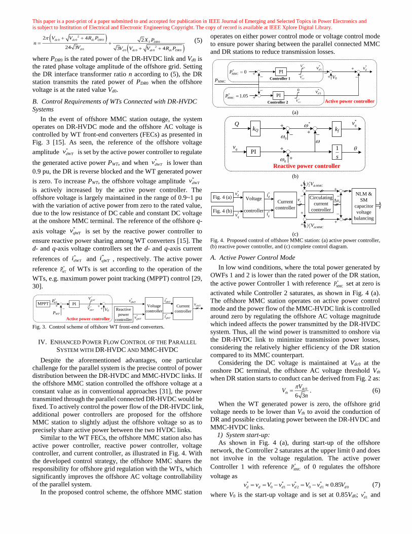
B. Control Requirements of WTs Connected with DR-HVDC
Systems
In the event of offshore MMC station outage, the system
operates on DR-HVDC mode and the offshore AC voltage is
controlled by WT front-end converters (FECs) as presented in
Fig. 3 [15]. As seen, the reference of the offshore voltage
amplitude *
dWTv is set by the active power controller to regulate
the generated active power PWT, and when *
dWTv is lower than
0.9 pu, the DR is reverse blocked and the WT generated power
is zero. To increase PWT, the offshore voltage amplitude *
dWTv
is actively increased by the active power controller. The
offshore voltage is largely maintained in the range of 0.9~1 pu
with the variation of active power from zero to the rated value,
due to the low resistance of DC cable and constant DC voltage
at the onshore MMC terminal. The reference of the offshore q-
axis voltage *
qWTv is set by the reactive power controller to
ensure reactive power sharing among WT converters [15]. The
d- and q-axis voltage controllers set the d- and q-axis current
references of *
dWTi and *
qWTi , respectively. The active power
reference *
WTP of WTs is set according to the operation of the
WTs, e.g. maximum power point tracking (MPPT) control [29,
30].
Fig. 3. Control scheme of offshore WT front-end converters.
IV. ENHANCED POWER FLOW CONTROL OF THE PARALLEL
SYSTEM WITH DR-HVDC AND MMC-HVDC
Despite the aforementioned advantages, one particular
challenge for the parallel system is the precise control of power
distribution between the DR-HVDC and MMC-HVDC links. If
the offshore MMC station controlled the offshore voltage at a
constant value as in conventional approaches [31], the power
transmitted through the parallel connected DR-HVDC would be
fixed. To actively control the power flow of the DR-HVDC link,
additional power controllers are proposed for the offshore
MMC station to slightly adjust the offshore voltage so as to
precisely share active power between the two HVDC links.
Similar to the WT FECs, the offshore MMC station also has
active power controller, reactive power controller, voltage
controller, and current controller, as illustrated in Fig. 4. With
the developed control strategy, the offshore MMC shares the
responsibility for offshore grid regulation with the WTs, which
significantly improves the offshore AC voltage controllability
of the parallel system.
In the proposed control scheme, the offshore MMC station
operates on either power control mode or voltage control mode
to ensure power sharing between the parallel connected MMC
and DR stations to reduce transmission losses.
(a)
(b)
(c)
Fig. 4. Proposed control of offshore MMC station: (a) active power controller, (b) reactive power controller, and (c) complete control diagram.
A. Active Power Control Mode
In low wind conditions, where the total power generated by
OWFs 1 and 2 is lower than the rated power of the DR station,
the active power Controller 1 with reference *
MMCP set at zero is
activated while Controller 2 saturates, as shown in Fig. 4 (a).
The offshore MMC station operates on active power control
mode and the power flow of the MMC-HVDC link is controlled
around zero by regulating the offshore AC voltage magnitude
which indeed affects the power transmitted by the DR-HVDC
system. Thus, all the wind power is transmitted to onshore via
the DR-HVDC link to minimize transmission power losses,
considering the relatively higher efficiency of the DR station
compared to its MMC counterpart.
Considering the DC voltage is maintained at Vdc0 at the
onshore DC terminal, the offshore AC voltage threshold Vth
when DR station starts to conduct can be derived from Fig. 2 as:
0
6 3
dcth
VV
n
. (6)
When the WT generated power is zero, the offshore grid
voltage needs to be lower than Vth to avoid the conduction of
DR and possible circulating power between the DR-HVDC and
MMC-HVDC links.
1) System start-up:
As shown in Fig. 4 (a), during start-up of the offshore
network, the Controller 2 saturates at the upper limit 0 and does
not involve in the voltage regulation. The active power
Controller 1 with reference *
MMCP of 0 regulates the offshore
voltage as
* * * *
0 1 2 0 1 00.85d d d dd dv v V v v Vv V (7)
where V0 is the start-up voltage and is set at 0.85Vd0; *
1dv and
+ _ ++ V0
PWT
Active power controller
*
WTPPI
Current
controller
Voltage
controllerReactive
power
controller
MPPTcWTv
*
qWTv
*
dWTv*
dWTi
*
qWTi
*
dlWTV
*
duWTV
+ _V0
PMMC
Active power controller
* 0MMCP
*
dv+
+PI
*
1dv
+
_* 1.05MMCP PI
*
2dv
Controller 1
Controller 2
__*
1d lV
0
*
1d uV
*
2d lV
+ _
*kfkQ
+_
Q
0
+
0 +
1
s
θ
Reactive power controller
qv
*
qv
PI
Current
controller
Voltage
controllerFig. 4 (b)*
qv
*
dv *
di
*
qi
Fig. 4 (a)
+
_
cv Δvc
+
+
12 dcMMCV
12 dcMMCV
+
_
+
_
Circulating
current
controller
NLM &
SM
capacitor
voltage
balancing

This paper is a post-print of a paper submitted to and accepted for publication in IEEE Journal of Emerging and Selected Topics in Power Electronics and
is subject to Institution of Electrical and Electronic Engineering Copyright. The copy of record is available at IEEE Xplore Digital Library.
*
2dv are the output of Controller 1 and 2, respectively. As V0 is
lower than the threshold voltage Vth defined by (6), DR is
reverse blocked. The total transmitted power transmission
between the offshore and onshore grids is thus zero.
2) DR conducting stage:
With the increase of the wind speed, the WTs start to
generate power and the offshore grid voltage is increased from
0.85Vd0 by the WT control strategy illustrated in Fig. 3. Once
the offshore network voltage is greater than the threshold
voltage Vth, the diode rectifiers conduct to transmit power and
the DC voltage of the diode station VdcDR is thus derived as:
0
0
33
6 .6
6
T dcd
dc dc d T dcdcDR
T dc T
dc
X Vnv
R nR v X VV
X R X
R
(8)
When the DR station transmits rated power PDR0, the
offshore voltage is regulated at the rated Vd0:
0 0d DR dv P V . (9)
From (6), (8), and (9) as well as the parameters as illustrated
in Fig. 1, it can be derived that the threshold voltage Vth is
around 0.9 pu, i.e. 0.9Vd0. With the variation of active power
from zero to the rated value, the offshore voltage can be
maintained within the safety operating region and is largely in
the range of 0.9~1 pu, due to the low resistance of DC cable and
constant DC voltage at the onshore MMC terminal.
At low wind power generation, Controller 1 with * 0MMCP
actively regulates the voltage reference *
dv to ensure all the
wind power is transmitted to onshore through the DR-HVDC
link and the active power PMMC flowing through MMC is zero.
The power-voltage profiles of the parallel connected MMC-
HVDC and DR-HVDC links are thus depicted as (10), which is
also illustrated in Fig. 5 (a) and (b), respectively.
0
2
0
0
,
MMC
th ddcDR dc dcDR
DR dcDR dcDR
d
d
c
P
V vV V VP V I
V
R
. (10)
(a) (b)
(c)
Fig. 5. Offshore power-voltage characteristics for the parallel operated MMC-HVDC and DR-HVDC links: (a) MMC-HVDC, (b) DR-HVDC, and (c) parallel
system.
B. Voltage Control Mode
When the generated wind power exceeds the capacity of the
DR-HVDC system, the transmitted power of DR station reaches
the rated value PDR0 and the surplus wind energy needs to be
transmitted through the MMC-HVDC link. As *
MMCP is set at
zero, the active power Controller 1 of the offshore MMC
saturates and outputs the lower limit *
1d lV which is set at -
0.15Vd0. Thus the MMC station operates on voltage control
mode and regulates the offshore voltage at rated value:
* * * *
0 1 2 0 1 0d d d d dd lv v V v v V V V . (11)
As seen, both the active power controllers saturate and the
offshore MMC autonomously and seamlessly transfers from
power control mode to voltage control mode without the need
for communication or operation mode detection. The DR
station operates with rated power PDR0 while the extra generated
power is transmitted to onshore via the MMC-HVDC link:
0
1 2 0
0
,MMC F F DR
d
DR
d
DR
P P P Pv
PV
P
(12)
where PF1 and PF2 are the active power generated by OWFs 1
and 2, respectively. From (10) and (12), the relationship
between the offshore voltage and the total transmitted power Pto
can be expressed by (13) and is also illustrated in Fig. 5 (c).
0
22
0 0 0
3
0
/2
1 2
0,
3 6 36 , .
66
,
to MMC DR
d th
dc d T dc dc dc d T dcth d
dc dc Tdc T d
d
d
c
F F d
P P P
v V
nR v X V nR V v X VV v
R R XR X R
P P
V
Vv
(13)
C. Active Power Limiting Control in Mode 2
In MMC-HVDC operation (Mode 2), the DR station is
isolated from the offshore network and the power from both
OWFs 1 and 2 is transmitted to the onshore through the MMC-
HVDC link, which can be higher than MMC’s transmission
capability. The active power Controller 2 as shown in Fig. 4 (a)
is thus proposed to automatically reduce the generated wind
power and avoid overloading of the MMC-HVD link.
As shown in Fig. 4 (a), with the power reference *
MMCP set at
1.05 pu, the output of Controller 2 of the offshore MMC1
saturates at the upper limit of zero during normal operation and
does not involve in the offshore voltage regulation. Once the
MMC power is over 1.05 pu, Controller 2 activates and slightly
increases the offshore AC voltage. Consequently, the active
power controllers of the WTs saturate and the WTs operate on
voltage control mode. Without communication, the power
generated by WTs is automatically reduced and the potential
overloading of the MMC-HVDC system is avoided, as shown
in Fig. 5 (b). To alleviate the WT DC overvoltage and avoid
over-speed of WT generators, pitch control is adopted to reduce
the captured wind energy [32, 33]. DC chopper can also be used
to dissipate the generated surplus wind power [34, 35].
The offshore MMC regulates the offshore network voltage
to enable enhanced power sharing between the DR-HVDC and
MMC-HVDC links. The coordinated control between the
offshore MMC and WTs relies on the local measurements
without any communication requirement. The proposed control
scheme can seamlessly handle transitions between active power
control and voltage control modes as well as various faults for
the parallel system, as will be demonstrated in Section V.
VthdvVd00.85Vd0
PMMC
0
1.05PMMC0
Vth dvVd00.85Vd0
PDR
PDR0
0
Vth dvVd00.85Vd0
Pto
PDR
0
PDR0+1.05PMMC0
Power control mode
Voltage control mode
Power limiting mode

This paper is a post-print of a paper submitted to and accepted for publication in IEEE Journal of Emerging and Selected Topics in Power Electronics and
is subject to Institution of Electrical and Electronic Engineering Copyright. The copy of record is available at IEEE Xplore Digital Library.
D. Power Curtailment Control by Onshore Station MMC3 in
Mode 3
In DR-HVDC operation (Mode 3), the offshore MMC
station is isolated from the offshore grid and the wind powers
generated by both OWFs 1 and 2 are transmitted via the DR-
HVDC link. The maximum power transmission capability of
the system is thus reduced to 0.6 pu for the considered
configuration. To avoid overloading of the DR-HVDC link, a
power curtailment control for the onshore MMC3 is presented
in Fig. 6, where an additional DC current loop is adopted to
increase the DC voltage Vdc once DC overcurrents occur. As
shown, if the DC current Idc is lower than the pre-set maximum
DC current order *dcI (e.g. 1.1 pu), the input of the PI controller
is limited at zero by the dead zone block such that the DC
voltage order *dcV for the onshore MMC3 of the DR-HVDC is
at the rated value. If Idc exceeds the maximum value, the PI
controller generates a positive output to slightly increase the DC
voltage of the DR-HVDC so the power transmitted from the DR
and WTs is automatically limited. In the meantime, the WTs
will limit the generated power through pitch control [32, 33].
Fig. 6. Power curtailment control of onshore station MMC3 in DR-HVDC link.
E. Reactive Power Sharing Control
1) Control design
In addition to AC side filters, the offshore MMC and WT
converters can compensate the reactive power consumed by the
DR station. To share the required reactive power among the
offshore MMC station and WTs, reactive power frequency (Q-
f) droop control as shown in Fig. 4 (b) is adopted to dynamically
set the frequency reference * as [10, 12, 36, 37]:
*
0 Qk Q (14)
where 0 is the rated frequency of the offshore network, kQ is
the droop gain, and Q is the reactive power. The per-unit value
of the reactive power of each WT and offshore MMC1 is
measured and fed to the frequency loop for reactive power
sharing (proportional to their own capacity). The offshore
network frequency is derived by PLL and fed to the frequency
loop, which sets the q-axis voltage reference *
qv to regulate the
offshore AC frequency [15].
2) Operating principle for reactive power sharing
To illustrate the operating principle of the reactive power
sharing control, a single-phase representation of the system is
shown in Fig. 7 (a), where VMMC is the amplitude of the voltage
at the MMC AC terminal whose phase angle is taken as the
reference (zero), Vi and θi (i=1, 2, …, h) are the respective
output voltage amplitude and phase angle of the FEC of the ith
WT, and Xi is the equivalent reactance between the ith WT and
the MMC AC terminal.
Assuming the reactive power Q1 of WT 1 is greater than the
average reactive power of other WTs and the offshore MMC
station (in per unit terms) and is required to be reduced, the
frequency reference 1* of WT 1 is higher than that of other
WTs due to the reactive power frequency (Q-f) droop control
depicted by (14). Consequently, the phase difference θ1
between V1 and VMMC (phase angle of VMMC is used as the
reference) increases. The voltage amplitude VMMC at the MMC
AC terminal is determined by the transmitted active power
PdcDR as depicted by (15) and remains unchanged:
20 00
3 3 1 3
18 3 2 4 3
T dc T dcMMC dc DC dcDR
dc dc
X V X VV V R P
n nR nR
. (15)
(a)
(b)
Fig. 7. Reactive power sharing illustration: (a) single-phase diagram of the offshore network and (b) relationship among control variables.
The active power output P1 of WT 1 tends to increase due to
the increased angle θ1 as governed by (16). In the meantime, the
increase of P1 causes the active power controller to reduce the
output voltage V1 to ensure P1 unchanged. The reactive power
Q1, as expressed as (17), is thus reduced, yielding shared
reactive power among the offshore WTs and MMC station. The
relationships of the different variables are graphically shown in
Fig. 7 (b) for ease of understanding.
0 1 11
1
sinV VP
X
(16)
1 1 0 1
1
1
cosV V VQ
X
(17)
V. SIMULATION
The proposed control scheme is assessed using the model
shown in Fig. 1 in PSCAD X4, where OWFs 1 and 2 are
represented by 4 and 6 lumped converters each rated at 200 MW
respectively. Thus, a total of 10 WT converters are considered
in this paper and small-signal modelling method is used for
tuning WT control parameters, where the eigenvalues of the
linearized small-signal model are calculated and suitable
parameters of the converter controllers are obtained to ensure
dynamic stability [5, 38-40]. The generator-side converter is
simplified as a DC voltage source of 1100 V [12, 14, 41] while
the aggregated FECs and the DR station are represented by
detailed switching models. The MMC stations are represented
by detailed submodule-based switching function model [42].
The combined system time delay introduced by sampling,
calculation, and modulation is 63 µs, 63 µs, 36 µs, and 750 µs
for MMC1, MMC2, MMC3, and WT converters, respectively
[43, 44].
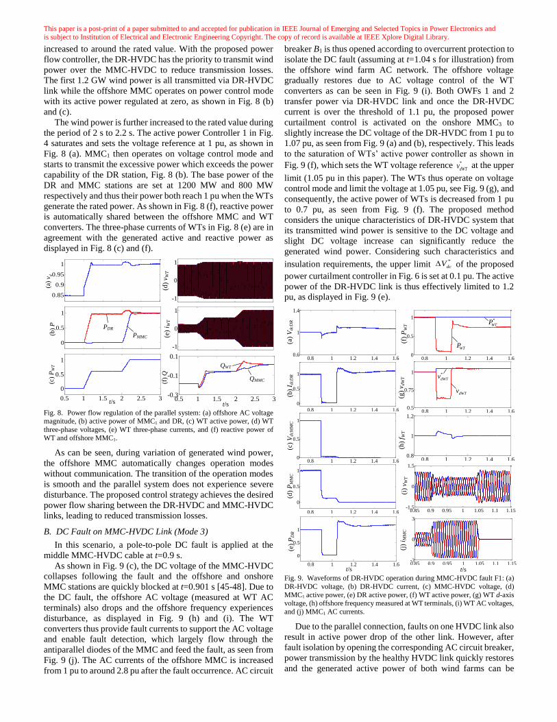
A. Power Flow Regulation in Parallel Operation (Mode 1)
Fig. 8 presents simulation results with the proposed power
flow control. Initially, the output power of the WTs is zero as
shown in Fig. 8 (c), and the offshore voltage is controlled
around 0.85 pu, as seen in Fig. 8 (a). At t=1 s, the wind power
ramps up to 0.6 pu within 0.2 s by increasing the voltage as
observed in Fig. 8 (d), and the offshore AC voltage is gradually
+
_ +
++ _
Vdc0
Idc
*
dcIPI
Vdc
*
dcVPI
Dead zoneCurrent
controller
cv
*
di
*
qiPower curtailment control
0
*
dcV
X1
P1, Q1 VMMC
1 1V
X2
P2, Q2
2 2V
Xh
Ph, Qh
h hV
Q1 1 1 1P 1V(14) (16)
(17)
This paper is a post-print of a paper submitted to and accepted for publication in IEEE Journal of Emerging and Selected Topics in Power Electronics and
is subject to Institution of Electrical and Electronic Engineering Copyright. The copy of record is available at IEEE Xplore Digital Library.
increased to around the rated value. With the proposed power
flow controller, the DR-HVDC has the priority to transmit wind
power over the MMC-HVDC to reduce transmission losses.
The first 1.2 GW wind power is all transmitted via DR-HVDC
link while the offshore MMC operates on power control mode
with its active power regulated at zero, as shown in Fig. 8 (b)
and (c).
The wind power is further increased to the rated value during
the period of 2 s to 2.2 s. The active power Controller 1 in Fig.
4 saturates and sets the voltage reference at 1 pu, as shown in
Fig. 8 (a). MMC1 then operates on voltage control mode and
starts to transmit the excessive power which exceeds the power
capability of the DR station, Fig. 8 (b). The base power of the
DR and MMC stations are set at 1200 MW and 800 MW
respectively and thus their power both reach 1 pu when the WTs
generate the rated power. As shown in Fig. 8 (f), reactive power
is automatically shared between the offshore MMC and WT
converters. The three-phase currents of WTs in Fig. 8 (e) are in
agreement with the generated active and reactive power as
displayed in Fig. 8 (c) and (f).
Fig. 8. Power flow regulation of the parallel system: (a) offshore AC voltage magnitude, (b) active power of MMC1 and DR, (c) WT active power, (d) WT
three-phase voltages, (e) WT three-phase currents, and (f) reactive power of
WT and offshore MMC1.
As can be seen, during variation of generated wind power,
the offshore MMC automatically changes operation modes
without communication. The transition of the operation modes
is smooth and the parallel system does not experience severe
disturbance. The proposed control strategy achieves the desired
power flow sharing between the DR-HVDC and MMC-HVDC
links, leading to reduced transmission losses.
B. DC Fault on MMC-HVDC Link (Mode 3)
In this scenario, a pole-to-pole DC fault is applied at the
middle MMC-HVDC cable at t=0.9 s.
As shown in Fig. 9 (c), the DC voltage of the MMC-HVDC
collapses following the fault and the offshore and onshore
MMC stations are quickly blocked at t=0.901 s [45-48]. Due to
the DC fault, the offshore AC voltage (measured at WT AC
terminals) also drops and the offshore frequency experiences
disturbance, as displayed in Fig. 9 (h) and (i). The WT
converters thus provide fault currents to support the AC voltage
and enable fault detection, which largely flow through the
antiparallel diodes of the MMC and feed the fault, as seen from
Fig. 9 (j). The AC currents of the offshore MMC is increased
from 1 pu to around 2.8 pu after the fault occurrence. AC circuit
breaker B1 is thus opened according to overcurrent protection to
isolate the DC fault (assuming at t=1.04 s for illustration) from
the offshore wind farm AC network. The offshore voltage
gradually restores due to AC voltage control of the WT
converters as can be seen in Fig. 9 (i). Both OWFs 1 and 2
transfer power via DR-HVDC link and once the DR-HVDC
current is over the threshold of 1.1 pu, the proposed power
curtailment control is activated on the onshore MMC3 to
slightly increase the DC voltage of the DR-HVDC from 1 pu to
1.07 pu, as seen from Fig. 9 (a) and (b), respectively. This leads
to the saturation of WTs’ active power controller as shown in
Fig. 9 (f), which sets the WT voltage reference *
dWTv at the upper
limit (1.05 pu in this paper). The WTs thus operate on voltage
control mode and limit the voltage at 1.05 pu, see Fig. 9 (g), and
consequently, the active power of WTs is decreased from 1 pu
to 0.7 pu, as seen from Fig. 9 (f). The proposed method
considers the unique characteristics of DR-HVDC system that
its transmitted wind power is sensitive to the DC voltage and
slight DC voltage increase can significantly reduce the
generated wind power. Considering such characteristics and
insulation requirements, the upper limit *
dcV of the proposed
power curtailment controller in Fig. 6 is set at 0.1 pu. The active
power of the DR-HVDC link is thus effectively limited to 1.2
pu, as displayed in Fig. 9 (e).
Fig. 9. Waveforms of DR-HVDC operation during MMC-HVDC fault F1: (a)
DR-HVDC voltage, (b) DR-HVDC current, (c) MMC-HVDC voltage, (d)
MMC1 active power, (e) DR active power, (f) WT active power, (g) WT d-axis voltage, (h) offshore frequency measured at WT terminals, (i) WT AC voltages,
and (j) MMC1 AC currents.
Due to the parallel connection, faults on one HVDC link also
result in active power drop of the other link. However, after
fault isolation by opening the corresponding AC circuit breaker,
power transmission by the healthy HVDC link quickly restores
and the generated active power of both wind farms can be
0.5 1 1.5 2 2.5 3-0.3
-0.1
0.1
-1
0
1
0.85
0.9
0.95
1
(a)
dv
QWT
QMMC
t/s
0
0.5
1
(b)
P PDR
PMMC
0.5 1 1.5 2 2.5 3
0
0.5
1
(c)
PW
T
t/s
-1
0
1
(d)
v WT
(e)
i WT
(f)
Q
0.8 1 1.2 1.4 1.60.8
1
1.20.8 1 1.2 1.4 1.6
0.5
0.75
1
0.85 0.9 0.95 1 1.05 1.1 1.15-3
0
3
0.8 1 1.2 1.4 1.60
0.5
1
0.8 1 1.2 1.4 1.6
0
0.5
1
(c)
Vd
cMM
C(b
) I d
cDR
0.8 1 1.2 1.4 1.60
0.5
1
0.85 0.9 0.95 1 1.05 1.1 1.15-1.5
0
1.5
0.8 1 1.2 1.4 1.60.6
1
1.4
(a)
Vd
cDR
(j)
i MM
C(i
) v W
T(f
) P
WT
t/s
WTP
*
WTP
0.8 1 1.2 1.4 1.6
0
0.5
1
(d)
PM
MC
0.8 1 1.2 1.4 1.6
0
0.5
1
(e)
PD
R
t/s
(h)
f WT
(g)
v dW
T *
dWTv
dWTv
This paper is a post-print of a paper submitted to and accepted for publication in IEEE Journal of Emerging and Selected Topics in Power Electronics and
is subject to Institution of Electrical and Electronic Engineering Copyright. The copy of record is available at IEEE Xplore Digital Library.
transmitted to onshore networks.
Without communication, the generated wind power is
automatically reduced after MMC-HVDC faults and the
potential DC overcurrents of the DR-HVDC link are thus
avoided. To avoid over-speed of the WT generators, the WTs
need to limit the power through pitch control [32, 33].
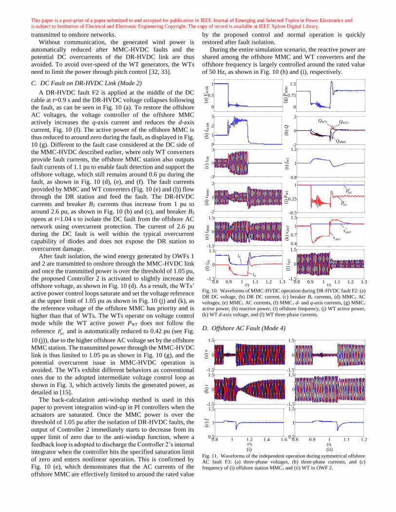
C. DC Fault on DR-HVDC Link (Mode 2)
A DR-HVDC fault F2 is applied at the middle of the DC
cable at t=0.9 s and the DR-HVDC voltage collapses following
the fault, as can be seen in Fig. 10 (a). To restore the offshore
AC voltages, the voltage controller of the offshore MMC
actively increases the q-axis current and reduces the d-axis
current, Fig. 10 (f). The active power of the offshore MMC is
thus reduced to around zero during the fault, as displayed in Fig.
10 (g). Different to the fault case considered at the DC side of
the MMC-HVDC described earlier, where only WT converters
provide fault currents, the offshore MMC station also outputs
fault currents of 1.1 pu to enable fault detection and support the
offshore voltage, which still remains around 0.6 pu during the
fault, as shown in Fig. 10 (d), (e), and (f). The fault currents
provided by MMC and WT converters (Fig. 10 (e) and (l)) flow
through the DR station and feed the fault. The DR-HVDC
currents and breaker B2 currents thus increase from 1 pu to
around 2.6 pu, as shown in Fig. 10 (b) and (c), and breaker B2
opens at t=1.04 s to isolate the DC fault from the offshore AC
network using overcurrent protection. The current of 2.6 pu
during the DC fault is well within the typical overcurrent
capability of diodes and does not expose the DR station to
overcurrent damage.
After fault isolation, the wind energy generated by OWFs 1
and 2 are transmitted to onshore through the MMC-HVDC link
and once the transmitted power is over the threshold of 1.05 pu,
the proposed Controller 2 is activated to slightly increase the
offshore voltage, as shown in Fig. 10 (d). As a result, the WTs’
active power control loops saturate and set the voltage reference
at the upper limit of 1.05 pu as shown in Fig. 10 (j) and (k), as
the reference voltage of the offshore MMC has priority and is
higher than that of WTs. The WTs operate on voltage control
mode while the WT active power PWT does not follow the
reference *
WTP and is automatically reduced to 0.42 pu (see Fig.
10 (j)), due to the higher offshore AC voltage set by the offshore
MMC station. The transmitted power through the MMC-HVDC
link is thus limited to 1.05 pu as shown in Fig. 10 (g), and the
potential overcurrent issue in MMC-HVDC operation is
avoided. The WTs exhibit different behaviors as conventional
ones due to the adopted intermediate voltage control loop as
shown in Fig. 3, which actively limits the generated power, as
detailed in [15].
The back-calculation anti-windup method is used in this
paper to prevent integration wind-up in PI controllers when the
actuators are saturated. Once the MMC power is over the
threshold of 1.05 pu after the isolation of DR-HVDC faults, the
output of Controller 2 immediately starts to decrease from its
upper limit of zero due to the anti-windup function, where a
feedback loop is adopted to discharge the Controller 2’s internal
integrator when the controller hits the specified saturation limit
of zero and enters nonlinear operation. This is confirmed by
Fig. 10 (e), which demonstrates that the AC currents of the
offshore MMC are effectively limited to around the rated value
by the proposed control and normal operation is quickly
restored after fault isolation.
During the entire simulation scenario, the reactive power are
shared among the offshore MMC and WT converters and the
offshore frequency is largely controlled around the rated value
of 50 Hz, as shown in Fig. 10 (h) and (i), respectively.
Fig. 10. Waveforms of MMC-HVDC operation during DR-HVDC fault F2: (a)
DR DC voltage, (b) DR DC current, (c) breaker B2 currents, (d) MMC1 AC voltages, (e) MMC1 AC currents, (f) MMC1 d- and q-axis currents, (g) MMC1
active power, (h) reactive power, (i) offshore frequency, (j) WT active power,
(k) WT d-axis voltage, and (l) WT three-phase currents.
D. Offshore AC Fault (Mode 4)
Fig. 11. Waveforms of the independent operation during symmetrical offshore AC fault F3: (a) three-phase voltages, (b) three-phase currents, and (c)
frequency of (i) offshore station MMC1 and (ii) WT in OWF 2.
0.4
0.7
1
1.3
-3
0
3
0
0.5
1
0
1
2
3
-2
0
2
0
0.75
1.5
(c)
i DR
(h)
Q(g
) P
MM
C(i
) f W
T
(a)
VdcD
R(b
) I d
cDR
(j)
PW
T(k
) v d
WT
t/s
QMMC
QWT2QWT1
0.8
1
1.2
0.8 0.9 1 1.1 1.2 1.3-1.5
0
1.5
-2
0
2
-1.5
0
1.5
0.8 0.9 1 1.1 1.2 1.3-1.5
0
1.5
(e)
i MM
C(d
) v M
MC
(f)
i dq
t/s
id
iq
(l)
i WT
-0.5
0.25
1
*
dWTv
dWTv
WTP
*
WTP
t/s
0.8 1 1.2 1.4 1.60.5
1
1.5
-1.5
0
1.5
-1.5
0
1.5
0.8 0.9 1 1.1 1.20.5
1
1.5-1.5
0
1.5
-1.5
0
1.5
(b)
i(a
) v
(c)
f
(ii)(i)t/s t/s

This paper is a post-print of a paper submitted to and accepted for publication in IEEE Journal of Emerging and Selected Topics in Power Electronics and
is subject to Institution of Electrical and Electronic Engineering Copyright. The copy of record is available at IEEE Xplore Digital Library.
As shown in Fig. 11 (a), the offshore AC voltage drops to
around 0.1 pu after the solid fault F3 at the interconnection
cable Cab1 at t=0.9 s. Both the active power and voltage control
loops saturate and thus set the d-axis current reference at its
limit. Therefore, both the offshore MMC and WTs operate on
current limiting mode to provide fault currents so as to support
the offshore network and enable fault detection, as displayed in
Fig. 11 (b). At t=1.04 s, breakers B5 and B6 open to isolate the
fault and then the MMC-HVDC and DR-HVDC systems
operate independently. With the developed control strategy, the
offshore voltages of the two isolated offshore networks both
restore quickly following the fault isolation and can be properly
controlled by the MMC and WTs respectively, as seen from
Fig. 11 (i) and (ii). The generated power of OWFs 1 and 2 is
thus transmitted to onshore via the MMC-HVDC and DR-
HVDC links, respectively. The offshore frequency experiences
disturbance during the fault and gradually recovers after fault
isolation, as shown in Fig. 11 (c).
E. Efficiency Evaluation
To further demonstrate the efficiency superiority of the
proposed scheme, the loss evaluations of the tested model with
parameters listed in Table I are carried out using the methods as
detailed in [49-51]. The semiconductor losses are obtained
according to the currents in the simulation and the
characteristics of the semiconductor devices [52]. The latter are
derived from the datasheet provided by the manufacturer [53,
54] and are stored in a lookup table.
On DR operation, all the generated wind power is
transmitted through the DR-HVDC link with the proposed
control. When transmitting rated power of 1200 MW, the loss
of the offshore DR station is 5.8 MW, leading to an efficiency
of 99.5%, which is higher than the typical efficiency of MMCs
(approximately 99%) [55]. The power losses of the offshore DR
(1200 MW) and MMC (800 MW) on parallel operation are 5.8
MW and 7.3 MW, respectively, leading to an overall efficiency
of 99.3%. The proposed coordinated control significantly
reduces power losses, where the DR-HVDC has the priority to
transmit wind power considering the higher efficiency of DR-
HVDC compared to its MMC counterpart.
VI. CONCLUSION
DR-HVDC and MMC-HVDC are proposed to transmit
offshore wind power where the two DC links operate in parallel
with the offshore MMC and DR stations both connected to the
offshore wind farm AC network. An enhanced active power
control scheme of the offshore MMC station is proposed to
improve the power flow distribution between offshore MMC
and DR stations during parallel operation. By regulating the
offshore voltage, all the wind powers are transmitted via DR-
HVDC link in low wind conditions while the offshore MMC
power is controlled around zero to reduce transmission losses.
In high power condition, the offshore MMC controls the
offshore AC voltage at the rated value and shares wind energy
transmission with the DR-HVDC link. To deal with the
operation of single HVDC link when the other DC link is out of
service due to scheduled shutdown, faults etc., coordinated
control strategies have been proposed to automatically curtail
the generated wind power to avoid potential overload of either
the DR-HVDC or MMC-HVDC link. The proposed
coordinated control does not rely on communication and can
seamlessly handle transitions due to the change of operation
conditions and faults. The proposed scheme provides a high
efficient solution with flexible operation for integrating large
offshore wind farms.
VII. REFERENCES
[1] M. Amin, A. Rygg, and M. Molinas, "Self-Synchronization of Wind Farm
in an MMC-Based HVDC System: A Stability Investigation," IEEE
Transactions on Energy Conversion, vol. 32, pp. 458-470, 2017. [2] J. Lyu, X. Cai, and M. Molinas, "Frequency Domain Stability Analysis of
MMC-Based HVdc for Wind Farm Integration," IEEE Journal of
Emerging and Selected Topics in Power Electronics, vol. 4, pp. 141-151, 2016.
[3] K. Schönleber, E. Prieto-Araujo, S. Ratés-Palau, and O. Gomis-Bellmunt,
"Extended Current Limitation for Unbalanced Faults in
MMC–HVDC–connected Wind Power Plants," IEEE
Transactions on Power Delivery, vol. PP, pp. 1-1, 2017.
[4] L. Zhang, L. Harnefors, and H. P. Nee, "Interconnection of Two Very Weak AC Systems by VSC-HVDC Links Using Power-Synchronization
Control," IEEE Transactions on Power Systems, vol. 26, pp. 344-355,
2011. [5] L. Zhang, L. Harnefors, and H. P. Nee, "Modeling and Control of VSC-
HVDC Links Connected to Island Systems," IEEE Transactions on Power
Systems, vol. 26, pp. 783-793, 2011. [6] J. Svensson, "Synchronisation methods for grid-connected voltage source
converters," IEE Proceedings - Generation, Transmission and Distribution, vol. 148, pp. 229-235, 2001.
[7] W. Wang, Y. Li, Y. Cao, U. Häger, and C. Rehtanz, "Adaptive Droop
Control of VSC-MTDC System for Frequency Support and Power Sharing," IEEE Transactions on Power Systems, vol. 33, pp. 1264-1274,
2018.
[8] J. N. Sakamuri, M. Altin, A. D. Hansen, and N. A. Cutululis, "Coordinated
frequency control from offshore wind power plants connected to multi
terminal DC system considering wind speed variation," IET Renewable
Power Generation, vol. 11, pp. 1226-1236, 2017. [9] O. Kuhn, P. Menke, R. Zurowski, T. Christ, S. Seman, G. Giering, et al.,
"2nd generation DC grid access for offshore wind farms: HVDC in an AC
fashion," CIGRE, Paris, pp. 1-7, 2016. [10] S. Seman, R. Zurowski, and C. Taratoris, "Interconnection of advanced
Type 4 WTGs with Diode Rectifier based HVDC solution and weak AC
grids," in Proceedings of the 14th Wind Integration Workshop,Brussels, Belgium, 20th–22nd Oct. , 2015.
[11] T. H. Nguyen, D. C. Lee, and C. K. Kim, "A Series-Connected Topology
of a Diode Rectifier and a Voltage-Source Converter for an HVDC Transmission System," IEEE Trans. Power Electron., vol. 29, pp. 1579-
1584, 2014.
[12] R. Blasco-Gimenez, S. A.-. Villalba, J. Rodríguez-D'Derlée, F. Morant, and S. Bernal-Perez, "Distributed Voltage and Frequency Control of Offshore
Wind Farms Connected With a Diode-Based HVdc Link," IEEE
Transactions on Power Electronics, vol. 25, pp. 3095-3105, 2010. [13] S. Bernal-Perez, S. Ano-Villalba, R. Blasco-Gimenez, and J. Rodriguez-
D'Derlee, "Efficiency and Fault Ride-Through Performance of a Diode-
Rectifier- and VSC-Inverter-Based HVDC Link for Offshore Wind Farms," IEEE Transactions on Industrial Electronics, vol. 60, pp. 2401-
2409, 2013.
[14] R. Blasco-Gimenez, S. Anó-Villalba, J. Rodriguez-D'Derlée, S. Bernal-Perez, and F. Morant, "Diode-Based HVdc Link for the Connection of
Large Offshore Wind Farms," IEEE Transactions on Energy Conversion,
vol. 26, pp. 615-626, 2011. [15] L. Yu, R. Li, and L. Xu, "Distributed PLL-Based Control of Offshore Wind
Turbines Connected With Diode-Rectifier-Based HVDC Systems," IEEE
Transactions on Power Delivery, vol. 33, pp. 1328-1336, 2018. [16] R. Li, L. Yu, and L. Xu, "Offshore AC Fault Protection of Diode Rectifier
Unit Based HVDC System for Wind Energy Transmission," IEEE
Transactions on Industrial Electronics, pp. 1-1, 2018.
[17] R. Zeng, L. Xu, L. Yao, and B. W. Williams, "Design and Operation of a
Hybrid Modular Multilevel Converter," Power Electronics, IEEE
Transactions on, vol. 30, pp. 1137-1146, 2015. [18] G. Zou, Q. Huang, S. Song, B. Tong, and H. Gao, "Novel transient-energy-
based directional pilot protection method for HVDC line," Protection and
Control of Modern Power Systems, vol. 2, p. 15, April 20 2017.

This paper is a post-print of a paper submitted to and accepted for publication in IEEE Journal of Emerging and Selected Topics in Power Electronics and
is subject to Institution of Electrical and Electronic Engineering Copyright. The copy of record is available at IEEE Xplore Digital Library.
[19] L. Yu, R. Li, and L. Xu, "Hierarchical control of offshore wind farm
connected by parallel diode-rectifier-based HVDC and HVAC links," IET Renewable Power Generation, vol. 13, pp. 1493-1502, 2019.
[20] T. Kawaguchi, T. Sakazaki, T. Isobe, and R. Shimada, "Offshore-Wind-
Farm Configuration Using Diode Rectifier With MERS in Current Link Topology," IEEE Transactions on Industrial Electronics, vol. 60, pp. 2930-
2937, 2013.
[21] ABB, "HVDC technology for offshore wind is maturing," https://new.abb.com/news/detail/8270/hvdc-technology-for-offshore-
wind-is-maturing, 2018.
[22] J. L. Rodríguez-Amenedo, S. Arnaltes-Gómez, M. Aragüés-Peñalba, and O. Gomis-Bellmunt, "Control of the Parallel Operation of VSC-HVDC
Links Connected to an Offshore Wind Farm," IEEE Transactions on Power
Delivery, vol. 34, pp. 32-41, 2019. [23] "CIGRE Working group B4-55, Technical Brochure 619, HVDC
connection of offshore wind power plants," Int. Council Large Electric
Syst, (CIGRE), pp. 8–11, 2015. [24] R. Li, L. Xu, D. Holliday, F. Page, S. J. Finney, and B. W. Williams,
"Continuous Operation of Radial Multiterminal HVDC Systems Under DC
Fault," IEEE Transactions on Power Delivery, vol. 31, pp. 351-361, 2016. [25] Y. Chang and X. Cai, "Hybrid Topology of a Diode-Rectifier-based HVDC
System for Offshore Wind Farms," IEEE Journal of Emerging and Selected
Topics in Power Electronics, pp. 1-1, 2018. [26] energinet, "KRIEGERS FLAK - COMBINED GRID SOLUTION,"
https://en.energinet.dk/Infrastructure-
Projects/Projektliste/KriegersFlakCGS, 2018. [27] A. Marten, V. Akmatov, T. B. Sørensen, R. Stornowski, D. Westermann,
and C. Brosinsky, "Kriegers flak-combined grid solution: coordinated cross-border control of a meshed HVAC/HVDC offshore wind power
grid," IET Renewable Power Generation, vol. 12, pp. 1493-1499, 2018.
[28] V. Lescale, P. Holmberg, R. Ottersten, and Y. Hafner, "Parallelling offshore wind farms HVDC ties on offshore side," Proceedings of CIGRE
2012, 2012.
[29] Y. Fu, Y. Wang, and X. Zhang, "Integrated wind turbine controller with virtual inertia and primary frequency responses for grid dynamic frequency
support," IET Renewable Power Generation, vol. 11, pp. 1129-1137, 2017.
[30] Y. Wang, M. Yu, and Y. Li, "Self-adaptive inertia control of DC microgrid based on fast predictive converter regulation," IET Renewable Power
Generation, vol. 11, pp. 1295-1303, 2017.
[31] X. Hu, J. Liang, D. J. Rogers, and Y. Li, "Power Flow and Power Reduction Control Using Variable Frequency of Offshore AC Grids," IEEE
Transactions on Power Systems, vol. 28, pp. 3897-3905, 2013.
[32] M. J. Hossain, H. R. Pota, V. A. Ugrinovskii, and R. A. Ramos, "Simultaneous STATCOM and Pitch Angle Control for Improved LVRT
Capability of Fixed-Speed Wind Turbines," IEEE Transactions on
Sustainable Energy, vol. 1, pp. 142-151, 2010. [33] M. Firouzi, G. B. Gharehpetian, and S. B. Mozafari, "Application of UIPC
to improve power system stability and LVRT capability of SCIG-based
wind farms," IET Generation, Transmission & Distribution, vol. 11, pp. 2314-2322, 2017.
[34] H. Geng, L. Liu, and R. Li, "Synchronization and Reactive Current Support
of PMSG based Wind Farm during Severe Grid Fault," IEEE Transactions
on Sustainable Energy, vol. PP, pp. 1-1, 2018.
[35] M. Nasiri and R. Mohammadi, "Peak Current Limitation for Grid Side
Inverter by Limited Active Power in PMSG-Based Wind Turbines During Different Grid Faults," IEEE Transactions on Sustainable Energy, vol. 8,
pp. 3-12, 2017.
[36] R. Blasco-Gimenez, N. Aparicio, S. Ano-Villalba, and S. Bernal-Perez, "LCC-HVDC Connection of Offshore Wind Farms With Reduced Filter
Banks," IEEE Transactions on Industrial Electronics, vol. 60, pp. 2372-
2380, 2013. [37] J. Renedo, A. García-Cerrada, and L. Rouco, "Reactive-Power
Coordination in VSC-HVDC Multi-Terminal Systems for Transient
Stability Improvement," IEEE Transactions on Power Systems, vol. 32, pp.
3758-3767, 2017.
[38] G. O. Kalcon, G. P. Adam, O. Anaya-Lara, S. Lo, and K. Uhlen, "Small-
Signal Stability Analysis of Multi-Terminal VSC-Based DC Transmission
Systems," IEEE Transactions on Power Systems, vol. 27, pp. 1818-1830, 2012.
[39] Y. Li, G. Tang, T. An, H. Pang, P. Wang, J. Yang, et al., "Power
Compensation Control for Interconnection of Weak Power Systems by VSC-HVDC," IEEE Transactions on Power Delivery, vol. 32, pp. 1964-
1974, 2017.
[40] S. Mortazavian, M. M. Shabestary, and Y. A. R. I. Mohamed, "Analysis and Dynamic Performance Improvement of Grid-Connected
Voltage–Source Converters Under Unbalanced Network
Conditions," IEEE Transactions on Power Electronics, vol. 32, pp. 8134-8149, 2017.
[41] O. D. Adeuyi, M. Cheah-Mane, J. Liang, and N. Jenkins, "Fast Frequency
Response From Offshore Multiterminal VSC–HVDC Schemes," IEEE Transactions on Power Delivery, vol. 32, pp. 2442-2452, 2017.
[42] R. Li, L. Xu, and D. Guo, "Accelerated switching function model of hybrid
MMCs for HVDC system simulation," IET Power Electronics, vol. 10, pp. 2199-2207, 2017.
[43] C. Dong, S. Yang, H. Jia, and P. Wang, "Padé-Based Stability Analysis for
a Modular Multilevel Converter Considering the Time Delay in the Digital Control System," IEEE Transactions on Industrial Electronics, vol. 66, pp.
5242-5253, 2019.
[44] C. Wang, L. Xiao, H. Jiang, and T. Cai, "Analysis and Compensation of the System Time Delay in an MMC System," IEEE Transactions on Power
Electronics, vol. 33, pp. 9923-9936, 2018. [45] Y. Jin, J. E. Fletcher, and J. O'Reilly, "Multiterminal DC Wind Farm
Collection Grid Internal Fault Analysis and Protection Design," Power
Delivery, IEEE Transactions on, vol. 25, pp. 2308-2318, 2010. [46] Y. Jin, J. E. Fletcher, and J. O'Reilly, "Short-Circuit and Ground Fault
Analyses and Location in VSC-Based DC Network Cables," Industrial
Electronics, IEEE Transactions on, vol. 59, pp. 3827-3837, 2012. [47] R. Li, L. Xu, and L. Yao, "DC Fault Detection and Location in Meshed
Multiterminal HVDC Systems Based on DC Reactor Voltage Change
Rate," IEEE Transactions on Power Delivery, vol. 32, pp. 1516-1526, 2017.
[48] Z. Yao, Q. Zhang, P. Chen, and Q. Zhao, "Research on fault diagnosis for
MMC-HVDC Systems," Protection and Control of Modern Power Systems, vol. 1, p. 8, 2016/06/30 2016.
[49] A. Hassanpoor, S. Norrga, and A. Nami, "Loss evaluation for modular
multilevel converters with different switching strategies," in 2015 9th International Conference on Power Electronics and ECCE Asia (ICPE-
ECCE Asia), 2015, pp. 1558-1563.
[50] Q. Tu and Z. Xu, "Power losses evaluation for modular multilevel converter with junction temperature feedback," in Power and Energy
Society General Meeting, 2011 IEEE, 2011, pp. 1-7.
[51] S. Bernal-Perez, S. Ano-Villalba, R. Blasco-Gimenez, and J. Rodriguez-D'Derlee, "Efficiency and Fault Ride-Through Performance of a Diode-
Rectifier- and VSC-Inverter-Based HVDC Link for Offshore Wind
Farms," Industrial Electronics, IEEE Transactions on, vol. 60, pp. 2401-
2409, 2013.
[52] R. Li and J. E. Fletcher, "A novel MMC control scheme to increase the DC
voltage in HVDC transmission systems," Electric Power Systems Research, vol. 143, pp. 544-553, 2// 2017.
[53] ABB, 5SDD 50N6000 datasheet, Jun 2017.
[54] ABB, 5SNA 1200G450350 datasheet, Mar 2016. [55] P. S. Jones and C. C. Davidson, "Calculation of power losses for MMC-
based VSC HVDC stations," in 2013 15th European Conference on Power
Electronics and Applications (EPE), 2013, pp. 1-10.
Rui Li received the M.S. and Ph.D degrees in electrical
engineering from Harbin Institute of Technology,
Harbin, China, in 2008 and 2013, respectively. He is a researcher with University of Strathclyde in Glasgow,
UK, since 2013.
His research interests include HVDC transmision system, grid integration of renewable power, power
electronic converters, and energy conversion.

Lujie Yu received the B.S. degree from North China Electric Power University (NCEPU), Baoding, China,
in 2012, M.S. degree from NCEPU, Beijing, China, in
2015, Ph.D degree in Electronic & Electrical Engineering, University of Strathclyde, Glasgow, UK
in 2019. Currently, he is a lecturer with School of
Electrical and Information Engineering, Tianjin University, Tianjin, China.
His research interests include HVDC transmision
system and wind power integration.
Lie Xu (M’03–SM’06) received the B.Sc. degree in
Mechatronics from Zhejiang University, Hangzhou,
China, in 1993, and the Ph.D. degree in Electrical Engineering from the University of Sheffield, Sheffield,
UK, in 2000.
He is currently a Professor at the Department of Electronic & Electrical Engineering, University of
Strathclyde, Glasgow, UK. He previously worked in Queen’s University of Belfast and ALSTOM T&D,
Stafford, UK. His research interests include power
electronics, wind energy generation and grid integration, and application of power electronics to power systems. He is an Editor of IEEE Transactions on
Power Delivery and IEEE Transactions on Energy Conversion.
Grain P. Adam (M’12) received the B.Sc. and M.Sc. degrees (Hons.) from Sudan University for Science
and Technology, in 1998 and 2002 respectively; and
a PhD in Power Electronics from University of Strathclyde in 2007.
He is a researcher with University of Strathclyde
in Glasgow, UK, since 2008. His research interests are fault tolerant voltage source converters for HVDC
applications; modelling and control of HVDC
transmission systems and multi-terminal HVDC networks; voltage source converter based FACTS devices; and grid integration issues of renewable
energies.
Dr. Adam has authored and co-authored several technical reports, and over 100 journal and conference articles. Dr. Adam has published two books in
applications of power electronics in power systems and renewable energy. He
is an active contributor to reviewing process for several IEEE and IET Transactions, Journals and conferences, and a member of IEEE. He is an
Associate Editor of Journal of Emerging and Selected Topics in Power
Electronics.