RESEARCH MEMORANDUM - NASA L 2e % M N n P' R' I s,t T blade span or height of blade blade chord...
37
fEB 7iS61 RESEARCH MEMORANDUM SURVEY OF AVAILABLE INFORMATION ON INTERNAL FLOW LOSSES THROUGH AXIAL TURBOMKHINFS By Chung-Hua Wu Lewis Flight Propulsion Laboratory Cleveland, Ohio NATIONAL ADVISORY COMMITTEE FOR AERONAUTICS WASHINGTON Januars 26, 1951 kFdy : :;.:‘ t rmp4RY -k i.,-a-’ :z -tL. 4-zT*a~ me.4 E --Z-L ._ https://ntrs.nasa.gov/search.jsp?R=19930086594 2018-07-09T11:53:05+00:00Z
Transcript of RESEARCH MEMORANDUM - NASA L 2e % M N n P' R' I s,t T blade span or height of blade blade chord...

fEB 7iS61
RESEARCH MEMORANDUM
SURVEY OF AVAILABLE INFORMATION ON INTERNAL FLOW LOSSES
THROUGH AXIAL TURBOMKHINFS
By Chung-Hua Wu
Lewis Flight Propulsion Laboratory Cleveland, Ohio
NATIONAL ADVISORY COMMITTEE FOR AERONAUTICS
WASHINGTON Januars 26, 1951 kFdy : :;.:‘t rmp4RY -k i.,-a-’ :z -tL. 4-zT*a~ me.4 E --Z-L ._
https://ntrs.nasa.gov/search.jsp?R=19930086594 2018-07-09T11:53:05+00:00Z

1’ NACA RM ES0313
u NATIONAL AIIBIWRY .COMlCfTBX FOR AEFiONAV'lXCS
SURVXY OF AVAILABLE lIlXFORMATION ON INTERNAL mow LOSSES
THROUGE AXIAL TURBOMACEINES
Due to the scattered nature of existing inform&Ion on the losses involved in the internal flow of gases through axid. compressors and turbines, a brief survey of the available information on such losses is made. The present state of knowledge and the direction of future research toward the reduction of these losses are indicated.
A part of the current losses in the gae fly through a turbomaohdne could be attributed to the imperfection in the present design method, such as the lack of 8 blade-design method based on the three-dimensional main flow, the lack of a quantitative knowledge of the radial motfon of theviscous boundary layer along the blades, and so forth. The rest of the loss is due to such unavoidable factors as the blade-wske loss, the radial and axial clearances between rotating and stationary members, the unsteady nature of flow between successive blade rows, and so forth. Avoidance of losses of the first kind and reduction of losses of the secondkhdrequire amuchmorethoroughunderstanding of the unsteady, three-dimensional compressfble flow of the viscous gas inside these maChim3B than iS now avaflable.
This paper, which was prepared at the NACA L&wis laboratory, presents a br-lef summery of the scattered information pertinent to the evaluation of the aerodynamic losses in axial turbomachfnes, which may indicate the present state of knowledge and the direction of future research toward the reduction of these losses.
The losses that are nob due to the viscosity of the gas or that can be treated with a nonvisoous fluid wiU.first be disoussed. The losses that are ObBely associated with the viscous-flow phenOmena t3re then dimmed,
.

2 NACA RM E5OJl3
SYMl3OLS .
The following symbols are used in this report:
b=rt-rh
C
ca
CD
CL
C
D
e
ge H
L
2e
%
M
N
n
P'
R'
I
s,t
T
blade span or height of blade
blade chord
axial chord
drag ooefficient
lift coefficient
tip clearance
drag force
tiduced incidence at midspan
leakage flow loss
lift force
end loss
ratio of kinetic energy in secondary flow to mean work output of rotor
Mach number
number of biades
normal distance
l&s8 in total pressure
resistance of airfoil in cascade
radial distance from axis of rotation
spacing or pitch
kinetic energy in secondary flow per unit blade span
-

NACA RM E5OJl.3 3
Y
. U rotor velocity
V absolute velocity of gas
W Velocity of gas relative-to blade
a gas angle measured with respect to machine axis
B blade angle measured with respect to machine axis
r circulation
Y ratio of specific heats
s* t iSplaCement thickness
s= momentum thickness
rl efficiency
P density
CT solidity ratio
t cascade stagger angle measured with respect to axis
Subscripts:
a axial component
h hub '
i induced
k trailing edge
P profile
R rotor
S stator
t tip
U tangential component
4 NACA RM E5OJl3
0 stagnation value
1 entrance
2 exit or where boundary layers from different airfoils in - cascade emerge
1oJ far ahead of blade
far behind blade
TDREE&DIMEXSIONAL FLOW OF MAIN MCl'ION
Axfal turbomachines are usually designed at present on-the basis of two-dimensional flow; that is, the flow of gas is assumed to take place along cylindrical surfaces and the effect of radial motion is neglected. Theoretical investigation (reference 1) indicates that the periodic change in the circumferential velocity of gas through successive blade rows 2s accompanied by a periodic outward and inward ratial motion of the gas; The neglect of the curvature of streamline caused by the oscillatory radial flow and the r&al shift of mass flow causes an error in the determination of the radial distribution of gas velooities and, consequently, the blade is set at a wrong angle of attack, thus operating; at a less efficient point at the design condition andresultingina shorterrange of off-design operation. The error beoomes greater tith the uBe of a velocity diagram other than the free- vortex type, tapered inner and outer wsXe, high axial velocity of gas flow, low inlet hub-todip radius ratio, and h&h aspect ratio. The loss involved due to this factor can be avoided if a method of through-flow calculation and blade design based a three-dimensional flav of the main stream is developed. The methad of blade design shouldbe general enrxzghto teke, as its Inlet flow, whatever rota- tioz3al.flowprofU.e etiete at the exJt of-the preoedingblade row, which may be oaused by a number of masons diflcussed later. The solu- ticn of the three-dAmensional distribution of the main stream is also important in obtaining quantitative information about the three- dimensionalbehavior of the boundarylayer overtheblade surfaoe.
Induced Loss tie to Design Variation of
Circulation along Blade Span'
In inlet and exit guide vanes, which invariably deflect the gas with quite different angles at different radFf, the design circulation

ETACA FiM ESOJI.3 5
around the blade section varies along the blade span. 33~ rotors and stators between them, the circulation may also be nonuniform along the span in order to have some desfrable radial variation of flow conditions other than that given by the free-vortex taugentfal velocity distribu- tion. As a result of circulation varfation along the span, vortLces are continuously shed from the trailing edge of the blade into the main stream and carried downstream. The kinetic energy associated with the secondary motion of gas behind the blade is usually taken as the induced loss. It is not known how much of this kinetic energy could be recovered in a following blade row; hence the whole mount of kinetic energy may be used for comparing the induced loss inherent to various types of-velocity diagram.
For lightly loaded blades, the secondary flow cau be conveuiently studied by the classical llftdug-line theory of Prandtl. For blades with la%ge camber, some modification of the theory or a different approach is necessary.
Considering compressor blades tith small camber, and expressing the circulation variation along the span as a Pourier cosine serfes
r(r) = . r-rh s COB M - rt-rh
Tsien (reference 2) gztves the following formula for the downwash velocity due to trailing vortices:
CD r-r W n
c nn5 CO8 5 h
u,i =z&=qnsl n 4l. coth es 'OS IUt rt-rh
For a linear variation of lift along the span and constaqt chord, the following expression for the total induced drag of one blade is also obtained:
Di = !$ W%(rt-q-J @L,h-%, d2 C x3 %-rh
[l*ml* + 2 cqp- 11. n=1,3,5
(2)
(3)
Y
.

6 NACA RM E5OJl3
It is seen from equation (3) that the loss due to this source would be quite small. Carter (reference 3) applies this formula to a typical compressor of hub-to-tip radius ratio of 0.7 and obtains a value of CD,i of only 0.003, which indicates that compressor designs based on velocity diagrams other than free-vortex type would not give excessive induced losses.
Induced Loss Due to Rmuniform Inlet Flow
The inlet flow to all blade roKB maybe quite n-arm due to the use of a nonvortex velooitydiagram indesign, or itmaybeoonse nonuniform in later stages of a multistage machine due to the discrep- ancy between the actual flow and that used in the design of blades, and the effect of boundary layer along the hub and casing walls. A general linearized theory of a wing subjected to a nonuniform inlet flow was given by van &m&n and Tsien in reference 4, in which gen- eral expressions of induced velocity and induced drag are presented. This theory can be directly applied to compressor blades of small deflection.
;n y unpublFshed report, Squire and Winter recently extended van Karman and Tsien's theory to the flow with large deflection in a straight cascade of airfoils. The method is based on a linear com- bination of a perturbation flow and the two-dimensional flow about the blade section. The change of vorticity Is then obtained by an integration along the two-dimensional streamlines. In a pipe bend, Eaw-thorne (reference 5) found that the secondary flow is not spiral but oscillatory. It will be interesting to see whether similar phenomena occur in turbineandaaanpreseor blade HOW.
UNSTIEADYFLOW
The state of gas leaving a blade row is not uniform circumfer- entially, which gives a time varying inlet flow to the following blade row moving relatively to the preceding one. This psricdically var- yin@; inlet flov leads to a periodically varying circulation over the blade and, consequently, v&ices of periodically varying strength are shed from the trailing edge of the blade (fig. 1). For blades with small deflections, the secondary motion may be investigated by applying the lif'ting-line theory. For the case of a slmple sinu- soidd. variation of circulation in two-d-ion&. flow, Keller (reference 6) obtained the following expression for the kinetic energyinthe seoondaryflow perunit blade s-pant
T = $ xp(ar)2 (1+2R) (5)
. . .--
.
.
.

NACA RM E5Cm 7
where Ar is the variation in circulation per unit span and o+ a represents the @rid effect with
e-23&/z co8 2% g - 8 -45rh/2 R= . -23rh/t -4&/Z ' (6-I
I-2e cos 2x f + 8
where
h = SR COB 22 (7)
a= + sin p2 +.z (+- Ss>
c
(See fig. 1.) The following expression for the ratio of this loss to the rotor blade output in the case of a single-stage turbine of small loading and with no tangential. velocity leaving the rotor was also obtained:
. (10)
where AVu is the change in tangential velocity across the rotor blade and R is determined by equation (6) with
a 1 -= - ms COB2 2 NR B2
and
02)
The theoretical questions still remaining are: (1) What la the releLtianbet;weeno~~tionvariationand the variatimof approach velocity7 and (2) How much of this kinetiu energy in the secondary motion could be recovered in the uexb row of blades, if there is one?

8 - NACA RM E30313
One effective way to reduce this loss is to plaae the blades as far apart as practical to allow the gas to uniformize in the circumferential direction. One typical variation for a reaction turbine is shown in figure 2, taken from unpublished data of the Wright Aeronautical Corpo- ration.
BLAIXE-PROFrn Loss
Resistance of Airfoil in Cascade in Two-Dimensional
Subsonic Flow
In comparison with the case of an isolated airfoil, the theoret- ical calculation of the- drag or resistance df:an air-foil in cascade is complicated by the interaction of the boundary layers associated with individual airfoils in the cascade. Based on a slight non-homogeneity of the flow in the section of the aerodynamic wake where the boundary layers of their individuial airfoils merge (plane 2 - 2 in fig. 31, Loitsianskii (reference 7) derived the following fanm;rla for the resistatme (in the axial direction) of airfoils in cascade:
+H- Rr r: P't = hW2032 i I
[ 4 (%-l) p209 (wza9b2 )I 82 COB a2=
where
l( Pm = 2 p103 + p,)
and
-s
‘+tt 0
62 =
yA _.pw 1-w *; PzW2 t ) w2
(151
In equation (15) the primes indicate the value in the direction normal to w2.
Equation (13) reduces to
*+ R' 62
= pw2af COB az 06)
2, NACA RME5OXI.3 9
inthe case of’imca&essible flmpaeta cascade of airfoils; and
in the case of incompressible flow past an isolated airfoil, as given by Squire and Young (reference 8).
Equation (13) gives the pressure loss or resistance of an airfoil in cascade, for compressible flow, in terms of known quantities at stations far ahead and far behind the blade and the quantities Hz and 82"" at station 2, the position of which remains unknown because up to now there is no reliable theory of the turbulent wake. Loitsianskii generalized the method of Squire and Young to relate them to the boundary-layer condition at the trailing edge of the blade k-k obtaining
(18)
(19)
where 8 is a thickness of energy loss defined by
(20)
In equation (19), the bar over the quantity denotes its value at the outer limit of the boundary layer. Row, 8k* and ek are either measurable or computable by any method of the theory of the boundary layer and in terms of the velocity, density, and temperature at the outer limit of the boundary layer near the trailing edge of the airfoil and at a station far behind the cascade. After E2 and S2- are found from equations (18) and (19), R' is obtained from,equation (13). If the ordinary drag defined in the direction of Wm is desired, it is equal to R1 COB cm. (See fig. 2.) These results are believed to be very basic in nature and should be very useful in the investigation of two-dimensional profile resistance.

10 NACA RM E5OJl.3
Variation of Blade-'Profile Loss with Reynolds Number,
Incidence, Mach Number, Solidity, Trailing-Edge
Thickness, and Trailing-Edge Taper
Scme typical experWentaUp detemd varie,t&ms of blade-profile loss with Reynolds number and so forth are shown in figures 4 to 10. Figure 4 shows the variation of profile loss of turbine blades with Reynolds number based on gas outlet velocity obtained by Ainley (ref- erence 9). This indicates a critical Reynolds number of about 105 for blades operating in a turbine where the mean turbulence is higher than that in cascade. For compressor blades, Howell (reference 10) gives the critical Reynolds number as 1 to 3X10⁵ based on inlet-air velocity. Figures 5 and 6 show the variation of profile loss with incidence of a typical compressor and a turbine blade, respectively. It is seen that the loss is more sensitive to the incidence angle on the positive side inboth cases and the range of operation is much narrower and greatly reduced by high M&h number for compressor blades (fig. 5) but not as much for turbine blades (fig. 7).
The effect of blade solidity on loss is conveniently expressed in figure 8 by Howell (reference ll) through a factor X, which is equal to (6-@/S. The lift and drag coefficients are all defined on the exft velocity.
A method of determfning minimum required cascade solidity for 8 given turning is given by Goldstein and Mager (reference 12), which is based on empirical data of boundary-layer behavior over isolated airfoils. The effects of maximum surface velocity, Reynolds number, and blade thickness are considered.
The effect of blade-surface finish on efficiency fs discussed by Siirensen in reference 13. As long as the boundary layer is thicker than the greatest protuberance of the roughness of the surface, the roughness cannot affect the flow and the blade surface can be con- sidered 8s aerodynamically smooth. The required fineness of finfsh therefore increases with higher Reynolds number of flow. A uniform definitfon of roughness and some experimental determination of the variation of the friction loss with the amount of protuberance of
^ surface roughness in excess of the boundary-layer thickness will be useful to the turbomachine designers.
. Based on the assumption that the effect of blade-edge thickness
is simply causing a dead-air region immediately downstream equal to
.

L N A 6 A R M E 5 O J l 3 ll
th e b l a d e t ra i l ing-edge th ickness, th e inc rease in b l a d e loss d u e to th is low-veloc i ty reg fon is es t imated by tsk ing k = 0 fo r a w id th e q u a l to th e t ra i l ing-edge th ickness fn th e fo l l ow ing loss fW m u la g i ven by R e e m a n a n d S imon ls ( in a n u n p u b l i s h e d pape r ) fo r th e case o f a n i n C O tQ r88S ib l8 flu i d a n d a s s u m i n g th a t th e flu i d l eaves th e b l a d e s p a c e wi th a un i fo rm static p ressure a n d di rect ion:
p p l o , 1 + ( S ]rds)e - 2 J 2 d s + ta n 2 a 2 L - (% & )I . - =
1 + t& z 2 + 2 [ (Jkd8)2 -&ds] (21)
w h e r e k = v/& a x = f(s) a n d is es t imated by us ing th e s e v e n th - p o w e r l aw in th e boundary - laye r reg ion .
T h e resul ts o f R e e m a n a n d S imon is ind ica te th a t th e b l a d e o u tle t a n g l e h a s litt le e ffect o n t ra i l ing-edge- th ickness loss e x c e p t fo r o u tle t a n g l e s g r e a te r th a n 60° a n d th a t th e r e is l itt le to b e g a i n e d in reduc ing t ra i l ing-edge th ickness b e ,lo w 2 o r 3 p e r c e n t o f th e spac ing . S o m e o f th e s e th e o r e tical va lues a re c o m p a r e d w fth th e e x p e r i m e n ta l v a l u e 8 in fig u r e 9 .
. S o m e typical var ia t ions o f w a k e prof i le wi th di f ferent t ra i l ing- e d g e th ickness a n d ta p e r a n d th e a c c o m p a n y i n g b l a d e e ff ic iency a re s h o w n in fig u r e 1 0 .
Rad ia l F low o f B o u n d a r y Laye r in T u r b o m a c h i n e
In app ly ing two-d imens iona l th e o r e tical a n d e x p e r i m e n ta l resul ts to a b l a d e sect ion in a tu rbomach ine , care m u s t b e ta k e n th a t th e e ffect o f rad ia l d i s p l a c e m e n t o f flo w in th e b o u n d a r y layer a l o n g th e b l a d e sur face is ta k e n in to a c c o u n t. B e tz first repor ted th a t th e flu i d in a b o u n d a r y layer flo w s o u tward a l o n g th e b l a d e in th e case o f p rope l le r a n d b lower b l a d e s ( re ference 14 ) a n d , as a c o n s e q u e n c e , th e L n n e r sect ion cou ld b e l o a d e d cons iderab ly h ighe r b e fo re s e p a r a tio n occurs a n d th e o u te r sect ion co r respond ing ly less th a n th O 8 8 in a s tat ionary two-d imens iona l cascade . Th is p h e n o m e n o n fs fu r ther e x p e r i m e n tal ly c o n flrm e d by Ues l re ( re ference 15) . T h e o u tward rad ia l m o tio n o f th e boundary - laye r flu i d in th e s e cases c a n b e exp la i ned by th e fact th a t th e rotat ive s p e e d o f th e flu i d par t ic les in th e b o u n d a r y layer is g r e a te r th a n th a t in th e m a i n flu i d a n d requ i re8 fo r equ i - l ib r ium a rad ia l p ressure g rad ien t g r e a te r th a n th a t w o s e d o n th e m

12 NACA RM XSOJl3
by the main stream. In the case of the turbine rotor, the circumferen- tial velocity of the main stream is usually greater than the rotor speed for a certati distance down8tream of the leading edge of the blade and, consequently, the larger 'inward radial pressure gradient in the main stream tends to force the boundary-layer fluid radially inward. Over the rest of the blades, the reverse is true, and the boundary layer moves radially outward.
. In a stationary blade, the radial pressure gradient in the main, stream always causes the boundary-layer fluid to move inward toward the axis of the machine.
In reference 16, Weeke discUSSeEl qmll-batlvely the secondary- motion boundary layer in static~~ary or rotating-blade grid8 with or withcut circulatory motion at the outlet se&ion. He also analyzes the radial displacement of boundary layer in a free-vortex main stream by the use of the Euler equation (reference 17).
The importance of this problem cannot be overemphasized. More quantitative theoretical and experimental data are urgently needed for the .d88ign of high-performance turbomachines.
FLOW GFE0UBDSRY LA= ALONG II?NEB AND .
OUTER AN?RmJs WALZS
In reference 18, Burgers disCusSed the effect of the circumferen- tial velocity of the main flow and the wall rotation on the'viscoua boundary layer along the inner and outer annulus walls of turbomachfneer That analysis shows that: (1) The existence of tangential velocity of the main stream has the effect of a retard- force when the radius of the wall increases but also helps the transition of the boundary layer into a turbulent one; and (2) the rotatFon of the inner wall has the ef- fect of driving the fluid toward.the section of larger diameter and hence reduces the chance of separation when the radius of the wall fncreases.
The viscous boundary layer on the inner and outer annulus walls directly gives the so-called annulus loss. Eckert, Pf&er, and Weinig (reference 19) account for this loss by simply proportioning it to the profile drag acuording to the respective eurface.ar=a. Howell (reference 10) account8 for this loss by the use of an annulu8 drag coefficient equal to 0;02 S/b.
,
c NACA RMFZOJW - 33
This direct frictional loss due to the boundary-layer flow along the annulus walls amounted to only l/10 to 2/lO of the total losses in turbomachines. The greater effect on losses is through the secondary flow in the main stream, as described in the next section.
SECT-mWLoSSES DUETOFLOWlIEFI.ZCTIONAhD
BOUNDARY-LAm bow ALUNG ANNULUS wms
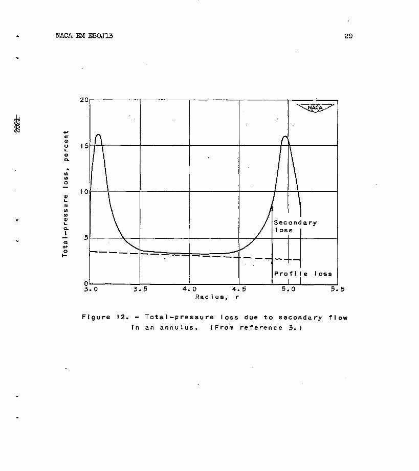
tie to the curvature in the flow through the blades, there is a . pressure @adzLent fn the gas stream from the convex surface of one blade toward the concave surface of the next blade. Owing to the boundary layer along inner and outer walls, the velocity of the gas near the boundary layer is lower and, consequently, the pressure gradient from the convex surface to the concave surface is correspondingly lower. Hence, the gas pressure at the concave Burfacenear the walls is less than that at the midspan of the blade, where- the gas pressure at the _ convex surface near the walls is higher than that at the mid8pan of the blade. Consequently, a secondary flow such as 8hOwII in figure U is. set up. Because they are unstable, the vortices roll up into two trail- ing vortices. This phenomenon can also be explained through the sudden drop of circulation in the snnulus boundary layer, thereby shedding trailing vortices. For relatively thin boundary layers, these two rolled-up vortices Eve close to the walls. Its essential effect i6 to give high losses near the end walls (fig. 12) and reduce the effective incidence to the blade and, consequently, the lift and the deflection (ffg. 13). Based on lifting-line theory, simple approximate formulas were obtained by Carter and Cohen (reference 3) for the induced inci- dence at the midspan and the induced drag coefficient:
(23)
where br is the distance between the two vortices to be determined experimentally.
Eausmann (reference 20) investigated induced flow in s cascade and obtaIned a more general expression for the value of downwash velocity. His numerical result shows that induced deflection angle rapidly - increases with boundary-layer displacement thicwss and decreases Slightly with the number Of blades,

.
14 NACABM E50313
TIP-(IXXAMNCE LOSS f
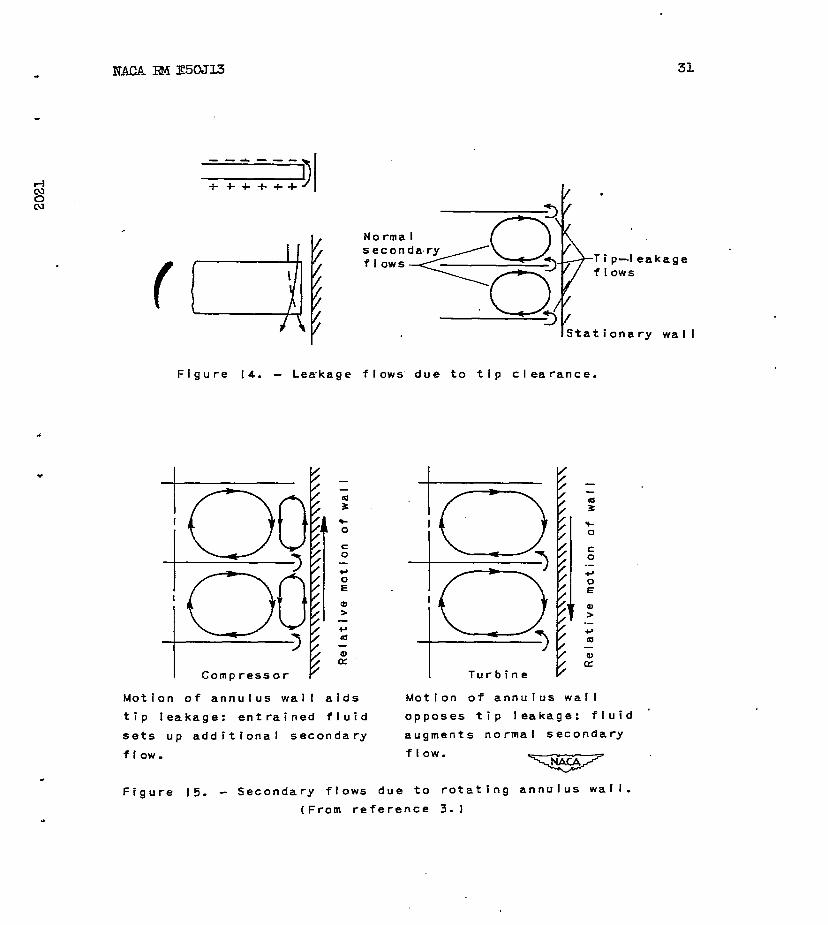
In the clearance space between the blade and the casing wall, gas flows from the pressure surface of the blade to the suction surface. Consequently, the streamline on the pressure side .has an additional velocity component toward the clearance space, whereas-the streamline on the euction side has an additional velocity away from the clearance space (fig. 14), giving a surface of discontinuity of velocity at the trailing edge. If the tip clearance lies within the boundary layer, the effect caused by this leakage flow is felt through a modification of the boundary-layer thickness or the value b' in equations (22) and (23). The separation of the tip-leakage loss from the induced flow associated with wall boundary layer is difficult. The tip-leakage loss is further complicated by the relative motion of the wall, which strengthens tfp-leakage flow in the cas.e of the compressor, whereas it opposes the tip-leakage flow in the case of the turbine (figs. l.5 and 16).
In spite of these complications, the theoretical effect of tip leakage alone is useful to help analyze the problem. As early as 1925, Eetz (reference 21) obtained the following expression for the minimum induced drag due to tip leakage (based on classical airfofl theory of small deflection):
+
b2 '
where
and
, (24)
(25)
(26)
An approximate expres-sion of k2 IS given by Meldahl (reference 22) as
1 ( C loge2 k2" z s CO8 a2 )
+- x .
(27)

NACA HM E3OJl3 15
Meld&l's tests on single-stage reaction turbines indicate an approxi- mately linear varfation of efficiency with tip clearance and suggest the percentage flow loss @;e and work loss 2, in the followfng formula for efficiency as a linear function of the ratio of tip clear- ance to blade width:
9 = rip - 2,
b/C, (28)
In the blade tested,
2, = 0.1011 + 4.667 c/Ca (29) .
@;e = -0.0422 + 2.790 c/C, (30) .
For c/C, varying between 0.04 and 0.08, the loss attributed to the clearance is about three-quarters of the total induced loss.
+ An investigation by Euden (reference 23) on a single-stage com-
pressor also indicate5 an approximately lfnear variation of efficiency with tip clearance.
l ANAPPROXIMATEcN6R-ALGPICTUHEOF
JDTERNAL FLOW LOSSNS
Considering the blade-profile loss the seme as in the two- dimensional cascade investigation, an annulus friction loss as that given by Howell, and the remaining losses as the secondary-flow 1055, a general picture of the variation of losses in a typical com- pressor and turbine is shown in figures 17 and 18, respectively. Although the division between the profile loss and the secondary-flow loss in the actual machine is inconclusive, it is apparent that the future improvement in efficiency and performanc e will be gained through the improvement of blade-design technique, so that the blade till operate at the mst desirable incidence angle, and the reduction in secondary losses frcm various sources.
. .
Lewis Flight Propulsfon Laboratory, National Advisory Committee for Aeronautics,
Cleveland, Ohio.

16 NACA~~E5OJl.3 l .-
REZEKENCES .-
1. Wu, Chung-Eua, and Wolfenstein, Lincoln: Application of Radial- Equilibrium Condition to Axial-Flow.Compressor and Turbine Design. NACA Rep. 955, 195d. (Formerly NACA TN 1795.)
2. Tsien, Hsue-Shen: Loss in Compressor or Turbine Due to Twisted Blades. C.I.E. Jour., 1947, pp. 40-53.
3. Carter, A. D. S.: Three-dimensional-flow Theories for Axial Compressor and Turbines. War,Emergency Issue No. 41, pub. by Inst. Mech. Eng. (London). (Reprinted in U.S. by ASME, April 1949, pp. 255-268.)
4. von K&m&, Theodore, -and Tsien, Hsue-Shen: Lifting-Line Theory for a Wing in Non-UniformFlow. Quart. Appl. Math., vol. III, ' no. 1, Apri11945, pp. l-11.
5. Hawthorne, William R.: Secondary Circulation in Fluid Flow. G135 Turbine Lab., M.I.T., May 1950.
6. Keller, C.: Kinetic Energy Losses behind Blade Grids-as a Result of Periodic Variation in the Circulation. Rep. Inst. Aero., Tech. Hochschule (Zurich), 1934, pp.'167.-187. (Available as R.T.P. Trans. No. 1883, British M.A.P.)
7. Loitsianskii, L. G.: Resistance of a Cascade of Airfoil5 in a Gas Flow with Subsonic Velocities. NACA TM 1303, 1950.
8. Squire, H. B., and Young, A. D.: The Calculation of the Profile Drag of Aerofoils. Rt & M. No. 1838, British A.R.C., Nov. 1937.
9. Ainley, D. G.: -Performance of Axial-flow Turbines. War Emer- gency Issue No. 41 pub. by Inst. Mech. Eng. (London). (Reprinted in U.S. by ASME, April 1949, pp. 230-244.)
10. Howell, A. R.: The Present Basis of Axial Flow Compressor Design. Part I. Cascade Theory and Performance. R. & M. No. 2095, British A.R.C., June 1942. '
Il. Howell, A.R.: The Aerodynamics'of the Gas Turbine. R.A.S. Jour., vol. LXX, 1948, pp. 329-348; discussion, pp. 348-356.
3 NACA RM EOJl3 17
w 12. Coldstein, Arthur W., and Mager, Artur: Attainable Circulation about Airfoils in Cascade. NACA Rep. 953, 1950. (Formerly
. NACA TN 1941.)
l-l 0” cu
13. S&ensen, E.: Wandrauhigkeitseinfluss bei Str%ungsmaschinen. Forschung auf 'dem Cebiete des Ingenieurwesens, Bd. 8, Heft 1, Jan./Febr. 1937, S. 25-29.
14. Betz, A.: Axial Superchargers. NACA TM 1073, 1944.
15. Weske, J. R.: Investigation of Blade Characteristics. Trans. A.S.M.E., vol. 66, no. 5, July 1944, pp. 413-418; discussion, pp. 419-420.
16. Weske, John R.: Fluid Dynamic Aspects of Axial-Flow Compressors and Turbines. Jour. Aero. Sci., vol. 14, no. 11, Nov. 1947, pp. 651-656.
17. Weske, J. R.: Secondary Flows in Rotating Blade Passages at High Reynolds Numbers. Proc. Seventh In-t. Cong. for Appl. Mech., vol. 2, pt. 1, 1948, pp. 155-163.
18. Burgers, J. M.:' Some Considerations on the Development of Boundary Layers in the Case of Flows Having a Rotational Component. Nederl, Akad. van Wetenschappen, vol. XLIV, Nos. l-5, 1941, pp. 12-25.
19. Eckert, B., PflGger, F., and Weinig, F.: The Influence of the Diameter Ratio on the Characteristics Diagram of the Axial Compressor. NACA.TM 1125, 1948.
20. Bausmann, George F.: The Theoretical Induced Deflection Angle in Cascades Raving Wall Boundary Layers. Jour. Aero: Sci., vol. l5, no.' 11, Ndv. 1948, pp. 686-690.
21. Betz, A.: Gber die Vorg&ge an den Schaufelenden von Kaplan- Turbinen. Ein Wissenschaftlischer tjberblick Vortrage auf der Bydraliketagung (C&tingen), AM 5 und 6, J&i 1925, S. 161-179.
22. Keldahl, A.: End Losses of Turbine Blades. Jour. Am. Sot. Naval En@;., vol. 54,.no. 3, Aug. 1942, pp. 454-466.
23. Ruden, P.: Investigation of Single Stage Axial Fans. NACA TM 1062, 1944.

t-ts-i N w P
.
Figure 1. - Loss due to -unsteady flow.

c l 2021 1 I
.70
? ii 0 .- 0 .- :
.76
0
‘p L
a .74 > 0
Y RI
c?
.72
,7a
T I b 1 3 n
d II
Design total-
. ID .20 .3D .40 .5D Stator-rotdr axial clearance, in.
.60 .70
Figure 2. - Turbine peak efficiency plotted against axial clearance for model reaction turbine. (From unpubllshed data ol’ Wright Aeronautical
Corporation. 1 iii

20 NACA RM E5OXL3
wl,.J wm
!- -w2 I-
cx -0
\ R
\
rwm L 3 f$
\
,‘a 2 --_m D
few, - x
I? / ‘am I
\
-- --x
D
L
\
R. J
\
ICI
‘2 - - w /k” w2,c4
Figure 3. - Resistance of al rfoi I in cascade.

. IiACA F&f E5CKt.3
.
.30
.20
. IO
. 08
.O6
-04
. 03
-02
. 01 .
21
I I.
Va tues deduced from four-stage. v
low-pressure reactlon turbine-/ /‘r9, -- .300
1 I . 2 .3 .4 .6 .8- 1.0 2.0 3. Reynolds number
(Based on outlet gas flow from blades)
oxto
Figure 4. - Variation of profile loss with
Reyno Ids number. (From reference 9. 1

22 NAOA RM E5OJl3 c
I.
I.
0” .
; c a .- U
.- Y- l
‘c
:
u
t t
.-
-1 l
.
.
----
0
8 .20
6 .I 5
4 .I 0
2 .o 5
I -90
I I I I I I I I I -5 0 5 IO I 5O
Incidence, deg
Figure 5. - Typlcal compressor cascade results.
(From reference I I. 1
$1 = 550 82 = 3oa
a/C = 0.4 s/c = 0. 7’5’
8 - 250 t/c = LO percent
-
7

RME5oJl3 RME5oJl3 23
f f I I 1 1 I I Impulse blade Impulse blade -- -Reaction blade -- -Reaction blade
PI - 45.50 PI - 45.50 $2 $2 = -45.8’ = -45.8’
@, = t8.9O @, = t8.9O - -47. I0 - -47. I0
s/c = 0.625 s/c = 0.625 S/C 82 - 0.58 - S/C 82 - 0.58 - t/c = t/c = 22 percent 22 percent t/c = t/c = cos-lo/S’ -500 cos-lo/S’ -500 15 15 percent percent
cos cos “O/S = -500 “O/S = -500
r- Gas out tat angle Gas outtat angle
I I _. _.
z - : .24. 24. .’ .’
E E Lo Lo b b 0 0
- + Y a 2 0
= ‘3 +r :! .20. 2 0‘. 0
of; tq
+ z a - - 5 + .I6
z 16
3 ‘;; Prof f le-loss Prof f le-loss
0 c, coeff icl ent coeff icl ent ri? 0
cr .I2 1, I2 1,
; 0’ 0 008 08 L:
!a
n --, --, 0” - .04. - 04. :
-30 -20 -to 0 to 20 30 Incidence, deg
Figure 6. - Variation in profite toss with in- cidence for typical turbine blades. Base profi Ie, T.6; a/C = 43 percent; Reynolds number *1.5x10⁵; Mach number at outletfi0.5-
IFram reference 9. 1

0
I W
I .
-20 0 20 Incidence, deg
(ali Impulse blade,;’
cos -'O/s = -60’
gp2 = -0.97
s/c = 0.627 t/c = 31.3 percent 1
Figure 7. - Variation of blade loss with Mach number. (From
0 20 Incidence, deg
(b) Reaction blade.
cos -‘o/s - 40°
f11/a2 = -0.33 s/c = 0.551 t/c = 18. I percent
reference 9. I

NACA RM E5OJl.3 25
.
.
.
2 ;;
u x .
.
16
12
08
0 .8 I.2 1.6 2.0
CLW2 ,‘A v . Figure 8. - Lift and drag coefficients based on
outlet velocities. (From referen'ce II.1
x = 6(S/C) -I ~ 6 -CT
SLS/CI 5

26 NACA FiM Ft5CJl.3 t
Agl -.
0 Compressor 5 (approximately)
Cl Turbine 42 (total loss over whole blade length)
-A Turbine 42 (IoSS over center port ion of blade)
I Theoretical loss
I I I . 02 .O4 .06 .08
Trai I ing-edge thickness Blade pitch
1.0
-?v-
Flgure 9. - Effect of trai I ing-edge thick-
ness on blade-profile loss. I Reeman and
Simonis. 1

32
2021
.3O
O'lncidence
L ine of survey
2 al
T” ; .- 6;
45
40
35
30
Thermal efficiency - 0.905 ! 0.920
Exit Mach number 0.747 0.756
0.951.
0.763
Figure IO. - Variation of wake profile and loss
0.961
0.761
w,ith different
trailing-edge thickness and taper. (From unpublished data
of Wright AeronauticpI Cornoration.)

28 NACA RM E5OJ-U
Plane. containing
trai I ing edges
r = Circulation around center
of blade = strength of
each tral I ing vortex
(From reference 3. 1
b” Distance between vortices
2 span of equivalent
blade of constant
circulation
-- --Secondary ftows
C Vort ices
Figure II. - Secondary flows in cascade.
I
---
29
1 A I t
Secondary
5
01 3.0 3.5
I 4.0
I t ProfT!e loss
I I 4.5 5.0 5.5
Radius, r
Figure 12. - Total-pressure loss due to secondary flow
in an annulus. (From reference 3. 1

30 NACA IBM E5OJl3
.
0 1.0 2.0 3.0 4.0, Root Blade height, in. TOP
Figure 13. - Variatlon of outlet angle alon
blade -height. Pitc’h/chord, 1.0. 1 From
reference 3. 1
9
NACA EM E5cm.3 31
No t-ma secon fIows -T i p--leakage
fl ows
IStat i
Figure 14. - Leakage flows due to tip clearance.
I Turbine
onary wal I
Mot Ion of annufus wal I aids Motion of annulus wall
tip leakage: entrained fluid opposes tip leakage: fluid ’
sets up additlonal secondary augments normal secondary
flow. flow. -
Figure 15. - Secondary flows due to rotating annulus wall.
(From reference 3. I

I-
I
I I
I /-
Loss due to scrubbing
effect of rotating
wa.l I
Radius, r
.o
Root
Figure 16. - Total-pressure losses due to secondary flow in xompressor.
(From reference 3. 1
’ I
‘I I
. II

NACA RM E5OJl3 33
1.00
.90 E”
; 0 z 0 .80 F r aI 0 ul a =: .70
.6(1 ;
t : c
Percent
12.2 I
'* .4 Annulus 109s
I I
.7
. Annulus ptus secondary plub proflIe-
I I .9 I. I 1.3 1.5
Flow coefficient, V,/U
Figure 17. - Varlatron of Iosses with flow co.efficfents In a compressor. IFrom referen'ce 3. 1

. I
. I
Total bver-al I
444 Toss coeffic”fent
Profile
IO 20 30
Incidence, deg
Figure 18. - Analysis of energy losses in flow through
row of turbine blades. (From reference 9.1
I . I

--.- -..- - --. - ._ 31176014350194 :. : 2 :.
!I
i
k.. :
_.- ._--.-, .,
t
”
. f
t
i

.
‘c
s-c -.- .._
c---- --
.
~ . - -
. I