Ultra Wideband Coplanar Waveguide Based Impedance Transformer with Slow-wave Electrodes
Research ArticleCoplanar Waveguide-Fed Broadband MicrowaveDevices with (or without) a Thin Dielectric Substrate forUse in Flexible Electronic Systems
Rafal Lech, Wojciech Marynowski, Adam Kusiek, and Jerzy Mazur
Department of Microwave and Antenna Engineering, Gdansk University of Technology, Narutowicza 11/12, 80-233 Gdansk, Poland
Correspondence should be addressed to Rafal Lech; [email protected]
Received 7 October 2013; Revised 22 November 2013; Accepted 1 December 2013; Published 6 January 2014
Academic Editor: Giuseppe Mazzarella
Copyright © 2014 Rafal Lech et al. This is an open access article distributed under the Creative Commons Attribution License,which permits unrestricted use, distribution, and reproduction in any medium, provided the original work is properly cited.
Two examples of microwave devices, fed by a coplanar waveguide and realized on a thin substrate (or without such a substrate), areemployed to investigate the influence of devices’ curvatures and the proximity of differentmaterials on their parameters. To performthe tests, a broadband antenna and a low-pass filter are chosen. A feeding coplanar waveguide is realized on a dielectric materialbrick attached to an SMA connector and themain device structure is placed in the air or on a thin substrate.The utilization of a thinsubstrate or its removal from the structure gives rise to the possibility of placing the devices on curved surfaces. The investigateddevices are redesigned and manufactured. The antenna has a total size of 46mm × 44mm and covers a frequency range of 2.4–35GHz which gives a 174% fractional bandwidth. The filter has a total size of 50mm × 80mm and its bandwidth has a cutofffrequency of 3.4GHz. The obtained results are verified by measurements and good agreement is achieved.
1. Introduction
The microwave components, including antennas and filters,used in mobile devices should not only operate within aspecific frequency range but also have a compact and simplestructure, with slight dimensions and a light weight. Besidesthe above requirements, their production costs, especially forlarge scale production, should also be as low as possible.When the device is designed on a thin and flexible layer,it can be bent and placed on curved surfaces. Conformalcomponents (antennas especially) are becoming populardue to their many advantages and the possibilities of theirapplication [1].The advantages of using devices with a curvedsurface arise from the possibility of integrating themwith theobject on which they are mounted. In the case of conformalantennas, the particular advantage is the increase—relativeto the planar antenna—of their visible angular range. Theconformal devices find application in a variety of fields,such as airborne, space-borne, ship-borne and missile-borneradar, space vehicles, wireless communication, and sonar.Besides the conformability of the flexible devices, they canfind application and are becoming popular in the field
of flexible electronics [2, 3]. The main requirements forsuch devices are light weight, low-cost manufacturing, easeof fabrication, and the availability of inexpensive flexiblesubstrates (i.e., papers, textiles, and plastics). Many flexibleantenna structures have been proposed in the literature (e.g.,textiles with conducting threads [4] and paper-based [5],fluidic-based [6], and ink-jet printed antennas [7]).
In this paper, we investigate the modified version of twomicrowave devices. The first one is a broadband coplanarantenna proposed in [8, 9] with reduced dimensions, whilethe second one is a low-pass filter, the structure of which wasproposed in [10]. In both cases, the modifications considerboth the reduction and the absence of a dielectric substrate.The main goal of this work is to investigate the influence ofdevices’ curvatures and the proximity of different materialson their performance. Both devices are designed to be fedby a coplanar line on a short brick of a dielectric layer, andthe main body of the device is placed in free space (thedielectric substrate is removed). In order tomanufacture sucha structure, we utilize electrically-conductive adhesive tape.The designed devices are produced with the use of a laserstructuring system. Commercial software is used to simulate
Hindawi Publishing CorporationInternational Journal of Antennas and PropagationVolume 2014, Article ID 379379, 9 pageshttp://dx.doi.org/10.1155/2014/379379

2 International Journal of Antennas and Propagation
t
ts
x
y
y
z
Thin substrate (optional)MetalDielectric
w1w1 w0 s0s0
wb
l
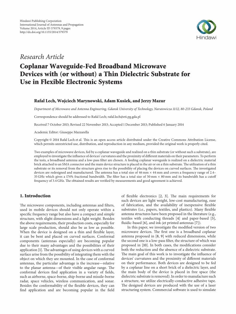
Figure 1: Geometry of the feeding line.
53
52
51
50
49
48
470 5 10 15 20 25 30 35 40
Resis
tanc
e (Ω
)
Frequency (GHz)
Antenna feeding lineFilter feeding line
Figure 2: Calculated input impedance of the coplanar waveguidefrom Figure 1.
the performance of the devices. The obtained results areverified by our measurements of manufactured prototypes.
2. Geometry of the Devices
Here, we present the schematic configurations of the investi-gated devices with their feeding lines and the manufacturingprocess used for the prototypes’ realization. In Section 2.1, thedescription of a feeding line and a manufacturing process ispresented. The antenna structure is described in Section 2.2,while the configuration of a filter is presented in Section 2.3.
2.1. The Feeding Line and Manufacturing Process. Theschematic configuration of the feeding line is presented inFigure 1. In order to provide 50Ω characteristic impedanceof the coplanar waveguide for feeding the devices, the line hasthe dimensions 𝑤
0= 3.5mm, 𝑠 = 0.25mm, 𝑤
1= 9mm (in
the case of the antenna structure) and 𝑤1= 22mm (in the
case of the filter structure), and is realized on a short brick ofa dielectric material with a thickness 𝑡 = 1.07mm, a width𝑤𝑏= 10mm, and a length 𝑙 = 3.8mm, with a permittivity𝜀𝑟= 3.44. The dimensions of the brick correspond to the
dimensions of the SMA connector used.The calculated inputimpedances of these lines (for the antenna feed and the filterfeed) are shown in Figure 2. In the case of the filter structure,only the frequency range from 0GHz to 10GHz is takeninto consideration, while in the case of the antenna the lineimpedance is calculated up to 40GHz. As can be observed,the impedance is almost frequency-invariant, and it onlychanges by about 3.8Ω within a frequency range of 0GHzto 40GHz.
To fabricate the prototypes of the devices, we utilize anelectrically-conductive adhesive tape with a copper thicknessof 0.12mm and a paper thickness of 𝑡
𝑠= 0.08mm as well
as a laser structuring system. The laser cuts the structuregeometry on the tape (as seen in the case of the antenna inFigure 3(a)) and after this procedure the redundant tape canbe easily removed (see Figure 3(b)), resulting in the requiredstructure geometry presented in Figure 3(c).
The dielectric brick was realized with the use of adielectric substrate placed under the feeding line and held bythe SMA connector, as shown in Figure 4.
2.2. Antenna Structure. Various designs of planar antennashave been made to increase their bandwidth [8, 9, 11–17].The reported antenna monopoles have rectangular [12, 17],circular [8, 9], or elliptical [11, 16] shapes, and they can be fedby a coaxial cable or else by coplanar or microstrip lines. Forthese examples, a bandwidth of several gigahertz is achieved.Most designs utilize a thick, nonflexible dielectric material asan antenna substrate, which does not allow for its bendingor application to curved surfaces. The coaxial cable-fedelliptical ring antenna reported in [16] was designed withoutthe utilization of a substrate material, which allowed theobtaining of a bidirectional, symmetrical radiation pattern.
To test the influence of antenna curvature and theproximity of different materials on its performance, theantenna design proposed in [9] was employed.The schematicconfiguration of the antenna is presented in Figure 5. Thestructure is fed by a coplanar waveguide. The center strip ofthe line is terminated at a circular patch of radius𝑅
𝑝enclosed
by a circular slot of radius 𝑅𝑠etched into the circular ring
of a ground plane of width 𝑅𝑜− 𝑅𝑠. A frequency notch in
the antenna can be realized by a circular slot etched into theantenna patch. The slot is of width 𝑠
𝑛and length 𝐿
𝑛, with a
separationwidth𝑤𝑛and a displacement from the patch center
𝑑𝑛.As was reported in [9], the selection of a proper value
of the circular patch radius 𝑅𝑝ensures the acquisition of
the impedance matching between the feeding line and theslot within the entire frequency range. The value of theinner slot radius 𝑅
𝑠influences the antenna operation only in
the low frequencies. The slot offset 𝑑𝑠mainly affects higher
frequencies in the antenna bandwidth. The choice of theouter radius Ro of the ground plane circular ring allowsfor the control of the reflection characteristic slope at low

International Journal of Antennas and Propagation 3
(a) (b) (c)
Figure 3: Photographs of manufactured antenna on a copper adhesive tape.
Figure 4: Photographs of the SMA connector and the brick underthe feeding line.
Rs
Rp
dn Ln
ds x
y
Thin substrate (optional)MetalDielectric
wn
sn
RO
Figure 5: Geometry of the antenna.
frequencies. The narrower the width of the ground planecircular ring, the higher the slope of the antenna reflectioncharacteristic. To demonstrate this effect, the calculation ofthe slope width as a function of the ground plane circular ringwidth is performed and presented in the results section of thispaper.
2.3. Filter Structure. The schematic configuration of the filteris presented in Figure 6. The structure consists of a transmis-sion line with short-circuited series stubs. The stubs are of
W1 W2 W3
Scigci
Thin substrate (optional)MetalDielectric
l3l2l1
lci
l2,3l1,3
Figure 6: Geometry of the filter.
length 𝑙𝑖and width𝑊
𝑖for 𝑖 = 1, 2, 3. The distances between
the stubs are 𝑙1,2
and 𝑙2,3. At the connection points between the
coplanarwaveguide and the slot lines, the compensated cross-junction is utilized tominimize the unwanted parasitic effect.The cross-junction structure is constructed with a narrowedstrip conductor with a width 𝑠
𝑐𝑖and length 𝑙
𝑐𝑖.
3. Results
The scattering parameters of the manufactured devices weremeasured using an Anritsu/Wiltron 37269A VNA NetworkAnalyzer, and the radiation patterns of the antenna weremeasured in an anechoic chamber using an Agilent E5071CENA Network Analyzer with a GeoZondas UWB AU-3.1G10.6G-1 antenna for measurements at 4GHz and 6GHzand a waveguide horn antenna EMCOModel no. 3160-07 formeasurements at 10GHz.
3.1. Antenna Structure. In order to demonstrate the accuracyof the proposed fabrication process, we designed, manu-factured and measured four broadband antennas with thedimensions listed in Table 1.

4 International Journal of Antennas and Propagation
2 4 6 8 10 12Frequency (GHz)
Antenna 10
−5
−10
−15
−20
−25
−30
Antenna 2
2 4 6 8 10 12Frequency (GHz)
0
−5
−10
−15
−20
−25
−30
Antenna 3
2 4 6 8 10 12Frequency (GHz)
0
−5
−10
−15
−20
−25
−30
Antenna 4
2 4 6 8 10 12Frequency (GHz)
0
−5
−10
−15
−20
−25
−30
Mag
nitu
de
(dB)
SM
agni
tude
(d
B)S
Mag
nitu
de
(dB)
SM
agni
tude
(d
B)S
Figure 7: Magnitude of the reflection coefficient for planar antennas. Simulation: solid line. Measurement: dashed line.
Table 1: Dimensions of the designed antennas. All dimensions arein millimeters.
𝑅𝑜
𝑅𝑠
𝑅𝑝
𝑑𝑠
Antenna no. 1 21 16 9.5 0.15Antenna no. 2 21.5 16 9.5 0.2Antenna no. 3 21.5 16 8.5 0.2Antenna no. 4 22 18 10 0.1
To obtain the antenna dimensions, commercial electro-magnetic software was used to simulate and optimize thestructure. The simulated and measured characteristics ofthe reflection coefficients versus frequency are illustrated inFigure 7.
As can be observed from the results, the simulatedand measured characteristics for each antenna are in goodagreement with each other, which validates the proposedrealization technique.
For further investigation, we considered only antenna no.4. The lack of a thick dielectric substrate below the radiatorallows for the bending of the antenna, as shown in Figure 8,in order to place it on a curved surface.
First, the investigation of the reflection coefficient char-acteristic slope width Δ = 𝑓(|𝑆
11| = −10 dB) − 𝑓(|𝑆
11| =
−3 dB) as a function of the ground plane circular ring width𝑤𝑔= 𝑅𝑜− 𝑅𝑠is performed. The slope width Δ is defined
as a difference of frequencies at which the magnitude of thereflection coefficient takes the values −3 dB and −10 dB. Theresults are calculated for the planar and curved cases of theantenna and are presented in Table 2.
As can be seen, the narrower the width of the groundplane circular ring, the higher the slope of the antennareflection characteristics. Therefore, the choice of radius 𝑅
𝑜
can be used to adjust the slope of the reflection coefficientcharacteristics.
Next, the measurement of the antenna reflection coeffi-cients for the planar and curved cases was performed, withthe results presented in Figure 9.

International Journal of Antennas and Propagation 5
(a) (b)
(c) (d)
Figure 8: Photographs of the fabricated antenna: (a) planar version on paper, and (b) planar version in air, (c) curved around the 𝑥-axis, (d)curved around the 𝑦-axis.
Table 2:The slope widthΔ (MHz) as a function of the ground planecircular ring width 𝑤
𝑔= 𝑅𝑜− 𝑅𝑠for antenna no. 4. The width of
the ground plane circular ring is regulated by changing the radius𝑅𝑜with the other dimensions unchanged. The curvature radii 13 cm
and 30 cm were assumed for the antennas curved around the 𝑥-axisand the 𝑦-axis, respectively.
𝑤𝑔(mm) 1 4 7 10 12
Δ-planar case 380 412 470 556 708
Δ-curved 𝑥-axis 292 293 319 412 657
Δ-curved 𝑦-axis 307 410 532 584 607
As can be seen, the planar version of the antenna operateswithin a frequency range of 2.4–35GHz with a reflectioncoefficient lower than −10 dB (which gives a 174% fractionalbandwidth). In the case of bending the antenna aroundthe 𝑦-axis, the operation frequency is limited to 30.7GHz.Removing the paper substrate slightly deforms the antennastructure and, in this case, the upper frequency is limitedto 29.5GHz. The discrepancies between the simulated and
Table 3: Dimensions of the resonators realizing the frequencynotch. All dimensions are in millimeters.
𝐿𝑛
𝑠𝑛
𝑤𝑛
𝑑𝑛
Notch at 5GHz 13.5 0.3 0.6 4
Notch at 6GHz 11 0.3 0.6 5
measured results at higher frequencies may be due to theSMA connector.
When realizing the antenna with a frequency notch onthe adhesive tape, the parameters of the paper need to betaken into account, as they may affect the resonance of thenotch. The paper is of thickness 𝑡
𝑝= 0.08mm and its
permittivity was determined experimentally to be 𝜀𝑟= 2.9.
Two antennas with notches at frequencies 5GHz and 6GHzwere designed and manufactured. The dimensions of theresonator are presented in Table 3.
The results of the reflection coefficients for the antennawith a notch are presented in Figure 10. As can be observed,the influence of the paper is clearly visible, as the resonance

6 International Journal of Antennas and Propagation
Frequency (GHz)
0
−5
−10
−15
−20
−25
−300 10 20 30 40
Planar on paperPlanar on paperPlanar on air
Mag
nitu
deS 1
1(d
B)
Curved around x-axisCurved around y-axis
Figure 9: Magnitude of the reflection coefficient for the planar and curved antennas, as shown in Figure 8. Simulation: solid line.Measurement: dashed line.
Antenna without paper tapeAntenna on paper tape
4 5 6 7 8
Frequency (GHz)
Mag
nitu
de
(dB)
0
−10
−15
−20
−25
−5
−30
Antenna without paper tapeAntenna on paper tape
4 5 6 7 8
Frequency (GHz)
0
−10
−15
−20
−25
−5
−30
S
Mag
nitu
de
(dB)
S
Figure 10: Magnitude of the reflection coefficient for a planar antenna with a notch at frequencies: (a)𝑓 = 5GHz, (b)𝑓 = 6GHz. Simulation:solid line. Measurement: dashed line.
of the notch is shifted in both cases by about 500MHz incomparison to the antennas without the paper tape.
The antenna without the notch was next attached toseveral different materials, such as a wooden desk (𝜀
𝑟≈
2) of thickness 3 cm, plastic foil (𝜀𝑟≈ 2.5) of thickness
0.13mm, window glass (𝜀𝑟≈ 4.8) of thickness 5mm, a
human arm, and a cylindrical PCV pipe (𝜀𝑟≈ 3) of radius
5 cm and thickness 2mm. The antenna reflection coefficientwas measured within the frequency range of 0GHz up to15GHz, and the results are presented in Figure 11. As can beseen, the proximity of these materials slightly increases theantenna reflection coefficient; however, it does not signifi-cantly change the antenna performance.
Finally, the fabricated antenna was measured in an ane-choic chamber at frequencies of 4GHz, 6GHz, and 10GHz,and the results were compared with those obtained fromthe simulations. The radiation patterns for the investigatedantennas are presented in Figure 12. As can be seen, goodagreement between the simulations and the measurementswas achieved.
3.2. Filter Structure. The filter proposed in [10] was redesign-ed to the structure situated on the paper substrate. Theobtained dimensions are as follows: 𝑙
1= 𝑙2= 𝑙3= 11.4mm,
𝑊1= 𝑊3= 0.11mm,𝑊
2= 0.45mm, 𝑙
1,2= 𝑙2,3= 22.8mm,

International Journal of Antennas and Propagation 7
0
−5
−10
−15
−20
−25
−300 5 10 15
Frequency (GHz)
Simulation (planar)
Measurement (antenna on wooden desk)Measurement (planar-stand alone)
Measurement (antenna on thin plastic foil)Measurement (antenna on window glass)Measurement (antenna on human arm)Measurement (antenna on cylindrical PCV pipe)
Mag
nitu
deS 1
1(d
B)
Figure 11: Magnitude of the reflection coefficient for the investigated antenna placed on different materials.
SimulationMeasurement
SimulationMeasurement
SimulationMeasurement
x
y
z
0∘
15∘
30∘45∘
60∘75∘105∘
120∘
135∘
150∘
165∘
±180∘
−15∘
−30∘
−45∘
−60∘
−75∘−90∘
90∘
−105∘−120∘
−135∘−150∘−165∘ −165∘
0∘
15∘
30∘45∘
60∘75∘105∘
120∘
135∘
150∘
165∘
±180∘
−15∘
−30∘
−45∘
−60∘
−75∘−90∘
90∘
−105∘−120∘
−135∘−150∘
−165∘
0∘
15∘
30∘45∘
60∘75∘105∘
120∘
135∘
150∘
165∘
±180∘
−15∘
−30∘
−45∘
−60∘
−75∘−90∘
90∘
−105∘−120∘
−135∘−150∘
−165∘
0∘
15∘
30∘45∘
60∘75∘105∘
120∘
135∘
150∘
165∘
±180∘
−15∘
−30∘
−45∘
−60∘
−75∘−90∘
90∘
−105∘−120∘
−135∘−150∘
−165∘
0∘
15∘
30∘45∘
60∘75∘105∘
120∘
135∘
150∘
165∘
±180∘
−15∘
−30∘
−45∘
−60∘
−75∘−90∘
90∘
−105∘−120∘
−135∘−150∘
−165∘
0∘
15∘
30∘45∘
60∘75∘105∘
120∘
135∘
150∘
165∘
±180∘
−15∘
−30∘
−45∘
−60∘
−75∘−90∘
90∘
−105∘−120∘
−135∘−150∘
Figure 12: Radiation patterns of the antenna at frequencies 4GHz, 6GHz, and 10GHz. First column: 𝑦𝑧 plane for 𝑥 = 0, second column: 𝑥𝑧plane for 𝑦 = 0. Simulation: solid line. Measurement: dashed line.
𝑠𝑐1= 𝑠𝑐3= 2.28mm, 𝑠
𝑐2= 2.23mm, 𝑙
𝑐1= 𝑙𝑐3= 0.17mm, and
𝑙𝑐2= 0.33mm.Also, in this case, the lack of a thick dielectric substrate
below the structure allows for the bending of the filter, asshown in Figure 13.
The simulated and measured characteristics of the scat-tering parameters versus frequency are illustrated in Figures14 and 15.
As can be observed from the results, bending the filterdoes not significantly change its scattering parameters. The

8 International Journal of Antennas and Propagation
(a) (b) (c)
Figure 13: Photographs of the fabricated filter: (a) planar version, (b) curved along its length, and (c) curved along its width.
0
−5
−10
−15
−20
−25
−30
−35
−4020 4 6 8 10 12
Frequency (GHz)
PlanarCurved 45∘along widthCurved 90∘along length
Curved 180∘along lengthCurved on PCV pipe r = 4 cm
Mag
nitu
de
(dB)
S
Figure 14: Simulatedmagnitude of the scattering parameters for thefilter in its planar and curved version. 𝑆
11: solid line. 𝑆
21: dashed line.
0
−5
−10
−15
−20
−25
−30
−35
−4020 4 6 8 10 12
Frequency (GHz)
PlanarCurved 45∘along widthCurved 90∘along length
Curved 180∘along lengthCurved on PCV pipe r = 4 cm
Mag
nitu
de
(dB)
S
Figure 15: Measuredmagnitude of the scattering parameters for thefilter in its planar and curved version. 𝑆
11: solid line. 𝑆
21: dashed line.
proximity of other materials will affect its performance as theelectric lengths of the stubs and lines are changed. Placing thefilter on the PCV pipe (𝜀
𝑟≈ 3, radius 5 cm, thickness 2mm)
lowered its cutoff frequency by about 270MHz.
4. Conclusion
The investigation of the influence of microwave devices’curvatures and the proximity of different materials on theirperformance was performed. Two examples of microwavedevices, a broadband antenna and a low-pass filter, wereemployed for the investigation. The devices were realized onadhesive copper tape. A lack of a dielectric substrate allowedfor the bending of the devices so as to place them on curvedsurfaces. The bending of the antennas and the proximity ofseveral different materials do not significantly affect theirperformance. In the case of the filter structure, the bendingdoes not affect its performance but the proximity of othermaterials changes the electrical lengths of the series stubsand lines, which has an influence on the filter parameters.In summary, the greater the broadband character of thedevice, the less sensitive it is to the proximity of othermaterials. In addition, as the device curvature or the othermaterial’s proximity may increase the reflection coefficientof the device, this effect should be taken into account inthe design process of the basic structure by setting slightlyrigorous design goals. The conducted investigations confirmthat the proposed antenna and filter structures can be realizedon thin (or without) substrates and that they can be utilizedin flexible electronic systems.
Conflict of Interests
The authors declare that there is no conflict of interestsregarding the publication of this paper.
Acknowledgments
This work was supported in part by National Science Centerunder Grant decision no. DEC-2011/01/D/ST7/06639 andby Polish Ministry of Science and Higher Education fromsources for science in the years 2012-2013 under Contract no.0340/IP2/2011/71.

International Journal of Antennas and Propagation 9
References
[1] L. Josefsson and P. Persson, “Conformal array synthesis includ-ing mutual coupling,” Electronics Letters, vol. 35, no. 8, pp. 625–627, 1999.
[2] A. Nathan and B. R. Chalamala, “Special issue on flexibleelectronics technology, part 1: systems and applications,” Pro-ceedings of the IEEE, vol. 93, no. 7, pp. 1235–1237, 2005.
[3] J. Hu, “Overview of flexible electronics from ITRI’s viewpoint,”in Proceedings of the 28th VLSI Test Symposium (VTS ’10), p. 84,Santa Cruz, Calif, USA, April 2010.
[4] S. Zhang, A. Chauraya, W. Whittow et al., “Embroidered wear-able antennas using conductive threads with different stitchspacings,” in Proceedings of the 7th Loughborough Antennas andPropagation Conference (LAPC ’12), pp. 1–4, Loughborough,UK, November 2012.
[5] D. E. Anagnostou, A. A. Gheethan, A. K. Amert, and K. W.Whites, “A direct-write printed antenna on paper-based organicsubstrate for flexible displays and WLAN applications,” Journalof Display Technology, vol. 6, no. 11, pp. 558–564, 2010.
[6] M. Kubo, X. Li, C. Kim et al., “Stretchable microfluidic radiofre-quency antennas,”AdvancedMaterials, vol. 22, no. 25, pp. 2749–2752, 2010.
[7] H. R. Khaleel, H. M. Al-Rizzo, and A. I. Abbosh, “Design,fabrication, and testing of flexible antennas,” in Advancementin Microstrip Antennas With Recent Applications, A. Kishk, Ed.,InTech, Vienna, Austria, 2013.
[8] T. A. Denidni and M. A. Habib, “Broadband printed CPW-fedcircular slot antenna,” Electronics Letters, vol. 42, no. 3, pp. 135–136, 2006.
[9] W. Marynowski and J. Mazur, “Design of UWB coplanarantenna with reduced ground plane,” Journal of ElectromagneticWaves and Applications, vol. 23, no. 13, pp. 1707–1713, 2009.
[10] R. Li, S. Sun, and L. Zhu, “Direct synthesis of transmissionline low-/high-pass filters with series stubs,” IET Microwaves,Antennas & Propagation, vol. 3, no. 4, pp. 654–662, 2009.
[11] E. S. Angelopoulos, A. Z. Anastopoulos, D. I. Kaklamani, A.A. Alexandridis, F. Lazarakis, and K. Dangakis, “Circular andelliptical CPW-fed slot and microstrip-fed antennas for ultraw-ideband applications,” IEEE Antennas andWireless PropagationLetters, vol. 5, no. 1, pp. 294–297, 2006.
[12] Y. F. Liu, K. L. Lau, Q. Xue, andC.H. Chan, “Experimental stud-ies of printed wide-slot antenna for wide-band applications,”IEEE Antennas and Wireless Propagation Letters, vol. 3, no. 1,pp. 273–275, 2004.
[13] M. E. Bialkowski and A. M. Abbosh, “Design of UWB planarantenna with improved cut-off at the out-of-band frequencies,”IEEE Antennas andWireless Propagation Letters, vol. 7, pp. 408–410, 2008.
[14] S.-W. Su, K.-L. Wong, and F.-S. Chang, “Compact printedultra-wideband slot antenna with a band-notched operation,”Microwave andOptical Technology Letters, vol. 45, no. 2, pp. 128–130, 2005.
[15] M. Chen and J.Wang, “Compact CPW-fed circular slot antennafor ultra-wideband applications,” in Proceedings of the 8thInternational Symposium on Antennas, Propagation and EMTheory (ISAPE ’08), pp. 78–81, Kunming, China, November2008.
[16] K. Chawanonphithak, C. Phongcharoenpanich, S. Kosulvit, andM. Krairiksh, “5.8GHz notched UWB bidirectional ellipticalring antenna excited by circular monopole with curved slot,”
in Proceedings of the Asia-Pacific Microwave Conference (APMC’07), pp. 1–4, Bangkok, Thailand, December 2007.
[17] D. Kumar, T. Singh, R. Dwivedi, and S. Verma, “A compactmonopole CPW-fed dual band notched square-ring antennafor UWB applications,” in Proceedings of the 4th InternationalConference on Computational Intelligence and CommunicationNetworks (CICN ’12), pp. 57–60, Mathura, India, November2012.

International Journal of
AerospaceEngineeringHindawi Publishing Corporationhttp://www.hindawi.com Volume 2014
RoboticsJournal of
Hindawi Publishing Corporationhttp://www.hindawi.com Volume 2014
Hindawi Publishing Corporationhttp://www.hindawi.com Volume 2014
Active and Passive Electronic Components
Control Scienceand Engineering
Journal of
Hindawi Publishing Corporationhttp://www.hindawi.com Volume 2014
International Journal of
RotatingMachinery
Hindawi Publishing Corporationhttp://www.hindawi.com Volume 2014
Hindawi Publishing Corporation http://www.hindawi.com
Journal ofEngineeringVolume 2014
Submit your manuscripts athttp://www.hindawi.com
VLSI Design
Hindawi Publishing Corporationhttp://www.hindawi.com Volume 2014
Hindawi Publishing Corporationhttp://www.hindawi.com Volume 2014
Shock and Vibration
Hindawi Publishing Corporationhttp://www.hindawi.com Volume 2014
Civil EngineeringAdvances in
Acoustics and VibrationAdvances in
Hindawi Publishing Corporationhttp://www.hindawi.com Volume 2014
Hindawi Publishing Corporationhttp://www.hindawi.com Volume 2014
Electrical and Computer Engineering
Journal of
Advances inOptoElectronics
Hindawi Publishing Corporation http://www.hindawi.com
Volume 2014
The Scientific World JournalHindawi Publishing Corporation http://www.hindawi.com Volume 2014
SensorsJournal of
Hindawi Publishing Corporationhttp://www.hindawi.com Volume 2014
Modelling & Simulation in EngineeringHindawi Publishing Corporation http://www.hindawi.com Volume 2014
Hindawi Publishing Corporationhttp://www.hindawi.com Volume 2014
Chemical EngineeringInternational Journal of Antennas and
Propagation
International Journal of
Hindawi Publishing Corporationhttp://www.hindawi.com Volume 2014
Hindawi Publishing Corporationhttp://www.hindawi.com Volume 2014
Navigation and Observation
International Journal of
Hindawi Publishing Corporationhttp://www.hindawi.com Volume 2014
DistributedSensor Networks
International Journal of


![Coplanar Waveguide (CPW)-Fed Compact Dual Band Antenna for … · 2018. 10. 5. · antenna [30], and by employing meander line technique in [31]. A theoretical and experimental study](https://static.fdocuments.net/doc/165x107/61272e1c7724ed67231048cb/coplanar-waveguide-cpw-fed-compact-dual-band-antenna-for-2018-10-5-antenna.jpg)