Research and Development of Oxide Dispersion Strengthened ...iramis.cea.fr › meetings › matgen4...
78
1 Research and Development of Oxide Dispersion Strengthened Research and Development of Oxide Dispersion Strengthened Ferritic Steels for Sodium Cooled Fast Breeder Reactor Fuels Ferritic Steels for Sodium Cooled Fast Breeder Reactor Fuels October 4, 2007 October 4, 2007 Masaki INOUE Masaki INOUE *, *, Takeji Takeji KAITO, Satoshi OHTSUKA KAITO, Satoshi OHTSUKA Core and Structural Materials Group, Core and Structural Materials Group, FBR System Technology Development Unit, FBR System Technology Development Unit, Advanced Nuclear System Research and Development Directorate, Advanced Nuclear System Research and Development Directorate, Japan Atomic Energy Agency (JAEA) Japan Atomic Energy Agency (JAEA) Materials for Materials for Generation IV Nuclear Reactors Generation IV Nuclear Reactors NATO Advanced Study Institute, NATO Advanced Study Institute, Cargese Cargese , Corsica, France , Corsica, France September 24 September 24 - - October 6, 2007 October 6, 2007
Transcript of Research and Development of Oxide Dispersion Strengthened ...iramis.cea.fr › meetings › matgen4...

1
Research and Development of Oxide Dispersion StrengthenedResearch and Development of Oxide Dispersion StrengthenedFerritic Steels for Sodium Cooled Fast Breeder Reactor FuelsFerritic Steels for Sodium Cooled Fast Breeder Reactor Fuels
October 4, 2007October 4, 2007
Masaki INOUEMasaki INOUE*, *, TakejiTakeji KAITO, Satoshi OHTSUKAKAITO, Satoshi OHTSUKACore and Structural Materials Group,Core and Structural Materials Group,
FBR System Technology Development Unit,FBR System Technology Development Unit,Advanced Nuclear System Research and Development Directorate,Advanced Nuclear System Research and Development Directorate,
Japan Atomic Energy Agency (JAEA)Japan Atomic Energy Agency (JAEA)
Materials forMaterials for Generation IV Nuclear ReactorsGeneration IV Nuclear ReactorsNATO Advanced Study Institute, NATO Advanced Study Institute, CargeseCargese, Corsica, France, Corsica, France
September 24September 24 -- October 6, 2007October 6, 2007

2
Contributors and CollaboratorsContributors and Collaborators
Hokkaido UniversityHokkaido UniversityProfessor Professor ShigeharuShigeharu UKAIUKAI
KobelcoKobelco Research Institute, Inc.Research Institute, Inc.Dr. Masayuki FUJIWARADr. Masayuki FUJIWARADr. Dr. TakanariTakanari OKUDAOKUDA
Sumitomo Metal Technology, Inc.Sumitomo Metal Technology, Inc.Mr. Toshimi KOBAYASHIMr. Toshimi KOBAYASHI

3
10 R&D Sites AomoriAomoriDecommissioning of Decommissioning of nuclear ship,nuclear ship,(ITER BA), etc.(ITER BA), etc.
KansaiKansaiPhoton & synchrotron Photon & synchrotron radiation scienceradiation science
TakasakiTakasakiRadiation scienceRadiation science
NingyotogeNingyotogeDecommissioning of Decommissioning of uranium enrichment uranium enrichment plantsplants
NakaNakaFusion R&D, Fusion R&D, ITER supportITER support
TsurugaTsurugaPrototype fast reactor MONJU, Prototype fast reactor MONJU, Decommissioning of advanced Decommissioning of advanced thermal reactor FUGENthermal reactor FUGEN
TonoTonoHighHigh--level level radrad--waste waste researchresearch
HoronobeHoronobeHighHigh--level level radrad--waste researchwaste research
TokaiTokaiBasic research, Safety Basic research, Safety studies, Neutron Science, studies, Neutron Science, Nuclear fuel cycle Nuclear fuel cycle technologies, technologies, RadRad--waste waste management and disposal, management and disposal, etc.etc.
OaraiOaraiExperimental reactors JOYO, HTTR and Experimental reactors JOYO, HTTR and JMTR, Advanced reactor R&D including JMTR, Advanced reactor R&D including FBR cycle commercializationFBR cycle commercialization
Japan Atomic Energy Agency (JAEA)
MONJU FUGENMONJU FUGEN
Established on October 1, 2005 by integrating JAERI and JNCEstablished on October 1, 2005 by integrating JAERI and JNCAnnual Budget: Annual Budget: ~~200200BJPY, Employees: BJPY, Employees: ~~44,400,400

4
1. Fast Reactor Cycle Development in Japan1. Fast Reactor Cycle Development in Japan2. Introduction to ODS Steels2. Introduction to ODS Steels3.3. Alloy DesignAlloy Design4. Microstructure Control4. Microstructure Control
((NanoNano--Size Oxide Particles)Size Oxide Particles)(Grain Morphology) (Grain Morphology)
5. Mechanical Properties5. Mechanical Properties6. 6. Irradiation TestsIrradiation Tests7. 7. FuFuture Mass Productionture Mass Production8. Conclusions8. Conclusions
OutlineOutline
OOxide xide DDispersion ispersion SStrengthened: ODStrengthened: ODS

5
Chapter 1. FR Cycle Chapter 1. FR Cycle DevelopmentDevelopment in Japanin Japan““Feasibility StudyFeasibility Study”” on Commercialized Fast Breeder Reactor on Commercialized Fast Breeder Reactor Cycle Systems was conducted from JFY1999 to 2005.Cycle Systems was conducted from JFY1999 to 2005.
The final reports were compiled in March 2006, and reviewed The final reports were compiled in March 2006, and reviewed by the Government (AEC, MEXT, METI).by the Government (AEC, MEXT, METI).
The Most Promising Concepts to Commercialize FR CycleThe Most Promising Concepts to Commercialize FR CycleReactor: Reactor: SodiumSodium--cooled Fast Reactor with MOX fuelcooled Fast Reactor with MOX fuelFuel Cycle: Fuel Cycle: Advanced Aqueous ReprocessingAdvanced Aqueous Reprocessing
SimplifiedSimplified Pelletizing Fuel FabricationPelletizing Fuel Fabrication
FR cycle technology development has advanced from FR cycle technology development has advanced from ““Feasibility StudyFeasibility Study”” to to ““ProjectProject”” since 2006.since 2006.
AEC: The Japan Atomic Energy CommissionAEC: The Japan Atomic Energy CommissionMEXT: The Ministry of Education, Culture, Sports, Science and TeMEXT: The Ministry of Education, Culture, Sports, Science and Technologychnology
METI: The Ministry of Economy, Trade and IndustryMETI: The Ministry of Economy, Trade and Industry

6
FR Cycle Development ProgramFR Cycle Development Program2005
20152015
2025
2050
Validation of Economy & Reliability
Experimental FR “JOYO”
Commercially Introducing of FR Cycle Facilities
Basic Design & Construction
Operation Start of Demonstration FR & its
Fuel Cycle Facility
2010(JFY)
Fast Reactor Cycle Technology Development Project (FaCTFaCT)
R&D of Innovative Technologies
Conceptual Design of Commercial & Demonstration FR Cycle Facilities
Commercialized Commercialized FR CycleFR Cycle
2015
R&D at “MONJU“
Demonstrating its Reliability as a Operation Power PlantEstablish Sodium Handling Tech.
Production of the Conceptual Designs of
Commercial and Demonstration FR
Cycle Facilities with R&D Programs
Feasibility Study
R&D at Prototype FBR “MONJU“
C&R
Rev
iew
& B
asic
Pol
icy
by M
EX
T &
AE
C
◆International Cooperation(GNEP, GEN-IV, INPRO etc.)◆Cooperation with related Organization
Identify The Most Promising Candidate Concept
Decision of Innovative Tech. (2010)Decision of Innovative Tech. (2010) Approved Confirmation (2015)Approved Confirmation (2015)(JFY 1999-2005)

7
Japanese Sodium cooled Japanese Sodium cooled Fast Reactor (Fast Reactor (JSFRJSFR))
Thermal Output: 3,570 Thermal Output: 3,570 MWtMWtElectricity Output: 1,500 Electricity Output: 1,500 MWeMWe
Comparison of Reactor SizeComparison of Reactor Size
98.0m
89.5m
113.0m98m
Prototype FBR Prototype FBR MONJUMONJUThermal Output: 714 Thermal Output: 714 MWtMWt
Electricity Output: 280 Electricity Output: 280 MWeMWe
Electricity output of JSFR is about 5 times larger while site area is about 1/4.
48.1m63.3m
70.3
m
8
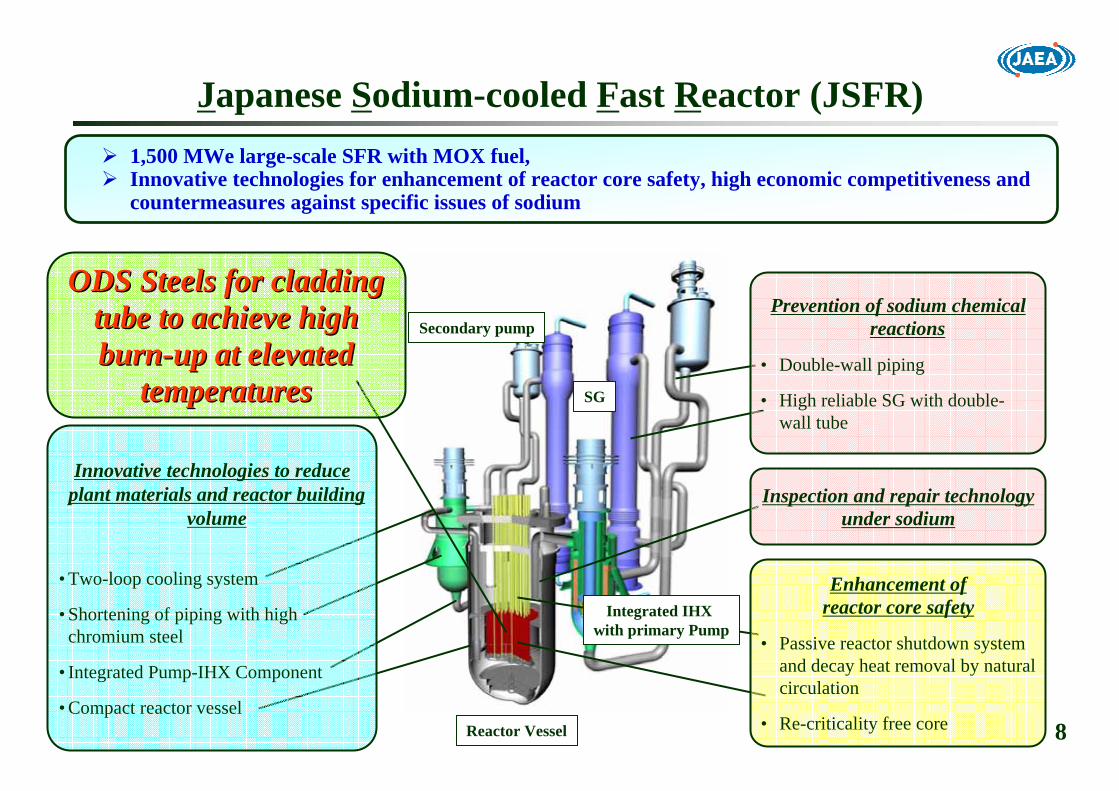
ODS Steels for cladding ODS Steels for cladding tube to achieve high tube to achieve high burnburn--up at elevated up at elevated
temperaturestemperatures
Prevention of sodium chemical reactions
• Double-wall piping
• High reliable SG with double-wall tube
Inspection and repair technology under sodium
Enhancement of reactor core safety
• Passive reactor shutdown system and decay heat removal by natural circulation
• Re-criticality free core
1,500 MWe large-scale SFR with MOX fuel, Innovative technologies for enhancement of reactor core safety, high economic competitiveness and countermeasures against specific issues of sodium
Secondary pump
SG
Integrated IHX with primary Pump
Reactor Vessel
Innovative technologies to reduce plant materials and reactor building
volume
• Two-loop cooling system
• Shortening of piping with high chromium steel
• Integrated Pump-IHX Component
• Compact reactor vessel
Japanese Sodium-cooled Fast Reactor (JSFR)
9
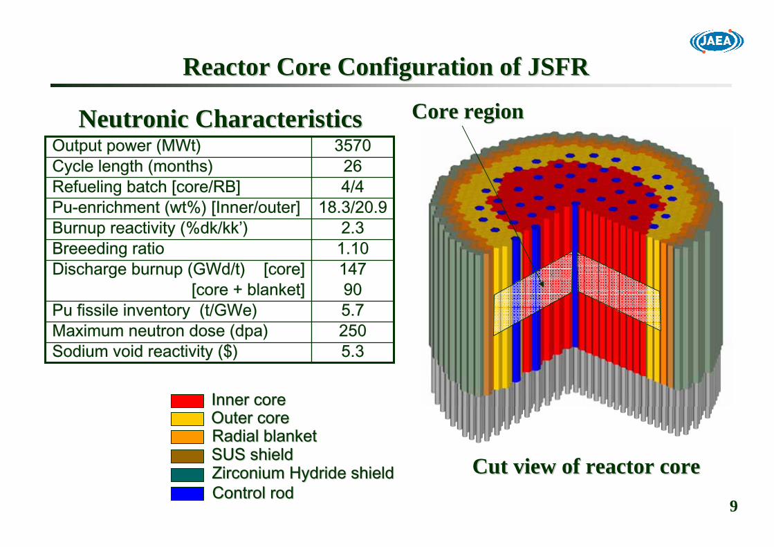
Reactor Core Configuration of JSFRReactor Core Configuration of JSFR
5.3Sodium void reactivity ($)250Maximum neutron dose (dpa)5.7Pu fissile inventory (t/GWe)90[core + blanket]
147Discharge burnup (GWd/t) [core]1.10Breeeding ratio2.3Burnup reactivity (%dk/kk’)
18.3/20.9Pu-enrichment (wt%) [Inner/outer]4/4Refueling batch [core/RB]26Cycle length (months)
3570Output power (MWt)NeutronicNeutronic CharacteristicsCharacteristics Core Core regionregion
Inner core Inner core Outer core Outer core Radial blanketRadial blanketSUS shieldSUS shieldZirconium Hydride shieldZirconium Hydride shieldControl rodControl rod
Cut view of reactor coreCut view of reactor core

10
A DrawingA Drawing of Core Fuel Pin and Subassembly of Core Fuel Pin and Subassembly
An example of design study for 1.5GWe SFR coresAn example of design study for 1.5GWe SFR cores
Fuel PinFuel Pin
SubassemblySubassembly
The original figure can be found in JAEA Research 2006The original figure can be found in JAEA Research 2006--042 (2006), P.042 (2006), P.249249
Molten fuel Molten fuel discharge duct discharge duct at a corner of at a corner of wrapper tubewrapper tube
255 Pin Bundle255 Pin Bundle

11
Chapter 2. Introduction to ODS SteelsChapter 2. Introduction to ODS Steels
Crystallographic Consideration against Irradiation Damages- Body Centered Cubic > Face Centered CubicRequirements and Target Performance for ODS Steels- Reactor and Fuel Cycle- Fuel Pin Mechanical DesignManufacturing Process- Powder Metallurgy- Precision Seamless Tube ProductionBreak Through (Historical Review)- Microstructure Control- Pilger Cold Rolling Process

12
Core Support StructureCore Support Structure((SUS316SUS316))
Cladding TubeCladding Tube((ODS Ferritic SteelODS Ferritic Steel)) Dissimilar WeldedDissimilar Welded
Handling Head(Handling Head(SUS316SUS316))
Wrapper TubeWrapper Tube((PH FMSPH FMS))
Entrance Nozzle(Entrance Nozzle(SUS316SUS316))
Dissimilar WeldedDissimilar Welded
Lower End PlugLower End Plug((ODS SteelODS Steel))
Upper End PlugUpper End Plug((ODS ODS FerriticFerritic SteelSteel))
Spacer WireSpacer Wire((PH FMSPH FMS))
Blanket Fuel Pellets (Blanket Fuel Pellets (UOUO22) )
Core Fuel Pellets (Core Fuel Pellets (MOXMOX))
PRW WeldedPRW Welded
PRW WeldedPRW Welded
Materials for Core Fuel Pin and SubassemblyMaterials for Core Fuel Pin and SubassemblyFuel PinFuel Pin
SubassemblySubassembly
PPrecipitation recipitation HHardened ardened FFerritic erritic MMartensitic artensitic SSteelteel

13
ACO-3(HT-9)-1
0
1
2
3
4
5
6
7
0 40 80 120 160 200 240
HTHT--99PNCPNC--FMSFMSPNC316PNC316
Voi
d Sw
ellin
g (v
olum
e %
)
Neutron Dose (dpa)
FFTFFFTF--CDE(HTCDE(HT--9)9)
MA957MA957
Void Swelling in Various SteelsVoid Swelling in Various SteelsAn observation by TEM for modified SUS316 irradiated in FFTFAn observation by TEM for modified SUS316 irradiated in FFTF
794 K, 105 dpa794 K, 105 dpa
Void swelling will be detrimental in austenitic stainless steelsVoid swelling will be detrimental in austenitic stainless steels over 120 dpa.over 120 dpa.BCC exhibits better swelling resistance than FCC.BCC exhibits better swelling resistance than FCC.→→ FerriticFerritic steels are promising for higher doses than 120 dpa.steels are promising for higher doses than 120 dpa.
Void: ~5vol%Void: ~5vol%
PrecipitatePrecipitate
JNC TN9400 2000JNC TN9400 2000--075 (1999), P.171075 (1999), P.171
HTHT--9: Fe9: Fe--0.2C0.2C--12Cr12Cr--NiMnMoWVNb (Fully Martensitic: Precipitation Hardened), PNCNiMnMoWVNb (Fully Martensitic: Precipitation Hardened), PNC--FMS: FeFMS: Fe--0.12C0.12C--11Cr11Cr--NiMnMoWVNb (Ferritic/Martensitic: Precipitation Hardened)NiMnMoWVNb (Ferritic/Martensitic: Precipitation Hardened)MA957: FeMA957: Fe--14Cr14Cr--0.3Mo0.3Mo--1Ti1Ti--0.25Y0.25Y22OO33 (Fully Ferritic: Oxide Dispersion Strengthened)(Fully Ferritic: Oxide Dispersion Strengthened)
PNC316: FePNC316: Fe--16Cr16Cr--14Ni14Ni--1.7Mn1.7Mn--2.5Mo2.5Mo--0.25P0.25P--0.004B0.004B--0.1Ti0.1Ti--0.1Nb (Austenitic: Precipitation hardened and 20% Cold Work)0.1Nb (Austenitic: Precipitation hardened and 20% Cold Work)
14
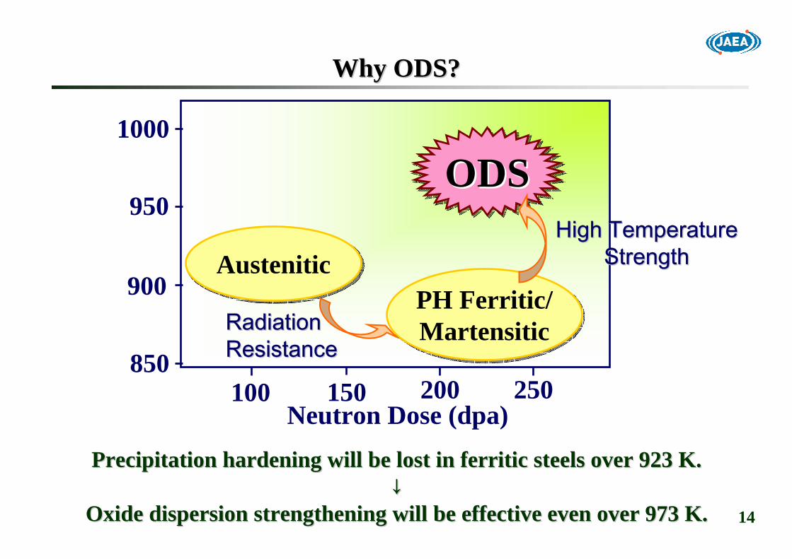
100 150 200 250Neutron Dose (dpa)
Tem
pera
ture
(K)
1000
950
900
850
PH Ferritic/MartensiticPH Ferritic/Martensitic
AusteniticAustenitic
ODSODSODSHigh TemperatureHigh Temperature
StrengthStrength
RadiationRadiationResistanceResistance
Why ODS?Why ODS?
Precipitation hardening will be lost in Precipitation hardening will be lost in ferriticferritic steels over 923 K.steels over 923 K.↓↓
Oxide dispersion strengthening will be effective even over 973 KOxide dispersion strengthening will be effective even over 973 K..

15
Requirements for Fuel Pin Cladding TubesRequirements for Fuel Pin Cladding Tubes
1. Power Plant Performance: Higher Thermal Efficiency1. Power Plant Performance: Higher Thermal Efficiency○○ ReactorReactor Outlet Coolant Temperature: 823 K (550Outlet Coolant Temperature: 823 K (550℃℃))○○ ReactorReactor Inlet Coolant Temperature: 673 K (400Inlet Coolant Temperature: 673 K (400℃℃))
↓↓●● Maximum (Hot Spot) Temperature: 973 K (700Maximum (Hot Spot) Temperature: 973 K (700℃℃))
2. Fuel Cycle Performance: Higher Burnup2. Fuel Cycle Performance: Higher Burnup○○ Discharge Average Burnup of Core Fuel: 150 Discharge Average Burnup of Core Fuel: 150 GWd/tGWd/t○○ Long Term Service: ~9 years (26 monthsLong Term Service: ~9 years (26 months××44 BatchesBatches))
↓↓●● Peak Neutron Dose: ~250 dpaPeak Neutron Dose: ~250 dpa●● Peak Peak BBurnupurnup: ~250 : ~250 GWd/tGWd/t●● Maximum Internal Pressure: ~12 Maximum Internal Pressure: ~12 MPaMPa
16
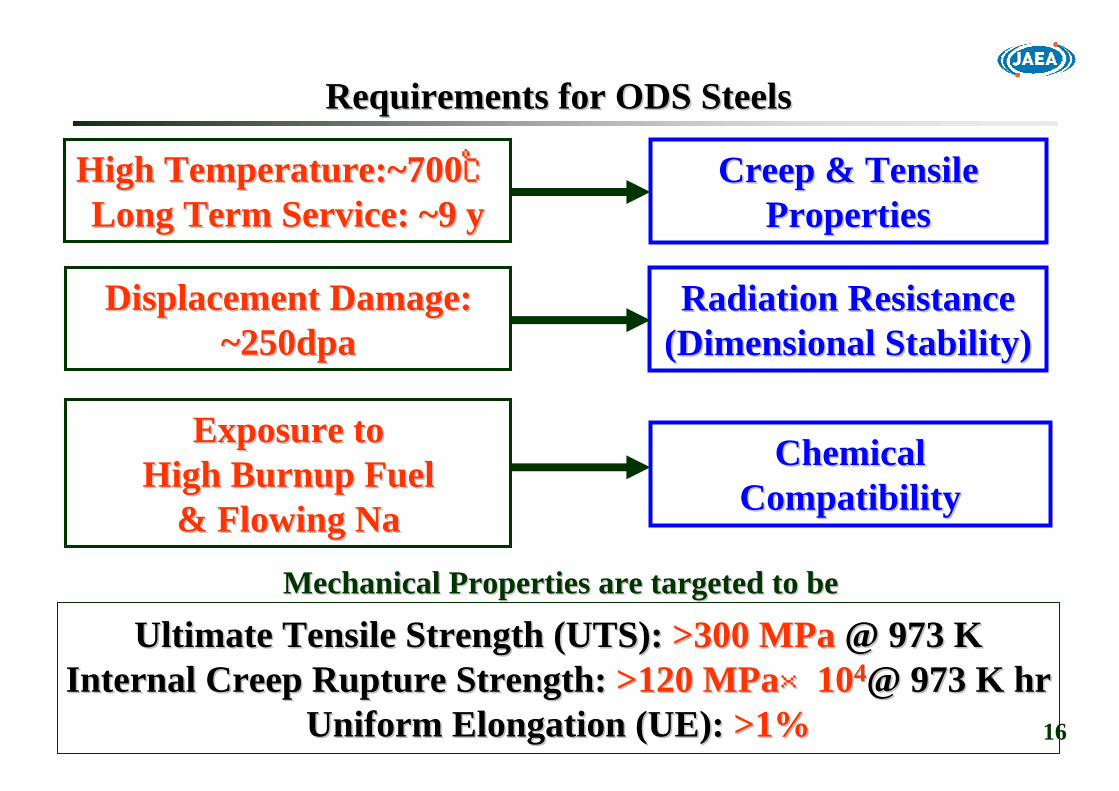
High Temperature:~700High Temperature:~700℃℃Long Term Service: ~9 yLong Term Service: ~9 y
Ultimate Tensile Strength (UTS):Ultimate Tensile Strength (UTS): >300 >300 MPaMPa @ 973 K@ 973 KInternal Creep Rupture Strength:Internal Creep Rupture Strength: >120 MPa>120 MPa××101044@ 973 K hr@ 973 K hr
Uniform Elongation (UE):Uniform Elongation (UE): >1%>1%
Displacement Damage:Displacement Damage:~250dpa~250dpa
Exposure toExposure toHigh Burnup FuelHigh Burnup Fuel
& Flowing Na& Flowing Na
Creep & TensileCreep & TensilePropertiesProperties
Radiation ResistanceRadiation Resistance(Dimensional Stability)(Dimensional Stability)
ChemicalChemicalCompatibility Compatibility
Requirements for ODS SteelsRequirements for ODS Steels
Mechanical Properties are targeted to beMechanical Properties are targeted to be

17
PrePre--alloyed Powderalloyed Powderoror
Elemental PowderElemental Powder
YY22OO3 3 Powder Powder MA powder
Mild steel capsule:Φ67mm
MMechanical echanical AAlloying (MA)lloying (MA)(Ball Milling)(Ball Milling)
Hot Extrusion@ 1,423 K(1,150Hot Extrusion@ 1,423 K(1,150℃℃))
Raw MaterialRaw MaterialPowderPowder
CanningCanningDegassing@673K(400Degassing@673K(400℃℃))
DispersoidDispersoid Size ControlSize Control
Mother Tube Mother Tube
OD18mmOD18mm××IDID12mm12mm××LL180mm:200g180mm:200g
AnnealingAnnealing((ΦΦ25mm)25mm)
DrillingDrilling
Manufacturing Process:1Manufacturing Process:1PPowder owder MMetallurgy (PM) Process for Mother Tubesetallurgy (PM) Process for Mother Tubes
Oxygen pickOxygen pick--upup

18
High Energy Attrition Type Ball Mill for Mechanical AlloyingHigh Energy Attrition Type Ball Mill for Mechanical Alloying
Photographs are supplied by Dr. Fujiwara of Photographs are supplied by Dr. Fujiwara of KobelcoKobelco Research Institute, Inc.Research Institute, Inc.
Balls: 150 kgBalls: 150 kgPowders: 10kg/BatchPowders: 10kg/Batch99.9999%Ar99.9999%Ar220rpm220rpm××48hrs48hrs
10D 10D AttritorAttritor
Mechanically alloyed powders are exposed to air in recovery.Mechanically alloyed powders are exposed to air in recovery.

19
IntermediateIntermediateHeat Treatment Heat Treatment
ColdCold--rolling: rolling: PilgerPilger
Repeat Cladding TubesCladding Tubes
Manufacturing Process:2Manufacturing Process:2Cold Rolling Process from Mother Tubes to Cladding TubesCold Rolling Process from Mother Tubes to Cladding Tubes
Mother Tube Mother Tube
OD8.5mmOD8.5mm××IDID7.57.5mmmm××L1,850mm:180gL1,850mm:180g
Grain Morphology ControlGrain Morphology Control
FinalFinalHeat Treatment Heat Treatment
OD18mmOD18mm××IDID12mm12mm××LL180mm:200g180mm:200g

20
14Cr14Cr--0.3Mo0.3Mo--1Ti1Ti--0.25Y0.25Y22OO33 (MA957)(MA957) 0.12C0.12C--11Cr11Cr--0.5Mo0.5Mo--2W2W--NiMnNbVNiMnNbV--YY22OO33
13Cr13Cr--33WW--0.5Ti0.5Ti--0.350.35YY22OO33 (1DK)(1DK) 0.1C0.1C--11Cr11Cr--33WW--0.5Ti0.5Ti--0.50.5YY22OO33 (1DS)(1DS)
Microstructure Control toMicrostructure Control toImprove Strength Anisotropy Improve Strength Anisotropy
12Cr12Cr--2W2W--0.35Ti0.35Ti--0.230.23YY22OO33 0.13C0.13C--9Cr9Cr--2W2W--0.2Ti0.2Ti--0.350.35YY22OO33Recrystallization in Final Heat TreatmentRecrystallization in Final Heat Treatment4 Passes Cold Rolling4 Passes Cold Rolling
History and Major Break ThroughHistory and Major Break Through
PilgerPilger Cold RollingCold Rolling
RecrystallizationRecrystallization
EBREBR--II Irradiation TestsII Irradiation Tests10 Passes 10 Passes WarmWarm RollingRolling
EBREBR--II Irradiation TestsII Irradiation Tests6 Passes 6 Passes WarmWarm RollingRolling
INCO ProductsINCO Products PNCPNC--FMS+YFMS+Y22OO33
MartensiticMartensitic Transformation in Final Heat TreatmentTransformation in Final Heat Treatment4 Passes Cold Rolling4 Passes Cold Rolling
20052005~~
19871987
19891989
19931993
19919955~~20042004
Alloy Alloy DesigningDesigning
FerriticFerritic MartensiticMartensitic
Two Step AnnealingTwo Step Annealing Cooling Rate ControlCooling Rate Control
Alpha to GammaAlpha to GammaTransformationTransformation
21
Two Candidates of ODS Steels for Further R&D in Two Candidates of ODS Steels for Further R&D in FaCTFaCT
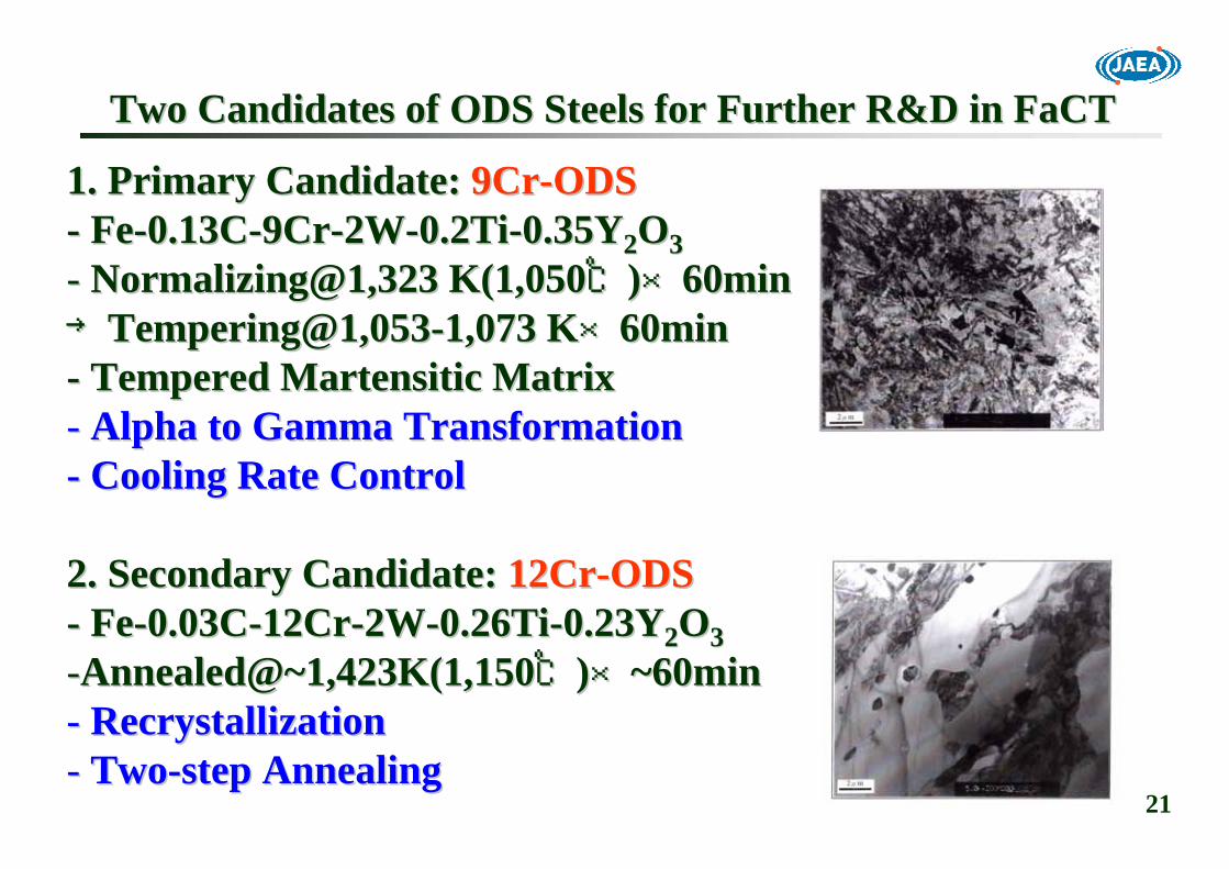
1. Primary Candidate: 1. Primary Candidate: 9Cr9Cr--ODSODS-- FeFe--0.13C0.13C--9Cr9Cr--2W2W--0.2Ti0.2Ti--0.35Y0.35Y22OO33-- Normalizing@1,323 K(1,050Normalizing@1,323 K(1,050℃℃))××6060minmin→→TemperingTempering@1,053@1,053--1,073 K1,073 K××6060minmin-- Tempered Tempered MartensiticMartensitic Matrix Matrix -- Alpha to Gamma TransformationAlpha to Gamma Transformation-- Cooling Rate ControlCooling Rate Control
2. Secondary Candidate: 2. Secondary Candidate: 12Cr12Cr--ODSODS-- FeFe--0.03C0.03C--12Cr12Cr--2W2W--0.26Ti0.26Ti--0.23Y0.23Y22OO33--Annealed@~1,423K(1,150Annealed@~1,423K(1,150℃℃))××~~6060minmin-- RecrystallizationRecrystallization-- TwoTwo--step Annealingstep Annealing

22
Chapter 3. Alloy DesignChapter 3. Alloy Design
Selecting alloying elementsSelecting alloying elements-- Understanding strengthening mechanismsUnderstanding strengthening mechanisms-- Predicting phase diagramsPredicting phase diagrams
Optimizing chemical compositionsOptimizing chemical compositions-- Specimen preparationsSpecimen preparations-- Tensile and creep testsTensile and creep tests-- TradeTrade--off between strength, toughness and manufacturingoff between strength, toughness and manufacturing
Unanticipated phenomena and empirical approachUnanticipated phenomena and empirical approach--δδ phase formation (not equilibrium phase) in 9Crphase formation (not equilibrium phase) in 9Cr--ODSODS-- RecrystallizationRecrystallization (highly empirical) in 12Cr(highly empirical) in 12Cr--ODSODS

23
Alloying Concepts and SpecificationsAlloying Concepts and Specifications
DDDDDDSSMMMMMechanismMechanism
0.070.070.230.230.260.262.02.012.012.00.030.0312Cr12Cr--ODSODS0.070.070.350.350.200.202.02.09.09.00.130.139Cr9Cr--ODSODS
Ex.OEx.OYY22OO33TiTiWWCrCrCCElementElement
D: Dispersion Strengthening, S: Solution Hardening,D: Dispersion Strengthening, S: Solution Hardening,P: Precipitation Hardening, M: Phase ControlP: Precipitation Hardening, M: Phase Control
0.500.50SS
MoMo
0.400.40MMNiNi
0.600.60MM
MnMnPPPPPPSSMMM/PM/PMechanismMechanism
0.050.050.050.050.200.202.02.011.011.00.120.12PNCPNC--FMSFMS
NNNbNbVVWWCrCrCCElementElement
Impurity: Impurity: Mn,Ni,N,Ar,Si,P,SMn,Ni,N,Ar,Si,P,S
in wt%in wt%
Martensitic/FerriticMartensitic/Ferritic & Precipitation Hardened: PNC& Precipitation Hardened: PNC--FMSFMS
Normalizing@1,373 K(1,100Normalizing@1,373 K(1,100℃℃))××10min10min→→Tempering@1,053 K(780Tempering@1,053 K(780℃℃))××60min60min
Content Yttrium17848Content nTolalOxygeEx.O −=
Oxygen picked up during PM process is called as Excess Oxygen (Oxygen picked up during PM process is called as Excess Oxygen (Ex.OEx.O),),but it is the most important alloying element !!but it is the most important alloying element !!

24
Cr Contents: Phase Control and Chemical CompatibilityCr Contents: Phase Control and Chemical Compatibility
9Cr9Cr--ODSODS Steel: Steel: Martensitic- Large capacity for trapping radiation-induced point defects.→ Lower irradiation embrittlement
-Alpha to Gamma Transformation→ Anisotropy-free mechanical properties
- More stable oxide films on surfaceFuel-cladding chemical interaction (FCCI)Nitric acid dissolution
→ Better corrosion resistance with minimal embrittlement
12Cr12Cr--ODS: Fully ODS: Fully FerriticFerritic
FeFe--0.13C0.13C--2W2W--0.2Ti0.2Ti--xCr in mass%xCr in mass%
25
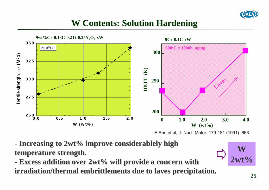
W Contents: Solution HardeningW Contents: Solution Hardening
25 0
27 5
30 0
32 5
35 0
0 .0 0 .5 1 .0 1 .5 2 .0
7 0 0 o C
W (w t% )
9wt%Cr-0.13C-0.2Ti-0.35Y2O3-xW
-- Increasing to 2wt% improve Increasing to 2wt% improve considerablelyconsiderablely highhightemperature strength.temperature strength.-- Excess addition over 2wt% will provide a concern withExcess addition over 2wt% will provide a concern withirradiation/thermal irradiation/thermal embrittlementsembrittlements due to laves precipitation.due to laves precipitation.
F.AbeF.Abe et al, J. et al, J. NuclNucl. Mater. 179. Mater. 179--181 (1991) 663.181 (1991) 663.
9Cr-0.1C-xW
W (wt%)0 1.0 2.0 3.0 4.0
300
250
200
DB
TT
(K
)
600oC x 1000h aging
Laves
W2wt%

26
Oxide Oxide DDispersion Strengthening Theoryispersion Strengthening Theory
Threshold stress to Dislocation Motion
⎥⎦
⎤⎢⎣
⎡+⎟⎟
⎠
⎞⎜⎜⎝
⎛= 0
0
~ln
2B
rDGbAVOr λπ
τ
6.0),47(cos1
sin10
2
=°=−
+ Bϕϕν
ϕν: Screw dislocation
: Edge dislocation
sdD11
~1
+=•λ
r0 : dislocation core cut-off radius
ds
ϕλ
sd: Average obstacle spacing
: Average obstacle diameter
7.0),19(cossin1
1 02 =°=⎟
⎠⎞
⎜⎝⎛
−− Bϕϕϕ
νν=• VA
Smaller obstacles (dispersoids) interspacing provides - higher threshold stress to dislocation motion and
- higher strength at elevated temperature.↓
Finer dispersoids and higher number density is desirable.Srolovitz mechanism: Incoherent obstacle

27
Refinement of Refinement of DispersoidDispersoid Size by Minor Alloying ElementsSize by Minor Alloying Elements
DispersoidDispersoid sizes depend on minor alloying sizes depend on minor alloying element(selement(s) and amount of ) and amount of Ex.OEx.O. . ↓↓
TiTitanium addition with tanium addition with Ex.OEx.O is very effective to enhance ODS effect.is very effective to enhance ODS effect.
○○DispersoidsDispersoids will precipitatewill precipitateduring hotduring hot--consolidation.consolidation.
↓↓Nucleation and Growth KineticsNucleation and Growth Kinetics
in Coin Co--PrecipitationPrecipitation
ZrZr
VV
NbNb
TiTi
NoneNone
Particle Size (nm)Particle Size (nm)
Rel
ativ
e Fr
eque
ncy
(%)
Rel
ativ
e Fr
eque
ncy
(%)
Detailed mechanism is not clearDetailed mechanism is not clear
○This refinement needs Ex.O.↓
Y2O3 + 2Ti + 4Ex.O = Y2Ti2O7

28
5060708090
100
200
300
400500
101 102 103 104 105
Time to rupture (h)
0.08wt%Ex.O
700 oC
9wt%Cr-0.13C-0.2Ti-2W
0.46wt%Ti
0.2wt%Ti
0.15wt%Ex.O 0.03wt%Ex.O0.08wt%Ex.O
0.35wt%Ti0.11wt%Ex.O
YY22OO33, Ti & Excess Oxygen (, Ti & Excess Oxygen (Ex.OEx.O) Contents) Contents
50
100
150
200
0 0.05 0.1 0.15 0.2Excess oxygen, Ex.O (wt%)
700oC
9Cr-0.13C-2W-0.2Ti-0.35Y2O3-xEx.O
○Increasing Y2O3 and Ti contents improve mechanical strength,while it leads to considerable degradation of tube manufacturability.○Too much Ex.O degrades mechanical strength.
=> 0.2Ti-0.35Y2O3-0.08Ex.O
29
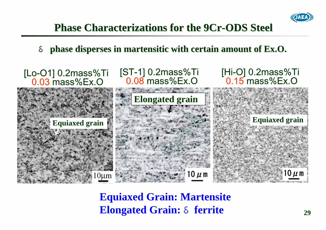
Phase Characterizations for the 9CrPhase Characterizations for the 9Cr--ODS SteelODS Steel
[Hi-O] 0.2mass%Ti 0.15 mass%Ex.O
Elongated grain
[ST-1] 0.2mass%Ti 0.08 mass%Ex.O
Equiaxed grain Equiaxed grain
[Lo-O1] 0.2mass%Ti 0.03 mass%Ex.O
δδ phase disperses in phase disperses in martensiticmartensitic with certain amount of with certain amount of Ex.OEx.O..
Equiaxed Grain: MartensiteElongated Grain: δferrite

30
Phase diagram prediction does not indicate δ ferrite formation.↓
Isδ ferrite non-equibrium phase at 1150oC ?
Unanticipated Phenomena in the 9CrUnanticipated Phenomena in the 9Cr--ODS Steel ODS Steel

31
As mechanically alloyedW W
11501150ooC C annealeannealed and quenchedd and quenched
FineFine--grained structure produced by severe grained structure produced by severe plastic deformationplastic deformation
Ferrite(α)/austenite(γ) duplex
ferrite
Martensite
Ultra-fine ferrite (a)
δ ferrite FormationNon-equibrium phase at 1150oC.
Mechanically-alloyedpowder
δδ Ferrite Formation during Hot ConsolidationFerrite Formation during Hot Consolidation
32
W
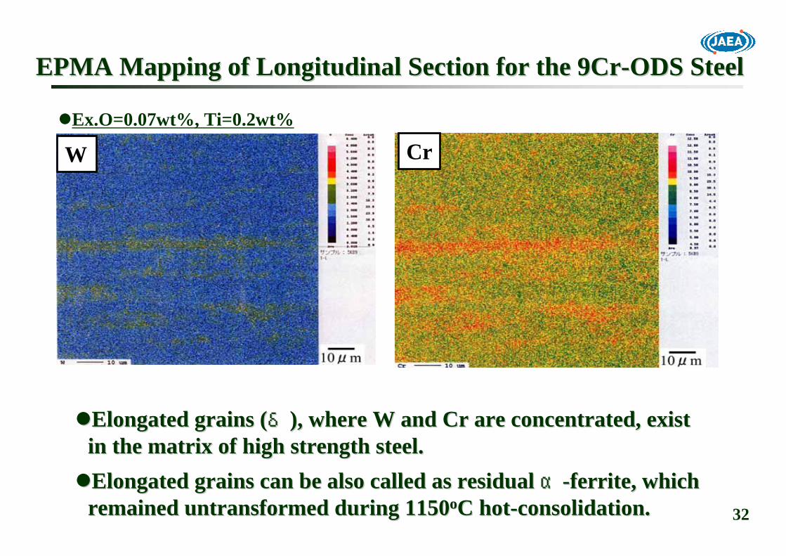
EPMA Mapping of Longitudinal Section for the 9CrEPMA Mapping of Longitudinal Section for the 9Cr--ODS Steel ODS Steel
Cr
Elongated grains (Elongated grains (δδ), where W and Cr are concentrated, exist ), where W and Cr are concentrated, exist in the matrix of high strength steel. in the matrix of high strength steel. Elongated grains can be also called as residual Elongated grains can be also called as residual αα--ferrite, which ferrite, which remained untransformed during 1150remained untransformed during 1150ooC hotC hot--consolidation.consolidation.
Ex.O=0.07wt%, Ti=0.2wt%
33
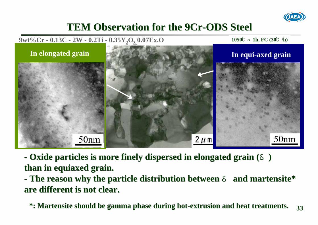
TEM Observation for the 9CrTEM Observation for the 9Cr--ODS SteelODS Steel
-- Oxide particles is more finely dispersed in elongated grain (Oxide particles is more finely dispersed in elongated grain (δδ))than in equiaxed grain.than in equiaxed grain.-- The reason why the particle distribution between The reason why the particle distribution between δδ and and martensitemartensite* * are different is not clear. are different is not clear.
In elongated grain In equi-axed grain
9wt%Cr - 0.13C - 2W - 0.2Ti - 0.35Y2O3-0.07Ex.O 1050℃×1h, FC (30℃/h)
**: : MartensiteMartensite should be gamma phase during hotshould be gamma phase during hot--extrusion and heat treatments.extrusion and heat treatments.

34
10
100
1000
101 102 103 104 105
MartensiteMartensite & & δδ
Fine
Time to Rupture (hr)Time to Rupture (hr)
Stre
ss (
Stre
ss ( M
PaM
Pa))
Fully Fully MartesiticMartesitic
CoarseCoarse
TargetTarget
Composite Composite Nature of the 9CrNature of the 9Cr--ODS SteelODS Steel
-- Certain amount of Certain amount of δδ ferrite is essential to attain the target.ferrite is essential to attain the target.-- The 9CrThe 9Cr--ODS steel is reODS steel is re--enforced by enforced by δδ ferrite.ferrite.

35
Too much Ex.O addition produces excessive, since Y-Ti-O particles are detrimental to recrystallization control.
=> 0.3Ti=> 0.3Ti--0.23Y0.23Y22OO33
RecrystallizationRecrystallization Threshold in the 12CrThreshold in the 12Cr--ODS Steel ODS Steel
=> 0.07Ex.O=> 0.07Ex.O
YY22OO33 (mass%)(mass%)
Exce
ssiv
e O
xyge
n (m
ass%
)Ex
cess
ive
Oxy
gen
(mas
s%)

36
Ex.OEx.O
Tube ManufacturabilityTube Manufacturability((MicroMicrostructure Controllability)structure Controllability)YY22OO33
HighHigh--temperature Strength temperature Strength ((ODS)(DispersoidODS)(Dispersoid Morphology)Morphology)
NonNon--equilibrium Phase Generationequilibrium Phase Generation
TiTi
Irradiation/Thermal Irradiation/Thermal EmbrittlementEmbrittlement(Laves, d(Laves, d--ferrite in ferrite in MartensiteMartensite))
HighHigh--temperature Strengthtemperature Strength(Solution Hardening)(Solution Hardening)(Finer Precipitation of M(Finer Precipitation of M2323CC66))
WW
Irradiation/Thermal Irradiation/Thermal EmbrittlementEmbrittlement(Cr(Cr--rich phase: rich phase: αα’’))
δδ--ferrite in ferrite in martensitemartensite
Corrosion ResistanceCorrosion Resistance( ( >> 12 mass%)12 mass%)CrCr
DegradationDegradationImprovementImprovement
Summary of Alloy EffectsSummary of Alloy Effects
Excess Oxygen (Excess Oxygen (Ex.OEx.O) is the most important alloying element,) is the most important alloying element,but its effect is not well clarified.but its effect is not well clarified.

37
Concepts of Alloy Design Concepts of Alloy Design
9Cr9Cr--ODS steel: 9CrODS steel: 9Cr--0.13C0.13C--2W2W--0.2Ti0.2Ti--0.35Y0.35Y22OO33--0.07Ex.O0.07Ex.O-- C,CrC,Cr:: RadiationRadiation--resistant resistant martensiticmartensitic matrixmatrix
(microstructure control)(microstructure control)-- WW: : Solution hardening, little laves precipitationSolution hardening, little laves precipitation-- Ti, YTi, Y22OO33, , Ex.OEx.O: : Oxide dispersion strengtheningOxide dispersion strengthening
δδferriteferrite formationformation
12Cr12Cr--ODS steel: 12CrODS steel: 12Cr--0.13C0.13C--2W2W--0.26Ti0.26Ti--0.23Y0.23Y22OO33--0.07Ex.O0.07Ex.O-- CrCr: : Corrosion resistant fully Corrosion resistant fully ferriticferritic-- WW: : Solution hardening, little laves precipitationSolution hardening, little laves precipitation-- Ti, YTi, Y22OO33, , Ex.OEx.O: : Oxide dispersion strengtheningOxide dispersion strengthening
RecrystallizationRecrystallization

38
Powder Metallurgy ProcessPowder Metallurgy Process-- DispersoidDispersoid Size/Distribution ControlSize/Distribution Control-- Uniform Solid Solution by Mechanical AlloyingUniform Solid Solution by Mechanical Alloying-- Precipitation of Precipitation of NanoNano Particles during Hot ConsolidationParticles during Hot Consolidation
Precision Seamless Tube Production ProcessPrecision Seamless Tube Production Process-- Grain Morphology ControlGrain Morphology Control-- PilgerPilger Cold Rolling (Cold Rolling (ZircalloyZircalloy Tubing)Tubing)-- Intermediate and Final Heat TreatmentsIntermediate and Final Heat Treatments-- Temperature HistoryTemperature History
Chapter 4. Microstructure ControlChapter 4. Microstructure Control

39
High Energy Attrition Type Ball Mill for Mechanical AlloyingHigh Energy Attrition Type Ball Mill for Mechanical Alloying
WW
CrCr
EPMA Mapping forEPMA Mapping forAsAs--mechanically Alloyed Powdermechanically Alloyed Powder
9Cr9Cr--0.2Ti0.2Ti--0.08Ex.O0.08Ex.O
BallBall--toto--Ball CollisionBall Collision
1.Consolidation1.Consolidation
2.Fragmentation2.Fragmentation
3. Severe Plastic Deformation3. Severe Plastic Deformation
InstantaneousInstantaneousDeformationDeformation
++LocalizedLocalizedHeating!!Heating!!
Uniform Solid SolutionUniform Solid Solution

40
Precipitation of Nanometer Size Oxide Particles
Y + Ti + O → Y2O3・yTiOx,
Ex.O = x・y
The original figure can be found in "T.Okuda and M. Fujiwara,J. Materials Science Letters, 14(1995)1600".
13001300℃℃ x 1hrx 1hr
12001200℃℃ x 1hrx 1hr
11001100℃℃ x 1hrx 1hr
10001000℃℃ x 1hrx 1hr
900900℃℃ x 1hrx 1hr
9Cr-0.13C-2W-0.2Ti-0.35Y2O3
Oxide particleOxide particle
Yttrium oxide dissociates and dissolvesYttrium oxide dissociates and dissolvesinto matrix during mechanical alloyinginto matrix during mechanical alloyingdue to high energy ball milling.due to high energy ball milling.
Titanium and yttrium complex oxideTitanium and yttrium complex oxidenanonano--particles precipitateparticles precipitateduring hot consolidation process.during hot consolidation process.
AsAs--MAedMAed
Mechanical Alloying and Hot ConsolidationMechanical Alloying and Hot Consolidation→→ DispersoidDispersoid Size ControlSize Control
41
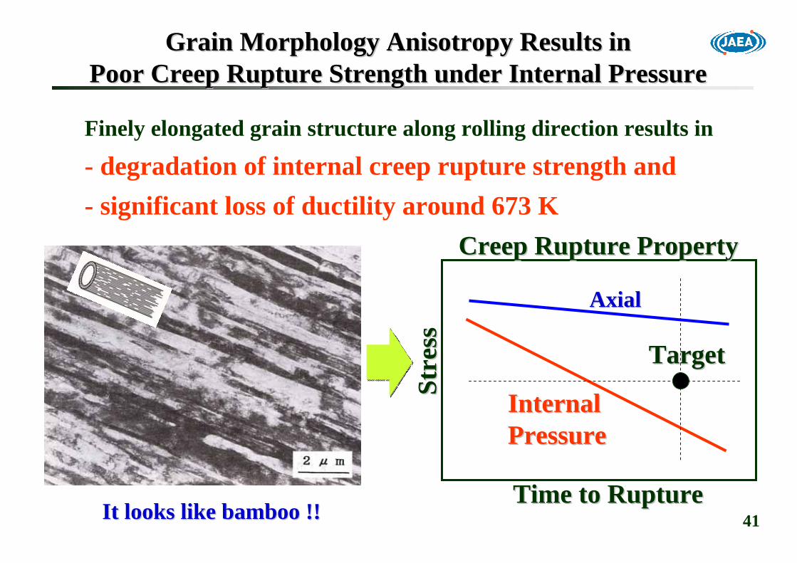
Grain Morphology Anisotropy Results inGrain Morphology Anisotropy Results inPoor Creep Rupture Strength under Internal PressurePoor Creep Rupture Strength under Internal Pressure
Finely elongated grain structure along rolling direction results in
- degradation of internal creep rupture strength and- significant loss of ductility around 673 K
AxialAxial
InternalInternalPressurePressure
Time to RuptureTime to Rupture
Stre
ssSt
ress
It looks like bamboo !!It looks like bamboo !!
Creep Rupture PropertyCreep Rupture Property
TargetTarget
42
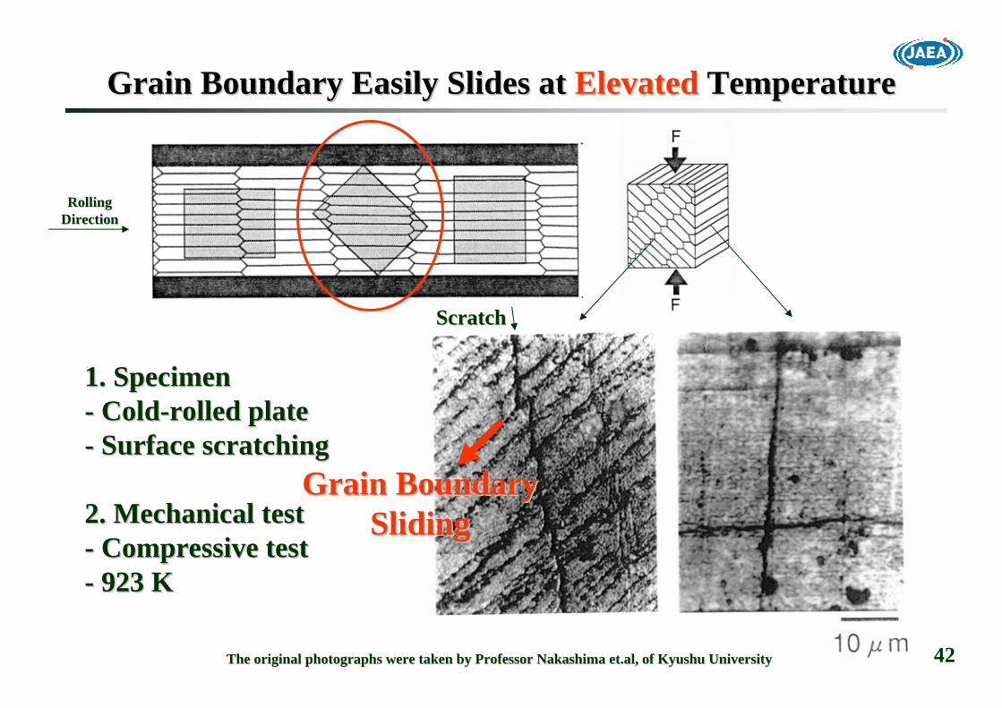
Grain Boundary Easily Slides at Grain Boundary Easily Slides at ElevatedElevated TemperatureTemperature
ScratchScratch
1. Specimen1. Specimen-- ColdCold--rolled platerolled plate-- Surface scratchingSurface scratching
2. Mechanical test2. Mechanical test-- Compressive testCompressive test-- 923 K923 K
The original photographs were taken by Professor Nakashima The original photographs were taken by Professor Nakashima et.alet.al, of Kyushu University, of Kyushu University
Grain BoundaryGrain BoundarySlidingSliding
RollingRollingDirectionDirection
43
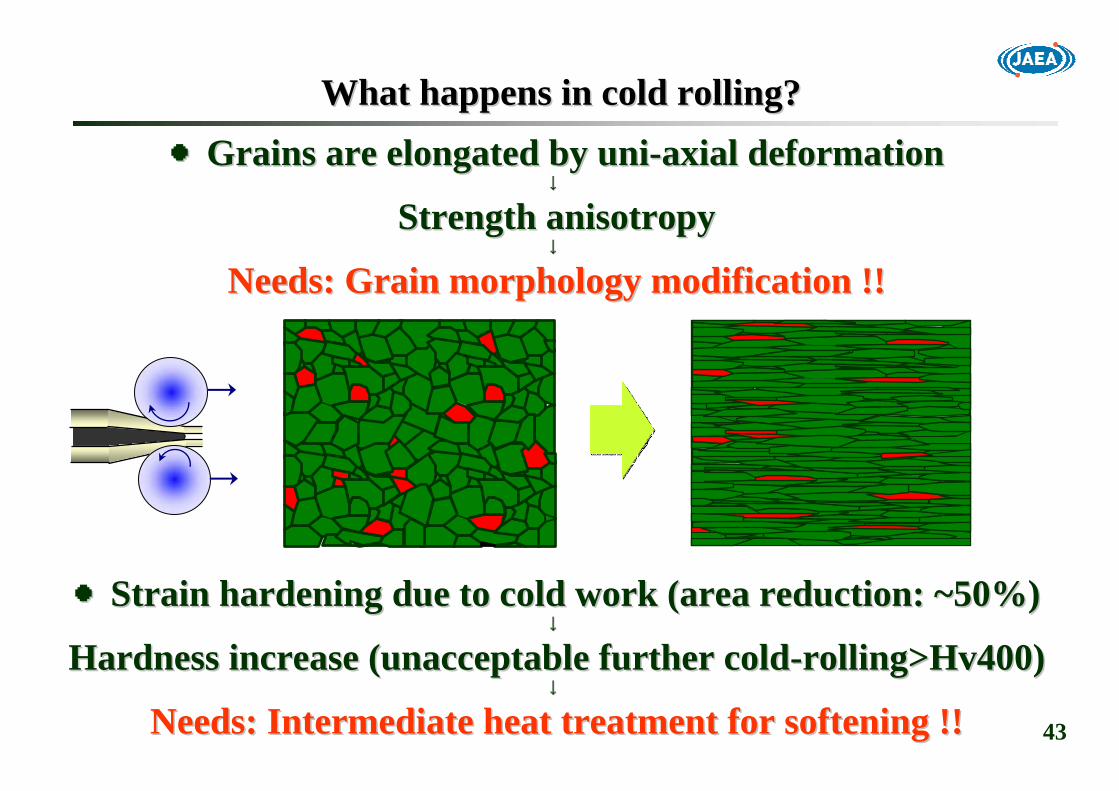
What happens in cold rolling?What happens in cold rolling?
●●Grains are elongated by Grains are elongated by uniuni--axial deformationaxial deformation↓↓
StrengthStrength anisotropyanisotropy↓↓
Needs: Needs: Grain Grain morphology modification !!morphology modification !!
●●Strain hardening due to cold work (area reduction: ~50%)Strain hardening due to cold work (area reduction: ~50%)↓↓
Hardness increase (unacceptable further coldHardness increase (unacceptable further cold--rolling>Hv400)rolling>Hv400)↓↓
Needs: Needs: IntermediateIntermediate heat treatment for softening !!heat treatment for softening !!
44
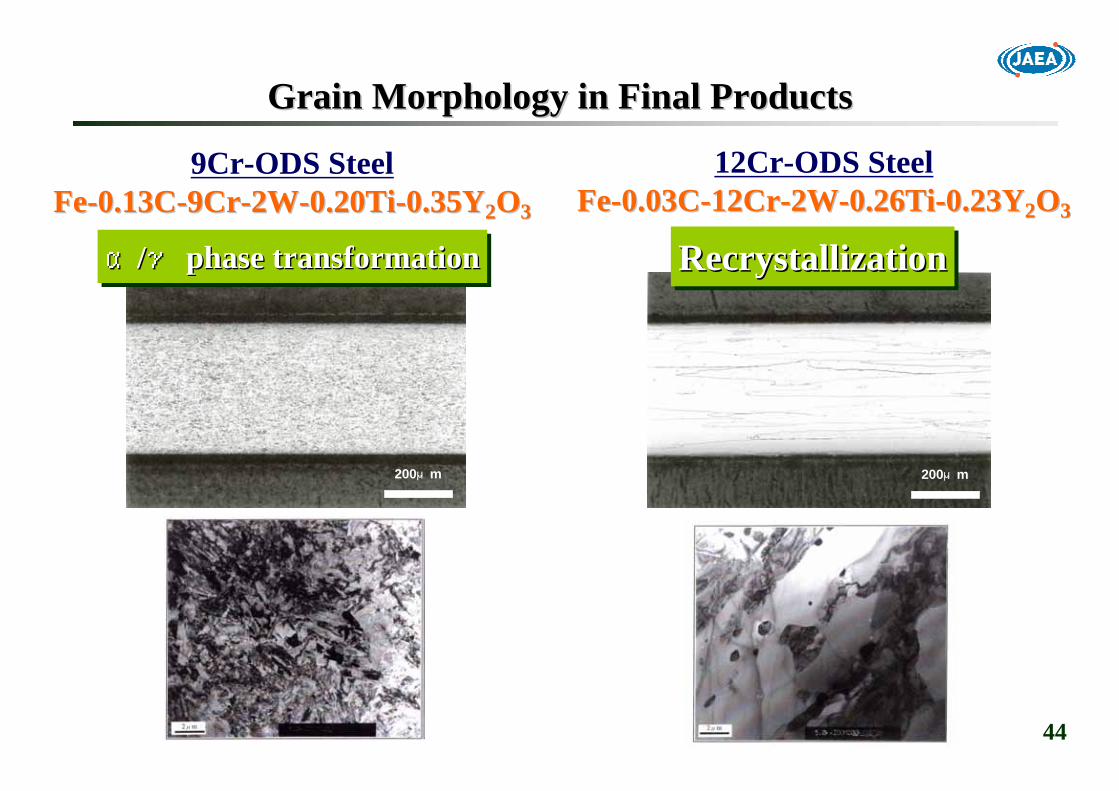
9Cr-ODS SteelFeFe--0.13C0.13C--9Cr9Cr--2W2W--0.20Ti0.20Ti--0.35Y0.35Y22OO33
12Cr-ODS SteelFeFe--0.03C0.03C--12Cr12Cr--2W2W--0.26Ti0.26Ti--0.23Y0.23Y22OO33
200μm 200μm
α/γ phase transformationαα//γγ phase transformationphase transformation RecrystallizationRecrystallizationRecrystallization
Grain Morphology in Final ProductsGrain Morphology in Final Products
45
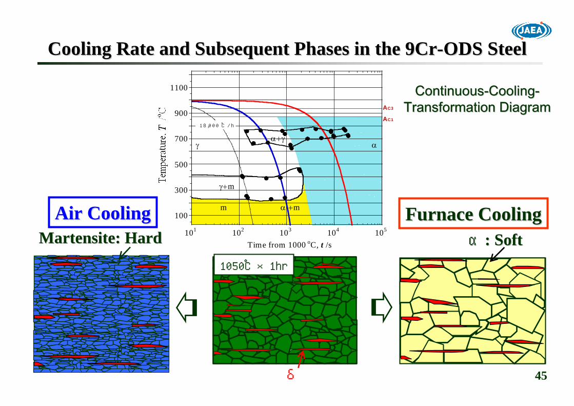
Cooling Rate and Subsequent Phases in the 9CrCooling Rate and Subsequent Phases in the 9Cr--ODS SteelODS Steel
100
300
500
700
900
1100
101 102 103 104 105
Time from 1000 oC, t /s
γα+γ
γ+m
m α +m
α
18,000 ℃/hAC1
AC3
Furnace CoolingFurnace Cooling
1050℃×1hr
αα: Soft: Soft
δ
MartensiteMartensite: Hard: HardAir CoolingAir Cooling
ContinuousContinuous--CoolingCooling--Transformation DiagramTransformation Diagram

46
Simultaneous Control of Softening/Hardening Simultaneous Control of Softening/Hardening Intention and Grain Morphology for the 9CrIntention and Grain Morphology for the 9Cr--ODS SteelODS Steel
Cold-rolling (Rd≒50%)
300
350
400
450
Har
dnes
s (H
v)
Mothertube
1st 2nd 3rd
Final HeatFinal Heat--treatmenttreatment1050oC×60 min×AC+800oC×60 min×AC
1st 2nd 3rd 4th
Intermediate HeatIntermediate Heat--treatmenttreatment1050oC×30 min×FC (150 oC/h)
As cold-rolled After heat treated
δferrite
Tempered martensite

47
●●Control of Control of recrystalizationrecrystalization is more difficult than that of alpha to is more difficult than that of alpha to gamma transformation.gamma transformation.●●Recrystallized grains should be produced at the final heatRecrystallized grains should be produced at the final heat--treatment treatment to improve strength and ductility against internal pressure.to improve strength and ductility against internal pressure.●●RecrystaRecrystalllizationlization phenomena depends empirically on texture phenomena depends empirically on texture evolution {111}<110>. evolution {111}<110>.
1CR
2CR 3CR4CR
IHT-1
IHT-2IHT-3
Mother Tube
Technical Problems of the 12CrTechnical Problems of the 12Cr--ODS SteelODS Steel
Reduction:40-50%Increasing hardness
Increasing hardness

48
1,373K30min
1,423K120min
1,423K30min
100μm
AnnealedAnnealedNot Not RecrystallizedRecrystallizedRecrystallizedRecrystallized
1,373K30min 1,323K
120min
1,423K30min
AnnealedAnnealed
1,373K30min
1,423K30min
AnnealedAnnealed
100μm
100μm
AnnealedAnnealed
1,323K10min
AnnealedAnnealed1,323K120min
AnnealedAnnealed
Partially Partially RecrystallizedRecrystallized
Fully Fully RecrystallizedRecrystallized
1-CRLow Stored Energy
Moderate Stored Energy=> Uniform Nucleation
2CR 3CR 4CR
Excess Stored Energy=> Inhomogeneous Nucleation
Effect of Stored Energy for Nucleation in the12CrEffect of Stored Energy for Nucleation in the12Cr--ODS SteelODS Steel12Cr-2W-0.3Ti-0.23Y2O3
11--IHTIHT 22--IHTIHT FHTFHT
11--IHTIHT 22--IHTIHT FHTFHT
11--IHTIHT 22--IHTIHT FHTFHT33--IHTIHT
{111}{111}<110><110>

49
Specimen for TwoSpecimen for Two--Step Heat Treatment TestStep Heat Treatment Test
Preparation for 3rd Cold-Rolled Specimens without Recrystallizaation
Mother Tubeφ18.0mm×t3.0mm
After First IHT@1,348K×30min
After Second IHT@1,398K×30min
First CR (1CR)φ14.0mm×t1.82mm50.7% Rd
CR: Cold RollingRd: ReductionIHT: Intermediate Heat treatment
Second CR (2CR) φ11.0mm×t1.10mm50.9% Rd
Third CR (3CR)φ8.67mm×t0.66mm51.5% Rd
150
200
250
300
350
400
450
500
550
Har
dnes
s (H
v)
Two Step Heat Treatment Test

50● The aim of this test is to establish a heat treatment technique to consistenstly
and reiliably produce the recovered structure (<400Hv) without recrystallization.
One Step Heat TreatmentOne Step Heat Treatment
ACAC
1,5231,523KK(1,250(1,250℃℃))××3030minmin
ACAC
1,5231,523KK(1,250(1,250℃℃))××3030minmin
1,3231,323KK(1,050(1,050℃℃))××3030minmin
Two Step Heat TreatmentTwo Step Heat Treatment
Hv~450Hv~450HvHv
~320~320 Hv~450Hv~450HvHv
~380~380
100μm
RecrystallizedRecrystallized100μm
Not Not RecrystallizedRecrystallized
RollingRollingDirectionDirection
OneOne-- and Twoand Two--Step Heat Treatment TestsStep Heat Treatment Testsafter 3rd Cold Rollingafter 3rd Cold Rolling

51
Basic idea of Two Step Basic idea of Two Step HHeat Treatments foreat Treatments forRecrystallizationRecrystallization ControlControl
Cold Work Level (%)
Tem
pera
ture
(o C
)
● The second step H/T at higher temperature can sufficiently soften cladding tube without recrystallization.
● The first step H/T provides the recovery of strain energy which elevates the threshold temperature for recrystallization.
Rec
ryst
alliz
atio
n T
empe
ratu
re(
Rec
ryst
alliz
atio
n T
empe
ratu
re( ℃℃
))
RR11RR22
T0
T2
T0'
T1
RecrystallizationRecrystallization
Two-Step H/Tat T2
No RecrystallizationNo RecrystallizationOne-Step H/T
at T2
Two-Step H/Tat T1
Threshold Temp.for Recrystallization

52
Grain Morphology ControlGrain Morphology Control
9Cr-ODS Steel: Alpha to Gamma Transformation.
12Cr-ODS: Recrystallization after Two-step Annealing
-- Intermediated heat treatment with slower cooling rate Intermediated heat treatment with slower cooling rate softens and allows to cold roll without crackingsoftens and allows to cold roll without cracking..-- Final heat treatment (normalizing + tempering) produces Final heat treatment (normalizing + tempering) produces equiaxedequiaxed tempered tempered martensitemartensite (with (with δδphasephase ) with little ) with little strength anisotropy. strength anisotropy.
-- Once recrystallization took place in the course of coldOnce recrystallization took place in the course of cold--rolling process, rolling process, recrystallizedrecrystallized microstructuremicrostructure can not be can not be obtained at final heat treatment. obtained at final heat treatment. -- ““TwoTwo--step annealingstep annealing”” is useful to soften the coldis useful to soften the cold--rolled rolled tubes without premature tubes without premature recrystallizationrecrystallization in intermediate in intermediate heat treatments.heat treatments.
53
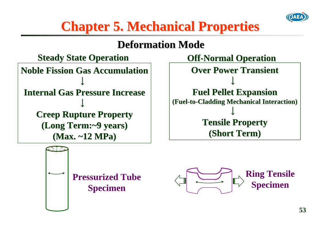
Noble Fission Gas AccumulationNoble Fission Gas Accumulation↓↓
Internal Gas Pressure IncreaseInternal Gas Pressure Increase↓↓
Creep Creep Rupture Rupture PropertyProperty(Long Term:~9 years)(Long Term:~9 years)
(Max. ~12 (Max. ~12 MPaMPa))
Ring TensileSpecimen
Over Power TransientOver Power Transient↓↓
Fuel Pellet ExpansionFuel Pellet Expansion(Fuel(Fuel--toto--Cladding Mechanical Interaction)Cladding Mechanical Interaction)
↓↓Tensile PropertyTensile Property
(Short Term)(Short Term)
Pressurized TubeSpecimen
Steady State OperationSteady State Operation OffOff--Normal OperationNormal OperationDeformation ModeDeformation Mode
Chapter 5. Mechanical PropertiesChapter 5. Mechanical Properties

54
Material Strength Standard for Fuel Pin Mechanical DesignMaterial Strength Standard for Fuel Pin Mechanical Design
1. Manufacturing process, 2. Chemical composition,1. Manufacturing process, 2. Chemical composition,3. Final heat treatments3. Final heat treatmentsSpecificationsSpecifications
1. Young modulus, 2. Poisson ratio, 3. Thermal expansion, 4. The1. Young modulus, 2. Poisson ratio, 3. Thermal expansion, 4. Thermalrmalconductivity, 5. Heat capacity, 6. Density, 7. Transformation poconductivity, 5. Heat capacity, 6. Density, 7. Transformation pointint
Environmental effectsEnvironmental effects
StressStress--strain strain correlationcorrelation
Physical propertiesPhysical properties4. Void swelling4. Void swelling3. Fuel3. Fuel--toto--cladding chemical interaction: FCCIcladding chemical interaction: FCCI2. Sodium corrosion2. Sodium corrosion1. Environmental effect adjusting factor1. Environmental effect adjusting factor3. Irradiation creep strain3. Irradiation creep strain2. Thermal creep strain2. Thermal creep strain1. Short1. Short--term stressterm stress--strain strain 3. High3. High--cycle fatigue propertycycle fatigue property2. Creep rupture strength2. Creep rupture strength1. Short1. Short--term strength (term strength (σσyy, , σσuu))
Weld material strengthWeld material strength
4. Transient burst rupture strength4. Transient burst rupture strength3. Fatigue strength3. Fatigue strength22.. Creep rupture strength (Creep rupture strength (σσRR))1. Short1. Short--term tensile strength (term tensile strength (σσyy, , σσuu))
Material strengthMaterial strengthJNC TN9400 2005-015 (2005)

55
0
500
1000
1500
200 400 600 800 1000 1200
9Cr-ODS12Cr-ODS
Temperature (K)
PNC-FMS
PNC316
Ulti
mat
e T
ensi
le S
tren
gth
(MPa
)
0
5
10
15
200 400 600 800 1000 1200
9Cr-ODS12Cr-ODS
Temperature (K)
PNC-FMS
PNC316
Uni
form
Elo
ngat
ion
(%)
Tensile PropertyTensile Property
Ultimate tensile strength of 9Cr-ODS steel is much higher than precipitation hardened PNC-FMS.
Uniform elongation of both 9Cr- and 12Cr-ODS steels arecomparable with PNC316 and PNC-FMS.
56
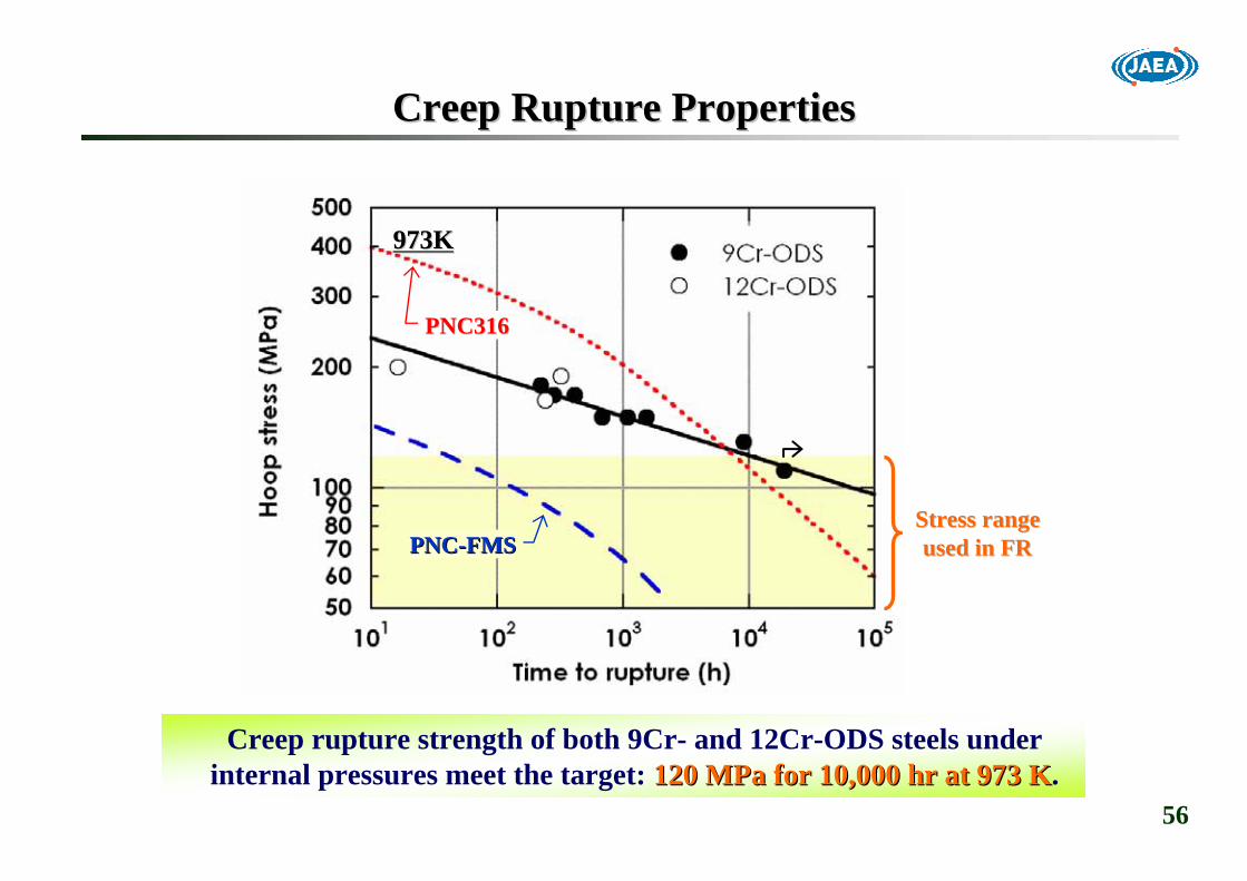
Creep Rupture PropertiesCreep Rupture Properties
Creep rupture strength of both 9Cr- and 12Cr-ODS steels under internal pressures meet the target: 120 120 MPaMPa for 10,000 hr at 973 Kfor 10,000 hr at 973 K.
PNC316PNC316
PNCPNC--FMSFMSStress rangeStress rangeused in FRused in FR
973K973K

57
0
1
2
3
0 1000 2000 3000 4000 5000 6000 7000 8000t (hr)
205MPa180MPa
155MPa
140MPa
700℃
破損
Creep Curves of 9CrCreep Curves of 9Cr--ODS SteelODS Steel
Time (hr)Time (hr)
Stra
in (%
)St
rain
(%)
FailureFailure
Creep curves under axial stress show little ternary stagein both 9Cr- and 12Cr-ODS steels

58
Sodium Immersion Effect on Creep Rupture PropertySodium Immersion Effect on Creep Rupture Property
Na入り口
Na出口
Na浸漬試験部
Na
Internal creeprupture specimen(Pressurized tube)
Hegas 60mm
He gasdetector
Na outletNa outlet
Na inlet intoNa inlet intotesting vesseltesting vessel
in Airin Sodium
923K 973K
(*) Sodium flow rate : <0.001m/s(*) Sodium flow rate : <0.001m/s
--The 9CrThe 9Cr--ODS steel has superior sodium compatibility up to 973 KODS steel has superior sodium compatibility up to 973 Kin stagnant sodium condition.in stagnant sodium condition.--Decarburization and Ni intrusion will be more influential Decarburization and Ni intrusion will be more influential For the 9CrFor the 9Cr--ODS steel in flowing sodium and inODS steel in flowing sodium and in--pile conditions.pile conditions.

59
Chapter 6. Irradiation TestsChapter 6. Irradiation Tests
Step1. Material Specimen IrradiationsStep1. Material Specimen Irradiations-- Screening of candidate materialsScreening of candidate materials-- Fundamental investigation of irradiation behaviorFundamental investigation of irradiation behavior-- Material Strength StandardsMaterial Strength Standards
↓↓Step2. Fuel Pin IrradiationsStep2. Fuel Pin Irradiations-- Step 1 +Step 1 +-- Fuel to cladding mechanical/chemical interactionFuel to cladding mechanical/chemical interaction
↓↓Step3. Leading/Dedicated Subassembly IrradiationsStep3. Leading/Dedicated Subassembly Irradiations-- DemonstrationDemonstration

60
Material Irradiation Rig: OffMaterial Irradiation Rig: Off--line Typeline Type-- CMIR & SMIR CMIR & SMIR --
Lock NutLock NutHandling HeadHandling HeadSpringSpring
CompartmentCompartment
Wrapper TubeWrapper Tube
Spacer PadSpacer Pad
EntranceEntranceNozzleNozzle
EExample of xample of SSpecimen and pecimen and CCapsuleapsule EExample of xample of Miniature SMiniature Specimenpecimenand Hand Holderolder
SpacerSpacer
Cross section of StructureCross section of StructureMaterials Irradiation Rig (SMIR)Materials Irradiation Rig (SMIR)
CapsuleCapsule
SpecimenSpecimen
CompartmentCompartment(Single Tube)(Single Tube)
SpecimenSpecimenHolderHolder
Tie RodTie Rod
Cross section of CoreCross section of CoreMaterials Irradiation Rig (CMIR)Materials Irradiation Rig (CMIR)
CompartmentCompartment(Double Tube)(Double Tube)

61
Irradiation Effect on Tensile PropertyIrradiation Effect on Tensile Property
(a) Stress-strain curve (b) Uniform elongation
Strength and ductility levels of irradiated ODS steel cladding tubesare adequately maintained.
9Cr-ODS (unirrad.)
3dpa 14dpa 15dpa 7dpa
12Cr-ODS (unirrad.)

62
Fuel Pin Irradiations in EBRFuel Pin Irradiations in EBR--IIII
JAEA(PNC)JAEA(PNC)--DOE CollaborationDOE Collaboration
12 Fuel Pins12 Fuel Pins-- 1DK: 13Cr1DK: 13Cr--3W3W--0.5Ti0.5Ti--0.35Y2O30.35Y2O3--0.07Ex.O0.07Ex.O-- 1DS: 0.1C1DS: 0.1C--11Cr11Cr--3W3W--0.5Ti0.5Ti--0.5Y2O30.5Y2O3--0.1Ex.O0.1Ex.O-- Higher Smear Density MOX Fuel PelletsHigher Smear Density MOX Fuel Pellets-- PRW PRW
Irradiation: Nov.26, 1992Irradiation: Nov.26, 1992-- Sep.15, 1994Sep.15, 1994-- Two subassembly: SPATwo subassembly: SPA--1B, C21B, C2-- LHR: ~48 kW/m, Tcm:~640LHR: ~48 kW/m, Tcm:~640℃℃-- Burnup:~6.3 at%, Fluence:~24 Burnup:~6.3 at%, Fluence:~24 dpadpa
Post Irradiation ExaminationsPost Irradiation Examinations-- ProfilometryProfilometry, , CeramographyCeramography

63
Fuel Pin Irradiations in BORFuel Pin Irradiations in BOR--60 (1)60 (1)-- JAEAJAEA--RIAR Collaborative Work RIAR Collaborative Work --
■■Objectives- To investigate irradiation performance of ODS clad fuel pins- To demonstrate and confirm the integrity up to 150 GWd/t■■Specification of ODS Clad Fuel Pins
9.0 g/cm315 wt%Vibro-packed MOX fuel
9Cr-ODS12Cr-ODS
1,050 mm6.9 mm
LengthOuter diameterSmear densityPu/(Pu+U)FuelCladding
materialFuel pin
PRW (JAEA)PRW (JAEA) TIGTIG--End face fusion (RIAR)End face fusion (RIAR)450mm
1,050mm
■■Fuel Pin Structure and Manufacturing
RIAR: Research Institute of Atomic ReactorsRIAR: Research Institute of Atomic Reactors
64
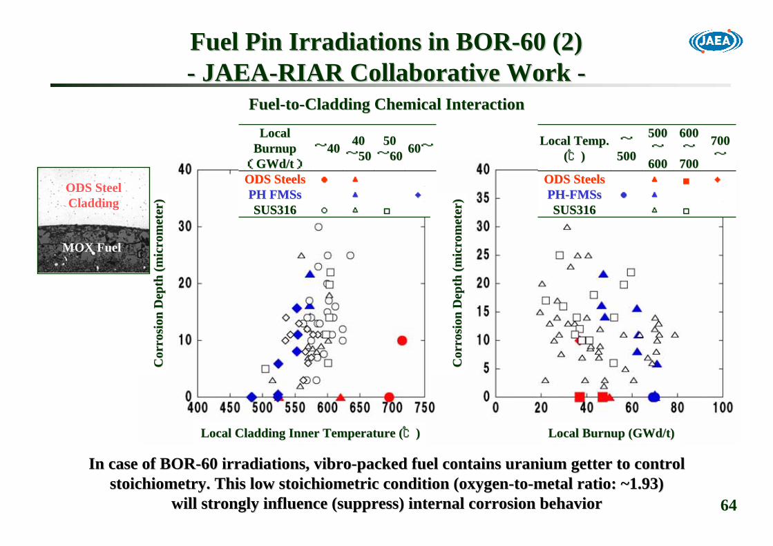
FuelFuel--toto--Cladding Chemical InteractionCladding Chemical Interaction
In case of BORIn case of BOR--60 irradiations, 60 irradiations, vibrovibro--packed fuel contains uranium getter to control packed fuel contains uranium getter to control stoichiometrystoichiometry. This low . This low stoichiometricstoichiometric condition (oxygencondition (oxygen--toto--metal ratio: ~1.93)metal ratio: ~1.93)
will strongly influence (suppress) internal corrosion behaviorwill strongly influence (suppress) internal corrosion behavior
□□△△○○SUS316SUS316◆◆▲▲PH PH FMSsFMSs
▲▲●●ODS SteelsODS Steels
6060~~5050~~6060
4040~~5050~~4040
Local Local BurnupBurnup((GWd/tGWd/t))
□□△△SUS316SUS316▲▲●●PHPH--FMSsFMSs
◆◆■■▲▲ODS SteelsODS Steels
707000~~
600600~~
707000
505000~~
606000
~~500500
Local Temp.Local Temp.((℃℃))
Fuel Pin Irradiations in BORFuel Pin Irradiations in BOR--60 (2)60 (2)-- JAEAJAEA--RIAR Collaborative Work RIAR Collaborative Work --
Local Local Cladding Inner Temperature (Cladding Inner Temperature (℃℃))
Co
Co r
rosi
on D
epth
(mic
rom
eter
)rr
osio
n D
epth
(mic
rom
eter
)
Co
Co r
rosi
on D
epth
(mic
rom
eter
)rr
osio
n D
epth
(mic
rom
eter
)
Local Local Burnup (Burnup (GWd/tGWd/t))
ODS SteelCladding
MOX Fuel
65
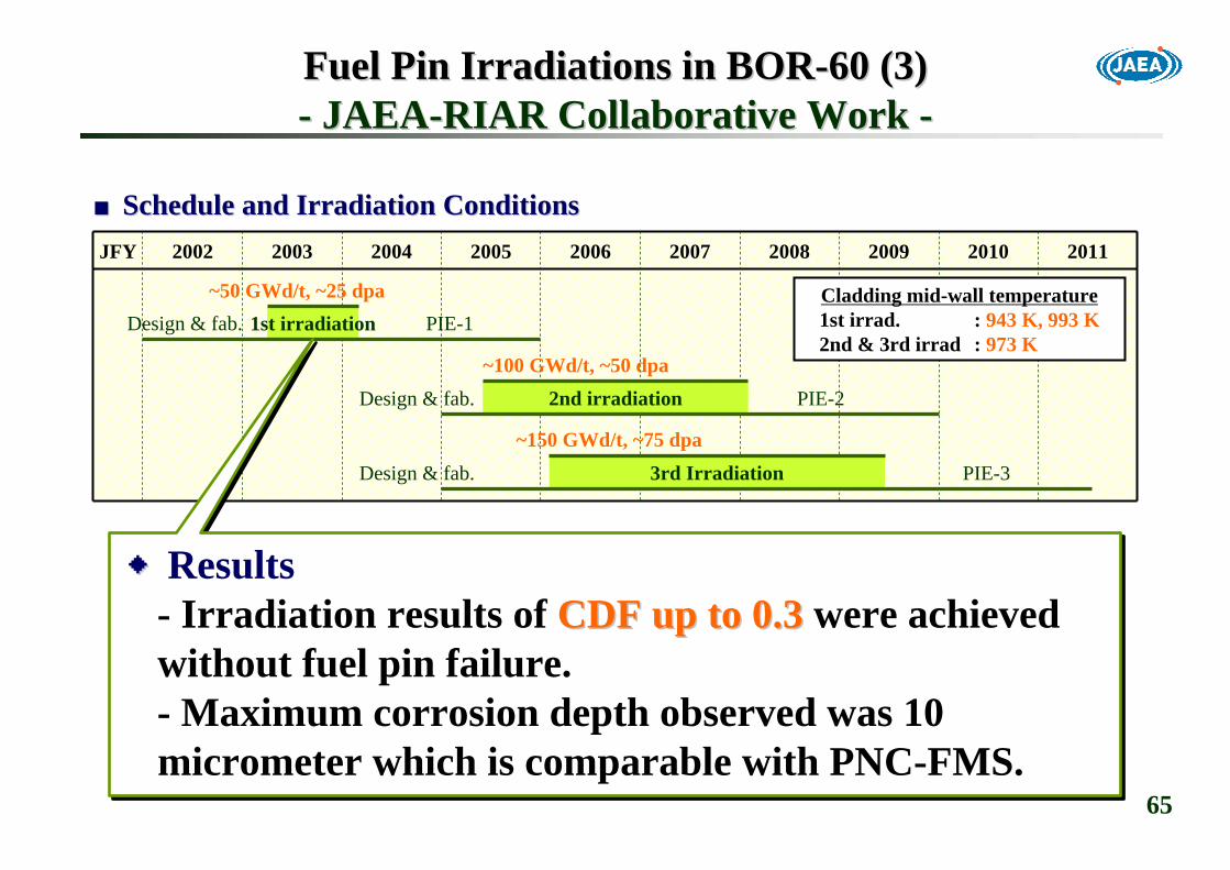
Fuel Pin Irradiations in BORFuel Pin Irradiations in BOR--60 (3)60 (3)-- JAEAJAEA--RIAR Collaborative Work RIAR Collaborative Work --
2011JFY 201020092008200720062005200420032002
~100 GWd/t, ~50 dpaPIE-2
PIE-3~150 GWd/t, ~75 dpa
PIE-1Design & fab.~50 GWd/t, ~25 dpa
Design & fab.
Design & fab.
2nd irradiation
3rd Irradiation
1st irradiationCladding mid-wall temperature1st irrad. : 943 K, 993 K2nd & 3rd irrad : 973 K
■■Schedule and Irradiation ConditionsSchedule and Irradiation Conditions
◆◆Results- Irradiation results of CDF up to 0.3CDF up to 0.3 were achieved without fuel pin failure.- Maximum corrosion depth observed was 10 micrometer which is comparable with PNC-FMS.

66
Capsule Rig for Advanced Fuel IrradiationCapsule Rig for Advanced Fuel Irradiation
CapsuleCapsule
Test pinTest pin
CompartmentCompartment
CapsuleCapsule--type Irradiation Rig (Typetype Irradiation Rig (Type--B)B)
He+ArHe+Ar gasgas
Test pinTest pinCapsuleCapsule
SodiumSodium
Fuel Pin Irradiations in JOYOFuel Pin Irradiations in JOYO-- Irradiation Rig Irradiation Rig --
1. Cladding tubes1. Cladding tubes-- Material: 9CrMaterial: 9Cr--ODSODS-- OD8.5mm x ID7.5mmOD8.5mm x ID7.5mm
2. Fuel pellets2. Fuel pellets-- (U, Pu)O(U, Pu)O22--xx (O/M = high & low)(O/M = high & low)-- OD7.3mm x ID2.2mmOD7.3mm x ID2.2mm-- Fuel column length : 400mmFuel column length : 400mm
3. Irradiation conditions3. Irradiation conditions-- Target LHR: 450W/cmTarget LHR: 450W/cm-- Target Clad temp.: 700Target Clad temp.: 700℃℃-- Target burnup: ~220GWd/tTarget burnup: ~220GWd/t

67
PRW Technology (1)PRW Technology (1)
*: Electrical resistance heating of the components while maintaining a continuous force sufficient to forge weld without melting.
AsAs--receivedreceived Tp:1,713KTp:1,713K
Argon Gas Bubble PrecipitationArgon Gas Bubble Precipitationby Over Heatingby Over Heating
Photographs are taken by Fuel Technology Research and DevelopmenPhotographs are taken by Fuel Technology Research and Development Section, Fuel Technology Department,t Section, Fuel Technology Department,Plutonium Fuel Development Center, Tokai Research and DevelopmenPlutonium Fuel Development Center, Tokai Research and Development Centert Center
TIG WeldingTIG Welding
Laser WeldingLaser Welding
Loss of OriginalLoss of OriginalMicrostructureMicrostructure
Blow HolesBlow Holes
When ODS steels are heated far beyond 1,473 K (1,200When ODS steels are heated far beyond 1,473 K (1,200℃℃),),nanonano--meter size meter size dispersoidsdispersoids will coarsen and lose dispersion strengtheningwill coarsen and lose dispersion strengthening
effectseffects and and argon gas bubble will precipitate at grain boundaryargon gas bubble will precipitate at grain boundary. . ↓↓
PPressurized ressurized RResistance esistance WWelding (PRW) Process*elding (PRW) Process*

68
PRW Technology (2)PRW Technology (2)
■■Welding Process
Ultrasonic InspectionUltrasonic Inspection
CladdingCladding
EndEnd--plugplug
Available for fuel pin endAvailable for fuel pin end--plugs and pressurized tube specimensplugs and pressurized tube specimens

69
Schedule of JOYO Irradiation TestsSchedule of JOYO Irradiation Tests
20072007 20082008 20092009 2010201020020066 20122012 20132013 20142014 2015201520201111 20120166
CMIRCMIR66
CMIRCMIR77
MARICOMARICO22
CMIRCMIR88
CMIRCMIR99
CMIRCMIR1010
CMIRCMIR1111
30 dpa30 dpa
PinPin(B12)(B12)
PinPin(B12)(B12)
PinPin(B12)(B12)
33--66 77--1111 1212--1616 1717--2121 2222--2626 2727--3131
PinPin(B12)(B12)
MARICOMARICO33
MARICOMARICO44
40 dpa40 dpa 90 dpa90 dpa 140 dpa140 dpa 190 dpa190 dpa 240 dpa240 dpa 270 dpa270 dpa
50 dpa50 dpa 90 dpa90 dpa
JOYO ReactorOperation
50 dpa50 dpa40 40 GWd/tGWd/t
100 dpa100 dpa90 90 GWd/tGWd/t
150 dpa150 dpa130 130 GWd/tGWd/t
250 dpa250 dpa220 220 GWd/tGWd/t
MaterialSpecimensIrradiations
Fuel PinsIrradiations
CYCY
Bundle (CX)Bundle (CX)BundleDemonstrations
OnOn--LineLine OffOff--LineLine OffOff--LineLine
<Scheduled at beginning of <Scheduled at beginning of FaCTFaCT project>project>
InterimInterimExaminationsExaminations

70
Chapter 7. Future Mass ProductionChapter 7. Future Mass Production
OD8.5mmOD8.5mm××L3,000mmL3,000mmCore Fuel Pin GeometryCore Fuel Pin Geometry
~7,000 kg/year**~7,000 kg/year**Weight of the TubesWeight of the Tubes~24,000 /year*~24,000 /year*Number of the TubesNumber of the Tubes
~26 month~26 monthOperation Cycle LengthOperation Cycle Length~800~800Fuel SubassemblyFuel Subassembly255255Core Fuel Pins/SubassemblyCore Fuel Pins/Subassembly
CFBRCFBROptimistic Estimation of Market Scale for ODS Steel Cladding TubOptimistic Estimation of Market Scale for ODS Steel Cladding Tubeses
**: does not include loss in manufacturing and fuel pin fabricatio: does not include loss in manufacturing and fuel pin fabrication processes.n processes.**: The weight of raw steel powders may be three times larger th**: The weight of raw steel powders may be three times larger than that of products.an that of products.
JOYO Irradiation Tests: 24 tubes/year (4.4kg)JOYO Irradiation Tests: 24 tubes/year (4.4kg)↓↓
ScaleScale--up of factor 1,000 is necessary for commercialization!!up of factor 1,000 is necessary for commercialization!!
71
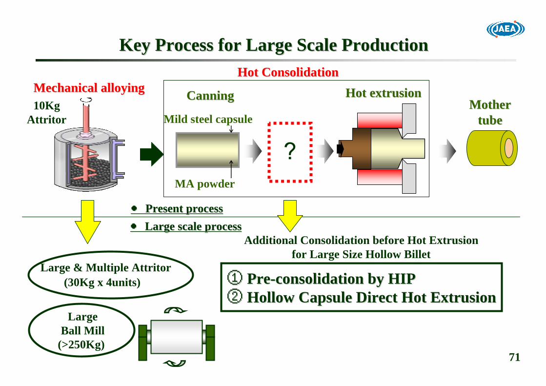
Key Process for Large Scale ProductionKey Process for Large Scale Production
Large & Multiple Attritor(30Kg x 4units)
LargeBall Mill
(>250Kg)
①① PrePre--consolidation by HIPconsolidation by HIP②② Hollow Capsule Direct Hot ExtrusionHollow Capsule Direct Hot Extrusion
●● Large scale processLarge scale process●● Present processPresent process
Mother tube
MA powder
Mild steel capsuleMotherMother
tubetube
Hot extrusion Hot extrusion CanningCanning
Additional Consolidation before Hot Extrusionfor Large Size Hollow Billet
Mechanical alloyingMechanical alloyingHot ConsolidationHot Consolidation
10KgAttritor
?
72
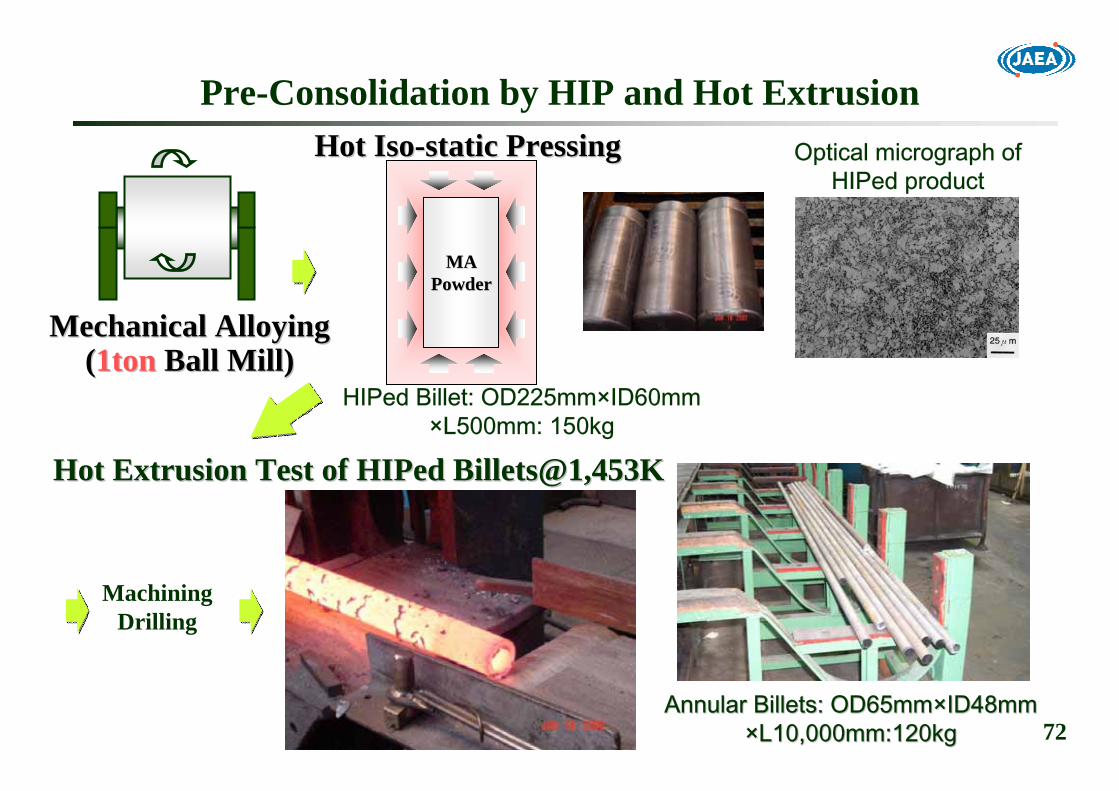
Pre-Consolidation by HIP and Hot Extrusion
MAMAPowderPowder
Hot Hot IsoIso--static Pressingstatic Pressing
MachiningDrilling
Hot Extrusion Test of Hot Extrusion Test of HIPedHIPed Billets@1,453KBillets@1,453K
HIPed Billet: OD225mm×ID60mm×L500mm: 150kg
Annular Billets: OD65mmAnnular Billets: OD65mm××IDID48mm48mm××LL10,000mm:120kg10,000mm:120kg
Mechanical AlloyingMechanical Alloying((1ton1ton Ball Mill)Ball Mill)
Optical micrograph ofHIPed product

73
Direct Hot Extrusion by Hollow CapsulePowder FillingPowder Filling
Annular Billets:OD32mmAnnular Billets:OD32mm××ID21mmID21mm××L2,000mm:7.3kgL2,000mm:7.3kg
OD147mm×ID32mm×L590mm:30kgHotHot--Extrusion 2,000ton PressExtrusion 2,000ton Press
@1,423K, Extrusion Ratio 13 @1,423K, Extrusion Ratio 13
AssemblingAssembling
High Chromium Steel LinerCross Section

74
Conclusions: 1Conclusions: 1CandidateCandidateMartensiticMartensitic 9Cr9Cr--ODS steel: ODS steel: Primary Primary Fully Fully ferriticferritic 12Cr12Cr--ODS steel: ODS steel: SecondarySecondary
Alloy Design: Alloy Design: Strength, Ductility, Microstructure ControlStrength, Ductility, Microstructure Control-- Phase and Grain Morphology Control: Phase and Grain Morphology Control: C,CrC,Cr, (, (Ex.OEx.O))-- Solution & Dispersion Hardening : W, Ti, YSolution & Dispersion Hardening : W, Ti, Y22OO33, , Ex.OEx.O
Microstructure Control: Microstructure Control: -- NanoNano--size oxide particles precipitate during PM processsize oxide particles precipitate during PM process-- Grain morphology must be controlled during tubing processGrain morphology must be controlled during tubing process-- 9Cr9Cr--ODS: Alpha to Gamma TransformationODS: Alpha to Gamma Transformation
→→ Cooling Rate ControlCooling Rate Control-- 12Cr12Cr--ODS: RecrystallizationODS: Recrystallization
→→ Two Step Heat TreatmentTwo Step Heat Treatment

75
Conclusions: 2Conclusions: 2
Mechanical PropertiesMechanical Properties-- Tensile and Creep Rupture Strength met the Initial TargetTensile and Creep Rupture Strength met the Initial Target-- Environmental EffectsEnvironmental Effects
Manufacturing Process for Future Mass ProductionManufacturing Process for Future Mass Production-- Screening Feasible TechnologiesScreening Feasible Technologies
Larger Size HotLarger Size Hot--Extruded Extruded BilletsBillets→→ ○○PrePre--consolidation by HIPconsolidation by HIP→→ △△Direct Hollow Capsule ExtrusionDirect Hollow Capsule Extrusion
Irradiation TestsIrradiation Tests-- Material Specimen Irradiations in JOYO in progressMaterial Specimen Irradiations in JOYO in progress-- Fuel Pin Irradiation Tests in BORFuel Pin Irradiation Tests in BOR--60 since 200360 since 2003-- PRW technologyPRW technology
76
Manufacturing Technology Development for Mass ProductionManufacturing Technology Development for Mass Production-- Applicable for the annual production size:~10,000 tubesApplicable for the annual production size:~10,000 tubes-- Larger Mother Tube Volume Larger Mother Tube Volume -- Longer Final ProductLonger Final Product-- Quality AssuranceQuality Assurance
Demonstration of Demonstration of HighHigh Burnup CapabilityBurnup Capability-- Material Specimen Irradiations in JOYO up to 250 Material Specimen Irradiations in JOYO up to 250 dpadpa-- Fuel Pin Irradiations in BORFuel Pin Irradiations in BOR--60 to 2009; 150GWd/t/75dpa60 to 2009; 150GWd/t/75dpa-- Fuel Pin Irradiations in JOYO; ~180GWd/t/~210dpaFuel Pin Irradiations in JOYO; ~180GWd/t/~210dpa-- Upgrading Material Strength StandardUpgrading Material Strength Standard
Activity in Activity in FaCTFaCT Project by 2015Project by 2015

77
Project ScheduleProject Schedule
Evaluate and Select Innovative Technologies by Evaluate and Select Innovative Technologies by 20102010: ODS clad fuel pin data at 150GWd/t and evaluation of high burn: ODS clad fuel pin data at 150GWd/t and evaluation of high burnup capabilityup capabilityEstablish Innovative Technologies by Establish Innovative Technologies by 2015: 2015: ODS clad fuel pin data at 250GWd/t and fuel pin bundle irradiatiODS clad fuel pin data at 250GWd/t and fuel pin bundle irradiation at medium burnupon at medium burnup
Demonstrate Innovative Technologies by Demonstrate Innovative Technologies by 2025: 2025: Fuel pin bundle/subassembly demonstration in MONJUFuel pin bundle/subassembly demonstration in MONJU
2045204520352035202520252015201520052005 20102010
Evaluation and ScreeningEvaluation and Screeningof Innovative Technology of Innovative Technology
CommercialCommercialReactorReactor
Design, ConstructionDesign, Construction
Design, ConstructionDesign, Construction
EstablishmentEstablishmentof Innovative Technology of Innovative Technology Demonstration & CommercializationDemonstration & Commercialization
DemonstrationDemonstrationReactorReactor OperationOperation
OperationOperation
ManufacturingManufacturingTechnologyTechnology
IrradiationIrradiationTestTest
Engineering scaleEngineering scale Commercial productionCommercial productionCommercialCommercial--scalescale
PropertiesPropertiesEvaluationEvaluation
Fuel pin (BORFuel pin (BOR--60)60)
OutOut--ofof--pile testpile test
Material, Fuel pin and Fuel pin bundle (JOYO)Material, Fuel pin and Fuel pin bundle (JOYO)
Fuel pin bundle (MONJU)Fuel pin bundle (MONJU)
MONJU driver fuelMONJU driver fuel
▲▲MSS upgrade for MONJU driver & DFBR fuelMSS upgrade for MONJU driver & DFBR fuel
JFYJFY

78
[1] S. [1] S. UkaiUkai, S. Mizuta, M. Fujiwara, T. Okuda, T. Kobayashi, J. , S. Mizuta, M. Fujiwara, T. Okuda, T. Kobayashi, J. NuclNucl. Sci. Technol., Vol.39, No.7, pp.778. Sci. Technol., Vol.39, No.7, pp.778--788 (2002).788 (2002).[2] J. Bottcher, S. Ukai, M. Inoue, Nucl. Technol.,Vol.138, pp.2[2] J. Bottcher, S. Ukai, M. Inoue, Nucl. Technol.,Vol.138, pp.23838--245 (2002).245 (2002).[3] S. Ukai, H. Hatakeyama, S. Mizuta, M. Fujiwara, T. Okuda, J.[3] S. Ukai, H. Hatakeyama, S. Mizuta, M. Fujiwara, T. Okuda, J. Nucl. Mater.,Vol.307Nucl. Mater.,Vol.307--311, pp.758311, pp.758--762 (2002).762 (2002).
[4] S. Ukai, T. Kaito, S. Ohtsuka, T. Narita, M. Fujiwara, T. Ko[4] S. Ukai, T. Kaito, S. Ohtsuka, T. Narita, M. Fujiwara, T. Kobayashi, bayashi, ISIJ International, Vol.43, No.12, pp.2038ISIJ International, Vol.43, No.12, pp.2038--2045 (2003).2045 (2003).
[5] T. [5] T. YoshitakeYoshitake, Y. Abe, N. , Y. Abe, N. AkasakaAkasaka, S. , S. OhtsukaOhtsuka, S. , S. UkaiUkai, A. Kimura, J. , A. Kimura, J. NuclNucl. Mater., Vol.329. Mater., Vol.329--333, pp.342333, pp.342--346 (2004).346 (2004).[6] S. Ohtsuka, S. Ukai, M. Fujiwara, T. Kaito, T. Narita, J. Nu[6] S. Ohtsuka, S. Ukai, M. Fujiwara, T. Kaito, T. Narita, J. Nucl. cl. Mater., Vol.329Mater., Vol.329--333, pp.372333, pp.372--376 (2004).376 (2004).[7] E. Yoshida, S. Kato, J. Nucl. [7] E. Yoshida, S. Kato, J. Nucl. Mater., Vol.329Mater., Vol.329--333, pp.1393333, pp.1393--1397 (2004).1397 (2004).[8] M. Seki, K. [8] M. Seki, K. HirakoHirako, S. , S. KonoKono, Y. , Y. KiharaKihara, T. , T. KaitoKaito, S. , S. UkaiUkai, J. , J. NuclNucl. Mater., Vol.329. Mater., Vol.329--333, pp.1534333, pp.1534--1538 (2004).1538 (2004).[9] T. Narita, S. [9] T. Narita, S. UkaiUkai, T. , T. KaitoKaito, S. , S. OhtsukaOhtsuka, T. , T. Kobayashi,JKobayashi,J. . NuclNucl. Sci. Technol., Vol.41, No.10, pp.1008. Sci. Technol., Vol.41, No.10, pp.1008--1012 (2004).1012 (2004).[10] S. Yamashita, N. [10] S. Yamashita, N. AkasakaAkasaka, S. , S. OhnukiOhnuki, J. , J. NuclNucl. Mater., Vol.329. Mater., Vol.329--333, pp.377333, pp.377--381 (2004).381 (2004).
[11] S. [11] S. UkaiUkai, T. , T. KaitoKaito, M. Seki, A. A. , M. Seki, A. A. MayorshinMayorshin, O. V. , O. V. ShishalovShishalov, J. , J. NuclNucl. Sci. Technol., Vol.42, No.1, pp.109. Sci. Technol., Vol.42, No.1, pp.109--122 (2005).122 (2005).[12] T. Narita, S. [12] T. Narita, S. UkaiUkai, T. , T. KaitoKaito, S. , S. OhtsukaOhtsuka, M. Fujiwara, J. , M. Fujiwara, J. NuclNucl. Sci. Technol., Vol.42, No.9, pp.825. Sci. Technol., Vol.42, No.9, pp.825--832 (2005).832 (2005).[13] T. [13] T. KaitoKaito, S. , S. UkaiUkai, S. , S. OhtsukaOhtsuka, T. Narita, GLOBAL2005, Paper No.169, October 9, T. Narita, GLOBAL2005, Paper No.169, October 9--13, 2005, Tsukuba, Japan (2005).13, 2005, Tsukuba, Japan (2005).[14] S. [14] S. OhtsukaOhtsuka, S. , S. UkaiUkai, H. , H. SakasegawaSakasegawa, M. Fujiwara, T. , M. Fujiwara, T. KaitoKaito, T. Narita, Mater. Trans., Vol.46, No.3, pp.487, T. Narita, Mater. Trans., Vol.46, No.3, pp.487--492 (2005)492 (2005)[15] S. [15] S. OhtsukaOhtsuka, S. , S. UkaiUkai, M. Fujiwara, T. , M. Fujiwara, T. KaitoKaito, T. Narita, J. Phys. Chem. Solids., Vol.66, pp.571, T. Narita, J. Phys. Chem. Solids., Vol.66, pp.571--575 (2005).575 (2005).
[16] S. [16] S. UkaiUkai, T. , T. KaitoKaito, S. , S. OhtsukaOhtsuka, T. Narita, H. , T. Narita, H. SakasegawaSakasegawa,,Transactions of the 2006 ANS Annual Meeting, June 4Transactions of the 2006 ANS Annual Meeting, June 4--8, 2006, Reno, USA (2006).8, 2006, Reno, USA (2006).
[17] S. [17] S. OhtsukaOhtsuka, S. , S. UkaiUkai, H. , H. SakasegawaSakasegawa, M. Fujiwara, T. , M. Fujiwara, T. KaitoKaito, T. Narita, J. , T. Narita, J. NuclNucl. Mater., Vol.367. Mater., Vol.367--370, pp.160370, pp.160--165 (2007)165 (2007)[18] T. [18] T. KaitoKaito, S. , S. OhtsukaOhtsuka, M. Inoue, GLOBAL2007, Paper No.005_175716, September 9, M. Inoue, GLOBAL2007, Paper No.005_175716, September 9--13, 2007, Idaho, USA (2007).13, 2007, Idaho, USA (2007).
Representative PublicationsRepresentative Publications