Development status of metallic, dispersion and non … · dispersion and non-oxide advanced and...
96
IAEA-TECDOC-1374 Development status of metallic, dispersion and non-oxide advanced and alternative fuels for power and research reactors September 2003
Transcript of Development status of metallic, dispersion and non … · dispersion and non-oxide advanced and...

IAEA-TECDOC-1374
Development status of metallic, dispersion and non-oxide
advanced and alternative fuels for power and research reactors
September 2003

The originating Section of this publication in the IAEA was:
Nuclear Fuel Cycle and Materials Section International Atomic Energy Agency
Wagramer Strasse 5 P.O. Box 100
A-1400 Vienna, Austria
DEVELOPMENT STATUS OF METALLIC, DISPERSION AND NON-OXIDE ADVANCED AND ALTERNATIVE FUELS FOR POWER AND RESEARCH REACTORS
IAEA, VIENNA, 2003 IAEA-TECDOC-1374ISBN 92–0–110303–4
ISSN 1011–4289© IAEA, 2003
Printed by the IAEA in Austria September 2003

FOREWORD
The current thermal power reactors use less than 1% of the energy contained in uranium. Long term perspectives aiming at a better economical extraction of the potential supplied by uranium motivated the development of new reactor types and, of course, new fuel concepts. Most of them dated from the sixties including liquid metal cooled fast (FR) and high temperature gas cooled (HTGR) reactors. Unfortunately, these impulses slowed down during the last twenty years; nuclear energy had to face political and consensus problems, in particular in the United States of America and in Europe, resulting from the consequences of the TMI and Chernobyl accidents. Good economical results obtained by the thermal power reactors also contributed to this process. During the last twenty years mainly France, India, Japan and the Russian Federation have maintained a relatively high level of technological development with appropriate financial items, in particular, in fuel research for the above mentioned reactor types. China and South Africa are now progressing in development of FR/HTGR and HTGR technologies, respectively.
The purpose of this report is not only to summarise knowledge accumulated in the fuel research since the beginning of the sixties. This subject has been well covered in literature up to the end of the eighties. This report rather concentrates on the "advanced fuels " for the current different types of reactors including metallic, carbide and nitride fuels for fast reactors, so-called “cold” fuels and fuels to burn excessive ex-weapons plutonium in thermal power reactors, alternative fuels for small size and research reactors. Emphasis has been put on the aspects of fabrication and irradiation behaviour of these fuels; available basic data concerning essential properties that help to understand the phenomena have been mentioned as well. This report brings complementary information to the earlier published monographs and concerns developments carried out after the early eighties until the present days. The aspects of HTGR fuels, as well as partitioning and transmutation (P&T) of minor actinides and relative specific fuels have not been addressed.
The International Atomic Energy Agency’s (IAEA) Division of Nuclear Fuel Cycle and Waste Technology has been closely involved for many years in the above mentioned activities in the framework of the Advisory Group on Advanced Fuel Technology and Performance (fast reactor fuels) and Technical Working Group on Water Reactor Fuel Performance and Technology (thermal power reactor fuels). Apart from the progress made during the last decade, this report summarizes technological approaches, out-of-pile and in-pile properties of many types of advanced non-oxide fuels. It is expected that the report will provide IAEA Member States and their nuclear engineers with useful information and will preserve knowledge in the area for future developments.
The review was prepared by a group of experts in the field from Germany, India and the Russian Federation and supported by information from specialists in Japan, Switzerland and the IAEA engaged in non-oxide fuel developments and related subjects. Special thanks are extended to A. Stanculesky of the IAEA for his patience and skills in correcting the many textual contributions and revisions. The IAEA officer responsible for the organization and compilation of this TECDOC was V. Onoufriev of the Division of Nuclear Fuel Cycle and Waste Technology.

EDITORIAL NOTE
The use of particular designations of countries or territories does not imply any judgement by the publisher, the IAEA, as to the legal status of such countries or territories, of their authorities and institutions or of the delimitation of their boundaries.
The mention of names of specific companies or products (whether or not indicated as registered) does not imply any intention to infringe proprietary rights, nor should it be construed as an endorsement or recommendation on the part of the IAEA.

CONTENTS
CHAPTER 1. INTRODUCTION............................................................................................... 1 References to Chapter 1 ............................................................................................................. 3
CHAPTER 2. ADVANCED CERAMIC NON-OXIDE FUELS FOR FAST REACTORS ..... 5
2.1. Introduction .................................................................................................................. 5 2.2. Fuel design ................................................................................................................... 72.3. Fabrication experience ................................................................................................. 8
2.3.1. Synthesis of MC & MN ..................................................................................... 92.3.2. Consolidation of MC and MN ......................................................................... 142.3.3. Sol-gel microsphere pelletisation (SGMP) of
MC and MN pellets .......................................................................................... 15 2.4. Out-of-pile properties................................................................................................. 15
2.4.1. Thermal stability of MN fuel ........................................................................... 17 2.4.2. Thermal conductivity ....................................................................................... 18 2.4.3. Thermal expansion........................................................................................... 202.4.4. Hot hardness and creep .................................................................................... 20 2.4.5. Out-of-pile chemical compatibility .................................................................. 21
2.5. Irradiation testing ....................................................................................................... 222.5.1. He-bonded carbide ........................................................................................... 23 2.5.2. Na-bonded carbide ........................................................................................... 24 2.5.3. He- and Na-bonded nitride............................................................................... 24 2.5.4. Fuel swelling .................................................................................................... 25 2.5.5. Fission gas release............................................................................................ 27 2.5.6. Carburization of clad materials ........................................................................ 28
2.6. Fuel pin performance modelling ................................................................................ 30 2.7. Reprocessing .............................................................................................................. 31
2.7.1. Reprocessing by Purex process ........................................................................ 31 2.7.2. Reprocessing by pyrometallurgy...................................................................... 32 2.7.3. A head-end gaseous oxidation process ............................................................ 32
2.8. MC and MN: Status and development trends ............................................................ 33 References to Chapter 2 ........................................................................................................... 34
CHAPTER 3. ADVANCED METALLIC FUELS FOR FAST REACTORS......................... 41
3.1. Introduction ................................................................................................................ 41 3.2. Out-of-pile properties................................................................................................. 42 3.3. Irradiation behavior .................................................................................................... 433.4. Reprocessing of fuel................................................................................................... 47
References to Chapter 3 ........................................................................................................... 47
CHAPTER 4. ADVANCED AND ALTERNATIVE FUELS FOR LWRs............................. 49
4.1. Metal type fuels (U3Si, U-Nb-Zr, U-Mo)................................................................... 49 4.2. METMET fuels .......................................................................................................... 57 4.3. Uranium CERMET fuels of the type Al + UO2, Zr + UO2 ........................................ 61
References to Chapter 4 ........................................................................................................... 63
CHAPTER 5. METAL AND DISPERSION FUELS FOR SMALL SIZE NUCLEAR REACTORS.......................................................... 65
5.1. Metallic fuels.............................................................................................................. 65 5.2. Metal matrix associated to high density fuel and porosity......................................... 67
References to Chapter 5 ........................................................................................................... 69
CHAPTER 6. HIGH DENSITY FUELS FOR RESEARCH REACTORS ............................. 71
6.1. Introduction ................................................................................................................ 71 6.2. CERMET fuels........................................................................................................... 71 6.3. METMET fuels .......................................................................................................... 72
References to Chapter 6 ........................................................................................................... 74
CHAPTER 7. MODELING OF FUEL IRRADIATION PERFORMANCE ........................... 77 References to Chapter 7 ........................................................................................................... 81
CHAPTER 8. FUEL FOR INCINERATION OF WEAPON AND REACTOR GRADE PLUTONIUM ................................................................ 83
8.1. Ceramic diluents (CERCER) ..................................................................................... 83 8.2. Irradiation behavior of ceramic diluents and CERCER fuel ...................................... 86 8.3. Metal diluents for CERMET fuel............................................................................... 87
References to Chapter 8 ........................................................................................................... 89
CHAPTER 9. CONCLUSIONS............................................................................................... 91
ABBREVIATIONS.................................................................................................................. 93
CONTRIBUTORS TO DRAFTING AND REVIEW.............................................................. 95

CHAPTER 1
INTRODUCTION
Since the demonstration of the first nuclear fission chain reaction in the graphite moderated natural uranium “pile” in the University of Chicago in December 1942, nuclear fuels and reactor technology has come a long way and has blossomed as a safe, environment friendly industry for peaceful use of nuclear energy. By the end of year 2000, there were 438 operating nuclear power reactors in 30 countries producing 351 GW(e), which is nearly 17% of the electricity in the world [1.1]. In addition, nearly 600 research reactors have been constructed so far, of which nearly 225 are in operation in the world [1.2, 1.3]. Developing countries now account for one-third of operating research reactors and most of the reactors are under construction or planned. These non-power research reactors are used as neutron source for (i) production of radioisotopes, (ii) irradiation-testing of materials and (iii) basic studies.
Conventional and advanced fuels for the present generation research and power reactors are listed in Table 1.1.
Presently, light water reactors (LWRs) consisting of pressurised water reactors (PWRs) of the western type and the Russian type known as WWERs and boiling water reactors (BWRs) account for more than 90% of the operating reactors. These are followed by the pressurised heavy water reactors (PHWRs). The liquid metal cooled fast reactors (FRs), though few in number today, are likely to play a major role in the event of rapid growth of nuclear power industry. The gas cooled reactors (Magnox and AGRs) are restricted only to the UK and have not been covered in this report.
Amongst the research reactors, the box type materials test reactor MTR and TRIGA, and the standard Russian channel type reactor MR and swimming pool reactors IRT and WWR-M are most popular all over the world.
The advanced fuels development programme encompass the following activities:
• development of commercially viable fabrication flowsheets which are safe, reproducible and amenable to remotisation and automation;
• evaluation of out-of-pile thermophysical, thermodynamic and mechanical properties; • evaluation of out-of-pile chemical compatibility of fuel with cladding and coolant
materials at temperatures and for duration simulating the in-pile operating conditions envisaged;
• irradiation-testing followed by post-irradiation examination (PIE); • fuel pin modelling and development of fuel performance prediction codes; • development of safe and commercially viable flow sheets for reprocessing of spent fuel
and management of radioactive wastes produced in the fuel cycle.
The future reactor types and fuel cycle options in different countries will depend on resource utilization, environmental impact, safety, public acceptance, energy politics and sustainable energy supply. The present status and future trends in the nuclear fuel cycle and power reactors may be summarized as follows:
1

Thermal reactors, namely LWRs and PHWRs, will continue to play a significant role during the next 50 years and beyond — uranium supply looks to be sufficient up to 2050 with regard to Refs [1.4, 1.5]. By this date, fast reactors also may enter the competitive electricity market. In the near future, civilian plutonium obtained by reprocessing spent thermal reactor fuels will be recycled as mixed oxide (MOX) fuel mainly in LWRs for electricity production and degrading the plutonium. Weapon grade plutonium from dismantled warheads is likely to be used either as mixed oxide (MOX) fuel in thermal reactors or as inert matrix fuel for burning plutonium and not for breeding.
In research reactors, the Reduced Enrichment for Research and Test Reactor (RERTR) programme initiated by Department of Energy, USA in 1978 is being implemented all over the world. The objective of this programme is to replace high enriched uranium (HEU) based fuel by low enriched uranium (LEU:<20% 235U) fuel in order to avoid diversion of HEU for non-peaceful purposes.
Table 1.1. Conventional and advanced fuels for power and research reactors
Reactors Conventional Advanced/Alternative fuels FR HEU UO2
(U,Pu)O2HEU U-Fs
(U,Pu)C and (U,Pu)NU-Pu-Zr PuC-ZrC
LWR: BWR, PWR,
WWER, RBMK
LEU UO2 (<5%U-235) (U,Pu)O2 (<5% Puf)LEU UO2 (<5%U-235)
UO2+Zr UO2+Al (all <5% U-235)U3Si+Zr U3Si+Al UO2 or PuO2+ MgAl2O4UO2 or PuO2+ ZrO2ROX: PuO2 in ZrO2+ MgAl2O4
PHWR Natural UO2 (U, Pu)O2(Th,U-233)O2(ThO2-PuO2) (all <2.5% U-235, PuO2+SiC or Puf)PuO2+ ZrO2PuO2+Al2MgO4PuSiC
PPR(Portable Power Reactor)
HEU-LEU Caramel (Zr/UO2-plates) HEU U-80Zr (Rod fuel) HEU Al+UAlx
LEU UO2+ Zr LEU U-Mo+Zr and other alloys
Research reactors (U density: gU/cm3)HEU: 90% U-235 MEU: 36% U-235 LEU: <20% U-235
HEU Al+UAlx (1.7) HEU UZrHx (0.5) HEU U3O8+Al (1.3)HEU UO2+Al (2.5) MEU UO2+Al (3.5) LEU U3Si2+Al (4.8)U metal (natural)
LEU UAlx+Al (2.3) LEU UZrHx (3.7) LEU U3O8+Al (3.2) LEU UO2+Al (5.0) LEU U3Si2+Al (6.0) LEU UN+Al (7.0) LEU Al+U-Mo and other alloys (8.0g/cc)
2
For this, aluminium matrix dispersion fuels with high uranium density are being developed. The reference fuel is Al-U3Si2 with a uranium density of 4.8 g/cm3. However, R&D programmes are underway in the USA, Europe, the Russian Federation, Japan and the Republic of Korea to develop RERTR fuels of still higher uranium density in order to achieve high neutron flux similar to that of HEU based fuels.
REFERENCES TO CHAPTER 1
[1.1] INTERNATIONAL ATOMIC ENERGY AGENCY, Nuclear Power Reactors in the World, Reference Date Series No 2, IAEA, Vienna (2002).
[1.2] INTERNATIONAL ATOMIC ENERGY AGENCY, Directory of Nuclear Research Reactors, STI/PUB/1071, IAEA, Vienna (1998).
[1.3] INTERNATIONAL ATOMIC ENERGY AGENCY, Nuclear Research Reactors in the World, Reference Date Series No 3, IAEA, Vienna (2000).
[1.4] INTERNATIONAL ATOMIC ENERGY AGENCY, Analysis of Uranium Supply to 2050, STI/PUB/1104, IAEA, Vienna (2001).
[1.5] OECD NUCLEAR ENERGY AGENCY/INTERNATIONAL ATOMIC ENERGY AGENCY, Uranium 1999-Resources, Production and Demand, OECD/NEA, Paris (2000).
3
CHAPTER 2
ADVANCED NON-OXIDE CERAMIC FUELS FOR FAST REACTORS
2.1. Introduction
One of the major factors for commercial success of FR technology lies in developing plutonium-based fuels that would operate safely without failure up to high burnups (>10 at.%), produce electricity economically, breed fissile material efficiently and be relatively easy to fabricate and reprocess. For this, the heavy metal density, melting point, chemical stability, and thermal conductivity of FR fuels should be high. In addition, the FR fuels should have excellent chemical compatibility with sodium coolant and stainless steel fuel cladding tube. Mixed uranium plutonium oxide containing up to 30% PuO2 and UO2
containing highly enriched uranium (≥ 85% 235U) have been successfully used as driver fuels in most of the prototype FRs in the world. Industrial scale experience on fabrication, irradiation, reprocessing and refabrication of mixed oxide fuels has been established. However, the use of mixed oxide as driver fuel in commercial FRs is vulnerable mainly because of its low breeding ratio and in turn long doubling time (>25 years). The low thermal conductivity of oxide fuel is also a disadvantage.
Mixed uranium plutonium monocarbide (MC) and mononitride (MN) have been identified as advanced FR fuels, nearly three decades back, on the basis of their high heavy metal density, high breeding ratio (and in turn short doubling time), high thermal conductivity and excellent chemical compatibility with sodium coolant. MC and MN belong to the same family on the basis of their crystal structure (fcc, NaCl type) and similar physical and chemical properties. The monocarbides and mononitrides of uranium and plutonium have complete solid solubility. The international experience on carbide and nitride fuels has been very well documented in the proceedings of several international conferences and IAEA meetings [2.1-2.7]. The monographs, entitled "Science of Advanced LMFBR Fuels" by H.-J. Matzke [2.8] and “Nonoxide Ceramic Nuclear Fuels” by H. Blank [2.9], summarise practically all published information on UC, PuC, UN, PuN, MC and MN. However, compared to mixed oxide fuel, the experience on monocarbide and mononitride fuels is very limited. The quantity of MC and MN fuels fabricated so far all over the world would not exceed 1000 kg and 100 kg respectively and the number of fuel pins that have been irradiated would be less than 2000 and 200 for carbide and nitride respectively.
The research and development programmes on carbide and nitride fuels for FR were actively pursued in the USA, France, Germany, the United Kingdom and the Russian Federation during 1960s and 1970s and a little later in India and Japan. The investigations were, however, restricted to UC, UN, (U,Pu)C, and (U,Pu)N fuels with a maximum plutonium content of 20%. In Russia, a uranium monocarbide core was in operation in the BR-5 reactor from 1965 to 1971 and achieved a maximum burnup of 6.2 at.%. A large number of UN sub-assemblies were also successfully irradiated in BR-10 core up to a burnup of 9 at.%. In the BOR-60 reactor too, several UC, U(C,N), (U,Pu)C and (U,Pu)N test subassemblies were successfully irradiated to high burnup. In USA, nearly 700 helium-bonded and sodium-bonded fuel pins containing MC and MN pellets were successfully irradiated in EBR II and FFTF to high burnups in the range of 10–20 at.%. Most of these pins were He-bonded containing MC pellets. A limited number of test-irradiations were also carried out using “vibro-packed” MC pins.
5

Irradiation-testings of monocarbide and mononitride fuel pins have also been carried out in Rapsodie/Fortissimo and Phenix reactors in France, DFR in the UK, BR-2 in Belgium, KNK-II in Germany, HFR (Petten), Netherlands and JRR-2 and JMTR in Japan [2.10–2.13]. In none of these reactors mixed carbide or mixed nitride have been used as driver fuel. India is the first country in the world to develop a plutonium rich (Pu: 66%) mixed uranium plutonium monocarbide fuel and use the same as driver fuel in their fast breeder test reactor (FBTR) [2.14]. The carbide core is in operation since October 1985 and has so far seen an average burnup close to 50,000 MWd/t without any failure [2.15]. A second mixed carbide fuel core with somewhat lower plutonium content (52%) is under fabrication [2.16].
As carbide fuel has some disadvantages, which are discussed below, the concept of development and use of nitride fuel in future FRs has been accepted in the Russian Federation. It is considered using nitride fuel in BN-800 with sodium coolant, which startup is planned in year 2008, and in BREST-300 FR with lead coolant which is now under consideration.
The MC and MN fuel program has encompassed: (i) development of fabrication flow sheets based on "powder-pellet", “vibratory-compaction”(also known as “vi-pack”, “sphere-pack” or “vibro-sol” process) and "sol-gel microsphere pelletisation" (SGMP) processes, (ii) evaluation of out-of-pile thermophysical properties, e.g. coefficient of thermal expansion, thermal conductivity, hot hardness, creep etc. (iii) experiments on out-of-pile chemical compatibility with stainless steel cladding and sodium coolant, (iv) irradiation-testing and post-irradiationexamination, (v) reprocessing.
Table 2.1 provides an inter-comparison of MC and MN fuels for FRs. Though the density and most of the thermophysical properties of MC and MN are in the same range, the nitride fuel has the following advantages over the carbide:
• it is not as reactive and as pyrophoric as MC though MN is also susceptible to oxidation and hydrolysis; hence for handling MN, inert cover gas of commercial purity is acceptable unlike MC which requires ultra high purity (< 20 ppm each of O2 and H2O)N2, Ar or He atmosphere inside glove box, irradiated carbide fuel can burn on air;
• it is relatively easier to fabricate single phase MN since plutonium forms only the mononitride with nitrogen and the higher nitrides of uranium (UN2 and U2N3) are unstable and easy to dissociate to UN by high temperature (≥ 1673 K) treatment in vacuum or argon; uranium and plutonium have very stable higher carbides namely Pu2C3, PuC2, U2C3 and UC2; hence, fabrication of single phase monocarbide on an industrial scale is problematic;
• higher density of nitride allows to reach reproduction coefficient about of 1, nitride has a smaller swelling, better retaining of gas fission products than carbide;
• unlike MC, MN dissolves easily and completely in HNO3 and reprocessing of spent MN fuel is possible by the classical PUREX process.
The major problem of MN fuel is the formation of radioactive 14C by (n,p) reaction with 14Nand the high parasitic absorption of fast neutrons by N14. The problem of 14C could be avoided by using 15N. However, the process of 15N enrichment is expensive. The alternative way to resolve the 14C problem is to isolate the same during reprocessing, oxidise to CO2 and finally convert to CaCO3 and bury as high active solid waste.
6

Table 2.1. Inter-comparison of mixed uranium plutonium monocarbide (MC) and mononitride (MN) fuels for FRs [2.8]
Basis of Comparison (U0.8Pu0.2)C (U0.8Pu0.2)N
Density (g/cm3) 13.58 14.32
Melting point (K) 2750 3070 at 1 atm.of N2
Thermal conductivity (W/mK) 1000 K 1500 K 2000 K
18.820.621.2
15.818.020.1
Crystal structure NaCl (FCC) NaCl (FCC) Swelling Higher than MN Higher than MO2
Creep Lower than MN Lower than MO2
Powder Highly pyrophoric Less pyrophoric Handling Ar, N2 or He
(High purity) Ar, N2 or He(Commercial purity)
Dissolution in HNO3 & reprocessing
Difficult (formation of organic complex)
Easy (Compatible with PUREX process)
Carburization/nitridation of stainless steel cladding
M2C3 ≤20% & 0 ≤ 2000 ppm acceptable
0 + C ≤ 2000 ppm acceptable, M2N3 easy to avoid
Fabrication & irradiation experiences worldwide
< 2000 kg < 2000 pins(including Pu rich MC driver fuel for FBTR, India)
< 100 kg < 150 pins
2.2. Fuel design
On the basis of several irradiation-testing experiments carried out mostly in the USA during the period 1970–85, the following two designs have successfully emerged for MC and MN fuels:
• helium-bonded fuel pins containing either low density (80–85% theoretical density-TD) “fuel pellets”or vibro-packed “fuel microspheres” of high density,
• sodium-bonded fuel pins containing high density (≥ 95% TD) “fuel pellets”, often with a thin and perforated "shroud" tube in the annular gap between “pellet” and “cladding”.
7

In both designs stoichiometric or slightly hyperstoichiometric MC and stoichiometric MN pellets were used in order to avoid serious fuel-cladding compatibility problems. With liquid sodium bonding, the fuel-clad gap conductance improves significantly which could be exploited by using larger diameter fuel pellets, thereby reducing the doubling time. However, to prevent localized hot spots it is imperative that sodium wets the fuel and the cladding and that the sodium bond is free of gas bubbles or voids. The fabrication cost of Na-bonded “pellet-pins” is much higher than that of He-bonded pins.
The vibro-packed fuel pins have been successfully irradiated to high burnups in the USA and USSR. The packing density and in turn the smeared density of the fuel pin could be easily controlled in the range of 60–90% TD by packing fuel particles or microspheres of 1, 2 or 3 sizes. Fuel cladding mechanical interaction (FCMI) is lower for a vibratory compacted pin since the relatively loose structure of the particle bed allows the particles to relocate, thereby reducing the net axial and radial expansion. As a result, there are no circumferential ridges and stress concentration points, which are quite common in pellet-fuel-pins. However, in the event of a breach of “vibro-packed fuel pin”, early in life, the loose fuel particles or microspheres are likely to be washed out of the fuel pin, thereby contaminating the primary coolant circuit severely. The defect pin behaviour of He-bonded “pellet-pin”, in general, is expected to be superior compared to that of the “vibro-packed pins”.
Hence, He-bonded “pellet-pin” containing relatively low density (80–85% TD) fuel pellets has emerged as the reference design for MC and MN fuels for FR.
2.3. Fabrication experience
The different techniques of synthesis and consolidation of MC and MN are similar because these non-oxide actinide compounds are isostructural, completely solid soluble and have very similar physical, chemical and thermodynamic properties.
UC, PuC, (U,Pu)C, UN, PuN & (U,Pu)N are difficult and expensive to fabricate because of following main reasons. Firstly, the numbers of process steps is more compared to that of oxide fuel. Secondly, these actinide compounds are highly susceptible to oxidation and hydrolysis and are pyrophoric in powder form. The entire fabrication is, therefore, required to be carried out inside leak tight glove boxes maintained in an inert cover gas (N2, Ar, He etc) atmosphere containing minimal amounts of oxygen and nitrogen (< 20 ppm each). Thirdly, stringent control of the carbon contents is needed during the different stages of fabrication in order to avoid the formation of the unwanted metallic phase and for keeping higher carbides (M2C3 and MC2) within acceptable limits. Higher nitrides (M2N3 and MN2) dissociate to MN at elevated temperature (≥ 1400oC) in inert atmosphere and pose no problem.
The fabrication of UC, (U,Pu)C, UN and (U,Pu)N fuels all over the world has mostly been carried out on small batches (a few kilograms) mainly for preparation of samples for out-of-pile property evaluation and fabrication of test pins for in-pile irradiation. India is only the country in the world, so far, to use (U,Pu)C as driver fuel in a fast reactor and has a small pilot plant for production of (U,Pu)C and (U,Pu)N fuel pellets.
The two main steps for fabrication of UC, UN, PuC, PuN, MC and MN fuels are as follows:
• preparation of buttons, powders, clinkers, or sol-gel microspheres of the monocarbide or mononitride, starting either from the oxide or from the metal;
8

• consolidation of monocarbide or mononitride powders, granules or microspheres in the form of fuel pellets, followed by loading of the fuel pellet stack in cladding tube and encapsulation or vibro-packing of granules or microspheres in fuel cladding tube followed by encapsulation.
2.3.1. Synthesis of MC & MN
The following are the principal methods of synthesis of MC and MN [2.4–5, 2.17–18]:
• direct synthesis by arc-melting;
• hydriding-dehydriding of bulk metal (to form fine metal powder) followed by carburisation and nitridation with methane/propane and nitrogen for obtaining fine powders of MC and MN respectively;
• carbothermic reduction of oxide-carbon mixture in vacuum/argon and flowing nitrogen for preparation of MC and MN respectively.
The direct synthesis involves non-consumable electrode arc-melting of stoichiometric powder mixture of uranium, plutonium and carbon in vacuum or flowing argon for the synthesis of MC and powder mixture of uranium and plutonium in flowing nitrogen for the preparation of MN. Tungsten is the commonly used non-consumable electrode. However, tungsten has a tendency to erode and contaminate the melt. For the synthesis of MC, graphite is also used in place of tungsten. When a graphite electrode is used, it is difficult to control the carbon stoichiometry of MC because of the carbon pick up from the electrode by the melt. As a result, the higher carbides are always found in the MC buttons. The MC buttons are, therefore, crushed and treated with hydrogen in order to reduce all the higher carbides to MC and to remove any free carbon as methane. For MN, a nitrogen overpressure of 2MPa or more is needed; otherwise free metal is always present in the product. The main advantage of the melting method is the low oxygen impurity (≤ 0.02 wt.%) of the MC and MN end products. However, the method has not been pursued on an industrial scale because of economic reasons and for problems of safety. An additional disadvantage is that the buttons are to be remelted several times for obtaining a homogeneous end product.
For preparation of MC and MN by carburisation and nitridation of metal powder respectively, the massive metal is first converted into fine powders of high surface area by hydriding and dehydriding at 450–525 K and 800–1000 K respectively. This freshly produced metal powder can easily be carburised to MC by methane or propane or nitridated to MN by N2 at relatively low temperatures in the range of 1000–1100 K. The different chemical reactions involved in this process are:
M(massive) + x/2 H2 = MHx MHx = M(powder) + x/2 H2 M(powder) + CH4 = MC + 2 H2
M(powder) + ½ N2 = MN
This method of synthesis of MC and MN powders has two main attractions. First, the reaction temperatures are low. This has the added advantage of minimum plutonium losses by volatilization. Secondly, the end products are fine and highly reactive MC and MN powders, which can be directly compacted and sintered. The main disadvantage of this method is that
9

the starting materials are uranium and plutonium metals. In addition, the exothermic nature of hydriding reaction with metal powder makes its control difficult. Many laboratories have utilized this technique on a semi-production scale. For example, the MN powder used for the fabrication of MN test pins irradiated in EBR-II and the UC and UN powders for making test pins for the material test reactor in Japan, have been prepared by this method.
The carbothermic reduction of oxides is the most attractive route for large scale production and has, therefore, been studied extensively in all the laboratories associated with the development of MC and MN fuels. In the carbothermic reduction of oxide, a high degree of microhomogenity of the starting oxide-carbon mixture is necessary. Otherwise, localised deficiencies and excesses of carbon will lead to the formation of unwanted phases. The requisite homogenisation is achieved either by a ‘dry method’ involving prolonged milling and blending of the oxide-carbon powder-mixture followed by pelletizing or alternatively by a ‘wet chemical route’, popularly known as the ‘sol-gel’ process. In the ‘sol-gel’ route, gelled microspheres (100–200 micron) of oxide plus carbon are prepared from the nitrate solution of uranium and plutonium by ammonia external or internal gelation processes [2.5, 2.19].
Carbothermic synthesis of (U,Pu)C from oxide
The overall simplified chemical equation for the production of monocarbide by carbothermic reduction of oxide can be represented by the following reaction:
MO2 + 3C = MC + 2CO ↑
where MO2 is either a mechanical mixture or a solid solution of UO2- PuO2.
“Single-step, solid state synthesis in a static bed” is the simplest technique for preparation of MC. In this method, the MC end product will always contain M2C3 second phase and residual oxygen and nitrogen impurities. This is because oxygen and nitrogen act as carbon equivalents and replace 'C' in the MC lattice to form the compound (U,Pu) (OxNzC1-x-z), where ‘x’, z and their summation is less than 1.0.
Experimental results as well as equilibrium thermodynamic calculations have indicated that relatively oxygen free MC cannot really be prepared by the direct solid state carbothermic reduction of the oxide [2.20]. Irrespective of whether the starting material is a mechanical mixture or a solid solution of UO2 and PuO2, in the final stage of the carbothermic reduction process, mixed uranium plutonium monoxycarbide is formed, which cannot be completely reduced to MC.
During carbothermic reduction, the control of the partial pressure of carbon monoxide is very important since the evolution of this gas not only constitutes the primary reduction mechanism but also controls the kinetics of this reaction. Figure 2.1 illustrates the process steps followed in India for preparation of plutonium rich (U,Pu)C pellets for FBTR by the ‘single step’ “carbothermic synthesis” route in a static bed [2.14, 2.16].
The “two-step solid state synthesis in a static bed” is an improvement over the single step synthesis and aims at the preparation of single phase MC with very low oxygen and nitrogen contents and with practically no losses of plutonium by volatilization [2.21].
10

FIG. 2.1. Process steps followed in India for preparation of plutonium rich (U,Pu)C pellets for FBTR by the ‘single step’ “carbothermic synthesis” route in a static bed [2.14, 2.16].
M2C3, unlike MC, has very little oxygen and nitrogen solid solubility. The equilibrium CO pressure for the formation of M2C3 is reasonably high even at relatively low temperatures and also much higher than that of the formation of MC. M2C3, unlike MC, can therefore be prepared very easily. In the first step, carbothermic reduction at a relatively low temperature with excess carbon than what is needed for M2C3 formation ensures that only M2C3 is formed and the formation of M(OxNzC1-x-z) is avoided. Because of the low carbothermic reduction temperature, the plutonium losses are practically negligible. In the second step, the M2C3 is crushed, milled and treated with hydrogen at 1123 K in order to reduce it to MC and remove the free carbon as methane. By controlling the ratio of the partial pressures of methane and hydrogen in the second step, single phase MC as well as MC with controlled amounts of M2C3can be produced. The drawbacks of this method are a longer production time (because of the
11

additional step), explosion hazard associated with the use of hydrogen and the possibility of unwanted metallic phase by hydrogen reduction of MC.
The synthesis of MC by “reaction-sintering” was developed in Germany [2.22]. The process is carried out in three stages. In the first stage, UC is prepared by carbothermic reduction of UO2at 2073 K. In the second stage, plutonium-oxycarbide is produced by carbothermic reduction at a low temperature (1473 K) to minimize plutonium volalitization. And finally, in the third stage, uranium carbide and plutonium oxycarbide-carbon powders are blended, compacted and subjected to “reaction-sintering”. The sintered pellets were found to have microstructural inhomogeneity. In the interior of the pellet, a highly densified zone is seen. Further, because of the substantial release of carbon monoxide as a result of reaction during sintering, the sintered pellets contain a lot of open porosity.
Carbothermic synthesis of (U,Pu)N from oxide
The overall chemical reaction for carbothermic synthesis of MN starting from the oxide can be represented by the following equation:
MO2 + 2C + 1/2 N2 = MN + 2CO ↑
In the carbothermic synthesis of MN, N2 plays the dual role of the reactant and the carrier for the removal of CO. The reaction product will have the general formula (MN1-x-yCxOy). The oxygen and carbon retained in MN will depend on the partial pressures of nitrogen and carbon monoxide, flow rate of reacting gas (N2, N2 + H2), the oxide to carbon mole-ratio of the starting MO2-C mixture and whether hydrogen is used for removing the excess carbon [2.23]. The ideal way to obtain nearly single phase MN with very low oxygen, carbon and higher nitride is to use around 10% excess carbon in the oxide-carbon mixture, a synthesis temperature of 1500–1600oC in flowing N2, followed by N2 + H2 and Ar. The CO in the exhaust gas should be closely monitored. The process flowsheet generally followed for synthesis of (U,Pu)N from UO2 and PuO2 powders is given in Fig. 2.2. [2.23].
As initial materials separate oxides of uranium and plutonium or in common mixture received by decomposition of oxalates at 870–970 K are used. As carbon the soot, graphite scales or crushed graphite of reactor grade purity are used. For nitriding the high purity nitrogen is applied.
The initial oxides and carbon are mixed up in mills and are pressed at pressure 100–300 MPa. The tablets are located in the furnace and are heated up in a flow of nitrogen and hydrogen. Temperature of uranium nitride production is from 2020 to 2220 K, and mixed uranium —plutonium nitride is from 1820 to 1920 K. After end of nitriding process the product is cooled in the same atmosphere up to 1670 K to avoid formation of one and half uranium nitride. Received nitride is analyzed on the contents of oxygen and carbon, the X ray analysis is carried out.
Synthesis of (U,Pu)N from metal
The manufacturing technology of nitrides from metal uranium and plutonium is considered in Russia to be especially urgent in connection with utilization of nuclear weapon.
12

FIG. 2.2. Process flow sheet for preparation of (U,Pu)N pellets from UO2 & PuO2 powders [2.23].
The nitride preparation from initial metals is based on reactions:
2M + 3H = 2MH32MH3 + 1.5N2 = M2N3 + 3H22MH3 + N2 = 2MN + 3H22M + N2 = 2MN
13
The technological scheme considered by the Russian researchers is following [2.24]:
• preparation of initial metal uranium and plutonium (or preparation of an alloy),
• hydriding of metals or alloy at 500 K,
• nitriding at 720–820 K.
Wastes from manufacture of fuel tablets are directed on denitriding in vacuum at 950 K and then on repeated process of nitriding.
The nitride production is developed for continuous and periodic process [2.24].
2.3.2. Consolidation of MC and MN
The principal methods of consolidation of MC and MN microspheres or powders in the form of small diameter fast reactor fuel pins are :
• cold pelletisation of the powder or microspheres into pellets followed by sintering,
• direct pressing,
• vibratory compaction of the granules, microspheres or crushed clinkers in cladding tubes,
• sol-gel microsphere pelletisation.
In the fabrication process involving cold pelletisation followed by sintering, suitable binders and sintering aids (if any) are added to the milled powder and the milling is continued for several hours for proper homogenisation. The powder is then compacted into pellets (length to diameter ratio ~1.6), preferably in a double action press at 60–200 MPa, followed by sintering in argon or vacuum in the temperature range 1673–2173 K.
Pellets from MN with density 88–95 % from theoretical are produced by pressing at 100–300 MPa and sintering in vacuum or in an atmosphere from argon and nitrogen mixture at 1890–1870 K.
In the “direct pressing” route [2.25], the MC or MN clinkers after carbothermic synthesis are directly compacted and sintered thus avoiding the crushing and milling steps. This process generates fuel pellets with densities in the range of 80–88% TD, reduces oxygen contamination, risk of self-ignition, dust generation, radiation exposure to personnel, concentration of metallic impurities, etc. In France, the opportunity of manufacturing of mixed MN fuel by "direct pressing" rout was checked up on a laboratory line on manufacture of oxide fuel. The cores for two assemblies were produced. The cores contained 0.07–0.23% of oxygen and 0.009–0.080% of carbon. Density of cores was from 81 to 84% from theoretical. The considered variants are used at cores manufacturing for fuel elements of various designs. The cores from high density MN as a rule are intended for Na-bonded fuel pins, and low density MN cores for He-bonded fuel pins.
The vibratory compaction or vibro-sol route has several advantages over the “powder-pellet” route. First, the number of fabrication steps is lesser and there is maximum flexibility of
14

operation. Given two or three different sizes of particles, fuel cladding tubes of any internal dimensions can be vibro-filled to a wide range of smear densities (60–90% TD). Unlike the other methods, the questions of surface grinding of rods, centreless grinding of pellets and die or mold sizing for particular pins do not arise at all. The vi-pack route is amenable to automation and remotisation and avoids handling and generation of fine MC and MN powders, which are highly radiotoxic and pyrophoric.
2.3.3. Sol-gel microsphere pelletisation (SGMP) of MC and MN pellets
The SGMP process is a hybrid of the "Vibro-sol" and the "powder-pellet" routes, where the fabrication advantages of sol-gel process is combined with the in-pile performance advantages of "pellet-pin" design. The advantages of SGMP process are as follows:
• "radiotoxic dust hazard" and pyrophoricity hazard are minimised;
• dust-free and free-flowing microspheres facilitate automation and remotisation;
• fabrication steps for monocarbide and mononitride fuel pellets are significantly reduced as shown in Fig. 2.3;
• excellent microhomogenity is ensured in fuel pellets because U and Pu are mixed as nitrate solutions;
• fabrication of relatively low density pellets (∼85% T.D.) with "open" pore structure specified for He-bonded FR fuel pins is possible without addition of pore former.
The process flow sheet developed in India is outlined in Fig. 2.4 and consists of the following major steps [2.19]:
• preparation of hydrated gel-microspheres of UO3 + PuO2 and UO3 + PuO2 + C by "ammonia internal gelation" process, using hexamethylene tetra amine (HMTA) as ammonia generator, urea as a buffer and silicone oil at 90oC as gelation bath;
• carbothermic synthesis in vacuum and flowing N2/N2+H2 for preparation of press-feed microspheres of (U,Pu)C and (U,Pu)N respectively;
• cold-pelletisation and sintering.
The dust-free and free-flowing MC and MN microspheres are directly cold-pelletised at around 1200 MPa and sintered at 1700 0C in Ar + 8% H2 atmosphere.
2.4. Out-of-pile properties
A high confidence level on the fuel performance can only be reached from a good interpretation of the irradiation data followed by post-irradiation examinations. A prerequisitefor this aim is to have at disposal data on out-of-pile properties such as thermal conductivity or thermal diffusion that allows to understand the influence of parameters such as temperature, temperature gradient, stress, stress gradient, fission rate, impurities that are effective during operation.
15
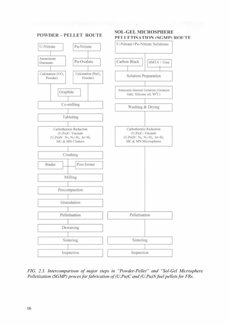
FIG. 2.3. Intercomparison of major steps in “Powder-Pellet” and “Sol-Gel Microsphere Pelletization (SGMP) proces for fabrication of (U,Pu)C and (U,Pu)N fuel pellets for FRs.
16

FIG 2.4. Flowsheet developed in India for fabrication of (U,Pu)O2, (U,Pu)C and (U,Pu)N by Sol-Gel Microsphere Pelletization (SGMP) process [2.19].
To the thermal properties has to be added mechanical properties data such as creep, coefficient of thermal expansion and chemical properties such as phase diagrams, melting point, vapour pressure, etc. Basically all these properties are strongly dependent on the microstructure and chemical composition of the sintered fuel pellets. Metallic impurities, oxygen, nitrogen and carbon can play a determining role in all data that are dependent on diffusion mechanisms.
2.4.1. Thermal stability of MN fuel
The thermal stability of MN (melting, dissociation point) is important for evaluation of its behavior under accident conditions. The view of the U-N phase diagrams depends on equilibrium pressure of nitrogen in system. At rather high pressure of nitrogen MN congruently melts, at reduction of pressure it is decomposed to a liquid phase of uranium and nitrogen. Temperature of MN decomposition is reduced at reduction of equilibrium pressure of nitrogen in system. The following dependencies and values for melting-disintegration points (T in K) were proposed [2.26, 2.27]:
UN T = 3075PN20.02832 for PN2 = 10-12 - 7.5 MPa
UxPu1-xN T = 2875 - 3023 for x = 1 and 0.8 at PN2 = 0.1 MPa U0.8Pu0.2N T=3050 for PN2 = 0.25 MPa
17

Equilibrium partial pressure of components were defined as function of temperature [2.28]:
UN lg(PN2) = 1.822 + 1.822.10-3T - 2343.4/T for T from 1400 to 3107 K lg(PN2) = -3.2.104/T + 8.9 for T from 1600 to 3123 K
lg(PN2) = -2.63.104/T + 7.06 for T > 3123 K lg(PU) = -2.75.104/T + 5.3 for T from 1600 to 3123 K lg(PU) = -2.46.104/T + 4.38 for T > 3123 K
PuN lg(PN2) = -2.175.104/T + 4.56 for T < 2993 K
lg(PN2) = -1.63.104/T + 2.73 for T > 2993 K lg(PPu) = -3.19.104/T + 7.93 for T < 2993 K lg(PPu) = -2.91.104/T + 7.02 for T > 2993 K
2.4.2. Thermal conductivity
The thermal conductivity λ is one of the most important properties of nuclear fuel and allows the determination of the center temperature of fuel Tc, when the surface temperature Ts isknown by using the conductivity integral, assuming no neutron depletion:
χ π λ∂= 4 TT
T
s
c
where χ is the linear rating.
The thermal conductivity data λT at a temperature T of MC and MN fuel pellets are calculated from the thermal diffusivity data, which are determined mostly by the transient laser flash method, utilizing the following relation:
λT = a x ρ x Cwhere a, ρ and C are the thermal diffusivity, density and specific heat respectively of the material at the measurement temperature. The specific heat data is usually obtained by calorimetric method.
The thermal conductivity data of MC and MN fuel pellets depend on the stoichiometry, porosity (pore size, shape and distribution), second phases (M, M2C3, MC2, M2N3, MN2, MO2,etc.), residual O, N and C impurities and additives like Ni (sintering aid for MC). The porosity corrections are usually made according to the following relations:
λ λ αm th P= −( )1 0 < P < 0.1
λ λ βm th
PP
=−+
( )11
0.1< P <0.2
where P is the pore fraction of the pellet sample, λm is the measured thermal conductivity for porosity P, λth is the computed thermal conductivity without any porosity, and α and β are constants whose values depend on pore size, shape and distribution. Usually spherical pore shape is assumed, for which the α and β values are 2.5 and 1 respectively.
The thermal conductivity data of MC and MN fuel available in literature are compiled in Figs 2.5 and 2.6.
18

For MN fuel the following expressions and values for thermal conductivity in W/m·K are proposed [2.26, 2.27, 2.29]:
UN 1.864e-2.14PT0.361 were P is the share of porosity U0.8Pu0.2N 17 at 298 K
22 at 2000 K U0.7Pu0.3N 12 at 298 K 17 at 2000 K
These data may be summarized as follows:
• thermal conductivity of MC and MN fuels increases with temperature as shown in Fig. 2.5; there is significant scatter (± 20%) in the reported values; the thermal conductivity of MN and MC is marginally the same;
• thermal conductivity of (U,Pu)C and (U,Pu)N fuels decreases with increase in plutonium content;
• thermal conductivity of MC reduces with M2C3 and oxygen contents and improves with higher pellet density;
• for (U,Pu)N, a minimal thermal conductivity is reported [2.30] corresponding to nearly 50% Pu at all temperatures.
FIG. 2.5. Thermal conductivity data of UC, PuC, (U,Pu)C.
19

FIG. 2.6. Thermal conductivity data of UN, (U,Pu)N and PuN.
2.4.3. Thermal expansion
The data on the out-of-pile coefficient of thermal expansion (CTE) of MC and MN fuel pellets have been evaluated up to 1500 K by high temperature dilatometer. These data provide useful information to fuel designers to predict and understand the thermal and mechanical behaviour of fuel in reactor. The CTE values of (U,Pu)C and (U,Pu)N fuels have been evaluated by several investigators [2.31–2.33]. The CTE values of (Pu0.7U0.3)C and (Pu0.55U0.45)C recently evaluated in India as part of the fast breeder test reactor (FBTR) fuel development project are 9.6.10-6 K-1 and 11.2.10-6 K-1 respectively [2.34]. This data are in good agreement with that of MC fuel [2.32]. The CTE data of (U,Pu)N is scanty but is in the same range as that of (U,Pu)C [2.35].
For MN fuel the following expressions and values for CTE in K-1 are proposed [2.26, 2.36, 2.37]:
UN 7.096.10-6 + 1.409.10-9TPuN 13.8.10-6 at 298 K U0,85Pu0,15N 11.2.10-6 at 298 K 9.8.10-6 at 1273 K U0,8Pu0,2N 8.6.10-6 at 298 K 10.1.10-6 at 1773 K
2.4.4. Hot hardness and creep
Hot hardness or thermal toughness is an indirect way of predicting the thermal creep of fuel. The hot hardness data is usually evaluated by a using 1 kg load for a dwell time of 5 seconds. The hardness values of MC and MN are influenced by microstructure and impurity content and decreases with increase in temperature. From the plot of hardness versus temperature, the softening point or transition temperature is determined. Above the softening temperature, the
20

deformation mainly occurs by thermal processes like dislocation climb or glide and the MC and MN fuel will be soft enough to undergo creep deformation both during free and restrained swelling. The hot hardness of (U,Pu)C and (U,Pu)N were found to be similar at all temperatures up to 1600 K [2.38, 2.29]. Hence, their softening behaviour is expected to be similar.
The dimensional changes of fuels during irradiation, generally called swelling, can be partly accommodated by fuel porosity if an external hydrostatic pressure is supplied. This mechanism is defined as hot pressing and involves creep and/or plastic deformation of the fuel matrix. The creep properties are therefore of interest for understanding and predicting fuel performance. In advanced fuels, creep (secondary creep rate) is measured under compression at high temperatures and is particularly difficult to realize. This explains the scatter of the values given in the literature [2.8]. Matzke [2.8] in his monograph has suggested the following simplified empirical equation for steady state creep:
..
exp( / )ε σ= −Ad Q RTm n
where A, m and n are constants for fixed composition.
The bulk of data compiled by Matzke show high activation energy in the range of 135 ± 15 kcal/mol. However, Matzke [2.8] has cited another data set in the temperature range 1300–1600oC for which the activation energy is about of 72 kcal/mol.
Creep data exist for (U, Pu) (C, N). Depending on X/M ratio, grain size and values of σ and T, creep in MX fuels can be controlled by a variety of mechanisms. Matzke [2.8] has proposed the following creep rate ε for stoichiometric (U, Pu)C, which is valid in the temperature range of 1300 to 1600oC:
ε = 3.4 x 10⁻⁵ σ2.4 exp (- 126.000/RT)
where ε in h–1, σ in MN m-2, ∆H in kcal.mol-1 and for σ < 40 MN m-2
For MN fuel the following expressions for creep rate in s-1 are proposed [2.26, 2.39]:
UN 2.054.10-3s4.5exp(-39370/RT) for s from 20 to 34 MPa U0,8Pu0,2N 0.086s1.85exp(-4000/RT) for s in kg/mm2
2.4.5. Out-of-pile chemical compatibility
The chemical compatibility of (U,Pu)C and (U,Pu)N fuels with stainless steel cladding (SS 316, D-9 or HT-9) depends on carbon and nitrogen activities of the fuel and cladding materials. The carbon activity of MC fuel increases with the presence of higher carbide (M2C3, MC2) phases and the residual O and N impurities. Likewise, the nitrogen activity of MN fuel is controlled by the presence of higher nitrides (M2N3, MN2) and residual oxygen and carbon impurities. The higher carbides or nitrides cause solid phase carburisation or nitridation of the stainless steel cladding according to the following chemical reactions:
6 M2C3 +23 Cr → Cr23C6 + 12 MC M2N3 +2 Cr → Cr2N + 2 MN
21

Residual oxygen and nitrogen impurities in MC and carbon and oxygen impurities in MN are responsible for gas phase carburisation or nitridation according to the following reactions:
M(C,N,O) → MC + CO + N2
From available thermodynamic data, it is possible to calculate theoretically the carbon and nitrogen potential of MC and MN fuels of different uranium-plutonium ratio and containing varying amount of higher carbides (M2C3, MC2), higher nitrides (M2N3, MN2) and residual oxygen, nitrogen (for MC) and carbon (for MN) impurities and compare the same with stainless steel cladding materials of different compositions.
The thermodynamic analysis made in NPO "Luch" (Podolsk, Russian Federation) has shown, that MN the fuel is compatible with stainless ferrite steels at 920 K during more than 10000 hours. Study of compatibility of the mixed uranium - plutonium MN fuel carried out in VNIINM (Moscow, Russian Federation) at 1070 K during 500 hours has not revealed attributes of interaction. Change of microstructure of steel and diffusion of uranium and plutonium in steel did not occurred [2.40].
The out-of-pile chemical compatibility of the (U,Pu)C and (U,Pu)N with the sodium coolant and stainless steel cladding are carried out in the temperature range of 650–800 0C for 1000 hours [2.29] in order to simulate the in-pile operating conditions. Details of the out-of-pile chemical compatibility experiments have been described by Ganguly & Sengupta [2.41, 2.42].
The (U,Pu)C and (U,Pu)N pellets of both uranium and plutonium rich compositions have exhibited excellent chemical compatibility with sodium coolant [2.29, 2.41]. The plutonium rich MC pellet containing up to 0.7% oxygen and 20% M2C3 caused insignificant carburisation of the SS 316 cladding (12 microns). Clad carburisation up to 90 micron is observed in case of plutonium rich (U,Pu)C containing high oxygen (1%) high M2C3 (60%). Both uranium and plutonium rich (U,Pu)N containing high oxygen (0.5%) causes discontinuous and relatively harder reaction zone of around 35 microns on the SS 316 cladding. The compatibility of mixed uranium-plutonium MN fuel with lead was investigated in Russia [2.40] in connection with the accepted concept of use of the lead coolant for FRs. By thermodynamic estimations MN is compatible with lead at temperature up to 1070 K.
The researches at 920, 970 K during 576 hours and at 1070 K during 500 hours have shown absence of uranium and plutonium transport in lead and absence of nitrogen depletion in boundary zone of fuel. The formation of uranium and plutonium intermetallic compounds with lead is not revealed.
2.5. Irradiation testing
(U, Pu)C and to a much smaller content (U, Pu)N were tested in a number of national programs in the USA, France, UK, Germany, Switzerland, Belgium and at the European Institute for Transuranium Elements at Karlsruhe where, in addition, the complete spectrum of fuels with composition varying from (U, Pu)C – with various M (C, N) compositions to (U, Pu)N was investigated.
Sintered pellets or vibrocompacted microspheres or granules were the starting material of the above irradiations with the exception of the Swiss program, which used sol-gel fuel pins. The
22
main results of these irradiation programs have been presented in international meetings [2.2–2.7].
In addition to these programs the following irradiation experiences have also been reported:
-In the Russian Federation, the BR-10 reactor had a carbide core, which was irradiated to 5 % burnup. Subsequently, experimental MC and MN fuel elements were irradiated in BOR-60 to 10 % burnup without failure, both with He and Na-K bonding [2.43]. Recently, as part of weapon grade plutonium utilisation in FBR, 55%PuC-45%UC and 54,5 % PuC – 45,5 % ZrC fuels have been irradiated in BOR-60 reactor at linear power ranging between 400 – 450 W/cm and to burnup of 8 % without any failure [2.44].
-The Indian fast breeder test reactor with mixed carbide core using natural uranium and with high Pu content (66 % Pu) has so far achieved a burnup of 5 at. % without any failure [2.15].
-In Japan (U, Pu)N and (U, Pu)C fuels were irradiated at JRR-2 and JMTR at linear power varying between 420 and 640 W/cm up to a burnup of 5.5 % [2.45].
2.5.1. He-bonded carbide
From the irradiation-testing programme conducted in EBR-II in the USA [2.46–2.50], with constant smear density [80 % of theoretical density (TD)] and various gap sizes (0.13 – 0.29 mm), but with widely varying pellet density (84% TD for solid fuel pellets and 97 % TD for annular pellets); it appears that all the high density pellet pins failed (despite the relatively low rating of 600 W/cm) whereas all low density pellets survived.
The main conclusion is that the fuel clad mechanical interaction (FCMI) is too severe for pellet densities in excess of about 85% TD.
In France, the (U,Pu)C fuel pins with 71% T.D. smear density reached a burnup of 12 at.% in thermal irraditions with clad deformation of 1 to 3% [2.51]. The German mixed carbide fuel irradiation program (75 % TD smear density, 800 W/cm) was successfully tested under power cycling and transient conditions [2.52].
The mixed carbide pin irradiation programme in the UK was successful with low smear density (70% T.D.) vibro-packed fuel of about 1000 W/cm with target burnup of 100 GWd/t, vibro-compacted fuel were successfully tested [2.53, 2.54].
From the analysis of the failed pins performed by the programmes mentioned hereabove following conclusions can be made:
• The performance of He-bonded (U, Pu)C pins is strongly influenced by design parameters, in particular, smear and fuel pellet density and the pin diameter play a primordial role.
• Cladding breaches are due to fuel swelling and loss of clad ductility due to carburization. FCMI is tolerable only when the hoop stress exerted on the cladding is circumferential and of near-cylindrical symmetry. Localized stresses for long periods of time often lead to clad fracture.
23

• Frequently, clad carburization is observed as a limiting factor. Cracks are easily nucleated in the hard carburized inner layer of the clad and extend deeper into the uncarburized steel. Consequently, (U, Pu)C fuels cannot be only characterized by density and M2C3 content. The oxygen content as impurity providing from the carbo-reduction plays an important role on reporting the carburization of clad materials.
2.5.2. Na-bonded carbide
The sodium bonding concept involves large Na-filled gaps aiming at a time independent heat transfer and quasi-constant low fuel temperatures reducing the risk of cladding breaches by minimizing the fuel-clad contact. Whereas in He-bonded pins, carburization only occurs after the fuel had contact with the clad, carbon transfer in Na-bonded pins is effective since the beginning of the irradiation.
Though all major programs worldwide have tested Na-bonded design, most of the irradiation-testing experiments were carried out in the USA [2.2, 2.50, 2.55–2.58]. In the US programme, about 100 Na-bonded (U, Pu)C pins were irradiated to ≥ 8 % burnup, of which 70 pins to ∼ 12 % burnup and 6 pins to > 15 % burnup. The peak linear power was in the range of 700 to 1000 W/cm, the smear densities varied between 78 % TD and 82 % TD and the pin diameters were identical to those of the He-bonded pins. Major parameters were gap size (0,38 and 0,51 mm), clad material (316 and PE16) and presence or absence of shroud.
The French Na-bonded (U, Pu)C pins irradiation in Rapsodie to 5 % and 12% burnup at a high linear power of about 1000 W/cm [2.59, 2.60], led to understanding of fuel swelling and the role of temperature and pore size.
A further point of technological relevance is given by the analysis of the crack pattern with resintering and development of a porous central zone. A detrimental point of the Na-bonded design is the fuel pellet cracking behaviour. If the cracking is accompanied by wedging of fuel pellets, local clad strains may originate and discontinuities in the Na-bond by fission gas collection may cause local overheating of fuel and cladding. PIE [2.61] showed that at high burnup 30% to 60% of the fuel volume was overheated due to fission gas blanketing. This is yet another disadvantage of Na-bonding apart from its high fabrication costs.
2.5.3. He- and Na-bonded nitride
The French irradiation testing program of He-bonded (U,Pu)N fuel in Phenix, NIMPHE, was successfully carried out in collaboration with PSI, Switzerland and ITU, Germany up to 12% burnup [2.52, 2.62–2.64]. Some irradiation experiments were made in Japan and the USA [2.10–2.13]. In the Russian Federation, irradiation test of MN fuel were made on experimental fuel elements in BOR-60, SM-2, MIR, also MN fuel was used as a drive fuel in BR-10 [2.65, 2.66].
The summary of the irradiation data is submitted in [2.65]. Because of various fuel designs and irradiation conditions the results of tests differ. The behavior of fuel under irradiation is influenced by the contents of impurity of oxygen and carbon. In fuel He and Na layers were used, MN was applied as tablets with density 82–95 % TD and microspheres (effective density in fuel 10–11 g/cm3). The contents of oxygen and carbon in fuel changed accordingly from 0.05 to 0.6% and from 0.04 to 0.5%.
24
The fuel design was similar to a fuel design of sodium fast reactors. Fuel had free volume for fission gas accommodation, the core tablets were nestled by a spring, the sodium level (Na-bonded) was on 3–5 mm above than fuel core, the helium pressure (He-bonded) was 0.5 MPa. Dense MN (92–96 %TD) was used for Na-bonded tablet fuel and for vibro packed granular fuel filled by Na, MN with porosity (82–91%TD) for He-bonded fuel. The diametrical gap was from 0.1 till 0.35 mm. The cladding diameter changed in limits from 5.1 to 8.9 mm. The tests were carried out in a wide range of linear power from 200 to 1500 W/cm. Temperature in the center of MN was from 1450 to 2500 K, the burnup was in the range from 0.5 to 15%.
Tested in BOR-60 Na- and He-bonded fuel elements with MN achieved planned burnup of 8% at linear power 380–1300 W/cm, cladding temperature from 910 to 980 K and fast neutron flux of 4.7.1022 cm-2. The greatest increase of cladding diameter of 1.4 % (diameter of 8.3 mm, thickness of 0.4 mm) was a little bit higher than the center of reactor core. The cladding from austenetic stainless steel had lost plasticity after fuel burnup higher than 6%.
The plutonium migration to periphery did not observed at burnup of 4% and gradient of temperature in a tablet of 1300 K and at burnup of 7% and gradient of 800 K.
The experiments carried out in the Russian Federation have shown [2.40], that at fuel burnup up to 15 % the linear capacity should be less than 750 W/cm, the contents of oxygen and carbon should be less than 0.1 % of each, density of MN for He-bonded fuel should be less than 85% TD.
Vibro packed granular He- and Na-bonded MN fuel has shown satisfactory reliability at linear power from 400 to 1300 W/cm. However this type of fuel cannot ensure reproduction factor equal to 1 (low uranium density).
2.5.4. Fuel swelling
The experience acquired from the irradiation testing of U-rich mixed carbide in different countries has led to the following fuel pin design for a target burnup of 12 – 15 at.%:
smear density 75 – 80 % TD M2C3 10 % maximum pin diameter He-bonding: 5.8 to 7.87 mm Na-bonding 9.4 to 10.5 mm linear power 400 to 1000 W/cm clad material stabilized stainless steel clad thickness ~ 0.5 mm
Under these conditions, the plastic deformation dd∆ of the clad material resulting from fuel
porosity, crack formation and internal hydrostatic pressure due to fission gas release is lower than 1 %, 4 to 5 % at 5 at% and 12 at% burnup, respectively. This fuel swelling results from the contributions from solid fission products, the fuel porosity due to the fission gas precipitation and crack formation. These values were confirmed in more recent irradiation
testing experiments conducted by JAERI [2.45] where a value of dd∆ in the range of 0.5 to
0.6 were absorbed at 4.5% burnup.
25
As part of weapon-grade plutonium burning programme in the Russian Federation, recent irradiations of 54.5 % PuC – 45.5 % ZrC fuel in BOR-60, at 400 – 500 W/cm up to 8 at.% burnup showed a fuel swelling lower than 1% per at.% burnup [2.44]. This demonstrates the possibility of irradiating high Pu content MC fuels dispersed in an inert matrix at a satisfying fuel swelling rate.
MN fuels irradiated at higher fuel center temperature (up to 1740 K) at linear power up to 1300 W/cm [2.67] displayed a fuel swelling rate of 1.9 to 2.5% per at.% burnup when the oxygen content ranges between 0.4 and 0.5% and the carbon content between 0.3 and 0.4%. When the oxygen and carbon content significantly decreases (≤ 0.2 %), the fuel swelling rate decreases to 1.4 – 1.5% per at.% burnup .
The little bit smaller meanings of swelling were received at irradiation of MN in reactor with thermal neutron spectrum [2.37]. For Na-bonded fuel swelling of MN at linear power of 1000–1300 W/cm, central temperature 1470–1510 K and 15% burnup was 1.1 to 1.3 per 1 at.% burnup .
The swelling of mixed uranium - plutonium nitride at central temperature of 2120–2470 K is a little bit higher. At burnup 8.2% the swelling was 1.5–1.7% on 1 at.% of a burnup [2.68].
Swelling (S in %) versus burnup (Bu in %) of nitride fuel predominantly depends on maximal central temperature (T in K) and initial porosity (density D in % from TD):
S=1.16.10-8T2.36Bu0.82D0.5
The contribution of solid fission products on fuel swelling depends very little on temperature and stress conditions. The value is around 0.49 % per at.% burnup for (U, Pu)C [2.62, 2.69].Mixed nitride fuels retain larger amounts of solid fission products (especially rare earth) in substitutional solution than MC. Fuel swelling rate between 0.6 and 0.7% per at.% burnup can be expected to be the contribution of solid fission product for MN fuel.
Blank [2.70] has suggested a coherent definition of the fuel swelling due to fuel porosity,
which can be used by the engineering. The overall volume change VV∆
= 3 dd∆
where d is the
fuel pellet diameter as the result of the following contributions:
• local swelling is the contribution of the porosity with pore diameter ranging between 1 nm and 0.5 µm and of the solid fission product quantified here above. The coarse porosity pore ≥ 0.5 µm determined by optical microscopy is a part of local swelling;
• microscopic swelling µ which is due to gas pore of size smaller than 1 nm. The pore contribution with size ≤ 0.5 µm can only be measured and quantified by means of sophisticated REM/SEM/TEM electron microscopy techniques;
• the last contribution is the volume of unannealed cracks (γ). At high burnup after disappearance of the original gap and plastic deformation of the clad, this contribution is relatively very limited. An extensive description of these contributions was made by Blank et al [2.69–2.75], in particular, the variation of the different contributions as function of the burnup and of various fuel compositions ranging from mixed carbide to mixed nitride.
26
Important for the technology is the determination of the so-called transition temperature as a function of burnup. When the outer cold zone with a structure very similar to that of the fabricated fuel with comparatively low swelling and gas release is transformed at high temperature to a zone with structure with higher porosity, higher swelling and gas release. Basically, a safe advanced fuel should avoid fuel temperatures, which allow the existence of this zone to a large extent.
Another very interesting and important point is the dependence on N content. From experimental data obtained by the scientists of the European Institute for Transuranium Elements in Karlsruhe, it results that the transition temperature between the outer colder zone and the next one corresponds to a shift of 250 to 300°C to higher temperature when the chemical composition varies from MC to MN.
From the experimental data obtained on Na-bonded MC fuels, the critical temperature is about 800°C at burnup of 5 at.% and higher. This aspect is, of course, very positive for MN and implies that larger swelling rates above the critical temperature can be much more easily avoided in nitride fuel than in carbide fuel or stated otherwise, at constant temperature, MN fuel behaves much more ‘colder’ than MC fuel. M(C, N) fuels fall between MC and MN.
2.5.5. Fission gas release
A detailed analysis of the fission gas distribution in irradiated (U,Pu) (C1-xNx) type fuels at higher linear rating generated in the seventies and eighties, the EC Institute for Transuranium Elements has been involved in basic studies lead to the following conclusions [2.76]:
• At low burnup, Xe release from helium-bonded pins is dependent on the chemical composition of the fuel. MN fuel showed lower fission gas release at medium burnup.
• At medium burnup, closer fuel-cladding contact in helium-bonded pins lead to a decrease in the fraction of gas released from (U, Pu)C1 – xNx fuel with x < 0.8.
• In MC and MN fuels, more than 75% of the retained fission gas is contained in gas bubbles and in the fuel lattice. The remaining gas that is trapped in pores and contains proportionally more krypton than the bonded gas. Gas is mainly released to the plenum by way of interconnected pores.
• The most important parameter determining fission gas release is fuel structure. The fraction of xenon released from the outer unrestructured region of the fuel is generally lower than 15%; the mechanism controlling the release appears to be atomic diffusion. The fraction of xenon released from the central porous region is 50% and more, and is highly dependent on the composition of the fuel and on burnup. In this region, the role of interconnected porosity is determining. Besides diffusion, supplementary mechanisms such as bubble sweeping by grain have to be considered.
• The colder fuels (Na-bonded) showed a lower release than the He-bonded pins up to 8 % burnup . At this burnup level, fission gas release is 20 % and 40% respectively for Na-bonded and He-bonded pins. However, at higher burnup (12 at.%) fission gas release from Na-bonded pins reached up to 60%. This increase of the fission gas release is very likely because of cumulative detrimental effect due to gas blanketing in the Na-bonding and the formation of circumferential cracks, both leading to a worsening of the thermal transfer.
27

According to Russian experience on nitride fuel [2.68], at the same irradiation conditions gas release from pure MN in 2 times less than for contaminated material containing O and C more than 0.4% of each (23–25% and 45–50% from generated gas, consequently). Gas release from mixed uranium-plutonium nitride does not significantly differ from uranium nitride. At central temperature of 1170 K and 8.2% burnup gas release was 25% for material containing 0.2–0.5% of O and C. At central temperature of 2120–2470 K the gas release was higher ~ 44% from generated gas.
2.5.6. Carburization of clad materials
Clad carburization in hyper-stoichiometric monocarbide fuel pins has been recognised to be a problem, less in He-bonded pins but more in Na-bonded pins, where excessive carburization can occur with hyperstoichiometric (U, Pu)C1+x [2.77, 2.78]. The carburization is generally characterized by the formation of M23C6 type carbide, causing local deformation due to the density difference with that of steel and since is often not homogeneous, ovalization can occur.
Detailed analyses of irradiated stainless steel cladding of sodium-bonded pins have been carried out by the European Institute for Transuranium Elements [2.60]. The cladding material used in the irradiation experiments were: two solution annealed Type 316 (17 Cr, 14 Ni) type steels. Stabilized steels (DIN 1.4790, DIN 1.4988) were also tested or analyzed occasionally. The irradiations were carried out in the Rapsodie and Dounreay fast reactors, the major pins belonging to the French program. Chemical analyses of the total carbon content, electron microprobe analysis of the total and local carbon content and microhardness measurements were carried out on the cladding steel of pins irradiated at burnups ranging from 2.6 to 12.5 % at% and linear powers between 800 and 1000 kW/m. The following results were obtained:
• In the range up to 120 000 MWd/t, the total carbon content of the cladding increases linearly from 300 to 5000 ppm. The carburization stops at high burnup, when all the excess carbon (4 % M2C3 was typically present in the starting fuel) is transferred to the cladding.
• After an irradiation time of ∼ 200 days, the carbon concentration at the cladding surface attains a value of 1.5% and thereafter does not change appreciably.
• The shape of the carbon concentration profile as a function of the penetration depth is similar to that obtained in diffusion measurements with constant surface concentration. This justifies that the carbon is supplied by the fuel at a sufficiently high rate.
• The carburization depends on the inner clad surface temperature and displays a maximum in the range between 720 and 750 K. In the case of pins irradiated in Rapsodie, where the inner cladding temperature was always > 770 K, the maximum could not be observed.
The transfer of carbon from fuel to cladding could lead to serious clad carburisation problem. The major driving force for the reaction between carbon and stainless steel is provided by the very low free energy of formation of various carbides among which those of the type (FeCr)23C6 are found to play the major role in the carburization processes; the equilibrium carbon activity of Cr23C6 is lower than the carbon activity of a hyperstoichiometric uranium carbide by several orders of magnitude. The dissociation reaction:
28

M2C3 → 2 MC + C
can therefore be thought to control carburization of steel cladding. The penetration and reaction of carbon with the steel components take place through a complex pathway, which, in the temperature range of interest, depends to a large extent on two separate reaction kinetics:
• diffusion of carbon in the austenitic phase;
• formation of (FeCr)23C6 precipitates within the grains and at grain boundaries.
The definition and measurement of an effective carbon diffusion coefficient Deff are rather problematic. The shape and the depth of the carbon profile beneath the carburization surface are functions of the space and size distribution of the (FeCr)23C6 precipitates. Therefore, the effective diffusion coefficients obtained from the measured carbon profiles by means of linear diffusion models display a large scatter. Furthermore, the temperature dependence of the diffusion coefficients obtained is very weak. In an Arrhenius plot, an activation enthalpy of <10 kcal/mol is obtained that can be hardly attributed to a realistic single activated atomic jump. The analysis of the carbon diffusion equation in the steel from a measured profile should therefore be performed with an adequate algorithm that has been developed by C. Ronchi [2.79].
Carburization produces different modifications of the mechanical properties of steel, depending on the extent to which the process has taken place and on the morphology of the carbides formed. The carbon penetration profiles do not change very much in the temperature range 570 to 920 K, in which the cladding normally operates. On the other hand, the microhardness variations as a function of temperature for sodium-bonded pins, are considerable. This could be attributed to the microstructural changes produced by carburization rather than to the gross amount of carbon diffused into the steel.
The axial hardening profiles of the clad material can be correlated with the frequency of incipient cracks observed in the cladding after diametral deformations of ∼ 1%. It has been shown that the largest number of cracks is observed in the temperature zone corresponding to the medium carburization regime, where important hardening is associated with large grain boundary carburization. Actually, the tensile properties of the steel in these conditions are extremely poor. Experiment shows that for carbon concentrations > 0.5% at temperatures of ∼750 K the embrittlement is severe and the steel shows very little ductility [2.80, 2.81].
The problem of clad carburization in case of MN fuel has not been studied to the same extent as MC. In the case of He-bonded MN fuel pins, wherever the starting fuel contained about 3000 ppm O and C, the proposed transfer mechanism of C is either by diffusion through the fuel after contact with the clad or by CO/CO2 transfer. The eradication of the clad carburization problem is possible only if the MN fuel contains very low residual oxygen and carbon purities. This could be achieved only if the MN powder is prepared by the hydriding-dehidriding followed by nitridation route and hot carbothermic nitridation of the oxide in the case of MN fuels.
According to Russian investigation [2.68], carburization of austenitic stainless steel cladding in case of pure MN (content of O and C less than 0.2% of each) is 2.5 times lower than that of low purity MN. For MN with 0.2–0.5% O and 0.3–0.5% C, the depth of corrosion attack
29
(carburization) was ~ 50 microns for He-bonded fuel at burnup of 8.2%. At the other hand, there was no any evidence of Cs- and I-induced corrosion. Release of Cs from fuel core was less than 5% from generated.
2.6. Fuel pin performance modelling
During the seventies large codes have been developed aiming at fuel element modelling : there were set up for LWR fuels and vary in their complexity [2.82]. A report of a specialists meeting held at Fontenay-aux-Roses in 1979 summarizes the efforts [2.83] for fitting these LWR codes to FR fuel, predominantly (U, Pu)O2 but also for advanced fuels. Basically only few codes were modified and extended to cover carbide. It is not the role of this report to present a detailed description of these codes but the reader can find hereafter a listing of the most known codes in this field.
LIFE 4 – C US reference code for (U, Pu)C based on LIFE 3 – C and on UNCLE [2.84, 2.85]
UNCLE extension for MC of LIFE 3 code for M02 [2.86], UNCLE - S for steady state [2.87], - T for transients [2.88]
URANUS carbide version of integral fuel performance code [2.89, 2.90] SPECKLE code for sphere pac fuel [2.91, 2.92] SATURN – K integral fuel performance code [2.93] EUGES–ARIES detailed mechanistic code [2.94] PSTAT code for FCMI [2.95] MUSIC intragranular fission gas behaviour [2.96, 2.97] CYGRO – F code for thermal and mechanical analysis [2.98]
Due to the predominating influence of the fission gas swelling in the advanced fuels behaviour, further investigation is needed. In this development the fuel swelling calculation is based upon a detailed description of the different types of gas and volatile fission products precipitates (pores and bubbles) and upon a calculation of their concentration and distribution. This calculated swelling does not explicitly involve equilibrium conditions for the bubble (p = 2γ/r) that cannot be achieved, depending on the available plasticity of the fuel.
The main result of this analysis is that at a given temperature and burnup the local swelling is determined by a specific bubble population within a limited size range. The microscopic deformation of the fuel depends on the interaction of this specific bubble population with other ones considered as softer and this partially accommodating the expansion due to gas swelling.
Another point of interest is of course the fuel cladding mechanical interaction. The complexity of the calculation of the mechanical behaviour and of clad deformation is determined by the interconnection between the different mechanisms governing these processes. In particular, a correct prediction of the average deformations of the fuel – depending upon fuel cracking and fuel swelling – that allows the calculation of the gap conductance and the FCMI is a real challenge. The major reason of this situation is that fuel cracking is predominantly of stochastic nature; fortunately fuel swelling can be calculated as described here above from mechanistic code. Generally the total strain ε is described as following:
ε = εel + εth + εsw + εcr + εreloc
30
giving the contributions of elastic, thermal, swelling and creep strain and a final contribution due to pellet cracking and relocation. These different contributions can be programmed in sub-models.
The following are the popular codes for computation purpose:
• clad deformation from PSTAT [2.95]
• clad creep prediction from LIFE 4-C code [2.85]
• relocation effect represented by the tangential strain and fuel/clad contact pressure as a function of time [2.89, 2.90] from URANUS code
• calculations of clad strain [2.98, 2.99]
Recently the new modelling codes for nitride fuel FACSIMILE (UK), NITRAF (UK), YAROIN-S (Japan) and SIEX (USA) have been reported.
2.7. Reprocessing
2.7.1. Reprocessing by Purex process
Purex process has been tested in the Russian Federation [2.100] and Europe [2.101] with regard to unirradiated MC and MN fuels. From these preliminary experiments it appears that the Purex process developed for MO2 fuels can be applied without any change to MN fuels. The dissolution of MN fuels in HNO3 has been considered in Russia as a potential reprocessing technology. Furthermore, technique for trapping 14C generated from 14N to a level in agreement with the safety rules has been envisaged. The main technology steps for MN are following:
• Mechanical cutting of fuel assembly ends
• Cutting of fuel elements on pieces in 30–50 mm length
• Dissolving of MN in nitric acid, separation of solution from structural materials
• Fission products extraction from solution, actinide separation
• Handling route for solid and gaseous radioactive wastes
When using 14N it is necessary to trap CO during reprocessing. Using preliminary oxidation of MN in combination with chemical and molecular techniques, it is possible to achieve the refining coefficient from CO about of 500–800. In case of using 15N for MN fuel, some variants of reprocessing of N are now under consideration [2.102, 2.40].
The dissolution rate (V) of unirradiated UN in 100 times higher than for uranium oxide, and can be written in function of temperature (T in K) and nitric acid concentration (C in mole/l) asV=0.4885+0.2.10-5T2C+0.19.10-2C-0.03C2
The received solutions do not differ from solutions received when dissolving UO2.
31

2.7.2. Reprocessing by pyrometallurgy
Alternatively, the reprocessing of MN fuel based on pyrometallurgical techniques, used before for metallic fuel, has been adapted in Russia [2.102] and Japan [2.103–2.107]. This method uses the electrochemical dissolution of MN fuel for recovery of metal U and Pu as precipitates on a cathode. The Russian experiments were performed in hot cells in argon atmosphere by using a 42–45% KCl, 42–45% LiCl, 10–16% UCl4 electrolyte at 550–620oC. The 0.5 kg U ingot on the cathode, constituted of dendrite crystals, was recovered by melting at 1200 oCunder argon atmosphere. The following step was MN preparation by using the metal route. After fabrication the oxygen and carbon content of the recycled fuel exceeded that of the initial UN by less than 0.05%.
The dissolution rate of MN in electrolyte is about of 0.5 g/cm2. It has been shown that electrolyzer with current of 150 A and with external dimensions of 500×500×250 mm will be sufficient for reprocessing of fuel to be used in projected BREST-300 reactor. Uranium and plutonium will deposit on the basic cathode, while the mixture of plutonium and actinides - on the additional cathode. The expected value of fissile metals extraction will be more than 0.999. Fission products such as Zr, Mo, Tl, Tc, noble metals and transmutation isotope 14Cremain in anodic section as insoluble particles. Alkaline and rare earth metals, and also Cs, Sr are dissolved in electrolyte. Gas fission products and N release from electrolyte. After cleaning from electrolyte, melting and composition’s correction metal cathode product is used for nitride synthesis [2.100].
As mentioned above, this method has been demonstrated in Russia for reprocessing of unirradiated UN. The feasibility of reprocessing of irradiated material has to be demonstrated.
2.7.3. A head-end gaseous oxidation process
Extraction of uranium and plutonium from irradiated oxide fuel is performed by the PUREX process. It can be also applied to the advanced fuels (carbides, carbo-nitrides, nitrides after their conversion to oxide form. Conversion can be done by using a wet chemical process, but this involves the production of complex organic molecules which interfere with the extraction process. Gaseous oxidation process has no this disadvantage [2.108, 2.109]. For easy reprocessing, the oxidized fuel must be exclusively close to stoichiometric (U, Pu)O2containing 25 % Pu. Samples of advanced fuels have been oxidized in gaseous environments to determine the most appropriate means of achieving the required degree of oxidation. This report summarizes the arguments leading to the selection of oxidizing media and the analyses the oxides received.
Regarding the selection of oxidizing media, thermodynamic calculations indicate that the temperature of CO/CO2 mixtures has to be in a range of 700°C–900°C. The predominant reaction assumed is:
MC + 3 CO2 = MO2 + 4 CO
The (U, Pu)O2 should be formed if the CO/CO2 ratio is maintained between ≈ 10/1 and 1/100 at ≅ 800°C. It has been estimated that CO2 alone flowing at ≅ 6 1/h through the furnace which in this case had a reaction chamber of ≅ 3 1, would result in gas composition within this range
32

at ≅ 800°C; the permissible range of CO/CO2 ratios gives good flexibility in the operation of this process.
In addition, rapidly flowing (50 1/h) Ar-20 % O2 gas at 590°C has been employed in some tests. The use of this gas allows to avoid possible additional contamination by carbon from CO/CO2 mixtures, which would lead to residue problems in the PUREX process. Preliminary tests with unirradiated (U, Pu)C samples indicated that a product soluble in nitric acid would be formed in this environment at temperatures lower than 600°C [2.109]. The starting materials consisted of sections up to 60 mm long of mixed (U-20 % Pu) irradiated carbide, carbonitride and nitride pins with maximum burnup ranging from 1 to 7 at.%; the maximum linear power was 1350 W/cm. During oxidation, the gas passed continuously over the specimen in a covered stainless steel crucible in the furnace. Oxidation in CO/CO2commenced with an interval of 1 h at 700°C primarily to precipitate carbides in the cladding steel (DIN 1-4970), so that it would fail/crack in a brittle manner from the stresses generated by the volume change during conversion of the fuel to oxide, thus exposing the fuel to the gas. Subsequent oxidation was always at higher temperatures, up to 800°C. The conclusions are as follows:
• Conversion of advanced fuels (carbide, carbo-nitride and nitride) to oxide form by heating in flowing CO2 at ≅ 800 °C offers a promising alternative to the wet chemical process and results in exclusive formation of (U, Pu)O2 with an O/M value close to stoichiometry.
• Oxidation in Ar-20 % O2 gas carried out at 590°C does not always result in exclusive formation of near stoichiometric (U, Pu)O2, significant amount of M3O8 was formed as well.
• Since the particle size of the oxide is 10–50 µm, a high percentage of the fission products will be present in the oxide.
• Oxidation of the advanced fuel occurs at the outer and internal (inside pores, along cracks etc.) surfaces when the temperature of flowing CO2 is ≅ 800°C.
2.8. MC and MN: Status and development trends
The plutonium by-product from operating water cooled nuclear power reactors should be considered as valuable energy resources and not as useless nuclear waste. Though there has been serious delay in the commercial introduction of fast reactor technology, the FR fuel cycle should be developed to a stage where it is safe and the power production is economically equivalent to that of the water cooled reactor fuel cycle. One of the promising ways to achieve this is to utilise dense ceramic fuels, namely, mixed uranium plutonium monocarbide (MC) and mononitride (MN), which are capable of attaining very high burnup (≥ 15 at.%).
The mixed monocarbide fuel has been studied in somewhat more detail than the mixed mononitride. The nitride fuel, in fact, has definite advantages over the carbide in terms of ease of fabrication and compatibility with PUREX process to reprocess spent fuel. The reference advanced fuel for FR is, therefore, recommended to be helium-bonded mixed uranium plutonium mononitride. Such a fuel could be produced by carbothermic synthesis of oxides, followed by pelletization and sintering. The sol-gel microsphere-pelletization (SGMP) process is in certain ways advantageous to the classical “powder-pellet” route for remote and
33

automated fabrication of highly radiotoxic plutonium bearing MC and MN fuels, since it is dust-free, ensures excellent microhomogeneity and leads to relatively low density pellets with an open pore microstructure.
It is essential to augment the database of both MC and MN fuels in terms of their out-of-pile thermophysical and thermodynamic properties and in-pile performance in fast reactors under high burnup operation at normal and transient conditions. The nitride fuel would definitely be attractive if the 14C problem associated with it is taken care of by either using enriched 15N or arranging for the entrapment of C14 by oxidation and conversion to CaCO3 solid waste during reprocessing and waste treatment.
REFERENCES TO CHAPTER 2
[2.1] RUSSEL, L.E. (Ed), Carbides in Nuclear Energy, Mcmilan and Comp. Ltd., London, vols. 1,2. (1963).
[2.2] LEARY, J., KITTLE, H. (Eds), Advanced LMFBR Fuels, Proc. Technical Meeting, Tucson, ERDA 4455, American Nuclear Society (1977).
[2.3] Reliable Fuels for Liquid Metal Reactors, Proc. Conf., Tucson, 1986, American Nuclear Society (1986).
[2.4] INTERNATIONAL ATOMIC ENERGY AGENCY, Advanced Fuel for Fast Breeder Reactors — Fabrication and Properties and their Optimization, IAEA-TECDOC-466 (1988).
[2.5] INTERNATIONAL ATOMIC ENERGY AGENCY, Advanced Fuel Technology and Performance, IAEA-TECDOC-352 (1985).
[2.6] INTERNATIONAL ATOMIC ENERGY AGENCY, Studies on Fuels with Low Fission Gas Release, IAEA-TECDOC-970 (1997).
[2.7] Fast Reactors and Related Fuel Cycles, FR-91, Proc. Int. Conf., Kyoto, 1991, JNC (1991).
[2.8] MATZKE, H.-J., Science of Advanced LMBFR Fuels, North Holland, Amsterdam (1986).
[2.9] BLANK, H., “Nonoxide Ceramic Nuclear Fuels”, in Materials Science and Technology, Ed. By R.W. Cahn, P. Haasen, E.J. Kramer, Vol. 10 A, Weinheim-New York-Basel-Cambridge-Tokyo, 1994, 191–357.
[2.10] INTERNATIONAL ATOMIC ENERGY AGEVCY, Advances in Fast Reactor Technology, IAEA-TECDOC-1015, Vienna (1998).
[2.11] ARAI, Y., et al, “Development of carbide and nitride fuels in Japan”, FBR and Related Fuel Cycles (FR’91) (Proc. Int. Conf. Kyoto, 1991), Vol. III, JNS, (1991) Paper 1-22.
[2.12] ARAI, Y., et al, “Research on actinide mononitride fuel”, GLOBAL’95 (Proc. Int. Conf. Versaille, 1995), Vol. I, SFEN, (1995) 538.
[2.13] ARAI, Y., et al, “Experimental research on nitride fuel cycle in JAERI”, GLOBAL’99, (Proc. Int. Conf. Jackson Hole, 1999) (CD-ROM).
[2.14] GANGULY, C., HEGDE, P. V., JAIN, G. C. et. al., Development and Fabrication of % PuC – 30 % UC fuel for the Fast Breeder Test Reactor in India, Nucl. Tech. 72(1986) 59.
[2.15] GANGULY, C., RODRIGUEZ, P., “India - Country Report”, Nuclear Fuel Cycle Options, Proc. mtg, Vienna, IAEA-NFCM-99-TC-1050.2 (1999) 139.
[2.16] GANGULY C., HEGDE, P. V., JAIN, G. C., Fabrication of (PuO.55 UO.45)C fuel pellets for the second core of the Fast Breeder Test Reactor in India, Nucl. Tech. 105(1994) 346.
[2.17] BLANK, H., et al, Dense fuels in Europe, J. Nucl. Mater. 166 (1989) 95.
34

[2.18] BERNARD, H. J. Nucl. Mat. 166 (1989) 105. [2.19] GANGULY, C., HEGDE, P., J. Sol-Gel Science and Techn. 9 (1997) 285–294. [2.20] BESMANN, T.M. and LINDEMER, Thermodynamic assessment of the convertion of
plutonium dioxide to plutonium monocarbide, J. Nucl. Mater. 67 (1977) 77. [2.21] RICHTER, K., Nuclear Energy Maturity, ’’Progress in Nuclear Energy Series‘‘, Edn.
Pergamon, Oxford, (1976) 7, 20. [2.22] DIENST, W., KLEYKAMP, H., MÜHLING, G., et al., in Proc. Int. Conf. Nuclear
Power and its Fuel Cycle, 1977, Salzburg. [2.23] GANGULY, C., HEGDE, P. V., SENGUPTA, A. K., Fabrication. characterization and
out-of-pile property evaluation of (U,Pu)N fuel pellets. J. Nucl. Mater. 178 (1991) 234.
[2.24] ROGOZKIN, B.D., RESHETNIKOV, F.G., FEDOROV, Yu., Atomic Energy, 35 6(1973) 377 (in Russian).
[2.25] RICHTER, K., GUEUGNON, J., KRAMER, G., et. al., Direct pressing: A new method of fabricating MX fuel pellets, Nucl. Techn. (1985) 70.
[2.26] HAYES, S., THOMAS, J., REDDICORD, K. Material Property Correlations for Uranium Mononitride. J. Nucl. Mat. 171 (1990) 262.
[2.27] ROSS, S., GENK, E., Thermal conductivity correction for uranium nitride fuel between 10 and 1923 K, J. Nucl. Mater. 151 (1988) 313.
[2.28] MATSUI, T. OHSE, R. Thermodynamic Properties of Uranium Nitride, Plutonium Nitride, Uranium-Plutonium Mixed Nitride. High Temperature-High Pressures, v19 (1987) 1.
[2.29] GANGULY, C., HEGDE, P. V., SENGUPTA, A. K., “Status of (U,Pu)N fuel development in BARC”, Advanced Fuel for Fast Breeder Reactors: Fabrication and Properties and Their Optimization, IAEA-TECDOC-466 (1988) 7.
[2.30] SENGUPTA, A. K., Ph. D. Thesis, Indian Institute of Technology, Bombay (1993). [2.31] ALEXANDER, C. A., OGDEN, J. S., PARDUE, W. M., ’’Plutonium 1970 and Other
Actinides‘‘, Santa Fe (1970), ed. MINER, W. N., Nuclear Metallurgy 17 (1970) 95. [2.32] GREEN, J. L., LEAVY, J. A., Thermal Expansion and Phase Equilibria of the Carbon-
Saturated Plutonium Carbides, J. Appl. Physics 41 (1970) 5121. [2.33] ANDREW, J. F., LATIMER, T. W., Review of Thermal Expansion and Density of
Uranium and Plutonium Carbides, US Reports LA-6037-MS (1975). [2.34] SENGUPTA, A. K., JARVIS, T., GKUTTY, T. R., et. al., “Important out-of-pile
thermophysical properties of uranium-plutonium mixed carbide fuels for a fast breeder test reactor”, Studies on Fuels with Low Fission Gas Release, IAEA-TECDOC-970 (1997) 125.
[2.35] KELLER, D. L., Uranium-Plutonium Nitride Fuels for LMFBR Applications, US Reports BMI 1837 & 1845 (1968).
[2.36] KOTELNIKOV, R., BASHLUKOV, S., KASHTANOV, A. High Temperature Nuclear Fuel, Moscow, Atomizdat (1967) (in Russian).
[2.37] BAUER, S. Nitride Fuels, J. Reactor Tech. Vol. 15 (2) (1972) 87. [2.38] TOKAR, M., NUTT, A. W., LEARY, J. A., High Temperature Compressive Creep
and Hot Hardness of Uranium-Plutonium Carbides, US Report LA-4704, (1971), Mechanical Properties of Carbide and Nitride Reactor Fuels, US Report LA-4452, (1970).
[2.39] ROGOZKIN, B., GOLOVNIN, I., SEROV, A., Irradiation Investigation of Carbide-Nitride and Uranium-Plutonium Mixed Fuels, Proc. Int. Meeting on Non-Oxide Fast Reactor Cooled by Liquid Lead, Moscow, NIKIET, October, 1990.
[2.40] REPORT, NIKIET (Moscow, Russia) 880-OT-4807, 1995.
35

[2.41] GANGULY, C., SENGUPTA, A. K., J. Nucl. Mater., 158 (1988), 159. [2.42] SENGUPTA, A.K., GANGULY, C., ROY, P.R., Report BARC/I-810, Bombay, India
(1984).[2.43] MAYORSHIN, A. A., ZABUDKO, L. M., BIBILASHVILI, YU. K., BOGATYR, S.,
“Use of carbide-nitride fuel in the USSR: A review”, Advanced Fuel for Fast Breeder Reactors: Fabrication and Properties and Their Optimization, IAEA-TECDOC-466 (1988) 53.
[2.44] ROGOZKIN, B. D., STEPENNOVA, N. M., FEDEROV, YU. E., SHISHKOV, M. G., GOLOVCHENKO, YU., M., “Fuel of plutonium monocarbide and inert diluent solid solution”, Studies on Fuels with Low Fission Gas Release, IAEA-TECDOC-970 (1997) 115.
[2.45] IWAI, T., NAKJIMA, K., ARAI, Y., SKUZUKI, Y., “Fission gas release of uranium-plutonium mixed nitride and carbide fuels”, Studies on Fuels with Low Fission Gas Release, Proc. mtg, IAEA-TECDOC-970 (1997), 137.
[2.46] STRASSER, A., KITTEL, H.J., in the Proc. Int. Symp. on Plutonium Fuels Technology, Nucl. Metal. 13 (1967) 460.
[2.47] STAHL, D., STRASSER, A., Post-Irradiation Examination of High-Density (U, Pu)C Pellet-Fueled EBR-II Rods Irradiated to 30,000 MWd/T, US Report UNC 5198 (1968).
[2.48] STRASSER, A., MONTGOMERY, M., POWERS, R., Effects of Irradiation on Uranium-Plutonium Carbide Fuel Rods, Trans. Amer. Nucl. Soc. 14, Suppl. 1 (1971), 440.
[2.49] MONTGOMERY, M, STRASSER, A., US Report GULF (1972). [2.50] LATIMER, T. W., HARRY, G. R., PETTY, R. L., Irradiation Performance of
Uranium-Plutonium Carbide Fuel Pins in EBR-II, Trans. Amer. Nucl. Soc. 39 (1981) 411.
[2.51] MIKAILOFF, M., RATIER, J., LALLEMENT, R., Trans. Amer. Nucl. Soc., 19 (1974) 84.
[2.52] RICHTER, K., BLANK, H., “Fabrication processes and characterization of LMFBR carbide and nitride fuels and fuel pins”, Advanced Fuel for Fast Breeder Reactors: Fabrication and Properties and Their Optimization, IAEA-TECDOC-466 (1988) 61.
[2.53] BAGLEY, K. Q., BATEY, W., DAVIS, R., SLOSS, W. M., SNAPS, G. P., Advanced LMFBR Fuels, eds. LEARY, J., KITTEL, H., UK Irradiation Experience Relevant to Advanced Carbide Fuel Concept for LMFBR’s, US Report ERDA - 4455 (1977) 313.
[2.54] BATEY, W., Report EUR-6600 EN (1979) 169. [2.55] HARRY, G. R., US Report, LA-UR-83-1248, (1983). [2.56] MATHEWS, R. B., HERBST, R. J., Uranium-plutonium carbide fuel for Fast Breeder
Reactors, Nucl. Technol. 63 (1983), 9. [2.57] BARNER, J. O., LATIMER, T. W., KERRISH, J. F., BOST, D. S., GREEN, J. L.,
Steady State Irradiation Behaviour of Sodium-Bonded Uranium-Plutonium Carbide, Trans. Amer. Nucl. Soc. 19 (1974) 91.
[2.58] BAKER, R. D., Advanced Fast Reactor Fuels Program, US Report LA-6353-PR (1975).
[2.59] COLIN, M. C., COQUERELLE, M., RAY, I. L. F., RONCHI, C., WALKER, C. T., BLANK, H., The Sodium-Bonding Pin Concept for Advanced Fuels. Part I: Swelling of Carbide Fuel up to 12 % Burnup, Nucl. Technol. 63 (1983) 442.
[2.60] COLIN, M. C., COQUERELLE, M., RAY, I. L. F., RONCHI, C., BLANK, H., Performance of Carbide Fuel in Sodium-Bonded Pins up to 12 at. % Burnup, Trans. Amer. Nucl. Soc., 39 (1981) 419.
36

[2.61] RONCHI, C., COQUERELLE, M., BLANK, H., ROUAULT, J., see Ref. 57, Nucl. Technol. 67 (1984) 73.
[2.62] BERNARD, H., BORDELLE, P., WARIN, D., “Mixed nitride fuels fabrication in conventional oxide line”, Advanced Fuel for Fast Breeder Reactors: Fabrication and Properties and Their Optimization, IAEA-TECDOC-466 (1988) 43.
[2.63] ADLER, H. P., LEDERGERBER, G., STRATTON, R. W., Advanced Fuel for Fast Breeder Reactors: Fabrication and Properties and Their Optimization, IAEA-TECDOC-466 (1988) 81.
[2.64] STEINER, H., FREUND, D., GEITHOFF, D., Report KfK-3335, Karlsruhe, Germany (1982).
[2.65] ROGOZKIN, B., ARSEENKOV, L., ALEKSEEV, O. Summary on Properties, Technology and Irradiation Tests and Compatibility of Nitride Fuel, Report of VNIINM (Moscow, Russia), 1990.
[2.66] ROGOZKIN, B., GOLOVCHENKO, Yu., STEPENNOVA, N. After-Irradiation Investigation of Experimental Assembly with Mixed Monocarbide, Mononitride and Carbonitride Fuel Irradiated in BOR-60. Report of VNIINM (Moscow, Russia), 7533, 1991.
[2.67] BENEDICT, U., GIACHETTI, G., MATZKE, H. J., RICHTER, K., SARI, C., SCHMIDT, H. E., Study of Uranium-Plutonium Carbide-Based Fuel Simulating High Burnup, Nucl. Technol. 35 (1977) 154.
[2.68] VACHTIN, A., DMITRIEV, V., ERMAKOV, S. Experience on Nitride as driving fuel of BR-10 core. Report on Joint Russian-Japan Seminar, Obninsk, Russia, 1990.
[2.69] BLANK, H., COQUERELLE, M., TU Progress Report 37 (1984) 36. [2.70] BLANK, H., in Nucl. Mat. 30 (1969) 319 [2.71] BLANK, H., A Phenomenological Model for Microscopic Swelling in MX-Type Fuels
at Low Temperature, ‘Fission Gas Behaviour in Nuclear Fuels’, eds. RONCHI, C., MATZKE, H. J., VAN DE LAAR, J., BLANK, H., Report EUR-6600 EN and Europ. Appl. Res. Report. 1 (1979) 231.
[2.72] BLANK, H., COQUERELLE, M., RAY, I. L. F., RONCHI, C., Performance of Carbide Fuel in Sodium-Bonded Pins up to 12 at. % Burnup, ‘Proc. Int. Conf.’, Sunvalley, USA (1981) 419–420.
[2.73] COLIN, M., COQUERELLE, M., RAY, I. L. F., RONCHI, C., WALKER, C.T., BLANK, H., in Nucl. Tech. 63 (1983).
[2.74] BLANK, H., RAY, I. L. F., WALKER, C. T., A Coherent Description of Fission Gas Swelling in the Structural Zones III and IV of Advanced Fuels, Europ. Appl. Res. Repts. Nucl. Sci. Technol. 64 (1983) 1223.
[2.75] RAY, I. L. F., BLANK, H., Microstructure and Fission Gas Bubbles in Irradiated Mixed Carbide Fuels at 2 to 11 % Burnup, J. Nucl. Mater. 124 (1984) 159.
[2.76] COQUERELLE, M., “Survey of post-irradiation examinations made of mixed carbide fuels”, Studies on Fuels with Low Fission Gas Release, IAEA-TECDOC-970 (1997) 93.
[2.77] BATEY, W., DONALDSON, D.M., FINLAYSON, M.B., ‘‘Plutonium 1965’’, eds. KAY, A. E., WALDRON, M. B., Inst. Metals (Chapman and Hall, London, 1967), 888.
[2.78] FRENCH, P. M., HODKIN, D. J., Plutonium 1965, eds. KAY, H.E., WALDRON, M. B., Inst. Metals (Chapman and Hall, London, 1967), 697.
[2.79] RONCHI, C., VAN DE LAAR, J., BLANK, H., The Sodium-Bonding Pin Concept for Advanced Fuels. Part III: Calculation of the Swelling Performance, Nucl. Technol. 68 (1985) 48.
37
[2.80] GÖTZMAN, G., HOFMAN, P., SARIKAYA, F., Mechanical Properties of Cladding Materials after Annealing with Carbide Fuels, Report KfK 1942,Karlsruhe, Germany (1973).
[2.81] THORLEY, A., TYZAK, C., in ‘‘Proc. Conf. Effects of Environment on Mechanical Properties in Nuclear Systems’’, British Nuclear Energy Society, London (1971).
[2.82] OLDBERG, S., CHRISTENSEN, R. A., Dealing with Uncertainty in Fuel-Rod Modelling, Trans. Amer. Nucl. Soc. 24 (1976) 172.
[2.83] WAZZAN, A. R., OKRENT, D., Theoretical Modelling for LMFBR Fuel Pin Behaviour, Fontenay-aux-Roses (1979), Report IWGFR/31, IAEA, Vienna.
[2.84] LIU, Y. Y., NAYAK, U. P., Verification of LIFE-4C, A Computer Code for (U, Pu)C Fuel Performance Modelling, Trans. Amer. Nucl. Soc. 39 (1982), 420.
[2.85] LIU, Y. Y., MEYER, J. E., ZAWADSKI, S., BILLONE, M. C., NAYAK, U. P., ROTH, T. S., A Formulation for the Analysis of Pellet-Cladding Mechanical Interaction, ‘‘SMIRT/5, 2nd Int. Seminar Math/Mech. Modelling of Reactor Fuel Elements’’, Berlin (1979).
[2.86] BILLONE, M. C., REST, J., POEPPEL, R. B., UNCLE - A Computer Code to Predict the Performance of Advanced Fuels in Breeder Reactors, Trans. Amer. Nucl. Soc. 19 (1974) 96.
[2.87] BILLONE, M. C., JANKUS, V. Z., KRAMER, J. M., YANG, C. I., Progress in Modelling Carbide and Nitride Fuel Performance in Advanced LMFBRs, US Report ERDA-4455, 516.
[2.88] TING, Y. D., et al., ‘Proc. 5th Int. Conf. SMIRT/5’, Berlin (1979), eds. JAEGER, T. A., BOLAY, B. A., Prediction of Thermal, Mechanical and Fission Gas Behaviour of Carbide Fuel Element During Fast Thermal Transients Using the UNCLE-T-BUBE Code, (North-Holland, 1979); Nucl. Eng. Des. 54 (1979) 29.
[2.89] PREUSSER, T., Modelling of Carbide Fuel Rods, Nucl. Technol. 57 (1982) 343. [2.90] PREUSSER, T., The Carbide Version of the Integral Fuel Rod Code URANUS,
‘‘Proc. 6th Int. Conf. SMIRT/6’’, Paris (1981) (North-Holland, 1987), Report RDTA-54-80, Reaktortechnik, Darmstadt, Germany and KfK-8426, KfK, Germany.
[2.91] ADES, M., PEDDICORD, K. L., SPECKLE, I., A Computer Modelling Code for Sphere-Pac Carbide Fuels, Trans. Amer. Nucl. Soc. 32 (1979) 260.
[2.92] STRATTON, R.W., NICOLET, M., REINDL, J., PEDICORD, K.L., Spehe-pac carbide fuel pin thermal calculations compared with post-irradiation observations, Trans. Amer. Nucl. Soc. 38 (1987) 294.
[2.93] VOLLATH, D., et al., in Fuel and Fuel Elements for Fast Reactors, Vol. II (IAEA, Vienna, 1974) 85.
[2.94] RONCHI, C., VAN DE LAAR, J., The Advanced Fuel Performance Model EUGES-ARIES. Description and Listing, EUR-9548 EN (1984).
[2.95] STEINER, M., PSTAT: Ein Rechencode für die Mechanische Wechselwirkung Brennstoff/Hülle in Schnellbrüter-Brennstäben, Report KfK-3319, Germany (1982).
[2.96] MADRID, A. Ph. D. Thesis, Univ. of California, Los Angeles (1980). [2.97] TSAI, H. C., GEHL, S. M., NEIMARK, L. A., MUSIC: Intragranular Fission Gas
Behaviour Model for LMFBR UC Fuel, Trans. Amer. Nucl. Soc. 39 (1981), 416. [2.98] BOLTAX, A., NAYAK, U. P., KALKA, S., BIANCHERA, A., Mixed-Carbide Fuel
Pin Performance, Trans. Amer. Nucl. Soc. 19 (1974), 97. [2.99] DIENST, W., Swelling, Densification and Creep of (U, Pu)C Fuel under Irradiation, J.
Nucl. Mater. 124 (1984) 153. [2.100] ROGOZKIN, B.D. et al.,”Properties, Synthesis and Reprocessing Technology of
Mononitride Fuel for Inherently Safe Reactors”, ARS 94 (Proc. Int. Topical Mtg Pittsburgh, PA, USA, April 17-21, 1994), Vol. 1, ANS (1994) 382.
38

[2.101] BLANK, H., BOKELUND, H., “Problems expected in the future fuel cycle development of dense fuels for LMFBRs”, Advanced Fuel Technology and Performance, Proc. mtg, IAEA-TECDOC-352 (1985) 189.
[2.102] ORLOV, V.V., ROGOZKIN, B.D., et al., “Mononitride fuel and large scale nuclear power industry”, Studies on Fuels with Low Fission Gas Release, IAEA-TECDOC-970 (1997) 155.
[2.103] SAKAMURA, Y. e.a. Studies on Pyrochemical Reprocessing for Metallic and Nitride fuels: Behavior of Transuranium Elements in LiCl-KCl/Liquid Metal System, Proc. GLOBAL'99, Jackson Hole, (1999) (CD-ROM).
[2.104] ARAI, J. e.a. Recent Progress of Nitride Fuel Development in JAERI - Fuel Property, Irradiation Behavior and Application to Dry Reprocessing, Proc. GLOBAL'97, Yokohama (1997) 664.
[2.105] ARAI, Y. e.a. J. Nucl. Mat. 195 (1992) 37. [2.106] ARAI, Y. e.a. J. Nucl. Mat. 202 (1993) 70. [2.107] SHIRAI, O., IWAI, T., SHIOSAWA, K. et al, J. Nucl. Mat. 277 (2000) 226 [2.108] BENEDICT, U. et al., in Proc. Jahrestagund Kerntechnik 1980, (German Atomforum,
Bonn, 1980) 528. [2.109] BENEDICT, U. et al., in Trans. of ENC ’79 Conf. of European Nuclear Soc.,
Hamburg, 1979, 31 TANSA 1-666 (1979) 512.
39
CHAPTER 3
ADVANCED METALLIC FUELS FOR FAST REACTORS
3.1. Introduction
Historically, the first fuel, which was used in fast reactor, was a metal fuel because of its high thermal conductivity, high fissile density and availability of experience with metallurgy. However, metallic fuel was not chosen for mainline development in the 1960s because high burnup potential (maximum 3 at.% burnup was reached till failure) and cladding ability to operate at very high temperatures had not been demonstrated. The first metallic fuels (U-5Fs)1 were of high smeared density2 (85 to 100%); rods were with little or no gap between fuel and cladding, and also without plenum to collect fission gases. When the fuel swelled from fission product accumulation, the cladding deformed and failed at low burnup. Also, at that time the basic features of irradiation behavior of metal fuel were not well known. There was an obvious lack of basic data that could only be provided by well co-ordinated research programmes aiming at developing a well-designed metallic fuel rod for fast reactors.
These programmes were mainly performed in the USA [3.1, 3.2] and, to some extent, in the Russian Federation [3.3]. Programmes were addressed to improve fuel and cladding materials and fuel rod design. Doping elements were selected to increase the solidus temperature of uranium or uranium-plutonium fuel and eutectic temperature with stainless steel cladding materials. The best results were obtained for U-Pu-Zr alloy (see paragraph 3.3). Improvements of stainless steel cladding materials were directed to reduce swelling rate and, at the same time, to ensure sufficient irradiation creep rate to avoid fuel-cladding mechanical interaction (FCMI). The primary design changes that allowed reaching high burnup were: 1) reducing the fuel smeared density to up to 75% and 2) providing a gas plenum at the top of the pin. The low smeared density allows the fuel to swell and the fission gas bubbles to interconnect, releasing fission gas, prior to fuel swelling causing contact with the cladding. The fuel becomes quite porous and since the fuel flows readily, the FCMI remains low. Under scientific leadership of ANL, improved fuel rod design and cladding material with the same metallic U-5 Fs alloy as driver fuel resulted in reaching more than 10 at.% burnup in EBR-II reactor (lisenced burnup limit of 8 at.% was established because of irradiation swelling of hex duct ). However, because of lack of fabrication capabilities fro U-Pu-Zr fuel and some other non-technical reasons the first lead three tests containing U-Pu-Zr fuel began irradiation in EBR-II in only early 1985.
In the Russian Federation, the metal fuel was developed for the BN-350 reactor taking into account its specificity, in particular, the use of depleted uranium for the absorbing elements. Burnup of uranium core was rather low — up to 1.5 at %, and under these conditions no problems were experienced and the irradiation results were fairly good. The best performance was demonstrated by the alloy U-1.5 wt % Mo + 0.1 wt % Sn + 0.1 wt % Al. The technological advantages of a heterogeneous core for the BN-350 reactor (UO2 as a fuel and
1Fissium is an alloy that approximates the equilibrium mixture of metallic fission product elements left by the pyrometallurgical recycling cycle designed for the EBR-11; it consists of 2.5 wt.% molybdenum, 1.9 wt.% ruthenium, 0.3 wt.% rhodium, 0.2 wt.% palladium, 0.1 wt.% zirconium and 0.01 wt.% niobium [3.2]. 2 "Smeared density", a dimensionless percentage, is commonly used to quantify the effective density of the fuel within the cladding. As used here, it denotes a planar smeared density calculated by dividing the mass of fuel (including any non-gaseous fission products) in a unit length of pin by the theoretical mass of a unit length of voidless fuel of the same composition, with diameter equal to the inside diameter of the cladding. Low smeared density can be achieved by using highly porous fuel or a large gap between fuel and cladding. Note that the smeared density increases as bumup proceeds because each heavy metal atom that fissions becomes two atoms of a less dense material [3.2].
41

depleted uranium for the absorbing rods) could not be demonstrated, and the program was stopped.
Compared to oxide fuels, metallic fuels have a higher density, higher thermal conductivity and higher coefficient of linear expansion inducing very significant safety benefits. These benefits were demonstrated at EBR-II where tests were conducted at full power with complete or partial loss of flow. Under these conditions the reactor was shut down without any operator intervention or scram system activation [3.4].
Also, the metallic fuel lends itself to straightforward reprocessing by relatively simple and inexpensive electrorefining.
3.2. Out-of-pile properties
Thermal conductivity of uranium and alloys depends on structure (alpha, beta, gamma phase) and type of alloying element. In Ref. [3.5] the following equation for thermal conductivity (k in kcal/cm·s·degC) versus temperature (T in oC) of alpha uranium based on wide data file is proposed:
k=0.0585+6.555.10-5T
Thermal conductivity of uranium alloys with transition metals (Mo, Zr, Nb) decreases with rising alloying element content, but the temperature dependence is stronger than for pure uranium. As a rule, the thermal conductivity of alloys in a wide range of concentrations at temperatures above 400oC is slightly higher that that of pure uranium. For example, the thermal conductivity of uranium alloys with 0.5, 4 and 22 at.% Mo at temperature 100–200oCis 98%, 85% and 62% from that of pure uranium ( 0.05 cal/cm·s·degC) At temperature 500oC, the thermal conductivity of all alloys is approximately the same ( 0.09 cal/cm·s·degC) and a little bit higher than that of uranium ( 0.07 cal/cm·s·degC) [3.6, 3.7].
The linear expansion versus temperature (T in oC) for alpha uranium without texture is given in [3.8]:
L(T)=Lo(1+14.8.10-6T+5.5.10-9T2)
Alloying of uranium slightly decreases thermal expansion [3.8]. The abnormal thermal expansion might be observed during temperature activated phase transformation of different metastable phases fixed by quenching at room temperatures.
Out-of-pile creep of uranium in alpha phase at temperatures typical for fast reactors (450–6500C) can be approximated by the standard Arrhenius equation with activation energy close to activation energy of self-diffusion [3.9]. Small additions of alloying elements can drastically decrease creep [3.10]. However, the correlation between out-of-pile creep and in-pile creep is not obvious because mechanisms of fuel deformation are different in these both cases.
Compatibility of metal uranium fuel with stainless steel is bad because of the eutectic type of the U-Fe phase diagram. The interaction between uranium and stainless steel begins at 400oC,at 6000C the growth rate of the interaction layer is about of 3 microns a day [3.11]. At 760–
42

800oC, the full dissolving of steel in uranium occurs within 24 h. Use of Na-layer between fuel rod and cladding decreases the interaction, but does not solve the problem.
Two basic technical decisions were used to avoid interaction: alloying of uranium (discussed in the next paragraph) and using barrier layers. In the Russian Federation, within the above mentioned programme of development of metal fuel for BN-350, protective coatings were used [3.12]. For barrier layers with thicknesses of 30–50 microns, Mo (upper admissible temperature 900oC) and Zr (750oC) were chosen. Mo-layer on fuel rod was produced by vacuum condensation, Zr-layer — by co-extrusion during rod manufacture. Several tens of fuel elements were tested in BOR-60, and full-scale elements (as absorbers) in BN-350 without failure.
3.3. Irradiation behavior
The main irradiation experience on metal fuel for LMFBR was obtained in the USA on U-Pu-Zr alloy, and to a lesser extent, on U-Fs, which was the first driver fuel in EBR-II.
Some experiments, albeit with a little success, were made also on the uranium alloys U-Nb, U-Mo, U-Pu-Mo, U-Pu-Ti [3.13–3.20]. For some of these alloys up to 100% swelling at 1 at.% burnup was observed at 500–700 0C.
The metallic alloy of the type U-Pu-Zr was proposed by ANL as advanced fuel for fast breeder reactors. This fuel design originated from the following considerations. Obviously, a plutonium bearing fuel is required for a breeder reactor using U-238 as the fertile material. But the low solidus temperature of uranium-plutonium alloys does not allow using them as fuel. In order to increase the solidus temperature, zirconium was chosen as alloying element. Zirconium is an unique element because it improves the chemical compatibility between fuel and the austenitic stainless steel cladding material by suppressing the inter-diffusion of fuel and cladding components. The allowable concentration of Zr in the U-Pu-Zr alloys was limited to about of 10 wt% and the plutonium content never exceeded 20 wt%. Higher zirconium content would result in the raise of liquidus temperature that would exceed the softening point of the fused-quartz molds during the injection casting which is the basic step of the fabrication technique for the metallic fuels.
Unfortunately, raising the solidus temperature only solved one part of the problems associated with this type of fuel. The first metallic fuel operated in the fast reactors EBR-I, EBR-II, FERMI, and DFR had high smeared density (85 to 100%), with little or no gap between fuel and cladding. Fuel swelling resulting from fission product accumulation caused a too strong cladding deformation and failure at low burnup. Consequently, ANL decided to decrease the smeared density to 75 % for the U-Pu-Zr fuel of EBR-II and to introduce a large gap between fuel column and stainless steel cladding in order to avoid excessive fuel-clad mechanical interaction.
Measured fuel swelling and fisson gas release from metallic fuels in EBR-II as a function of burnup are shown in Figs 3.1 and 3.2, respectively. The swelling rate increases rapidly with burnup, as generally displayed by this type of fuel. The slope change of both curves is associated with the gap closure.
The equilibrium phase diagram of U-Pu-Zr shows that various phases can possibly be found in the radial and axial direction in EBR-II fuel pins at 500–800oC operation temperatures.
43

The swelling of fuel pin was anisotropic: the length increase was two times smaller than can be expected from isotropic swelling. All alloys with the high temperature cubic γ-U phase exhibit swelling with characteristic large interconnected bubbles similar to that observed in pure γ-uranium. At temperatures less than 700oC, the presence of α-phase leads to tears-type porosity (cavitation swelling) [3.21].
2 01 61 2840
0
1 0
2 0
3 0
4 0
PEAK B URN U P in a t .%
S , %
FIG. 3.1. Fuel swelling of varios types of fuel as a function of burnup (EBR-II irradiation). Light grey area - U+19Pu+10Zr, dark grey area - U+10Zr and U-8Pu+10Zr.
2 01 61 2840
0
2 0
4 0
8 0
6 0
1 0 0
PEAK B U RN U P in a t .%
Frac t io n , %
FIG. 3.2. Fission gas released to fuel rod plenum for U+10Zr, U-8Pu-10Zr and U+19Pu+10Zr fuels as a function of burnup.
44
During the first stage of irradiation the fuel operates under unrestrained swelling conditions. After the gap closure at higher burnup the fuel swelling rate depends primarily on the type of cladding used. Cladding made of austenitic stainless steel (class 300) with high irradiation creep rate allows an accomodation of the fuel swelling by providing additional space in radial direction. The use of rather strengther cladding material, such as the martensitic HT-9 steel, impedes this mechanism and leads to lower porosity. The diameter increase for austenetic stainless steel was maximum 8% and about 1% for martensitic steel at the end of the irradiation (16–18 at% burnup).
Rather rapid Zr redistribution under irradiation was observed. The driving force for diffusion is the difference in solubility of Zr due to temperature gradients and different phase structures across the fuel pin. The concentration of Zr in the centre of fuel and in outer fuel layers was higher than average. In intermediate layers the Zr-depleted zone was formed. The rate of Zr redistribution in low Pu content fuel is essentially similar to the rate in U-10Zr, but is much more rapid in fuel with 19% Pu. The non-uniformity of Zr distribution is also higher. The migration of Zr from the medium radial zone to the periphery may be the key issue for understanding the protective effect of Zr, which decreases the interaction of the alloy with cladding. Significant Pu redistribution of in fuel does not occur.
In general, the drop in thermal conductivity of fuel should occur due to porosity and accumulation of fission products. At relatively high operation temperature (more than 600oC), as was mentioned above, the accumulation of fission products would not significantly affect the thermal conductivity. The influence of porosity may be evaluated by existing models [3.22]. The direct measurements of the temperature gradient in fuel pin [3.23, 3.24] have shown that other factors should also be considered including Na-bonding for evaluation of the fuel temperature.
The gap conductance in sodium bonded metallic fuel elements is very high and plays no significant role in the overall thermal calculation. With burnup, when the gap between fuel and cladding disappears, the central fuel temperature increases by 20–70oC. It has been explained by local displacing of the sodium bond by fission gas. The next stage is marked by the gradual reversion of central temperature to initial, and even to lower levels. At this irradiation stage, the interconnected porosity is formed, and sodium ingress in swollen fuel is observed.
There are two modes of fuel-cladding interaction: mechanical and chemical. The major source of stress in cladding is internal fission gas pressure in fuel. Under irradiation, the metal fuel behaves like plastic material, and the gas bubble pressure directly transmits to cladding if there is no free volume to compensate swelling. This was the major failure cause for the first metallic fuel with high smeared density.
Free volume for swelling compensation can be accommodated as an axial hole in fuel rod, or as a gap between rod and cladding. The former technical option is effective for alpha-uranium fuel subjected to irradiation growth. Mismatched deformation of grains leads to the formation of plate-like cavities, which have "unrigid" geometry, and if a strong enough cladding is used, the fuel will flow into the central hole. Thus, the axial hole will be transformed into uniform cavities. The burnup achieved using such fuel elements with unalloyed and low-alloyed uranium was several at.% with swelling rates of about 5% per 1% burnup [3.16, 3.25, 3.26]. Additional aspects of this problem are discussed in Chapter 4.
45
The other technical option, Na-filled gap between fuel rod and cladding, was used in the USA. The idea was not to keep fission gas in fuel, but allow it to leave the fuel during unrestrained swelling and formation of interconnected open porosity [3.1]. A series of irradiation experiments was performed to test this idea [3.20]. Elements containing U-Pu-Fs, U-Pu-Ti and U-Pu-Zr were included in this test, with a range of smeared densities and plenum volumes. The results showed that burnup higher than 10 at.% can be achieved by fuels with smeared densities of 75% or lower, and plenum-to-fuel ratios of 0.6 or higher. The smeared density of 75% allows approximately 30% free fuel swelling, at which point porosity becomes largely interconnected and open, releasing a large fraction of fission gas (see fig. 3.1 and 3.2).
Based on subsequent tests of U-Pu-Zr [2.27], the EBR-II driver fuel element design was changed to MK-II type, employing smeared density of 75% and plenum-to-fuel volume ratio of 0.8.
Another factor influencing performance of fuel elements is chemical interaction. Out-of-pile compatibility studies of fuel alloys U+(0-19) Pu+10Zr and various cladding materials were performed by ANL [3.1, 3.2]. Metallographic examinations of the various diffusion couples lead to the following general observations. A Zr layer containing approximately 20 at % N is first formed at all fuel-cladding interfaces. This layer is thick and apparently forms more readily in austenitic 316 stainless steel with high nitrogen solubility. The next step of this chemical interaction is the diffusion of Fe and Ni (in the case of austenitic steels) and Fe (in the case of martensitic steel) into the Zr layer and the formation of two distinct phases. One of them contains some U and Pu indicating that these elements can also diffuse through the Zr layer. Finally, further diffusion of U and Pu leads to the formation of the phases U6Fe and UFe2 on the cladding side of the Zr layer.
Post-irradiation examination showed some difference in the chemical reactivity according to the steel type and the fuel composition. The rate of the chemical reaction is similar for the martensitic stainless steels HT-9 and D-9, but generally lower for the austenitic stainless steel 316, what can be explained by differences in their composition. Plutonium free fuel showed the highest rate of attack and fuel with 20% Pu the lowest one, indicating an opposite trend than that observed in the case of the diffusion interaction. Another influence to be mentioned was the pronounced effect due to the rare earth fission products in high burnup fuel samples. The thickness of the interaction layer was about 200 microns for the fuels irradiated at 16 at % burnup.
Melting due to the presence of the U6Fe phase is not expected under normal fuel pin operating conditions. However, out-of-pile diffusion tests indicated that the formation of a liquid phase has to be considered for operation under transition conditions where the cladding temperature can reach the 700–800oC temperature range.
A series of overheating experiments and study of cladding failure threshold were performed on irradiated fuel [3.29–3.31]. The basic results indicate that the cladding failure occur at temperatures near the point of rapid eutectic penetration. At 800oC the destruction of fuel elements occurs after less than one hour exposure for fuel with high Pu content, and after several hours for U-Zr fuel.
The metallic fuels are chemically compatible with the sodium coolant allowing the use of sodium as thermal bonding between fuel and cladding. Several cladding breach tests have been performed in the EBR-II on fuel pins containing U-Fs, U-Zr and U-Pu-Zr cladded with
46

316 stainless steel or D9 and HT9 martensitic steels [3.1, 3.2]. After the cladding breach, a short delayed neutrons signal was detected to be associated with the ejection of the sodium bonding through the breach. After elimination the sodium bonding, the transfer of delayed neutrons precursors outside the cladding is slowed down enough, and the products are decayed before reaching the coolant. Furthermore, the release of a large amount of 133Cs with the sodium bonding is to be mentioned. After 100 to 200 days’ reactor operation under breach conditions, the size of the initial defect increased just a little, mainly caused by fuel swelling.
3.4. Reprocessing of fuel
Reprocessing of metal fuel may be done either by the PUREX process or by the pyrometallurgy (electrorefining) method, which are generally discussed in Paragraph 2.7. The latter was developed for metal fuel in the USA and used for reprocessing EBR-II fuel assemblies.
The key step in the pyrometallurgic reprocessing of metal fuel is electrorefining [2.32–2.34]. The cathode product contains uranium, plutonium, and minor actinides along with residual fission products. However, fission products can be adequately separated and this process can produce satisfactory reprocessed fuels allowing further nuclear use.
This reprocessing technology has several benefits. First, diversion of the fuel is impossible since the material is highly radioactive; likewise, the process makes proliferation of nuclear weapon unfeasible because the cathode product remains alloyed as well as radioactive. Second, the process involves batch operations and thus is easily scaled to meeting local or increasing reactor requirements. Furthermore, comparative cost analysis has shown the process to be very competitive with over reprocessing options. Finally this process allows essentially all the actinides to remain in the fuel cycle, to be fabricated back into the fuel and fissioned. As a result, the high level waste that emerges from this process will decay to background radiotoxicity levels in only hundreds of years, rather than a million years [3.35].
The further development of pyrometallurgic reprocessing is being done in Japan [3.36].
REFERENCES TO CHAPTER 3
[3.1] HOFMAN, G.L., WALTERS, C.L., “Metallic fast reactor fuels”, Mat. Sc. & Techn., (CAHN, R.W., HAASEN, P., KRAMER, E.J., Ed.), VCH, N-Y, (1994) vol. 10A (1995) 1–44.
[3.2] WALTERS, L.C., HOFMAN, G.L., BAUER, T.H., WADE, D.C., “Metallic Fuel for Fast Reactors”, Advanced Reactors with Innovative Fuels (Proc. Workshop Villigen, Switzerland, 1998), Paris, OECD/NEA (1999) 315.
[3.3] KONOVALOV, I.I., “Survey on metal fuel on a base of uranium alloys”, Studies on Fuels with Low Fission Gas Release, IAEA-TECDOC-970, Vienna (1997) 183.
[3.4] MOHR, D., CHANG, L.K., FELDMAN, E.E., BETTEN, P.R., PLANCHON, H.P., in Nucl. Eng. 101 (1987) 11.
[3.5] GRENIER, P. Compt. Rend., 259 (1964) 1956. [3.6] KONOBEEVSKY, S.T et al, “Some physical properties of uranium, plutonium and
their alloys”, (Proc. of the 2d Int. Conf. on Peaceful Uses of Atomic Energy, Geneva 1958), Vol.6, Geneva, UN (1959) 194.
47

[3.7] MATERIALS FOR NUCLEAR REACTORS. Ed. by S.T. Konobeevsky, Moscow, Gosatomizdat (1963) 231 (In Russian).
[3.8] TAPLIN, D. J. Nucl. Mat. 19 (1966) 208. [3.9] GARDNER, L., MILLER, W. The Institute of Metals, (1962) 25. [3.10] SLATTERY, G., MILLER W. J. Nucl. Mat. 22 (1967) 320. [3.11] NUCLEAR REACTOR FUEL ELEMENTS, METALLURGY AND FABRICATION.
Ed. by A. Kaufman. NY-London Interscience Publ. 1962. [3.12] TITOVA, V. "Investigation of Metal Fuel for FBR" in "VNIINM-50 years", Moscow
VNIINM v.1 (1995) 307. [3.13] THOMAS, D., FILLNOW, R., GOLDMAN, K. e.a. Proc. 2nd UN Int. Conf. Peaceful
Uses of Atomic energy (1958) Comm.5, No 6. [3.14] KITTEL, J., BIERLEIN, T., HAYWARD, T. e.a. in Proc. 3rd UN Int. Conf. Peaceful
Uses of Atomic energy (1964), 8/39-9/9, UN 11. NY, 227. [3.15] BLEIBERG, M., JONES, L., LUSTMAN, B. J. Appl. Phys. 27 (1959) 11. [3.16] KRYGER, B. Rapport CEA-R-3888 (1969). [3.17] FROST, B., MARDON, P., RUSSELL, L. Proc. Am. Nucl. Soc. Meeting: Plutonium
as a Power Reactor Fuel, Sept. (1962) Richland (WA) HW-75007. [3.18] MUSTELIER, J. Symp. Effects of Irradiation on Solids and Materials for Reactors,
Venice, 1962. [3.19] HORAK, J., KITTELL, J., DUNWORTH, R., Report ANL-6429 (1962) USA. [3.20] BECK, W., Report ANL-7388 (1968) USA. [3.21] HOFMAN, G.L., PAHL, R.G., LAHM, C.E., PORTER, D.L., Swelling behavior of U-
Pu-Zr fuel, Met. Trans. A, 21A (1990) 517. [3.22] DI NOVI, R., Report ANL-7889 (1972) USA. [3.23] BETTEN, P. Trans. Amer. Nucl. Soc. 50 (1985) 239. [3.24] BECK, W., FOUSSEK, R. Trans. Amer. Nucl. Soc. 12 (1969) 239. [3.25] WEBER, J., W. Nucl. Appl. 4 (1968) 49. [3.26] LEGGETT, R., MARSHALL, R., HAHN, C., et al, Nucl. Appl. Tech. v.9/5 (1970) 12. [3.27] MURPHY, W., BECK, W., BROWN, F., et al, Report ANL ANL-7602 (1969) USA. [3.28] HOFMAN, G., HINS A., PORTER, D. Proc. Conf. Reliable Fuels for Liquid Metal
Reactors, Tucson 1986 ANL-AIME. [3.29] BAUER, T., WRIGHT, E. Nucl. Tech. 92 (1990) 325. [3.30] LIY, Y., TSAI, H., DONAHUE, D. Proc. Int. Conf. Fast Reactor Safety, August,
1990, Snowbird (UT) 491. [3.31] NSAI, H. Conf. Fast Reactor and Related Fuel Sycles, 1991, Kyoto. [3.32] BURRIS, L. Chem. Eng. Prog. (1986) 35. [3.33] BURRIS, L., STEINDLER, M., MILLER, W. Proc. Int. Topl. Mtg. Fuel Reprocessing
and Waste Management 2, (1984) 2. [3.34] BURRIS, L., STEUNINBERG, R., M., MILLER, W. Proc. Annual AIChE Mtg. 83
(1986) 135. [3.35] CHANG, Y. Nucl. Tech. 88 (1989) 129. [3.36] SAKAMURA, Y. e.a. Studies on Pyrochemical Reprocessing for Metallic and Nitride
fuels: Behavior of Transuranium Elements in LiCl-KCl/Liquid Metal System, Proc. GLOBAL'99, Jackson Hole, (1999) (CD-ROM).
48

CHAPTER 4
ADVANCED AND ALTERNATIVE FUELS FOR LWRs
4.1. Metal type fuels (U3Si, U-Nb-Zr, U-Mo)
R&D programmes on metallic fuels, as alternatives to UO2 fuel, were carried out in the sixties and seventies in the USA and Canada for the CANDU reactors [4.1, 4.2], and in the Russian Federation in the seventieth and eighties for RBMK reactors [4.3–4.5]. The choice of channel reactors was predetermined by the lower corrosion resistance of uranium alloys in comparison to UO2, and the necessity of an easy discharge of leaked fuel elements, which is a usual occurrence for this type of on-power loading reactors. In the Russian Federation, the metallic fuel was also investigated as potential fuel for the heat production in AST reactors with a rather low coolant temperature (<220oC). These programmes were initiated assuming an intensive increase of nuclear power capacity and the need of saving natural uranium. The use of metallic fuel instead of uranium dioxide results in a more effective plutonium production and simultaneous burning. Both effects allow a reduction of the consumption of natural uranium by a factor of approximately 1/3.
Research on the corrosion resistance of various binary and multi-component uranium alloys in water and water steam was carried out mainly in the Russian Federation and in the USA. It was found that only the alloys with structure, free from the -uranium phase, demonstrated the required corrosion resistance. Therefore, the following alloys were developed at the VNIINM by A.A. Bochvar1 (wt%): U-2Zr-3Nb on a base of metastable uranium ′′α -phase, U-5Zr-5Nb and U-9Mo on a base of metastable uranium γ-phase, and also compound U3Si with additions of Ti. The latter was classified as metallic fuel because of similarity of its physical and mechanical properties with those of metallic fuels.
The structural stability of these alloys under irradiation and, in particular, the influence of temperature was investigated. From these tests a maximum operation temperature of 250oCwas established for the alloy U-2Zr-3Nb, 450oC for the alloy U-5Zr-5Nb and 500oC for U-9Mo. At higher temperatures, the formation of a stable uranium α-phase occurs, resulting in a sharp decrease of the water corrosion resistance of these alloys. The influence of the phase composition on the behaviour of the U-5Zr-5Nb fuel was analysed by testing samples in autoclave. The results of these studies are collected in Fig. 4.1. During these tests, it was necessary to simulate leached rod conditions and an artificial defect constituted of a crack of 10×1 mm was made. The best corrosion resistance was demonstrated by the sample No 93 containing the metastable phase.
U3Si does not experience any structural transformation under irradiation, which could worsen the corrosion resistance; only the temperature can affect the corrosion rate.
As the structure of the alloy U-2Zr-3Nb has appeared unstable under conditions of water cooled power reactors, the research on this fuel was stopped.
Some properties of alloys envisaged as potential fuels for water cooled power reactors are given in Table 4.1 in comparison with UO2 and unalloyed U. The uranium alloys are prepared by direct melting of components with further homogenization of the casts by high temperature annealing at 900–1000oC.
1 State Scientific Center of the Russian Federation “All-Russia Institute of Inorganic Materials by A.A. Bochvar”, Moscow. Russian Federation.
49

Uranium silicide U3Si was prepared by melting a mixture of uranium with 3.8 wt % of silicon. The cast structure is composed of two phases — U solid solution and U3Si2. Annealing at temperature of about 800oC for 100 hours is necessary for the formation of U3Si. As this compound has no homogeneity area, and due to the above mentioned Si contents, the final product is U3Si matrix with 10 vol.% of U3Si2. The silicide rods are produced by extrusion or by direct molding with final machining.
FIG. 4.1. Influence of phase composition on corrosion behavior of mock-up fuel elements with core from U-5Zr-5Nb alloy (autoclave test in water at 300oC, 100 h):
91 - equilibrium γα + state 92 - metastable γα +′′ state 93 - metastable γ state
Table 4.1. Properties of potential LWR fuel materials
Properties UO2 U U3Si U-5Zr-5Nb* U-9Mo*
Density theoretical, g/cm3
10.96 19.07 15.58 16.64 17.51
Content of uranium, g/cm3
9.66 19.07 14.99 14.98 15.76
Parasitic neutron capture by alloying elements, barns per one U atom
0.0004 0 0.043 0.17 0.68
Thermal conductivity, W/(m·K): 200 oC500 oC1000 oC
4.02.1
30.536.0
24.238.1
22.341.2
16.936.8
Linear expansion coefficient, x 10-6 K-1
9 18 15 20 17
Corrosion rate in water at 300oC,mg/(cm2h)
stable 1000 1.1 0.11 0.08
NOTE: * - properties in γ - state
50

Special attention was given in Russia to the decrease of the fabrication costs by reducing the annealing time of the cast alloy. A technological process based on the doping of the silicide by micro-additives of transition metals (Ti, Zr, Nb) was developed, and proved to be very efficient. The annealing time was reduced from 100 to 10 hours.
The improvement of the water corrosion resistance was another target of this programme. It was achieved by complex alloying of silicide. The data of corrosion of uranium silicide are collected in Table 4.2 [4.4]. A comparison with data concerning other alloys (see Table 4.1) is also given.
Table 4.2. Corrosion rate in water of alloys on a base of U3Si at 300oC
Time of tests, hours Corrosion rate, mg/ (cm2h) U3Si U3Si+0.2% Al U3Si+0.2Al+0.4Ti 1010030050010003000
1.11.01.11.2Destruction
0.70.50.50.60.5Destruction
0.30.20.10.10.080.05
Other results on the improvement of the water corrosion resistance were obtained by Canadian researchers. They selected a metallurgical solution by alloying U3Si with aluminium at a concentration up to 1.5% [4.7].
The design of fuel rods with metallic fuel has to take into account the fuel swelling which ismuch higher than that of UO2. It is also important to establish the corresponding swelling mechanisms in order to determine the appropriate measures reducing it. Three types of swelling are specific for the metallic fuel, namely: the solid, bubble and breakaway swelling.
Solid swelling is caused by the accumulation in the matrix of solid fission products with a greater volume than initial uranium atom. The estimated rate of solid swelling is about 0.64 vol.% per fission density 1020 cm-3 (for pure U - about 3 vol.% per 1 at.% burnup). Obviously it is impossible to suppress the solid swelling whatever be the measures envisaged.
Bubble swelling is caused by the precipitation of fission gas (Xe and Kr) as gas bubbles and subsequent growth. Xe and Kr yield is ~ 0.25 per fission. The theoretical analysis shows [4.8] that bubbles are in equilibrium at temperatures lower than 300oC and at fission density higher than 1021 cm-3. Under these conditions the internal bubble pressure is counterbalanced by the surface tension of the matrix. In the temperature range of 350 to 550oC the bubbles formation is governed by a gas-vacancy mechanism because under these conditions there is an excess of vacancy flow in the matrix and the internal bubble pressure is lower than that under equilibrium conditions. The consequence of this situation is that this temperature range represents a maximum for the swelling. At temperatures higher than 600oC, a new situation arises and the bubbles attain equilibrium in the matrix. In this case, it is impossible to restrain the swelling by technically acceptable measures (e.g. increase of the coolant pressure, use of strong cladding and cold outer layers of the fuel, etc).
In the case of a gas-vacancy mechanism, the swelling reduction is possible under certain conditions. The theoretical analysis shows that the level of restraint essentially depends on the
51

diameter of the gas-vacancy bubbles. For example, in the case of uranium and its alloys the bubble size at burnup of about 15 MWd/kg U is of the order of 0.1 µm. A significant reduction of the swelling can only be reached by exerting an hydrostatic pressure of the order of 40 MPa which is unrealistic for the current fuel pin design. In the case of the U3Si fuel the size of the gas-vacancy bubbles at the same burnup is larger, around 0. 5 µm, and a pressure less than 10 MPa is required to reach a realistic swelling reduction.
The breakaway swelling is caused by the unmatched deformation of separate crystal blocks owing to irradiation growth. It is obvious, that this kind of swelling is typical for α-U and for alloys containing this phase. The breakaway swelling has the same mechanical origin. However, an excess vacancy flow is needed for its evolution. Therefore, the breakaway swelling is developed at the same temperature range as the gas-vacancy swelling. Breakaway swelling is characterized by the presence of extended cavities having “unrigid” plate-like geometry. The experiments in Canada, France, UK and USA showed that a hydrostatic pressure less than 10 MPa is required for its practically complete suppression of the breakaway swelling (see Figs 4.2–4.4).
FIG.4.2. Influence of hydrostatic pressure on the structure of the irradiated uranium [4.7].
FIG. 4.3. Volume increase of pure uranium [4.9, 4.10], the dotted line designates temperature area of sample destruction [4.11, 4.12], grey area - constrained swelling rate of uranium per fission density of 1020 cm-3.
52

450 500 600
1 MPa
2.5 MPa
4 MPa
550400350
0
5
∆V/ V, %
20
15
10
TEMPERATURE, oC
FIG. 4.4. Influence of hydrostatic pressure on swelling of uranium alloy (700 ppm Al, 300ppm Fe, 100 ppm Si, 100 ppm Cr) [4.13], fission density of 1.8·1020cm-3.
5 0 0 6 0 04 0 0
0
∆ V / V , %
3
2
1
T E M P E R A T U R E , o CFIG. 4.5. Bubble swelling of uranium and low-alloyed alloys normalized at fission density of 1020 cm-3:
• Pure uranium [4.14] - Hudson, 1967 Pure uranium [4.9] - Leggett, 1965 Adjust uranium [4.9] - Leggett, 1965
+ Alloy U-1.1 wt.% Mo [4.13] - Lehmann, 1970 Adjust uranium [4.14] - Hudson, 1967
+Sicral [4.13] - Lehmann, 1970 × Alloy U-1.1wt % Mo-100 ppm Al - 100 ppm Sn [4.13] - Lehmann, 1970
53

The breakaway swelling becomes appreciable at burnup above 2 MWd/kg U and in the absence of restraint. Its rate is n x 100 % per 1 at.% of burnup (for pure uranium the burnup of 1 at.% is equal to ~ 10 MWd/kg U, or to fission density of 4.7·1020 cm-3).
Figure 4.5 presents density data derived from hydrostatic and transmission electron microscopy (TEM) measurements for uranium and low-alloyed alloys obtained under conditions of hydrostatic pressure impeding the development of breakaway swelling.
Figure 4.6 presents the data for alloy U-(8-12) Mo obtained both under restrained and free swelling conditions assuming the absence of breakaway swelling in the γ- phase. Data for the γ+α composition are also specified.
400 500 700 800600300200100
0
1
2
3
4
∆V/ V, %
TEMPERATURE, oC
γγ α+γ
FIG. 4.6. Bubble swelling of U - (8-12) wt.% Mo normalized at fission density of 1020 cm-3: Bleiberg, 1957 [4.15] +- γ-phase, Shoudy, 1963 [4.17]
- γ + α, Shoudy, 1963 [4.17] •- Sergeev, 1960 [4.16] - Gomozov, 1991 [4.18]
The irradiation swelling rate of various alloys as a function of temperature is shown in Figs 4.5–4.8. For U3Si (Fig. 4.7) the data of the volume increase takes into account the contribution of the gas-vacancy swelling assuming that no breakaway swelling was observed. The analysis of the swelling data of the U5Zr-5Nb alloy (Fig.4.8) is more complicated because of the absence of reliable information on the phase structure of this alloy under irradiation.
The data referred above indicate that bubble swelling sometimes exceeds the contribution of solid swelling in the temperature range of maximum swelling. The optimum burnup for metallic fuels irradiated in thermal reactors is about of 15 MW/kg U, that is equivalent to fission density of about 7 × 1020 cm-3. If a bubble swelling rate of 2% and a solid swelling rate of 0.64% per 1020 cm-3 are accepted, the total volume increase at the end of irradiation will be 18.5%. A Zr cladding operating under water reactor conditions can warrant a radial deformation of 2% or 6% of fuel pin volume. Thus, it is necessary to create a free volume of 12.5% in the fuel pin (fission gas plenum).
54
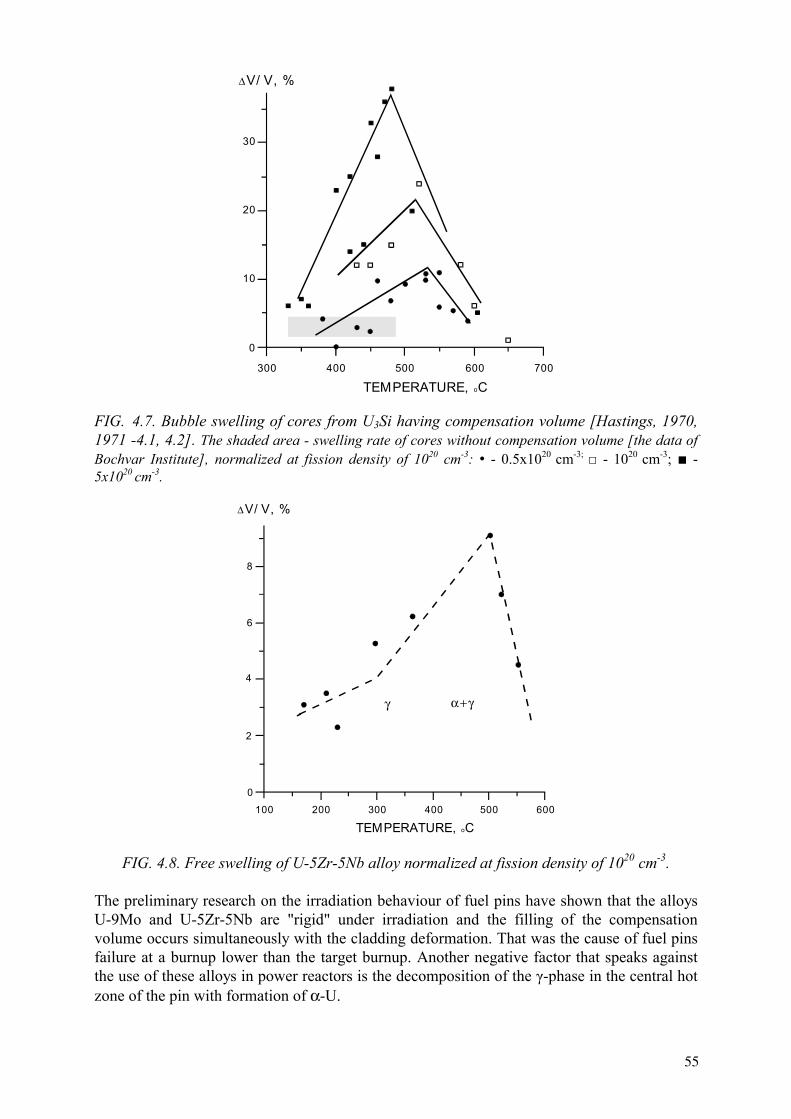
400 500 700600300
0
30
20
10
∆V/ V, %
TEMPERATURE, oC
FIG. 4.7. Bubble swelling of cores from U3Si having compensation volume [Hastings, 1970, 1971 -4.1, 4.2]. The shaded area - swelling rate of cores without compensation volume [the data of Bochvar Institute], normalized at fission density of 1020 cm-3: • - 0.5x1020 cm-3; - 1020 cm-3; - 5x1020 cm-3.
200 300 600400 500100
0
8
6
4
2
∆V/ V, %
TEMPERATURE, oC
γ α+γ
FIG. 4.8. Free swelling of U-5Zr-5Nb alloy normalized at fission density of 1020 cm-3.
The preliminary research on the irradiation behaviour of fuel pins have shown that the alloys U-9Mo and U-5Zr-5Nb are "rigid" under irradiation and the filling of the compensation volume occurs simultaneously with the cladding deformation. That was the cause of fuel pins failure at a burnup lower than the target burnup. Another negative factor that speaks against the use of these alloys in power reactors is the decomposition of the -phase in the central hot zone of the pin with formation of α-U.
55

The deformation of the Zr clad of the U3Si fuel rods only started after the gap and compensation volume closure. Taking into account this observation, the Russian R&D programmes concentrated just on this type of fuel. To prove the reliability of silicide fuel, experimental fuel rods were manufactured for in-pile irradiation tests in the MR and AI reactors (some samples were also tested in the AM reactor). RBMK commercial materials (claddings and end fittings) and manufacturing methods (welding, etc.) were used to fabricate these rods. The rod cladding of 13.6 mm diameter was filled with silicide fuel with a free volume of 8 to 14 %. The free volume consisted of a central axial hole in the rod and of longitudinal and circular grooves on the outer part of the rod. The gap between cladding and pellet was filled with He or with an eutectic Al-Si alloy in the case of an axial hole as free volume. The length of the experimental fuel rods for the MR reactor was 1 m, and 3.5 m for the AI reactor and basically with the same design as the commercial fuel rods of the RBMK reactor. The testing conditions corresponded to those of the reactor RBMK-1500, or exceeded them.
About a total of 200 experimental fuel rods were tested. The maximum burnup achieved was 29.6 MWd/kg U, which is quite higher than the nominal fuel discharge burnup in RBMK reactors (15–18 MWd/kg U). The average increase of the cladding diameter at such burnup was 0.55 mm. The gas release at about 20 MWd/kg U burnup was approximately 7%, at higher burnup it increased up to 15%.
In Canada [4.1, 4.2], the studies of the irradiation behavior of silicide fuel were carried out on fuel rod samples of ~ 15 cm length and a cladding diameter of 15.2 mm, and also on samples of about 50 cm length with cladding diameter of 13.7 mm. In total, some tens of fuel rod mock-ups were tested. The maximum fuel burnup was 16–20 MWd/kg U. The results obtained for the fuel rods tested in Russia and Canada showed a fair agreement. The cladding diameter increase varies nearly linearly with burnup (see Fig. 4.9).
Several experimental fuel rods of the MR type leaked during tests at burnups in the range of 13–20 MWd/kg U. They were used for studying the corrosion behavior of leaked fuel rods, and after the failure were further irradiated for another 10–15 days. From this experiment it was concluded that the leaching rate from the fuel rods ranged from 0.5 to 8 g per day at coolant temperatures ranging from 220 to 270oC. Because of hydride formation due to the fuel corrosion, radial cracks appeared, and water reached the central hot zone of the fuel. The outer part of the fuel remained undisturbed, while its central part was strongly corroded and destroyed (see Fig. 4.10).
Similar results on the behavior of leaked rods with silicide fuel were obtained in Canada.
According to the research carried out in the VNIINM by A.A. Bochvar, the cause for cladding failure can be attributed to the occurrence of cracks in the fuel, which in turn initiate the hydride formation in Zr cladding causing finally the clad breach. When an intermediate metal layer between cladding and core was used, this phenomenon was not observed.
In conclusion, the Russian R&D programmes on silicide fuel have demonstrated the possibility to achieve economically acceptable burnup level in the RBMK reactors loaded with this fuel. The technology and fuel pin design, practically excluding any failure possibility, has been successfully developed.
56

10 20 300
0
3
2
1
∆D/ D, %
BURNUP, MWd/kgFIG. 4.9 Change of fuel element diameter with cores from U3Si:
Light gray color - initial free volume in fuel element 13–17%; Dark gray - absence of compensation volume in the core.
FIG. 4.10. Fragment of cross-section of RBMK type fuel element with U3Si core after 12 days of operation in leaked condition, burnup of 20 MWd/kg U.
The programme on silicide fuel in Russia was frozen at the stage of the startup of a commercial fuel production facility with 5 t/a capacity and of performance tests on full-scale assemblies in an operating RBMK reactor. The reason for the cancellation of the Russian programme on metallic fuel was discontinuation of investments in new RBMK reactors and the uncertain status of the AST heat production reactors.
4.2. METMET fuels
The term "METMET fuel" means a dispersion of a METallic fuel in a METallic matrix. The behavior of uranium alloys under dispersion condition strongly differs from that of the bulk fuel as proved by the experience gained with these fuels operated at industrial scale. In the 1950s, Russia developed a dispersed fuel consisting of a U-9Mo alloy in Mg matrix. This type of fuel is used up to now in the Bilibinskaya NPP. The reactor types using such a fuel are mentioned in Table 4.3.
57

Table 4.3. Reactors with the fuel from U-9Mo alloy dispersed in Mg matrix
Parameter 1-st NPP, Obninsk
The 1-st block ofBeloyarskaya NPP
The 2-nd block ofBeloyarskaya NPP
Bilibinskaya NPP
Thermal power, MW
Output temperature of water coolant, oC
Height of reactor core, m
Enrichment of fuel, %
Burnup, MWd/kg U
Campaign, years
5
300
1.7
5
10
2
100
330(steam)
6.0
1.8
8
5
200
320(steam)
6.0
3.0
12
3
62 x 4
280(steam)
3.0
3.0, 3.3
18
2.5
METMET fuels are the precursors of the so-called "cold" fuels, and a better knowledge of their behaviour might lead to modifications of the classical design of power reactors. In Russia, R&D programmes on METMET fuels with Al and Zr as matrix materials have been decided in the 1990s and are now in progress.
The positive aspect of the use of dispersed fuels is associated with a significant improvement of the corrosion behaviour of the uranium alloys. The improvement of the corrosion resistance is influenced by two parameters: the protective properties of the matrix and the electrochemical passivation of the fuel particles. Some experimental data gained at VNIINM by A.A. Bochvar from out-of-pile testing using a zirconium matrix are collected in Table 4.4 [4.4].
In dispersed fuels the influence of the restrain due to the matrix has a paramount role on the fuel particle’s swelling. The level of influence depends on the mechanical properties of the matrix, the design of the fuel pin, the cladding properties and other factors. The experimental data [4.4] confirm the obvious restrain influence of the matrix on the swelling of the uranium alloys; some results are indicated in Tab. 4.5.
The interaction of the fuel with the matrix material could be a limiting factor for this concept. According to the preliminary data obtained on Zr and Mg matrices, this mechanism will not be determining for the irradiation stability of the fuel rod. Experimental results indicate that the threshold temperature of a technically significant interaction between pure U and Al is ~ 300oC, and for alloys is even much higher.
The cross-sections of some dispersion fuel variants after irradiation are shown in Figs 4.11–4.13.
58

Table 4.4. Comparison of corrosion rate in water of uranium alloys in bulk and dispersed forms
The characteristics of Samples
Temperature (oC)
Time (h)
Corrosion rate (mg/cm2h)
U-5Zr-5Nb
62 vol. % U-5Zr-5Nb + 37 vol. % Zr
360
360
30010003001000
0.340.580.0220.018
U3Si
65 vol. %U3Si + 35 vol% Zr
300
300
3009003001000
0.56destruction0.00460.0052
Table 4.5. Uranium alloys swelling in bulk and dispersion forms
Fuel Irradiation conditions Swelling composition (wt%)
Fuel type
Average temperature (oC)
Burnup of alloy (g U/cm3)
rate of alloy (% per 1g U/cm3)
U-5Zr-5Nb Bulk rod 180–220 0.28 63
Dispersed in Al matrix
150 1.8 ~30
U-5Zr-5Nb Bulk rod 240–280 0.26 150
Dispersed in Zr matrix 260 0.8 ≤15
U3Si Bulk rod
Dispersed in Zr matrix
240–290
250
0.26
0.65
90
≤15
U3Si Bulk rod
Dispersed in Al matrix
180–220
150
0.26
2.9
20
13
U-10Mo Bulk rod 300–400 0.2–0.4 21–43
U-9Mo Dispersed in Mg matrix
300–360 0.3 ≤20
59

FIG. 4.11. Structure of dispersion fuel element with U-5Zr-5Nb alloy in zirconium alloy matrix after irradiation. Burnup of fuel phase - 0.8 g U/cm3.
FIG. 4.12. Structure of dispersion fuel element with U3Si in zirconium alloy matrix after irradiation. Burnup of fuel phase - 0.65 g U/cm3.
FIG. 4.13. Structure of tubular fuel element for BAES with U-9Mo alloy dispersed in Mg matrix. External diameter — 20 mm.
The technology of METMET fuel (except of Mg+U-9Mo) was developed in the VNIINM by A.A. Bochvar only at an experimental scale. The usual fabrication route was the impregnation of molten matrix material in cladding filled by fuel particles. To obtain high particle loading (up to 70 vol.%), various size fractions were used. Filling of cladding was made by vibro-compaction. In order to fix the γ-phase in U-Mo and U-5Zr-5Nb alloys, they were transformed into fine particles by atomization. After impregnation, a controlled cooling of the fuel rods was used.
60

As a basic matrix material for LWRs, the eutectic Zr alloy with a melting temperature of about 850oC was selected. The main reason was to maintain the fuel swelling at a minimum level (level of solid swelling which is about 15 vol.% per 1 g U/cm3 burnup). Another reason for this choice was to avoid any interaction of the fuel with the matrix under irradiation. Some properties of advanced METMET fuels are shown in Table 4.6.
Table 4.6. Physical and neutronic characteristics of advanced METMET fuels for LWR (65 vol.% of fuel phase + 35 vol.% of Zr alloy matrix)
Parameter Fuel phase U3Si U-5Zr-5Nb U-9Mo U content in METMET, g/cm3 9.74 9.73 10.2
Thermal conductivity of METMET, W/(m·K) at 400oC
~ 25 ~ 25 ~ 23
Parasitic neutron capture cross sections, barn per one U atom
0.574 0.746 1.20
The use of METMET compositions might worsen the neutronics and consequently economic characteristics of LWR cores because of the parasitic capture of neutrons by alloying matrix elements, so that additional 235U is needed to compensate that. The use of a pure Zr matrix will allow reducing parasitic neutron capture approximately on 0.5 barn against the meanings given in Table 4.6. This measure allows to lower the U content in METMET by a factor of 1.3 comparing to the values given in Table 4.6 to the level of commercial UO2 fuel elements. The variant with pure Zr and extrusion production technology is presently under consideration in the VNIINM by A.A. Bochvar. In this case only the extrusion technology can be used with a maximum fuel particles content of 50 vol.%.
The above mentioned disadvantages of METMET compositions might be compensated by the high reliability of these fuel rods. A mechanical contact between the Zr cladding and the Zr matrix allows to achieve the radial deformation of Zr cladding of about 5% (instead of 2% for free standing fuel rod with UO2 fuel) and accommodate fuel swelling of 15 vol.%. Assuming a minimum swelling of fuel particles under restrained conditions of ~20% per 1 g U/cm3
burnup, an improvement by a factor of two can be reached in comparison to the values obtained in a LWR at similar burnup.
4.3. Uranium CERMET fuels of the type Al + UO2, Zr + UO2
The high thermal conductivity of the cermets fuels allows a reduction by a factor of two of the maximum fuel temperature with regard to that reached in a standard oxide fuel rod. The consequence of the use of CERMET fuels is of course a corresponding decrease of the energy stored in the reactor core.
Fuel rods with dispersed fuels have a high operational reliability at variable power regimes. This kind of fuel allows a large accumulation of fission products per fuel volume unit without prohibitive swelling. For example, at a burnup of 50 MWd/kg U in a WWER reactor there is an accumulation of 0.44 grams of fission products per cm3. In the case of fuel rods with dispersed fuel, achieving a fission products accumulation of (0.7–0.8) g/cm3 is possible, which permits an energy production of 80–90 MWd/kg U in the case of WWER fuel rods.
61
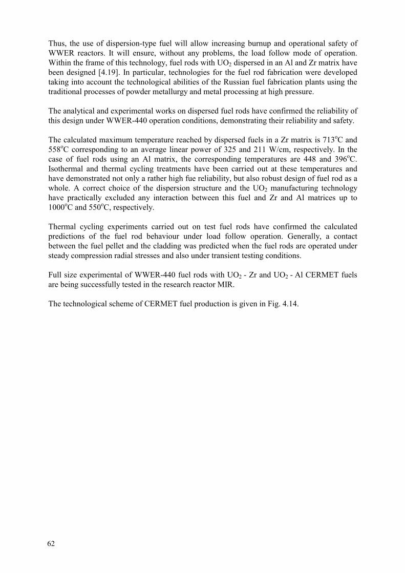
Thus, the use of dispersion-type fuel will allow increasing burnup and operational safety of WWER reactors. It will ensure, without any problems, the load follow mode of operation. Within the frame of this technology, fuel rods with UO2 dispersed in an Al and Zr matrix have been designed [4.19]. In particular, technologies for the fuel rod fabrication were developed taking into account the technological abilities of the Russian fuel fabrication plants using the traditional processes of powder metallurgy and metal processing at high pressure.
The analytical and experimental works on dispersed fuel rods have confirmed the reliability of this design under WWER-440 operation conditions, demonstrating their reliability and safety.
The calculated maximum temperature reached by dispersed fuels in a Zr matrix is 713oC and 558oC corresponding to an average linear power of 325 and 211 W/cm, respectively. In the case of fuel rods using an Al matrix, the corresponding temperatures are 448 and 396oC.Isothermal and thermal cycling treatments have been carried out at these temperatures and have demonstrated not only a rather high fue reliability, but also robust design of fuel rod as a whole. A correct choice of the dispersion structure and the UO2 manufacturing technology have practically excluded any interaction between this fuel and Zr and Al matrices up to 1000oC and 550oC, respectively.
Thermal cycling experiments carried out on test fuel rods have confirmed the calculated predictions of the fuel rod behaviour under load follow operation. Generally, a contact between the fuel pellet and the cladding was predicted when the fuel rods are operated under steady compression radial stresses and also under transient testing conditions.
Full size experimental of WWER-440 fuel rods with UO2 - Zr and UO2 - Al CERMET fuels are being successfully tested in the research reactor MIR.
The technological scheme of CERMET fuel production is given in Fig. 4.14.
62

Zr powderAl powder
plasticiser
Sintering
Hot calibration Cold calibration
Al barrel Zr & Cu barrels
Assembling of fuel blankin Al barrel
Assembling of fuel blankin Zr and Cu barrels
Extrusion of cermet core blanksin false cladding
Extrusion of cermet core blanksin false cladding
Assembling and jont rollingwith Zr tube
Assembling and jont rollingwith Zr tube
Quality control Quality control
Zr cladding tube
Assembling with plugsand sealing of faces
Assembling with plugsand sealing of faces
Cold pressing and degassing Cold pressing and degassing
Preparation of the blend Preparation of the blend
UO2 powderUO2 powder
FIG. 4.14. Technological flowchart of CERMET fuel element manufacturing on the basis of UO2 - Al and UO2 - Zr compositions.
REFERENCES TO CHAPTER 4
[4.1] HASTINGS, I,J., STOUTE, R.L., J. Nucl. Mater. 37/3 (1970) 295. [4.2] HASTINGS, I,J., J. Nucl. Mater. 41/2 (1971) 195. [4.3] PETROV, Yu.I., BASHLIKOV, S.N., MOROZOV, A.V., Uranium Silicides as
Nuclear Fuel, Energoatomizdat, Moscow (1984) (in Russian).
63
[4.4] KONOVALOV, I.I., Survey on metal fuel on a base of uranium alloys, Studies on Fuels with Low Fission Gas Release, IAEA-TECDOC-970, Vienna (1997) 183.
[4.5] KONOVALOV, I.I., VATULIN, A.V., “The Outlook of metallic Fuels for Different Types of Nuclear Reactors”, New Fuel Technology - Toward 21st Century (Proc. 2nd
Int. Seminar Taejon, 1997), KAERI (1998) 123. [4.6] KONOVALOV, I.I., PETROV, Yu.I., in Metals 6 (1993) 200 (in Russian). [4.7] Patent of Canada, 885 927, 1969. [4.8] KONOVALOV, I.I., in Special Questions in Atomic Science and Technique,
VNIINM, Moscow 1/56 (1998) 5. [4.9] LEGETT, R.A., et al., Report BNWL-SA-154, USA (1965). [4.10] LEGETT, R.A., BIERLAIN, T., MASTEL, B., Report HW-79559, USA (1963). [4.11] BELLAMY, R.G., BOURNE, L., UK Patent, N 1017540. [4.12] BELLAMY, R.G., BOURNE, L., UK Patent, N 1017981. [4.13] LEHMANN, J., BLANCHARD, P., in Bulletin d’Inf. Sc. & Techn. 48 (1970) 13. [4.14] HUDSON, in J. Nucl. Mat. 22 (1970) 121. [4.15] BLEIBERG, M.J., EICHENBERG, J.D., FILLNOW, R.H., Report WAPD-127, Part
IV, USA (1957). [4.16] SERGEEV, G.Ya., TITOVA, V.V., BORISOV, K.A., Metallurgy of Uranium and
Some Reactor Materials, Atomizdat, Moscow (1960) 142 (in Russian). [4.17] SHOUDY, A.A., in Proc. Venice Conf., vol 3, p. 133. [4.18] GOMOZOV, L.I., New Metallurgical Processes and Materials, Nauka, Moscow (1991)
194.[4.19] VATULIN, A.V., KONOVALOV, I.I., “Powder Metallurgy and Fabrication Processes
of Cermet and METMET Fuels in Russia”, Advances in Powder Materials Processing, Powder Metallurgy Association of India, vol. 26, Hyderabad (1999) 32–39.
64

CHAPTER 5
METAL AND DISPERSED FUELS FOR SMALL SIZE NUCLEAR REACTORS
5.1. Metallic fuels
The introduction of small size nuclear reactors (SSRs), which power is lower than 100 MW(t), started at the end of the 1950s with the construction of the first propulsion nuclear reactors for the Russian icebreaker "Lenin" and the US cargo boat "Savannah".
Several projects within the framework of the programme on small size nuclear reactors were developed in Russia in the 1980s and 1990s. One of them, the so-called "Barge mounted reactor", with a design similar that of the nuclear icebreaker reactor KLT-40S, is proposed for commercial realization. Such nuclear reactors must be economically competitive with conventional power installations loaded with organic fuel. Furthermore, these small size nuclear reactors have to operate in manoeuvre power mode depending on electricity demand. These facts, and the impossibility to quickly discharge failed fuel elements, impose very tough requirements on the fuel reliability. Therefore, the use of UO2 fuel rods cannot be considered.
In the beginning, the ship propulsion reactors were fuelled with Al-U alloys dispersed fuel of the type UAlx in an Al matrix (like the fuel for research reactors). The uranium content was very small — about 1 to 1. 5 g U/cm3. These fuels swelled under irradiation with minimum admissible rate — approximately at the level of the solid swelling, but compatibility problems arose due to fuel corrosion in the water coolant in case of fuel rod leakage.
This situation lead to the development of another type of metallic uranium alloys with improved water corrosion resistance [5.1]. Some design and performance data of alternatives to the Al-U alloy fuel are given in Table 5.1.
The alloys U-60 wt% Al and U-80 wt% Zr were selected because of their ability to create so called “metallurgical dispersion” structure by subsequent heat-mechanical treatment. The first alloy presents precipitates of the UAl3 phase dispersed in Al matrix, and the second alloy — the δ-U in a Zr matrix. The alloy U-80Zr gradually transforms under irradiation to the γ-phaseas a consequence of irradiation-induced homogenization and fuel alloying by fission products (mainly Mo and noble group metals) stabilizing the γ-U phase. According to basic thermodynamic data, another alloy U-50 wt% Zr - 10 wt% Nb should have the composition of α-Zr + δ + γ-U at temperatures below 500oC [5.3]. But this structure cannot be produced by long term annealing up to 2000 h at temperatures below 500oC. The γ-phase is stable under irradiation; the only structural transformation was the Zr carbide formation at temperatures above 400oC. Without irradiation the homogeneous γ-structure determines a very high corrosion resistance of U-50Zr-10Nb alloy in water environment, at the same level as that of unalloyed Zr. Irradiation behavior of U-80Zr and U-50Zr-10Nb are summarized in Figs 5.1–5.3.
The swelling of U-80Zr and U-50Zr-10Nb alloys at temperatures ~ 400oC is approximately two — three times higher than minimum theoretical solid swelling and is caused by bubbles formation (see Fig. 5.3). This swelling level is lower than that of uranium-rich alloys discussed in section 4.1, but is, nevertheless, still too high. Extremely high fuel discharge burnup (about 1g U/cm3), what is twice higher than that of the commercial NPP, is typical for small size nuclear reactors. The swelling of metallic fuel at the end of operation is about 40%
65

(see Fig. 5.1), and specific measures were undertaken to allow a compensation of the fuel swelling.
TABLE 5.1. Design and performance data of some metal fuels
Alloy Properties U-60 Al U-80Zr U-50Zr-10Nb
Density, g/cm3 3.8 7.8 9.1
Uranium content, gU/cm3 1.5 1.6 3.6
Achievable burnup (0.7 from all U atoms), g U/cm3: HEU (90% U-235) LEU (20% U-235)
0.90.21
1.00.22
2.30.50
Parasitic capture of neutrons by alloying elements, barn per one U atom.
3.1 2.1 1.4
Corrosion rate in water, mg/(cm2h) at: 300 oC 350 oC 400 oC (steam, 30MPa)
Destr. after 100 h 0.00070.0080.01
stable0.0020.005
0.2 0.4 0.6 0.8 1.00
30
20
10
0
∆V/ V, %
BURNUP, gU/ cm3
FIG. 5.1. Swelling of core of U-80Zr (light-grey area) and U-50Zr-10Nb (dark grey area) alloys at conditions of small power nuclear installations – average core temperature (350–450) oC. Dotted line — theoretical solid swelling.
66

4 0 0 6 0 0 8 0 0 1 0 0 02 0 0
2 0 0
1 5 0
1 0 0
5 0
0
∆ V / V , %o n b u r n a p o f 0 ,5 g U / c m 3
T EM P ER A T U R E , o C
FIG. 5.2. Unrestrained swelling of U-50Zr-10Nb alloy (for 0.5 gU/cm3 burnup).
FIG. 5.3. Structure of U-80Zr alloy after irradiation to 0.7 g U/cm3 burnup .
Apart from swelling, another problem linked to irradiation was the hydrogenation of fuel in case of cladding failure. That process, not observed in out-of-pile conditions, was caused by the simultaneous detrimental action of the temperature and stress fields in the irradiated fuel associated to the water hydrolysis. The formation of radial oriented hydrides in the fuel resulted in radial cracking allowing the access of water to the hot central part of the fuel. This process was not so intensive as in the case of high uranium content alloys, but the final result was the same as shown in Fig. 4.10. The low uranium density was another reason to reject metallic alloys for the LEU option (see Table 5.1). Therefore, several fuel options with high uranium density are now under investigation in Russia (see Section 5.2).
5.2. Metallic matrix associated to high density fuel and porosity
New concepts adapted to the new generation of SSRs are presently investigated in the VNIINM by A.A. Bochvar. Their characteristics are given hereafter. Their characteristics are given below:
V/V, % normalized at burnup of 0.5 gU/cm3
67

Type of fuel element Rod Coolant temperature 280–320oC Nominal lifetime 25 000 h
Maximum burnup 0.9 g U/cm3
Maximum thermal flow 1.5·106 MW(t)/m2
These fuel rods are designed to operate at thermal fluxes 1.5 times and burnups 2 times higher than those of commercial NPP with UO2 fuel. Alternatives, such as dispersed fuel consisting of high density uranium alloys and Zr and its alloys as matrix materials, are considered. Some design and performance data of the envisaged fuels are collected in Table 5.3.
Table 5.3. Some design and performance data of advanced fuel rods for SSRs [5.4]
Design and performance parameters
U-2Mo-1Si U-9Mo U3Si
Volumetric content of fuel alloy, %/100 Volumetric content of porosity, %/100
0.6
0.18
0.65
0.15
0.6
0.18
Uranium content in composition, gU/cm3
11.1 10.2 9
Achievable burnup, g U/cm3 forLEU (20% 235U)
1.55 1.43 1.26
Parasitic capture cross section by alloying elements, barn per one U atom
0.45 0.98 0.34
Thermal conductivity at 400 oC,Wt/(m·K)
18.0 19.2 17.5
The following technological fuel production alternatives are considered:
• Pressing and sintering of powders in cylindrical pellets with further calibration or extrusion;
• Filling of the cladding by fuel granulates and impregnation of the Zr alloy matrix.
Both technologies result in pellet porosity of the matrix sufficient for swelling compensation (up to 15–17 vol.%).
The second manufacturing route is the following: filling of the cladding by fuel and matrix alloy particles, and subsequent heating. By heating the mixture, the matrix alloy melts and impregnates the fuel particles inside the cladding. Through this process, a definite amount of porosity is formed in the matrix, thus creating a potential accommodation volume for fuel swelling as illustrated in Fig. 5.4. This figure shows the microstructure of a dispersed fuel with the following composition (in vol.%): uranium alloy - 62, matrix - 20, compensation volume - 18. Considering an estimated swelling rate of the uranium alloy of 30% per 1 g U/cm3 burnup, the cladding deformation of the fuel rod will be less than 3% at the targeted
68

burnup. The dispersed fuels having the envisaged compositions were produced at laboratory scale, and their properties were studied. Alloys with the following compositions were obtained (wt%): U-5Zr-5Nb, U-9Mo, U-2Mo-1Si and U3Si. The uranium density in dispersion fuel compositions is 8.9 to 10.1 g/cm3. A rather high thermal conductivity for the dispersed fuels of 19.2 W/m2K at 400oC, and a good contact between fuel and cladding ensure low fuel operation temperatures (never above 550oC).
FIG. 5.4. Structure of dispersion fuel element with U-9Mo alloy and porous Zr alloy matrix.
At present time, out-of-pile investigations are carried out including: compatibility studies of the fuel and matrix components, corrosion resistance testing of the cladding and dispersed fuel, analysis of various dispersion compositions, computer modeling, and obtaining further necessary data to confirm serviceability of the fuel rods.
REFERENCES TO CHAPTER 5
[5.1] KONOVALOV, I.I., VATULIN, A.V., “The Outlook of metallic fuels for different types of nuclear reactors”, New Fuel Technology - Toward 21st Century, KAERI (1998) 123.
[5.2] GOMOZOV, L.I., IVANOV, O.S., Corrosion resistance of some uranium alloys in “Structure and Properties of Uranium, Thorium and Zirconium Alloys”, Moscow, Gosatomizdat (1963) 175 (in Russian).
[5.3] IVANOV, O.S., GOMOZOV, L.I., U-Zr-Nb phase diagrams in “Structure and Properties of Uranium, Thorium and Zirconium Alloys”, Moscow, Gosatomizdat (1963) 107 (in Russian).
[5.4] Report “Project ISTC “Development of new generation fuel for WWERs”, VNIINM, Moscow, No 173-95.
69

CHAPTER 6
HIGH DENSITY FUELS FOR RESEARCH REACTORS
6.1. Introduction
Within the framework of the international reduced enrichment for research and test reactors (RERTR) programme studies on low enrichment fuels are carried out all over the world as substitution candidates of the current fuels used for research reactors. The RERTR programme was established in 1978 at the Argonne National Laboratory (ANL) with primary objective to develop the technology needed to use low enriched uranium based fuel (LEU) instead of high enriched uranium based fuel (HEU). At present time, ANL continues co-ordination and leading effort in the RERTR programme. In this context there was a need of developing a fuel with a higher density than that of the currently used highly enriched UO2 /UAlx/UzrHx/U3Si2compounds. Various types of compounds with very high uranium density have been considered. We have to mention UN-Al (CERCA/France-ITU/Germany [6.1], VNIINM/Russia [6.2]), and the metal-based U-Zr-Nb or U-Mo alloys (France, Japan, Korea, Rep. of, the Russian Federation, USA, and others). The highest priority has been given to U-Mo alloys. A recent status of the fuel related activities performed within the framework of the RERTR programme was reported by fuel experts from France [6.3], Japan [6.4], Korea, Rep. of, (KAERI jointly with the ANL) - [6.5]), the Russian Federation [6.2] and the USA [6.6] at the 22nd RERTR International Meeting held in Budapest in October 1999.
6.2. CERMET fuels
A survey of the mononitride fuel development jointly performed between 1985 and 1994 by the CERCA and the European Institute for Transuranium Elements (ITU) can be found in Ref. [6.1]. CERCA and ITU put their knowledge and experience together in an exploratory programme in order to test, at a laboratory scale, the manufacture of MTR plates combining the advanced process of CERCA (allowing a high fuel volume fraction) and the use of uranium nitride fuel (containing a high weight percentage of uranium). Using this method, plates with a very high uranium density of around 7 g U/cm3 can be expected.
In Russia and in other countries, the uranium silicides with a density not lower than 12 g U/cm3 were chosen as the most acceptable alternative. All necessary R&D steps, including manufacturing technology, scrap reprocessing, and irradiation tests were performed. Unfortunately, some difficulties arose in the commercialization of these fuels and their production and supply were cancelled
Research focusing on the uranium nitride (UN) with about 14 g U/cm3 density was carried out in parallel at VNIINM by A.A. Bochvar in the Russian Federation. Uranium nitride is attractive due to its easy production as powder granules. The fabrication process is simple (see Fig. 6.1) and inexpensive. The basic manufacture process stages include:
• Uranium hydriding • Uranium nitriding • Decomposition of “one and half” nitride • Pressing and sintering of briquettes • Crushing and separation on necessary fractions.
71

1- Loading chamber 6 - Electric furnace 2,3 - Installation for hydrating of metal uranium 7 - Unloaded chamber 4 - Feeder 8 - Receiving can 5 - Installation for nitrating 9 - Electric drive
FIG. 6.1. The basic equipment and technological stages of UN production.
The technological flow scheme for UN-Al fuel element fabrication is also straightforward and includes the following stages:
• Dry blending of UN granules and Al powder • Blending with plasticeser • Cold pressing, degassing and sintering • Hot sizing and QC • Assembling • Extrusion, machining and QC
Thermodynamic calculations and experiments (out-of-pile annealings) have confirmed the high stability of UN-Al and UN-Zr compounds (Fig. 6.2–6.3). UN-Al has high thermodynamic stability at temperatures up to 500 oC, and UN-Zr — at temperatures up to 800 oC. At temperatures exceeding these ones, interaction of the fuel component UN with matrix (Al or Zr) starts with formation of UAl3 and UAl4 and UZr2 and ZrN, respectively (Fig. 6.2). These phase transformations are accompanied by swelling (Fig. 6.3). Out-of-pile investigations demonstrated that the compounds UN-Al and UN-Zr can be considered as candidates for CERMET fuels for the use in research reactors.
6.3. METMET fuels
As mentioned in Paragraph 6.1, non-proliferation considerations constitute the main driving force for designing uranium metallic fuels for research reactors, the major requirement being fuel enrichments not exceeding 20% (RERTR programme, [6.2–6.6]).
72

FIG. 6.2. Thickness of the interaction layer (h, mm) between fuel and matrix components as a function of the annealing temperature (annealing time-4 hours) for UN-Al (left) and UN-Zr(right).
FIG. 6.3. Fuel composition swelling as a function of the annealing temperature (annealing time-4 hours) for UN-Al (left) and UN-Zr right).
Consequently, the research reactor fuels were stepwise substituted by higher uranium density fuels with various chemical composition ranging from Al-U alloys and UAlx dispersed in Al (~1.5 g U/cm3) to UO2 and U3Si2 dispersed in Al (up to 4 g U/cm3). Finally, very-high density fuels were envisaged and studied (up to 9 g/cm3).
The increase of uranium density to 8 g U/cm3 will meet the operating and safety requirements of some high power research reactors.
In the 1980s, Russian experts have studied the irradiation behaviour of high density uranium alloys of the type U3Si and U-5Zr-5Nb dispersed in an Al matrix [6.7]. As the uranium alloys
73

before were not used inside an Al matrix, the main problem was the high chemical reactivity of the metals (U and Al) and the possibility of a significant interaction of these elements during the fabrication and under irradiation. A decrease of this interaction during production process (sintering of mixed powder pellets) was absolutely necessary, and special fuel particle passivation methods were developed.
The irradiation experiments demonstrated the possibility of using metal uranium alloys in dispersed type fuels for research reactors. The interaction of U3Si and U-5Zr-5Nb alloys with the Al matrix was insignificant. The rim around the fuel particle was 15 microns, corresponding to a recoil effect.
The next stage was the thorough investigation of different U alloys as fuels for research reactors. Very intensive research is presently being conducted in the USA (ANL) [6.2]. The composition and some properties of the various fuels considered are presented in Table 6.1.
Table 6.1. Categories of metal fuels with very high density
Fuel composition Classification Density, g/cm3 U content (45 vol.% of fuel), g/cm3
Maximal burnup for LEU fuel (0.7 from U-235 atoms), x1021 cm-3
U+(8-10) Mo Most stable γphase
17.6 7.2 2.6
U+(4-6) Mo U+(8-12) Zr+Nb
Intermediate γstability
18.216.7
7.86.8
2.82.4
U-(1-2) Mo α′ -phase 18.6 8.3 (8.0*) 2.9*Note: * - calculated values taking into account the protective film on fuel particles.
Three technological processes were used to produce the fuel particles. The first one is the atomization process characterized by the spraying of molten alloy onto a rotating disk. The second one is the press crushing of castings, and the third one is the mashing of fuel rods with subsequent scraping by milling. The production of dispersed fuels is made conventionally by using the well-known fabrication process of CERMET fuel.
In the USA during the last years, sixty-four microplates, mainly composed of intermediate γ-stable alloys (see Tab.6.1) have been irradiated to approximately 40% and 70% 235U burnup in the advanced test reactor (ATR). The post-irradiation examination of these microplates is under way. The preliminary results of METMET testing are promising. In general, the experimental results indicated better performance of the U-Mo alloys, as compared to the U-Zr-Nb alloys.
REFERNCES TO CHAPTER 6
[6.1] DURAND, J.P., LAUDAMY, P., RICHTER, K., “Preliminary developments of MTR plates with uranium nitride”, RERTR, ANL 9700 South Cass Av. Argonne, Ill., ANL/RERTR/TM-20, CONF-9409107 (1997) 191.
[6.2] LAVRENIUK, P.I., CHERNYSHOV, V.M., et al, “The Russian RERTR Programme works status”, (in press).
74

[6.3] ROMANO, R., NIGON, J.-L., LANGUILLE, A., LE BORGNE, E., FRESLON, H., “The French development programme for a UMo fuel”, (in press).
[6.4] KAIEDA, K., BABA, O., NAGAOKA, Y., KANDA, K., NAKAGOME, Y., “Status of Reduced Enrichment programme for research reactors in Japan, (in press).
[6.5] MEYER, M.K., PARK J.M., KIM, K.H., et al “Irradiation behaviour of uranium-molybdenum dispersion fuel: fuel performance data from RERTR-1 and RERTR-2”, (in press).
[6.6] TRAVELLI, A., “Progress of the RERTR Programme in 1999”, (in press). [6.7] ADEN, V.G., KARTASHOV, E.F., STETSKY, Y.A., et al, “The current state of the
Russian Reduced Enrichment Research Reactor Programme”, see [6.1], p. 27.
75
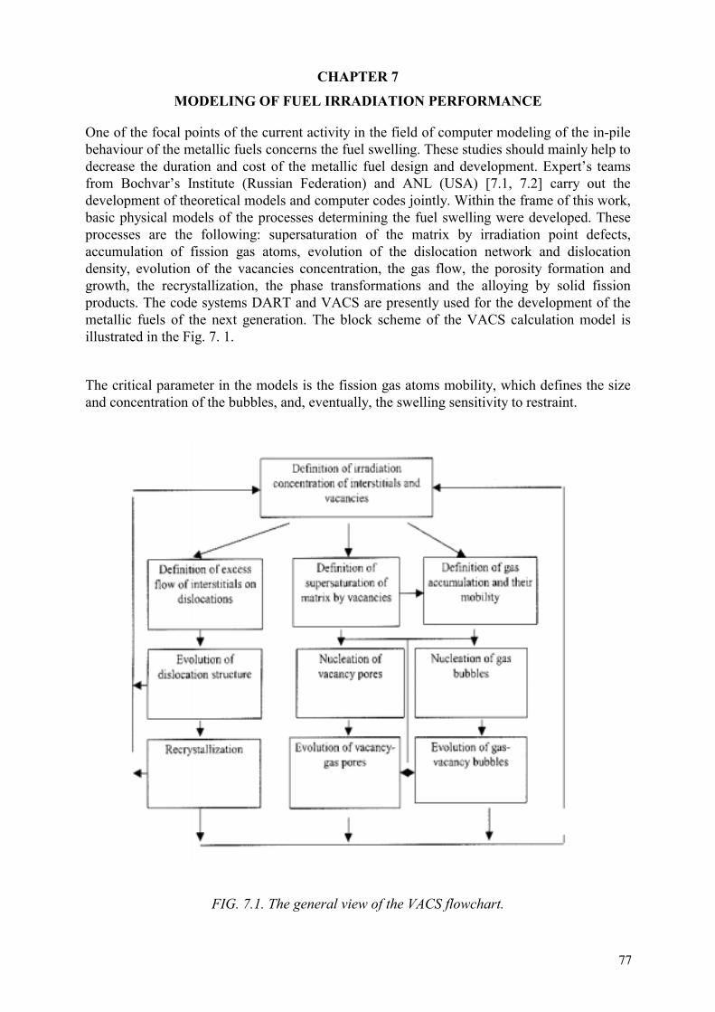
CHAPTER 7
MODELING OF FUEL IRRADIATION PERFORMANCE
One of the focal points of the current activity in the field of computer modeling of the in-pile behaviour of the metallic fuels concerns the fuel swelling. These studies should mainly help to decrease the duration and cost of the metallic fuel design and development. Expert’s teams from Bochvar’s Institute (Russian Federation) and ANL (USA) [7.1, 7.2] carry out the development of theoretical models and computer codes jointly. Within the frame of this work, basic physical models of the processes determining the fuel swelling were developed. These processes are the following: supersaturation of the matrix by irradiation point defects, accumulation of fission gas atoms, evolution of the dislocation network and dislocation density, evolution of the vacancies concentration, the gas flow, the porosity formation and growth, the recrystallization, the phase transformations and the alloying by solid fission products. The code systems DART and VACS are presently used for the development of the metallic fuels of the next generation. The block scheme of the VACS calculation model is illustrated in the Fig. 7. 1.
The critical parameter in the models is the fission gas atoms mobility, which defines the size and concentration of the bubbles, and, eventually, the swelling sensitivity to restraint.
FIG. 7.1. The general view of the VACS flowchart.
77
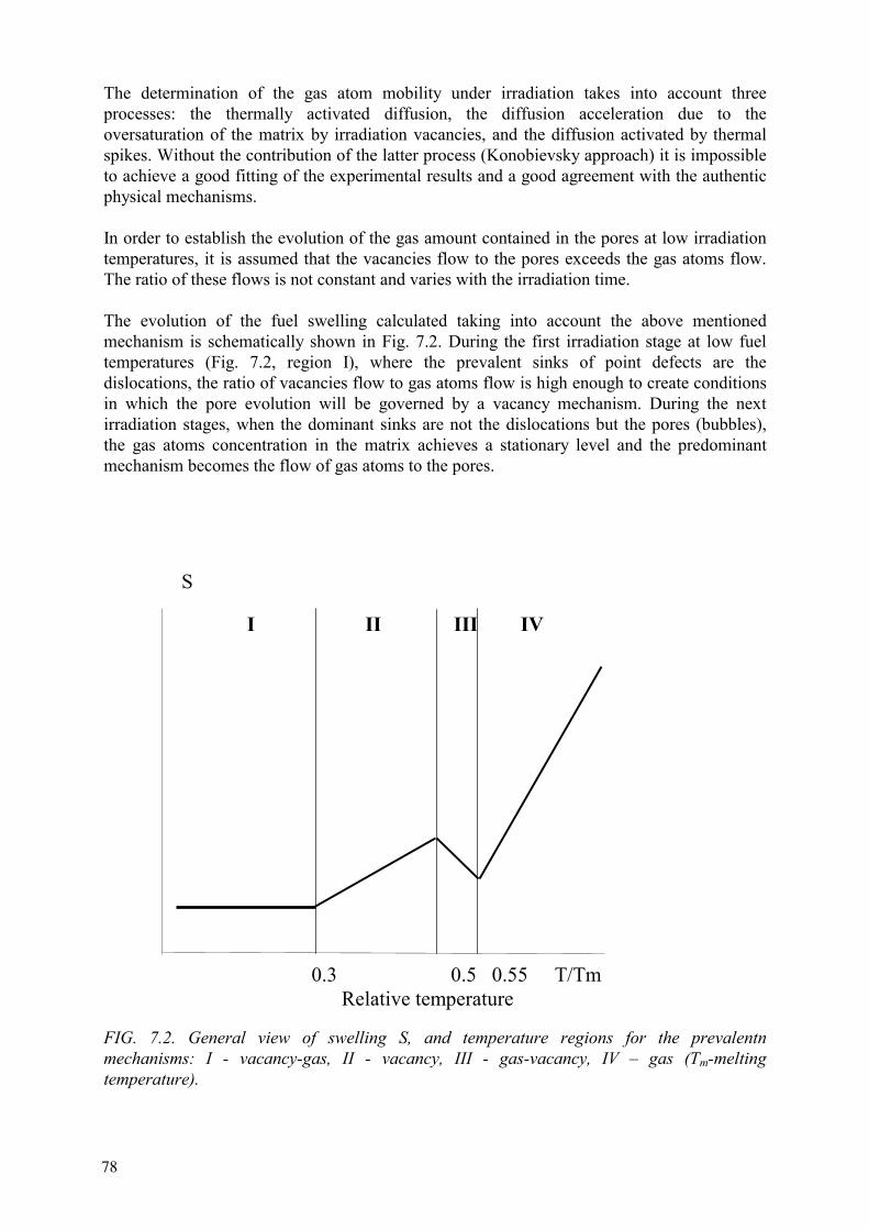
The determination of the gas atom mobility under irradiation takes into account three processes: the thermally activated diffusion, the diffusion acceleration due to the oversaturation of the matrix by irradiation vacancies, and the diffusion activated by thermal spikes. Without the contribution of the latter process (Konobievsky approach) it is impossible to achieve a good fitting of the experimental results and a good agreement with the authentic physical mechanisms.
In order to establish the evolution of the gas amount contained in the pores at low irradiation temperatures, it is assumed that the vacancies flow to the pores exceeds the gas atoms flow. The ratio of these flows is not constant and varies with the irradiation time.
The evolution of the fuel swelling calculated taking into account the above mentioned mechanism is schematically shown in Fig. 7.2. During the first irradiation stage at low fuel temperatures (Fig. 7.2, region I), where the prevalent sinks of point defects are the dislocations, the ratio of vacancies flow to gas atoms flow is high enough to create conditions in which the pore evolution will be governed by a vacancy mechanism. During the next irradiation stages, when the dominant sinks are not the dislocations but the pores (bubbles), the gas atoms concentration in the matrix achieves a stationary level and the predominant mechanism becomes the flow of gas atoms to the pores.
FIG. 7.2. General view of swelling S, and temperature regions for the prevalentn mechanisms: I - vacancy-gas, II - vacancy, III - gas-vacancy, IV – gas (Tm-melting temperature).
I II III IV
S
0.3 0.5 0.55 T/Tm Relative temperature
78

The latter situation, characterized simultaneously by a deficiency in vacancies and a higher gas atom supply to the pores, modifies the general equilibrium conditions of the porosity. It leads to a transition of an underpressurized bubble state created by a pure vacancy flow mechanism to an equilibrium gas bubble state governed by a vacancy-gas mechanism.
The time at which the transition occurs depends on two factors: firstly on the vacancy amount absorbed during the initial irradiation stage, and secondly on the pore growth rate by vacancy mechanism. The value of the vacancy amount absorbed is approximately proportional to the dislocation density. The estimated fission density for this transition is about 1021 cm-3. Thus at fission density values characteristic for research reactors (A~5⋅1021 cm-3), the fuel should not contain under-pressurized bubbles created by a vacancy mechanism, but gas bubbles at equilibrium pressure.
According to the calculations, it can be noticed that above a definite temperature the vacancy diffusion is thermally activated. In this case, the vacancies amount reaching the pores grows exponentially. The pores originally generated by a vacancy mechanism do not transform into gas bubbles. Basically, this temperature zone is characterized by a vacancy swelling mechanism (zone II) only.
The zone III, with a swelling rate decreasing as the fuel temperature increases, corresponds to a gas-vacancy mechanism. At these temperatures, the pores originally develop as equilibrium gas bubbles and thereafter grow by a vacancy mechanism.
At higher temperatures (zone IV), the concentration of irradiation point defects is negligible in comparison to the concentration of thermally created point defects. In this zone the pore is a stable bubble whose growth depends on a pure gas diffusion mechanism.
Numerical swelling estimations were carried out for various fuel types, according to their operation conditions in research reactors.
The main parameters determining swelling are the diffusion coefficients of vacancies and of gas atoms. However, at low irradiation temperatures the determining factor for vacancies and gas atoms diffusion is the Konobeevsky factor, which is associated with the activation due to the thermal spikes. Under these conditions, the swelling rate is nearly independent on the nature of the material. The only essential change is to be expected in the temperature range where the thermally activated diffusion exceeds the irradiation activated diffusion. Thus, the meaning of activation energy of diffusion is somewhat complex and must be used carefully.
According to the data given in the review [7.3], the experimental data relevant to diffusion in uranium and its alloys strongly differ from each other. For example, for α-U the values of activation energy for self-diffusion range from 1.1 to 2.5 eV, and a difference of a factor of two makes any correct and reliable calculations practically impossible. In this context, a uniform value has been selected for all materials. It is characterized by a vacancy formation energy Efv = 8.9⋅10-4Tm and migration energy Emv = 7.2⋅10-4Tm with the pre-exponential term equal to 0.01 cm2/s. For the peritectic compounds, the solidus temperature was considered as the melting temperature Tm. The parameters used for the calculations are given in Table 7.1.
79

Table 7.1. Calculated diffusion parameter values
Material Tm (K) Efv (eV) Emv (eV) UU6(Fe,Mn,Ni,Co) U3Si U-10 wt.%Mo, U-10 wt.%Nb UAl2, U3Si2UO2
140010701260152018703150
1.250.951.121.361.672.80
1.010.770.911.101.352.27
The swelling estimations were carried out using the VACS code, considering that the cluster composed of two Xe atoms has to be accepted as the smallest gas nucleus. As a further assumption, it was admitted that two Xe atoms in substitution should push each other because of the stress fields. Finally, it was assumed that for stabilizing a cluster, the presence of vacancies is necessary in such a way that the smallest gas nucleus is composed of 2Xe atoms+3 vacancies. The results of the calculations for the damage rate K = 10-3 dpa/s (displacements per atom per second) are given in Figs 7.3 and 7.4.
According to these numerical data, the fuel composition has a very weak influence on the swelling in the temperature range where the irradiation activation is greater than the thermal activation. The beginning of relevant swelling occurs at temperatures where the thermally activated diffusion component is predominant.
As already mentioned, the basic parameters used for the swelling computation are a function of temperature. In the temperature range with prevalent swelling mechanism given by the irradiation activation, the bubble density was about 10 17 cm-3, and the average bubble diameter about 10-6 cm. In the temperature range where the swelling increases as the fuel temperature increases and is governed by a thermally activated mechanism, the bubble density decreases with a simultaneous increase of their diameter. For uranium at 200oC and fission density 1.5⋅1021 cm-3, the calculated bubble density was 6.6⋅1015 cm-3, and the average bubble diameter 7⋅10-6 cm.
FIG. 7.3. Temperature dependence of unrestrained swelling S for various fuel types at 1021
cm-3 fission density and damage rate 10-3 dpa/s. The dotted line represents the theoretical "solid" swelling.
80
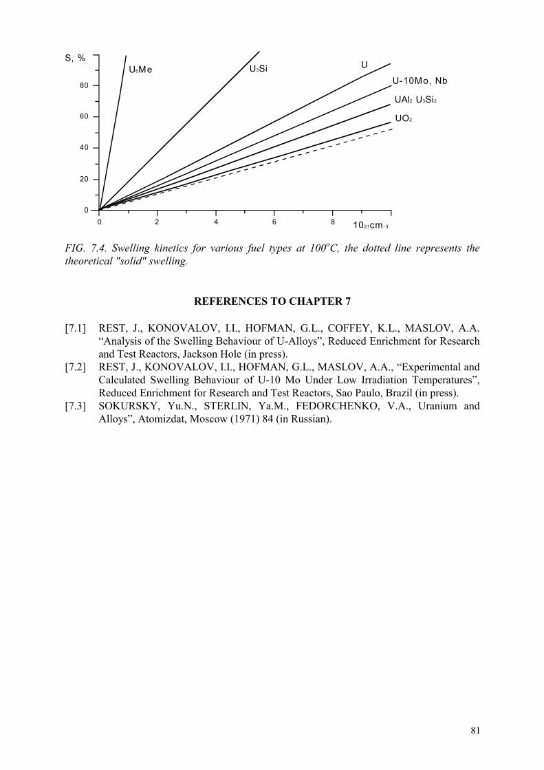
FIG. 7.4. Swelling kinetics for various fuel types at 100oC, the dotted line represents the theoretical "solid" swelling.
REFERENCES TO CHAPTER 7
[7.1] REST, J., KONOVALOV, I.I., HOFMAN, G.L., COFFEY, K.L., MASLOV, A.A. “Analysis of the Swelling Behaviour of U-Alloys”, Reduced Enrichment for Research and Test Reactors, Jackson Hole (in press).
[7.2] REST, J., KONOVALOV, I.I., HOFMAN, G.L., MASLOV, A.A., “Experimental and Calculated Swelling Behaviour of U-10 Mo Under Low Irradiation Temperatures”, Reduced Enrichment for Research and Test Reactors, Sao Paulo, Brazil (in press).
[7.3] SOKURSKY, Yu.N., STERLIN, Ya.M., FEDORCHENKO, V.A., Uranium and Alloys”, Atomizdat, Moscow (1971) 84 (in Russian).
2 4 6 8 1021cm-30
0
40
60
20
80
S, %U6Me U3Si
UO2
U
U-10Mo, Nb
UAl2 U3Si2
81

CHAPTER 8
FUEL FOR INCINERATION OF WEAPON AND REACTOR GRADE PLUTONIUM
The most efficient way to enhance the plutonium consumption in LWRs is to eliminate entirely plutonium production under irradiation. This requirement leads to fuel concept in which uranium is replaced by an inert matrix (diluent). For reactivity control reasons, adding a burnable absorber to this fuel proves to be necessary as shown in Refs [8.1 and 8.2]. For example, at Paul Scherrer Institute, studies have focused on employing ZrO2 as inert matrix stabilized by rare earth oxide for better radiation resistance, and on Er2O3 as burnable absorber material. X ray diffraction studies of a simulated fuel material (Zr0.95-x-yYxEr0.05My)O1.975-x/2with M=Ce, U or Th as analogue of Pu (x=0.10-0.15, y=0.07-0.10) have confirmed that this quaternary material forms a single solid solution [8.1].
Burning of fissile actinides in nuclear reactors requires inactive materials which act as act as diluents in the austenitic steel or Zr-based clad fuel pins in order to soften the high fission density and consequently, the high fuel temperature (“cold” fuel concept). At present, many variants of diluents are under consideration: homogeneous and heterogeneous diluents forming a solid solution with fissile material and a two-phase microstructure, respectively, ceramic and metallic diluents [8.3–8.8].
8.1. Ceramic diluents (CERCER)
PuN and PuO2 are considered in Refs [8.3–8.8] as plutonium containing materials taking into account their physical and chemical behavior. The basic properties of these compounds are given in Table 8.1
Table 8.1. Basic properties of PuN and PuO2 [8.8]
Property PuO2 PuNMelting point, oC
Total vapor pressure, bar 1500oC2000oC
Thermal conductivity W/Km 1000oC1500oC2000oC
Chemical behavior towards: austenetic steel liquid sodium waternitric acid at 110oC
2428
4.10-10
3.10-7
3.02.62.7
no reaction below 1000oCNa4Pu2O5 formation oxide hydride formation not dissolvable
Decomposition 2570, 1 bar N2
1.2.10-6
7.10-4
131415
No reaction below 600oCno reaction PuO2 formation dissolvable (also in HCl)
83

The selection of diluents is based on particular physical and chemical properties which determine the preparation, handling, thermal and irradiation stability, interaction with coolant and the dissolution behavior in acids during reprocessing.
Review of out-of-pile properties of different diluents for inert matrix fuel (IMF) is presented in Tables 8.2–8.5. The proposed compounds B4C, SiC, ZrSiO4, CePO4 and BN have specific features that make them useless as diluents. The pseudo-binary systems B4C and SiC with steel and SiC with Zircalloy are not in thermodynamic equilibrium. The strong reaction leading to formation of borides, carbides and silicides with Zr and Fe begins at 700oC. The phase ZrSiO4 decomposes eutectoidally at 1676oC into ZrO2 and SiO2. The phase CePO4 has very low thermal conductivity — less than 2 W/K·m. BN has high thermal conductivity (20–30) W/K·m, good chemical behavior, but very high total vapor pressure — 5.10-3 bar at 2000oC.
If compatibility of PuO2 with coolant, as the main precondition, has to be strictly fulfilled, this type of fuel would not be qualified for plutonium incineration in sodium cooled reactors. If this precondition is disregarded, the heterogeneous and homogeneous diluents Al2O3, MgO and MgAl2O4 as well as CeO2, Y2O3 and stabilized ZrO2 can be considered. PuN has better out-of pile properties as fuel than PuO2. Some perspective diluents for PuN are shown in Tables 8.4–8.5.
The analysis of the data in Tables 8.4, 8.5 demonstrates the excellent physical properties of AlN and ZrN. They are recommended as heterogeneous and homogeneous diluents, respectively, for PuN fuel. ZrN can be considered also as diluent for PuO2 fuel because these materials form a stable thermodynamic couple.
Table 8.2. Basic properties of homogeneous diluents for PuO2 [8.8]
Properties Diluents CeO2 Y2O3
* ZrO2
Melting temperature, oC 2400 2430 2710Total vapor pressure, bar 2.10-7 (1500oC) 2.10-7 (2000oC) 10-8 (2000oC) Thermal conductivity, W/K·m 500oC100015002000
1.20.91.2
4.12.52.9~4
2.21.51.8
Compatibility austenitic steel
liquid sodium waternitric acid
no reaction below 650oC
NaCeO2 formation no reaction
low rate of dissolut.
?
no reaction slowly dissolvable
low rate of dissolut.
no reaction below 1200oC (iron)
no reaction no reaction
not dissolvable Note *) - An extended solid solubility up to about 90 mol% Y2O3 at 1500oC
84

Table 8.3. Basic properties of heterogeneous diluents for PuO2 [8.8]
Properties Diluents Al2O3 MgO MgAl2O4
Melting temperature, oC 2054 2827 2105Total vapor pressure, bar ~10-6 (1950oC) 10-4 (1727oC) ?Thermal conductivity, W/K·m 500oC100015002000
13.38.25.8
201365
97.7~8
Compatibility austenitic steel
liquid sodium water
nitric acid
no reaction below 900oC (iron) no reaction no reaction (bulk material) not dissolvable
no reaction below 1100oC (iron) no reaction hydroxide formation
low rate of dissolut.
?
no reaction ?
?
Table 8.4. Basic properties of homogeneous diluents for PuN [8.8]
Properties Diluents CeN YN ZrN
Melting temperature, oC 2480 2670 2960Nitrogen vapour pressure, bar 1500oC2000oC
4.10-8
4.10-4 ~10-7
~10-3 10-12
10-7
Thermal conductivity, W/K·m 500oC100015002000
~ 5 (800–2000oC) ?17232624
Compatibility with austenitic steel
liquid sodium waternitric acid air
?
?decomposes dissolvable oxidation
?
??
dissolvable oxidation
formation of ZrM2Npossible
?no reaction dissolvable no oxidation
85
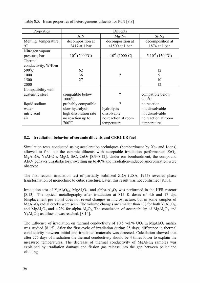
Table 8.5. Basic properties of heterogeneous diluents for PuN [8.8]
Properties Diluents AlN Mg3N2 Si3N4
Melting temperature, oC
decomposition at 2417 at 1 bar
decomposition at <1500 at 1 bar
decomposition at 1874 at 1 bar
Nitrogen vapour pressure, bar 10-3 (2000oC) ~10-8 (1000oC) 5.10-3 (1500oC) Thermal conductivity, W/K·m 500oC100015002000
623627
?129
1012
Compatibility with austenitic steel
liquid sodium waternitric acid air
compatible below 1000oCprobably compatible slow hydrolysis high dissolution rate no reaction up to 700oC
?
?hydrolysis dissolvable no reaction at room temperature
compatible below 900oCno reaction not dissolvable not dissolvable no reaction at room temperature
8.2. Irradiation behavior of ceramic diluents and CERCER fuel
Simulation tests conducted using acceleration techniques (bombardment by Xe- and I-ions) allowed to find out the ceramic diluents with acceptable irradiation performance: ZrO2,MgAl2O4, Y5Al5O12, MgO, SiC, CeO2 [8.9–8.12]. Under ion bombardment, the compound Al2O3 behaves unsatisfactory: swelling up to 40% and irradiation-induced amorphization were observed.
The first reactor irradiation test of partially stabilized ZrO2 (USA, 1955) revealed phase transformation of monoclinic to cubic structure. Later, this result was not confirmed [8.11].
Irradiation test of Y3Al5O12, MgAl2O4, and alpha-Al2O3 was performed in the HFR reactor [8.13]. The optical metallography after irradiation at 815 K doses of 4.6 and 17 dpa (displacement per atom) does not reveal changes in microstructure, but in some samples of MgAl2O4 radial cracks were seen. The volume changes are smaller than 1% for both Y3Al5O12and MgAl2O4 and 4.2% for alpha-Al2O3. The conclusion of acceptability of MgAl2O4 and Y3Al5O12 as diluents was reached. [8.14].
The influence of irradiation on thermal conductivity of 10.5 vol.% UO2 in MgAl2O4 matrix was studied [8.15]. After the first cycle of irradiation during 25 days, difference in thermal conductivity between initial and irradiated materials was detected. Calculation showed that after 275 days of irradiation the thermal conductivity should be 4 times lower to explain the measured temperatures. The decrease of thermal conductivity of MgAl2O4 samples was explained by irradiation damage and fission gas release into the gap between pellet and cladding.
86

JAERI (Japan) develops the rock-like oxide (ROX) plutonium fuels for their once-through burning in LWRs followed by direct disposal of spent fuel after cooling [8.16]. The ROX fuel is a multi-phase mixture of mineral-like (or rock-like) compounds such as stabilized zirconia, corundum, spinel an so on. Plutonium is incorporated into one of these compounds. Direct disposal of irradiated ROX fuels requires that the irradiated fuels must have high chemical, physical and geological stabilities to reduce environmental hazards. On the basis of low neutron capture cross sections and acceptable physico-chemical properties of minerals and ceramics, two systems, namely Y-stabilized ZrO2 (YSZ)-corundum (Al2O3)-spinel (MgAl2O4)and ThO2- corundum (Al2O3)-spinel (MgAl2O4) as candidates of the ROX matrices. PuO2 was added to the above mentioned compounds by oxide powder mixing, pellet pressing and sintering. Both fuel types were irradiated in JRR-3 reactor during 67 days at temperature from 980 to 1273 K. After irradiation the most of samples had cracks or were fragmented. Too high fission rate was mentioned as major cause for this phenomenon. It was concluded that addition of Al2O3 should be minimized, because of its high swelling rate, Pu-hibonite phase formation and lower melting point.
The irradiation of composite containing microspheres of UO2, MOX and PuO2 dispersed in MgAl2O4 matrix was done in reactors SILOE and OSIRIS. After irradiation, pellets were deformed, had cracks, or were destroyed. The reason of such behavior is not clear.
Irradiation experiments on ceramic diluents were performed on samples produced on laboratory scale by using different technologies. Available data are insufficient to recommend certain diluents for fabricating fuel for LWRs or FRs. The following conclusions can be drawn from the recent research:
-Y-stabilized ZrO2 may be considered as potential candidate diluent (matrix) for fissile material.
-Al2O3 significantly swells under neutron irradiation and is not appropriate as inert matrix. MgAl2O4 shows acceptable damage level under neutron irradiation, but damage level from fission fragments is very significant.
-The particle-dispersed fuel has been considered in order to localize the fission fragment damage of inert matrix.
Investigation of AlN and ZrN as heterogeneous and homogeneous diluents for PuN fuel were recently initiated.
8.3. Metal diluents for CERMET fuel
CERMET fuel rods with an inert metal matrix are now considered as a potential solution for plutonium utilization in LWRs and FRs. Composite fuel with metal matrix, i.e. fuel with low center-line operation temperature, so-called "cold fuel, has advantages compared to standard oxide fuels both for normal operation (low FGR) and for transients (reduction of burst release). The dispersed fuel of type PuO2-M is the most attractive for LWRs, and PuN-M - for fast reactors.
The principal physical property of metal matrix fuel for LWR is low thermal neutron absorption cross-section, and hence, only a few metals can be considered, namely: Al, Zr and, to some extent, Mo [8.17]. Aluminum has very high thermal conductivity (~200 W/m) but
87
low melting point, Zr has low thermal conductivity (~20 W/m·K), and Mo has intermediate thermal conductivity values (~100 W/m·K) but approximately 10 times higher parasitic neutron absorption than Al and Zr. On the other hand, the combination of high absorption cross-section and low thermal conductivity makes stainless steel matrix for LWRs useless.
Al or Zr as matrix is the most attractive option for LWR fuels because of their neutronic properties. One of the main questions is the thermodynamic stability of PuO2-Al, -Zr compositions. The chemical interaction of the fuel component with the matrix material plays a major role in the decision on the fabrication technology, and also, in the evaluation of fuel serviceability under operation conditions.
The thermodynamic analysis of the systems UO2-Al, UO2-Zr and PuO2-Al, PuO2-Zr was carried out with the help of the complex program IVTANTERMO developed in the Russian Federation [8.18].
The results obtained for the phase equilibrium of the compounds based on uranium dioxide are in good agreement with the experimental results. For the system UO2-Al at volumetric concentration of 30%, the formation of UAl4 is thermodynamically more favorable. On the other hand, the formation of UAl3 and UAl2 is observed when the fuel concentration exceeds 30%. The calculation of the equilibrium structure of compositions on a PuO2 basis has shown that the reduction of dioxide to Pu2O3 occurs as the result of the interaction of PuO2 with Al and Zr matrices. This observation agrees with the results of experimental works.
In the case of an Al matrix, the replacement of uranium dioxide by plutonium dioxide should result in an increase of the thermodynamic stability. The change of the Gibbs energy in the system UO2-Al is bigger than that in the system PuO2-Al for all temperatures and for all volumetric fuel concentration values. In the case of a Zr matrix, the thermodynamic stability can be approximately estimated as identical.
For PuO2-Al or -Zr fuel production, the same flow scheme, as for dispersion fuel with uranium dioxide, shown on Fig. 4.14, can be used. Also, melting techniques can be applied for the Al-matrix, but in this case the Al alloys with reduced chemical activity in the liquid state towards cladding and plutonium dioxide should be considered.
In France, the CERMET UO2-64 wt% Mo was irradiated in the TANOX device in the Siloe experimental reactor [8.19]. Tests demonstrated good behavior of the CERMET fuel in terms of enhanced thermal conductivity and fission gas retention during high temperature post-irradiation annealing. CERCER fuel UO2-MgAl2O4 demonstrated fission gas release rates several times higher than those measured on the CERMET. The CERMET microstructure does not change during irradiation, while the CERCER microstructure is significantly modified, leading to swelling and strong pellet/cladding and pellet/pellet interactions.
Numerous metal matrices were proposed for FR PuN fuel. Table 8.6 reviews the phase behavior of suitable PuN-M systems.
The eutectic temperatures are decisive parameters for the selection of the matrix metal or alloy.
88

Table 8.6. Some features of PuN-M systems [8.8]
System Phase behavior Melting point of metal, oC
Dissolution behavior of metal in concentrated nitric acid
PuN-V PuN-Cr PuN-Mo PuN-W PuN-Fe PuN-Ni
Eutectic, Te=1270oC, Xv=0.61Eutectic, Te=1270oC, XCr=0.62Eutectic, Te=2400oCEutectic, Te=2700oCEutectic, Te=1430oCEutectic possible
191019072623342215381455
Low rate of dissolution Cr passivates High rate of dissolution High rate of dissolution Fe passivates Low rate of dissolution
REFERENCES TO CHAPTER 8
[8.1] SRANCULESCU, A., CHAWLA, R., DEGUELDRE, C., et al, “Swiss R&D on uranium-free fuels for plutonium incineration”, Fuel Cycle Options for Light Water Reactors and Heavy Water Reactors, IAEA-TECDOC-1122, IAEA, Vienna (1999) 293.
[8.2] SRANCULESCU, A., KASEMEYER, U., PARRATE, J.-M., CHAWLA, R., Conceptual studies for pressurized water reactor cores employing plutonium-erbium-zirconium oxide inert matrix fuel assemblies, J. Nucl. Mater. 274 (1999) 146.
[8.3] Inert Matrix Fuel (Proc. 4th Workshop), J. Nucl. Mater. 274 1/2 (1999). [8.4] Advanced Reactors with Innovative Fuels (Proc. Workshop Villingen, Swetzerland,
1998), NEA/OECD, Paris (1998). [8.5] LANGUILLE, A., MILLET, P., ROAULT, J., et al, J. Alloys Compounds 271–273
(1998) 517. [8.6] BURGHARTZ, M., MATZKE, Hj., LEGER, C., et al, J. Alloys Compounds 271–273
(1998) 544. [8.7] BEAUVY, M., DUVERNEIX, T., BERLANGA, C., et al, J. Alloys Compounds 271–
273 (1998) 557. [8.8] KLEYKAMP, H. J., Selection of materials as diluents for burning of plutonium fuels
in nuclear reactors, J. Nucl. Mater. 275 1 (1999) 1. [8.9] GORSKY, V. J., in Foreign Atomic Technique, 12 (2000) 3 (in Russian). [8.10] VERALL, R., et al, Silicon carbide as an inert matrix for a thermal reactor fuel, J.
Nucl. Mater. 274 1/2 (1999) 54. [8.11] SICKAFUS, K., et al., Radiation damage effects in zirconia, J. Nucl. Mater. 274 1/2
(1999) 66. [8.12] MATZKE, Hj., et al, Materials research on inert matrices: a screening study, J. Nucl.
Mater. 274 1/2 (1999) 47. [8.13] NEEFT, E.A.C., et al, Neutron irradiation of polycrystalline yttrium aluminate garnet,
magnesium aluminate spinel and -alumina, J. Nucl. Mater. 274 1/2 (1999) 78. [8.14] CHAUVIN, N., et al, Optimisation of inert matrix fuel concepts for americium
transmutation, J. Nucl. Mater. 274 1/2 (1999) 105. [8.15] KONINGS, R., et al, Transmutation of actinides in inert –matrix fuels: fabrication
studies and modeling of fuel behaviour, J. Nucl. Mater. 274 1/2 (1999) 84.
89

[8.16] YAMASHITA, T., et al, In-pile irradiation of plutonium rock-like oxide fuels with yttria stabilized zirconia or thoria, spinel and corundum, J. Nucl. Mater. 274 1/2 (1999) 98.
[8.17] PORTA, J., PUILL, A., U-free Pu fuels for LWRs – The CEA/DRN strategy, see [8.2] 169.
[8.18] GURVICH, L., IORISH, V, et al, “IVTANTERMO-A Thermodynamic Database and Software System for Personal Computer”, User’s Guide, CRC Press Inc. (1993).
[8.19] DEHAUD, A., BAUER, M., et al, “Composite fuel behavior under and after irradiation”, Studies on Fuels with Low Fission Gas Release, IAEA-TECDOC-970, IAEA, Vienna (1997) 23.
90

CHAPTER 9
CONCLUSIONS
The first thermal and fast nuclear power reactors were loaded with uranium-based metallic fuel. Later on in the 50s and 60s, other types of nuclear fuel, e.g. oxides, carbides, nitrides and silicides, underwent detailed investigation. The overriding technical and economic advantages of oxide-type fuels over other fuel types led to a refocusing of fuel research programmes on oxide fuel and its global use in nuclear power plants with thermal or fast reactors.
However, this trend did not apply to specific reactors, such as research and propulsion reactors, for which dispersion compositions with a metallic matrix and fissile uranium compounds were used.
How long nuclear power will continue to be produced worldwide by thermal reactors loaded with uranium dioxide fuel depends, inter alia, on the political and economic situation, ecological and safety issues, public acceptance of each specific reactor type (e.g. water cooled, liquid metal cooled, or gas cooled reactors) and fuel cycle type (e.g. once-through or closed cycle), and the availability of uranium resources. If a closed nuclear fuel cycle is opted for in the future, fast reactors might be introduced on a commercial scale as the most flexible as regarding plutonium management (incineration and/or breeding).
The advantages of oxide fuel are not so obvious in fast reactors as in thermal reactors. Fast reactor fuel rods operate at higher linear heat generation rates than those of thermal reactors. Thus, high thermal conductivity is an extremely important factor for fast reactor fuel. Because of the core neutronic requirements, fast reactor fuel needs a high density of fissile material. In view of these two requirements, non-oxide fuels - such as nitrides, carbides and uranium- and/or plutonium-based metallic fuels - have a distinct advantage over oxide fuel for fast reactors. Also, non-oxide fuels are suitable for burning long-lived minor actinides, if this should be required in future reactor systems.
This document summarizes past experience in, the present status of, and perspectives for research into non-oxide fuels for different nuclear reactor types. Aspects covered include: fuel rod design, fabrication technology, out- and in-pile properties, fuel-cladding and cladding-coolant compatibility, post-irradiation examination results, and reprocessing issues.
Monocarbide and mononitride uranium and uranium-plutonium fuels are considered for fast reactors. Despite the fact that less research has been done into mononitride fuel compared to monocarbide fuel, mononitride has better prospects than monocarbide as a fuel for future fast reactors with a closed fuel cycle. This is because of the simpler fabrication technology of mononitride compared to carbide fuel, its superior thermophysical properties and its suitability for reprocessing by PUREX and pyrometallurgical processes.
Also, the report documents the properties of and experience in using metallic uranium and uranium-plutonium alloys in the EBR-II fast reactor. Very satisfactory physical and technical characteristics of fuel rods with metallic fuel have been demonstrated in the EBR-II at high burnups, and the comparatively easy reprocessing of spent fuel using the pyrometallurgical method make this fuel, like nitride, a promising option for use in fast reactors.
91

With regard to LWRs, the report summarizes experience to date in the development of non-oxide fuels, mainly metallic uranium-based alloys. Since this fuel is a metallic monolith, it is of no interest as such for LWRs owing to high swelling and its strong interaction with the coolant. However, dispersion of a metallic uranium alloy (fissile component) in a metallic matrix (structural component), so-called “METMET” (metal-metal), has better characteristics. The use of METMET with a zirconium or aluminum matrix satisfies the “cold” fuel rod concept and facilitates rod operation under power manoeuvering conditions. METMET is more expensive than traditional pelletized UO2 fuel, but provides better safety margins under power ramp and accident conditions. In the event that additional (to the level of UO2 fuel) safety margins are sought, METMET fuel will have good prospects.
The report looks at the development of non-oxide fuels for small power and research reactors. Technical issues related to low enriched (proliferation-resistant) fuel development are examined for these reactor types. METMET with an Al or Zr matrix and high density uranium alloy could be promising new developments.
The report analyses the status of R&D in the area of inert matrix fuels (IMFs) for burning plutonium in existing power reactors. Although the experimental data is still limited, directions for future work have already been determined, e.g. the use of plutonium in the form of a homogeneous solid solution of PuN in AlN, or as a dispersion in a ZrN matrix. CERMET (ceramic-metal) of the PuO2-M type (where M might be Al or Zr) and the PuN-M type (where M might be V, Cr, Mo, W) is now also being considered as a potential solution for Pu utilization in LWRs and FRs, respectively.
On the whole, the analysis of the present status of R&D programmes and development trends in the area of non-oxide advanced and alternative fuels has shown that they continue to have a stable - or even a slight tendency towards an increasing - share of such activities. This is because there is now acknowledged that one cannot separate reactor from fuel and fuel cycle technology. They are all interrelated, and the respective R&D efforts must be co-ordinated.
92

ABBREVIATIONS
AGR-advanced gas cooled reactor (UK)
AST-heat production reactor (constructed, but not commissioned, Russian Federation)
ATR-advanced test reactor (in operation, tank type, thermal power 250 MW, EG & E Idaho Inc., USA)
BN-350-electricity and potable water production fast reactor (shut down in 1994, KATEII, Kazakhstan)
BN-800-fast reactor, 800 MW(e) capacity (under construction in the Russian Federation)
BOR-60-experimental fast reactor (in operation, thermal power 60 MW, Dimitrovgrad, RIAR, Russia)
BR-2-tank type research reactor (in operation, thermal power 100 MW, Mol, SCK/CEN, Belgium)
BR-5/BR-10-experimental fast reactor (in operation, at present thermal power 8 MW, Obninsk, IPPE, Russian Federation)
BREST-300-concept of fast reactor with lead coolant and MN fuel (Russian Federation)
BWR-boiling water reactor
CANDU-CAnadian Natural Uranium-Deuterium reactor (Canada)
CERCER-CERamic-CERamic fuel
CERMET-CERamic-METallic fuel
CTE-coefficient of thermal expansion
DFR-Dounreay fast experimental reactor (shut down in 1977, UKAEA, UK)
EBR-II-experimental fast breeder reactor (shut down in 1994, USDOE, USA)
FBTR-fast breeder test reactor (in operation, thermal power 40 MW, IGCAR, India)
FCMI-fuel-cladding mechanical Interaction
FFTF-fast neutron flux test facility (shut down in 1992, WEC, USA)
FR-fast reactor
HEU-highly enriched uranium
HFR-high flux reactor of tank in pool type (in operation, thermal power 45 MW, EC Joint Research Center Petten, Netherlands)
HT9-ferritic SS (12% Cr-Ni, Mo, Mn, W,V)
IMF-inert matrix fuel
IRT-research reactor of pool type, thermal power~2.5 MW (Russian design)
JMTR-Japan material test reactor (in operation, tank type, thermal power 50 MW, Oarai RE, JAERI, Japan)
JRR-2-Japanese research reactor (shut down in 1996, tank type, JAERI, Japan)
JRR-3-heavy water research reactor (shut down in 1983, JAERI, Japan)
93

KLT-40S-fresh water and electricity production reactor, in operation in nuclear ice-breakers, net electrical output up to 35 MW(e) (Russian Federation)
KNK-II-fast test reactor (shut down in 1990, Karlsruhe, KBG+KfK, Germany)
LEU-low enriched uranium
LMFBR-liquid metal cooled fast breeder reactor
LWR-light water reactor
MA-minor actinides
Magnox-natural uranium gas (CO2) –graphite reactor (UK)
MIR-materials irradiation reactor of pool/channels type, thermal power 100 MW (in operation, RIAR, Dimitrovgdrad, Russian Federation)
MOX-mixed (uranium-plutonium) oxide fuel
MR-material test reactor (shut down in 1993, pool/channels type, KIAE, Moscow, Russian Federation)
OSIRIS-research reactor of pool type, thermal power 70 MW (in operation, CEA/CEN Saclay, France)
P&T-partitioning and transmutation
PHWR-pressurized heavy water reactor
PIE-post-irradiation examination
PPR-portable P mixed oxide (MOX) power reactor
PUREX-plutonium uranium refining by extraction
PWR-pressurized (light) water reactor
RBMK-graphite moderated, light water cooled power reactor (channel type, Russian Federation)
RERTR-reduced enrichment for research and test reactors (programme established by the ANL, USA)
SEM-scanning electron microscopy
SGMP-sol-gel microsphere-pelletization process (applied in India)
SILOE-research reactor of pool type (CEA/CEN Grenoble, France, shut down)
SS-stainless steel
SSR-small size reactor
TD-theoretical density (of oxide pellets)
TEM-transmission electron microscopy
TRIGA-training, research and isotope production reactor introduced by General Atomic (USA), typical thermal power in the range of 0.2-2.5 MW
WWER-Water-water energy reactor (translation from Russian, PWR type)
WWR-M-test reactor of tank type, thermal power up to 20 MW (Russian design)
94

CONTRIBUTORS TO DRAFTING AND REVIEW
Arai, Y. JAERI, Department of Safety Research Technical Support, Tokai-Mura, Naka-gun, Ibaraki-ken, 319-1195, Japan
Coquerelle, M. Germany
Ganguly, C. Nuclear Fuel Complex, Hyderabad, India
Konovalov, I. RF SSC “A.A. Bochvar’s All-Russia Institute of Inorganic Materials,
Moscow, Russian Federation
Ledergerber, G. Ressort BN, Kernkraftwerk Leibstadt AG, Switzerland
Onoufriev, V. International Atomic Energy Agency, Vienna
Rogozkin, B. RF SSC “A.A. Bochvar’s All-Russia Institute of Inorganic Materials,
Moscow, Russian Federation
Stanculescu, A. International Atomic Energy Agency, Vienna
Stetsky, Yu. RF SSC “A.A. Bochvar’s All-Russia Institute of Inorganic Materials,
Moscow, Russian Federation
Suzuki, Y. JAERI, Department of Safety Research Technical Support, Tokai-Mura, Naka-gun, Ibaraki-ken, 319-1195, Japan
Consultants Meetings
30 November–3 December 1998
23–26 February 1999
95