requirements for high frequency harmonic filter capacitors
31
HIGH FREQUENCY POWER FILM HARMONIC FILTER CAPACITORS CORNELL DUBILIER ELECTRONICS, INC. HECTOR A CASANOVA APEC 3/16/19
Transcript of requirements for high frequency harmonic filter capacitors

HIGH FREQUENCY POWER FILM HARMONIC FILTER CAPACITORS
CORNELL DUBILIER ELECTRONICS, INC.
HECTOR A CASANOVA
APEC 3/16/19

LET ME INTRODUCE MYSELF
• Hector Casanova
• Director of Engineering for Cornell Dubilier Electronics, 13 Years• New Bedford MA
• 38 Years film capacitor experience • Engineering and plant management
• BSEE Fairfield University / Bridgeport Engineering Institute
• MBA University of Phoenix
2

FOCUS ON AC POWER FILM CAPACITORS FOR HIGH FREQUENCY AC HARMONIC FILTERING
• Larger AC power film capacitors
• Dielectric – Metalized polypropylene
• Enclosed in large aluminum cases
• Single or 3 Phase
• Capacitance 50 to 300µF (460µF special)
• Voltage up to 1000 Vac
• Protected / UL Approved3

PRESENTATION DISCUSSION TOPICSINDUSTRY TRENDS DRIVING THE NEED FOR HIGHER FREQUENCY HARMONIC FILTER CAPACITORS
• Applications for AC harmonic filter capacitors, focus on variable frequency drives
• Conventional Induction motors used with VFD’s
• Permanent Magnet Motors PMM paired with variable frequency drives VFD
• Evolution of switching technology in AC motor drives
• Passive Harmonic filter design
• Effects on capacitor design
• Design considerations for higher frequency capacitors
• Future trends for higher frequency applications4

APPLICATIONS FOR AC HARMONIC FILTER CAPACITORS
• Power Inverters
• Deep well pumps
• Conveyors
• HVAC
• Ventilation
• Process controls
• Renewable energy inverters
• Variable frequency power drives – focus of presentation5

CONVENTIONALINDUCTION MOTORS USED WITH VFD
• NEMA rated Induction motors• Current in the stator produces torque
• Operate at lower frequency <3 kHz
• Require large filter• Inductor / capacitor
• Heavier
• Larger footprint
• Energy inefficient at higher frequency due to high losses 6

INDUSTRY TRENDPERMANENT MAGNET MOTORS IMPROVED EFFICIENCY
• Motors, permanent magnet v. induction motors
• Greater Efficiencies, energy savings
• Higher power densities
• Improved control
• Overall cost, over the life of system is lower
• Smaller, lighter systems
• Smaller sinewave filters 7

PERMANENT MAGNET MOTOR PMM DRIVECHALLENGES / BASICS
• Higher up front cost
• Compatible drives needed• Higher frequencies required to achieve same speeds
• VFD and sinewave filter selection critical to protect the motor• PMAC motors are sensitive to higher temperatures which cause demagnetization
• Optimized filters perform best
• Higher switching frequencies, >4 kHz
• Higher fundamental frequency >150 Hz8

INDUSTRY TRENDSEVOLUTION OF SWITCHING TECHNOLOGY IN AC MOTOR DRIVES
• Switching devices• SCR’s & BJTs
• IGBT’s 20 kHz switching frequency
• Silicon carbide (SiC) and gallium nitride (GaN) power switches v. IGBT
• Higher frequency drives PWM
• 50Khz to 200Khz switching speeds
• Smaller sinewave filters
• Efficiencies, energy savings
• Higher power densities
• Improved control
• Lower overall cost
Speed
Evolution of Switching Technology
SCR’s BJT’s1980’s
IGBTs1990’s
Sic GaN2010’s
9

HIGH FREQUENCY PULSE WIDTH MODULATION PWM DRIVESCHALLENGES / BASICS
•Much higher cost (SiC, GaN)
•VFD and sine wave filter selection critical to protect the motor• Optimized filters required
•Higher switching frequencies, >20 kHz
•Higher fundamental frequency >300 Hz10

HARMONIC SINE WAVE FILTERTYPICAL APPLICATION
High frequency
VFD(PWM)
Sine Wave filterL C
(PM) motor
Input powerVFD output
Clean motorinput power
11

SINE WAVE FILTER
Capacitor
M
Inductor / Capacitor “trap” filterMaterial selection designed to operate at higher frequency
Motor protectionIncreased motor reliabilityReduction in motor heatingReduction in motor audible noise
12
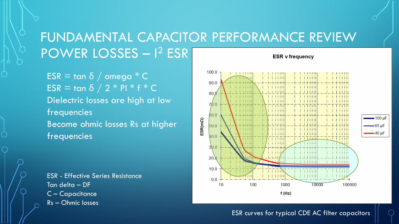
FUNDAMENTAL CAPACITOR PERFORMANCE REVIEWPOWER LOSSES – I2 ESR
ESR = tan δ / omega * C ESR = tan δ / 2 * PI * f * C Dielectric losses are high at low frequencies Become ohmic losses Rs at higher frequencies
ESR curves for typical CDE AC filter capacitors
ESR - Effective Series ResistanceTan delta – DFC – CapacitanceRs – Ohmic losses
13

SINE WAVE FILTER COMBINATIONS & FFT ANALYSIS
•Traditional, with off the shelf filter• Induction motor / VFD
•Mid Frequency, customized•PMM / VFD
•High Frequency, specialized•PMM / HF VFD 14

SO WHAT DOES THIS MEAN FOR THE CAPACITOR?HARMONIC CONTENT FROM TRADITIONAL SYSTEMS
Fast Fourier Transform FFT
ESR =tan δ
2 ∗ π ∗ f ∗ C
5th Harmonic
15

SO WHAT DOES THIS MEAN FOR THE CAPACITOR?HARMONIC CONTENT FROM TRADITIONAL SYSTEMS
•Predominantly fundamental and low frequency harmonic content• 60 Hz and 300 Hz (5th Harmonic)
•Capacitor will need to handle mainly dielectric losses
•Results typically in larger capacitor to handle the power losses
16

SO WHAT DOES THIS MEAN FOR THE CAPACITOR?HARMONIC CONTENT FROM PMM & VFD SYSTEMS
Fast Fourier Transform FFT
ESR =tan δ
2 ∗ π ∗ f ∗ C
20th
Harmonic
17

SO WHAT DOES THIS MEAN FOR THE CAPACITOR?HARMONIC CONTENT FROM PMM / VFD SYSTEMS
•Mainly fundamental and mid frequency harmonic content < 3 kHz
•Some higher frequency content is present ~ 2 kHz
•Capacitor will need to handle mostly dielectric losses and some higher frequency ohmic losses
•Results typically in larger capacitor values18

SO WHAT DOES THIS MEAN FOR THE CAPACITOR?HARMONIC CONTENT FROM HIGH FREQUENCY VFD’S
Fast Fourier Transform FFT
ESR =tan δ
2 ∗ π ∗ f ∗ C49th
Harmonic
Fundamental
19

SO WHAT DOES THIS MEAN FOR THE CAPACITOR?HARMONIC CONTENT FROM HIGH FREQUENCY VFD’S
• Fundamental frequency shifts higher to 300 Hz or 400 Hz
• Higher frequency harmonics are present ~ 20 kHz
• Capacitor will need to cope with a combination of dielectric and ohmic losses
• Capacitance values are typically lower than traditional filter capacitors
20

CAPACITOR DESIGN CHALLENGESHIGH FREQUENCY
• Standard low frequency capacitors
• Harmonic content feedback not given or understood
• Losses due to skin effect
• Ohmic losses
• Dielectric losses
• Misapplication
21

STANDARD HARMONIC CAPACITORLOW FREQUENCY < 3 KHZ HARMONIC CONTENT
• Standard construction
• Ferrous hardware• Steel covers
• Steel terminals
• Capacitor internal section design not so critical
• Not worried about skin effect
22

HARMONIC CONTENT FEEDBACKSO HOW MUCH POWER SHOULD THE CAPACITOR BE REQUIRED TO HANDLE?
• Low frequency, mixed frequency, or high frequency ?
• Fast Fourier Transform FFT• Converts signal from Time Domain to
Frequency Domain
• Shows designer where the harmonic frequencies are and amplitudes
• Keep power generated below capacitor max power dissipation 23
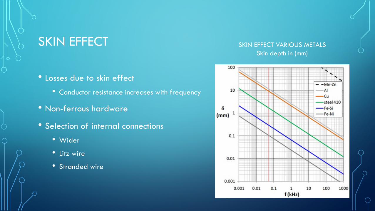
SKIN EFFECT
• Losses due to skin effect• Conductor resistance increases with frequency
• Non-ferrous hardware
• Selection of internal connections• Wider
• Litz wire
• Stranded wire
SKIN EFFECT VARIOUS METALSSkin depth in (mm)
24

HIGH FREQUENCY CAPACITORS CAREFULLY CONSIDER OHMIC LOSSES
• Reduction of metallic resistance throughout all connections
• Metallization
• optimal end spray connection
• lead attach
• lead cross sectional area
• lead geometry
• Non ferrous material throughout
• COMSOL model
Total Ohmic losses
25

HIGH FREQUENCY CAPACITORS CAREFULLY CONSIDER OHMIC LOSSES THERMAL MODEL
26

MISAPPLICATION
• Use standard frequency rated capacitors in high frequency applications
• Thermal overheating of ferrous terminations due to skin effect
• Overheating due to excessive watts lost
• Increased temperature = reduced life
• Forced to use larger and de-rated capacitors in series parallel configuration
• Fewer high frequency capacitors needed 27

HIGH FREQUENCY CAPACITOR CONSIDERATIONS
• Keep Rs as low as possible
• Fast Fourier Transform of harmonic content for power loss analysis• Shows designer what the harmonic frequencies are and amplitudes
• Power calculation critical at higher frequencies • Fundamental frequency drives dielectric losses
• Harmonic frequencies drive resistive losses
• Voltage and current waveforms
• Application temperature 28

RECAP
• Higher frequency power film ac capacitors market driven• Higher switching speed semiconductors
• The move to permanent magnet motors
• Efficiencies, overall costs, and smaller foot prints
• Capacitor• FFT of waveform to be filtered
• Non-ferrous hardware
• Keep generated power losses safely below power handling capability
29

FUTURE TRENDSHIGHER FREQUENCY CAPACITORS• Lower inductance necessary for higher switching frequency
• Capacitor methods for cancelling parasitic inductance
• Bus bar mounting system reducing inductance
• Smaller, more compact capacitors
• Less capacitance required at the higher frequencies
• Higher temperature
• Compactness brings capacitor closer to high temperature power electronics
• Newer high temperature dielectrics required to perform in AC circuits under development
V = L di / dt
30

31