
Report Project 1
132
ABSTRACT Current electrical billing system in Pakistan is manual and there are a lot of complaints with the billing system. Corruption and client’s dissatisfaction is at peak. Number of complaints regarding over charging, error full meter reading and the corruption is increasing day by day. So it’s the need to the hour to develop and efficient and effective method of billing system. An automatic way of meter reading and transmitting it to the central office can cure the problem. This project highlights the use of wireless technology (SMS in this case) for remote acquisition of data from different sites. Wireless technology is fastest growing field of the modern world which finds its application in many different technical fields. The trend of wireless telemetry is now replacing the existing analog electric meters in many countries. Wireless technologies such as GSM & GPRS play a key role to facilitate the remote reading of electricity meters. This project also encompasses the same field. The core idea of this project is monitoring the electricity meters remotely just by using GSM technology, thus making it possible to save time as well as money. Keeping in mind the versatility of the project a lot of advancements can be made in this project thus making the system more efficient and advanced. In chapter 7, proposal for future advancements has been discussed in detail.
-
Upload
adnan-ahmad -
Category
Documents
-
view
112 -
download
1
description
it is the project report of automatic meter reading and billing system with theft control
Transcript of Report Project 1

ABSTRACT
Current electrical billing system in Pakistan is manual and there are a lot of complaints with the billing system. Corruption and client’s dissatisfaction is at peak. Number of complaints regarding over charging, error full meter reading and the corruption is increasing day by day. So it’s the need to the hour to develop and efficient and effective method of billing system. An automatic way of meter reading and transmitting it to the central office can cure the problem. This project highlights the use of wireless technology (SMS in this case) for remote acquisition of data from different sites.
Wireless technology is fastest growing field of the modern world which finds its application in many different technical fields. The trend of wireless telemetry is now replacing the existing analog electric meters in many countries. Wireless technologies such as GSM & GPRS play a key role to facilitate the remote reading of electricity meters. This project also encompasses the same field. The core idea of this project is monitoring the electricity meters remotely just by using GSM technology, thus making it possible to save time as well as money.
Keeping in mind the versatility of the project a lot of advancements can be made in this project thus making the system more efficient and advanced. In chapter 7, proposal for future advancements has been discussed in detail.

SCOPE OF THE PROJECT
In this technology world, electricity has become one of the many necessities of our daily life. Everywhere in homes, offices, factories and markets, the use of electric energy has been increased. It has become a great challenge for electric supply company to cope with this increasing electric energy demand every where in the world. Every country is trying to increase its electric energy generation by installing more and more hydro, nuclear and fossil fuel electric power plants. In this scenario the efficient use of electric energy is very important to save this valuable resource.
The efficient use of electric energy is highly dependant on energy metering. The electromechanical meter is the most common way to measure energy usage employing analog methods. The analog meter’s main disadvantage of electric meter is that it does not provide with the information to make electricity utilization more efficient.
The purpose of this project is to design a way to get analog readings from the analog meter that can provide with more parameters about the consumption of electric energy to make utilization of electric energy more efficient. The meter measures the energy consumed by a consumer and sends that data to a main computer via mobile.
The solution is micro-controller based. This provides great flexibility to measure the many desired features of electricity utilization to make it more efficient.
Design & Fabrication of GSM Based Electric Energy Meter
2

Design & Fabrication of GSM Based Electric Energy Meter
3

PROJECT PICTURE
Design & Fabrication of GSM Based Electric Energy Meter
4

TABLE OF CONTENTS
i. Front page - - - - - - - - - - - - - - - - - - - - - - - - - - - - - - - - - - - - - -1ii. Abstract - - - - - - - - - - - - - - - - - - - - - - - - - - - - - - - - - - - - - - - 3
iii. Scope Of the Project - - - - - - - - - - - - - - - - - - - - - - - - - - - - - - -4iv. Acknowledgements - - - - - - - - - - - - - - - - - - - - - - - - - - - - - - - 5v. Project Picture - - - - - - - - - - - - - - - - - - - - - - - - - - - - - - - - - - -6
CHAPTER 11. Background And Introduction - - - - - - - - - - - - - - - - - - - - - - - - - -9 1.1 Purpose - - - - - - - - - - - - - - - - - - - - - - - - - - - - - - - - - - - - - - - -10 1.2 Project Summary - - - - - - - - - - - - - - - - - - - - - - - - - - - - - - - - - - 10 1.3 What is Signal - - - - - - - - - - - - - - - - - - - - - - - - - - - - - - - - - - - - 10 1.3.1 Why Digital - - - - - - - - - - - - - - - - - - - - - - - - - - - - - - - - - - - 11 1.4 What is Energy Meter - - - - - - - - - - - - - - - - - - - - - - - - - - - - - - - -11 1.5 Wireless Telemetry - - - - - - - - - - - - - - - - - - - - - - - - - - - - - - - - - 11 1.6 Automated Meter Reader - - - - - - - - - - - - - - - - - - - - - - - - - - - - -11 1.7 - Cellular Communication-An Overview - - - - - - - - - - - - - - - - - - - 12 1.7.1 Short messaging service - - - - - - - - - - - - - - - - - - - - - - - - - - -12 1.7.2 SMS subscriptions and hardware - - - - - - - - - - - - - - - - - - - - 12 1.8- Steps towards project- - - - - - - - - - - - - - - - - - - - - - - - - - - - - - - - 13 1.8.1 Acquisition of data from digital meter - - - - - - - - - - - - -- - - -13 1.8.2 Interfacing mobile phone with microcontroller - - - - - - - - - - 14 1.8.3 Interfacing mobile phone with computer - - - - -- - - - - - - - - -15 1.8.4 Establishment of a server - - - - - - - - - - - - - - - - - - - - - - - - - -15 1.8.5 Implementation of the project - - - - - - - - - - - - - - - - - - - - - - -15 1.8.6 Cost of the project in PKRS - - - - - - - - - - - - - - - - - - - - - - - - -16
CHAPTER 22. Wireless Telemetry - - - - - - - - - - - - - - - - - - - - - - - - - - - - - - - - - - - - -17 2.1 Wireless telemetry - - - - - - - - - - - - - - - - - - - - - - - - - - - - - - - - - -18 2.2 Automated meter reader - - - - - - - - - - - - - - - - - - - - - - - - - - - - 19
CHAPTER 33 Introduction to GSM - - - - - - - - - - - - - - - - - - - - - - - - - - - - - - - - - - - - - 22 3.1 Cellular Communication - - - - - - - - - - - - - - - - - - - - - - - - - - - - - - - 23 3.2 Basic components of GSM - - - - - - - - - - - - - - - - - - - - - - - - - - - - - - 23 3.2.1 GSM Network Overview - - - - - - - - - - - - - - - - - - - - - - - - - - - 23 3.2.2 Mobile Station (MS) - - - - - - - - - - - - - - - - - - - - - - - - - - - - - - 25 3.2.3 Base Station System (BSS) - - - - - - - - - - - - - - - - - - - - - - - - - 28 3.3 Transcoder (XCDR) - - - - - - - - - - - - - - - - - - - - - - - - - - - - - - - - - - - 32 3.4 Network Switching System - - - - - - - - - - - - - - - - - - - - - - - - - - - - -- 34 3.5 Operations and Maintenanc0e System - - - - - - - - - - - - - - - - - - - - - - 42 3.6 The Network in Reality - - - - - - - - - - - - - - - - - - - - - - - - - - - - - - - - 45
CHAPTER 44 Introduction to Microcontroller - - - - - - - - - - - - - - - - - - - - - - - - - - - - - -47 4.1 What is a Microcontroller - - - - - - - - - - - - - - - - - - - - - - - - - - - - - - - -48
Design & Fabrication of GSM Based Electric Energy Meter
5

4.1.1 Arduino - - - - - - - - - - - - - - - - - - - - - - - - - - - - - - - - - - - - - - - - -51 4.1.2 Platforms from Parallax, Inc - - - - - - - - - - - - - - - - - - - - - - - - - - 51 4.1.3 PICAXE - - - - - - - - - - - - - - - - - - - - - - - - - - - - - - - - - - - - - - - - - 51 4.1.4 ZX-24, ZX-40, ZX-44 - - - - - - - - - - - - - - - - - - - - - - - - - - - - - - - 52 4.2 PIC Microcontroller - - - - - - - - - - - - - - - - - - - - - - - - - - - - - - - -- - - - - 52 4.2.1 Core Architecture of the 8-bit CPUs - - - - - - - - - - - - - - - - - - - - - 53 4.2.2 Data Space (RAM) - - - - - - - - - - - - - - - - - - - - - - - - - - - - - - - - - 53 4.2.3 Code Space - - - - - - - - - - - - - - - - - - - - - - - - - - - - - - - - - -- - - - - 54 4.2.4 Word Size - - - - - - - - - - - - - - - - - - - - - - - - - - - - - - - - - - - - - - - 54 4.2.5 Stacks - - - - - - - - - - - - - - - - - - - - - - - - - - - - - - - - - - - - - - - - - - 54 4.2.6 Instruction Set - - - - - - - - - - - - - - - - - - - - - - - - - - - - - - - - - - - -55 4.3 High-Performance RISC CPU - - - - - - - - - - - - - - - - - - - - - - - - - - - - - -55 4.4 Features - - - - - - - - - - - - - - - - - - - - - - - - - - - - - - - - - - - - - - - - - - - - - 56 4.4.1 Special Microcontroller Features - - - - - - - - - - - - - - - - - - - - - - -56 4.4.2 Peripheral Features - - - - - - - - - - - - - - - - - - - - - - - - - - - - - - - - 57 4.4.3 Analog Features - - - - - - - - - - - - - - - - - - - - - - - - - - - - - - - - - - -57
CHAPTER 5 5 Software Tools - - - - - - - - - - - - - - - - - - - - - - - - - - - - - - - - - - - - - - - - - - -58
5.1 Visual Basic - - - - - - - - - - - - - - - - - - - - - - - - - - - - - - - - - - - - - - - - - - 59 5.1.1 Language Features - - - - - - - - - - - - - - - - - - - - - - - - - - - - - - - - 60 5.2 Microsoft Office Access - - - - - - - - - - - - - - - - - - - - - - - - - - - - - - - - -61 5.2.1 Features - - - - - - - - - - - - - - - - - - - - - - - - - - - - - - - - - - - - - - - - 61 5.2.2 Uses - - - - - - - - - - - - - - - - - - - - - - - - - - - - - - - - - - - - - - - - - - - 62 5.3 Crystal Report - - - - - - - - - - - - - - - - - - - - - - - - - - - - - - - - - - - - - - - 62 5.3.1 Creating Reports - - - - - - - - - - - - - - - - - - - - - - - - - - - - - - - - - -62 5.3.2 Running Reports Locally - - - - - - - - - - - - - - - - - - - - - - - - - - - 63
CHAPTER 66 Hardware Details- - - - - - - - - - - - - - - - - - - - - - - - - - - - - - - - - - - - - - - -- 64 6.0 Hardware Details- - - - - - - - - - - - - - - - - - - - - - - - - - - - - - - - - - - - - - - -65
6.1 Analog Energy Meter- - - - - - - - - - - - - - - - - - - - - - - - - - - - - - - - - - - - - 65 6.1.1 Overview- - - - - - - - - - - - - - - - - - - - - - - - - - - - - - - - - - - - - - - - - 65 6.1.2 Electromechanical meters- - - - - - - - - - - - - - - - - - - - - - - - - - - - - -65 6.1.3 Technology - - - - - - - - - - - - - - - - - - - - - - - - - - - - - - - - - - - - -- - - 66 6.1.4 Working- - - - - - - - - - - - - - - - - - - - - - - - - - - - - - - - - - - - - - - - - - 67 6.1.5 Accuracy- - - - - - - - - - - - - - - - - - - - - - - - - - - - - - - - - - - - - - - - - 68 6.2 Opto Coupler / Opto Isolator- - - - - - - - - - - - - - - - - - - - - - - - - - - - - - - 68 6.3 Power Supply- - - - - - - - - - - - - - - - - - - - - - - - - - - - - - - - - - - - - - - - - - 69 6.4 LC circuit- - - - - - - - - - - - - - - - - - - - - - - - - - - - - - - - - - - - - - - - - - - - - 69 6.5 Voltage Regulator (LM 311) - - - - - - - - - - - - - - - - - - - - - - - - - - - - - - - - 70 6.6 LCD - - - - - - - - - - - - - - - - - - - - - - - - - - - - - - - - - - - - - - - - - - - - - - - - -70
CHAPTER 77 Future Advancements in Project - - - - - - - - - - - - - - - - - - - - - - - - - - - - -71 7.1 Future Advancement in Project - - - - - - - - - - - - - - - - - - - - - - - - - - - 72 7.1 Duplex Communication - - - - - - - - - - - - - - - - - - - - - - - - - - - - - - - - - 72 7.2 Power Shut Down - - - - - - - - - - - - - - - - - - - - - - - - - - - - - - - - - - - - - - 73
Design & Fabrication of GSM Based Electric Energy Meter
6

7.3 Data Storage - - - - - - - - - - - - - - - - - - - - - - - - - - - - - - - - - - - - - - - - - - 74 7.4 Composite/Multi phases meter - - - - - - - - - - - - - - - - - - - - - - - - - - - -75 7.5 Networking - - - - - - - - - - - - - - - - - - - - - - - - - - - - - - - - - - - - - - - - - - - 76
APPENDICESAppendix I - - - - - - - - - - - - - - - - - - - - - - - - - - - - - - - - - - - - - - - - - - - - - - - -77Appendix II - - - - - - - - - - - - - - - - - - - - - - - - - - - - - - - - - - - - - - - - - - - - - - - 84
Appendix III - - - - - - - - - - - - - - - - - - - - - - - - - - - - - - - - - - - - - - - - -- - -- - - 85 Acronyms- - - - - - - - - - - - - - - - - - - - - - - - - - - - - - - - - - - - - - - - - - - - - - - - - 94 References - - - - - - - - - - - - - - - - - - - - - - - - - - - - - - - - - - - - - - - - - - - - - - - - 96
CHAPTER NO.1
BACKGROUND AND INTRODUCTION
Design & Fabrication of GSM Based Electric Energy Meter
7

Important Points:
Purpose of the project Scope of the project Overview of Wireless telemetry Introduction to GSM network Acquisition of data from digital meter Project Budget
1.1 - PURPOSE:
Currently WAPDA has installed magnetic coil type mechanical energy
meters.
There are a lot of complaints regarding electrical billing system of
WAPDA from the valued customers.
The purpose of the project is to devise a better way for metering so that
complaints can be removed. Corruption involved in the billing system can
also be eliminated.
1.2 - PROJECT SUMMARY:
The task in this project is to devise an efficient way for measuring the
energy consumed by a consumer and transmitting it to the central office.
Phase-I is to get analog readings from an analog meter and convert it
into digital by attaching color sensors and then interfacing of the sensor
with the microcontroller.
Mobile phone is programmed so that it generates SMS after every two
minutes and sends it to the central office. Another mobile phone is
interfaced with a computer and a server is established. There an operator
sitting at the pc receives SMS containing the meter reading of that time
after every two minutes.
1.3 - WHAT IS A SIGNAL:
Design & Fabrication of GSM Based Electric Energy Meter
8

A signal is a piece of information in a sinusoidal wave form. A signal can
be analog, digital or hybrid. A signal that has continuously varying
voltages, frequencies, and phases is called an analog signal. A type of
signal that encodes voice, video, or data transmitted over wire or through
the air, and is commonly represented as an oscillating wave. An analog
signal can take any value in a range and changes smoothly between
values. A digital signal is a transmission signal that carries information in
a discontinuous stream of on/off pulses. A way of sending voice, video, or
data that reconstructs the signals using binary codes (1s and 0s) for
transmission through wire, fiber optic cable, videoconference, or over air
techniques. Digital audio/video signals represented by discrete variations
(in voltage, frequency, amplitude, location, etc.) can be transmitted
faster and more accurately than analog signals.
1.3.1 - Why Digital?
Digital signals are not subject to the interference, signal loss, and noise
as compared to analog signal. It can be reconstructed into a perfect
replica of the original source.
Digital data can be encrypted to provide some measure of protection
against unwanted viewing or listening. They have low cost.
1.4 - WHAT IS AN ENERGY METER?
An electric meter or energy meter is a device that measures the amount
of electric energy supplied to a residence or business. The person that
uses the electricity is called the customer of an electric company.
The most common unit of measurement on the electricity meter is the
kilowatt-hour which is equal to the amount of energy used by a load of
one kilowatt over a period of one hour, or 3,600,000 joules. Energy
meters can be both analog and digital.
Design & Fabrication of GSM Based Electric Energy Meter
9

1.5 - WIRELESS TELEMETRY
Wireless telemetry can be defined as machine-to-machine
communications via a radio link. This is often the transfer of data from
sensors for remote monitoring or data collation purposes. Typical
applications include:
Building alarms
Vehicle and boat alarms
Remote meter reading
Environmental applications, such as weather
stations and earthquake status monitoring
Border access control
Monitoring of water, gas or oil pipelines/facilities
1.6 - AUTOMATED METER READER
Automated Meter Reading is the technology of collecting data from water
meters or energy meters and transferring that data to central database
for billing and analyzing. It has following benefits and uses:
AMR reduces the need for meter reader to gather meter reading
each month
AMR technology is used to improve customer service
1.7 - CELLULAR COMMUNICATION - AN OVERVIEW:
A cellular telephone system links mobile station (MS) subscribers into the
public telephone system or to another cellular system’s MS subscriber.
Information sent between the MS subscriber and the cellular network
uses radio communication. This removes the necessity for the fixed
wiring used in a traditional telephone installation. Due to this, the MS
subscriber is able to move around and become fully mobile, perhaps
traveling in a vehicle or on foot.
Design & Fabrication of GSM Based Electric Energy Meter
10

1.7.1 - Short Messaging Service:
The Short Message Service (SMS) allows text messages to be sent and
received to and from mobile telephones. The text can be comprised of
words or numbers or an alphanumeric combination. The SMS is a store
and forward service ---short messages are not sent directly from sender
to recipient, but through an SMS Center
1.7.2 - SMS Subscriptions and Hardware:
A subscription to a mobile telephone network that supports
SMS.
Use of SMS must be enabled for that user (automatic access to
the SMS is given by some mobile network operators, others
charge a monthly subscription and require a specific opt-in to
use the service).
Mobile phone or GSM modem that supports SMS.
Knowledge of how to send or read a short message using their
specific model of mobile phone or GSM modem.
A destination to send a short message to, or receive a message
from.
1.8 - STEPS TOWARDS PROJECT:
Following will be the steps towards project
Simulation Model
To get digital readings from electromechanical meter
To interface meter with the microcontroller
Design & Fabrication of GSM Based Electric Energy Meter
11

To interface microcontroller with the mobile
Establishment of a server
To transmit readings to the server
Development of database for billing
Project Report
Details of each part will be discussed in the subsequent pages.
1.8.1 - Acquisition of Data from Digital Meter
PROBLEM
Current and voltage is analog by default
There fore they must be converted in to digital form
SOLUTION # 1
Open the meter.
Put a cut at its plate and attached an IR Tx n Rx on top and bottom
of it.
As the plate rotates, on each cut, we will get an IR signal at the
output.
Thus analog information is converted in to digital one
SOLUTION # 2
Attach color sensors at the top of the meter.
Detect the black spot on the plate.
Interface the sensor with microcontroller (preferably pic ).
Microcontroller is programmed so that it increments one in a
register each time the IR signal arrives.
SOLUTION # 3:
Design & Fabrication of GSM Based Electric Energy Meter
12

The 3rd approach is to use current transformers and potential
transformers. With the help these two transformers, we can calculate the
energy consumed by a customer. With the help of potential transformer,
voltage can be obtained and with the help of current transformer, current
can be obtained.
Suppose it is required to determine the energy consumed by a house
hold, we can do it in the following way.
Voltage and current are sampled at an appropriate rate through
Analog to Digital converter
From the plot of these samples phase difference between the
current and voltage is determined by using some computer tool like
MATLAB.
From the phase difference, power factor is determined.
Finally real power, imaginary power is determined in the micro-
controller.
1.8.2 - Interfacing Mobile Phone with Microcontroller:
It’s a serial interface.
Programming of the mobile phone from the microcontroller
so that it may generate a SMS each time.
Design & Fabrication of GSM Based Electric Energy Meter
13

FIG 1.1: Interfacing of mobile phone with microcontroller
1.8.3 - Interfacing mobile Phone with Computer:
Interfacing of another mobile phone with a computer.
It’s a serial interface directly with the data cable.
Design & Fabrication of GSM Based Electric Energy Meter
14
INTERFACE

FIG 1.2: Interface of mobile phone with computer
1.8.4 - Establishment of Server:
Establishment of the server at a pc is in visual basic.
The operator receives the SMS containing the meter reading of
that time after two minutes.
LCD is interfaced to the microcontroller.
1.8.5 - Implementation of the Project:
Final step is to implement the project. Following hard wave was used for
the implementation of the project.
2 Mobile phone
Energy meter
PIC Programmer
2 Data cables
PIC 16F877A Microcontroller
LCD
Design & Fabrication of GSM Based Electric Energy Meter
15
INTERFACE

Breadboard
Optocoupler
Shimmit trigger
Resistors, Capacitors, Inductors, Vero board, Soldering Machine
1.8.6 - Cost of the Project in PKRS:
COMPONENTS PRICE
Energy Meter 850
Opto-coupler 50
Power Supply 100
Mobile 900
PIC 16F877A 240
Ziff Socket 90
Miscellaneous 200
Total 2430
Design & Fabrication of GSM Based Electric Energy Meter
16
CHAPTER NO.2
WIRELESS TELEMETRY
Important Points:
Wireless Telemetry
Automatic Meter Reader
Design & Fabrication of GSM Based Electric Energy Meter
17

2.1 - WIRELESS TELEMETRY
Wireless telemetry can be defined as machine-to-machine
communications via a radio link. This is often the transfer of data from
sensors for remote monitoring or data collation purposes. Typical
applications include:
Building alarms
Vehicle and boat alarms
Remote meter reading
Environmental applications, such as weather
stations and earthquake status monitoring
Border access control
Monitoring of water, gas or oil pipelines/facilities
It is often tempting to consider addressing a telemetry requirement with
a standard-based solution such as GSM/GPRS or 3G. Whilst these
established standards do offer well defined hardware and software
specifications and have an existing network infrastructure, they have not
been optimized for the specific telemetry application under
consideration. The power consumption, terminal equipment cost, data
transport cost and/or data rate are unlikely to be all optimal for any given
application. Other standard-based, wireless data transfer solutions such
as Bluetooth, DECT or 802.11b may offer more attractive cost models but
may fall short in other ways such as achievable range or battery life.
Key requirements of many of the telemetry applications mentioned above
include:
Low unit cost
Low data transport costs
Long battery life (low operating power)
Adequate range
Low/moderate data rates
Design & Fabrication of GSM Based Electric Energy Meter
18

A custom-designed, application-specific telemetry system should
result in the optimum solution for a given application because
the correct trade-offs between the conflicting requirements can
be made during the design process.
In the case of the remote utility meter reading system, a low cost radio
transmitter is fitted to or integrated with existing metering equipment.
An interface to that equipment allows local data storage shows the
remote customer premises equipment for both an electricity meter and a
gas meter. Data is transmitted from the remote terminal to a base station
with a subsequent back-haul link to a central server. The rate of
transmission from the meter is programmable from several times per
hour to daily or even weekly.
The adoption of a custom telemetry solution allows the system
architecture and radio interface technology to be tailored to minimize the
cost, complexity and power consumption of the remote unit at the meter.
Although it is essential to keep the cost of the remote unit very low, it is
also necessary to ensure that the communications range of the radio link
is adequate in order to keep the infrastructure deployment costs down.
The key to achieving these goals is the development of a sophisticated,
custom radio communications protocol and the use of digital signal
processing in the base station receiver. The resulting system supports
packet transmissions of nominally 2kbps with payloads typically in the
range 32-64 bytes. The remote unit is a narrow band, phase-modulated
transmitter operating on a randomized time and frequency basis. The
base station receiver utilizes an advanced, wideband multi channel DSP
architecture able to decode up to forty simultaneously received signals. A
single base station is able to support several thousand remote terminals.
2.2 - AUTOMATED METER READER
Using wireless radio transmitters, AMR remotely reads customer meters
and then transfers the data into the billing system. AMR will reduce the
Design & Fabrication of GSM Based Electric Energy Meter
19

need for meter readers to manually gather utility meter readings each
month. Many utilities are using AMR as a way to improve customer
service and control their meter reading costs, especially in areas with
fenced yards, dogs, landscaping and other issues that make accessing
meters difficult or unsafe. Benefits include:
Improved customer service, which includes:
o Minimizing the need to access customer property
to read meters
o Reducing customer complaints and damage
claims resulting from monthly visits to customer
site
o Call resolution improvement – billing complaint
calls will be handled more quickly due to
availability of more frequent meter readings
o No need for customer to read their own meters
due to meter access issues
Controlled meter reading costs
Enhanced customer convenience
Fewer employee injuries, especially in areas with fenced
yards, dogs and landscaping
Improved billing accuracy
A reduction in operational costs
There are several AMR technologies in today's market, ranging from
walk-by, drive-by, fixed networks to telemetry-based systems. We
are planning to deploy a wireless fixed network system. There are three
components:
Customer Utility Meter - with wireless radio transmission
Data Relay Box - usually attached to a street light
Design & Fabrication of GSM Based Electric Energy Meter
20

Data collection through a telecom transmission,
management and billing system
As meters get older they may become less accurate and need to be
replaced, and it makes good business sense to upgrade to this new
technology at this time. Through the reduced need for on-site manual
meter readings and other efficiencies, the system is expected to pay for
itself within approximately 10 years of installation.
Only meter readings and meter or module numbers are transmitted.
Personal customer information will not be transmitted. We use wireless
packet data technology to keep information private and secure. Wireless
packet data was originally developed by the U.S. military for secure
communications. Features of the AMR electric endpoint modules include
built-in power outage notification, reverse rotation detection, magnetic
tamper detection, power restoration notification and redundant
transmissions.
The transmitting devices operate in compliance with FCC regulations to
avoid interference with other electronic devices.
The only significant change to utility service will be that meter readers
will not need to visit the property monthly to collect the meter readings.
Service personnel may visit the meter periodically to confirm proper
operation or perform routine maintenance.
The primary objective of this project is to design a system that monitors
the readings of electricity meters at the control room without meter
readers visits. - A fine solution for the electric power supplying
companies who wants to access and record the power consumption
information at consumer premises from remote distances.
Wireless technology is widely used across different household appliances,
and it is highly accepted due to the mobility it brings for the owners. The
current range of the wireless doorbell cannot fulfill the demand for some
Design & Fabrication of GSM Based Electric Energy Meter
21

people nowadays as modern citizens are now obliged to be more flexible
and highly mobilized for maximizing their efficiency.
Longer-range remote electrical goods have become a necessary trend for
the next generation of household appliances as the market demands
higher mobility. Accessing the cellular network provides the essential
range for this thesis project. Constructing wireless doorbell system, that
is GSM/GPRS network compatible, would bring modern households into
an extended life style.
CHAPTER NO.3
INTRODUCTION TO GSM
Design & Fabrication of GSM Based Electric Energy Meter
22

Important Points:
Basic concepts of GSM
Basic components of GSM
Network switching system
Network in reality
3.1 - CELLULAR COMMUNICATION
A cellular telephone system links mobile station (MS) subscribers into the
public telephone system or to another cellular system’s MS subscriber.
Information sent between the MS subscriber and the cellular network
uses radio communication. This removes the necessity for the fixed
wiring used in a traditional telephone installation. Due to this, the MS
subscriber is able to move around and become fully mobile, perhaps
traveling in a vehicle or on foot.
3.2 - BASIC COMPONENTS OF GSM
3.2.1 - GSM Network Overview
The diagram below shows a simplified GSM network. Each network
component is designed to communicate over an interface specified by the
GSM standards. This provides flexibility and enables a network provider
Design & Fabrication of GSM Based Electric Energy Meter
23

to utilize system components from different manufacturers. For example
Motorola Base Station System (BSS) equipment may be coupled with an
Ericsson Network Switching System.
The principle component groups of a GSM network are
The Mobile Station (MS)
This consists of the mobile telephone, fax machine etc. This is the
part of the network that the subscriber will see.
The Base Station System (BSS)
This is the part of the network which provides the radio
interconnection from the MS to the land-based switching equipment.
The Network Switching System
This consists of the Mobile services Switching Centre (MSC) and its
associated System-control databases and processors together with the
required interfaces. This is the part which provides for interconnection
between the GSM network and the Public Switched Telephone Network
(PSTN).
Design & Fabrication of GSM Based Electric Energy Meter
24
Fig 3.1: Showing architecture of GSM network
Design & Fabrication of GSM Based Electric Energy Meter
25

The Operations and Maintenance System
This enables the network provider to configure and maintain the
network from a central location.
In the text to follow each component group is discussed in detail
3.2.2 - Mobile Station (MS)
The MS consists of two parts,
Mobile Equipment (ME)
Subscriber Identity module (SIM) (An electronic ‘smart card’ )
The ME is the hardware used by the subscriber to access the network.
The hardware has an identity number associated with it, which is unique
for that particular device and permanently stored in it. This identity
number is called the International Mobile Equipment Identity
(IMEI) and enables the network operator to identify mobile equipment
which may be causing problems on the system.
The SIM is a card which plugs into the ME. This card identifies the MS
subscriber and also provides other information regarding the service that
subscriber should receive. The subscriber is identified by an identity
number called the International Mobile Subscriber Identity (IMSI).
Mobile Equipment may be purchased from any store but the SIM must be
obtained from the GSM network provider. Without the SIM inserted, the
ME will only be able to make emergency calls. By making a distinction
between the subscriber identity and the ME identity, GSM can route calls
and perform billing based on the identity of the ‘subscriber’ rather than
the equipment or its location.
Mobile Equipment (ME)
The ME is the only part of the GSM network which the subscriber
will really see. There are three main types of ME, these are listed below:
Vehicle Mounted
Design & Fabrication of GSM Based Electric Energy Meter
26

These devices are mounted in a vehicle and the antenna is
physically mounted on the outside of the vehicle.
Design & Fabrication of GSM Based Electric Energy Meter
27

Portable Mobile Unit
This equipment can be handheld when in operation, but the
antenna is not connected to the handset of the unit.
Hand portable Unit
This equipment comprises of a small telephone handset not much
bigger than a calculator. The antenna is be connected to the handset.
The ME is capable of operating at a certain maximum power output
dependent on its type and use. These mobile types have distinct features
which must be known by the network, for example their maximum
transmission power and the services they support. The ME is therefore
identified by means of a Classmark. The classmark is sent by the ME in
its initial message.
Class Mark
The following pieces of information are held in the classmark
Revision Level
Identifies the phase of the GSM specifications that the mobile
complies with.
RF Power Capability –
The maximum power the MS is able to transmit, used for power
control and handover preparation. This information is held in the mobile
power class number.
Ciphering Algorithm
Indicates which ciphering algorithm is implemented in the MS. There
is only one
Algorithm (A5) in GSM phase 1, but GSM phase 2 specifies different
algorithms
(A5/0–A5/7).
Frequency Capability
Design & Fabrication of GSM Based Electric Energy Meter
28

Indicates the frequency bands the MS can receive and transmit on.
Currently all
GSM MSs use one frequency band, in the future this band will be
extended but not all MSs will be capable of using it.
Short Message Capability
Indicates whether the MS is able to receive short messages or not.
POWER CLASSPOWER
OUTPUT(Watts)1 20(Not Used Now)
2 8
3 5
4 2
5 0.8
Subscriber Identity Module (SIM)
The SIM as mentioned previously is a “smart card” which plugs
into the ME and contains information about the MS subscriber hence
the name Subscriber Identity Module.
The SIM contains several pieces of information:
International Mobile Subscriber Identity (IMSI)
This number identifies the MS subscriber. It is only transmitted
over the air during initialization.
Temporary Mobile Subscriber Identity (TMSI)
This number identifies the subscriber, it is periodically changed by
the system management to protect the subscriber from being identified
by someone attempting to monitor the radio interface.
Location Area Identity (LAI)
Identifies the current location of the subscriber.
Design & Fabrication of GSM Based Electric Energy Meter
29

Subscriber Authentication Key (Ki)
This is used to authenticate the SIM card.
Mobile Subscriber International Services Digital Network
(MSISDN) Number
This is the telephone number of the mobile subscriber. It is
comprised of a country code, a network code and a subscriber number.
Most of the data contained within the SIM is protected against reading
(Ki) or alterations (IMSI). Some of the parameters (LAI) will be
continuously updated to reflect the current location of the subscriber.
The SIM cards, and the high degree of inbuilt system security, provide
protection of the subscriber’s information and protection of networks
against fraudulent access. SIM cards are designed to be difficult to
duplicate. The SIM can be protected by use of Personal Identity Number
(PIN) password, similar to bank/credit charge cards, to prevent
unauthorized use of the card.
The SIM is capable of storing additional information such as accumulated
call charges. This information will be accessible to the customer via
handset/keyboard key entry. The SIM also executes the Authentication
Algorithm.
Fig 3.2: Actual Size of SIM
Design & Fabrication of GSM Based Electric Energy Meter
30

Fig 3.3: Mini SIM card
3.2.3 - Base Station System (BSS)
The GSM Base Station System is the equipment located at a cell site. It
comprises a combination of digital and RF equipment. The BSS provides
the link between the MS and the MSC. The BSS communicates with the
MS over the digital air interface and with the MSC via 2 Mbit/s links.
The BSS consists of three major hardware components:
The Base Transceiver Station – BTS
The BTS contains the RF components that provide the air interface for
a particular cell. This is the part of the GSM network which
communicates with the MS. The antenna is included as part of the
BTS.
The Base Station Controller – BSC
The BSC as its name implies provides the control for the BSS. The
BSC communicates directly with the MSC. The BSC may control single
or multiple BTSs.
The Transcoder – XCDR
The transcoder is used to compact the signals from the MS so that
they are more efficiently sent over the terrestrial interfaces. Although
the transcoder is considered to be a part of the BSS, it is very often
located closer to the MSC.
The transcoder is used to reduce the rate at which the traffic
(voice/data) is transmitted over the air interface. Although the
transcoder is part of the BSS, it is often found physically closer to the
NSS to allow more efficient use of the terrestrial links.
Design & Fabrication of GSM Based Electric Energy Meter
31

Fig 3.4: Showing Transcoder and BTS link
Base Transceiver Station – BTS
The BTS provides the air interface connection with the MS. It also
has a limited amount of control functionality which reduces the
amount of traffic passing between the BTS and BSC. The functions of
the BTS are shown opposite. Each BTS will support 1 or more cells.
Base Station Controller (BSC)
As previously mentioned, the BSC provides the control for the BSS.
Any operational information required by the BTS will be received via
the BSC. Likewise any information required about the BTS (by the
OMC for example) will be obtained by the BSC.
The BSC incorporates a digital switching matrix, which it uses to
connect the radio channels on the air interface with the terrestrial
circuits from the MSC. The BSC switching matrix also allows the BSC
to perform “handovers” between radio channels on BTSs, under its
control, without involving the MSC.
Design & Fabrication of GSM Based Electric Energy Meter
32

BSS Functionality Control BSS Functionality Control
Terrestrial Channel Management
BSC EncryptionBSC/BTS
Channel Allocation BSC PagingBSC/BTS
Radio Channel Management
BSCControl Channel Management
BSC/BTS
Channel Configuration Management
BSCMeasurement Reporting
BTS
Handover Control BSCChannel Coding/Decoding
BTS
Frequency Hopping BSC/BTS Timing Advance BTS
Traffic Channel Management
BSC/BTSIdle Channel Observation
BTS
Where the BSC and BTS are both shown to control a function, the control
is divided
between the two, or may be located wholly at one.
SUMMARY OF THE FUNCTIONS OF BSC AND BTS
BSC BTS
Control one or more BTS Contains RF hardware
Switches traffic and signaling to\from the BTS and MSC
Limited control functionality
Connects terrestrial channels and circuits on air interface
Supports 1 or more cells
Controls handovers performed by BTS under its control
BSS Configurations
As we have mentioned, a BSC may control several BTSs, the
maximum number of BTSs which may be controlled by one BSC is not
specified by GSM. Individual manufacturer’s specifications may vary
greatly. The BTSs and BSC may either be located at the same cell site
“co-located”, or located at different sites “Remote”. In reality most
Design & Fabrication of GSM Based Electric Energy Meter
33

BTSs will be remote, as there are many more BTSs than BSCs in a
network.
Another BSS configuration is the daisy chain. A BTS need not
communicate directly with the BSC which controls it, it can be
connected to the BSC via a chain of BTSs. Daisy chaining reduces the
amount of cabling required to set up a network as a BTS can be
connected to its nearest BTS rather than all the way to the BSC.
Problems may arise when chaining BTSs, due to the transmission
delay through the chain. The length of the chain must, therefore, be
kept sufficiently short to prevent the round trip speech delay
becoming too long.
Other topologies are also permitted, including stars and loops. Loops
are used to introduce redundancy into the network, for example if a
BTS connection was lost, the BTS may still be able to communicate
with the BSC if a
second connection
is available.
Design & Fabrication of GSM Based Electric Energy Meter
34

Fig 3.5: Showing BSS configuration
3.3 - TRANSCODER (XCDR)
The Transcoder (XCDR) is required to convert the speech or data output
from the MSC (64 kbit/s PCM), into the form specified by GSM
specifications for transmission over the air interface, that is, between the
BSS and MS (64 kbit/s to 16 kbit/s and vice versa) The 64 kbit/s Pulse
Code Modulation (PCM) circuits from the MSC, if transmitted on the air
interface without modification, would occupy an excessive amount of
radio bandwidth.
This would use the available radio spectrum inefficiently. The required
bandwidth is therefore reduced by processing the 64 kbit/s circuits so
that the amount of information required to transmit digitized voice falls
to a gross rate of 16 kbit/s. The transcoding function may be located at
the MSC, BSC, or BTS. The content of the 16 kbit/s data depends on the
coding algorithm used. There are two speech coding algorithms available
and selecting which one to use depends on the capabilities of the mobile
equipment and the network configuration.
The Full Rate speech algorithm is supported by all mobiles and networks.
It produces 13 kbit/s of coded speech data plus 3 kbit/s of control data
which is commonly referred to as TRAU data (Transcoder Rate Adaption
Unit). The TRAU data on the downlink will be used by the BTS and
therefore removed from the 13 k of speech data before transmission on
the air interface. the 13 kbit/s of speech data is processed at the BTS to
form a gross rate of 22.8 kbit/s on the air interface which includes
forward error correction. In the uplink direction the BTS adds in TRAU
data which will be used by the transcoder.
Enhanced Full Rate is an improved speech coding algorithm and is only
supported by
Phase 2+ mobiles and is optional in the Network. It produces 12.2 kbit/s
from each 64 kbit/s PCM channel. The TRAU data in this case is made up
to 3.8 kbit/s to keep the channel rate to and from the BTS at 16 kbit/s as
Design & Fabrication of GSM Based Electric Energy Meter
35

for Full Rate. As with Full Rate the TRAU data is used at the BTS and
Transcoder.
For data transmissions the data is not transcoded but data rate adapted
from 9.6 kbit/s (4.8 kbit/s or 2.4 kbit/s may also be used) up to a gross
rate of 16 kbit/s for transmission over the terrestrial interfaces, again
this 16 kbit/s contains a 3 kbit/s TRAU. As can be seen from the diagram
opposite, although the reason for transcoding was to reduce the data rate
over the air interface, the number of terrestrial links is also reduced
approximately on a 4:1 ratio.
Fig 3.6: Showing C-7 Signaling
3.4 - NETWORK SWITCHING SYSTEM
The Network Switching System includes the main switching
functions of the GSM network. It also contains the databases required for
Design & Fabrication of GSM Based Electric Energy Meter
36

subscriber data and mobility management. Its main function is to manage
communications between the GSM network and other
telecommunications networks.
The components of the Network Switching System are listed below:
Mobile Services Switching Centre – MSC
Home Location Register – HLR
Visitor Location Register – VLR
Equipment Identity Register – EIR
Authentication Centre – AUC
InterWorking Function – IWF
Echo Canceller – EC
In addition to the more traditional elements of a cellular telephone
system, GSM has
Location Register network entities. These entities are the Home Location
Register
(HLR), Visitor Location Register (VLR), and the Equipment Identity
Register (EIR). The location registers are database-oriented processing
nodes which address the problems of managing subscriber data and
keeping track of a MSs location as it roams around the network.
Functionally, the Interworking Function and the Echo Cancellers may be
considered as parts of the MSC, since their activities are inextricably
linked with those of the switch as it connects speech and data calls to
and from the MSs.
MOBILE SERVICES SWITCHING CENTRE (MSC)
The MSC is included in the GSM system for call-switching. Its overall
purpose is the same as that of any telephone exchange. However,
because of the additional complications involved in the control and
security aspects of the GSM cellular system and the wide range of
Design & Fabrication of GSM Based Electric Energy Meter
37

subscriber facilities that it offers, the MSC has to be capable of fulfilling
many additional functions.
Fig 3.7: Showing Network Switching System
The MSC will carry out several different functions depending upon its
position in the network. When the MSC provides the interface between
the PSTN and the BSSs in the GSM network it will be known as a
GATEWAY MSC. In this position it will provide the switching required
for all MS originated or terminated traffic. Each MSC provides service to
MSs located within a defined geographic coverage area, the network
typically contains more than one MSC. One MSC is capable of supporting
a regional capital with approximately one million inhabitants. An MSC of
this size will be contained in about half a dozen racks.
The functions carried out by the MSC are listed below:
Call Processing
Design & Fabrication of GSM Based Electric Energy Meter
38

Includes control of data/voice call setup, inter-BSS and inter-MSC
handovers and control of mobility management (subscriber validation
and location).
Operations and Maintenance Support
Includes database management, traffic metering and measurement,
and a
man–machine interface.
Internetwork Interworking
Manages the interface between the GSM network and the PSTN.
Billing
Collects call billing data.
Home Location Register (HLR)
The HLR is the reference database for subscriber parameters.
Various identification numbers and addresses are stored, as well as
authentication parameters. This information is entered into the
database by the network provider when a new subscriber is added to
the system.
The HLR database contains the master database of all the subscribers
to a GSM PLMN. The data it contains is remotely accessed by all the
MSCs and the VLRs in the network and, although the network may
contain more than one HLR, there is only one database record per
subscriber – each HLR is therefore handling a portion of the total
subscriber database. The subscriber data may be accessed by either
the IMSI or the MSISDN number. The data can also be accessed by an
MSC or a VLR in a different PLMN, to allow inter-system and inter-
country roaming.
HLR contains the following information
Design & Fabrication of GSM Based Electric Energy Meter
39

Subscriber ID(IMSI & MSISDN)
Current subscriber VLR
Supplementary services subscribed to
Supplementary services number(e.g current forwarding
number)
Subscriber status(Registered or Deregistered)
Authentication key and AUC functionality
Mobile subscriber roaming number
Visitor Location Register (VLR)
The VLR contains a copy of most of the data stored at the HLR. It
is, however, temporary data which exists for only as long as the
subscriber is “active” in the particular area covered by the VLR. The
VLR database will therefore contain some duplicate data as well as
more precise data relevant to the subscriber remaining within the VLR
coverage.
The VLR provides a local database for the subscribers wherever they
are physically located within a PLMN, this may or may not be the
“home” system. This function eliminates the need for excessive and
time-consuming references to the “home” HLR database.
The additional data stored in the VLR is listed below:
Mobile status (busy/free/no answer etc.).
Location Area Identity (LAI).
Temporary Mobile Subscriber Identity (TMSI).
Mobile Station Roaming Number (MSRN).
Location Area Identity
Cells within the Public Land Mobile Network (PLMN) are grouped
together into geographical areas. Each area is assigned a Location Area
Identity (LAI), a location area may typically contain 30 cells. Each VLR
controls several LAIs and as a subscriber moves from one LAI to another,
the LAI is updated in the VLR. As the subscriber moves from one VLR to
another, the VLR address is updated at the HLR.
Design & Fabrication of GSM Based Electric Energy Meter
40

Temporary Mobile Subscriber Identity
The VLR controls the allocation of new Temporary Mobile
Subscriber Identity (TMSI) numbers and notifies them to the HLR. The
TMSI will be update frequently, this makes it very difficult for the call to
be traced and therefore provides a high degree of security for the
subscriber. The TMSI may be updated in any of the following situations:
o Call setup.
o On entry to a new LAI.
o On entry to a new VLR.
Mobile Subscriber Roaming Number
As a subscriber may wish to operate outside its “home” system at
some time, the VLR can also allocate a Mobile Station Roaming Number
(MSRN). This number is assigned from a list of numbers held at the VLR
(MSC). The MSRN is then used to route the call to the MSC which
controls the base station in the MSs current location. The database in the
VLR can be accessed by the IMSI, the TMSI or the MSRN. Typically there
will be one VLR per MSC.
Equipment Identity Register (EIR)
The EIR contains a centralized database for validating the
International Mobile Equipment Identity (IMEI).This database is
concerned solely with MS equipment and not with the subscriber who is
using it to make or receive a call.
The EIR database consists of lists of IMEIs (or ranges of IMEIs)
organized as follows:-
White List
Contains those IMEIs which are known to have been assigned to
valid MS
equipment.
Black List
Design & Fabrication of GSM Based Electric Energy Meter
41

Contains IMEIs of MS which have been reported stolen or which
are to be denied service for some other reason.
Grey List
Contains IMEIs of MS which have problems (for example, faulty
software). These are not, however, sufficiently significant to
warrant a ‘‘black listing”.
The EIR database is remotely accessed by the MSCs in the network
and can also be accessed by an MSC in a different PLMN. As in the
case of the HLR, a network may well contain more than one EIR with
each EIR controlling certain blocks of IMEI numbers. The MSC
contains a translation facility, which when given an IMEI, returns the
address of the EIR controlling the appropriate section of the
equipment database.
Authentication Centre (AUC)
The AUC is a processor system, it performs the “authentication”
function.
It will normally be co-located with the Home Location Register (HLR)
as it will be required to continuously access and update, as necessary,
the system subscriber records. The AUC/HLR centre can be co-located
with the MSC or located remote from the MSC. The authentication
process will usually take place each time the subscriber “initializes”
on the system.
Design & Fabrication of GSM Based Electric Energy Meter
42

Fig 3.8: Showing IMEI hierarchy
Authentication Process
To discuss the authentication process we will assume that the VLR
has all the information required to perform that authentication process
(Kc, SRES and RAND). If this information is unavailable, then the VLR
would request it from the HLR/AUC.
1. Triples (Kc, SRES and RAND) are stored at the VLR.
2. The VLR sends RAND via the MSC and BSS, to the MS (unencrypted).
3. The MS, using the A3 and A8 algorithms and the parameter Ki stored
on the MS SIM card, together with the received RAND from the VLR,
calculates the values of SRES and Kc.
4. The MS sends SRES unencrypted to the VLR
Design & Fabrication of GSM Based Electric Energy Meter
43

5. Within the VLR the value of SRES is compared with the SRES received
from the mobile. If the two values match, then the authentication is
successful.
6. If cyphering is to be used, Kc from the assigned triple is passed to the
BTS.
7. The mobile calculates Kc from the RAND and A8 and Ki on the SIM.
8. Using Kc, A5 and the GSM hyperframe number, encryption between
the MS and the BSS can now occur over the air interface .
Triples generation
The triples are generated at the AUC by:
RAND = Randomly generated number.
SRES = Derived from A3 (RAND, Ki).
Kc = Derived from A8 (RAND, Ki).
A3 = From 1 of 16 possible algorithms defined on allocation of
IMSI and
creation of SIM card.
A8 = From 1 of 16 possible algorithms defined on allocation of
IMSI and
creation of SIM card.
Ki = Authentication key, assigned at random together with the
versions of
A3 and A8.
The first time a subscriber attempts to make a call, the full
authentication process takes place. However, for subsequent calls
attempted within a given system control time period, or within a
single system provider’s network, authentication may not be
necessary, as the data generated during the first authentication
will still be available.
Interworking Function (IWF)
Design & Fabrication of GSM Based Electric Energy Meter
44

The IWF provides the function to enable the GSM system to
interface with the various forms of public and private data networks
currently available.
The basic features of the IWF are listed below.
Data rate adoption.
Protocol conversion.
Some systems require more IWF capability than others, this depends
upon the network to which it is being connected. The IWF also
incorporates a ‘‘modem bank”, which may be used when, for example,
the GSM Data Terminal Equipment (DTE) exchanges data with a
land DTE connected via an analogue modem.
Design & Fabrication of GSM Based Electric Energy Meter
45

Fig 3.9: Authentication Process
Echo Canceller (EC)
An EC is used on the PSTN side of the MSC for all voice circuits.
Echo control is required at the switch because the inherent GSM
system delay can cause an unacceptable echo condition, even on short
distance PSTN circuit connections. The total round trip delay
introduced by the GSM system (the cumulative delay caused by call
processing, speech encoding and decoding etc) is approximately 180
mS. This would not be apparent to the MS subscriber, but for the
inclusion of a 2-wire to 4-wire hybrid transformer in the circuit. This is
required at the land party’s local switch because the standard
telephone connection is 2-wire. The transformer causes the echo. This
does not affect the land subscriber.
During a normal PSTN land to land call, no echo is apparent because
the delay is too short and the user is unable to distinguish between
the echo and the normal telephone “side tone”. However, without the
EC and with the GSM round trip delay added, the effect would be very
irritating to the MS subscriber, disrupting speech and concentration.
The standard EC will provide cancellation of up to 68 milliseconds on
the “tail circuit” (the tail circuit is the connection between the output
of the EC and the land telephone)
3.5 - OPERATIONS AND MAINTENANCE SYSTEM
Design & Fabrication of GSM Based Electric Energy Meter
46

The operations and maintenance system provides the capability to
manage the GSM network remotely. This area of the GSM network is not
currently tightly specified by the GSM specifications, it is left to the
network provider to decide what capabilities they wish it to have.
The Operations and Maintenance System comprises of two parts
Network Management Centre (NMC)
The Network Management Centre (NMC) has a view of the entire
PLMN and is responsible for the management of the network as a whole.
The NMC resides at the top of the hierarchy and provides global network
management. The NMC offers the ability to provide hierarchical
regionalized network management of a complete GSM system.It is
responsible for operations and maintenance at the network level,
supported by the OMCs which are responsible for regional network
management.
The NMC is therefore a single logical facility at the top of the network
management hierarchy. The NMC has a high level view of the network,
as a series of network nodes and interconnecting communications
facilities. The OMC, on the other hand, is used to filter information from
the network equipment for forwarding to the NMC, thus allowing it to
focus on issues requiring national co-ordination. The NMC can also co-
ordinate issues regarding interconnection to other networks, for example
the PSTN.
The NMC can take regional responsibility when an OMC is not manned,
with the OMC acting as a transit point between the NMC and the
network equipment. The NMC provides operators with functions
equivalent to those available at the OMC.
FUNCTIONALITY OF NMC
Monitors nodes on network
Monitors GSM network element statistics
Enables long term planning for the entire network
Design & Fabrication of GSM Based Electric Energy Meter
47
Monitors OMC regions and provides information to OMC staff
Passes on statistical information from one OMC region to another to improve problem solving strategies
Fig 3.10: Showing NMC and OMC nodes
Operations and Maintenance Centre (OMC)
The Operations and Maintenance Centre (OMC) is a centralized
facility that supports the day to day management of a cellular network
as well as providing a database for long term network engineering and
planning tools. An OMC manages a certain area of the PLMN thus
giving regionalized network management.
The OMC provides a central point from which to control and monitor
the other network entities (i.e. base stations, switches, database, etc)
as well as monitor the quality of service being provided by the
network.
At present, equipment manufacturers have their own OMCs which are
not compatible in every aspect with those of other manufacturers. This
Design & Fabrication of GSM Based Electric Energy Meter
48
is particularly the case between radio base station equipment
suppliers, where in some cases the OMC is a separate item and Digital
Switching equipment suppliers, where the OMC is an integral, but
functionally separate, part of the hardware.
There are two types of OMC these are
OMC (R)
OMC controls specifically the Base Station System.
OMC (S)
OMC controls specifically the Network Switching System.
The OMC should support the following functions as per ITS–TS
recommendations:
Event/Alarm Management.
Fault Management.
Performance Management.
Configuration Management.
Security Management.
Design & Fabrication of GSM Based Electric Energy Meter
49

OMC VS NMC
3.6 - THE NETWORK IN REALITY
In reality a GSM network is much more complicated than we have
seen. The diagram opposite illustrates how multiple BSS and Network
Switching System components will be connected within a network. A
typical city will have approximately the following number of network
components
Design & Fabrication of GSM Based Electric Energy Meter
50

Fig 3.11: Network in reality
Design & Fabrication of GSM Based Electric Energy Meter
51

CHAPTER NO.4
INTRODUCTION TO MICROCONTROLLER
Important points:
What is a microcontroller?
PIC Microcontroller
Design & Fabrication of GSM Based Electric Energy Meter
52

Pin Configuration
Special Microcontroller Features
4.1 - WHAT IS A MICROCONTROLLER?
There are various definitions of microcontroller available. Some of them
are as follows:
A highly integrated chip that contains all the components
comprising a controller. Typically, this includes a CPU, RAM, some
form of ROM, I/O ports, and timers. Unlike a general-purpose
computer, which also includes all of these components, a
microcontroller is designed for a very specific task – to control a
particular system. As a result, the parts can be simplified and
reduced, which cuts down on production costs.
A highly integrated microprocessor designed specifically for use in
embedded systems. Microcontrollers typically include an integrated
CPU, memory (a small amount of RAM, ROM, or both), and other
peripherals on the same chip.
A microcontroller is a computer-on-a-chip optimized to control
electronic devices. It is a type of microprocessor emphasizing self-
sufficiency and cost-effectiveness, in contrast to a general-purpose
microprocessor, the kind used in a PC.
A typical microcontroller contains all the memory and I/O interfaces
needed, whereas a general purpose microprocessor requires additional
chips to provide these necessary functions.
A microcontroller is a single integrated circuit, commonly with the
following features:
Design & Fabrication of GSM Based Electric Energy Meter
53

Central processing unit - ranging from small and simple 4-bit
processors to sophisticated 32- or 64-bit processors
Input/output interfaces such as serial ports (UARTs)
Other serial communications interfaces like I²C, Serial Peripheral
Interface and Controller Area Network for system interconnect
Peripherals such as timers and watchdog
RAM for data storage
ROM, EPROM, EEPROM or Flash memory for program storage
Clock generator - often an oscillator for a quartz timing crystal,
resonator or RC circuit
Many include analog-to-digital converters
This integration drastically reduces the number of chips and the amount
of wiring and PCB space that would be needed to produce equivalent
systems using separate chips and have proved to be highly popular in
embedded systems since their introduction in the 1970s.
Some microcontrollers can afford to use Harvard architecture: separate
memory buses for instructions and data, allowing accesses to take place
concurrently. Microcontrollers take the largest share of sales in the
wider microprocessor market. Over 50% are "simple" controllers, and
another 20% are more specialized digital signal processors (DSPs). A
typical home in a developed country is likely to have only one or two
general-purpose microprocessors but somewhere between one and two
dozen microcontrollers. A typical mid range automobile has as many as
50 or more microcontrollers. They can also be found in almost every
electrical device: washing machines, microwave ovens, telephones etc.
Design & Fabrication of GSM Based Electric Energy Meter
54

Fig 4.1: A PIC 18F8720 microcontroller in an 80-pin TQFP package.
Manufacturers have often produced special versions of their
microcontrollers in order to help the hardware and software development
of the target system. These have included EPROM versions that have a
"window" on the top of the device through which program memory can
be erased by ultra violet light, ready for reprogramming after a
programming ("burn") and test cycle. Other versions may be available
where the ROM is accessed as an external device rather than as internal
memory. A simple EPROM programmer, rather than a more complex and
expensive microcontroller programmer, may then be used, however there
is a potential loss of functionality through pin outs being tied up with
external memory addressing rather than for general input/output. These
kind of devices usually carry a cost up in part prices but if the target
production quantities are small, certainly in the case of a hobbyist, they
can be the most economical option compared with the set up charges
involved in mask programmed devices. A more rarely encountered
development microcontroller is the "piggy back" version. This device has
no internal ROM memory; instead pin outs on the top of the
microcontroller form a socket into which a standard EPROM program
memory device may be installed. The benefit of this approach is the
release of microcontroller pins for input and output use rather than
program memory. These kinds of devices are normally expensive and are
impractical for anything but the development phase of a project.
Originally, microcontrollers were only programmed in assembly
language, or later in C code. Recent microcontrollers integrated with on-
chip debug circuitry accessed by In-circuit emulator via JTAG, which
enables a programmer to debug the software of an embedded system
with a debugger.
Some microcontrollers have begun to include a built-in high-level
programming language interpreter for greater ease of use. The Intel
Design & Fabrication of GSM Based Electric Energy Meter
55

8052 and Zilog Z8 were available with BASIC very early on, and BASIC is
more recently used in the popular BASIC Stamp MCUs. Some
microcontrollers such as Analog Device's Blackfin processors can be
programmed using LabVIEW, which is a high level programming
language.
For almost every manufacturer of bare microcontrollers, there are a
dozen little companies repacking its products into more hobbyist-friendly
packages. Their product is often an MCU preloaded with a BASIC or
similar interpreter, soldered onto a Dual Inline Pin board along with a
power regulator. PIC micros seem to be very popular, possibly due to good
static protection. More powerful examples (e.g. faster execution, more
RAM and code space) seem to be based on Atmel AVR or Hitachi chips
and now ARM.
Design & Fabrication of GSM Based Electric Energy Meter
56

4.1.1 - Arduino
Arduino is an open-source physical computing platform based on a simple
input/output board and a development environment that implements the
Processing/Wiring language. Arduino can be used to develop stand-alone
interactive objects or can be connected to software on your computer
(e.g. Flash, Processing, MaxMSP). The boards can be assembled by hand
or purchased preassembled; the open-source IDE can be downloaded for
free. Arduino uses an ATmega8 or ATmega168 microcontroller from
Atmel's Atmel AVR series.
4.1.2 - Platforms from Parallax, Inc
BASIC Stamp by Parallax, is the 'big name' in BASIC microcontrollers.
They are Microchip PIC micros programmed with an interpreter that
processes the program stored in an external EEPROM. Several different
modules are available of varying processing speeds, RAM, and EEPROM
sizes. Most popular is the original BASIC Stamp 2 module. The BASIC
Stamp is used by Parallax as a platform for introductory programming
and robotic kits.
SX-Key, Parallax's development tool for the SX line of microcontrollers,
supporting every SX chip commercially available. Using free SX-Key
software (Assembly language), or the SX/B Compiler (BASIC-style
language) from Parallax, the SX-Key programming tool can program SX
chips in-system and perform in-circuit source-level debugging.
Propeller, A multi-core microcontroller developed by Parallax, Inc,
features eight 32bit cores and 32 I/O pins in the currently released
version. Each core operates independently at 80Mhz, it is programmed in
a language named SPIN(tm) which was developed by Parallax to support
this unique micro.
4.1.3 - Picaxe
This PICAXE range of controllers from Revolution Education Limited is
based upon Microchip PICmicro's programmed with a BASIC interpreter.
Using internal EEPROM or Flash to store the user's program they deliver
Design & Fabrication of GSM Based Electric Energy Meter
57

a single-chip solution and are quite inexpensive. A PICAXE programmer
is simply a serial plug plus two resistors. Complete development
software, comprehensive documentation and application notes are all
available free of charge.
The BASIC-like programming language is almost identical to that used by
Parallax's Basic Stamp 1 (BS1) but has been enhanced to support on-chip
hardware and additional functionality. In common with the BS1
programming language, the PICAXE has support only for a limited
number of variables, but allows access to internal RAM for storage which
helps overcome that limitation. The 5.0.X versions of the Visual IDE (the
Programming Editor) introduced 'enhanced compilers' which support
block-structured programming constructs plus conditional compilation
and other directives.
Initially targeted at the UK educational sector, use of the PICAXE has
spread to hobbyists, semi-professionals and it can also be found inside
commercial products. With its user base in many countries, the PICAXE
has steadily gained a good international reputation.
4.1.4 - ZX-24, ZX-40, ZX-44
The ZX series MCUs are based on the Atmel ATmega32 and ATmega644
processors. The devices run a field-upgradeable Virtual Machine that
features built-in multi-tasking, 32-bit floating point math and 1.5K to
3.5K of RAM for user's programs. Multi-tasking facilitates a more
structured approach to coding for interface devices that require prompt
service, e.g. serial devices, infrared remotes, etc.
The programming language for the ZX series is ZBasic, a modern dialect
of Basic modeled after Microsoft's Visual Basic. The biggest improvement
over the typical MCU Basic dialect is the availability of parameterized
subroutines/functions that support local variables. Strong type checking
is another improvement that aids in writing correct programs more
quickly. User-defined types (structures) are also supported along with
aliases, based variables, sub-byte data types (Bit and Nibble) and other
advanced capabilities.
Design & Fabrication of GSM Based Electric Energy Meter
58

4.2 - PIC MICROCONTROLLER
PIC is a family of Harvard architecture microcontrollers made by
Microchip Technology, derived from the PIC1650 originally developed by
General Instrument's Microelectronics Division.
PICs are popular with developers and hobbyists alike due to their low
cost, wide availability, large user base, extensive collection of application
notes, availability of low cost or free development tools, and serial
programming (and re-programming with flash memory) capability.
4.2.1 - Core Architecture of the 8-bit CPUs
The PIC architecture is distinctively minimalist. It is characterized by the
following features:
Separate code and data spaces (Harvard architecture)
A small number of fixed length instructions
Most instructions are single cycle execution (4 clock cycles), with
single delay cycles upon branches and skips
A single accumulator (W), the use of which (as source operand) is
implied (ie is not encoded in the opcode)
All RAM locations function as registers as both source and/or
destination of math and other functions.
A hardware stack for storing return addresses
A fairly small amount of addressable data space (typically 256
bytes), extended through banking
Data space mapped CPU, port, and peripheral registers
The program counter is also mapped into the data space and
writable (this is used to synthesize indirect jumps)
Unlike most other CPUs, there is no distinction between "memory" and
"register" space because the RAM serves the job of both memory and
registers, and the RAM is usually just referred to as the register file or
simply as the registers.
Design & Fabrication of GSM Based Electric Energy Meter
59

4.2.2 - Data Space (RAM)
PICs have a set of register files that function as general purpose ram,
special purpose control registers for on-chip hardware resources are also
mapped into the data space. The addressability of memory varies
depending on device series, and all PIC devices have some banking
mechanism to extend the addressing to additional memory. Later series
of devices feature move instructions which can cover the whole
addressable space, independent of the selected bank. In earlier devices
(ie. the baseline and mid-range cores), any register move had to be
through the accumulator.
To synthesize indirect addressing, a "file select register" (FSR) and
"indirect register" (INDF) are used: A read or write to INDF will be to the
memory pointed to by FSR. Later devices extended this concept with post
and pre increment/decrement for greater efficiency in accessing
sequentially stored data. This also allows FSR to be treated like a stack
pointer.
External data memory is not directly addressable except in some high pin
count PIC18 devices.
4.2.3 - Code Space
All PICs feature Harvard architecture, so the code space and the data
space are separate. PIC code space is generally implemented as EPROM,
ROM, or FLASH ROM.
In general, external code memory is not directly addressable due to the
lack of an external memory interface. The exceptions are PIC17 and
select high pin count PIC18 devices.
4.2.4 - Word Size
The word size of PICs can be a source of confusion. All PICs (except
dsPICs and PIC24s) handle data in 8-bit chunks, so they should be called
8-bit microcontrollers. However, the unit of addressability of the code
space is not generally the same as the data space. For example, PICs in
the baseline and mid-range families have program memory addressable
Design & Fabrication of GSM Based Electric Energy Meter
60
in the same wordsize as the instruction width, ie. 12 or 14 bits
respectively. In contrast, in the PIC18 series, the program memory is
addressed in 8-bit (bytes), which differs from the instruction width of 16
bits.
In order to be clear, the program memory capacity is usually stated in
number of (single word) instructions, rather than in bytes.
4.2.5 - Stacks
PICs have a hardware call stack, which is used to save return addresses.
The hardware stack is not software accessible on earlier devices, but this
changed with the 18 series devices.
Hardware support for a general purpose parameter stack was lacking in
early series, but this greatly improved in the 18 series, making the 18
series architecture more friendly to high level language compilers.
4.2.6 - Instruction Set
PICs instructions vary in number from about 35 instructions for the low-
end PICs to about 70 instructions for the high-end PICs. The instruction
set includes instructions to perform a variety of operations on registers
directly, the accumulator and a literal constant or the accumulator and a
register, as well as for conditional execution, and program branching.
Some operations, such as bit setting and testing, can be performed on
any register, but bi-operand arithmetic operations always involve W --
writing the result back to either W or the other operand register. To load
a constant, it is necessary to load it into W before it can be moved into
another register. On the older cores, all register moves needed to pass
through W, but this changed on the "high end" cores.
PIC cores have skip instructions which are used for conditional execution
and branching. The skip instructions are: 'skip if bit set', and, 'skip if bit
not set'. Because cores before PIC18 had only unconditional branch
instructions, conditional jumps are synthesized by a conditional skip
(with the opposite condition) followed by a branch. Skips are also of
Design & Fabrication of GSM Based Electric Energy Meter
61

utility for conditional execution of any immediate single following
instruction.
The PIC architecture has no (or very meager) hardware support for
saving processor state when servicing interrupts. The 18 series improved
this situation by implementing shadow registers which save several
important registers during an interrupt.
4.3 - HIGH-PERFORMANCE RISC CPU
Lead-free; RoHS-compliant
Operating speed: 20 MHz, 200 ns instruction cycle
Operating voltage: 4.0-5.5V
Industrial temperature range (-40° to +85°C)
15 Interrupt Sources
35 single-word instructions
All single-cycle instructions except for program branches (two-
cycle)
Design & Fabrication of GSM Based Electric Energy Meter
62
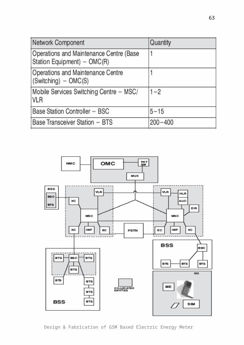
Fig 4.2: Pin Configuration of PIC 16F877A
4.4 - FEATURES:
4.4.1 - Special Microcontroller Features
Flash Memory: 14.3 Kbytes (8192 words)
Data SRAM: 368 bytes
Data EEPROM: 256 bytes
Self-reprogrammable under software control
In-Circuit Serial Programming via two pins (5V)
Watchdog Timer with on-chip RC oscillator
Programmable code protection
Power-saving Sleep mode
Selectable oscillator options
In-Circuit Debug via two pins
4.4.2 - Peripheral Features
33 I/O pins; 5 I/O ports
Timer0: 8-bit timer/counter with 8-bit prescaler
Timer1: 16-bit timer/counter with prescaler
o Can be incremented during Sleep via external crystal/clock
Timer2: 8-bit timer/counter with 8-bit period register, prescaler
and postscaler
Two Capture, Compare, PWM modules
o 16-bit Capture input; max resolution 12.5 ns
o 16-bit Compare; max resolution 200 ns
o 10-bit PWM
Synchronous Serial Port with two modes:
o SPI Master
o I2C Master and Slave
USART/SCI with 9-bit address detection
Parallel Slave Port (PSP)
Design & Fabrication of GSM Based Electric Energy Meter
63

o 8 bits wide with external RD, WR and CS controls
Brown-out detection circuitry for Brown-Out Reset
4.4.3 - Analog Features
10-bit, 8-channel A/D Converter
Brown-Out Reset
Analog Comparator module
o 2 analog comparators
o Programmable on-chip voltage reference module
o Programmable input multiplexing from device inputs and
internal VREF
o Comparator outputs are externally accessible.
CHAPTER NO.5
SOFTWARE TOOLSDesign & Fabrication of GSM Based Electric Energy Meter
64

Important Points:
Visual Basic
Microsoft Office Access
Crystal ReportIn order to achieve the goals we use many types of software. For PIC
microcontroller we used MPLAB and the complier was “picclite”. Bill
Calculation software is used for creating electricity bill for consumer;
Data is collected through automated meter reading after every 2
minutes. The programming tools which are used for creating this
software is Visual Basic and Microsoft Access. Visual Basic is not only
allowing programmer to create simple GUI (Graphical User Interface)
application, but can also develop fairly complex application as well.
5.1 – VISUAL BASIC:
Programming in Visual Basic is a combination of visually arranging
components or control on a form, specifying attributes and actions of
Design & Fabrication of GSM Based Electric Energy Meter
65

those components and writing additional line of code for more
functionality.
Visual Basic (VB) is an event driven programming language and
associated development environment from Microsoft for its COM
programming model. Visual Basic was derived from BASIC and enables
the rapid application development (RAD) of graphical user interface
(GUI) applications, access to databases using DAO, RDO, or ADO, and
creation of ActiveX controls and objects. Scripting languages such as
VBA and VB Script are syntactically similar to Visual Basic, but perform
differently.
Fig 5.1: Microsoft VB
A programmer can put together an application using the components
provided with Visual Basic itself. Programs written in Visual Basic can
also use the Windows API, but doing so requires external function
declarations.
5.1.1 - Language Features
Visual Basic was designed to be easy to learn and use. The language not
only allows programmers to create simple GUI applications, but can also
Design & Fabrication of GSM Based Electric Energy Meter
66

develop fairly complex applications as well. Programming in VB is a
combination of visually arranging components or controls on a form,
specifying attributes and actions of those components, and writing
additional lines of code for more functionality. Since default attributes
and actions are defined for the components, a simple program can be
created without the programmer having to write many lines of code.
Performance problems were experienced by earlier versions, but with
faster computers and native code compilation this has become less of an
issue.
Although programs can be compiled into native code executables from
version 5 onwards, they still require the presence of runtime libraries of
approximately 2 MB in size. This runtime is included by default in
Windows 2000 and later, but for earlier versions of Windows it must be
distributed together with the executable.
Forms are created using drag and drop techniques. A tool is used to
place controls (e.g., text boxes, buttons, etc.) on the form (window).
Controls have attributes and event handlers associated with them.
Default values are provided when the control is created, but may be
changed by the programmer. Many attribute values can be modified
during run time based on user actions or changes in the environment,
providing a dynamic application. For example, code can be inserted into
the form resize event handler to reposition a control so that it remains
centered on the form, expands to fill up the form, etc. By inserting code
into the event handler for a key press in a text box, the program can
automatically translate the case of the text being entered, or even
prevent certain characters from being inserted.
Visual Basic can create executables (EXE files), ActiveX controls, DLL
files, but is primarily used to develop Windows applications and to
interface web database systems. Dialog boxes with less functionality
(e.g., no maximize/minimize control) can be used to provide pop-up
capabilities. Controls provide the basic functionality of the application,
while programmers can insert additional logic within the appropriate
event handlers. For example, a drop-down combination box will
Design & Fabrication of GSM Based Electric Energy Meter
67

automatically display its list and allow the user to select any element. An
event handler is called when an item is selected, which can then execute
additional code created by the programmer to perform some action
based on which element was selected, such as populating a related list.
5.2 - MICROSOFT OFFICE ACCESS
Bill calculation software used Microsoft access for storing data. Microsoft
Access is a relational management system for Microsoft which
contributes the relational Microsoft jet database engine with a graphical
user interface (GUI) and software development tools.
Fig 5.2: Microsoft Office Access
5.2.1 – Features
One of the benefits of Access from a programmer's perspective is its
relative compatibility with SQL (structured query language) —queries
may be viewed and edited as SQL statements, and SQL statements can
be used directly in Macros and VBA Modules to manipulate Access
tables. In this case, "relatively compatible" means that SQL for Access
contains many quirks, and as a result, it has been dubbed "Bill's SQL" by
industry insiders. Users may mix and use both VBA and "Macros" for
programming forms and logic and offers object-oriented possibilities.
MSDE (Microsoft SQL Server Desktop Engine) 2000, a mini-version of
MS SQL Server 2000, is included with the developer edition of Office XP
Design & Fabrication of GSM Based Electric Energy Meter
68

and may be used with Access as an alternative to the Jet Database
Engine.
5.2.2 – Uses
Access is used by small businesses, within departments of large
corporations, and hobby programmers to create ad hoc customized
desktop systems for handling the creation and manipulation of data.
Access can be used as a database for basic web based applications
hosted on Microsoft's Internet Information Services and utilizing
Microsoft Active Server Pages ASP. Some professional application
developers use Access for rapid application development, especially for
the creation of prototypes and standalone applications that serve as tools
for on-the-road salesmen. Access does not scale well if data access is via
a network, so applications that are used by more than a handful of people
tend to rely on Client-Server based solutions. However, an Access "front
end" (the forms, reports, queries and VB code) can be used against a host
of database back ends, including JET (file-based database engine, used in
Access by default), Microsoft SQL Server, Oracle, and any other ODBC-
compliant product.
5.3 - CRYSTAL REPORT
Crystal Reports is a business intelligence application used to design and
generate reports from a wide range of data sources. Several other
applications, such as Microsoft Visual Studio, bundle an OEM version of
Crystal Reports as a general purpose reporting tool. Crystal Reports
became the defacto report writer when Microsoft released it with Visual
Basic.
5.3.1 - Creating reports
Users install Crystal Reports on a computer and use it to select specific
rows and columns from a table of compatible data (see "Supported data
sources" below). Users can then arrange the data on the report in the
format needed. Once the report layout is complete it is saved as a file
with the extension RPT. A report can be rerun anytime by reopening the
Design & Fabrication of GSM Based Electric Energy Meter
69

RPT file and 'refreshing' the data. If the source data has been updated
then the refreshed report will reflect those updates. The report can then
be previewed on the screen, printed onto paper or exported to one of
several different file formats such as PDF, Excel, text or CSV.
Report formats can vary from a simple column of values to layouts
featuring pie charts, bar charts, cross-tab summary tables and nested
sub reports. Crystal Reports is designed for "presentation quality"
reports so there are many options for enhanced formatting.
5.3.2 - Running reports locally
The users who design the reports can run them as needed from within
the report designer. When running reports directly within the report
designer the user has the ability to change any feature of the report. The
user can also create variations of the report by saving the modified RPT
file under another name.
It is also possible to run a Crystal Report without using the full Crystal
Reports designer software. These alternate methods for running reports
include locally installed viewers, schedulers, and report distribution
tools. These are typically third-party software programs (independent of
Business Objects) that allow you to open, refresh, preview, print and
export an RPT file. In 2007 Business Objects released their own viewer,
Crystal Reports Viewer XI, but unlike the independent viewers it does not
allow the user to refresh the report, only to view static data saved in the
RPT file.
Some of the independent viewers add other capabilities such as allowing
the user to schedule a report to run automatically at certain times. Still
others allow reports to be burst and /or distributed via Email.
Crystal report is bundled with a set of ActiveX controls that, when
embedded in a simple GUI, can provide an alternative user interface.
These same controls allow reports to be deconstructed into their base
objects. This, in turn, allows the same reports to be generated at run
time, customizing them as necessary.
Design & Fabrication of GSM Based Electric Energy Meter
70

Bill Calculation software used simple tools for developing this software.
CHAPTER NO.6
HARDWARE DETAILS
Design & Fabrication of GSM Based Electric Energy Meter
71

Important points:
Energy Meter
Optocoupler
Power Supply
LCD
6.0 - HARDWARE DETAILS
Implementation of the project was the most crucial and hectic phase of
the project. Day to day problems in the hardware circuitry adds fun to
the game. In order to implement the project following components are
used:
Meter
Microcontroller (PIC)
Opto coupler
Power supply
Transformer
LC circuit
LM 311 (Voltage Regulator)
Bridge Rectifier
LCD
Serial Port
Mobile
Some of the components have been discussed in detail in previous
chapters; the functionality of the rest is as follows:
6.1 - ANALOG ENERGY METER
Design & Fabrication of GSM Based Electric Energy Meter
72

6.1.1 - Overview:
An electric meter or an energy meter is a device that measures the
amount of electricity consumed by a residence or business. The most
common units of measurements for electricity in Pakistan are kilo watt-
hour. Therefore kilowatt-hour meters are widely used in Pakistan by
WAPDA. Utilities record the values read by these meters to generate
invoice for consumers. Although energy meters are of various types and
display reading in analog as well as in digital fashion, but WAPDA uses
analog electromechanical induction meters.
6.1.2 - Electromechanical Meters:
Electromechanical induction meters are widely used in Pakistan due to
their low price and good reading accuracy and long life. Their price
range is form Rs2000 to Rs3000. WAPDA uses meters made by PEL (PAK
ELEKTRON). The prototype is MC 8 single phase and TBL three phase
meter. All these meters are under license of ABB-USA.
MC8 Single Phase Meter
Parameters Values
Voltage 220-240V
Current (Nominal) 10, 20, 40A
Current (Maximum)
40, 60, 80, 100A
TBL Poly-Phase Meter
Parameters Values
Voltage 3x200/400V
Current (Nominal) 15A
Current (Maximum) 90A
6.1.3 - Technology:
Design & Fabrication of GSM Based Electric Energy Meter
73

The electromechanical induction meter operates by counting the
revolutions of an aluminum disc which is made to rotate at a speed
proportional to the power. The number of revolutions is thus proportional
to the energy usage. The rotating disc in this type of meter is, in fact, an
electric motor of a type called a reluctance motor or eddy current motor.
It consumes a small amount of power, typically around 2 watts.
The metallic disc is acted upon by two coils. One coil is connected in such
a way that it produces a magnetic flux in proportion to the voltage and
the other produces a magnetic flux in proportion to the current. This
produces eddy currents in the disc and the effect is such that a force is
exerted on the disc in proportion to the product of the instantaneous
current and voltage. A permanent magnet exerts an opposing force
proportional to the speed of rotation of the disc - this act as a brake
which causes the disc to stop spinning when power is drawn rather than
allowing it to spin faster and faster. This causes the disc to rotate at a
speed proportional to the power being used.
The type of meter described above is used on a single-phase AC supply.
Different phase configurations use additional voltage and current coils.
Design & Fabrication of GSM Based Electric Energy Meter
74

Fig 6.1: A typical energy meter
6.1.4 - Working:
The aluminum disc is supported by a spindle which has a worm gear
which drives the register. The register is a series of dials which record
the amount of power used. The dials may be of the cyclometer type
where for each dial a single digit is shown through a window in the face
of the meter, or of the pointer type where a pointer indicates each digit.
It should be noted that with the dial pointer type, adjacent pointers
generally rotate in opposite directions due to the gearing mechanism.
The amount of energy represented by one revolution of the disc is
denoted by the symbol KWH which is given in units of watt-hours per
revolution. The value 7.2 is commonly seen. Using the value of KWH, one
can determine their power consumption at any given time by timing the
disc with a stopwatch. If the time in seconds taken by the disc to
complete one revolution is t, then the power in watts is P = 3600×Kh/t.
For example, if KWH = 7.2, as above, and one revolution took place in
14.4 seconds, the power is 1800 watts. This method can be used to
determine the power consumption of household devices by switching
them on one by one.
Most domestic electricity meters must be read manually, whether by a
representative of the power company or by the customer. In Pakistan the
meter reading is mostly done by the representatives of Electric Supply
Company. They take the meter readings on monthly basis.
6.1.5 - Accuracy:
In an induction type meter, creep is a phenomenon that can adversely
affect accuracy that occur when the meter disc rotates continuously with
potential applied and the load terminals open circuited.
All the meters are first tested in WAPDA lab before installation to the
customer’s residence or business. In testing they check the disc
rotational speed. If it is not according to the company standard, it is
adjusted.
Design & Fabrication of GSM Based Electric Energy Meter
75

6.2 - OPTO COUPLER / OPTO ISOLATOR:
Opto coupler is basically used to transmit a signal from one end to the
other by the use of a short optical transmission path. In our particular
case an LED (photo diode) and a detector serves the purpose. The light
from the LED is blocked until the hole on the aluminum disc comes in
direct contact with LED; at this stage light from the LED is allowed to
pass through the hole and thus reaches the detector (transistor), which
on receiving the light pass an interrupt to the IC connected directly to it.
In this way the revolutions of the aluminum disc are counted and a digital
reading mechanism is established.
Fig 6.2: Opto coupler pin configuration
6.3 - POWER SUPPLY:
Power supply is used to operate the electronics components used in the
circuitry. Since such components cannot be directly connected to 220
volts, therefore the role of the power supply comes into contact. The
supply in this case is specially designed for the particular circuitry to
provide a voltage equal to 5 V, in order to operate IC and other related
components. The power supply is fitted with a step down transformer
which takes the voltage from power line prior to entering the meter, and
then it lowers the voltage to the desired value.
The hierarchy of the complete power supply goes as follows:
Design & Fabrication of GSM Based Electric Energy Meter
76

6.4 - LC CIRCUIT:
A specially designed LC circuit is placed right after the power supply
block in order to remove unwanted signal from the power supply block
that is, at deregulation of voltage there are some ripples and additive
noise that comes into action and may disrupt the whole function of the
circuit. This LC circuit is used to overcome such difficulties and thus
provide a noise free signal at the other end.
The capacitors used in this LC circuit play a vital role in the removal of
ripples made by the transformer and/or any other factor.
6.5 - VOLTAGE REGULATOR (LM 311):
Voltage regulator is used in order to prevent the IC from exposure to
high voltage typically in the range of 10-20V.Voltage regulator operates
at a certain range and has the capability of providing a fixed voltage at
on end no matter whatever the voltage occurs at the other end; provided
that it is in the range of voltage regulators’ specifications.
Design & Fabrication of GSM Based Electric Energy Meter
77
Voltage Source
Transformer
Regulator
LC Circuit
Load
Capacitor
Rectifier

The voltage regulator (LM 311) used in our case has the following
specifications:
Operates from single 5V supply
Input current: 150 nA max. over temperature
Offset current: 20 nA max. over temperature
Differential input voltage range: ±30V
Power consumption: 135 mW at ±15
Following is its parametric Table:
Response Time 0.1 us
Offset Voltage max, 25C 7.5 mV
Output Bus Open Drain
Supply Min 5 Volt
Supply Max 36 Volt
6.6 - LCD:
LCD is used to display the current (updated) and the previous reading of
the meter; it is updated at every increment of the unit. LCD is directly
connected to the PIC micro controller from a where a stream of numbers
is flushed into the LCD to display the readings of the meter.
CHAPTER NO.7
Design & Fabrication of GSM Based Electric Energy Meter
78
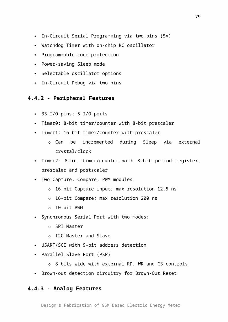
FUTURE ADVANCEMENTS IN PROJECT
Important Points
Duplex Communication Power Shut Down Data Storage Composite/Multi phases meter Networking
7.0 - FUTURE ADVANCEMENTS IN PROJECT
Luckily, we have achieved the goals of the project. During the project, we
faced a lot of problems while achieving the goals and it was really a very
tough job to do so. However due to wide scope in this domain a lot of
advancements can be made in this project. Due to time constraints and
the hardware problems, we were unable to work for advancement part
but we recommend our juniors to work on it. Following are the some
proposed advancements in my project.
Duplex Communication
Power Shut Down
Data Storage
Composite/Multi phases meter
Networking
Design & Fabrication of GSM Based Electric Energy Meter
79
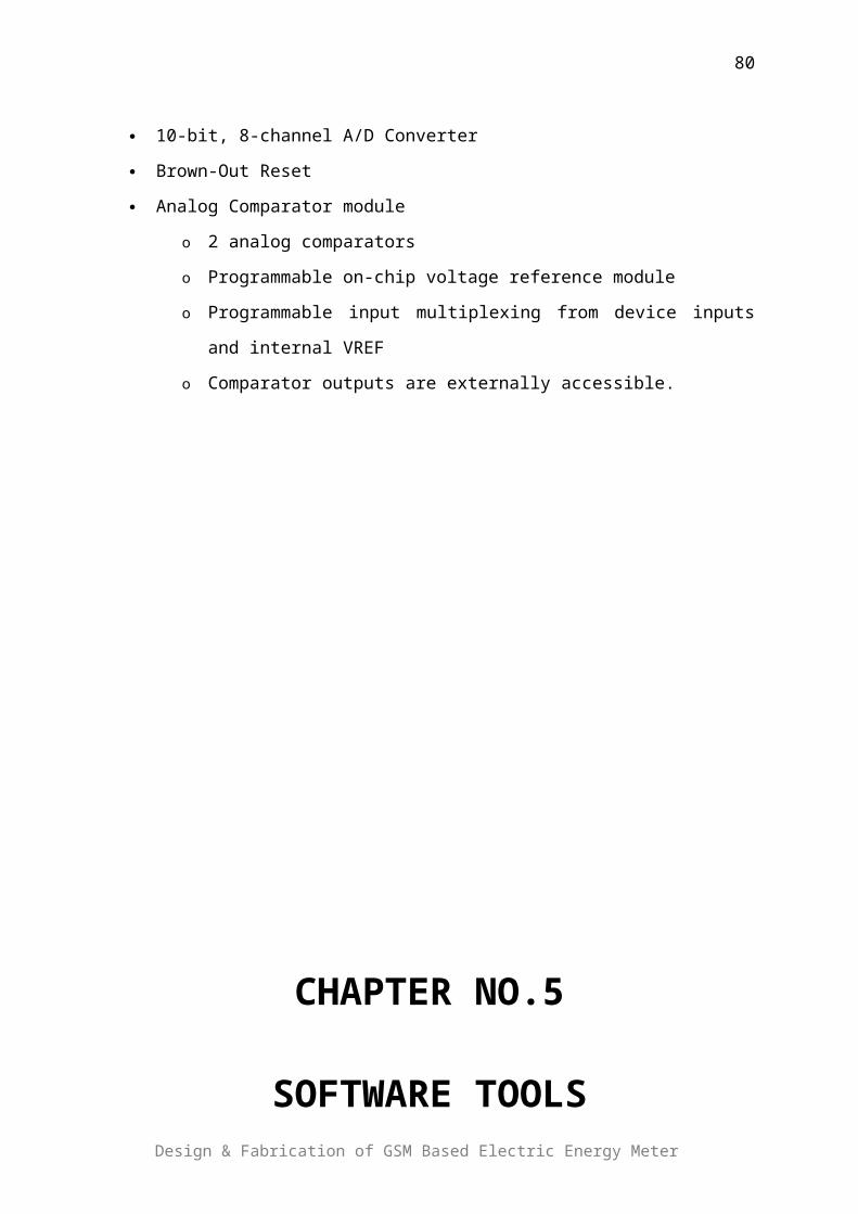
7.1 - DUPLEX COMMUNICATION:
The original project is based on the one way or single communication
system which handicap and close optional direction of server side. The
idea of improvisation of the communication system inherited for making
the project system more efficient. There can be duplex communication
instead of simplex communication. A simplex circuit is one where all
signals can flow in only one direction at a time. Examples are as follows:
Television broadcast
Commercial radio broadcast (not Citizens' band radio , etc.)
Internet multicast
A duplex communication system is a system composed of two connected
parties or devices which can communicate with one another in both
directions. The SMS can be sending when it is requested by the server
end. It can be half duplex or full duplex. A half-duplex system provides
for communication in both directions, but only one direction at a time
(not simultaneously) Example of a half-duplex system is walkie-talkie
style.
Fig 7.1: A simple illustration of a half-duplex communication system.
A full-duplex system allows communication in both directions, and unlike
half-duplex, allows this to happen simultaneously Examples: Telephone,
Mobile Phone, etc.
Design & Fabrication of GSM Based Electric Energy Meter
80

Fig 7.2: A simple illustration of a full-duplex communication system
It can save the memory and server can get information when required.
The problem with me for using duplex communication is I don’t have
registered version of compiler so I m unable to do duplex communication.
7.2 - POWER SHUT DOWN:
After improving the communication system to two way the path for the
advancement of the project opens. The option for shut down of power
supply can be exercised by devising and placing the relays with incoming
power circuit of energy meter which may operate after receiving the
directional signal from server end.
Fig 7.3: Showing meter dail
The multiple objectives can be achieved after the improvisation of the
system in energy meter besides the main objective of automated meter.
a) Power supply can be disconnected when required an occasion of
default of payment of electricity bill or any other reason.
b) A sensory devise can be installed at meter reading index or
sensitive area from where the functioning of meter can be
Design & Fabrication of GSM Based Electric Energy Meter
81
effected/stopped by anyone for unlaw purpose. This sensory devise,
or touch the sensitive area may pass signal to relay to auto shut
down the power supply. It will bring big change for effective
control of power theft and power supply of stealer can
automatically be shut down through system.
c) The unauthorized extension of load and its usage can be control
through fixing maximum load bearing capacity by sensory gadget.
The power supply can be shut down by tripping the gadget after
fixed load as the load beyond appeared load exceed, the relay
operates to shut the power supply.
7.3 - DATA STORAGE
The various data regarding electrical elements can be stored in the in
controller in meter for example
Meter reading based upon data or timing.
Load put on the system.
Voltage.
Power tripping record.
Fig 7.4: Showing reading in KWH
7.4 - COMPOSITE/MULTI PHASE METER:
The option for manufacturing the composite/multi phase meter cannot be
rejected. We may concentrate and put consideration for making a panel
Design & Fabrication of GSM Based Electric Energy Meter
82

meter which may have only one input which feed power at bus bar circuit
provided on meter and from where supply can be provided to various
output which contain its own meter reading register. There could be
facility of replacing one sub meter in a case of fault.
Fig 7.5: Meter Panel
The panel meter can provide clustering and jumping of cables and will
give beautiful look. The cost of meter can be reduced.
Fig 7.6: Meter Panel
7.5 - NETWORKING:
Design & Fabrication of GSM Based Electric Energy Meter
83
Network can be formed with the meters which are in the panel or are
vicinity of each other. An Ad-Hoc network can be formed for those meters
and by using single mobile phone/GSM chip and a single microcontroller
we can multiplex our data and sends the multiplexed reading the central
office. So instead of attaching a dedicated mobile phone and
microcontroller with every meter we can attach a single microcontroller
and mobile phone with many meters. In this way project on large scale
will be more cost effective.
APPENDIX I
#include<pic.h>
#include "firmlcd.h"
#define PORT PORTD
#define TRIS TRISD
unsigned long int TEnergy = 0;
unsigned long int TempTEnergy = 0;
unsigned char ascii_str[16];
const unsigned char meterid[] = {"ID: 00s000"};
const unsigned char at[5] = {'a','t','e','0',13};
const unsigned char ms[23] =
{'a','t','+','c','p','m','s','=','"','M','E','"',',','"','M','E','"',',','"','M','E','"',13};
const unsigned char gf[10] = {'a','t','+','c','m','g','f','=','1',13};
Design & Fabrication of GSM Based Electric Energy Meter
84
const unsigned char gs[22] =
{'a','t','+','c','m','g','s','=','"','0','3','2','1','4','1','7','1','3','2','1','"',13};
const unsigned char gr[10] = {'a','t','+','c','m','g','r','=','1',13};
const unsigned char gd[10] = {'a','t','+','c','m','g','d','=','1',13};
///////////////////////////////////////////////////////////////////////
void Main_init(void)
{
ADCON0=0;
ADCON1=7;
TRISB1=0;
RB1=0;
TRISB2=0;
RB2=0;
TRISB3=0;
RB3=0;
}
///////////////////////////////////////////////////////////////////
/*------------ Delay Function -------------*/
void delay(unsigned char x)
{
unsigned int i;
for(i=0;i<x*200;i++){}
}
///////////////////////////////////////////////////////////////////
/*------------LCD Char Function----------*/
//sends one character or number to the display for setup and messages
void lcd_write(const unsigned char data)
{
PORT = ((data/4) & 252);
PORT = (PORT | 2);
delay(1);
PORT = (PORT & 252);
Design & Fabrication of GSM Based Electric Energy Meter
85

PORT = ((4*data & 252) | 2);
delay(1);
PORT = (PORT & 252);
delay(2);
}
void lcd_mes(const unsigned char data1)
{
PORT = ((data1/4 & 252) | 1);
delay(1);
PORT = (PORT | 3);
delay(1);
PORT = (PORT & 253);
PORT = ((4*data1 & 252) | 3);
delay(1);
PORT = (PORT & 253);
delay(2);
PORT = (PORT & 252);
}
///////////////////////////////////////////////////////////////////
/*------------LCD Message Function--------*/
//sends a series of words to display by calling character
//function and checking the line number
void lcd_message (const unsigned char *ptr)
{
while(*ptr){
lcd_mes(*ptr++); //sendind string
}
}
///////////////////////////////////////////////////////////////////
/*------------- LCD INTEGER AND HEX FUNCTION ----------------*/
void lcd_int(unsigned long int_value)
Design & Fabrication of GSM Based Electric Energy Meter
86

{
unsigned char loop;
unsigned long remainder = 0;
for(loop=0;loop<11;loop++)
{
if(loop==1){
ascii_str[10 - loop++] = 46;
}
remainder = int_value % 10;
ascii_str[10-loop] = remainder + 48;
int_value = int_value / 10;
}
for(loop=0;loop<11;loop++){
lcd_mes(ascii_str[loop]); //sendind
string
}
ascii_str[11] = 32;
ascii_str[12] = 'k';
ascii_str[13] = 'W';
ascii_str[14] = 'h';
ascii_str[15] = 26;
}
/*------------------ LCD INITIALIZATION ------------------------ */
/////////////////////////////////////////////////////////////////////
void lcd_init(void) //initialises display to be on, clear etc
{
ADCON0=0X00; // A2D off
ADCON1=0X07; // A2D off
TRIS =0X00; // Data port init
PORT =0X08;
delay(180);
delay(45);
Design & Fabrication of GSM Based Electric Energy Meter
87

PORT=PORT + 2; //First initialization
delay(15);
PORT=0X08;
// delay(45);
// PORT=PORT + 2; //First initialization
// delay(15);
// PORT=0X08;
lcd_write (0x28); //set display, Data length 4-bit, 2-line,
5x8dots
lcd_write (0x0C); //Display on, cursor off, Blinking off
lcd_write (0x06); //Entry Mode Set, Increment Mode, Display
Shift off
}
void delay1(unsigned int del)
{
unsigned int k=0;
for(;del!=0;del--){
lcd_write(goto_2_1);
lcd_int(TEnergy/3);
for(k=0;k<200;k++);
}
}
void usart_init(void)
{
SPEN = 1;
TX9 = 0; //0 = Selects 8-bit transmission
SPBRG = 64;
BRGH = 1; //BRGH: High Baud Rate Select bit (1 = High
speed)
Design & Fabrication of GSM Based Electric Energy Meter
88

SYNC = 0; //SYNC: USART Mode Select bit (0 =
Asynchronous mode)
GIE=1;
}
void send(const unsigned char *cha, unsigned char no)
{
while(no!=0){
TXEN=1;
TXREG = *cha++;
delay1(1);
while(!TRMT);
TXEN=0;
no--;
}
}
unsigned int PICEEPROM_READ(unsigned int address)
{
EEPGD=0;
EEADR=address;
RD=1;
while(RD);
return EEDATA;
}
void PICEEPROM_WRITE(unsigned int address, unsigned int data)
{
EEPGD=0;
EEADR=address;
EEDATA=data;
WREN=1;
EECON2=0X55;
EECON2=0XAA;
WR=1;
Design & Fabrication of GSM Based Electric Energy Meter
89

while(WR);
WREN=0;
}
void main(void)
{
Main_init();
usart_init();
lcd_init();
lcd_write(1);
lcd_message(meterid);
TEnergy = PICEEPROM_READ(0)*16777216 +
PICEEPROM_READ(1)*65536 + PICEEPROM_READ(2)*256 +
PICEEPROM_READ(3);
lcd_write(goto_2_1);
lcd_int(TEnergy/3);
lcd_message(" kWh");
INTF=0;
INTE=1;
INTEDG=1;
delay1(5);
send(at,5);
delay1(5);
send(ms,23);
delay1(10);
send(gf,10);
delay1(10);
while(1){
// lcd_write(goto_2_1);
// lcd_int(TEnergy/3);
delay1(30);
RB2 = 1;
send(gd,10);
Design & Fabrication of GSM Based Electric Energy Meter
90

lcd_write(goto_2_1);
lcd_int(TEnergy/3);
delay1(20);
RB3 = 1;
send(gs,22);
delay1(1);
send(ascii_str,16);
RB2 = 0; RB3 = 0;
delay1(20);
}
}
static void interrupt inter (void)
{
if(INTF==1){
INTF = 0;
RB1 = !RB1;
TempTEnergy=TEnergy;
PICEEPROM_WRITE(0,TempTEnergy/16777216);
TempTEnergy=TempTEnergy%16777216;
PICEEPROM_WRITE(1,TempTEnergy/65536);
TempTEnergy=TempTEnergy%65536;
PICEEPROM_WRITE(2,TempTEnergy/256);
TempTEnergy=TempTEnergy%256;
PICEEPROM_WRITE(3,TempTEnergy);
TEnergy++;
}
}
Appendix II
Design & Fabrication of GSM Based Electric Energy Meter
91

Circuit Diagram
Appendix III
Design & Fabrication of GSM Based Electric Energy Meter
92

3.1 - BASIC CONCEPTS OF GSM
3.1.1 - Frequency Spectrum
The frequency spectrum is very congested, with only narrow slots of
bandwidth allocated for cellular communications.
A single Absolute Radio Frequency Channel Number (ARFCN) or RF
carrier is actually a pair of frequencies, one used in each direction
(transmit and receive). This allows information to be passed in both
directions. For each cell in a GSM network at least one ARFCN must be
allocated, and more may be allocated to provide greater capacity. The RF
carrier in GSM can support up to eight Time Division Multiple Access
(TDMA) timeslots. That is, in theory, each RF carrier is capable of
supporting up to eight simultaneous telephone calls, although this is
possible, network signaling and messaging may reduce the overall
number from eight timeslots per RF carrier to six or seven timeslots per
RF carrier, therefore reducing the number of mobiles that can be
supported.
Unlike a PSTN network, where every telephone is linked to the land
network by a pair of fixed wires, each MS only connects to the network
over the radio interface when required. Therefore, it is possible for a
single RF carrier to support many more mobile stations than its eight
TDMA timeslots would lead us to believe. Using statistics, it has been
found that a typical RF carrier can support up to 15, 20 or even 25 MSs.
Obviously, not all of these MS subscribers could make a call at the same
time, but it is also unlikely that all the MS subscribers would want to
make a call at the same time. Therefore, without knowing it, MSs share
the same physical resources, but at different times.
Design & Fabrication of GSM Based Electric Energy Meter
93

3.1.1.1 - Frequency Range
Receive(Uplin
k)
(MHz)
Transmit(Downlin
k)
(MHz)
Separation B\
W Uplink &
Downlink(MHz
)
ARFC
N
GSM 900 890-915 935-960 45 124
EGSM90
0
880-915 925-960 45 174
GSM180
0
1710-1785 1805-1880 95 374
PCS
1900
1850-1910 1930-1990 80 299
ARFCN= Absolute Radio Frequency Channel
ARFCN Bandwidth is 200 KHz and 8 TDMA Timeslots
3.1.2 - Cell Size
The number of cells in any geographic area is determined by the number
of MS subscribers who will be operating in that area, and the geographic
layout of the area (hills, lakes, buildings etc).
3.1.2.1 - Large Cells
The maximum cell size for GSM is approximately 70 km in diameter, but
this is dependent on the terrain the cell is covering and the power class
of the MS. In GSM, the MS can be transmitting anything up to 8 Watts;
obviously, the higher the power output of the MS the larger the cell size.
If the cell site is on top of a hill, with no obstructions for miles, then the
radio waves will travel much further than if the cell site was in the
Design & Fabrication of GSM Based Electric Energy Meter
94
middle of a city, with many high-rise buildings blocking the path of the
radio waves.
Generally large cells are employed in
Remote areas.
Coastal regions.
Areas with few subscribers.
Large areas which need to be covered with the minimum number of
cell sites.
3.1.2.2 - Small Cells
Small cells are used where there is a requirement to support a large
number of MS’s, in a small geographic region, or where a low
transmission power may be required to reduce the effects of
interference. Small cells currently cover 200 m and upwards.
Typical uses of small cells:
Urban areas.
Low transmission power required.
High number of MSs
3.1.2.3 - The Trade Off –Large vs. Small
There is no right answer when choosing the type of cell to use. Network
providers would like to use large cells to reduce installation and
maintenance cost, but realize that to provide a quality service to their
customers, they have to consider many factors, such as terrain,
transmission power required, number of MSs etc. This inevitably leads to
a mixture of both large and small cells.
The cells are normally drawn as hexagonal, but in practice they are
irregularly shaped, this is as a result of the influence of the surrounding
terrain, or of design by the network planners.
Design & Fabrication of GSM Based Electric Energy Meter
95
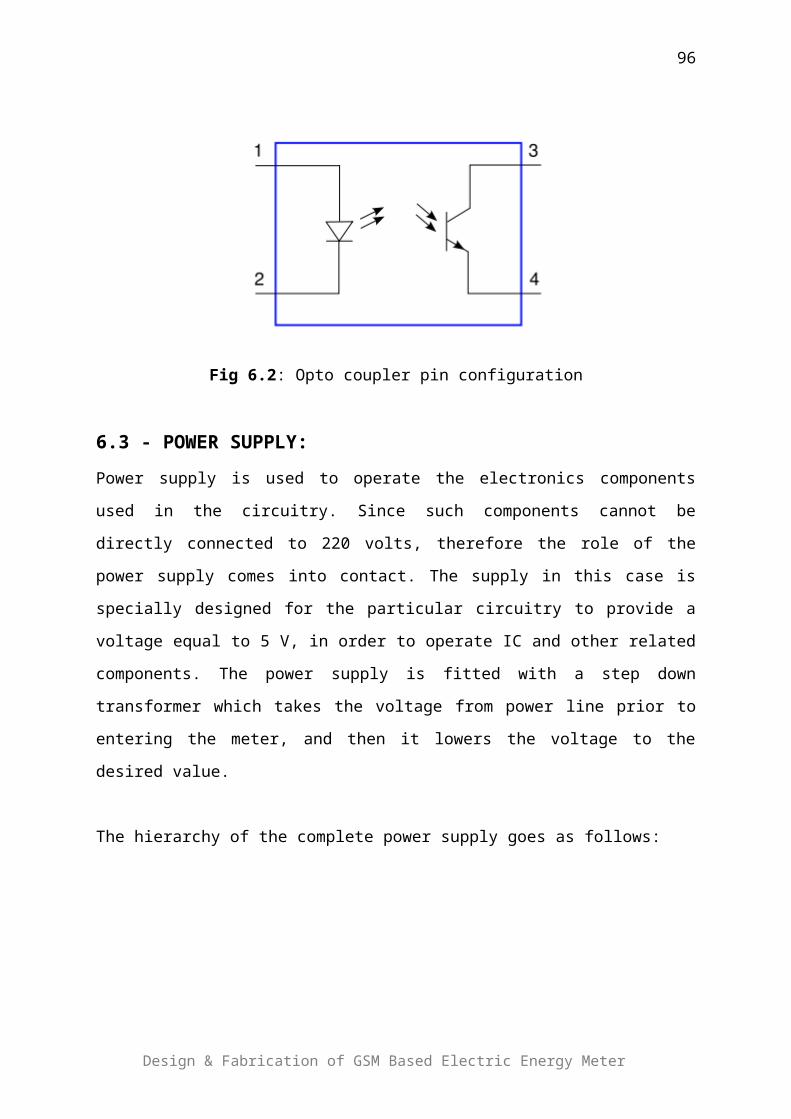
Fig 3.1: Showing large cells geometry
Fig 3.2: Showing large cells geometry
3.1.3 - Frequency re-use
Design & Fabrication of GSM Based Electric Energy Meter
96

Standard GSM has a total of 124 frequencies available for use in a
network. Most network providers are unlikely to be able to use all of
these frequencies and are generally allocated a small subset of the 124.
For instance a network provider has been allocated 48 frequencies to
provide coverage over a large area, let us take for example of England.
As we have already seen, the maximum cell size is approximately 70 km
in diameter, thus our 48 frequencies would not be able to cover the
whole of England. To overcome this limitation the network provider must
re-use the same frequencies over and over again, in what is termed a
“Frequency re-use pattern”. When planning the frequency re-use
pattern the network planner must take into account how often to use the
same frequencies and determine how close together the cells are,
otherwise co-channel and/or adjacent channel interference may
occur. The network provider will also take into account the nature of the
area to be covered. This may range from a densely populated city (high
frequency re-use, small cells, and high capacity) to a sparsely populated
rural expanse (large omni cells, low re-use, and low capacity).
Co-channel Interference
This occurs when RF carriers of the same frequency are
transmitting in close proximity to each other, the transmission from
one RF carrier interferes with the other RF carrier.
Adjacent Channel Interference
This occurs when an RF source of a nearby frequency interferes
with the RF carrier.
Design & Fabrication of GSM Based Electric Energy Meter
97

Fig 3.3: Showing frequency re-uses pattren
3.1.4 - Sectorization
The cells we have looked at up to now are called omni-directional cells.
That is each site has a single cell and that cell has a single transmit
antenna which radiates the radio waves to 360 degrees.
The problem with employing omni-directional cells is that as the number
of MS’s increases in the same geographical region, we have to increase
the number of cells to meet the demand. To do this, as we have seen, we
have to decrease the size of the cell and fit more cells into this
geographical area. Using omni-directional cells we can only go so far
before we start introducing co-channel and adjacent channel
interference, both of which degrade the cellular network’s performance.
To gain a further increase in capacity within the geographic area we can
employ a technique called “Sectorization”. A sectorization split a single
site into a number of cells, each cell has transmit and receive antennas
and behaves as an independent cell. Each cell uses special directional
antennas to ensure that the radio propagation from one cell is
concentrated in a particular direction.
Design & Fabrication of GSM Based Electric Energy Meter
98

3.1.4.1 - Advantages of sectorization
We are now concentrating all the energy from the cell in a smaller
area
60,120,180 degrees instead of 360 degrees, we get a much
stronger signal, which is beneficial in locations such as “in-
building coverage”.
Secondly, we can now use the same frequencies in a much closer
re-use pattern, thus allowing more cells in our geographic region
which allows us to support more MSs.
3.1.4.2 - Using Sectored Sites
The distribution of RF carriers, and the size of the cells, is selected to
achieve a balance between avoiding co-channel interference by
geographically separating cells using the same RF frequencies, and
achieving a channel density sufficient to satisfy the anticipated demand.
The diagram above illustrates how, by sectoring a site we can fit more
cells into the same geographical area, thus increasing the number of MS
subscribers who can gain access and use the cellular network. This
sectorization of sites typically occurs in densely populated areas, or
Design & Fabrication of GSM Based Electric Energy Meter
99

where a high demand of MS’s is anticipated, such as conference
centers/business premises.
Fig 3.4: showing different schemes of sectorization
3.1.4.3 - Site/3 Cell
A typical re-use pattern used in GSM planning is the 4 site/3 cell. For
example, the network provider has 36 frequencies available, and wishes
to use the 4 site/3 cell re-use pattern he may split the frequencies up as
follows:
Design & Fabrication of GSM Based Electric Energy Meter
100

In this configuration each cell has a total of 3 carriers and each site has a total of 9
carriers.
3.1.4.4 - 3 Site/3 Cell
As can be seen from the table, each cell now has 4 carriers and each site
has 12 carriers. This has the benefit of supporting more subscribers in
the same geographic region, but problems could arise with co-channel
and adjacent channel interference.
3.1.5 - Switching and Control
Design & Fabrication of GSM Based Electric Energy Meter
101

Having established radio coverage through the use of cells, omni-
directional and directional (sectored sites), now consider what happens
when the MS is in motion (as MS’s tend to be). At some point the MS will
have to move from one cell’s coverage area to another cell’s coverage
area. Handovers from one cell to another could be for
a number of reasons (e.g. the signal strength of the “serving cell” is less
than the signal strength of a “neighbor cell”, or the MS is suffering a
quality problem in the serving cell) and by handing over to one of its
neighbors this may stop the quality problem. Regardless of the reason for
a “handover” it has to be controlled by some entity, and in GSM that
entity is the Mobile services Switching Centre (MSC).
To perform a handover, the network must know which neighbor cell to
hand the MS over to. To ensure that we handover to the best possible
candidate the MS performs measurements of its surrounding neighbor
cells and reports its findings to the network. These are then analyzed
together with the measurements that the network performs and a
decision is made on a regular basis as to the need for a handover. If a
handover is required then the relevant signal protocols are established
and the handover is controlled by the MSC.
Handovers must be transparent to the MS subscriber. That is the
subscriber should be unaware that a handover has occurred. Some
networks may allow certain handovers to be performed at the BSS level.
This would be dependent on the manufacturer’s equipment.
ACRONYMS
Design & Fabrication of GSM Based Electric Energy Meter
102

A: ASP (Microsoft Active Server Pages) AMR (Automated Meter Reader)
B: BSS (Base Station System) BTS (Base Transceiver Station)
D: DTE (Data Terminal Equipment) DSP DAO
E: EIR (Equipment Identity Register) EC (Echo Canceller) EPROM (Erasable p EEPROM
F: FSR (File Select Register) FCC (Federal Communication Commision)
G: GUI (Graphical User Interface)
H: HLR (Home Location Register)
I: IWF (Interworking Function) INDR (Indirect Register) ISDN (Integrated Services Digital Network) ISP (Internet Service Provider) ITU (International Telecommunication Union)
Design & Fabrication of GSM Based Electric Energy Meter
103

L: LAN(Local Area Network)
M: MSISDN (Mobile Station International Service Network) MS (Mobile Station) MSC (Mobile Servicing Switching Center) MSRN (Mobile Station Roaming Network)
O: OMC(Operation and Maintenance Center)
P: PEL (Pak Electron Limited) PICs (Photonic Integrated Circuits) PWM (Pulse Width Modulation)
T: TRAU (Transcoder Rate Adoption Unit)
V: VLR (Visitor Location Register)
W: WAN (Wide Area Network)
References
Design & Fabrication of GSM Based Electric Energy Meter
104
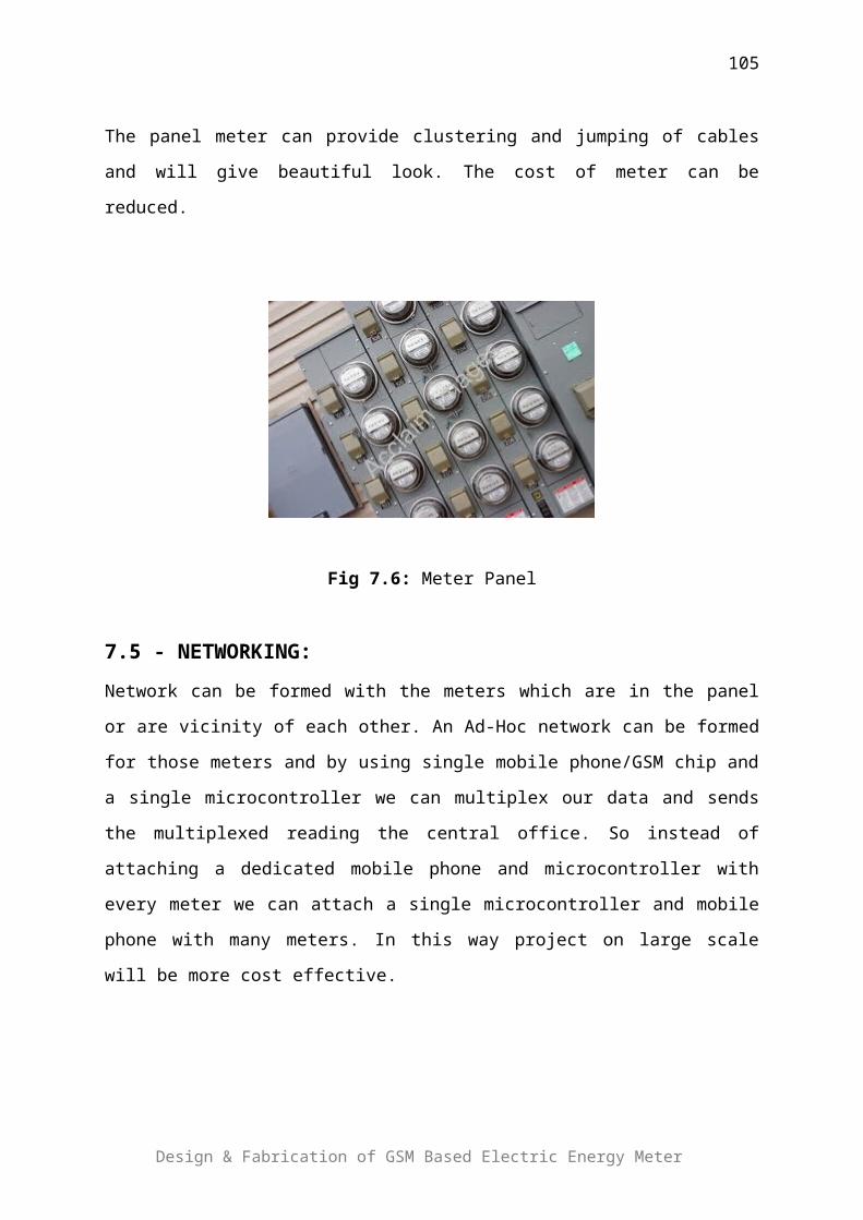
Websites
http://instruct1.cit.cornell.edu/courses/ee476/FinalProjects/
s2005/mpd25_yl293/476FinPrj/INDEX.HTM
www.novatelwireless.com/solutions/telemetry.html
http://www.active-robots.com/products/radio-solutions/radio-
communication.shtml
en.wikipedia.org/wiki/GSM
www.gsmworld.com
www.iec.org/online/tutorials/gsm/
en.wikipedia.org/wiki/PIC_microcontroller
www.microcontroller.com
crystal-reports-software.com
www.jaycar.com.au/images_uploaded/optocoup.pdf
Data Sheets:
www.national.com/pf/LM/LM317.html
www.sonyericsson.com/downloads/dg_at_2003_r4a.pdf
ww1.microchip.com/downloads/en/DeviceDoc/30292c.pdf
Books
The GSM System for Mobile Communications by Michel
Mouly, Marie-Bernadette Pautet
An Introduction to GSM by Siegmund H. Redl, Matthias K.
Weber, Malcolm W. Oliphant
The PIC Microcontroller - by John Morton
PIC Microcontroller Project Book - by John Iovine
Optoelectronics Circuits Manual - by Raymond Michael Marston
Modern Digital and Analog Communication Systems by B.P. Lathi
Wireless Communications by Theodore S. Rapaport
Design & Fabrication of GSM Based Electric Energy Meter
105

Design & Fabrication of GSM Based Electric Energy Meter
106


![Report - Project 1 [BCON2]](https://static.fdocuments.net/doc/165x107/55841d13d8b42aa15a8b4ae8/report-project-1-bcon2.jpg)


![Ccna Project Report[1]](https://static.fdocuments.net/doc/165x107/54fb15d94a795956048b5011/ccna-project-report1.jpg)

![Project Report[1] (1)](https://static.fdocuments.net/doc/165x107/577ce4c71a28abf1038f22f2/project-report1-1.jpg)


