REPORT OF RECONNAISSANCE LEVEL GEOTECHNICAL …
24
REPORT OF RECONNAISSANCE LEVEL GEOTECHNICAL EXPLORATION Pocotaligo Industrial Park Sumter County, South Carolina S&ME Project No. 1611-08-429 Prepared For: Alliance Consulting Engineers, Inc. PO Box 8147 Columbia, South Carolina 29202-8147 Prepared By: S&ME, Inc. 134 Suber Road Columbia, South Carolina 29210 October 15, 2008
Transcript of REPORT OF RECONNAISSANCE LEVEL GEOTECHNICAL …

REPORT OF RECONNAISSANCE LEVEL GEOTECHNICAL EXPLORATION
Pocotaligo Industrial Park
Sumter County, South Carolina S&ME Project No. 1611-08-429
Prepared For:
Alliance Consulting Engineers, Inc.
PO Box 8147 Columbia, South Carolina 29202-8147
Prepared By:
S&ME, Inc.
134 Suber Road Columbia, South Carolina 29210
October 15, 2008


Report of Reconnaissance Level Geotechnical Exploration S&ME Project No. 1611-08-429 Pocotaligo Industrial Park, Sumter County, SC October 15, 2008
PROJECT INFORMATION Information about the project was obtained through email correspondences between Mr. Tyke Redfearn with Alliance Consulting Engineers, Inc. and Marty Baltzegar of S&ME on September 2, 2008. A site location plan, topographic map, and aerial photograph of the subject property was included with the emails. The site is located in Sumter County, South Carolina (Figure 1) and consists of approximately 320 acres bordered on the east by US Highway 521, a creek to the north, the Pocotaligo River to the west, and an existing wastewater treatment plant to the south. The site is currently used for agricultural activities. Potential proposed construction would likely consist of light to medium industrial facilities and the associated parking and drive areas. Maximum column loads are expected to be less than 250 kips with wall loads of 3 to 4 kips per linear ft. Finished floor elevations are yet to be determined and will likely vary by building.
EXPLORATION PROCEDURES Prior to the subsurface exploration, aerial photos of the property and available topographic maps were reviewed to develop the proposed testing plan. On September 25, 2008, a representative of S&ME visited the site to perform the following tasks:
• Observe topography, ground cover, and surface soils in the proposed project area. • Lay out locations for seven soil test borings by rough measurement from site
features. Using an ATV-mounted rig, seven soil test borings were performed to depths of 30 feet each at the site. Total soil test boring footage at the site was 210 feet. Groundwater, if encountered, was measured at the time of boring and again at 24 hours after completion of drilling.
Subsurface Exploration The subsurface exploration of this project included Standard Penetration Test (SPT) borings. The methods used to perform these tasks are described below. The locations of each of the tests detailed below are shown in the attached Boring Location Plan (Figure 2). Soil Test Boring with Hollow-Stem Auger Soil sampling and penetration testing were performed in general accordance with ASTM D1586, “Standard Test Method for Penetration Test and Split Barrel Sampling of Soils”. Shallow borings are made by mechanically twisting a continuous steel hollow stem auger
1

Report of Reconnaissance Level Geotechnical Exploration S&ME Project No. 1611-08-429 Pocotaligo Industrial Park, Sumter County, SC October 15, 2008
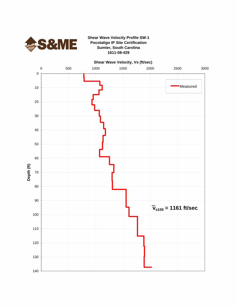
into the soil. At regular intervals, soil samples were obtained with a standard 1.4 inch I. D., two-inch O. D., split barrel sampler. The sampler was first seated six inches to penetrate any loose cuttings, and then driven an additional 12 inches with blows of a 140-pound hammer falling approximately 30 inches. The number of hammer blows required to drive the sampler through the two final six inch increments was recorded as the penetration resistance (SPT N) value. The N-value, when properly interpreted by qualified professional staff, is an index of the soil strength and foundation support capability. The soil test boring data is attached in the Appendix. Shear Wave Velocity Test Shear wave velocity measurements can be obtained using either shear wave surveys such as crosshole and downhole tests or surface wave surveys such as SASW, MASW, MAM, or ReMiTM. Analysis of surface waves (R-waves) can be used to determine shear-wave velocities (vs) as surface waves are fundamentally similar in behavior to shear waves (S-waves). In addition, the surface waves propagate to depths that are proportional to their frequencies (i.e., dispersion). The surface waves are recorded at the ground surface along a spread of low-frequency geophones. Recorded surface waves are transformed from time domain into frequency domain, from which the phase characteristics of the surface waves can be determined. A dispersion curve (a.k.a., phase velocity curve, slowness curve) is developed allowing the phase velocity (Cf) of particular frequency waves to be calculated. The dispersion curve is then transformed into the shear-wave velocity profile through a complex inversion and iterative processing. To measure shear-wave velocities at the subject site, S&ME performed MASW (Multi-Channel Analysis of Surface Waves) and MAM (Microtremor Array Method) with non-linear array geometry, combining the dispersion curves from both tests prior to the inversion process. Performing both MASW and MAM provides the greater depth of penetration associated with microtremor analyses (low frequency surface waves) without sacrificing resolution at shallower depths from MASW (higher frequency surface waves). In addition, our experience indicates using a combination of both methods to develop a shear wave velocity profile is more accurate than using Refraction Microtremor (ReMiTM) exclusively, particularly when the ReMiTM array geometry is linear. At each of the two test locations shown on the attached “Boring Location Plan,” MASW and MAM tests were performed to produce two separate shear wave velocity profiles at the site. The MASW and MAM testing was conducted using the 16-channel Geometrics ES3000 seismograph and 4.5 Hz vertical geophones. For the MASW testing, the geophones were spaced in a linear geometry at intervals of 6-feet and surface waves generated by both 2- and 10-pound sledgehammers striking a metal plate. MAM testing was conducted using an “L-shaped” array geometry with geophone spacing of 30 feet. Because the source locations of the microtremors are not known, the 2-dimensional array geometry is used for the MAM. The analysis was conducted using the OYO Corporation’s SeisImager/SW software (Pickwin v. 3.14 and WaveEq). The two separate velocity profiles developed at each of the test locations are attached.
2

Report of Reconnaissance Level Geotechnical Exploration S&ME Project No. 1611-08-429 Pocotaligo Industrial Park, Sumter County, SC October 15, 2008
SITE CONDITIONS
Surface Conditions The majority of the property is open fields with some wooded areas running along the northern and western boundaries of the property. The open fields are currently used as farmland with the western portion planted in soybeans. The wooded areas are mainly populated with second growth hardwoods. The site is nearly level and no standing water or rock outcrops were noted during our site visit.
Subsurface Conditions Site Geology The city of Sumter lies immediately southeast of a topographical feature termed the Citronelle Escarpment. The escarpment denotes the boundary between the upper and middle portions of the Atlantic Coastal Plain of South Carolina and is the major topographical feature of the coastal plain. The area northwest of the escarpment is termed the Santee Hills and is underlain by Tertiary age Coastal Plain residuum. Areas southeast of the escarpment, including downtown Sumter, lie within the Atlantic Flatwoods Region of the Lower Coastal Plain of South Carolina. The Atlantic Flatwoods comprises most of the Lower Coastal Plain, extending to the Surry Escarpment 15 to 40 miles inland from the sea. The topography of this region is dominated by up to six archaic marine terraces, exposed above sea level by uplifting of the local area over the last one million years. The terraces exhibit minor surface erosion, but can be traced large distances on the basis of surface elevation. Abandoned tidal eddies on the terraces have been filled with sediments and now form shallow, poorly drained elliptical depressions on the surface, termed Carolina bays, which are commonly apparent on aerial photographs or local topographic maps. Materials comprising the terraces typically consist of a strand or beach ridge deposit of clean sands at the seaward margin, interbedded with progressively more fine grained soils to the west. The marine terraces form a thin veneer over older, underlying Coastal Plain marl locally termed the Duplin Formation. Carolina bays are natural shallow depressions that are largely fed by rain and shallow groundwater. Bays in South Carolina are found on relict marine barrier beaches associated with Pleistocene sea level fluctuations, in dune fields, on stream terraces and sandy portions of backbarrier flats. No bays occur on modern river flood plains or beaches. Carolina Bays are elliptical and vary in size from approximately 200 feet to 7 miles. The bays display a marked alignment with northwest-southeast being the preferred orientation. Many bays have elevated sandy rims ranging up to 23 feet in height. Carolina bays occur only in unconsolidated sediments and are filled or partly filled with both organic and inorganic materials. Some bays contain lakes, some are boggy, others are either naturally or artificially drained and are farmed, and still others are naturally dry.
3

Report of Reconnaissance Level Geotechnical Exploration S&ME Project No. 1611-08-429 Pocotaligo Industrial Park, Sumter County, SC October 15, 2008
USDA Soil Survey Information USDA Soils Conservation Service soils mapping for Sumter County indicate predominantly Norfolk loamy sand series to be located within the site with several other soil series also present. Included in these are the Rembert loam series that are found in Carolina Bays and are located in three distinct areas on the site. Soil map units are also described in terms of some relevant engineering properties or in terms of relative suitability for use in land development. A description of the soils series mapped within the proposed site is summarized in Table 1.
Table 1 – USDA Soil Survey Soil Series
Soil Series Soil Type
Depth to Seasonal High
GW Table Permeability Remarks
Norfolk loamy sand
(NoA, NoB)
SM, SC, CL 4 - 6 ft. Moderate
Nearly level to gently sloping, deep, well drained soils formed in loamy Coastal
Plain sediment.
Rains sandy loam (Ra)
SM, SC, CL 0 - 1 ft. Moderate Nearly level, poorly drained soils formed
in loamy Coastal Plain sediment.
Rutlege loamy sand (Ru)
SM, SP-SM 0 - 1 ft. Rapid (impeded
by high water) Nearly level, very poorly drained, sandy
soils.
Rembert loam (Rm)
ML-CL, CL,
SC, SM 0 - 1 ft. Slow
Nearly level, moderately deep, poorly drained soils formed in clayey and sandy Coastal Plain sediment. In oval-shaped depressions known as Carolina Bays.
Lynchburg sandy loam
(Ly)
SM, CL, SC 1 - 2 ft. Moderate
Nearly level, deep, somewhat poorly drained soils formed in loamy Coastal
Plain sediment.
Goldsboro loamy sand
(Go)
SM, SC, CL 1.5 – 2.5 ft. Moderate
Nearly level, deep, moderately well drained soils formed in loamy Coastal
Plain sediment.
Wagram sand (WgB)
SM, SP-SM, SC
> 6 ft. Slow to Moderate
Nearly level to strongly sloping, deep, well drained soils formed in loamy Coastal
Plain sediment.
The seasonal high groundwater table as indicated by the Soil Survey is higher than the groundwater measurements made during our subsurface exploration. However, based on the borings conducted, the potential exists for perched water on this site during periods of normal or above normal rainfall. Interpreted Subsurface Profile The generalized subsurface conditions at the site are described below. Subsurface conditions between the borings will likely vary. The nature and extent of variations between the sampling points will not become evident until construction, and stratification lines shown are not warranted. For detailed descriptions and stratification at a particular boring location, the respective boring record should be reviewed. Soil test boring logs are attached in the Appendix.
4

Report of Reconnaissance Level Geotechnical Exploration S&ME Project No. 1611-08-429 Pocotaligo Industrial Park, Sumter County, SC October 15, 2008
Surface Soils Topsoil thicknesses encountered at our boring locations were typically 2 inches or less. However, our borings were conducted mostly along travel ways within the site and topsoil thicknesses will likely be greater in areas not explored by our borings. Organic plow zone material is likely present across much of site since the primary use of the property has been for farming. Plow zone depths can typically range from 6 to 12 inches in depth, though they may be greater. Subsurface Soils Below the topsoil, with the exception of borings B-2 and B-7, our borings generally encountered firm to very hard sandy clays to depths of between 6 and 13 feet. These soils exhibited SPT N-values ranging from 6 to 81 blows per foot (bpf) and were brown, orange, red, gray or a combination these colors. The sandy clays were typically moist and exhibited low to moderate plasticity when manipulated by hand. In borings B-2 and B-7, loose to dense clayey sands were encountered below the topsoil and above the sandy clays to depths of between 3 and 8 feet. These soils were moist, exhibited SPT N-values ranging from 6 to 33 blows per foot (bpf), and were brown, orange, or gray in color. The sandy clays were underlain by loose to very dense sands with clay, clayey sands, and silty sands to depths of between 28 feet and termination of the borings at 30 feet. These soils exhibited SPT N-values ranging from 8 to 57 blows per foot (bpf), were moist to saturated, and were brown, orange, red, gray, tan or a combination these colors. Boring B-3 encountered firm to stiff clay and sandy clay within this layer between about 13 and 23 feet and boring B-5 encountered very stiff sandy clay between about 23 and 28 feet. Below the sands with clay, clayey sands and silty sands, borings B-1 and B-2 encountered stiff to very stiff sandy clays to termination of the borings at 30 feet. These soils exhibited SPT N-values ranging from 14 to 18 blows per foot (bpf) and were brown or brown and gray in color. The sandy clays were typically moist and exhibited low plasticity when manipulated by hand. Groundwater Groundwater was encountered in our borings between 12.2 and 23.5 feet below the ground surface at the time of boring and between 9 and 21.4 feet when remeasured 24 hours after the borings were terminated. Our exploration was conducted during an extended period of drought. Groundwater elevations may be significantly higher during periods of more normal rainfall. Medium dense clayey sands or very stiff fine grained soils were encountered within the upper 5 feet of our borings. These soils will likely limit rain water infiltration and perched groundwater is likely during periods of normal or above normal rainfall.
5
Report of Reconnaissance Level Geotechnical Exploration S&ME Project No. 1611-08-429 Pocotaligo Industrial Park, Sumter County, SC October 15, 2008
SEISMIC CONSIDERATIONS Seismic induced ground shaking at the foundation is the effect taken into account by seismic-resistant design provisions of the 2006 International Building Code (IBC). Other effects, including soil liquefaction, are not addressed in building codes but must also be considered.
IBC Site Class This site has been classified according to one of the Site Classes defined in IBC Section 1613.5 (Table 1613.5.2) using the procedures described in Section 1613.5.5.1. The Site Class is used in conjunction with mapped spectral accelerations SS and S1 to determine Site Coefficients FA and FV in IBC Section 1613.5.3, tables 1613.5.3(1) and 1613.5.3(2). The initial step in site class definition is a check for the four conditions described for Site Class F which would require a site specific evaluation to determine site coefficients FA and FV. Soils vulnerable to potential failure under item 1) including quick and highly sensitive clays or collapsible weakly cemented soils, were not observed in the soundings. Three other conditions, 2) peats and highly organic clays; 3) very high plasticity clays; and 4) very thick soft/medium stiff clays, were also not evident in the soundings performed. Liquefaction appears unlikely at this site due to the fines content of the soils encountered, the recorded shear wave velocities, and the relatively high SPT N-values recorded in the borings in the upper 40 feet. We then compared site conditions to the three conditions described for Site Class E. These are soft soils vulnerable to large strains under seismic motion. Borings did not include at least 10 feet having 1) plasticity index greater than 20, 2) moisture content greater than 40 percent, and 3) undrained shear strength less than 500 psf. The site was then categorized using the method described in section 1613.5.5.1, paragraph 3.1 (VS method) for a 100 foot depth below the site. Shear wave velocities were measured using MASW (Multi-Channel Analysis of Surface Waves) methods. Average shear wave velocities of 1078 ft/s and 1161 ft/s were obtained in the two MASW arrays. Based on the soil test boring data, shear wave velocity data and knowledge of the general geologic profile of this area, Site Class D appears to generally represent conditions in and around the site.
Design Spectral Values S&ME determined the spectral response parameters for the site using the general procedures outlined under the 2006 International Building Code Section 1613.5. This approach utilizes a mapped acceleration response spectrum corresponding to an earthquake having a 2 percent statistical probability of exceedance in 50 years to determine the spectral response acceleration at the top of seismic bedrock for any period.
6

Report of Reconnaissance Level Geotechnical Exploration S&ME Project No. 1611-08-429 Pocotaligo Industrial Park, Sumter County, SC October 15, 2008
The 2006 International Building Code seismic provisions of Section 1613 use the 2002 Seismic Hazard Maps published by the National Earthquake Hazard Reduction Program (NEHRP) to define the base rock motion spectra. The 2002 seismic hazard maps used in Section 1613 of the 2006 IBC have been updated several times since their original publication, reflecting updated knowledge of the probabilistic hazard in different parts of the country as well as advances in the understanding of seismic wave propagation and damping through the various soil and rock strata. As of July 1, 2008, the USGS 2002 updated gridded spectral values in computation of the bedrock spectral response at this site may be used. The Site Class is used in conjunction with mapped spectral accelerations SS and S1 to determine Site Coefficients FA and FV in IBC Section 1613.5.3, tables 1613.5.3(1) and 1613.5.3(2). For purposes of computation, the Code includes mapped induced acceleration at frequencies of 5 hertz (SS) and 1 hertz (S1), which are then used to derive the remainder of the response spectra at all other frequencies. Mapped SS and S1 values represent motion at the top of bedrock. The surface ground motion response spectrum, accounting for inertial effects within the soil column overlying rock, is then determined for the design earthquake using spectral coefficients FA and FV for the appropriate Site Class. The design ground motion at any period is taken as 2/3 of the smoothed spectral acceleration as allowed in section 1613.5.4. The design spectral response acceleration values at short periods SDS and at one second periods SD1 are tabulated below for the unimproved soil profile. Peak ground acceleration (PGA) was obtained by dividing the SDS value by 2.5.
Table 2 – Design Spectral Values
Value 2002 Seismic Hazard Maps
SDS 0.64 g
SD1 0.28 g
PGA 0.26 g
For a structure having a Seismic Use Group classification of I or II, the SDS and SD1 values obtained from the 2006 IBC (2002 Seismic Hazard Maps) are consistent with Seismic Design Category D as defined in section 1613.6.
CONCLUSIONS AND RECOMMENDATIONS The conclusions and recommendations included in this section are based on the data obtained during our exploration. The following recommendations are given only to present a general idea of the soil conditions that may be anticipated at the site. More in-depth
7

Report of Reconnaissance Level Geotechnical Exploration S&ME Project No. 1611-08-429 Pocotaligo Industrial Park, Sumter County, SC October 15, 2008
subsurface investigations should be performed in future building pads and parking areas. We recommend that S&ME be retained to perform these additional subsurface explorations.
Site Preparation and Earthwork Stripping depths will likely be about 6 to 12 inches over the majority of the site. Our borings generally encountered topsoil depths of two inches or less. This is likely because they were located mainly within travel ways on the site. In drainage features, stripping depths may be considerably greater. We recommend conducting organic content tests within the building and pavement footprints. Organically stained soils with organic contents of 3 percent or less may be left in place but may need stabilization (compaction). Detention/retention ponds may be constructed to provide borrow material for site construction. The clayey and silty sands encountered in our soil test borings appear suitable for use as structural fill. However, sands containing high fines contents may be difficult to work if allowed to become wet and could require extensive drying. The sandy clays encountered in our borings are not recommended for reuse as structural fill.
Foundations The soil profiles encountered appear generally suitable for development for industrial use considering static loading. The use of shallow foundations for support of column loads up to 250 kips appears feasible for typical light to medium industrial structural column configurations, provided footings are properly constructed and settlements of about 1 inch can be tolerated. Area loads imposed by stacked materials or large vessels or tanks can likely be supported by mat or strip footings, provided that several inches of settlement can be withstood by the structure. Once building locations are established, borings should be conducted within each building footprint prior to design of foundations.
Control of Groundwater and Surface Runoff Groundwater was encountered between 9 to 23.5 feet in our borings; however, very stiff to hard fine grained soils and medium dense to dense clayey sands similar to those encountered in the upper 5 to 10 feet of the soil profile may inhibit downward infiltration of rainfall, and formation of a perched water table at relatively shallow depths is possible during wet periods. If perched water or groundwater is encountered during grading, ditching will be necessary to provide a stable bearing surface for foundations or pavements. In areas were machine pits may be constructed, ditching, well points or excavation of sumps and pumping may be necessary to sufficiently lower groundwater levels for construction of foundations. Capacity of sediment or detention ponds may also be limited in areas where shallow groundwater is encountered.
8
Report of Reconnaissance Level Geotechnical Exploration S&ME Project No. 1611-08-429 Pocotaligo Industrial Park, Sumter County, SC October 15, 2008
During normal rainfall periods, ditching or other provisions for drainage should be provided prior to stripping and grading in low areas. If subsurface water or infiltrating surface water is not properly controlled during construction, the subgrade soils that will support foundations, as well as pavements or floor slabs, may be damaged. Furthermore, construction equipment mobility may be impaired.
Grade Slab Support and Construction It is likely that grade slabs will be supported by virgin on-site soils or on-site borrow soils. 1 The clayey sands and sandy clays similar to those penetrated by our borings will
generally provide adequate support to soil-supported slabs-on-grade, assuming proper preparation, moisture control, and compaction of the subgrade for static load conditions.
2 A capillary break of at least 4 inches of clean sand or crushed stone placed below floor
slabs will be required. 3 We recommend you place a vapor barrier such as "Visqueen," or the equivalent, to
limit moisture infiltration into finished space, or other areas where moisture infiltration will potentially cause problems. The vapor barrier should be placed below the capillary break material.
Pavement Subgrade and Base Material Preparation The clayey sands encountered in the soil test borings will provide adequate bearing for pavements after being improved by drainage, rolling and compaction. However, the clayey sands may be difficult to work if allowed to become wet and will not provide good bearing if proper moisture control is not used. The sandy clays in our borings are less desirable for support of pavement sections but can be successfully used with proper construction practices. Drainage of subgrade material plays an important role in the performance of pavement sections. Site preparation should allow for drainage that results in groundwater elevations being maintained at least 2 ft. below the top of the pavement section. At least one laboratory California Bearing Ratio (CBR) test should be performed upon representative soil samples of each soil type, which is proposed for use as subgrade material. This is to establish the relationship between relative compaction and CBR for the soil in question. This will also confirm that the CBR value of the soils used at the required level of compaction is equal to or greater than the CBR value assumed during design of the pavement section.
Recommendations for Additional Exploration
9

Report of Reconnaissance Level Geotechnical Exploration S&ME Project No. 1611-08-429 Pocotaligo Industrial Park, Sumter County, SC October 15, 2008
The current number of borings provides some indication of the range of conditions that may be encountered at the site. However, the spacing and number of borings does not provide a reliable basis for design of building foundations. Once building, possible railway, parking and access drive locations are decided, we recommend additional soil test borings or cone penetration test soundings be performed in the proposed footprints.
QUALIFICATIONS OF REPORT This report has been prepared in accordance with generally accepted geotechnical engineering practice for specific application to this project. The conclusions and recommendations contained in this report were based on the applicable standards of our profession at the time this report was prepared. No other warranty, express or implied, is made. Due to the distance between each sounding, subsurface conditions can be expected to vary from the conditions described herein. This report was intended to give general information about overall site conditions only. Additional geotechnical explorations should be conducted for each proposed structure, railway, pavement area or roadway. Under Section 1705 of the International Building Code, a formal Quality Assurance Plan is required for most structures described as Seismic Design Category D as defined in Section 1616. While some of the Special Inspection required under sections 1706-1713 involve soils or foundations, preparation of the Quality Assurance Plan was beyond the scope of this preliminary report.
10

SOURCE: MAPQUEST 2008SCALE: NTS SITE LOCATION MAP FIGURE NO:
CHECKED BY: JTP POCOTALIGO INDUSTRIAL PARKDRAWN BY: TH SUMTER COUNTY, SOUTH CAROLINADATE: 10/15/08 JOB NO. 1611-08-429 1
SITE
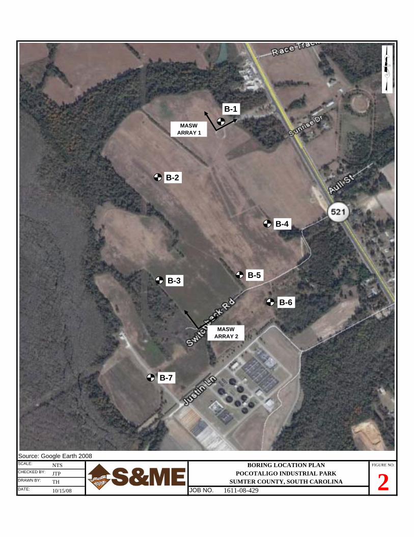
Source: Google Earth 2008SCALE: NTS BORING LOCATION PLAN FIGURE NO:
CHECKED BY: JTP POCOTALIGO INDUSTRIAL PARKDRAWN BY: TH SUMTER COUNTY, SOUTH CAROLINADATE: 10/15/08 JOB NO. 1611-08-429 2
B-1
B-2
B-3
B-4
B-5
B-6
B-7
MASWARRAY 2
MASWARRAY 1
Shear Wave Velocity Profile SW-1Pocotaligo IP Site Certification
Sumter, South Carolina1611-08-429
0
10
20
30
40
50
60
70
80
90
100
110
120
130
140
0 500 1000 1500 2000 2500 3000
Shear Wave Velocity, Vs (ft/sec)
Dep
th (f
t)
Measured
vs100 = 1161 ft/sec

Shear Wave Velocity Profile SW-2Pocotaligo IP Site Certification
Sumter, South Carolina1611-08-429
0
10
20
30
40
50
60
70
80
90
100
110
0 500 1000 1500 2000 2500 3000
Shear Wave Velocity, Vs (ft/sec)
Dep
th (f
t)
Measured
vs100 = 1078 ft/sec

WATER LEVELS
REC
Very LooseLoose
Medium DenseDense
Very Dense
Rock
Incompetent Rock
Boulder
Partially WeatheredRock (PWR)
CONSISTENCY OF COHESIVE SOILS
CONSISTENCY
STD. PENETRATIONRESISTANCEBLOWS/FOOT
Very SoftSoftFirmStiff
Very StiffHard
Very Hard
SAMPLER TYPES(Shown in Samples Column)
TERMS
StandardPenetrationResistance
Sandy Clay
(Shown in Graphic Log)
RELATIVE DENSITY0 to 4
5 to 1011 to 3031 to 50Over 50Clay
SOIL TYPES
HC
Silt
Shelby Tube
Split Spoon
Rock Core
No Recovery
Silty Sand
Clayey Sand
Gravel
Sandy Silt
Topsoil
LEGEND TO SOIL CLASSIFICATION AND SYMBOLS
(Shown in Water Level Column)
- Total Length of Rock Recovered in the CoreBarrel Divided by the Total Length of the Core RunTimes 100%.
- Total Length of Sound Rock Segments Recoveredthat are Longer Than or Equal to 4" (mechanicalbreaks excluded) Divided by the Total Length ofthe Core Run Times 100%.
0 to 23 to 45 to 8
9 to 1516 to 3031 to 50Over 50
Organic
STD. PENETRATIONRESISTANCEBLOWS/FOOT
RELATIVE DENSITY OF COHESIONLESS SOILS
= Water Level At Termination of Boring= Water Level Taken After 24 Hours= Loss of Drilling Water= Hole Cave
Sand
- The Number of Blows of 140 lb. Hammer Falling30 in. Required to Drive 1.4 in. I.D. Split SpoonSampler 1 Foot. As Specified in ASTM D-1586.
Fill
RQD
Asphalt
Concrete

CLAYEY SAND (SC) - mostly fine to medium sands, some lowplasticity fines, moist to wet, light brown, orange, very dense tomedium dense.
14
TOPSOIL - approximately 2 inches of topsoil.
SANDY LEAN CLAY (CL) - mostly low plasticity fines, some finesands, moist, brown, firm to very hard.
BO
RIN
G L
OG
08-
429L
OG
S.G
PJ
WIT
H C
PT.
GD
T 1
0/15
/08
- increase fine sands.
55
- brown, orange, tan.
- yellowish brown.
SANDY LEAN CLAY (CL) - mostly low plasticity fines, some fineto meidum sands, trace coarse sands, moist, dark brown, stiff.
BORING TERMINATED AT 30 FEET.
BORING LOG
- low to medium plasticity fines, moist, brown, orange, gray.
21
17
1
2
3
4
5
6
7
8
6
20
81
62W
ATE
R L
EV
EL
30
DRILL RIG:
WATER LEVEL:
80
N V
ALU
E
DE
PTH
(feet
)
SA
MP
LE N
O.
SA
MP
LE T
YP
E
23.5' @ TOB; 21.2' @ 24 hrs.
5
10
15
20
25
30
9/30/2008
2¼" H.S.A.
WMJ
S&ME - Spartanburg
PROJECT: Pocotaligo Industrial ParkSumter County, South Carolina1611-08-429
Page 1 of 1NOTES:
1.
2.
3.
4.
MATERIAL DESCRIPTION
THIS LOG IS ONLY A PORTION OF A REPORT PREPARED FOR THE NAMEDPROJECT AND MUST ONLY BE USED TOGETHER WITH THAT REPORT.
BORING, SAMPLING AND PENETRATION TEST DATA IN GENERAL ACCORDANCEWITH ASTM D-1586.
STRATIFICATION AND GROUNDWATER DEPTHS ARE NOT EXACT.
WATER LEVEL IS AT TIME OF EXPLORATION AND WILL VARY.
GR
AP
HIC
LOG
30 60
NOTES:DATE DRILLED:
DRILLING METHOD:
LOGGED BY:
DRILLER:
10
ELEVATION:
BORING DEPTH:
Mobile B-57
B-1
20
STANDARD PENETRATION TEST DATA(blows/ft)
ELE
VA
TIO
N(fe
et-M
SL)

CLAYEY SAND (SC) - mostly fine to medium sands, some lowplasticity fines, moist, reddish brown, gray, tan, dense.
18
TOPSOIL - approximately 2 inches of topsoil.
CLAYEY SAND (SC) - mostly fine sands, some low plasticityfines, moist, light brown, loose.
15
BO
RIN
G L
OG
08-
429L
OG
S.G
PJ
WIT
H C
PT.
GD
T 1
0/15
/08
SANDY LEAN CLAY (CL) - mostly low to medium plasticity fines,some fine sands, moist, brown, reddish brown, trace gray, very stiffto hard.
- mostly medium plasticity fines, moist, gray, trace brown.
BORING TERMINATED AT 30 FEET.
SANDY LEAN CLAY (CL) - mostly low plasticity fines, some finesands, moist, brown, gray, very stiff.
POORLY GRADED SAND WITH CLAY (SP-SC) - mostly fine tocoarse sands, few low plasticity fines, wet, light tan, gray, mediumdense.
- some low plasticity fines, saturated, light tan, white.
SILTY SAND (SM) - mostly fine sands, some low to mediumplasticity fines, moist, reddish brown, yellowish brown, gray,medium dense.
11
17
5
32
33
19
6
8
6
4
3
2
1
7
WA
TER
LE
VE
L
80
30
DRILL RIG:
WATER LEVEL:
ELE
VA
TIO
N(fe
et-M
SL)
PROJECT: Pocotaligo Industrial ParkSumter County, South Carolina1611-08-429
10/1/2008
2¼" H.S.A.
WMJ
S&ME - Spartanburg
5
10
15
20
25
30
16' @ TOB
DE
PTH
(feet
)
N V
ALU
E
SA
MP
LE N
O.
SA
MP
LE T
YP
E
30
THIS LOG IS ONLY A PORTION OF A REPORT PREPARED FOR THE NAMEDPROJECT AND MUST ONLY BE USED TOGETHER WITH THAT REPORT.
BORING, SAMPLING AND PENETRATION TEST DATA IN GENERAL ACCORDANCEWITH ASTM D-1586.
STRATIFICATION AND GROUNDWATER DEPTHS ARE NOT EXACT.
WATER LEVEL IS AT TIME OF EXPLORATION AND WILL VARY.
1.
2.
3.
4.
NOTES:
STANDARD PENETRATION TEST DATA(blows/ft)
Page 1 of 1
GR
AP
HIC
LOG MATERIAL DESCRIPTION
BORING LOG
20
B-2
Mobile B-57
ELEVATION:
BORING DEPTH:
10
DATE DRILLED:
DRILLING METHOD:
LOGGED BY:
DRILLER:
NOTES:
60

- brown, reddish orange, gray.
50/5"
57
>>
BORING TERMINATED AT 30 FEET.
BO
RIN
G L
OG
08-
429L
OG
S.G
PJ
WIT
H C
PT.
GD
T 1
0/15
/08
TOPSOIL - approximately 2 inches of topsoil.
SANDY LEAN CLAY (CL) - mostly low to medium plasticity fines,some fine to medium sands, moist, gray, brown, reddish/brown,firm to hard.
SILTY SAND (SM) - mostly fine sands, some low plasticity fines,slightly micaceous, moist, gray, brown, very dense.
SANDY LEAN CLAY (CL) - mostly low plasticity fines, some fineto coarse sands, trace fine gravel, moist, brown, firm.
LEAN CLAY (CL) - mostly low plasticity fines, trace fine sands,moist, brown, gray, stiff.
SILTY SAND (SM) - mostly fine to medium sands, trace coarsesands, some low plasticity fines, wet, gray, brown, medium dense.
CLAYEY SAND (SC) - mostly fine to coarse sands, trace gravel,some low plasticity fines, moist, brown, reddish orange, gray,medium dense.
25
7
5
26
36
8
8
6
15
4
3
2
1
7
STANDARD PENETRATION TEST DATA(blows/ft)
WATER LEVEL:
DRILL RIG:
30
ELE
VA
TIO
N(fe
et-M
SL)
PROJECT: Pocotaligo Industrial ParkSumter County, South Carolina1611-08-429
10/1/2008
2¼" H.S.A.
WMJ
S&ME - Spartanburg
5
10
15
20
25
30
16' @ TOB
80
DE
PTH
(feet
)
N V
ALU
E
WA
TER
LE
VE
L
SA
MP
LE N
O.
SA
MP
LE T
YP
E
MATERIAL DESCRIPTION
1.
2.
3.
4.
BORING LOG
NOTES:Page 1 of 1
30
DATE DRILLED:
DRILLING METHOD:
LOGGED BY:
DRILLER:
20
B-3
Mobile B-57
GR
AP
HIC
LOG
10
THIS LOG IS ONLY A PORTION OF A REPORT PREPARED FOR THE NAMEDPROJECT AND MUST ONLY BE USED TOGETHER WITH THAT REPORT.
BORING, SAMPLING AND PENETRATION TEST DATA IN GENERAL ACCORDANCEWITH ASTM D-1586.
STRATIFICATION AND GROUNDWATER DEPTHS ARE NOT EXACT.
WATER LEVEL IS AT TIME OF EXPLORATION AND WILL VARY.
NOTES:
60
ELEVATION:
BORING DEPTH:

- low plasticity fines, moist, gray, brown.
16
TOPSOIL - approximately 2 inches of topsoil.
SANDY LEAN CLAY (CL) - mostly medium plasticity fines, somefine to medium sands, moist, gray, trace brown, stiff to hard.
BO
RIN
G L
OG
08-
429L
OG
S.G
PJ
WIT
H C
PT.
GD
T 1
0/15
/08
CLAYEY SAND (SC) - mostly fine to medium sands, some lowto medium plasticity fines, moist, brown, dense.
8SILTY SAND (SM) - mostly fine sands, some low plasticity fines,saturated, tan, light brown, medium dense.
- mostly fine to coarse sand, trace fine gravel, some low plasticityfines, saturated, light brown, orange, pink.
- mostly fine to medium sand.
BORING TERMINATED AT 30 FEET.
BORING LOG
- gray, brown, orange.
16
23
1
2
3
4
5
6
7
8
12
36
40
46W
ATE
R L
EV
EL
30
DRILL RIG:
WATER LEVEL:
80
N V
ALU
E
DE
PTH
(feet
)
SA
MP
LE N
O.
SA
MP
LE T
YP
E
18' @ TOB; 12' @ 24 hrs.
5
10
15
20
25
30
9/30/2008
2¼" H.S.A.
WMJ
S&ME - Spartanburg
PROJECT: Pocotaligo Industrial ParkSumter County, South Carolina1611-08-429
Page 1 of 1NOTES:
1.
2.
3.
4.
MATERIAL DESCRIPTION
THIS LOG IS ONLY A PORTION OF A REPORT PREPARED FOR THE NAMEDPROJECT AND MUST ONLY BE USED TOGETHER WITH THAT REPORT.
BORING, SAMPLING AND PENETRATION TEST DATA IN GENERAL ACCORDANCEWITH ASTM D-1586.
STRATIFICATION AND GROUNDWATER DEPTHS ARE NOT EXACT.
WATER LEVEL IS AT TIME OF EXPLORATION AND WILL VARY.
GR
AP
HIC
LOG
30 60
NOTES:DATE DRILLED:
DRILLING METHOD:
LOGGED BY:
DRILLER:
10
ELEVATION:
BORING DEPTH:
Mobile B-57
B-4
20
STANDARD PENETRATION TEST DATA(blows/ft)
ELE
VA
TIO
N(fe
et-M
SL)

- mostly fine to medium sands, some low plasticity fines, wet,yellowish brown, medium dense.
23
SANDY LEAN CLAY (CL) - mostly medium plasticity fines, somefine to medium sands, moist, gray, trace orange, very stiff to hard.
SILTY SAND (SM) - mostly fine to medium sands, some lowplasticity fines, moist, light gray, brown, orange, very dense.
- mostly fine to medium sands, few coarse sands, some lowplasticity fines, wet, yellow orange, loose. 9
SANDY LEAN CLAY (CL) - mostly low plasticity fines, some fineto medium sands, wet, brown, very stiff.
CLAYEY SAND (SC) - mostly fine to coarse sands, few finegravel, some cemented shell/sand fragments, some low plasticityfines,saturated, brown, medium dense.
BORING TERMINATED AT 30 FEET.
BO
RIN
G L
OG
08-
429L
OG
S.G
PJ
WIT
H C
PT.
GD
T 1
0/15
/08
CLAYEY SAND (SC) - mostly fine to coarse sands, some lowplasticity fines, moist, gray, brown, orange, very dense.
18
11
1
2
3
4
5
6
7
8
25
48
51
59
BORING LOG
WA
TER
LE
VE
L
30
DRILL RIG:
WATER LEVEL:
80
N V
ALU
E
DE
PTH
(feet
)
SA
MP
LE N
O.
SA
MP
LE T
YP
E
12.2' @ TOB
5
10
15
20
25
30
10/1/2008
2¼" H.S.A.
WMJ
S&ME - Spartanburg
PROJECT: Pocotaligo Industrial ParkSumter County, South Carolina1611-08-429
GR
AP
HIC
LOG
THIS LOG IS ONLY A PORTION OF A REPORT PREPARED FOR THE NAMEDPROJECT AND MUST ONLY BE USED TOGETHER WITH THAT REPORT.
BORING, SAMPLING AND PENETRATION TEST DATA IN GENERAL ACCORDANCEWITH ASTM D-1586.
STRATIFICATION AND GROUNDWATER DEPTHS ARE NOT EXACT.
WATER LEVEL IS AT TIME OF EXPLORATION AND WILL VARY.
1.
2.
3.
4.
ELE
VA
TIO
N(fe
et-M
SL)
NOTES:
60
Page 1 of 1
30
MATERIAL DESCRIPTION
DATE DRILLED:
DRILLING METHOD:
LOGGED BY:
DRILLER:
STANDARD PENETRATION TEST DATA(blows/ft)
20
B-5
Mobile B-57
10
NOTES:ELEVATION:
BORING DEPTH:

CLAYEY SAND (SC) - mostly fine to medium sands, trace coarsesand, some low plasticity fines, moist, yellowish/ brown, orange,medium dense.
BO
RIN
G L
OG
08-
429L
OG
S.G
PJ
WIT
H C
PT.
GD
T 1
0/15
/08
TOPSOIL - approximately 2 inches of topsoil.
SANDY LEAN CLAY (CL) - mostly medium plasticity fines, somefine to medium sands, moist, gray, trace brown, stiff to hard.
19
- some fine to coarse sands, trace fine gravel, moist, gray, tan,orange.
11
- mostly fine to coarse sands, some low plasticity fines, wet,reddish orange, brown.
- mostly fine to coarse sands, trace fine sand, moist, brown.
BORING TERMINATED AT 30 FEET.
BORING LOG
- brown, reddish brown, gray.
1
13
2
3
4
5
6
7
8
7
19
39
54
11
N V
ALU
E
30
DRILL RIG:
WATER LEVEL:
WA
TER
LE
VE
L
DE
PTH
(feet
)
SA
MP
LE N
O.
SA
MP
LE T
YP
E
21.2' @ TOB; 15.83' @ 24hrs.
5
10
15
20
25
30
9/30/2008
2¼" H.S.A.
WMJ
S&ME - Spartanburg
PROJECT: Pocotaligo Industrial ParkSumter County, South Carolina1611-08-429
MATERIAL DESCRIPTION
30
Page 1 of 1NOTES:
1.
2.
3.
4.
THIS LOG IS ONLY A PORTION OF A REPORT PREPARED FOR THE NAMEDPROJECT AND MUST ONLY BE USED TOGETHER WITH THAT REPORT.
BORING, SAMPLING AND PENETRATION TEST DATA IN GENERAL ACCORDANCEWITH ASTM D-1586.
STRATIFICATION AND GROUNDWATER DEPTHS ARE NOT EXACT.
WATER LEVEL IS AT TIME OF EXPLORATION AND WILL VARY.
GR
AP
HIC
LOG
60 80
ELEVATION:
BORING DEPTH:
ELE
VA
TIO
N(fe
et-M
SL) STANDARD PENETRATION TEST DATA
(blows/ft)
20
B-6
Mobile B-57
10
DATE DRILLED:
DRILLING METHOD:
LOGGED BY:
DRILLER:
NOTES:

SANDY LEAN CLAY (CL) - mostly low plasticity fines, some fineto medium sands, moist, brown, orange, gray, firm.
51
TOPSOIL - approximately 2 inches of topsoil.
CLAYEY SAND (SC) - mostly fine to medium sands, some lowplasticity fines, moist, dark brown, medium dense to dense.
BORING LOG
- brown.
33SILTY SAND (SM) - mostly fine to medium sands, some lowplasticity fines, micaceous, moist, tan, gray, dense to mediumdense.
- saturated, tan, brown, reddish orange.
- bluish gray.
POORLY GRADED SAND WITH SILT (SP-SM) - mostly fine tocoarse sands, few low plasticity fines, slightly micaceous, wet,gray, brown, very dense.
BORING TERMINATED AT 30 FEET.
BO
RIN
G L
OG
08-
429L
OG
S.G
PJ
WIT
H C
PT.
GD
T 1
0/15
/08
- some low to medium plasticity fines, dark gray, orange.
43
6
6
33
27
9
7
5
4
3
2
1
20
8
WA
TER
LE
VE
L
30
DRILL RIG:
WATER LEVEL:
80
N V
ALU
E
DE
PTH
(feet
)
SA
MP
LE N
O.
SA
MP
LE T
YP
E
12.6' @ TOB; 9' @ 24 hrs.
5
10
15
20
25
30
9/30/2008
2¼" H.S.A.
WMJ
S&ME - Spartanburg
PROJECT: Pocotaligo Industrial ParkSumter County, South Carolina1611-08-429
GR
AP
HIC
LOG
THIS LOG IS ONLY A PORTION OF A REPORT PREPARED FOR THE NAMEDPROJECT AND MUST ONLY BE USED TOGETHER WITH THAT REPORT.
BORING, SAMPLING AND PENETRATION TEST DATA IN GENERAL ACCORDANCEWITH ASTM D-1586.
STRATIFICATION AND GROUNDWATER DEPTHS ARE NOT EXACT.
WATER LEVEL IS AT TIME OF EXPLORATION AND WILL VARY.
1.
2.
3.
4.
ELE
VA
TIO
N(fe
et-M
SL)
Page 1 of 1
30
MATERIAL DESCRIPTION
NOTES:
DATE DRILLED:
DRILLING METHOD:
LOGGED BY:
DRILLER:
STANDARD PENETRATION TEST DATA(blows/ft)
20
B-7
Mobile B-57
10
NOTES:
60
ELEVATION:
BORING DEPTH: