![Florida Agricultural and Mechanical University … 3.2.11/CS 3.2.11 [3] Director...Florida Agricultural and Mechanical University ADMlNlSTRATIVE & PROFESSIONAL POSITIONDESCRIPTION](https://static.fdocuments.net/doc/165x107/5b4152337f8b9a99288b6114/florida-agricultural-and-mechanical-university-3211cs-3211-3-directorflorida.jpg)
Report - Mechanical and Materials Engineering - Florida
77
EML 4905 Senior Design Project A B.S. THESIS PREPARED IN PARTIAL FULFILLMENT OF THE REQUIREMENT FOR THE DEGREE OF BACHELOR OF SCIENCE IN MECHANICAL ENGINEERING SMA HYSTERETIC SHOCK ABSORBER 100% REPORT TEAM VIBRANIUM Harold Hastings Alexander Zuleta Advisor: Dr. Norman Munroe November 21, 2013 This B.S. thesis is written in partial fulfillment of the requirements in EML 4905. The contents represent the opinion of the authors and not the Department of Mechanical and Materials Engineering.
Transcript of Report - Mechanical and Materials Engineering - Florida
EML 4905 Senior Design Project
A B.S. THESIS
PREPARED IN PARTIAL FULFILLMENT OF THE
REQUIREMENT FOR THE DEGREE OF
BACHELOR OF SCIENCE
IN
MECHANICAL ENGINEERING
SMA HYSTERETIC SHOCK ABSORBER
100% REPORT
TEAM VIBRANIUM
Harold Hastings
Alexander Zuleta
Advisor: Dr. Norman Munroe
November 21, 2013
This B.S. thesis is written in partial fulfillment of the requirements in EML 4905.
The contents represent the opinion of the authors and not the Department of
Mechanical and Materials Engineering.
i
Ethics Statement & Signatures
The work submitted in this B.S. thesis is solely prepared by a team consisting of Harold
Hastings and Alexander Zuleta and it is original. Excerpts from others’ work have been clearly
identified, their work acknowledged within the text and listed in the list of references. All of the
engineering drawings, computer programs, formulations, design work, prototype development
and testing reported in this document are also original and prepared by the same team of
students.
Harold Hastings Team Leader
Alexander Zuleta Team Member
Dr. Norman Munroe
Faculty Advisor
ii
Table of Contents
Ethics Statement & Signatures .................................................................................................... i
Table of Contents ....................................................................................................................... ii
List of Figures .............................................................................................................................v
List of Tables ........................................................................................................................... vii
Abstract ......................................................................................................................................1
Introduction ................................................................................................................................2
Problem Statement...................................................................................................................2
Motivation ...............................................................................................................................2
Literature Survey .....................................................................................................................3
History & Background Information ......................................................................................3
Applications .........................................................................................................................3
Material & SMA Properties..................................................................................................4
Project Formulation .................................................................................................................5
Overview .................................................................................................................................5
Project Objectives ....................................................................................................................5
Design Specifications & Other Considerations .........................................................................6
Design Alternatives .....................................................................................................................6
Overview of Conceptual Designs Developed ...........................................................................6
Spring Design 1 .......................................................................................................................7
Spring Design 2 .......................................................................................................................8
iii
Spring Design 3 .......................................................................................................................9
Prototype Design 1 ................................................................................................................ 10
Prototype Design 2 ................................................................................................................ 14
Prototype Design 3 ................................................................................................................ 15
Other Considerations ............................................................................................................. 16
Feasibility Assessment........................................................................................................... 17
Project Management.................................................................................................................. 18
Overview ............................................................................................................................... 18
Division of Labor .................................................................................................................. 18
Organization of Work & Timeline ......................................................................................... 19
Engineering Design & Analyses ................................................................................................ 19
Overview ............................................................................................................................... 19
Stress Analysis & Finite Elemental Analysis ......................................................................... 20
Structural Design ................................................................................................................... 22
DSC (Differential Scanning Calorimetry) Analysis ................................................................ 26
Thermal Control System ........................................................................................................ 29
Pulse Width Modulation Power Control ................................................................................. 31
Thermal Analysis .................................................................................................................. 32
Transient thermal analysis ..................................................................................................... 33
Nitinol Spring Design Making ............................................................................................... 34
iv
Design Overview ................................................................................................................... 39
Cost Analysis ........................................................................................................................ 40
Prototype Construction .............................................................................................................. 40
Parts List ............................................................................................................................... 40
Construction .......................................................................................................................... 42
Spring Fabrication .............................................................................................................. 42
Thermal Delivery System ................................................................................................... 45
Prototype Assembly ........................................................................................................... 45
Testing & Evaluation ................................................................................................................ 46
Overview ............................................................................................................................... 46
Design of Experiment ............................................................................................................ 46
Data & Data Analysis ............................................................................................................ 47
Full Martensitic experiment ............................................................................................... 47
Full Austenitic experiment ................................................................................................. 49
Design Considerations............................................................................................................... 53
Assembly and Disassembly ................................................................................................... 53
Maintenance of the System .................................................................................................... 55
Regular Maintenance ......................................................................................................... 55
Major Maintenance ............................................................................................................ 55
Environmental Impact ........................................................................................................... 55
Conclusion ................................................................................................................................ 56
v
Conclusion & Discussion ....................................................................................................... 56
Recommendations & Future Work ......................................................................................... 57
References ................................................................................................................................ 58
Appendix A: Experimental Equipment ...................................................................................... 61
Appendix B: Technical Drawings .............................................................................................. 65
Shock Absorber Prototype Technical Drawing ....................................................................... 65
Constant Pitch Compression Spring Technical Drawing ........................................................ 66
Test Fixture Technical Drawing ............................................................................................. 67
Test Fixture Assembly Technical Drawing ............................................................................ 68
List of Figures
Figure 1 VPC Spring [5] .............................................................................................................8
Figure 2 Flat Spring [4] ...............................................................................................................9
Figure 3 Compression Spring .................................................................................................... 10
Figure 4 Shock Absorber Housing ............................................................................................. 11
Figure 5 Spring Housing ........................................................................................................... 11
Figure 6 Ni-Ti Shock Absorber Assembly ................................................................................. 12
Figure 7 Ni-Ti Shock Absorber Assembly Section View ........................................................... 13
Figure 8 SMA Shock Absorber Concept .................................................................................... 14
Figure 9 - Shock Absorber Digital Prototype ............................................................................. 15
Figure 10- Cross Section of Assembly ....................................................................................... 16
Figure 11 Spring Force Diagram ............................................................................................... 20
vi
Figure 12 Unloaded Nitinol Spring ............................................................................................ 21
Figure 13 Loaded Nitinol Spring ............................................................................................... 21
Figure 14 Shock Absorber Assembly Section View ................................................................... 22
Figure 15 Internal Spring Configuration .................................................................................... 23
Figure 16 Austenite Final Temperature vs. Annealing Temperature........................................... 27
Figure 17 Energy Absorbed during Phase Transformation NiTi 460 .......................................... 28
Figure 18Energy Absorbed during Phase Transformation NiTi 510 ........................................... 28
Figure 19Energy Absorbed during Phase Transformation NiTi 560 ........................................... 29
Figure 20 - Values for different wire diameters ......................................................................... 30
Figure 21-Aproximate electrical current per .1 mm increment in the wire diameter ................... 31
Figure 22 - Duty Cycle .............................................................................................................. 32
Figure 23 - PWM Power Controller Shell - B001 ...................................................................... 32
Figure 24-Transient Heat over 600s – ABS – Plastic ................................................................. 33
Figure 25-Temperature Distribution at 600s – ABS plastic ........................................................ 34
Figure 26 spring working Diagram ............................................................................................ 36
Figure 27 Inventor Working Diagram ........................................................................................ 38
Figure 28 Spring Fixtures .......................................................................................................... 43
Figure 29 Spring Fixtures .......................................................................................................... 43
Figure 30 Method to measure Logarithmic Decrement .............................................................. 47
Figure 31 Damping ratio formulas for underdamped systems .................................................... 48
Figure 32 Time to reach equilibrium (Full Martensite) .............................................................. 49
Figure 33 Full Austenite Response Time ................................................................................... 50
Figure 34 Resonance Frequency (Hz) vs. Spring Rate (N/m) ..................................................... 51
vii
Figure 35 Duty Cycle 1 Temperature vs. Time .......................................................................... 51
Figure 36 Duty Cycle 0.75 Temperature vs. Time ..................................................................... 52
Figure 37 Duty Cycle 0.5 Temperature vs. Time ....................................................................... 52
Figure 38 Cool Down Temperature vs. Time ............................................................................. 53
Figure 39 Lip Feature and Threads on Top and Bottom Shells ................................................... 54
Figure 40 Threading on Top and Bottom Lids ........................................................................... 55
Figure 41 Isolated Scale ............................................................................................................ 64
Figure 42 DSC Apparatus ......................................................................................................... 64
List of Tables
Table 1 Material Selection Analysis .......................................................................................... 17
Table 2 Division of Labor ......................................................................................................... 18
Table 3 Project Timeline ........................................................................................................... 19
Table 4 Spring Constant with Varying Wire Diameter and Fixed Spring Diameter .................... 24
Table 5 Variable Pitch and Fixed Wire Diameter and Number of Coils ..................................... 24
Table 6 Variable Number of Coils and Fixed Wire Diameter and Pitch ..................................... 25
Table 7 Variable Wire Diameter and Fixed Pitch and Number of Coils ..................................... 25
Table 8 Transformation Temperature vs. Annealing Temperature ............................................. 27
Table 9 - Nitinol Surface Tension for Bending .......................................................................... 34
Table 10 Inventor Spring Load .................................................................................................. 37
Table 11 Inventor Spring Dimensions ....................................................................................... 37
Table 12 Inventor Spring Coils .................................................................................................. 37
Table 13 Inventor Assembly Dimensions .................................................................................. 37
viii
Table 14 Inventor Spring Material ............................................................................................. 38
Table 15 Inventor Results .......................................................................................................... 38
Table 16 Team Vibranium’s Spring Design Table ..................................................................... 39
Table 17 Cost Analysis Table .................................................................................................... 40
Table 18 Spring Components .................................................................................................... 44
Table 19 Annealing Kiln ........................................................................................................... 44
Table 20 Kiln with Annealing Fixture ....................................................................................... 44
Table 21 Circuit Diagram .......................................................................................................... 45
Table 22 Full Martensitic Experiment Variables ........................................................................ 48
Table 23 Full Austenitic Experiment Variables ......................................................................... 49
Table 24 Damping ratio results .................................................................................................. 50
1
Abstract
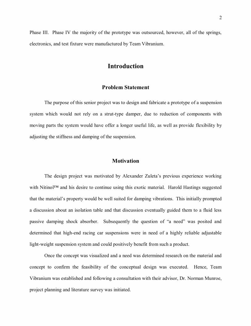
A prototype of passive-damping shock absorber intended for the Florida International
University (FIU), Formula Society of Automotive Engineers (SAE). This shock absorber was
motivated by the idea of an adjustable long-life shock absorber with limited to no moving parts
and/or working fluid. Due to the simplicity of the mechanism, with respect to its moving
components, it was anticipated that a highly reliable weight optimized prototype could be
realized for Formula SAE. Additional considerations for use earthquake damping systems were
discussed, but due to time constraints it was not pursued.
Due to the exotic material properties as well as compatibility considerations with existing
hardware this project was divided into the following four phases: Phase I: Material Selection,
Phase II: Design, Phase III: Analysis and Phase IV: Manufacture. In Phase I a rough estimate of
the working load was established and specific material properties of current automotive springs
were analyzed (i.e. Young’s modulus and yield strength of SAE 9254) and based on the resultant
data an alloy of Nitinol™ (binary or ternary alloy has yet to be determined at this time) was
chosen that had similar properties. During Phase II the geometry of a standard MacPherson Strut
was analyzed and an initial concept for a design that would be compatible with existing
automotive was explored. After the problem was well defined and constrained several rough
sketches were conceived. Subsequently an appropriate design of the spring which was to be the
focus of the shock absorber will be decided upon. SolidWorks® will be utilized as the primary
design software package. At Phase III analysis of the Nitinol™ springs was performed as well as
the shock absorber as a system to ensure that proper standards and proof of concept was
achieved. SolidWorks® and AutoDesk Inventor will be the primary software packages used in
2
Phase III. Phase IV the majority of the prototype was outsourced, however, all of the springs,
electronics, and test fixture were manufactured by Team Vibranium.
Introduction
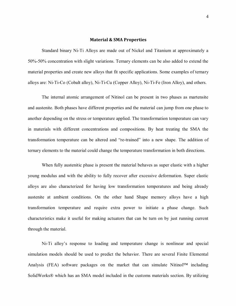
Problem Statement
The purpose of this senior project was to design and fabricate a prototype of a suspension
system which would not rely on a strut-type damper, due to reduction of components with
moving parts the system would have offer a longer useful life, as well as provide flexibility by
adjusting the stiffness and damping of the suspension.
Motivation
The design project was motivated by Alexander Zuleta’s previous experience working
with Nitinol™ and his desire to continue using this exotic material. Harold Hastings suggested
that the material’s property would be well suited for damping vibrations. This initially prompted
a discussion about an isolation table and that discussion eventually guided them to a fluid less
passive damping shock absorber. Subsequently the question of “a need” was posited and
determined that high-end racing car suspensions were in need of a highly reliable adjustable
light-weight suspension system and could positively benefit from such a product.
Once the concept was visualized and a need was determined research on the material and
concept to confirm the feasibility of the conceptual design was executed. Hence, Team
Vibranium was established and following a consultation with their advisor, Dr. Norman Munroe,
project planning and literature survey was initiated.

3
Literature Survey
History & Background Information
Nitinol™ is a popular metal alloy that belongs to the small group of the SMA class. Its
crystalline configuration allows it behave in two ways: superplastic and “smart” in the sense that
it can return to shape after being excessively deformed without experiencing plasticity. Its
properties reside in the material response to heat or mechanical deformation which causes a
variation in its Young’s modulus and phase transformation.
It was discovered in the 1960’s as part of a Naval Ordinance Lab project, and gained
popularity for its high biocompatibility and the high recovery forces that can be generated when
the material is properly constrained during phase transformation. Such interesting behavior
drives research and enthusiasts to innovate into new applications every day.
Applications
Nitinol™ has been extensively used in medical applications due to its high
biocompatibility, flexibility, and desirable surface finish which protected the material from
environmental factors and made it practical for use in the human body; Stents are the typical type
of medical devices that make use of the SMA’s super elastic properties to expand clogged
arteries or serve to support the vein walls.
Yet another application that has become popular is the fabrication of Ni-Ti Actuators that
make use of the shape memory property by producing work when passing electric current
through it which produces heat initiating the phase change which allows it to act as a switch or
tendon.
4
Material & SMA Properties
Standard binary Ni-Ti Alloys are made out of Nickel and Titanium at approximately a
50%-50% concentration with slight variations. Ternary elements can be also added to extend the
material properties and create new alloys that fit specific applications. Some examples of ternary
alloys are: Ni-Ti-Co (Cobalt alloy), Ni-Ti-Cu (Copper Alloy), Ni-Ti-Fe (Iron Alloy), and others.
The internal atomic arrangement of Nitinol can be present in two phases as martensite
and austenite. Both phases have different properties and the material can jump from one phase to
another depending on the stress or temperature applied. The transformation temperature can vary
in materials with different concentrations and compositions. By heat treating the SMA the
transformation temperature can be altered and “re-trained” into a new shape. The addition of
ternary elements to the material could change the temperature transformation in both directions.
When fully austenitic phase is present the material behaves as super elastic with a higher
young modulus and with the ability to fully recover after excessive deformation. Super elastic
alloys are also characterized for having low transformation temperatures and being already
austenite at ambient conditions. On the other hand Shape memory alloys have a high
transformation temperature and require extra power to initiate a phase change. Such
characteristics make it useful for making actuators that can be turn on by just running current
through the material.
Ni-Ti alloy’s response to loading and temperature change is nonlinear and special
simulation models should be used to predict the behavior. There are several Finite Elemental
Analysis (FEA) software packages on the market that can simulate Nitinol™ including
SolidWorks® which has an SMA model included in the customs materials section. By utilizing
5
FEA stress and fatigue analysis, one could aid in the development and optimization of innovative
and reliable products.
The demand of Nitinol has increase globally along with the competition for better quality
and price. The material has also been recognized by the FDA (Food and Drug Administration) as
a safe material. Nitinol is sold in wire, sheet, rod, or billet form with a variety of diameters and
sizes.
Project Formulation
Overview
The design of a Nitinol–based suspension was conceptualized as a way to use the
material’s damping properties and its strong response to heat to have a variable system that could
outperformed in different situations. By constructing martensitic- Nitinol springs and controlling
its phase transformation, the system response can be manipulated since the martensitic phase
shows stronger damping ratios than austenitic.
Project Objectives
To Prototype a variable damping ratio shock absorber with the use of Nitinol as active
material.
To control the characteristics of the suspension by using an electrically controlled heating
source.
To effectively damp high amplitude inputs.
6
Design Specifications & Other Considerations
The design should incorporate both the hysteretic damping and superelastic properties of
Nitinol. Team Vibranium will design a prototype that will be suitable for testing and direct
implementation in the field. At the highest spring coefficient “setting” the prototype should be
able to withstand a 20 lbf load.
The scope of this project was not overwhelming, however, there were very few off-the-
shelf components that were suitable for the structure of the prototype. Additionally, consisting
of only two members, Team Vibranium was not able to effectively distribute areas of expertise
efficiently (i.e. Mechanical Engineer, Electrical Engineer, Systems Engineer, Material Science
Engineer, etc.). Additionally, there were so many unknowns due to the non-linear response of
Nitinol it was difficult to use traditional models for analysis. It should be reaffirmed that this
project was to design a prototype for testing as there are currently no other hysteretic dampers
that also take advantage of the superelastic properties of Nitinol.
Design Alternatives
Overview of Conceptual Designs Developed
As previously described, reference Motivation, the need and feasibility of a fluid less
passive damping shock absorber was determined to be adequate in order to proceed with the
conceptual design. With the intention of narrowing the scope of the project the following
constraints were posited: Ni-Ti Shape Memory Alloy (SMA) that would allow the user to control
the transformation temperature, spring design that will effectively use the tubular housing that
will contain it, utilize existing hardware (shock absorber tubular housing and mounting points)
7
for backwards compatibility and for reference geometry, multiple Ni-Ti alloy compression
springs and mounting plate that will dissipate the energy stored in the coil spring, and a thermal
delivery system that will regulate the temperature of the SMA which will allow the user to
control the phase of the SMA.
Due to the standardized nature of shock absorber housing the subsequent design
alternatives were focused on the design springs because the design problem is well defined and
constrained.
Spring Design 1
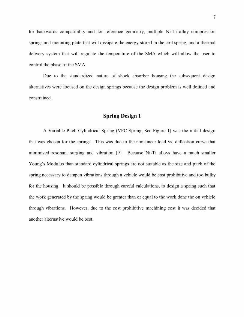
A Variable Pitch Cylindrical Spring (VPC Spring, See Figure 1) was the initial design
that was chosen for the springs. This was due to the non-linear load vs. deflection curve that
minimized resonant surging and vibration [9]. Because Ni-Ti alloys have a much smaller
Young’s Modulus than standard cylindrical springs are not suitable as the size and pitch of the
spring necessary to dampen vibrations through a vehicle would be cost prohibitive and too bulky
for the housing. It should be possible through careful calculations, to design a spring such that
the work generated by the spring would be greater than or equal to the work done the on vehicle
through vibrations. However, due to the cost prohibitive machining cost it was decided that
another alternative would be best.
8
Figure 1 VPC Spring [5]
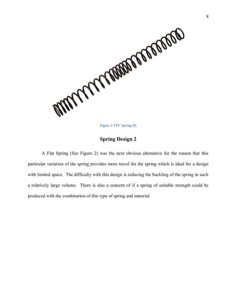
Spring Design 2
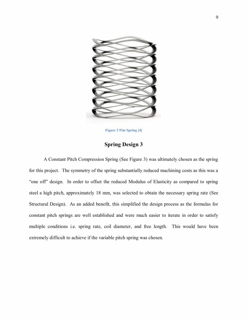
A Flat Spring (See Figure 2) was the next obvious alternative for the reason that this
particular variation of the spring provides more travel for the spring which is ideal for a design
with limited space. The difficulty with this design is reducing the buckling of the spring in such
a relatively large volume. There is also a concern of if a spring of suitable strength could be
produced with the combination of this type of spring and material.
9
Figure 2 Flat Spring [4]
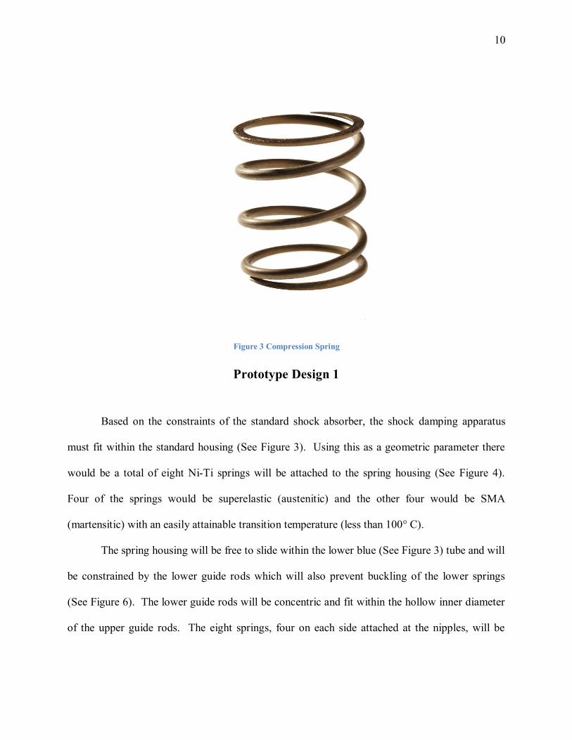
Spring Design 3
A Constant Pitch Compression Spring (See Figure 3) was ultimately chosen as the spring
for this project. The symmetry of the spring substantially reduced machining costs as this was a
“one off” design. In order to offset the reduced Modulus of Elasticity as compared to spring
steel a high pitch, approximately 18 mm, was selected to obtain the necessary spring rate (See
Structural Design). As an added benefit, this simplified the design process as the formulas for
constant pitch springs are well established and were much easier to iterate in order to satisfy
multiple conditions i.e. spring rate, coil diameter, and free length. This would have been
extremely difficult to achieve if the variable pitch spring was chosen.
10
Figure 3 Compression Spring
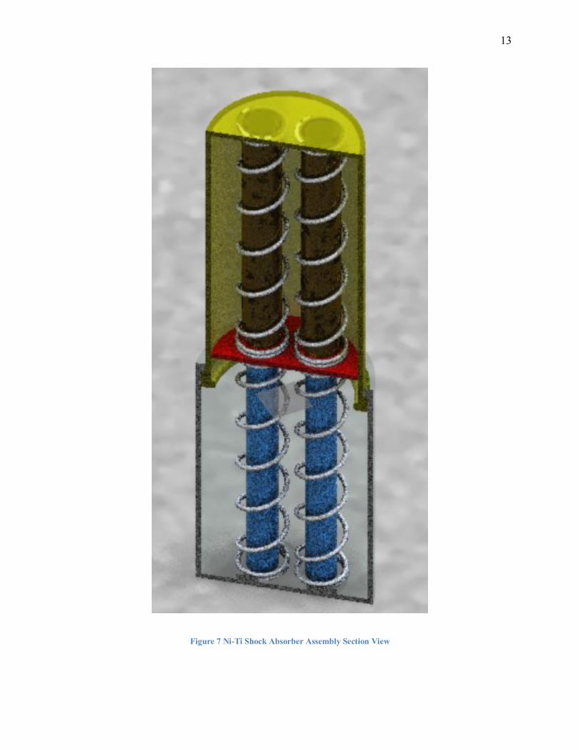
Prototype Design 1
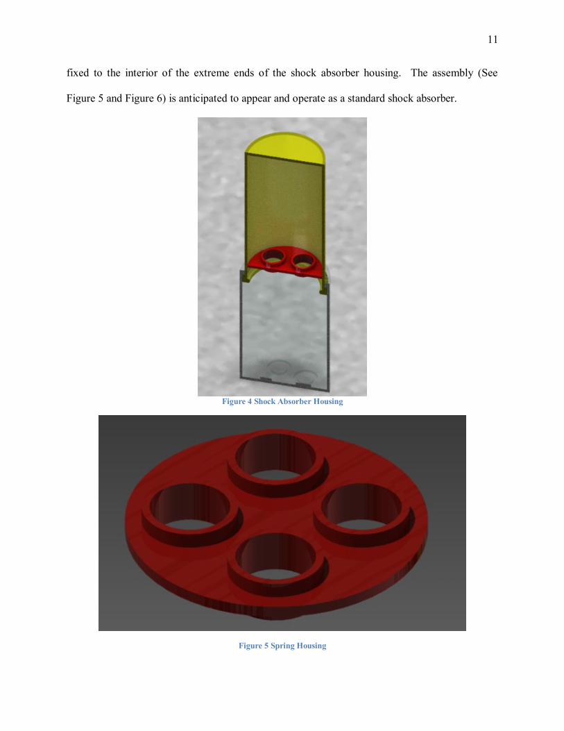
Based on the constraints of the standard shock absorber, the shock damping apparatus
must fit within the standard housing (See Figure 3). Using this as a geometric parameter there
would be a total of eight Ni-Ti springs will be attached to the spring housing (See Figure 4).
Four of the springs would be superelastic (austenitic) and the other four would be SMA
(martensitic) with an easily attainable transition temperature (less than 100° C).
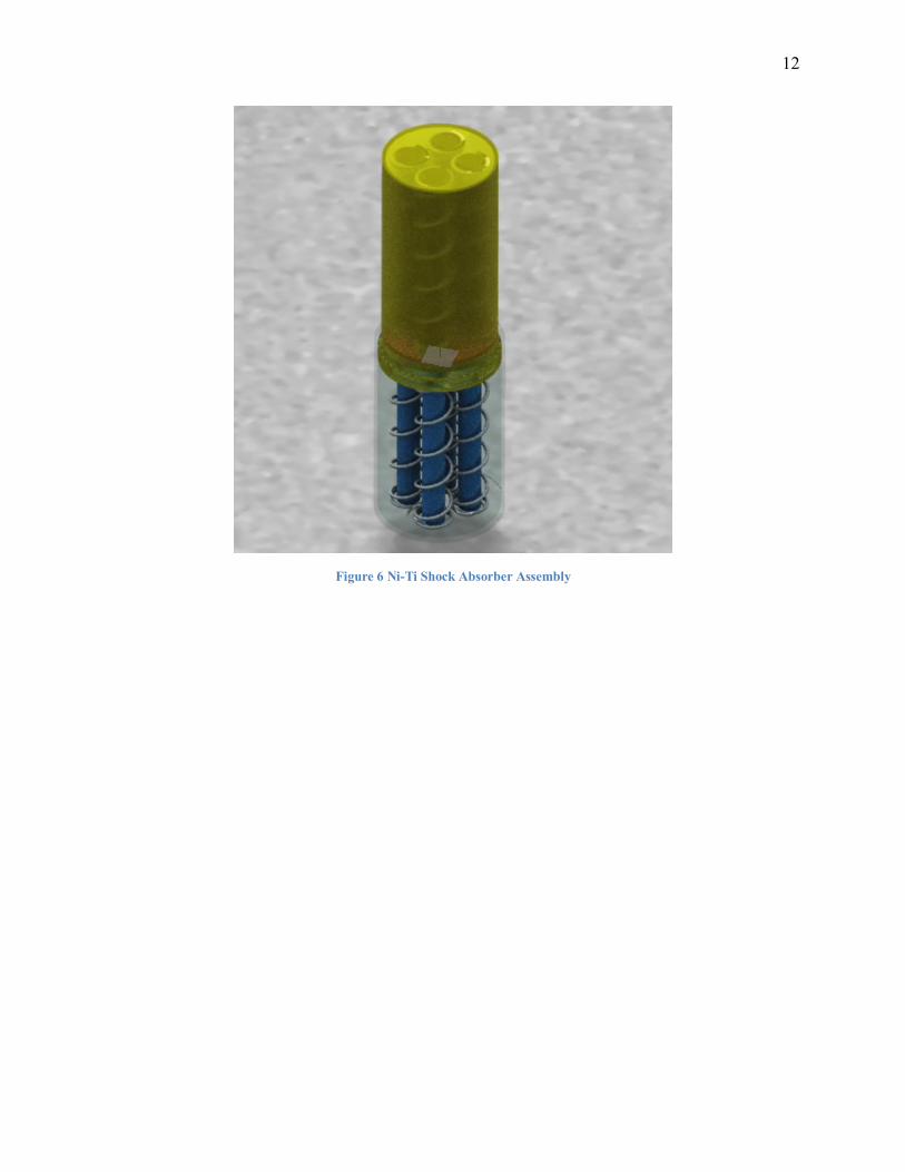
The spring housing will be free to slide within the lower blue (See Figure 3) tube and will
be constrained by the lower guide rods which will also prevent buckling of the lower springs
(See Figure 6). The lower guide rods will be concentric and fit within the hollow inner diameter
of the upper guide rods. The eight springs, four on each side attached at the nipples, will be
11
fixed to the interior of the extreme ends of the shock absorber housing. The assembly (See
Figure 5 and Figure 6) is anticipated to appear and operate as a standard shock absorber.
Figure 4 Shock Absorber Housing
Figure 5 Spring Housing
12
Figure 6 Ni-Ti Shock Absorber Assembly
13
Figure 7 Ni-Ti Shock Absorber Assembly Section View
14
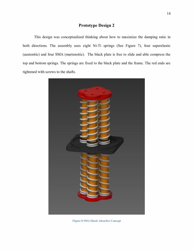
Prototype Design 2
This design was conceptualized thinking about how to maximize the damping ratio in
both directions. The assembly uses eight Ni-Ti springs (See Figure 7), four superelastic
(austenitic) and four SMA (martensitic). The black plate is free to slide and able compress the
top and bottom springs. The springs are fixed to the black plate and the frame. The red ends are
tightened with screws to the shafts.
Figure 8 SMA Shock Absorber Concept
15
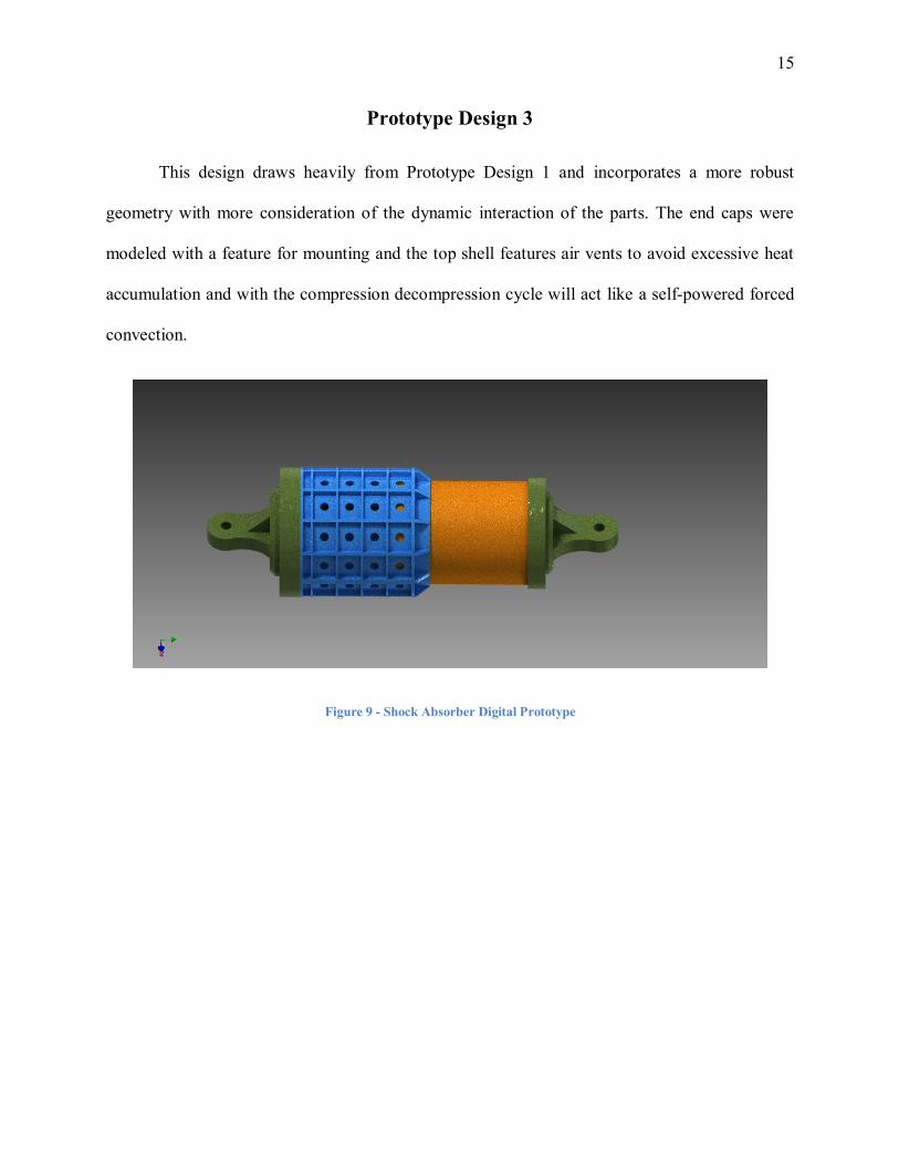
Prototype Design 3
This design draws heavily from Prototype Design 1 and incorporates a more robust
geometry with more consideration of the dynamic interaction of the parts. The end caps were
modeled with a feature for mounting and the top shell features air vents to avoid excessive heat
accumulation and with the compression decompression cycle will act like a self-powered forced
convection.
Figure 9 - Shock Absorber Digital Prototype
16
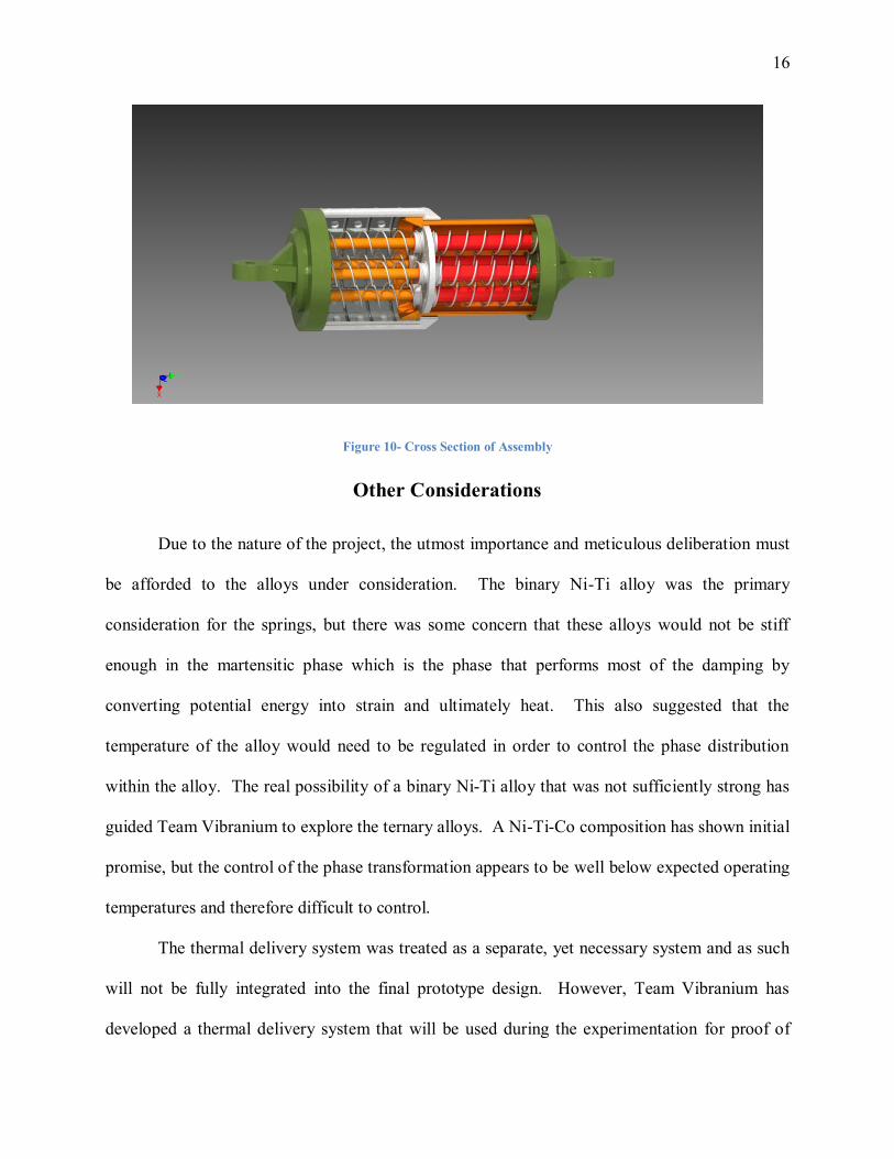
Figure 10- Cross Section of Assembly
Other Considerations
Due to the nature of the project, the utmost importance and meticulous deliberation must
be afforded to the alloys under consideration. The binary Ni-Ti alloy was the primary
consideration for the springs, but there was some concern that these alloys would not be stiff
enough in the martensitic phase which is the phase that performs most of the damping by
converting potential energy into strain and ultimately heat. This also suggested that the
temperature of the alloy would need to be regulated in order to control the phase distribution
within the alloy. The real possibility of a binary Ni-Ti alloy that was not sufficiently strong has
guided Team Vibranium to explore the ternary alloys. A Ni-Ti-Co composition has shown initial
promise, but the control of the phase transformation appears to be well below expected operating
temperatures and therefore difficult to control.
The thermal delivery system was treated as a separate, yet necessary system and as such
will not be fully integrated into the final prototype design. However, Team Vibranium has
developed a thermal delivery system that will be used during the experimentation for proof of
17
concept. This system utilizes an electric current that will passed through the Nitinol springs,
which subsequently will experience an increase in temperature through the mechanism of
resistive heating. This process will be controlled by a micro-controller and Pulse Width
Modulation (PWM) controller in order to regulate the material’s temperature at a desired level.
In order to accurately gauge the amount of power the system consumed a shunt and ammeter was
integrated as the maximum amperage was on the order of 96 amps which was rated almost one
order of magnitude greater than the multi-meters in possession of Team Vibranium.
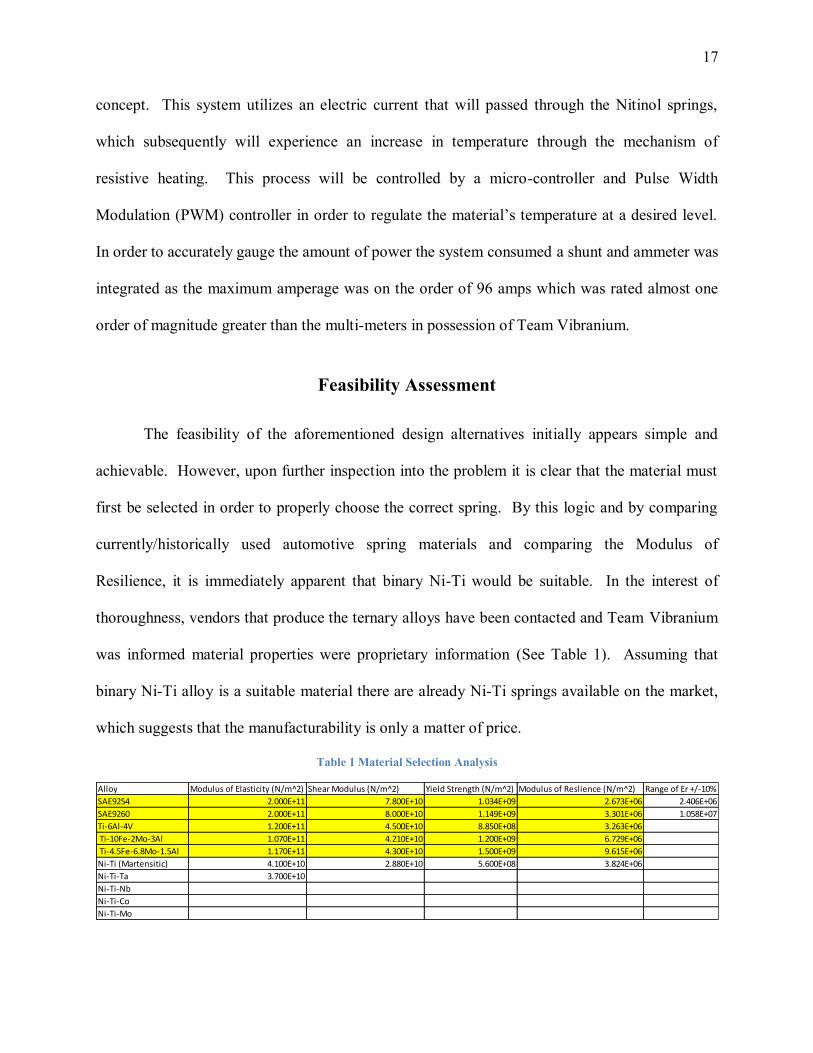
Feasibility Assessment
The feasibility of the aforementioned design alternatives initially appears simple and
achievable. However, upon further inspection into the problem it is clear that the material must
first be selected in order to properly choose the correct spring. By this logic and by comparing
currently/historically used automotive spring materials and comparing the Modulus of
Resilience, it is immediately apparent that binary Ni-Ti would be suitable. In the interest of
thoroughness, vendors that produce the ternary alloys have been contacted and Team Vibranium
was informed material properties were proprietary information (See Table 1). Assuming that
binary Ni-Ti alloy is a suitable material there are already Ni-Ti springs available on the market,
which suggests that the manufacturability is only a matter of price.
Table 1 Material Selection Analysis
Alloy Modulus of Elasticity (N/m^2) Shear Modulus (N/m^2) Yield Strength (N/m^2) Modulus of Reslience (N/m^2) Range of Er +/-10%
SAE9254 2.000E+11 7.800E+10 1.034E+09 2.673E+06 2.406E+06
SAE9260 2.000E+11 8.000E+10 1.149E+09 3.301E+06 1.058E+07
Ti-6Al-4V 1.200E+11 4.500E+10 8.850E+08 3.263E+06
Ti-10Fe-2Mo-3Al 1.070E+11 4.210E+10 1.200E+09 6.729E+06
Ti-4.5Fe-6.8Mo-1.5Al 1.170E+11 4.300E+10 1.500E+09 9.615E+06
Ni-Ti (Martensitic) 4.100E+10 2.880E+10 5.600E+08 3.824E+06
Ni-Ti-Ta 3.700E+10
Ni-Ti-Nb
Ni-Ti-Co
Ni-Ti-Mo
18
Spring Design 3, the constant pitch compression spring, was not the ideal choice for the
performance of the system, but when one factors in cost, manufacturability, and complexity of
design then it was the most suitable selection.
Prototype Design 1 & 2 were concepts that were developed early in the development
process and did not satisfy essential requirements such as: ease of assembly, minimization of
cost, material selection, and machinability. Moreover, a grave oversight was the lack of
consideration of how to mount the damper to a component and/or system. Therefore, Prototype
Design 3 was created by using Prototype Design 1 and implementing all the parameters that were
lacking. Hence, Prototype Design 3 was selected.
Project Management
Overview
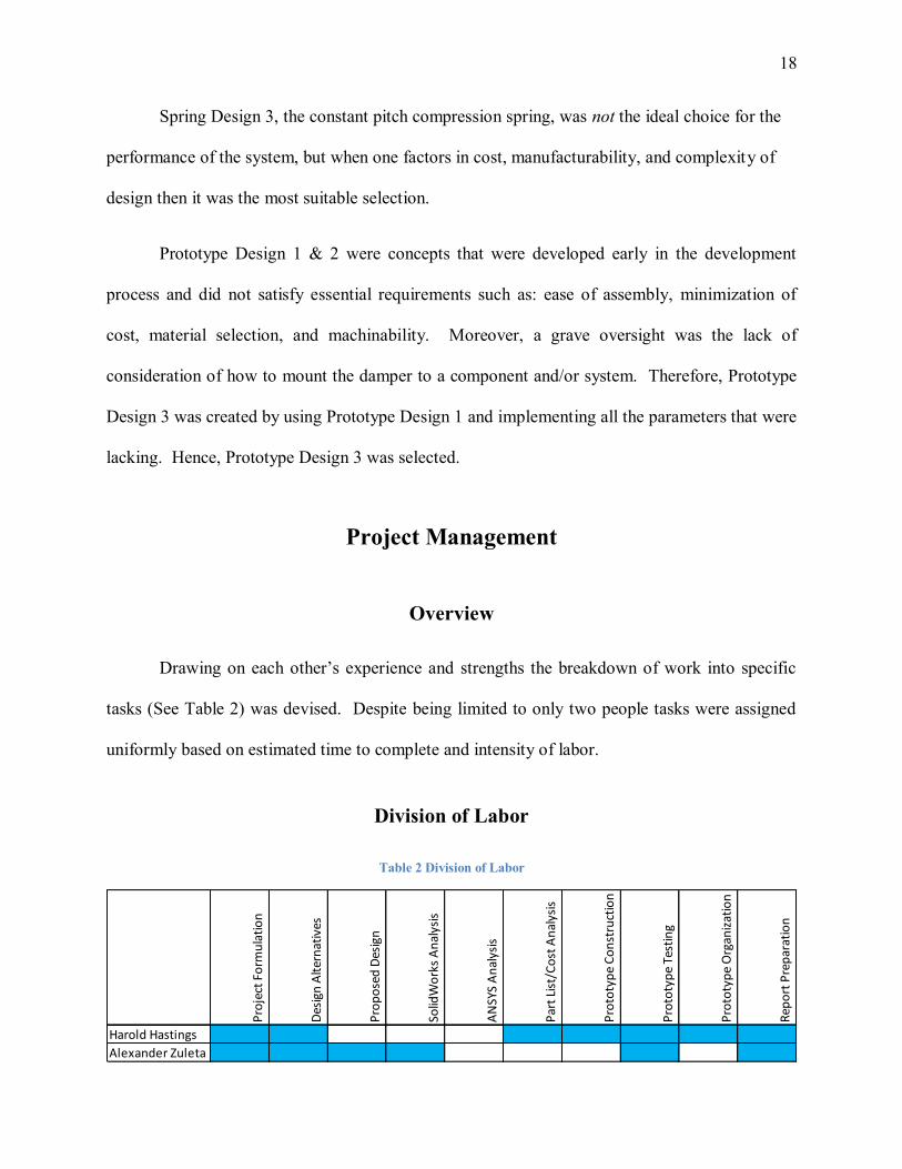
Drawing on each other’s experience and strengths the breakdown of work into specific
tasks (See Table 2) was devised. Despite being limited to only two people tasks were assigned
uniformly based on estimated time to complete and intensity of labor.
Division of Labor
Table 2 Division of Labor
Pro
ject
Fo
rmu
lati
on
Des
ign
Alt
ern
ativ
es
Pro
po
sed
Des
ign
Solid
Wo
rks
An
alys
is
AN
SYS
An
alys
is
Par
t Li
st/C
ost
An
alys
is
Pro
toty
pe
Co
nst
ruct
ion
Pro
toty
pe
Test
ing
Pro
toty
pe
Org
aniz
atio
n
Rep
ort
Pre
par
atio
n
Harold Hastings
Alexander Zuleta
19
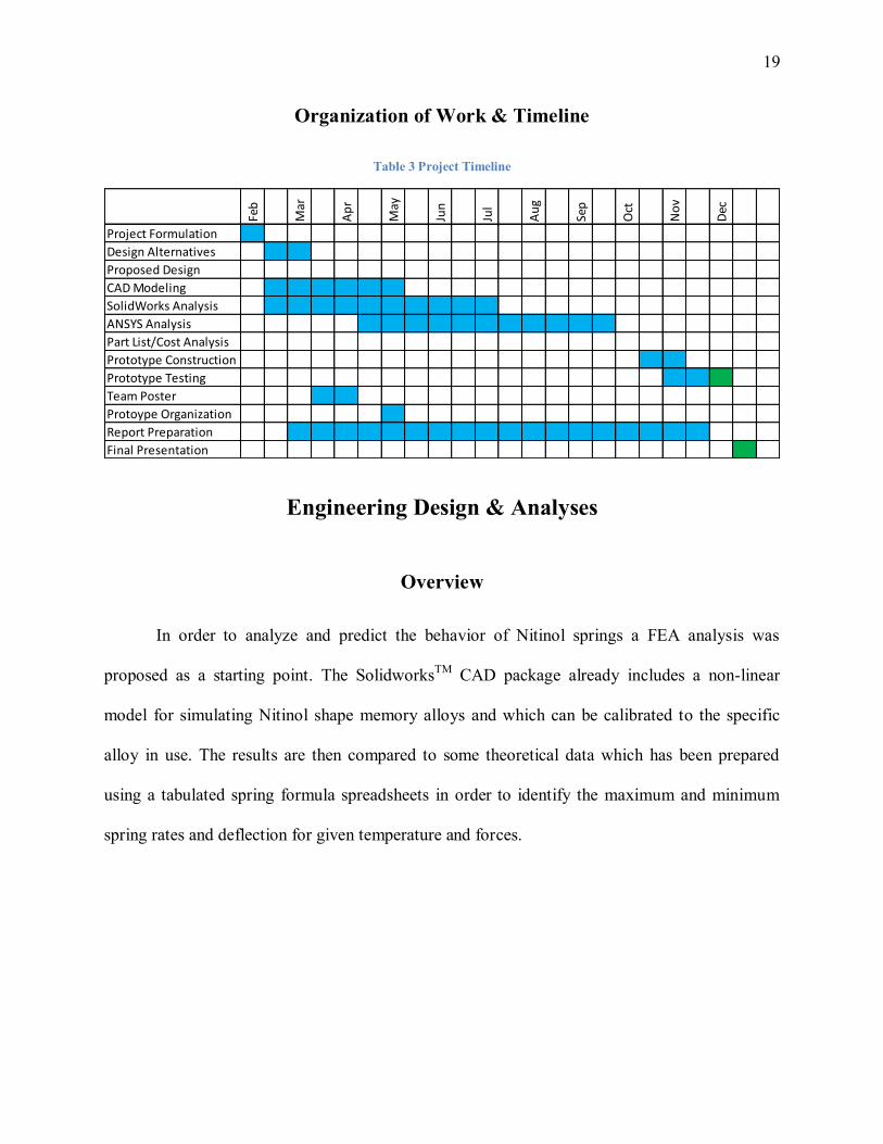
Organization of Work & Timeline
Table 3 Project Timeline
Feb
Mar
Ap
r
May
Jun
Jul
Au
g
Sep
Oct
No
v
Dec
Project Formulation
Design Alternatives
Proposed Design
CAD Modeling
SolidWorks Analysis
ANSYS Analysis
Part List/Cost Analysis
Prototype Construction
Prototype Testing
Team Poster
Protoype Organization
Report Preparation
Final Presentation
Engineering Design & Analyses
Overview
In order to analyze and predict the behavior of Nitinol springs a FEA analysis was
proposed as a starting point. The SolidworksTM
CAD package already includes a non-linear
model for simulating Nitinol shape memory alloys and which can be calibrated to the specific
alloy in use. The results are then compared to some theoretical data which has been prepared
using a tabulated spring formula spreadsheets in order to identify the maximum and minimum
spring rates and deflection for given temperature and forces.
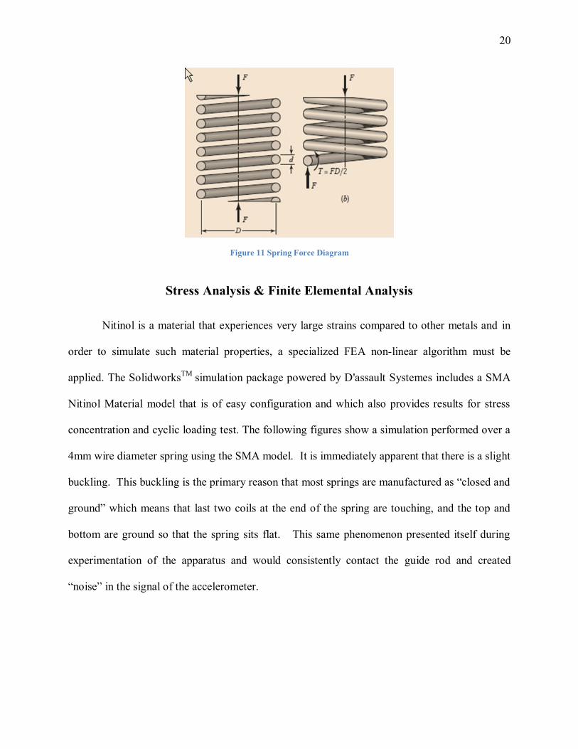
20
Figure 11 Spring Force Diagram
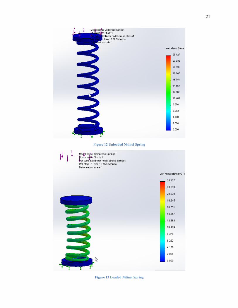
Stress Analysis & Finite Elemental Analysis
Nitinol is a material that experiences very large strains compared to other metals and in
order to simulate such material properties, a specialized FEA non-linear algorithm must be
applied. The SolidworksTM
simulation package powered by D'assault Systemes includes a SMA
Nitinol Material model that is of easy configuration and which also provides results for stress
concentration and cyclic loading test. The following figures show a simulation performed over a
4mm wire diameter spring using the SMA model. It is immediately apparent that there is a slight
buckling. This buckling is the primary reason that most springs are manufactured as “closed and
ground” which means that last two coils at the end of the spring are touching, and the top and
bottom are ground so that the spring sits flat. This same phenomenon presented itself during
experimentation of the apparatus and would consistently contact the guide rod and created
“noise” in the signal of the accelerometer.
21
Figure 12 Unloaded Nitinol Spring
Figure 13 Loaded Nitinol Spring
22
Structural Design
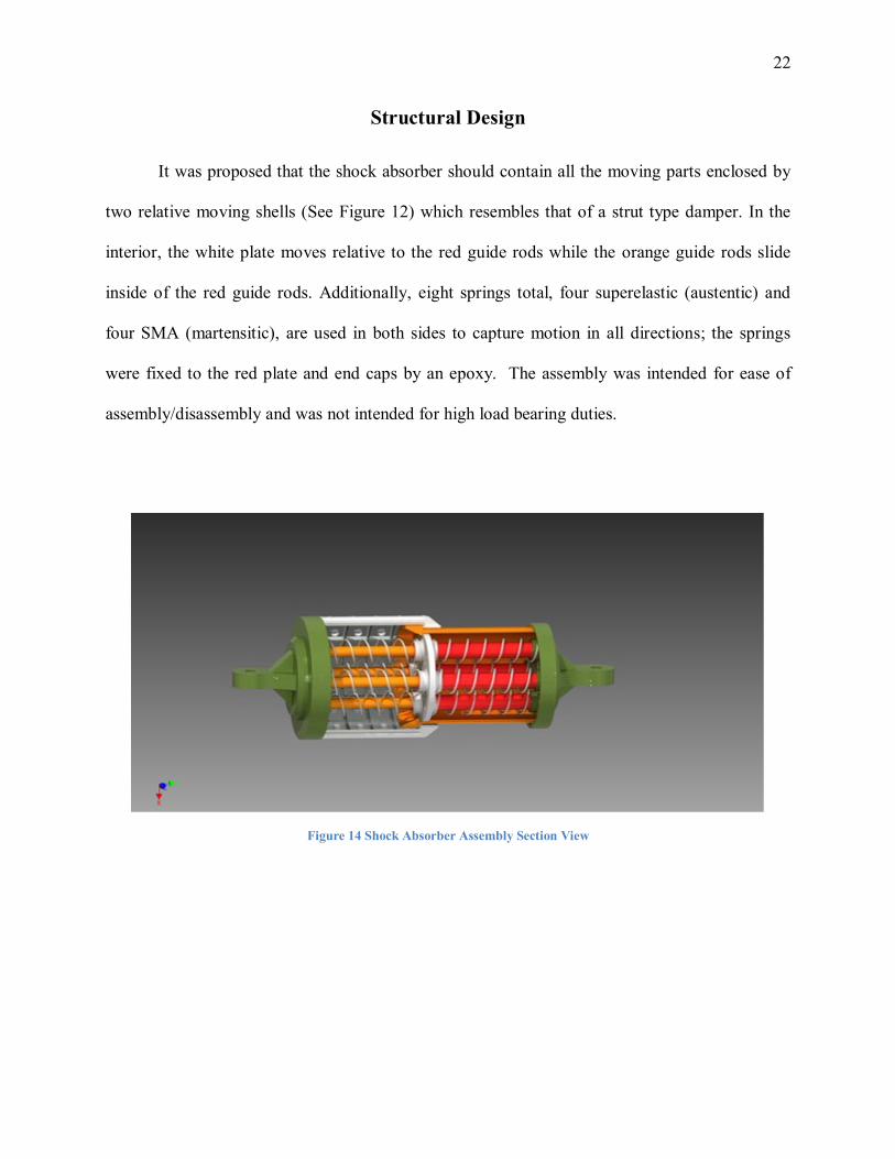
It was proposed that the shock absorber should contain all the moving parts enclosed by
two relative moving shells (See Figure 12) which resembles that of a strut type damper. In the
interior, the white plate moves relative to the red guide rods while the orange guide rods slide
inside of the red guide rods. Additionally, eight springs total, four superelastic (austentic) and
four SMA (martensitic), are used in both sides to capture motion in all directions; the springs
were fixed to the red plate and end caps by an epoxy. The assembly was intended for ease of
assembly/disassembly and was not intended for high load bearing duties.
Figure 14 Shock Absorber Assembly Section View
23
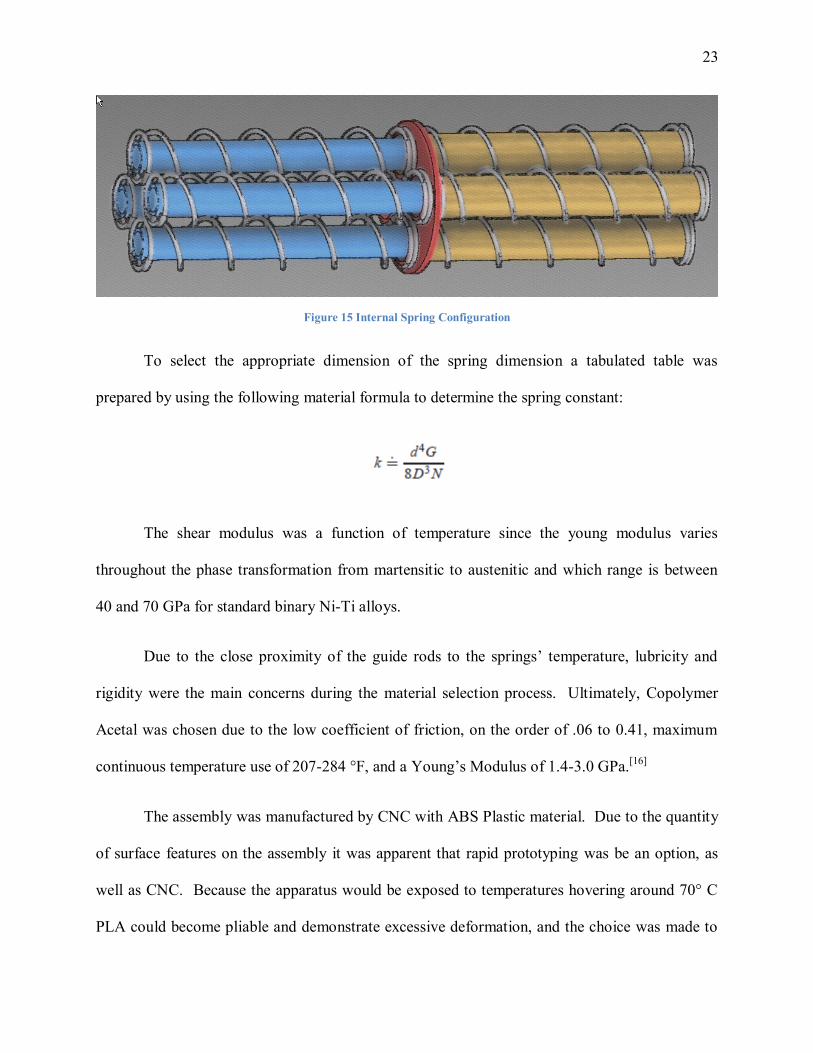
Figure 15 Internal Spring Configuration
To select the appropriate dimension of the spring dimension a tabulated table was
prepared by using the following material formula to determine the spring constant:
The shear modulus was a function of temperature since the young modulus varies
throughout the phase transformation from martensitic to austenitic and which range is between
40 and 70 GPa for standard binary Ni-Ti alloys.
Due to the close proximity of the guide rods to the springs’ temperature, lubricity and
rigidity were the main concerns during the material selection process. Ultimately, Copolymer
Acetal was chosen due to the low coefficient of friction, on the order of .06 to 0.41, maximum
continuous temperature use of 207-284 °F, and a Young’s Modulus of 1.4-3.0 GPa.[16]
The assembly was manufactured by CNC with ABS Plastic material. Due to the quantity
of surface features on the assembly it was apparent that rapid prototyping was be an option, as
well as CNC. Because the apparatus would be exposed to temperatures hovering around 70° C
PLA could become pliable and demonstrate excessive deformation, and the choice was made to
24
use ABS material and outsourcing the manufacturing to China was the quickest and most cost-
effective avenue.
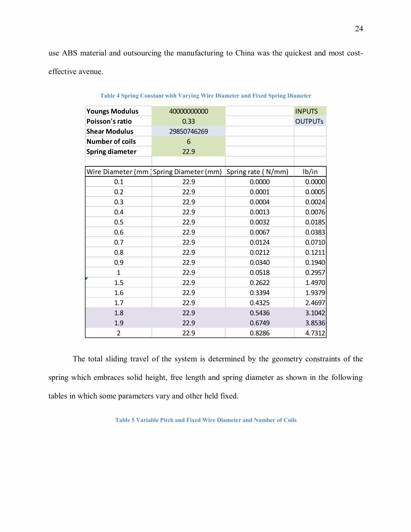
Table 4 Spring Constant with Varying Wire Diameter and Fixed Spring Diameter
Youngs Modulus 40000000000 INPUTS
Poisson's ratio 0.33 OUTPUTs
Shear Modulus 29850746269
Number of coils 6
Spring diameter 22.9
Wire Diameter (mm )Spring Diameter (mm) Spring rate ( N/mm) lb/in
0.1 22.9 0.0000 0.0000
0.2 22.9 0.0001 0.0005
0.3 22.9 0.0004 0.0024
0.4 22.9 0.0013 0.0076
0.5 22.9 0.0032 0.0185
0.6 22.9 0.0067 0.0383
0.7 22.9 0.0124 0.0710
0.8 22.9 0.0212 0.1211
0.9 22.9 0.0340 0.1940
1 22.9 0.0518 0.2957
1.5 22.9 0.2622 1.4970
1.6 22.9 0.3394 1.9379
1.7 22.9 0.4325 2.4697
1.8 22.9 0.5436 3.1042
1.9 22.9 0.6749 3.8536
2 22.9 0.8286 4.7312
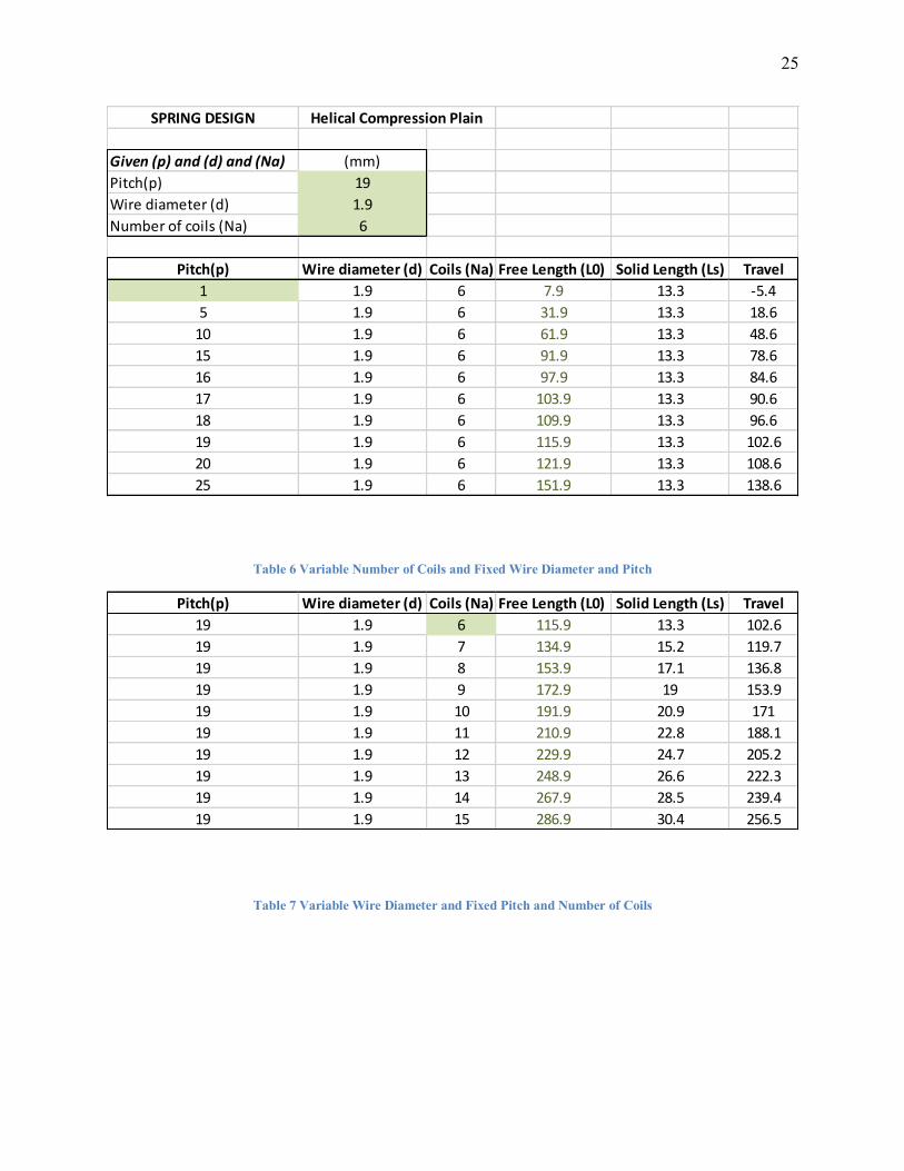
The total sliding travel of the system is determined by the geometry constraints of the
spring which embraces solid height, free length and spring diameter as shown in the following
tables in which some parameters vary and other held fixed.
Table 5 Variable Pitch and Fixed Wire Diameter and Number of Coils
25
SPRING DESIGN
Given (p) and (d) and (Na) (mm)
Pitch(p) 19
Wire diameter (d) 1.9
Number of coils (Na) 6
Pitch(p) Wire diameter (d) Coils (Na) Free Length (L0) Solid Length (Ls) Travel
1 1.9 6 7.9 13.3 -5.4
5 1.9 6 31.9 13.3 18.6
10 1.9 6 61.9 13.3 48.6
15 1.9 6 91.9 13.3 78.6
16 1.9 6 97.9 13.3 84.6
17 1.9 6 103.9 13.3 90.6
18 1.9 6 109.9 13.3 96.6
19 1.9 6 115.9 13.3 102.6
20 1.9 6 121.9 13.3 108.6
25 1.9 6 151.9 13.3 138.6
Helical Compression Plain
Table 6 Variable Number of Coils and Fixed Wire Diameter and Pitch
Pitch(p) Wire diameter (d) Coils (Na) Free Length (L0) Solid Length (Ls) Travel
19 1.9 6 115.9 13.3 102.6
19 1.9 7 134.9 15.2 119.7
19 1.9 8 153.9 17.1 136.8
19 1.9 9 172.9 19 153.9
19 1.9 10 191.9 20.9 171
19 1.9 11 210.9 22.8 188.1
19 1.9 12 229.9 24.7 205.2
19 1.9 13 248.9 26.6 222.3
19 1.9 14 267.9 28.5 239.4
19 1.9 15 286.9 30.4 256.5
Table 7 Variable Wire Diameter and Fixed Pitch and Number of Coils
26
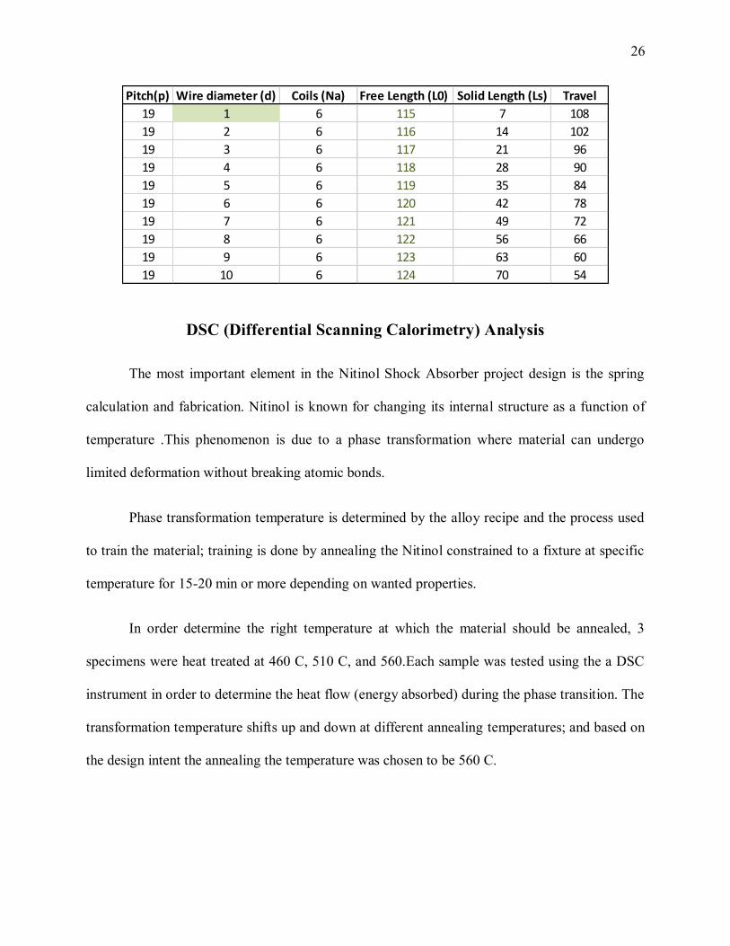
Pitch(p) Wire diameter (d) Coils (Na) Free Length (L0) Solid Length (Ls) Travel
19 1 6 115 7 108
19 2 6 116 14 102
19 3 6 117 21 96
19 4 6 118 28 90
19 5 6 119 35 84
19 6 6 120 42 78
19 7 6 121 49 72
19 8 6 122 56 66
19 9 6 123 63 60
19 10 6 124 70 54
DSC (Differential Scanning Calorimetry) Analysis
The most important element in the Nitinol Shock Absorber project design is the spring
calculation and fabrication. Nitinol is known for changing its internal structure as a function of
temperature .This phenomenon is due to a phase transformation where material can undergo
limited deformation without breaking atomic bonds.
Phase transformation temperature is determined by the alloy recipe and the process used
to train the material; training is done by annealing the Nitinol constrained to a fixture at specific
temperature for 15-20 min or more depending on wanted properties.
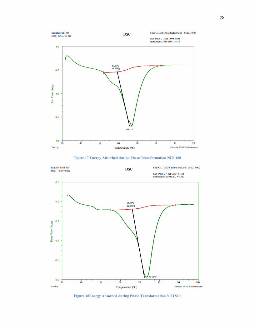
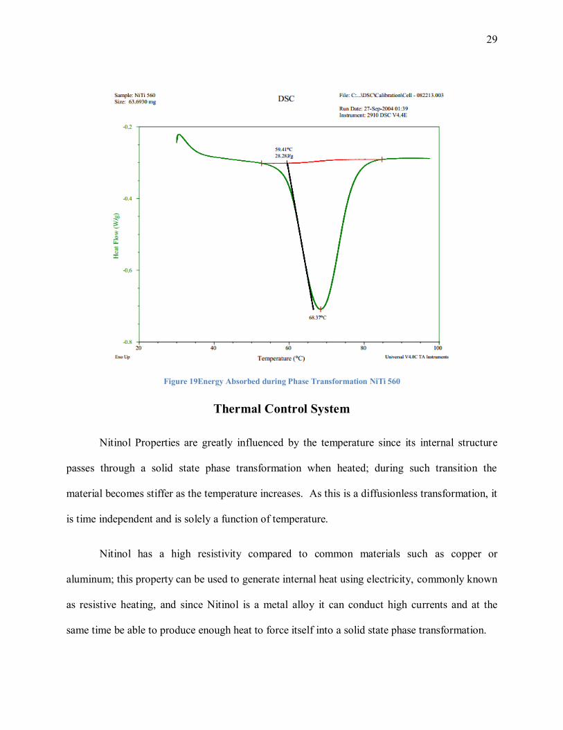
In order determine the right temperature at which the material should be annealed, 3
specimens were heat treated at 460 C, 510 C, and 560.Each sample was tested using the a DSC
instrument in order to determine the heat flow (energy absorbed) during the phase transition. The
transformation temperature shifts up and down at different annealing temperatures; and based on
the design intent the annealing the temperature was chosen to be 560 C.
27
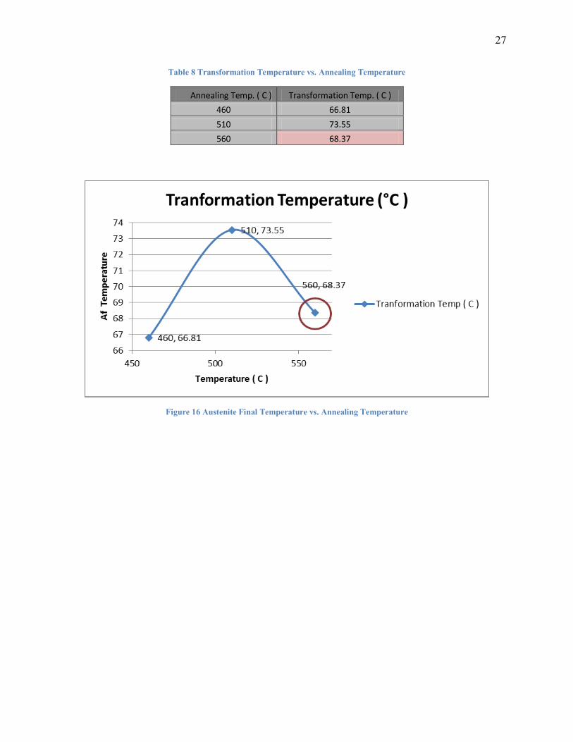
Table 8 Transformation Temperature vs. Annealing Temperature
Annealing Temp. ( C ) Transformation Temp. ( C )
460 66.81
510 73.55
560 68.37
Figure 16 Austenite Final Temperature vs. Annealing Temperature
28
Figure 17 Energy Absorbed during Phase Transformation NiTi 460
Figure 18Energy Absorbed during Phase Transformation NiTi 510
29
Figure 19Energy Absorbed during Phase Transformation NiTi 560
Thermal Control System
Nitinol Properties are greatly influenced by the temperature since its internal structure
passes through a solid state phase transformation when heated; during such transition the
material becomes stiffer as the temperature increases. As this is a diffusionless transformation, it
is time independent and is solely a function of temperature.
Nitinol has a high resistivity compared to common materials such as copper or
aluminum; this property can be used to generate internal heat using electricity, commonly known
as resistive heating, and since Nitinol is a metal alloy it can conduct high currents and at the
same time be able to produce enough heat to force itself into a solid state phase transformation.
30
For the design of a thermally controlled shock absorber, it was ideal to utilize a
microcontroller powered control system to provide such power generation in a quantitative
manner in order to study its behavior under different configurations. A power control using
PWM (Pulse Width Modulation) was chosen as the method by using an Arduino microcontroller
and a MOSFET power controller shell that is capable of switching large currents over high
frequencies.
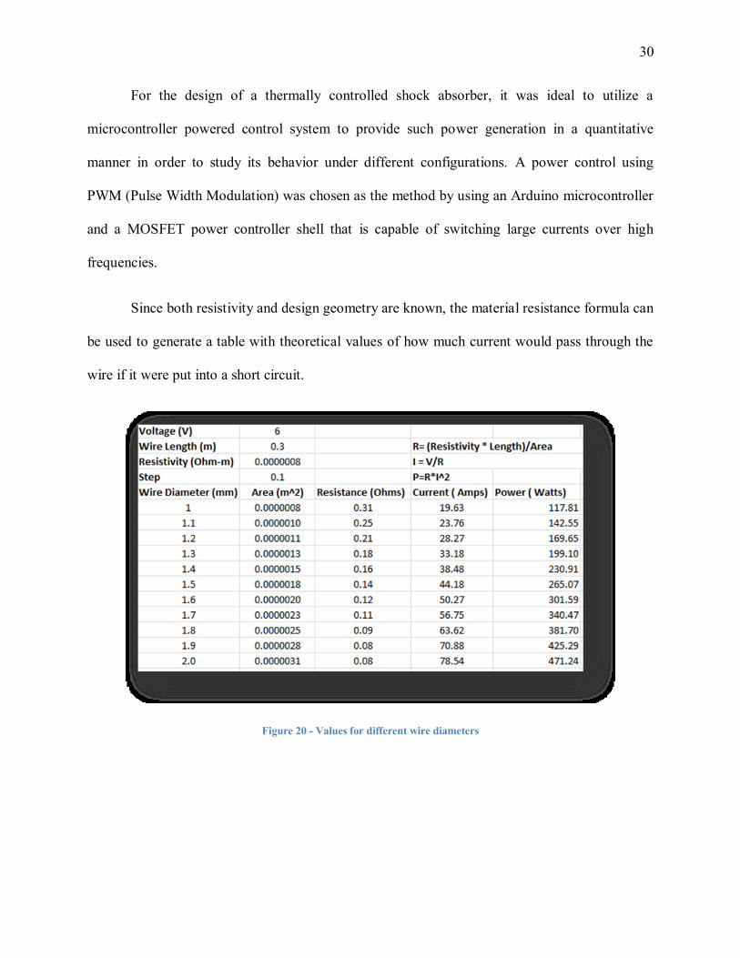
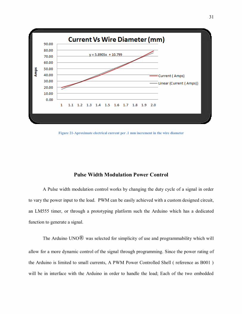
Since both resistivity and design geometry are known, the material resistance formula can
be used to generate a table with theoretical values of how much current would pass through the
wire if it were put into a short circuit.
Figure 20 - Values for different wire diameters
31
Figure 21-Aproximate electrical current per .1 mm increment in the wire diameter
Pulse Width Modulation Power Control
A Pulse width modulation control works by changing the duty cycle of a signal in order
to vary the power input to the load. PWM can be easily achieved with a custom designed circuit,
an LM555 timer, or through a prototyping platform such the Arduino which has a dedicated
function to generate a signal.
The Arduino UNO® was selected for simplicity of use and programmability which will
allow for a more dynamic control of the signal through programming. Since the power rating of
the Arduino is limited to small currents, A PWM Power Controlled Shell ( reference as B001 )
will be in interface with the Arduino in order to handle the load; Each of the two embedded

32
MOSFET embedded are rated to 52 Amperes in a continuously load or pulsed currents up to 310
Amperes.
Figure 22 - Duty Cycle
Figure 23 - PWM Power Controller Shell - B001
Thermal Analysis
The Nitinol based shock absorber will experience high stress due to the carried weight,
the temperature generated by the spring and the input signal strength. In order to perform a
33
material selection FEA and dynamic simulation had to be performed in order to detect weak
points and friction within the parts.
Transient thermal analysis
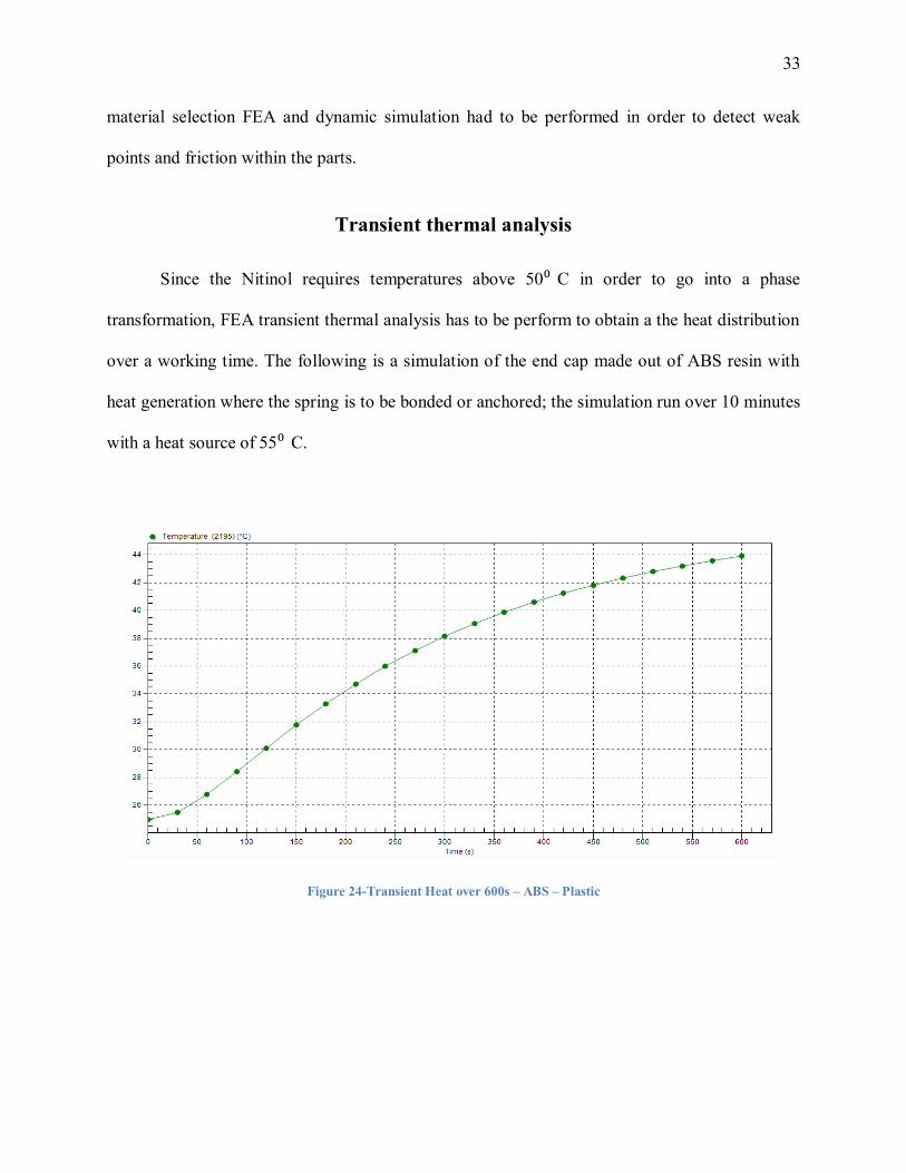
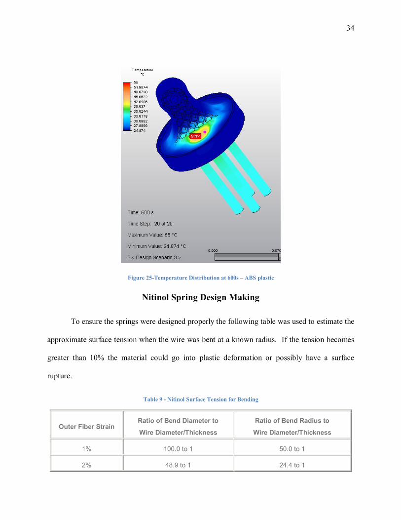
Since the Nitinol requires temperatures above 50⁰ C in order to go into a phase
transformation, FEA transient thermal analysis has to be perform to obtain a the heat distribution
over a working time. The following is a simulation of the end cap made out of ABS resin with
heat generation where the spring is to be bonded or anchored; the simulation run over 10 minutes
with a heat source of 55⁰ C.
Figure 24-Transient Heat over 600s – ABS – Plastic
34
Figure 25-Temperature Distribution at 600s – ABS plastic
Nitinol Spring Design Making
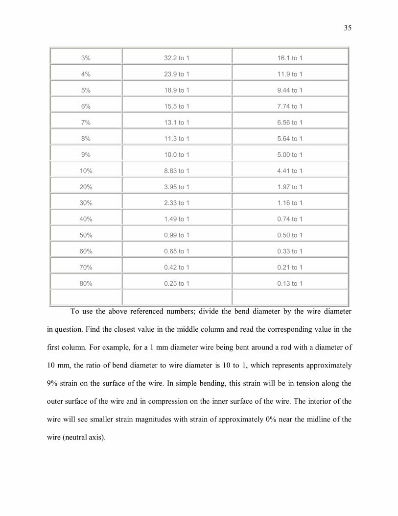
To ensure the springs were designed properly the following table was used to estimate the
approximate surface tension when the wire was bent at a known radius. If the tension becomes
greater than 10% the material could go into plastic deformation or possibly have a surface
rupture.
Table 9 - Nitinol Surface Tension for Bending
Outer Fiber Strain Ratio of Bend Diameter to
Wire Diameter/Thickness
Ratio of Bend Radius to
Wire Diameter/Thickness
1% 100.0 to 1 50.0 to 1
2% 48.9 to 1 24.4 to 1
35
3% 32.2 to 1 16.1 to 1
4% 23.9 to 1 11.9 to 1
5% 18.9 to 1 9.44 to 1
6% 15.5 to 1 7.74 to 1
7% 13.1 to 1 6.56 to 1
8% 11.3 to 1 5.64 to 1
9% 10.0 to 1 5.00 to 1
10% 8.83 to 1 4.41 to 1
20% 3.95 to 1 1.97 to 1
30% 2.33 to 1 1.16 to 1
40% 1.49 to 1 0.74 to 1
50% 0.99 to 1 0.50 to 1
60% 0.65 to 1 0.33 to 1
70% 0.42 to 1 0.21 to 1
80% 0.25 to 1 0.13 to 1
To use the above referenced numbers; divide the bend diameter by the wire diameter
in question. Find the closest value in the middle column and read the corresponding value in the
first column. For example, for a 1 mm diameter wire being bent around a rod with a diameter of
10 mm, the ratio of bend diameter to wire diameter is 10 to 1, which represents approximately
9% strain on the surface of the wire. In simple bending, this strain will be in tension along the
outer surface of the wire and in compression on the inner surface of the wire. The interior of the
wire will see smaller strain magnitudes with strain of approximately 0% near the midline of the
wire (neutral axis).
36
The maximum recoverable strain limits for both Superelastic and shape memory NiTi is
about 6 to 8%. However, 3 to 4% is the recommended limit for product design. The ductility of
NiTi wire which has been cold worked and heat treated is typically 10 to 20% in tension. Fully
annealed NiTi wire has a ductility limit of about 60 to 70%.
Note: The numbers in the above table are approximate values based on general beam theory
calculations for all materials. They have not been specifically calculated for NiTi alloys.[17]
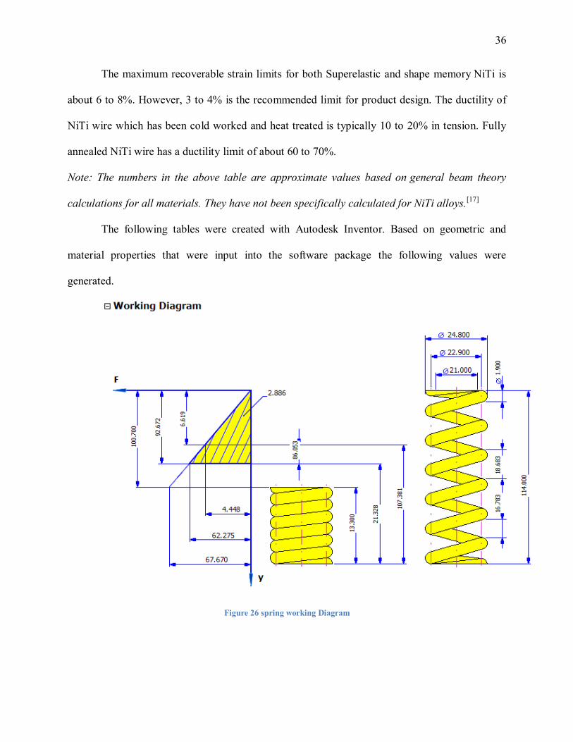
The following tables were created with Autodesk Inventor. Based on geometric and
material properties that were input into the software package the following values were
generated.
Figure 26 spring working Diagram
37
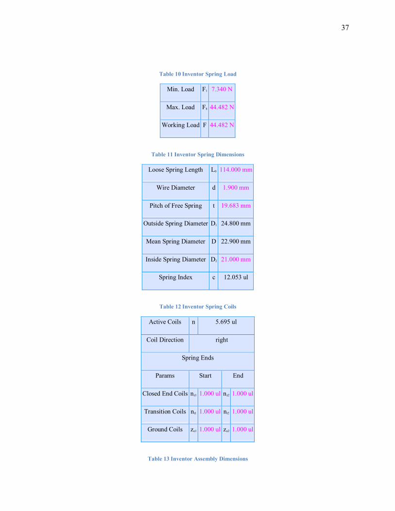
Table 10 Inventor Spring Load
Min. Load F1 7.340 N
Max. Load F8 44.482 N
Working Load F 44.482 N
Table 11 Inventor Spring Dimensions
Loose Spring Length L0 114.000 mm
Wire Diameter d 1.900 mm
Pitch of Free Spring t 19.683 mm
Outside Spring Diameter D1 24.800 mm
Mean Spring Diameter D 22.900 mm
Inside Spring Diameter D2 21.000 mm
Spring Index c 12.053 ul
Table 12 Inventor Spring Coils
Active Coils n 5.695 ul
Coil Direction right
Spring Ends
Params Start End
Closed End Coils nz1 1.000 ul nz2 1.000 ul
Transition Coils nt1 1.000 ul nt2 1.000 ul
Ground Coils zo1 1.000 ul zo2 1.000 ul
Table 13 Inventor Assembly Dimensions
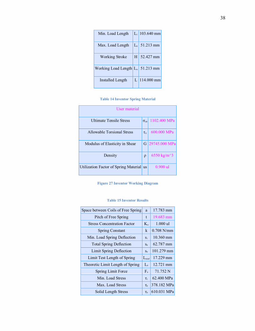
38
Min. Load Length L1 103.640 mm
Max. Load Length L8 51.213 mm
Working Stroke H 52.427 mm
Working Load Length Lw 51.213 mm
Installed Length L 114.000 mm
Table 14 Inventor Spring Material
User material
Ultimate Tensile Stress σult 1102.400 MPa
Allowable Torsional Stress τA 600.000 MPa
Modulus of Elasticity in Shear G 29745.000 MPa
Density ρ 6550 kg/m^3
Utilization Factor of Spring Material us 0.900 ul
Figure 27 Inventor Working Diagram
Table 15 Inventor Results
Space between Coils of Free Spring a 17.783 mm
Pitch of Free Spring t 19.683 mm
Stress Concentration Factor Kw 1.000 ul
Spring Constant k 0.708 N/mm
Min. Load Spring Deflection s1 10.360 mm
Total Spring Deflection s8 62.787 mm
Limit Spring Deflection s9 101.279 mm
Limit Test Length of Spring Lminf 17.229 mm
Theoretic Limit Length of Spring L9 12.721 mm
Spring Limit Force F9 71.752 N
Min. Load Stress τ1 62.400 MPa
Max. Load Stress τ8 378.182 MPa
Solid Length Stress τ9 610.031 MPa
39
Critical Speed of Spring v 11.745 mps
Natural Frequency of Spring Surge f 152.567 Hz
Deformation Energy W8 1.396 J
Wire Length l 563.909 mm
Spring Mass m 0.010 kg
Spring Check Result Positive
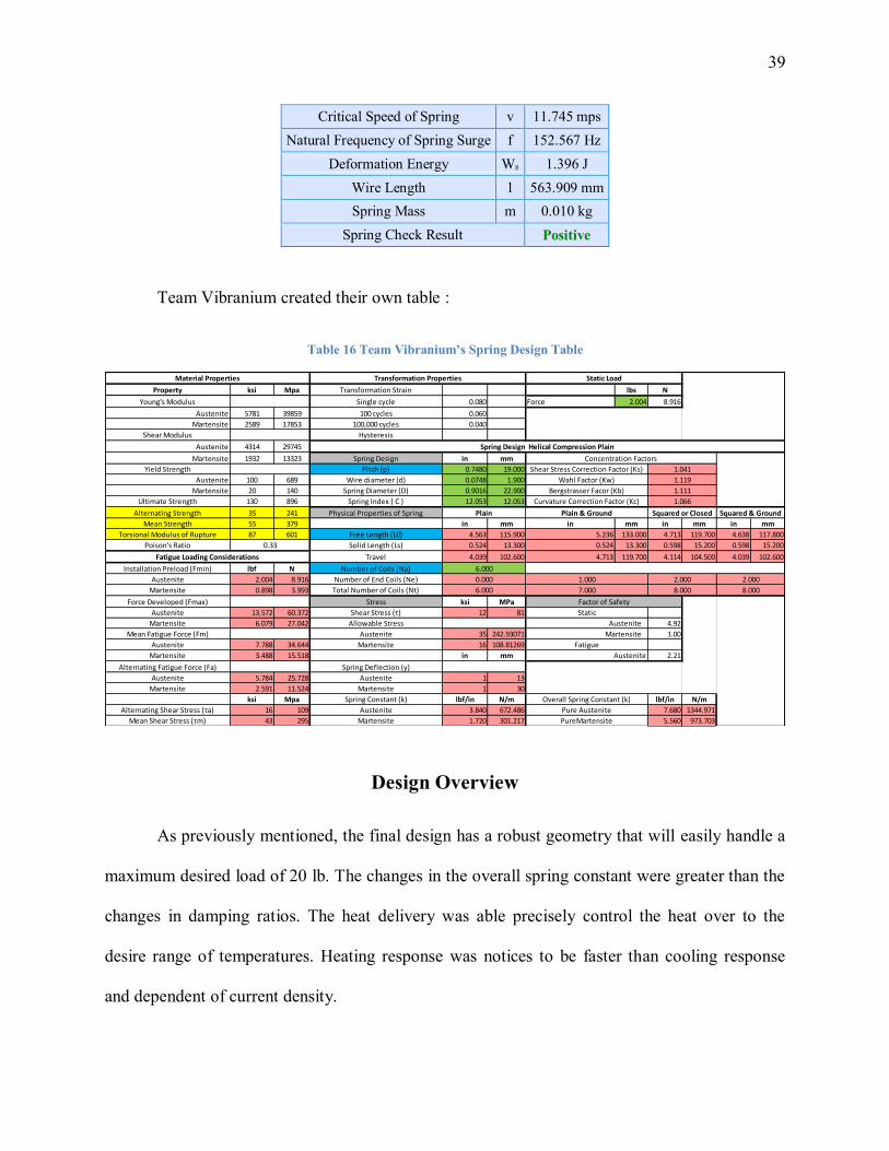
Team Vibranium created their own table :
Table 16 Team Vibranium’s Spring Design Table
ksi Mpa lbs N
0.080 Force 2.004 8.916
5781 39859 0.060
2589 17853 0.040
4314 29745
1932 13323 in mm
0.7480 19.000
100 689 0.0748 1.900
20 140 0.9016 22.900
130 896 12.053 12.053
35 241
55 379 in mm in mm in mm in mm
87 601 4.563 115.900 5.236 133.000 4.713 119.700 4.638 117.800
0.524 13.300 0.524 13.300 0.598 15.200 0.598 15.200
4.039 102.600 4.713 119.700 4.114 104.500 4.039 102.600
lbf N
2.004 8.916
0.898 3.993
ksi MPa
13.572 60.372 12 81
6.079 27.042 4.92
35 242.93071 1.00
7.788 34.644 16 108.81269
3.488 15.518 in mm 2.21
5.784 25.728 1 13
2.591 11.524 1 30
ksi Mpa lbf/in N/m lbf/in N/m
16 109 3.840 672.486 7.680 1344.971
43 295 1.720 301.217 5.560 973.703
Pure Austenite
PureMartensite
Free Length (L0)
Curvature Correction Factor (Kc)
Bergstrasser Facor (Kb)
Wahl Factor (Kw)
Martensite
Martensite
Austenite
Austenite
2.000
8.000
2.000
8.000
0.000
6.000
1.000
7.000
Physical Properties of Spring
Spring Index ( C )
Overall Spring Constant (k)
Torsional Modulus of Rupture
Transformation Strain
Single cycle
100 cycles
100,000 cycles
Shear Modulus
Mean Shear Stress (τm)
Alternating Shear Stress (τa)
Poison's Ratio
Spring Design Helical Compression Plain
Spring Design
Pitch (p)
Wire diameter (d)
Austenite
Martensite
Yield Strength
Austenite
Martensite
Plain Plain & Ground
Martensite
Martensite
Austenite
Alternating Fatigue Force (Fa)
Martensite
Martensite
Installation Preload (Fmin)
Fatigue Loading Considerations
Austenite
Austenite
Mean Fatigue Force (Fm)
Martensite
Austenite
Force Developed (Fmax)
Shear Stress (τ)
Stress
Allowable Stress
Martensite
Austenite
Spring Constant (k)
Spring Deflection (y)
Ultimate Strength
Alternating Strength
Mean Strength
Material Properties
Property
Young's Modulus
Austenite
Martensite
Transformation Properties
Hysteresis
1.119
1.111
1.066
1.041
Squared or Closed Squared & Ground
Concentration Factors
Shear Stress Correction Factor (Ks)
Spring Diameter (D)
Static Load
0.33
Austenite
Austenite
Static
Fatigue
Factor of Safety
Number of End Coils (Ne)
Number of Coils (Na)
Travel
Solid Length (Ls)
Total Number of Coils (Nt)
6.000
Design Overview
As previously mentioned, the final design has a robust geometry that will easily handle a
maximum desired load of 20 lb. The changes in the overall spring constant were greater than the
changes in damping ratios. The heat delivery was able precisely control the heat over to the
desire range of temperatures. Heating response was notices to be faster than cooling response
and dependent of current density.
40
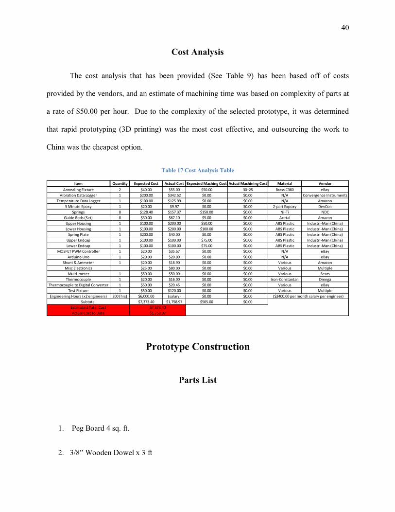
Cost Analysis
The cost analysis that has been provided (See Table 9) has been based off of costs
provided by the vendors, and an estimate of machining time was based on complexity of parts at
a rate of $50.00 per hour. Due to the complexity of the selected prototype, it was determined
that rapid prototyping (3D printing) was the most cost effective, and outsourcing the work to
China was the cheapest option.
Table 17 Cost Analysis Table
Item Quantity Expected Cost Actual Cost Expected Maching Cost Actual Machining Cost Material Vendor
Annealing Fixture 2 $40.00 $55.00 $50.00 30+25 Brass C360 eBay
Vibration Data Logger 1 $200.00 $342.52 $0.00 $0.00 N/A Convergence Instruments
Temperature Data Logger 1 $100.00 $125.99 $0.00 $0.00 N/A Amazon
5 Minute Epoxy 1 $20.00 $9.97 $0.00 $0.00 2-part Expoxy DevCon
Springs 8 $128.40 $157.37 $150.00 $0.00 Ni-Ti NDC
Guide Rods (Set) 8 $30.00 $67.10 $5.00 $0.00 Acetal Amazon
Upper Housing 1 $100.00 $200.00 $50.00 $0.00 ABS Plastic Industri-Man (China)
Lower Housing 1 $100.00 $200.00 $100.00 $0.00 ABS Plastic Industri-Man (China)
Spring Plate 1 $200.00 $40.00 $0.00 $0.00 ABS Plastic Industri-Man (China)
Upper Endcap 1 $100.00 $100.00 $75.00 $0.00 ABS Plastic Industri-Man (China)
Lower Endcap 1 $100.00 $100.00 $75.00 $0.00 ABS Plastic Industri-Man (China)
MOSFET PWM Controller 1 $20.00 $35.67 $0.00 $0.00 N/A eBay
Arduino Uno 1 $20.00 $20.00 $0.00 $0.00 N/A eBay
Shunt & Ammeter 1 $20.00 $18.90 $0.00 $0.00 Various Amazon
Misc Electronics $25.00 $80.00 $0.00 $0.00 Various Multiple
Multi-meter 1 $50.00 $50.00 $0.00 $0.00 Various Sears
Thermocouple 1 $20.00 $16.00 $0.00 $0.00 Iron-Constantan Omega
Thermocouple to Digital Converter 1 $50.00 $20.45 $0.00 $0.00 Various eBay
Test Fixture 1 $50.00 $120.00 $0.00 $0.00 Various Multiple
Engineering Hours (x2 engineers) 200 (hrs) $6,000.00 (salary) $0.00 $0.00
$7,373.40 $1,758.97 $505.00 $0.00
($2400.00 per month salary per engineer)
Subtotal
Estimated Total Cost
Actual Cost to Date
$7,878.40
$1,758.97
Prototype Construction
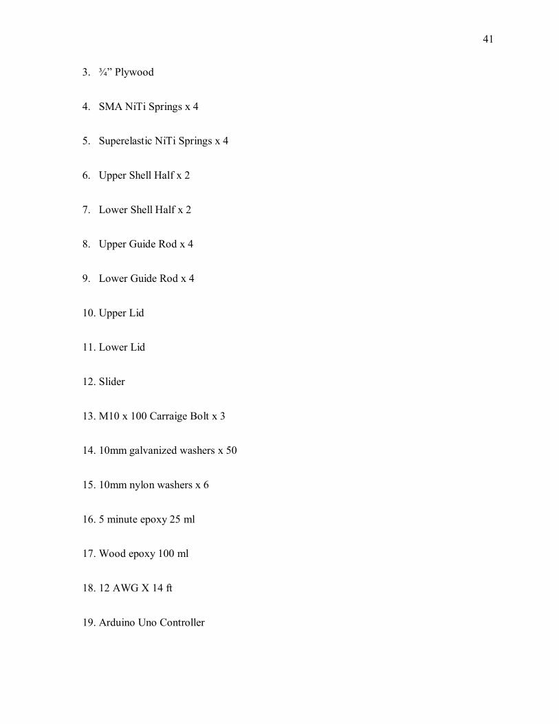
Parts List
1. Peg Board 4 sq. ft.
2. 3/8” Wooden Dowel x 3 ft
41
3. ¾” Plywood
4. SMA NiTi Springs x 4
5. Superelastic NiTi Springs x 4
6. Upper Shell Half x 2
7. Lower Shell Half x 2
8. Upper Guide Rod x 4
9. Lower Guide Rod x 4
10. Upper Lid
11. Lower Lid
12. Slider
13. M10 x 100 Carraige Bolt x 3
14. 10mm galvanized washers x 50
15. 10mm nylon washers x 6
16. 5 minute epoxy 25 ml
17. Wood epoxy 100 ml
18. 12 AWG X 14 ft
19. Arduino Uno Controller
42
20. Type J Thermocouple
21. Digital to Analog Thermocouple converter
22. PWM Power Controller Shell
23. 100 Watt Shunt Ammeter combination
24. Power Resistor 0.25Ω - 1Ω x 2
25. Various Electrical Connectors
Construction
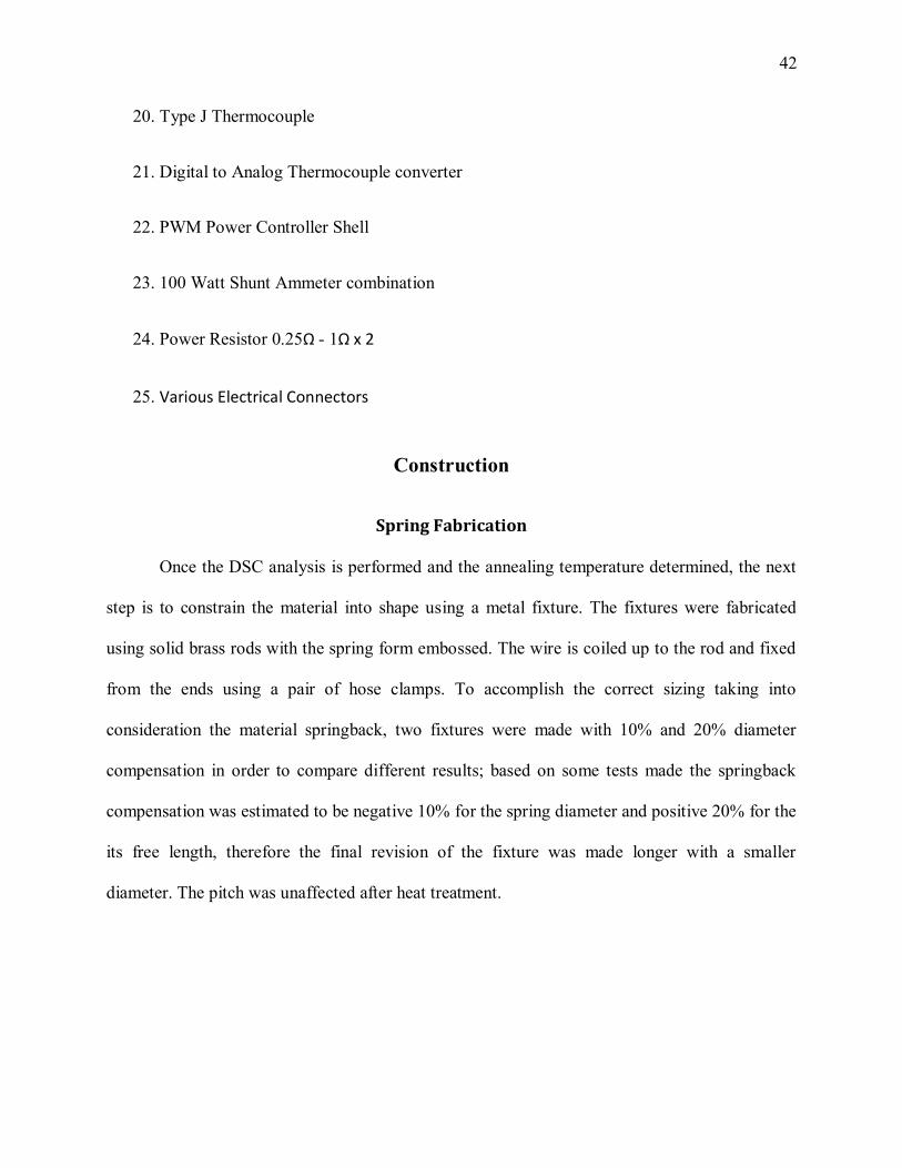
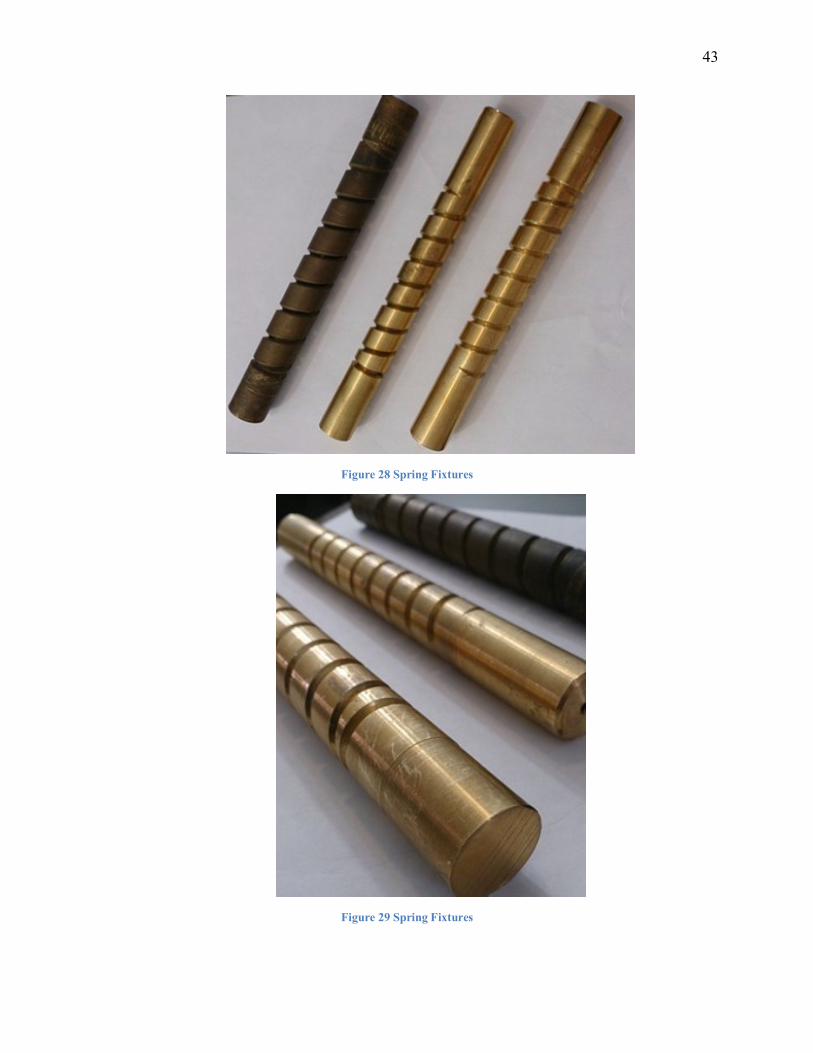
Spring Fabrication
Once the DSC analysis is performed and the annealing temperature determined, the next
step is to constrain the material into shape using a metal fixture. The fixtures were fabricated
using solid brass rods with the spring form embossed. The wire is coiled up to the rod and fixed
from the ends using a pair of hose clamps. To accomplish the correct sizing taking into
consideration the material springback, two fixtures were made with 10% and 20% diameter
compensation in order to compare different results; based on some tests made the springback
compensation was estimated to be negative 10% for the spring diameter and positive 20% for the
its free length, therefore the final revision of the fixture was made longer with a smaller
diameter. The pitch was unaffected after heat treatment.
43
Figure 28 Spring Fixtures
Figure 29 Spring Fixtures
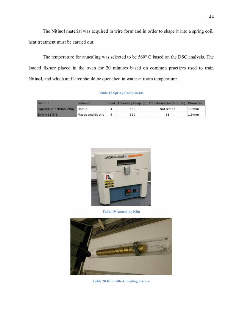
44
The Nitinol material was acquired in wire form and in order to shape it into a spring coil,
heat treatment must be carried out.
The temperature for annealing was selected to be 560° C based on the DSC analysis. The
loaded fixture placed in the oven for 20 minutes based on common practices used to train
Nitinol, and which and later should be quenched in water at room temperature.
Table 18 Spring Components
Material Behavior Count Annealing Temp. (C) Transformation Temp.(C) Diameter
Superelastic Nitinol Alloy Elastic 4 560 Not tested 1.9 mm
SMA Ni51Ti49 Plastic and Elastic 4 560 68 1.9 mm
Table 19 Annealing Kiln
Table 20 Kiln with Annealing Fixture
45
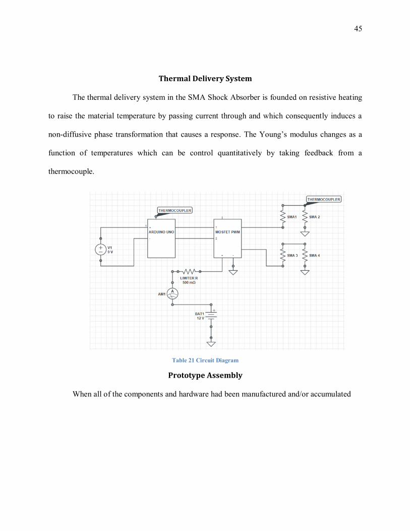
Thermal Delivery System
The thermal delivery system in the SMA Shock Absorber is founded on resistive heating
to raise the material temperature by passing current through and which consequently induces a
non-diffusive phase transformation that causes a response. The Young’s modulus changes as a
function of temperatures which can be control quantitatively by taking feedback from a
thermocouple.
Table 21 Circuit Diagram
Prototype Assembly
When all of the components and hardware had been manufactured and/or accumulated
46
Testing & Evaluation
Overview
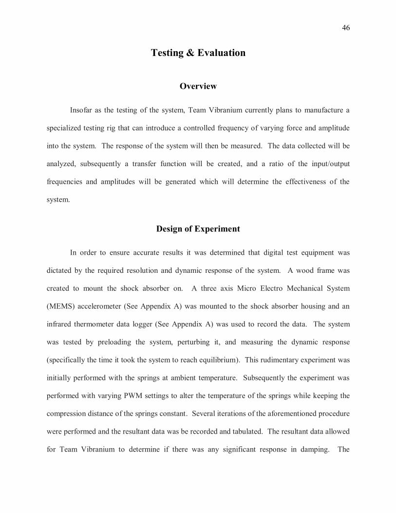
Insofar as the testing of the system, Team Vibranium currently plans to manufacture a
specialized testing rig that can introduce a controlled frequency of varying force and amplitude
into the system. The response of the system will then be measured. The data collected will be
analyzed, subsequently a transfer function will be created, and a ratio of the input/output
frequencies and amplitudes will be generated which will determine the effectiveness of the
system.
Design of Experiment
In order to ensure accurate results it was determined that digital test equipment was
dictated by the required resolution and dynamic response of the system. A wood frame was
created to mount the shock absorber on. A three axis Micro Electro Mechanical System
(MEMS) accelerometer (See Appendix A) was mounted to the shock absorber housing and an
infrared thermometer data logger (See Appendix A) was used to record the data. The system
was tested by preloading the system, perturbing it, and measuring the dynamic response
(specifically the time it took the system to reach equilibrium). This rudimentary experiment was
initially performed with the springs at ambient temperature. Subsequently the experiment was
performed with varying PWM settings to alter the temperature of the springs while keeping the
compression distance of the springs constant. Several iterations of the aforementioned procedure
were performed and the resultant data was be recorded and tabulated. The resultant data allowed
for Team Vibranium to determine if there was any significant response in damping. The
47
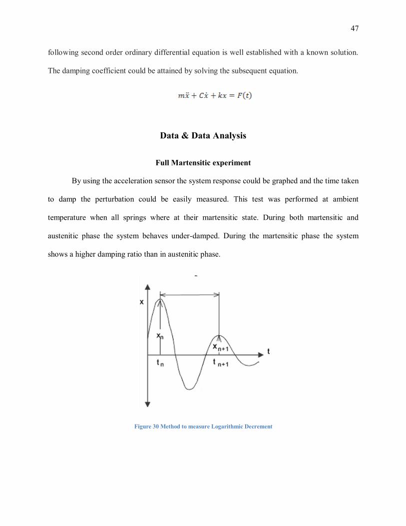
following second order ordinary differential equation is well established with a known solution.
The damping coefficient could be attained by solving the subsequent equation.
Data & Data Analysis
Full Martensitic experiment
By using the acceleration sensor the system response could be graphed and the time taken
to damp the perturbation could be easily measured. This test was performed at ambient
temperature when all springs where at their martensitic state. During both martensitic and
austenitic phase the system behaves under-damped. During the martensitic phase the system
shows a higher damping ratio than in austenitic phase.
Figure 30 Method to measure Logarithmic Decrement
48
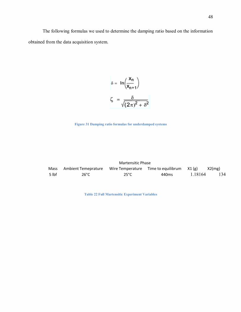
The following formulas we used to determine the damping ratio based on the information
obtained from the data acquisition system.
Figure 31 Damping ratio formulas for underdamped systems
Mass Ambient Temeprature Wire Temperature Time to equilibrum X1 (g) X2(mg)
5 lbf 26°C 25°C 440ms 1.18164 134
Martensitic Phase
Table 22 Full Martensitic Experiment Variables
49
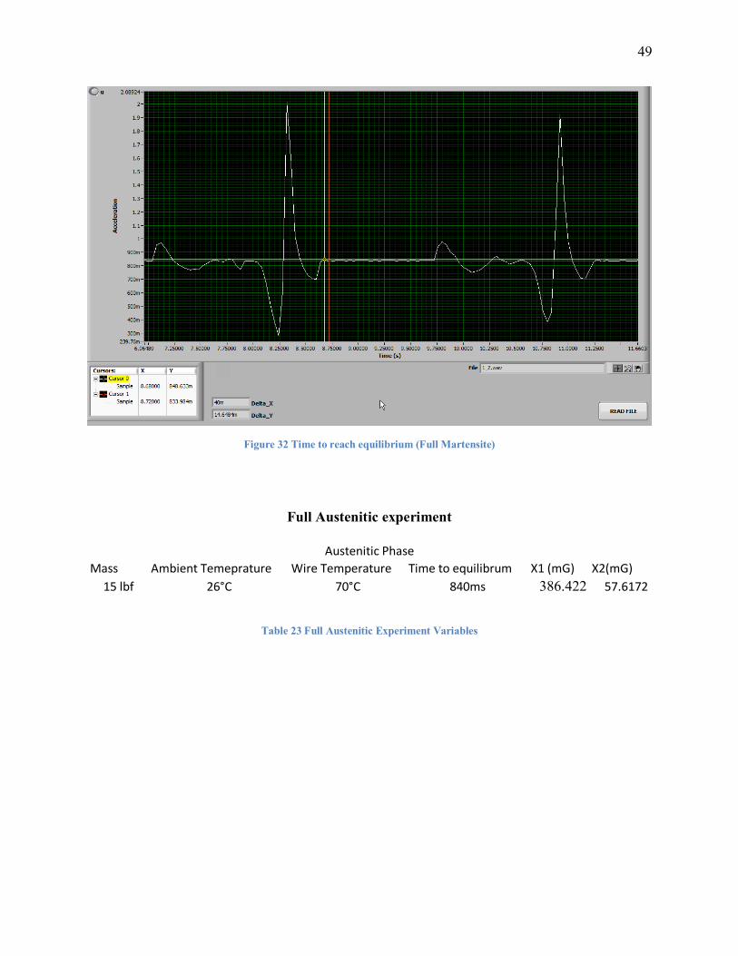
Figure 32 Time to reach equilibrium (Full Martensite)
Full Austenitic experiment
Mass Ambient Temeprature Wire Temperature Time to equilibrum X1 (mG) X2(mG)
15 lbf 26°C 70°C 840ms 386.422 57.6172
Austenitic Phase
Table 23 Full Austenitic Experiment Variables
50
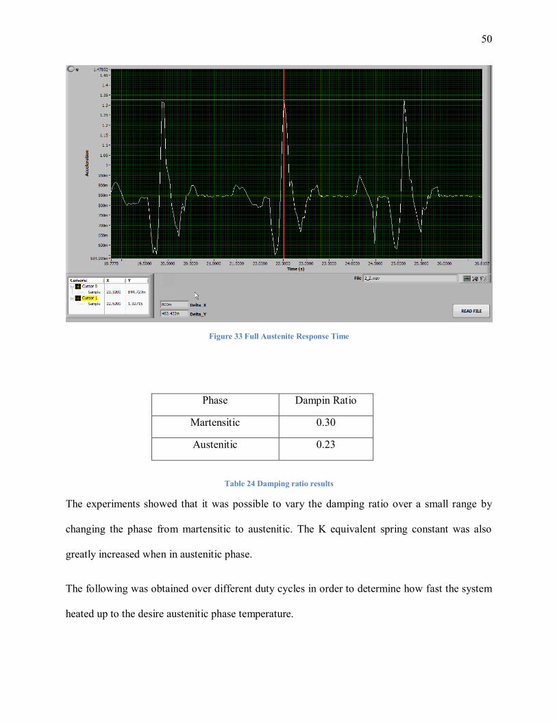
Figure 33 Full Austenite Response Time
Phase Dampin Ratio
Martensitic 0.30
Austenitic 0.23
Table 24 Damping ratio results
The experiments showed that it was possible to vary the damping ratio over a small range by
changing the phase from martensitic to austenitic. The K equivalent spring constant was also
greatly increased when in austenitic phase.
The following was obtained over different duty cycles in order to determine how fast the system
heated up to the desire austenitic phase temperature.
51
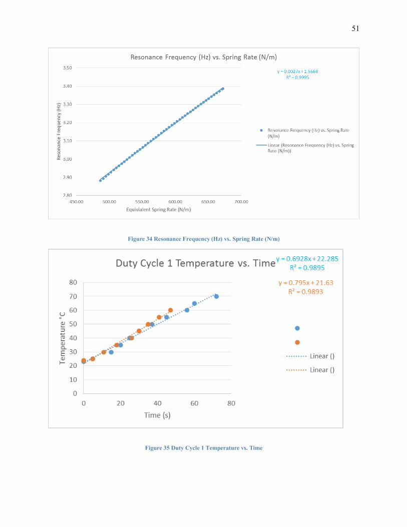
Figure 34 Resonance Frequency (Hz) vs. Spring Rate (N/m)
Figure 35 Duty Cycle 1 Temperature vs. Time
52
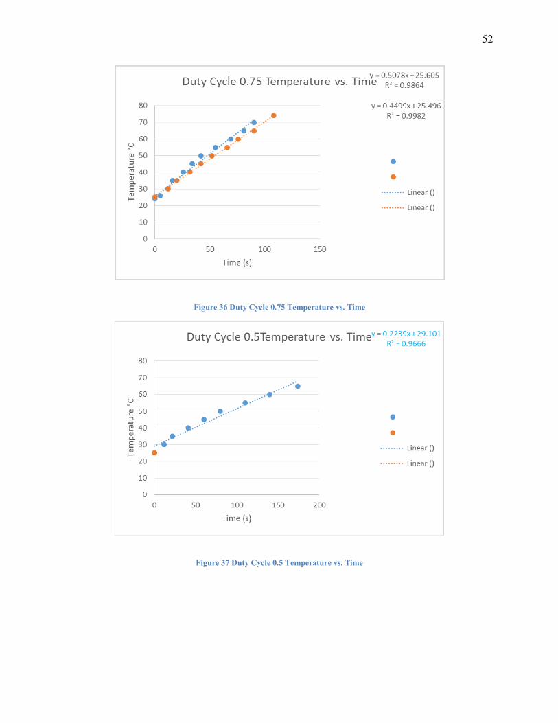
Figure 36 Duty Cycle 0.75 Temperature vs. Time
Figure 37 Duty Cycle 0.5 Temperature vs. Time
53
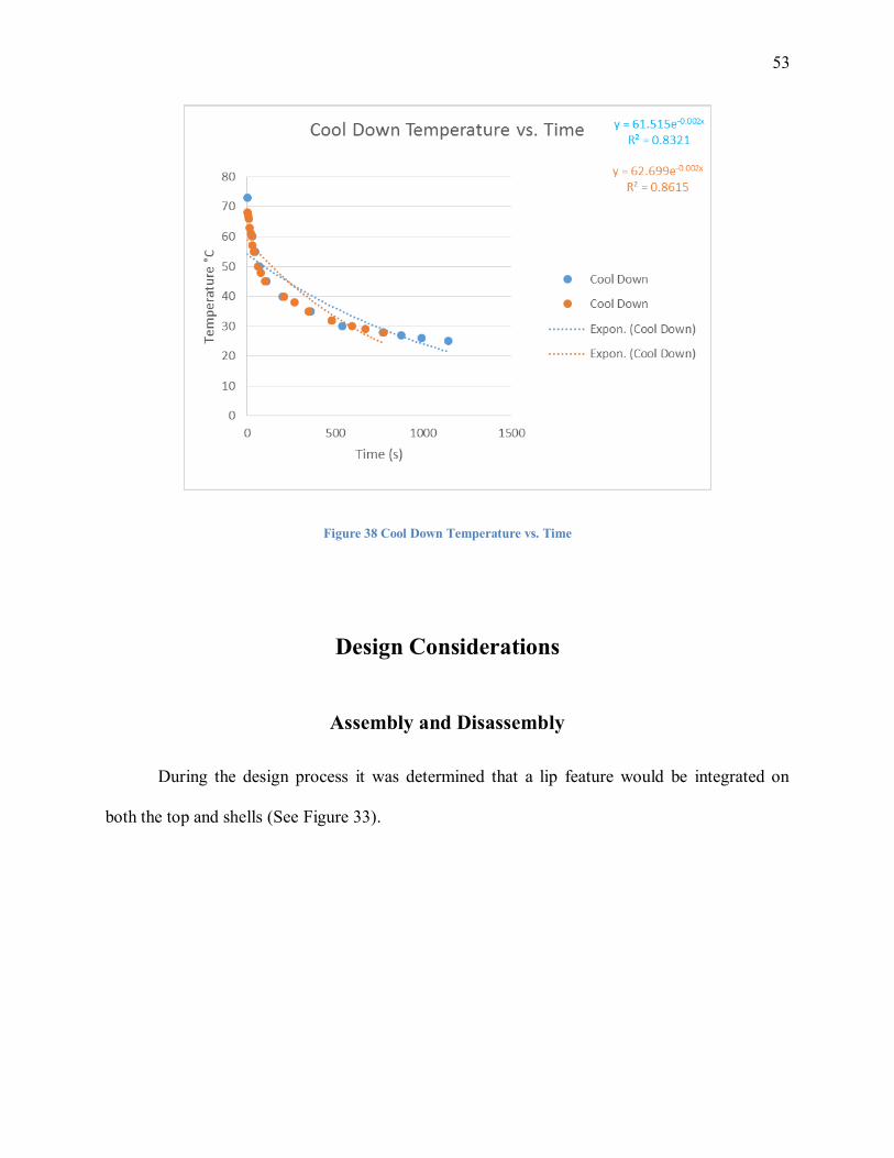
Figure 38 Cool Down Temperature vs. Time
Design Considerations
Assembly and Disassembly
During the design process it was determined that a lip feature would be integrated on
both the top and shells (See Figure 33).

54
Figure 39 Lip Feature and Threads on Top and Bottom Shells
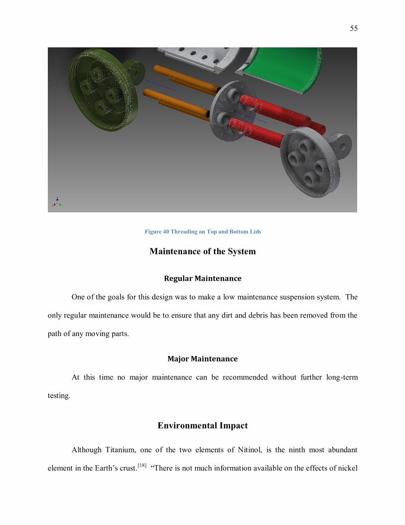
Additionally, the top and bottom lids were threaded, as well as the upper and lower shells that
they were mated to (See Figure 34). This was to ensure easy removal of the top and bottom
shells, which was paramount for access of instrumentation during the experimentation process.
Additionally, it served as a visual confirmation that the components were operating as expected.
Initially the idea was to use an adhesive to join the respective halves of the upper and lower
shells permanently, but that would not have allowed for complete disassembly. Ultimately, only
the upper and lower guide rods were epoxied to their respective lids and the springs were
epoxied to both the lid and slider. This constituted a sub-assembly that could not be
disassembled any further.
55
Figure 40 Threading on Top and Bottom Lids
Maintenance of the System
Regular Maintenance
One of the goals for this design was to make a low maintenance suspension system. The
only regular maintenance would be to ensure that any dirt and debris has been removed from the
path of any moving parts.
Major Maintenance
At this time no major maintenance can be recommended without further long-term
testing.
Environmental Impact
Although Titanium, one of the two elements of Nitinol, is the ninth most abundant
element in the Earth’s crust.[18]
“There is not much information available on the effects of nickel
56
upon organisms other than humans. We do know that high nickel concentrations on sandy soils
can clearly damage plants and high nickel concentrations in surface waters can diminish the
growth rates of algae. Micro organisms can also suffer from growth decline due to the presence
of nickel, but they usually develop resistance to nickel after a while.
For animals nickel is an essential foodstuff in small amounts. But nickel is not only
favorable as an essential element; it can also be dangerous when the maximum tolerable amounts
are exceeded. This can cause various kinds of cancer on different sites within the bodies of
animals, mainly of those that live near refineries. Nickel is not known to accumulate in plants or
animals. As a result nickel will not bio magnify up the food chain.” [18]
Conclusion
Conclusion & Discussion
As is evidenced by the above graphs, the fully martensitic configuration reaches
equilibrium 0.440 ms and the fully austenitic configuration reaches equilibrium in 840ms. Using
logarithmic decrement it was found that the damping ratio was 0.32 for the fully austenitic
configuration. For the fully martensitic configuration logarithmic decrement determined the
damping ratio to be 0.23. This illustrates a conclusive advantage to damping in the martensitic
phase. Due to the complexity of the phase change being coupled with temperature more
equipment, time, and analytical models will be needed to accurately provide usable data.

57
Recommendations & Future Work
In order to proceed with further studies more specialized equipment should be used. The
composition of the material is a key factor in determining the material properties since minor
changes in composition could lead to big changes in transformation temperatures, therefore the
right composition should be studies as well. Also, a better testing fixture should be developed in
order to avoid undesired vibrations.
58
References
1. American Society OF Mechanical Engineers. (1980). Professional ethics and your future a
program for engineering students on professionalism and ethics. [New York], The Society.
2. Barrett, P. and Fridline, D. (2002) "User Implemented Nitinol Material Model in ANSYS",
paper presented at Tenth International ANSYS Conference and Exhibition, Pittsburgh, PA,
Pittsburgh: Computer Aided Engineering Associates, Inc., p.1-6.
3. Dueig, T. et al. (n.p.) Nitinol.
4. Gmj-web.com (n.d.) Untitled. [online] Available at: http://www.gmj-
web.com/resources/upload/products/65610-2.jpg [Accessed: 20 Mar 2013].
5. Img.directindustry.com (n.d.) Untitled. [online] Available at:
http://img.directindustry.com/images_di/photo-m2/crest-to-crest-cs-cms-series-11812-
2838477.jpg [Accessed: 20 Mar 2013].
6. Jensen, D. (2005) Biaxial Fatigue Behavior of NiTi Shape Memory Alloy. Graduate. Air
Force Institute of Technology.
7. Matweb.com (1996) Online Materials Information Resource - MatWeb. [online] Available
at: http://www.matweb.com/ [Accessed: 20 Mar 2013].
8. Nitinol.com (2013) Nitinol materials and components from NDC | Home. [online] Available
at: http://www.nitinol.com [Accessed: 20 Mar 2013].
9. Optimumspring.com (n.d.) Compression Springs Manufacturer - Optimum Spring. [online]
Available at: http://optimumspring.com/products/compression_springs.aspx [Accessed: 20
Mar 2013].
59
10. Pai Mizar, S. (2005) Thermomechanical characterization of NiTiNOL and NiTiNOL based
structures using ACES methodology. Graduate. Worcester Polytechnic Institute.
11. Robertson, S. et al. (2013) Mechanical Fatigue and Fracture of Nitinol. International
Materials Review, 57 (1), p.1-37.
12. Sciencedirect.com (2012) ScienceDirect.com | Search through over 11 million science,
health, medical journal full text articles and books. [online] Available at:
http://www.sciencedirect.com [Accessed: 20 Mar 2013].
13. Simulia.com (n.d.) Optimizing Product Performance with Finite Element Analysis &
Multiphysics Simulation. [online] Available at: http://www.simulia.com [Accessed: 20 Mar
2013].
14. Tinialloy.com (n.d.) Introduction to Shape Memory Alloys. [online] Available at:
http://www.tinialloy.com/intro.htm [Accessed: 20 Mar 2013].
15. Wu, M. and Schetky, L. (2000) "Industrial Applications for Shape Memory Alloys", paper
presented at International Conference on Shape Memory and Superelastic Technologies,
Pacific Grove, CA, p.171-182.
16. Plastics.ides.com. 2013. Acetal (Acetal) Typical Properties Generic Acetal (POM)
Copolymer. [online] Available at: http://plastics.ides.com/generics/2/c/t/acetal-acetal-
properties-processing [Accessed: 26 Sep 2013].
17. Jmmedical.com. 2013. Surface Strains in Nitinol Wire, Ribbon and Sheet - Nitinol Strain
Chart | JMMedical.com. [online] Available at: http://jmmedical.com/resources/271/Surface-
Strains-in-Nitinol-Wire--Ribbon-and-Sheet.html [Accessed: 27 Sep 2013].

60
18. Lenntech.com. 2013. Titanium (Ti) - Chemical properties, Health and Environmental effects.
[online] Available at: http://www.lenntech.com/periodic/elements/ti.htm [Accessed: 24 Nov
2013].

61
Appendix A: Experimental Equipment
1. Convergence Instruments | Vibration Sentry RT 128 | 3-axis ± 16g MEMS accelerometer
2. Omega | BARE-20-J-12 | Bare Wire Type-J Thermocouple
62
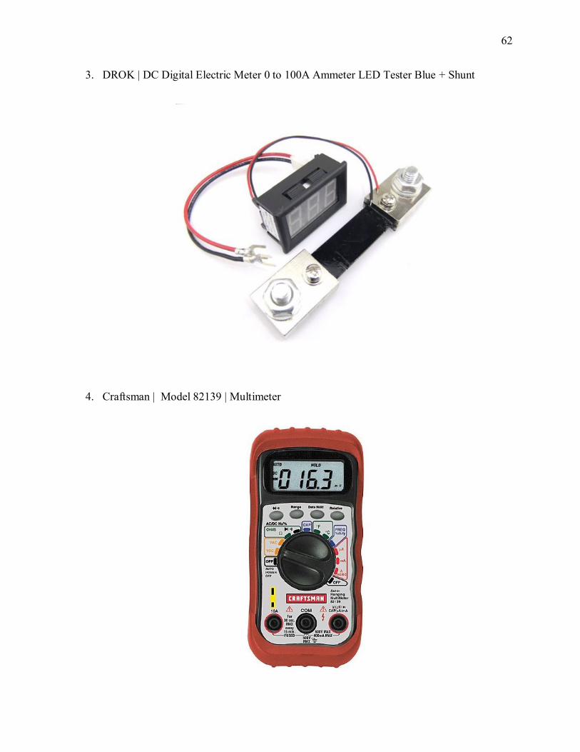
3. DROK | DC Digital Electric Meter 0 to 100A Ammeter LED Tester Blue + Shunt
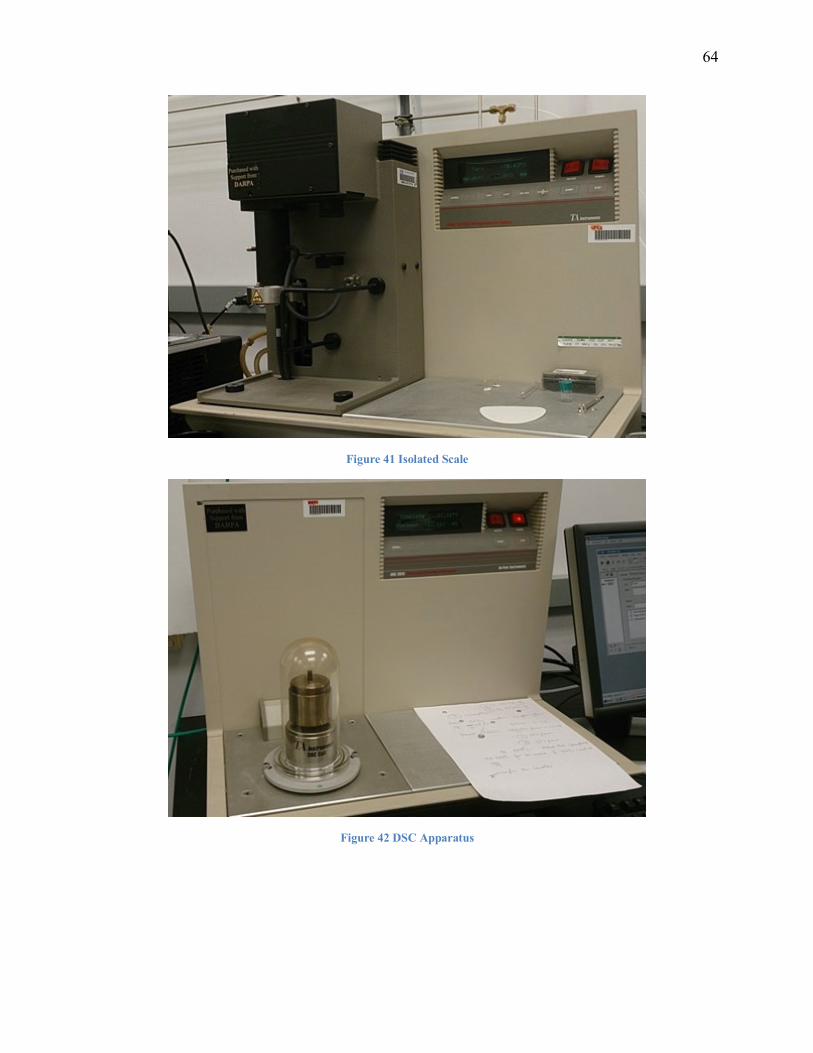
4. Craftsman | Model 82139 | Multimeter

63
5. Schumacher | XP500 | Jump Starter
6. DSC courtesy of Florida International University Department of Mechanical & Materials
Engineering
64
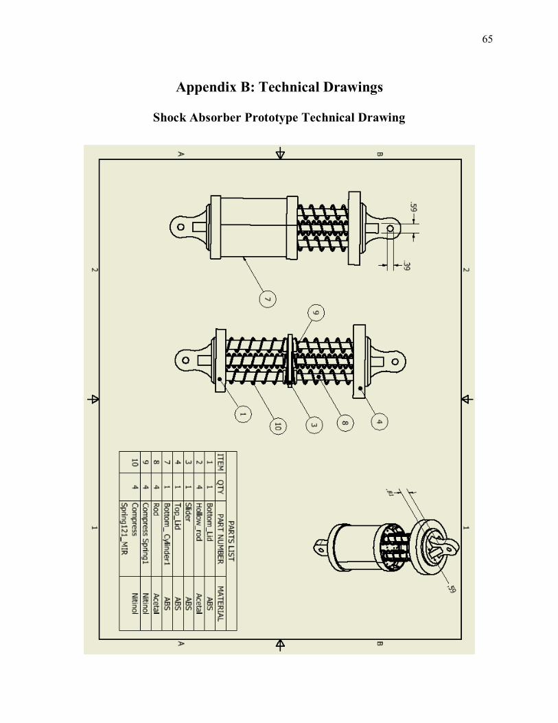
Figure 41 Isolated Scale
Figure 42 DSC Apparatus
65
Appendix B: Technical Drawings
Shock Absorber Prototype Technical Drawing
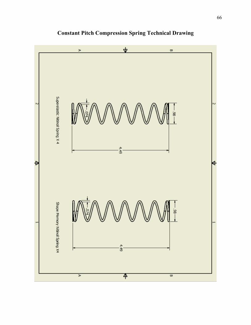
66
Constant Pitch Compression Spring Technical Drawing
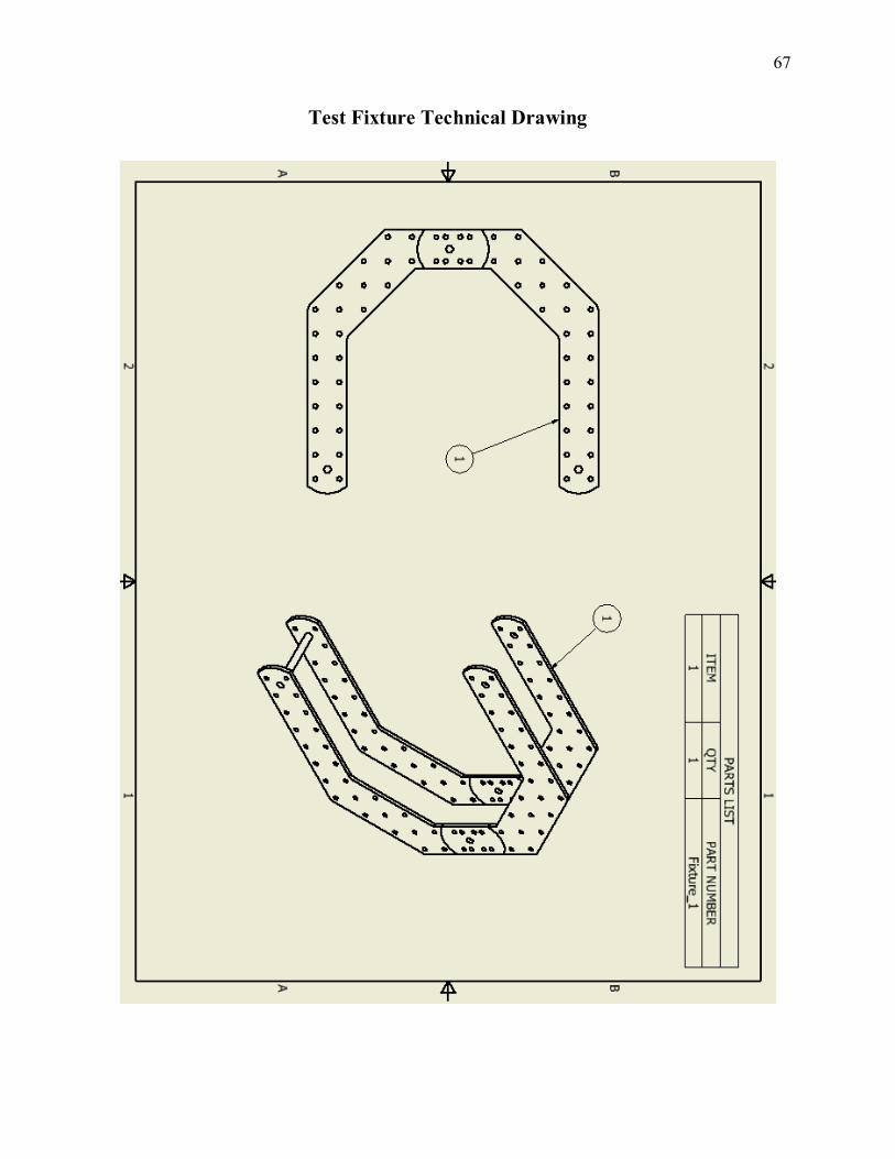
67
Test Fixture Technical Drawing
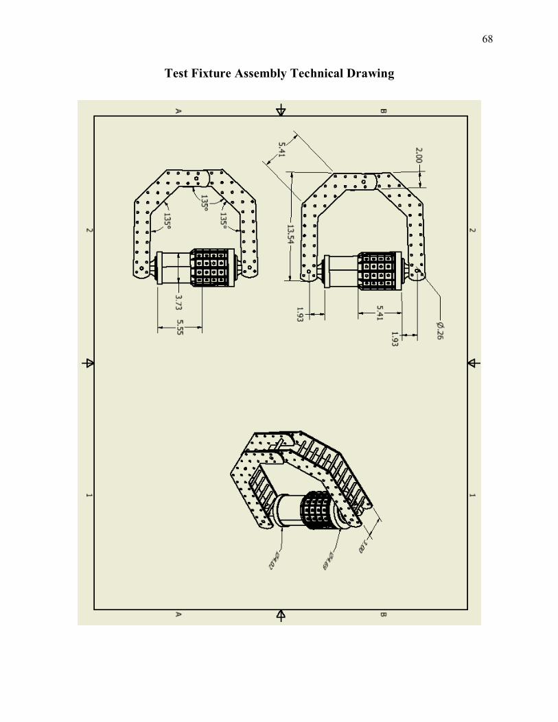
68
Test Fixture Assembly Technical Drawing