REPLACES: 24.07.10 NB7FI05SY / NBFI05SY REVISED: … · fiat ducato 10/14on 76mm series 2 nudge bar...
18
. © Copyright – ECB Pty Ltd – 2015 1 NB7FI05SY / NBFI05SY FIAT DUCATO 76mm SERIES 2 NUDGE BAR and 76mm NUDGE BAR To the Fitter, This instruction covers two models of this vehicle. The difference between the models are easily seen in the headlights of the vehicles. There is also a change in the earlier model to the bumper support which is unseen from the vehicles exterior. This instruction and the associated ECB Protection Bars have been designed to allow fitment to the various changes which Fiat have affected to this vehicle. Due to the changes in the external parts of the vehicle, the placement of the cuts in the bumper is different from one model to the next. Please use the instruction which corresponds to the vehicle you are fitting. For Vehicles within year models 01/12 to 10/14 follow instructions on pages 3 to 8, Steps 1 to 12 For Vehicles year model 10/14on follow instructions on pages 9 to 13, Steps 13 to 25. NOTE: bolt kit is the same for both instructions. FITTING KIT 1 – Pair ECB steel mounting brackets 20 – M10 flat washers 8 – M10 x 1.25 x 35 bolts 14 – M10 spring washers 2 – M10 x 1.25 x 35 bolt only on 300mm wire 8 – M10 x 1.25 nuts 4 – M10 x 1.25 x 40 bolts REPLACES: 24.07.10 REVISED: 22.01.15
Transcript of REPLACES: 24.07.10 NB7FI05SY / NBFI05SY REVISED: … · fiat ducato 10/14on 76mm series 2 nudge bar...
. © Copyright – ECB Pty Ltd – 2015 1
NB7FI05SY / NBFI05SY
FIAT DUCATO 76mm SERIES 2 NUDGE BAR and 76mm NUDGE BAR
To the Fitter, This instruction covers two models of this vehicle. The difference between the models are easily seen in the headlights of the vehicles. There is also a change in the earlier model to the bumper support which is unseen from the vehicles exterior. This instruction and the associated ECB Protection Bars have been designed to allow fitment to the various changes which Fiat have affected to this vehicle. Due to the changes in the external parts of the vehicle, the placement of the cuts in the bumper is different from one model to the next. Please use the instruction which corresponds to the vehicle you are fitting. For Vehicles within year models 01/12 to 10/14 follow instructions on pages 3 to 8, Steps 1 to 12 For Vehicles year model 10/14on follow instructions on pages 9 to 13, Steps 13 to 25. NOTE: bolt kit is the same for both instructions. FITTING KIT 1 – Pair ECB steel mounting brackets 20 – M10 flat washers 8 – M10 x 1.25 x 35 bolts 14 – M10 spring washers 2 – M10 x 1.25 x 35 bolt only on 300mm wire 8 – M10 x 1.25 nuts 4 – M10 x 1.25 x 40 bolts
REPLACES: 24.07.10REVISED: 22.01.15

. © Copyright – ECB Pty Ltd – 2015 2

. © Copyright – ECB Pty Ltd – 2015 3
FITTING INSTRUCTIONS
FIAT DUCATO 1/12 to 10/14 76mm SERIES 2 NUDGE BAR and 76mm NUDGE BAR
VEHICLE FRONTAL PROTECTION SYSTEM (VFPS) FOR AIR BAG & ADR COMPLIANT VEHICLES
Check installation hardware before commencing. Special Requirements: T25 and T30 Torx bits and appropriate driver Vehicle mounting Specifics: This vehicle has two types of front bumper support. See figure 1and 2 for different bumper supports. Depending on support type, removal from vehicle will be required.
1. Lift bonnet. Bonnet latch on passengers side at end of dash in door opening. 2. Remove four T30 Torx bolts from top of grille and two T30 plastic screw clips from bottom of grille. Gently
lift grille to remove taking care to lift vertically from plastic retaining clips.
3. Behind grille remove twelve T30 Torx bolts, and four T30 Torx bolts under front of bumper. Remove centre plastic section of bumper. Remove front underside bolts from bumper side sections.
4. Drop front of under body guard by removing two T25 Torx screws from lower inner guard and nine PK
screws across underside of bumper. Allow to hang. See figure 5.
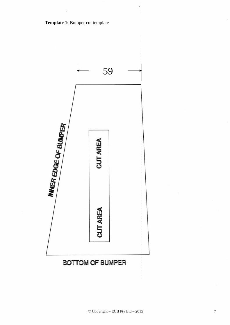
5. Mask lower inner corners of bumper plastic side panels with paper style tape. Using sharp scissors, cut carefully around template supplied. Place template onto lower corner of bumper opening, align sides to suit bumper edges and trace centre cut out onto masked area. Turn template over and repeat for other side. See figures 6 and 7.
6. FOR NARROW BUMPER SUPPORT (large holes): Remove three 15mm head bolts (per side) on front of
chassis rail and loosen only one 15mm head nut at top outer corner of front of chassis rail to allow bumper support to float on chassis rails. Completing one side at a time, remove 15mm head nut previously loosened, fit ECB steel mounting brackets (supplied) between front of chassis rail and bumper support, tag on bar fitment area to inside of bumper on front of support. See figure 8. As this is a tight fit, the best method is to bring mounts up from under vehicle, clip onto bumper support and place onto outer stud. Replace original 15mm nut. Complete both mounts, then finish bolting in place using three M10 x 35 x 1.25 bolts, spring washers and flat washers (per side) (supplied). FINGER TIGHTEN ONLY. Using steel mounting bracket as a guide, drill 10mm hole through lower flange or front of bumper support. See figure 8. Blow all filings clear and treat all exposed metal with a rust inhibitor. Fit M10 x 35 bolts, flat washers, spring washers and nuts (supplied). TIGHTEN ALL BOLTS.
7. FOR WIDE BUMPER SUPPORT (multiple smaller holes): Remove two T30 torx head bolts from lower
corners of outer bumper areas. Remove three 15mm head bolts (per side) on front of chassis rail and one 15mm head nut at top outer corner of front of chassis rail. Drop bumper support down and remove from vehicle. On bench, align ECB steel mounting brackets to rear holes in bumper support with attachment tab to inside of crash cans. Using ECB steel mounting brackets as a guide, drill hole in crash can to 10mm. See figure 9 and 10. Blow all filings clear and treat all exposed metal with a rust inhibitor From rear hole in bumper support, hammer internal plate to outside of mount and install M10 x 35 bolt on wire to previously drilled hole. Tighten enough for mount to not move on bumper support when lifted. Trim wiring from bolt and wind tail into hole in rear of ECB steel mount. Refit bumper support to vehicle.

. © Copyright – ECB Pty Ltd – 2015 4
8. Align steel mounting brackets using outside measurement of alloy mounts on ECB protection bar to inner measurement of steel mounting brackets as a guide. Centralise steel mounting brackets to vehicle and TIGHTEN ALL BOLTS.
9. Refit plastic bumper centre and grille to vehicle and bumper sides using original T30 Torx bolts.
10. Fit protection bar to steel mounting brackets using four M10 x 40 bolts, flat washers, spring washers and nuts
(supplied). Finger tighten only.
11. Align protection bar with vehicle. See figures 10 and 11 for 76mm Series 2 Nudge Bar and figures 12 and 13 for 76mm Nudge Bar. TIGHTEN ALL BOLTS.
12. Refit under body guard to vehicle using original T25 Torx screws. Do not over tighten as this will strip
retaining lugs in support.
ENSURE NUMBER PLATE IS CLEARLY VISABLE
Note: When fitting/refitting the licence plate to the vehicle, ensure there is no obstruction to licence plate vision in accordance with local authorities. If required relocate licence plate to an alternate location.
Further VFPS Notes: a) Do not attach VFPS to the vehicle using anchorages not intended for this purpose (e.g. engine mounting bolts). b) Do not use this product for any vehicle make or model, other than those specified by the VFPS manufacturer. c) Do not remove the plaque or label from the VFPS. d) Do not modify the structure of the VFPS in any way. e) No accessory or fitment should project forward of the VFPS forward profile. f) ENSURE THESE INSTRUCTIONS ARE LEFT WITH VEHICLE OWNER AND/OR OPERATOR.
IMPORTANT INFORMATION Periodically check bolts and nuts for correct tightness, especially if travelling on rough roads
Figure 1 – Earlier model bumper support Figure 2 – Later model bumper support. Note hole size in centre.
. © Copyright – ECB Pty Ltd – 2015 5
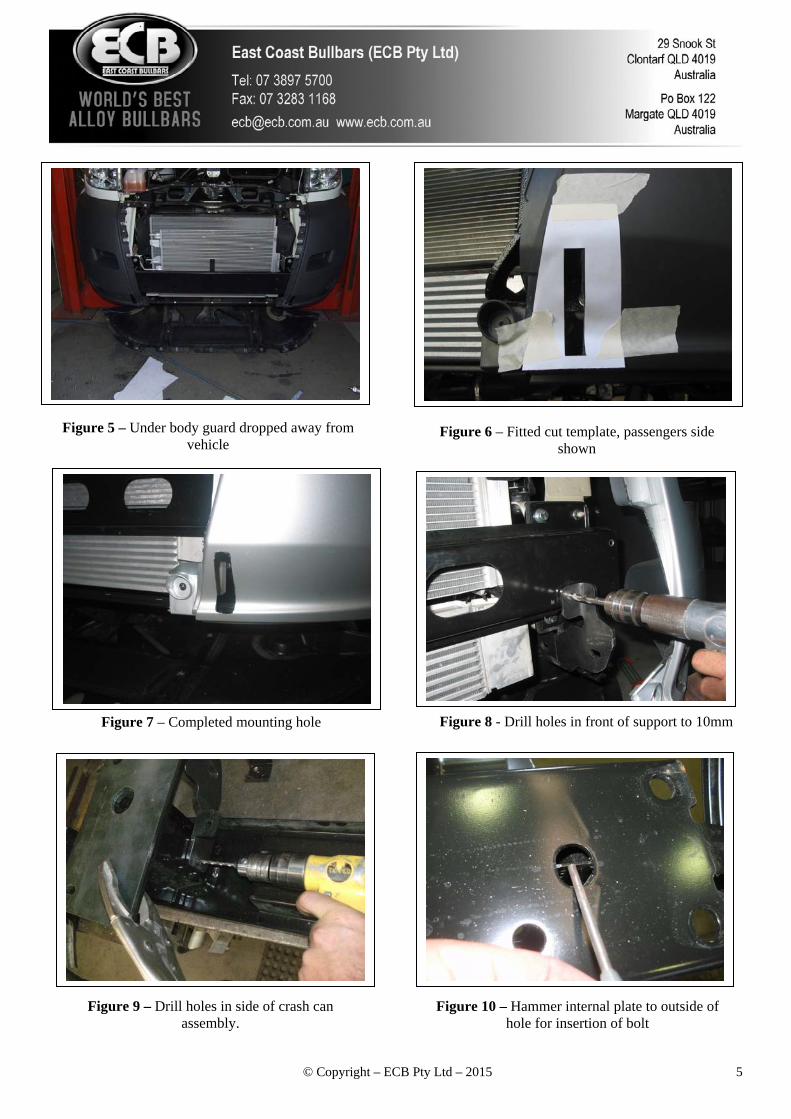
Figure 5 – Under body guard dropped away from vehicle
Figure 6 – Fitted cut template, passengers side shown
Figure 8 - Drill holes in front of support to 10mm
Figure 7 – Completed mounting hole
Figure 10 – Hammer internal plate to outside of hole for insertion of bolt
Figure 9 – Drill holes in side of crash can assembly.

. © Copyright – ECB Pty Ltd – 2015 6
Figure 10 – Series 2 Nudge Bar front view shown Figure 11 – Series 2 Nudge Bar side view shown
Figure 12 – Nudge bar front view shown Figure 13 – Nudge Bar side view shown
. © Copyright – ECB Pty Ltd – 2015 7
Template 1: Bumper cut template
59

. © Copyright – ECB Pty Ltd – 2015 8

. © Copyright – ECB Pty Ltd – 2015 9
FITTING INSTRUCTIONS
FIAT DUCATO 10/14on 76mm SERIES 2 NUDGE BAR and 76mm NUDGE BAR
VEHICLE FRONTAL PROTECTION SYSTEM (VFPS) FOR AIR BAG & ADR COMPLIANT VEHICLES
Check installation hardware before commencing. Special Requirements: T25 and T30 Torx bits and appropriate driver Vehicle mounting Specifics: This vehicle has two types of front bumper support. See figure 1and 2 for different bumper supports. Depending on support type, removal from vehicle will be required.
13. Lift bonnet. Bonnet latch on passengers side at end of dash in door opening. 14. Remove two T30 Torx head bolts from top of headlights. Disconnect headlight wiring. Slide to inside of
vehicle to remove. 15. Remove eight T30 Torx bolts from top of grille and two T30 plastic screw clips from bottom of grille. Gently
lift grille to remove taking care to lift vertically from plastic retaining clips. CAUTION: forward sliding of grille, will break clips.
16. Behind grille remove twelve T30 Torx bolts, and four T30 Torx bolts under front of bumper. Remove centre
plastic section of bumper. Remove front underside bolts from bumper side sections.
17. Drop front of under body guard by removing two T25 Torx screws from lower inner guard and nine screws across underside of bumper. Allow to hang. See figure 3.
18. Mask lower inner corners of bumper plastic side panels with paper style tape. Using sharp scissors, cut
carefully around template supplied. Place template onto lower corner of bumper opening, align sides to suit bumper edges and trace centre cut out onto masked area. Turn template over and repeat for other side. See figures 4 and 5.
19. FOR NARROW BUMPER SUPPORT (large holes): Remove three 15mm head bolts (per side) on front of
chassis rail and loosen only one 15mm head nut at top outer corner of front of chassis rail to allow bumper support to float on chassis rails. Completing one side at a time, remove 15mm head nut previously loosened, fit ECB steel mounting brackets (supplied) between front of chassis rail and bumper support, tag on bar fitment area to inside of bumper on front of support. See figure 6. As this is a tight fit, the best method is to bring mounts up from under vehicle, clip onto bumper support and place onto outer stud. Replace original 15mm nut. Complete both mounts, then finish bolting in place using three M10 x 35 x 1.25 bolts, spring washers and flat washers (per side) (supplied). FINGER TIGHTEN ONLY. Using steel mounting bracket as a guide, drill 10mm hole through lower flange or front of bumper support. See figure 8. Blow all filings clear and treat all exposed metal with a rust inhibitor. Fit 3/8 x 1 ½ bolts, flat washers, spring washers and nuts (supplied). TIGHTEN ALL BOLTS.
20. FOR WIDE BUMPER SUPPORT (multiple smaller holes): Remove two T30 torx head bolts from lower
corners of outer bumper areas. Remove three 15mm head bolts (per side) on front of chassis rail and one 15mm head nut at top outer corner of front of chassis rail. Drop bumper support down and remove from vehicle. On bench, align ECB steel mounting brackets to rear holes in bumper support with attachment tab to inside of crash cans. Using ECB steel mounting brackets as a guide, drill hole in crash can to 10mm. See figure 7 and 8. Blow all filings clear and treat all exposed metal with a rust inhibitor From rear hole in bumper support, hammer internal plate to outside of mount and install M10 x 35 bolt on wire to previously

. © Copyright – ECB Pty Ltd – 2015 10
drilled hole. Tighten enough for mount to not move on bumper support when lifted. Trim wiring from bolt and wind tail into hole in rear of ECB steel mount. Refit bumper support to vehicle.
21. Align steel mounting brackets using outside measurement of alloy mounts on ECB protection bar to inner
measurement of steel mounting brackets as a guide. Centralise steel mounting brackets to vehicle and TIGHTEN ALL BOLTS.
22. Refit plastic bumper centre and grille to vehicle and bumper sides using original T30 Torx bolts.
23. Fit protection bar to steel mounting brackets using four M10 x 40 bolts, flat washers, spring washers and nuts
(supplied). Finger tighten only.
24. Align protection bar with vehicle. See figures 9 and 10 for 76mm Series 2 Nudge Bar and figures 11 and 12 for 76mm Nudge Bar. TIGHTEN ALL BOLTS.
25. Refit under body guard to vehicle using original T25 Torx screws. Do not over tighten as this will strip
retaining lugs in support.
ENSURE NUMBER PLATE IS CLEARLY VISABLE
Note: When fitting/refitting the licence plate to the vehicle, ensure there is no obstruction to licence plate vision in accordance with local authorities. If required relocate licence plate to an alternate location.
Further VFPS Notes: a) Do not attach VFPS to the vehicle using anchorages not intended for this purpose (e.g. engine mounting bolts). b) Do not use this product for any vehicle make or model, other than those specified by the VFPS manufacturer. c) Do not remove the plaque or label from the VFPS. d) Do not modify the structure of the VFPS in any way. e) No accessory or fitment should project forward of the VFPS forward profile. f) ENSURE THESE INSTRUCTIONS ARE LEFT WITH VEHICLE OWNER AND/OR OPERATOR.
IMPORTANT INFORMATION
Periodically check bolts and nuts for correct tightness, especially if travelling on rough roads
Figure 1 – Earlier model bumper support Figure 2 – Later model bumper support. Note hole size in centre.

. © Copyright – ECB Pty Ltd – 2015 11
Figure 3 – Under body guard dropped away from vehicle
Figure 4 – Fitted cut template, drivers side shown
Figure 6 - Drill holes in front of support to 10mm
Figure 5– Completed mounting hole
Figure 8 – Hammer internal plate to outside of hole for insertion of bolt
Figure 7 – Drill holes in side of crash can assembly.

. © Copyright – ECB Pty Ltd – 2015 12
Figure 9 –Nudge Bar front view shown Figure 10 –Nudge Bar side view shown
Figure 11 – Series 2 Nudge bar front view shown Figure 12 – Series 2 Nudge Bar side view shown

. © Copyright – ECB Pty Ltd – 2015 13
Template 1: Bumper cut template

. © Copyright – ECB Pty Ltd – 2015 14

. © Copyright – ECB Pty Ltd – 2015 15
We value your comments Dear Fitter, ECB would like to know how you went with the installation of this product. We value your comment and may need to contact you to clarify some details so please complete your contact details clearly. We would appreciate if you could complete as many of the following details as possible. Your Name:
Your contact No.
Product Part No.
Product Invoice No.
Product Description:
Make, model, and year of vehicle:
Product Work Order No.
Company your from/Company product purchased from:
Date of Fitment: ____/____/____ Yes No Was the fitting hardware supplied complete? If no what was not supplied __________________________________________________________________________________________________________________________________________________________________________________________________________________________________________________________________ Yes No Did the installation go well? Please provide comments
________________________________________________________________________________________________________________________________________________________________________________________________________________________________________________________________________________________________________________________________________________________ Please draw diagrams if you need to. Post to Fax to Reply Paid 122 (07) 3283 1168 PO Box 122 Margate QLD 4019

. © Copyright – ECB Pty Ltd – 2015 16
. © Copyright – ECB Pty Ltd – 2015 17
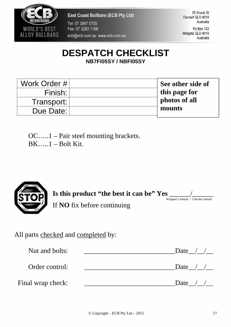
DESPATCH CHECKLIST NB7FI05SY / NBFI05SY
Work Order # Finish:
Transport: Due Date:
OC…..1 – Pair steel mounting brackets. BK…..1 – Bolt Kit.
All parts checked and completed by:
Nut and bolts: __________________________Date__/__/__
Order control: __________________________Date__/__/__ Final wrap check: __________________________Date__/__/__
Is this product “the best it can be” Yes ______/______ Wrapper’s initials / Checker initials
If NO fix before continuing
See other side of this page for photos of all mounts

. © Copyright – ECB Pty Ltd – 2015 18