Repeaters, Networks and Remote stations · 2019-12-02 · capable repeaters with analogue FM radios...
56
Repeaters, Networks and Remote stations
Transcript of Repeaters, Networks and Remote stations · 2019-12-02 · capable repeaters with analogue FM radios...

Repeaters, Networks and Remote stations

A bit of History
• Repeaters became popular in the 1960’s with improvements in technology
• The move to the higher VHF and UHF bands with smaller coverage areas created a need for a way to improve the coverage over simplex.
• First systems used separate antennas and individual transmitters and receivers.
• Later systems use single or separate antennas with multiple radio systems sharing them

Nova Scotia Integrated Mobile Radio System
(NSIMRS)
• VHF and UHF analogue repeater systems peaked in popularity in the late 1970’s to early 2000’s.
• The NSIMRS consisted of five separate but linkable VHF repeater systems for DNR, DOT, EHS, Fire dept. and Government.
• The system had 25 sites and expanded to 31 to fill in coverage gaps


NSIMRS Console at
Shubie
All interdepartmental linking could be
controlled from here.

Microwave Linking
• The Radio system was linked together through microwave links at each radio site.
• Sites that were added on (usually for DOT) would link back to a microwave site via a UHF link.

Typical DOT satellite repeater
• VHF Transmitter
• 60W continuous operation.

Typical DOT satellite repeater
• VHF Receiver
• Has CTCSS tone decoder and tone generator for voting unit at master site
Typical DOT satellite repeater
• UHF Transmitter
• 5W continuous output
• Transmits 24/7
• Continuous TX eliminates switching delays

Typical DOT satellite repeater
• UHF Duplexer
• Combines UHF transmitter and receiver into a single Yagi antenna aimed at the master site.
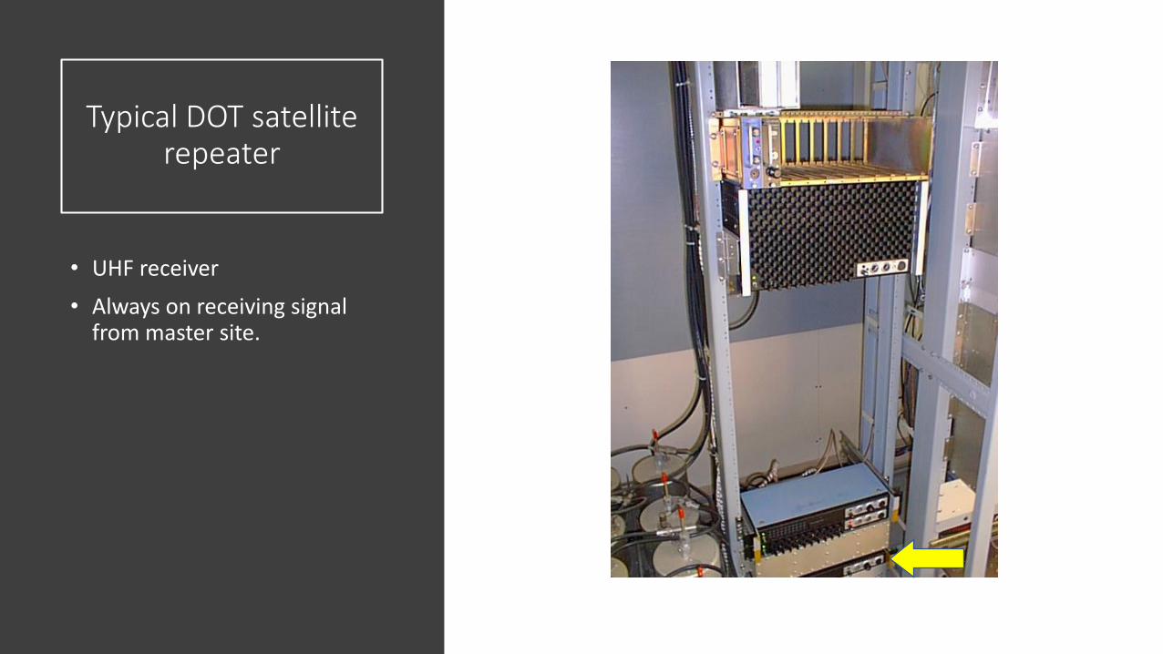
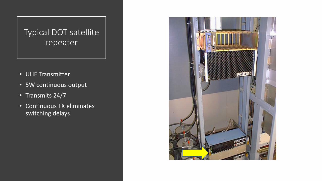
Typical DOT satellite repeater
• UHF receiver
• Always on receiving signal from master site.

DOT VHF VOTINGSYSTEM
• To help with coverage satellite sites were added for the DOT to help fill in the coverage holes around the province.
• The VHF receivers contained a tone generator to generate a high frequency audio tone. The tone frequency would vary with the received signal strength and the voting unit at the master site would pick the best one to repeat to the VHF transmitters and switch the audio paths accordingly.
• The VHF receivers were all on the same frequency, the VHF transmitters were on different frequency's –Not able to work for amateur radio!

The End of an Era
• After 2000 and the introduction of TMR the VHF system was mostly replaced.
• The Fire Dept and “Government” repeaters live on.

Repeaters and Amateur
Radio

Amateur Radio
Repeaters
• Typically small installations using surplus commercial equipment.
• May have linking to a wider system using DTMF codes and UHF links.
• Repeater uses a controller for Identification and linking.
• In Canada repeaters ID ever 30 minutes.

Amateur Radio
Repeaters
• DTMF – Dual Tone Multiple Frequency. Example touch tone phone
• CTCSS – Continuous tone coded squelch system. Uses a sub-audible tone to allow repeater access.
• Example CTCSS tones 82.5 Hz, 71.9 Hz, 151.4 Hz
• DCS – Digitally Coded Squelch. Uses digital data instead of tones. DCS codes are numbers.

Amateur Radio
Repeaters
• On 2 meters the repeater split or offset is 600Khz
• On 70cm the offset is usually 5Mhz
• On 6m the offset is 1Mhz
• The receive frequency of the repeater can be offset above or below the transmit frequency depending on where it is in that band segment

Simple Repeater
• Single antenna
• Duplexer allows sharing of the antenna
• Receive and transmit is possible simultaneously


VE1HCA Willow Hill
• Installed in May 2019 in NSIMRS site at Willow Hill
• Consists or 100W Motorola Micor and an RLC controller
• Radio site has two antennas. One for RX, one for TX.

VE1HCA Willow Hill Tower
• VHF Receive antenna is on the top, the VHF Transmit antenna is below about ¾ the way up.
• Round white domes are microwave dishes with radomes and ice protection over top.

VE1HCA Willow Hill Repeater Controller
• Controls all repeater operations
• Has internal clock and voice module for announcing the time.
• Can be expanded to allow linking to other sites.

VE1HCA Willow HillMotorola Micor
100W RF amplifier
• Amplifies exciter output from transmitter (450 mW) to 100W
• Capable of continuous operation at 100W

VE1HCA Willow Hill Motorola Micor
• Contains the transmitter and receiver sections
• Has shelf in middle for option cards – not usually used
• Crystal controlled

VE1HCA Willow Hill Motorola MicorPower Supply
• 12V @ 35A power supply
• Supply's all other voltages for repeater

VE1HCA MulticouplerSystem
• Allows the repeater to share the site antennas with the other existing equipment.
• Must be tuned with Correct and accurate test equipment!!!
• Top is Receive bottom is Transmit

MulticouplersBand Pass
• A tunable cavity with an input and output connector.
• Loops can be turned to adjust insertion loss.
• Insertion loss is how much energy is lost in the cavity measured in Decibels.

MulticouplersNotch
• A tunable cavity with an input only.
• Loop can be turned to maximize notch
• Typically can achieve 25DB of notch in one can.


Duplexers and Multicouplers
• Bandpass and notch cavity's are combined together and can be configured into duplexers or multicouplers to allow for expansion later.
• A terminator resistor must be on the end of the multicoupler chain for proper operation.
• Special “Q” notches can be added to bandpass cavity's for notching in systems with close spacing (600khz)
• Isolation between the receive and transmit frequency's should be in excess of 80 dB to prevent de-sensing of the receiver.

VE1CDN
• MulticouplerRacks at VE1CDN

Controllers
• Typical Arcom RC210 Controller

Controllers
• Controls all the repeater functions except squelch
• Can be programmed to allow for another repeater or link transceiver to be connected –usually UHF link to network
• Controller has “ports”. Generally the connection to each repeater or link radio
• Each port has connections for a PTT signal, Transmit audio, receive audio, and a COR or receive signal. May have other options as well depending on controller.

Controllers
• Most modern controllers have built in audio announcements and time clocks.
• They can be programmed remotely via radio link or onsite with a PC.
• Early controllers were basic CW ID and maybe some audio control.


MAVCOM repeater system


MAVCOM Repeater System
• Maritime Amateur Voice Communications System
• The MAVCOM Link System is comprised of 48 VHF and UHF repeaters in Nova Scotia and Prince Edward Island. These repeaters can be linked together, either selectively or as a whole.
• The linking system is designed in a way similar to our own nervous system. There is a central trunk or “backbone” that runs throughout each of the provincial systems. The individual repeaters that are part of the linking system are located along the trunk but are normally not connected to the trunk.

MAVCOM Repeater System
• A simple four-digit code can be entered using the DTMF keypad on a 2-meter radio and the repeater can be linked into that “backbone”. Now, a second four-digit code can be entered, and this will link the first repeater (now on the backbone) into a distant repeater. A few of the repeaters on the system have what is called “one code to destination” access; this means instead of first having to link into the backbone and then into the distant repeater, a single code will get you to the distant repeater.
• When using the repeater linking system you must key up for about one second before speaking or your first syllable or word will not be transmitted. Also when it is your turn to speak, you should pause before keying up in order to allow timers throughout the system to reset.

Using the MAVCOM system
1. First, monitor the repeater for 30 seconds or so to see if it is in use.
2. Give your call sign and announce your intention to up link. – “This is VE1XXX up-linking”
3. Push the appropriate buttons on your tone pad to turn the local repeater onto the backbone. Check to see if the link is in use by another repeater, then identify the destination repeater and yourself – VE1SPR – VE1XXX and then dial the code for the repeater you wish to reach.
Note: It is normally necessary to hold the PTT switch down during this step.

Using the MAVCOM system
4. Listen for the CW or Voice identifier that is broadcast by the distant repeater to verify you have reached the correct machine.
5. Listen again. You may have dropped in on a conversation taking place on the distant repeater. If this happens, wait until the operators acknowledge your presence and invite you to make your call. Be courteous, because a QSO in progress has priority.
6. If your call is not answered, or at the end of your conversation, give your call sign and announce your intention to downlink – “VE1XXX down-linking”.

Using the MAVCOM system
7. Push the appropriate buttons on your tone pad to first turn off the distant repeater and then disconnect your repeater from the backbone.
8. Give your call sign and announce your intentions – “VE1XXX clear of the link”
9. Multiple repeaters can be linked simultaneously in NS and PEI. You first link the backbone as outlined above, Then link the other repeaters by dialing their destination codes one after the other; un-key between each code.
10. Finally, PLEASE remember to turn off any repeaters you turn on, including the local repeater. This avoids tying up the link system and leaves it ready for the next user.
11. Courtesy is mandatory; a maximum 10-minute conversation time (except for nets) is suggested to allow access by others.

Echolink
• EchoLink® software allows licensed Amateur Radio stations to communicate with one another over the Internet, using streaming-audio technology. The program allows worldwide connections to be made between stations, or from computer to station, greatly enhancing Amateur Radio's communications capabilities. There are more than 200,000 validated users worldwide — in 151 of the world's 193 nations — with about 6,000 online at any given time.


http://www.echolink.org/

Echolink and Raspberry Pi
• Your two choices for Echolink on the Pi are SVXLink http://www.svxlink.org/ or AllStarlinkhttps://allstarlink.org/getstarted.html both work well on the RasPi 3b but AllStarLinkalthough a bit more complex for initial setup is a lot more versatile and gives you access to the AllStarLink network and features like access to the network from a VOIP phone.

IRLP – Internet Linking Radio
Project
• The aim of this project is to reliably and inexpensively link amateur radio systems without the use of RF links, leased lines, or satellites.
• The IRLP uses Voice-Over-IP (VoIP) custom software and hardware. Coupled with the power of the Internet, IRLP will link your repeater site or simplex station to the world in a simple and cost effective way.
• IRLP operates a worldwide network of dedicated servers and nodes offering very stable worldwide voice communications between hundreds of towns and cities. All this with unsurpassed uptimes and the full dynamic range of telephone quality audio.

http://www.irlp.net/

MMDVM

MMDVM -Multi-Mode Digital Voice
Modem
• The MMDVM is intended to be an open-source Multi-Mode Digital Voice Modem, which utilities the power of an ARM processor and a simple analogue interface board. The Multi-Mode Digital Voice Modem is a combined hardware and software development of a modem to handle all amateur digital voice modes. Initially it will support D-Star and DMR, with System Fusion and P.25 coming later, as well as a built-in FM repeater controller. For all modes other than DMR and FM, the modem can be used in simplex or duplex mode, while for DMR and FM full duplex must be used.

MMDVM
• MMDVM boards can be used to make digital capable repeaters with analogue FM radios
• MMDVM can also be used to create a “hotspot” that connects to a digital network over IP link and facilitates use of a handheld radio on the move.
• Hotspots can be low power (10mW) or high power using a simplex analogue FM radio.

MMDVM Hotspot

MMVDM repeater board- ZumSpot

ZUM SPOT Repeater on Raspberry pi

Questions?