Remedial Action Report for Waste Area Group Operable … · This comprehensive Remedial Action...
27
PO RTAG E-05-002 Revision 1 Remedial Action Report for Waste Area Group 9, Operable Unit 9-04 at the Idaho National Laboratory June 2005
Transcript of Remedial Action Report for Waste Area Group Operable … · This comprehensive Remedial Action...
PO RTAG E-05-002 Revision 1
Remedial Action Report for Waste Area Group 9, Operable Unit 9-04 at the Idaho National Laboratory
June 2005
PORTAGE-05-002 Revision 1
Remedial Action Report for Waste Area Group 9, Operable Unit 9-04 at the Idaho
National Laboratory
June 2005
Portage, Inc. Idaho Falls, Idaho 83402
Prepared under Portage Contract Number 00041 165 Portage Project Number 2087.00 for Batelle Energy Alliance under
US Department of Energy Prime Contract Number DE-AC07-051D14517
This page intentionally left blank.
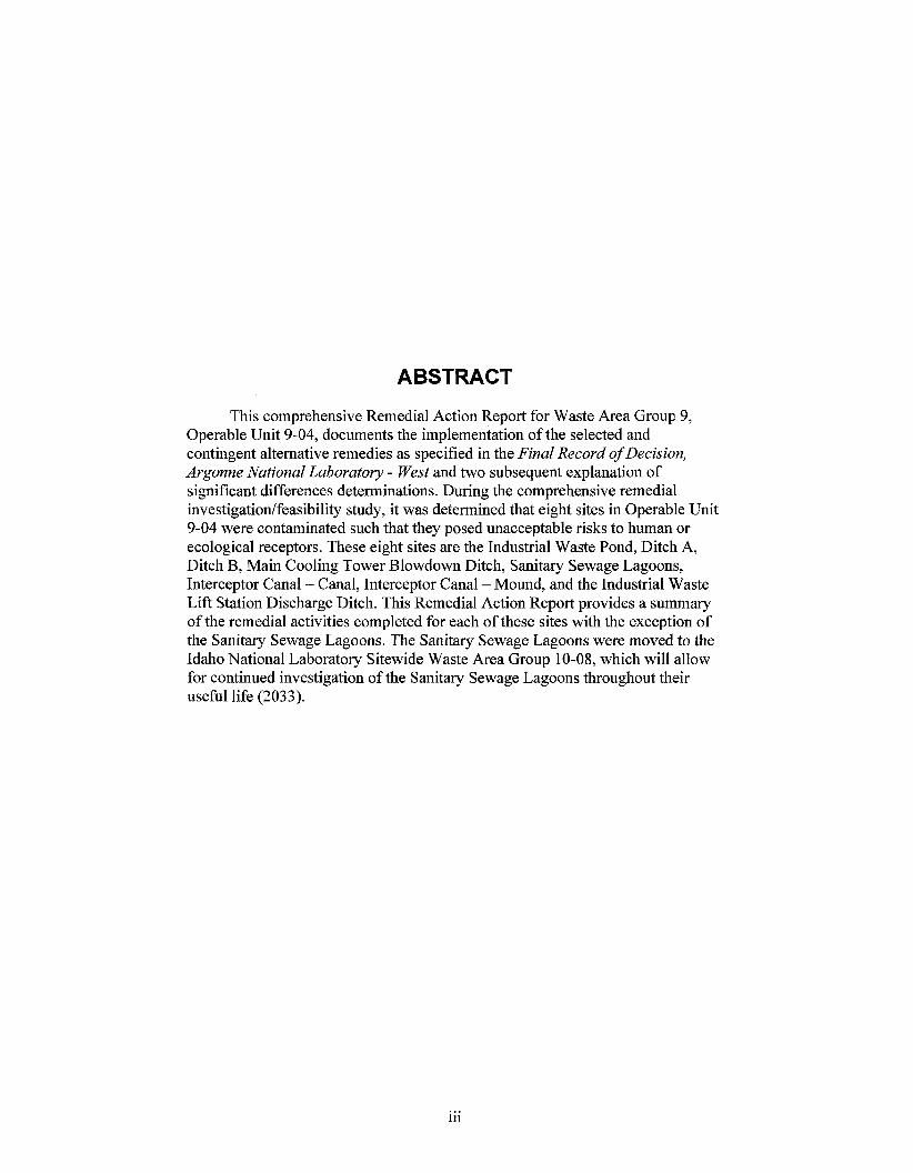
This comprehensive Remedial Action Report for Waste Area Group 9, Operable Unit 9-04, documents the implementation of the selected and contingent alternative remedies as specified in the Final Record ofDecision, Argonne National Laboratory - West and two subsequent explanation of significant differences determinations. During the comprehensive remedial investigatiodfeasibility study, it was determined that eight sites in Operable Unit 9-04 were contaminated such that they posed unacceptable risks to human or ecological receptors. These eight sites are the Industrial Waste Pond, Ditch A, Ditch B, Main Cooling Tower Blowdown Ditch, Sanitary Sewage Lagoons, Interceptor Canal - Canal, Interceptor Canal - Mound, and the Industrial Waste Lift Station Discharge Ditch. This Remedial Action Report provides a summary of the remedial activities completed for each of these sites with the exception of the Sanitary Sewage Lagoons. The Sanitary Sewage Lagoons were moved to the Idaho National Laboratory Sitewide Waste Area Group 10-08, which will allow for continued investigation of the Sanitary Sewage Lagoons throughout their useful life (2033).
... 111

This page intentionally left blank.
iv
CONTENTS ...
ABSTRACT ................................................................................................................................................. 111
ACRONYMS ............................................................................................................................................... ix
1 . INTRODUCTION .............................................................................................................................. 1
SITE BACKGROUND: DESCRIPTION AND HISTORY ............................................................... 3 2 .
2.1 Facility History ........................................................................................................................ 3
2.2 CERCLA Actions at the MFC ................................................................................................. 5
2.2.1 Main Cooling Tower Blowdown Ditch ...................................................................... 7 2.2.2 Interceptor Canal - Canal and Interceptor Canal - Mound ........................................ 9 2.2.3 Industrial Waste Lift Station Discharge Ditch .......................................................... 10 2.2.4 Industrial Waste Pond ............................................................................................... 12 2.2.5 Ditch A ...................................................................................................................... 14 2.2.6 Ditch B ...................................................................................................................... 15
3 . REMEDIAL ACTION PHASE WORK DESCRIPTION ................................................................ 17
3.1 Phytoremediation ................................................................................................................... 17
3.1.1 Preplanting Activities ............................................................................................... 17 3.1.2 Planting Activities .................................................................................................... 18
Irrigation and Amendments ...................................................................................... 20 3.1.4 Harvesting Activities ................................................................................................ 24 3.1.5 Post-Harvesting Activities ........................................................................................ 26
3.1.3
3.1.6 Disposal .................................................................................................................... 26
3.2 Excavation and Disposal ........................................................................................................ 27
3.2.1 Preexcavation Activities ........................................................................................... 28 3.2.2 Excavation Activities ................................................................................................ 28 3.2.3 Disposal .................................................................................................................... 29 3.2.4 Confirmation Sampling ............................................................................................ 30 3.2.5 Regrading .................................................................................................................. 30 3.2.6 Revegetation ............................................................................................................. 31
4 . SAMPLING AND ANALYSIS TO VERIFY CONTAMINANT REMOVAL .............................. 35
4.1 Sampling and Analysis Protocol ............................................................................................ 35
4.2 Sampling Activities ................................................................................................................ 36
4.2.1 4.2.2 4.2.3 4.2.4 4.2.5
Main Cooling Tower Blowdown Ditch (ANL-OlA) ................................................ 36 Interceptor Canal - Mound (ANL-09) ...................................................................... 36 Industrial Waste Lift Station and Discharge Ditch (ANL-35) .................................. 39 Industrial Waste Pond (ANL-01) .............................................................................. 39 Ditch A (ANL-01) .................................................................................................... 39
V
4.2.6 Ditch B (ANL-01) ..................................................................................................... 39
DISCUSSION OF ANALYTICAL RESULTS ............................................................................... 45
5.1 Main Cooling Tower Blowdown Ditch .................................................................................. 45
5.1.1 East Portion ............................................................................................................... 45 5.1.2 West Portion ............................................................................................................. 45
5.2 Interceptor Canal Mound ....................................................................................................... 48
5.3 Industrial Waste Lift Station and Discharge Ditch ................................................................ 48
5.4 Industrial Waste Pond ............................................................................................................ 48
5.5 Ditch A ................................................................................................................................... 49
5.6 Ditch B ................................................................................................................................... 49
PROJECT COMPLETION .............................................................................................................. 51
6.1 Resolution of Outstanding Items from Pre-Final Inspection ................................................. 51
6.2 Cost Assessment .................................................................................................................... 51
6.3 Observations and Lessons Learned ........................................................................................ 52
6.4 Health and Safety ................................................................................................................... 53
6.5
7 . CONTACT INFORMATION .......................................................................................................... 55
8 . REFERENCES ................................................................................................................................. 57
5 .
6 .
Certification that Remedy is Operational and Functional ...................................................... 53
Attachment A-Pre-Final Inspection Checklist ....................................................................................... A-1
Attachment B-Response to Agency Comments ..................................................................................... B- 1
1 .
2 .
3 .
4 .
5 .
FIGURES
Location of Idaho National Laboratory and major facilities .............................................................. 4
Location of the Materials and Fuels Complex Sites that require remediation .................................... 6
History of the Main Cooling Tower Blowdown Ditch ....................................................................... 8
History of the Interceptor Canal . Canal and Interceptor Canal . Mound ....................................... 10
History of the Industrial Waste Lift Station Discharge Ditch .......................................................... 12
vi
6 .
7 .
S .
9 .
10 .
11 .
12 .
13 .
14 .
15 .
16 .
17 .
1s .
19 .
20 .
21 .
22 .
23 .
24 .
History of the Industrial Waste Pond ............................................................................................... 14
History of the Industrial Waste Pond Ditch A .................................................................................. 15
History of the Industrial Waste Pond Ditch B .................................................................................. 16
Planting of willows ........................................................................................................................... 19
Application of kochia seeds via hydroseeding ................................................................................. 20
Irrigation system location ................................................................................................................. 21
Irrigation water system header ......................................................................................................... 23
Harvesting of trees ............................................................................................................................ 24
. . Complete removal of kochia with a potato digger ............................................................................ 25
Bailing of kochia during harvesting activities .................................................................................. 26
Excavation activities at the Industrial Waste Pond ........................................................................... 29
Underlying basalt layer ..................................................................................................................... 31
Revegetation of the IWP . Area of additional soil renewal shown in the center of the photograph ........................................................................................................................................ 32
Revegetation of the ICM .................................................................................................................. 32
Main Cooling Tower Blowdown Ditch (west portion) plot plan showing 2003 sampling locations ............................................................................................................................ 37
Interceptor Canal . Mound plot plan showing 2003 sampling locations ......................................... 38
Industrial Waste Lift Station Discharge Ditch plot plan showing 2004 sampling locations ............ 41
Industrial Waste Pond plot plan showing 2004 sampling locations ................................................. 42
Ditch A plot plan showing 2004 sampling locations ........................................................................ 43
TABLES
1 .
2 .
3 .
4 .
Selected and implemented remedies ................................................................................................... 7
Volume of biomass generated during phytoremediation .................................................................. 27
Volume of soil removed and disposal location ................................................................................ 30
Native grass seed mixture components ............................................................................................ 31
vii

5. Estimated mean concentrations and final remediation goals for contaminants of concern at WAG 9 excavation sites ................................................................................................................... 3 5
6. Summary of post-remediation concentrations of hazardous and radioactive contaminants of concern in surface soils .................................................................................................................... 46
7. Summary of post-remediation concentrations of hazardous and radioactive contaminants of concern in subsurface soils ............................................................................................................... 47
7. Summary of post-remediation concentrations of hazardous and radioactive contaminants of concern in subsurface soils ............................................................................................................... 47
8. Summary of costs associated with remedial activities for OU 9-04 ................................................. 52
... V l l l
bgs
CERCLA
CFA
CFR
COC
DEQ
Ditch A
Ditch B
DOE
DQA
EBR-I1
EPA
ESD
FCF
FFNCO
HWMA
ICC
ICDF
ICM
IDHW
INL
IWLSDD
IWP
MCTBD
MFC
ACRONYMS
below ground surface
Comprehensive Environmental Response, Compensation, and Liability Act
Central Facilities Area
Code of Federal Regulations
contaminant of concern
State of Idaho Department of Environmental Quality
Industrial Waste Pond Ditch A
Industrial Waste Pond Ditch B
U.S. Department of Energy
data quality assessment
Experimental Breeder Reactor-I1
U.S. Environmental Protection Agency
explanation of significant differences
fuel cycle facility
Federal Facility Agreement and Consent Order
Hazardous Waste Management Act
Interceptor Canal - Canal
INL CERCLA Disposal Facility
Interceptor Canal - Mound
Idaho Department of Health and Welfare
Idaho National Laboratory
Industrial Waste Lift Station Discharge Ditch
Industrial Waste Pond
Main Cooling Tower Blowdown Ditch
Materials and Fuels Complex
ix
NCP
ou RCRA
RG
RIRS
ROD
RRWAC
RWMC
SAP
SDA
SSL
TREAT
UCL
USC
WAG
ZPPR
National Oil and Hazardous Substances Pollution Contingency Plan
operable unit
Resource Conservation and Recovery Act
remediation goal
remedial investigatiodfeasibility study
record of decision
INL Reusable Property, Recyclable Materials, and Waste Acceptance Criteria
Radioactive Waste Management Complex
sampling and analysis plan
Subsurface Disposal Area
Sanitary Sewage Lagoon
Transient Reactor Test Facility
upper confidence limit
United States Code
waste area group
Zero Power Physics Reactor
X
Remedial Action Report for Waste Area Group 9, Operable Unit 9-04 at the Idaho National Laboratory
1. INTRODUCTION
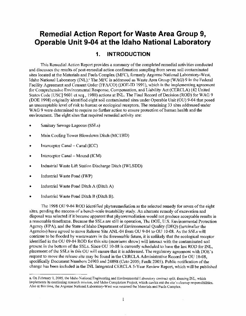
This Remedial Action Report provides a summary of the completed remedial activities conducted and discusses the results of post-remedial action confirmation sampling from seven soil contaminated sites located at the Materials and Fuels Complex (MFC), formerly Argonne National Laboratory-West, Idaho National Laboratory (INL)." The MFC is addressed as Waste Area Group (WAG) 9 in the Federal Facility Agreement and Consent Order (FFNCO) (DOE-ID 199 1), which is the implementing agreement for Comprehensive Environmental Response, Compensation, and Liability Act (CERCLA) (42 United States Code [USC] 9601 et seq., 1980) actions at INL. The Final Record of Decision (ROD) for WAG 9 (DOE 1998) originally identified eight soil contaminated sites under Operable Unit (OU) 9-04 that posed an unacceptable level of risk to human or ecological receptors. The remaining 33 sites addressed under WAG 9 were determined to require no further action to ensure protection of human health and the environment. The eight sites that required remedial activity are:
0 Sanitary Sewage Lagoons (SSLs)
0 Main Cooling Tower Blowdown Ditch (MCTBD)
0 Interceptor Canal - Canal (ICC)
0 Interceptor Canal - Mound (ICM)
0 Industrial Waste Lift Station Discharge Ditch (IWLSDD)
0 Industrial Waste Pond (IWP)
0 Industrial Waste Pond Ditch A (Ditch A)
Industrial Waste Pond Ditch B (Ditch B).
The 1998 OU 9-04 ROD identified phytoremediation as the selected remedy for seven of the eight sites, pending the success of a bench-scale treatability study. An alternate remedy of excavation and disposal was selected if it became apparent that phytoremediation would not produce acceptable results in a reasonable timeframe. Because the SSLs are still in operation, The DOE, U.S. Environmental Protection Agency (EPA), and the State of Idaho Department of Environmental Quality (DEQ) (hereinafter the Agencies) have agreed to move Release Site ANL-04 from OU 9-04 to OU 10-08. As the SSLs will continue to be flooded by wastewaters in the foreseeable future, it is unlikely that the ecological receptor identified in the OU 09-04 ROD for this site (merriams shrew) will interact with the contaminated soil present in the bottom of the SSLs. Since OU 10-08 is currently scheduled to have the last ROD for INL, placement of the SSLs in this OU will ensure that it is addressed. The regulatory agreement with DOE'S request to move the release site may be found in the CERCLA Administrative Record for OU 10-08, specifically Document Numbers 24903 and 24898 (Ceto 2005; Faulk 2005). Public notification of the change has been included in the INL Integrated CERCLA 5-Year Review Report, which will be published
a. On February 1, 2005, the Idaho National Engineering and Environmental Laboratory contract split, forming INL, which implements its continuing research mission, and Idaho Completion Project, which carries out the site's cleanup responsibilities. Also at this time, the Argonne National Laboratory-West was renamed the Materials and Fuels Complex.
1
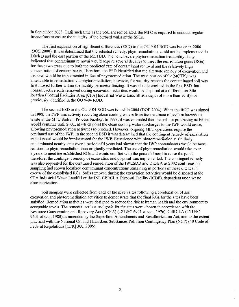
in September 2005. Until such time as the SSL are remediated, the MFC is required to conduct regular inspections to ensure the integrity of the bermed walls of the SSLs.
The first explanation o f significant differences (ESD) to the OU 9-04 ROD was issued in 2000 (DOE 2000). It was determined that the selected remedy, phytoremediation, could not be implemented in Ditch B and the east portion o f the MCTBD. The bench-scale phytoremediation treatability study indicated that contaminant removal would require several decades to meet the remediation goals (RGs) for these two areas due to both the predicted rate of contaminant removal and the relatively high concentration of contaminants. Therefore, the ESD identified that the alternate remedy of excavation and disposal would be implemented in lieu of phytoremediation. The west portion of the MCTBD was amendable to remediation via phytoremediation; however, for security reasons the contaminated soil was first moved further within the facility perimeter fencing. It was also determined in the first ESD that nonradioactive soils removed during excavation activities would be disposed at a different on-Site location (Central Facilities Area [CFA] Industrial Waste Landfill at a depth of more than 10 ft) not previously identified in the OU 9-04 ROD.
The second ESD to the OU 9-04 ROD was issued in 2004 (DOE 2004). When the ROD w-as signed in 1998, the IWP was actively receiving clean cooling waters from the treatment of sodium hazardous waste in the MFC Sodium Process Facility. In 1998, it was estimated that the sodium processing activities would continue until 2002, at which point the clean cooling water discharges to the IWP would cease, allowing phytoremediation activities to proceed. However, ongoing MFC operations require the continued use of the IWP. In the second ESD it was determined that the contingent remedy of excavation and disposal would be implemented for the IWP. Experience with phytoremediation at similarly contaminated nearby sites over a period of 4 years had shown that the IWP contaminants would be more resistant to phytoremediation than originally predicted. The use of phytoremediation would take over 7 years to meet the established RGs and would conflict with the potential need to reuse the pond; therefore, the contingent remedy of excavation and disposal was implemented. The contingent remedy was also requested for the continued remediation of the IWLSDD and Ditch A as 2002 confirmation sampling had shown localized contaminant concentrations remaining in portions of these ditches in excess of the established RGs. Soils removed during the excavation activities would be disposed at the CFA Industrial Waste Landfill or the INL CERCLA Disposal Facility (ICDF), dependent upon waste characterization.
Soil samples were collected from each of the seven sites following a combination of soil excavation and phytoremediation activities to demonstrate that the final RGs for the sites have been satisfied. Remediation activities were designed to reduce the risk to human health and the environment to acceptable levels. The remedial actions and goals for the sites were chosen in accordance with the Resource Conservation and Recovery Act (RCRA) (42 USC 690 1 et seq., 1976), CERCLA (42 USC 9601 et seq., 1980) as amended by the Superfund Amendments and Reauthorization Act, and to the extent practical with the National Oil and Hazardous Substances Pollution Contingency Plan (NCP) (40 Code of Federal Regulations [CFR] 300,2005).
2
2. SITE BACKGROUND: DESCRIPTION AND HISTORY
2.1 Facility History
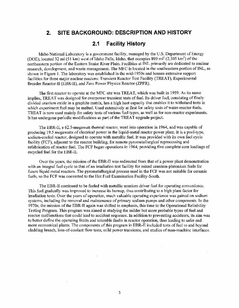
Idaho National Laboratory is a government facility, managed by the U.S. Department of Energy (DOE), located 32 mi (5 1 km) west of Idaho Falls, Idaho, that occupies 890 mi2 (2,305 km2) of the northeastern portion of the Eastern Snake River Plain. Facilities at INL primarily are dedicated to nuclear research, development, and waste management. The MFC is located in the southeastern portion of INL, as shown in Figure 1. The laboratory was established in the mid-1950s and houses extensive support facilities for three major nuclear reactors: Transient Reactor Test Facility (TREAT), Experimental Breeder Reactor-I1 (EBR-11), and Zero Power Physics Reactor (ZPPR).
The first reactor to operate at the MFC site was TREAT, which was built in 1959. As its name implies, TREAT was designed for overpower transient tests of fuel. Its driver fuel, consisting of finely divided uranium oxide in a graphite matrix, has a high heat capacity that enables it to withstand tests in which experiment fuel may be melted. Used extensively at first for safety tests of water-reactor fuels, TREAT is now used mainly for safety tests of various fuel types, as well as for non-reactor experiments. It has undergone periodic modifications as part of the TREAT upgrade project.
The EBR-11, a 62.5-megawatt thermal reactor, went into operation in 1964, and was capable of producing 19.5 megawatts of electrical power in the liquid-metal reactor power plant. It is a pool-type, sodium-cooled reactor, designed to operate with metallic fuel. It was provided with its own fuel cycle facility (FCF), adjacent to the reactor building, for remote pyrometallurgical reprocessing and refabrication of reactor fuel. The FCF began operations in 1964, providing five complete core loadings of recycled fuel for the EBR-11.
Over the years, the mission of the EBR-I1 was redirected from that of a power plant demonstration with an integral fuel cycle to that of an irradiation test facility for mixed uranium-plutonium fuels for future liquid metal reactors. The pyrometallurgical process used in the FCF was not suitable for ceramic fuels, so the FCF was converted to the Hot Fuel Examination Facility-South.
The EBR-I1 continued to be fueled with metallic uranium driver fuel for operating convenience. This fuel gradually was improved to increase its burnup, thus contributing to a high plant factor for irradiation tests. Over the years of operation, much valuable operating experience was gained on sodium systems, including the removal and maintenance of primary sodium pumps and other components. In the 1970s, the mission of the EBR-I1 again was shifted in emphasis, this time to the Operational Reliability Testing Program. This program was aimed at studying the milder but more probable types of fuel and reactor malfunctions that could lead to accident sequence. In addition to preventing accidents, its aim was to better define the operating limits and tolerable faults in reactor operation, thus leading to safer and more economical plants. The components of this program in EBR-I1 included tests of fuel to and beyond cladding breach, loss-of-coolant flow tests, mild power transients, and studies of man-machine interfaces.
3
I
' - -
a-
Figure 1. Location of Idaho National Labomtory and major fmilities.
In the early 198Os, the MFC reexamined the basic design of liquid-md-cooled fast reactors. The results ofthis study led to the Integral Fast Reactor concept, which incqorates four basic elements: sodium cooling; a pool configuration; a c o m p t , intqgd FCF; and a tmwy metal dloy fuel. Modifications to the EBR-II atrd the Hot Fuel Examination Facility-South facilities have been made to support the pmrocessing and €uel manufacturing for the Integral Fast Reactor demonstration project. Since 1994, the MFC has been conducting shutdown and termination activities for the EBR-11. These shutdown activities include defueling and draining the primary and secondary sodium loops, and placing the reactor in a radiologically safe shutdown condition. The FCF has been converted to a fuel conditioning facility. The mission of the fuel conditioning facility is to electrochemically treat EBR-I1 fuel to create radioactive waste forms that are acceptable for disposal in national geologic repositories.
The ZPPR was put into operation in 1969. It was large enough to enable core-physics studies of full-scale breeder reactors that will p d u c e up to 1,000 megawatts. The ZPPR also has been used for mockups of metallic cores and spacareactor cores. This facility was placed in programmatic standby in Fiscal Year 1989.
4
The MFC began a redirected nuclear research and development program in Fiscal Year 1995. The redirect program involves research to help solve near-term, high-priority missions, including the treatment of DOE spent nuclear fuel and reactor decontamination and decommissioning technologies. Within the MFC site are a number of research and support facilities that contribute to the total volume of waste generated at the MFC. These facilities currently generate low-level radioactive waste, radioactive transuranic waste, hazardous waste, mixed waste, sanitary waste, and industrial waste.
2.2 CERCLA Actions at the MFC
In November 1989, EPA placed INL on the National Priorities List of the NCP (40 CFR 300, 2005). The FFNCO (DOE-ID 1991) was developed to establish the procedural framework and schedule for developing, prioritizing, implementing, and monitoring response actions at INL in accordance with CERCLA, RCRA, and the Idaho Hazardous Waste Management Act (HWMA) (State of Idaho 1983). The Agencies determined that hazardous waste release sites at the MFC would be remediated through the CERCLA process, as defined in the FFNCO, which superseded the existing RCRA-driven Consent Order and Compliance Agreement (EPA 1987) requirements.
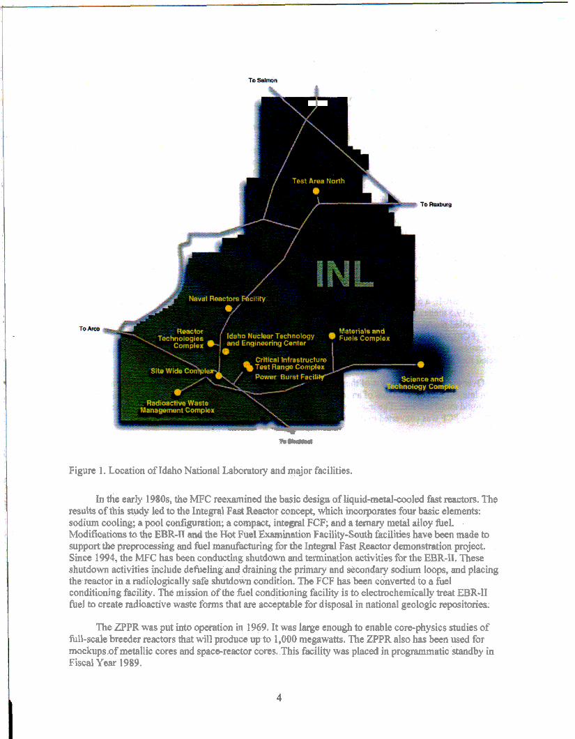
To better manage environmental investigations, INL was divided into 10 WAGS. Identified contaminant release sites in each WAG were divided into OUs to expedite the investigations and any required remedial actions. The WAG 9 covers the MFC and contains four OUs that were investigated for contaminant releases to the environment. The four OUs were classified as: Remedial Investigation Sites, Track 1 Sites, Track 2 Sites, and “No Action” Sites. Idaho National Laboratory released a final ROD for WAG 9 in 1998 (DOE 1998), which identified eight OU 9-04 sites that were determined to pose potential risk to human and/or ecological receptors (see Figure 2). The IWP was still in use at the time the OU 9-04 ROD was issued. It was determined that this site would remain operational until the end of its useful life, at which point remedial activities would commence. The IWP reached the end of its useful life in 2002.
The OU 9-04 ROD selected phytoremediation as the remedy for soil contaminants at the seven MFC WAG 9 OU 9-04 sites with a selected contingent remedy of excavation and disposal of contaminated soils onsite. “Phytoremediation” is the generic term for phytoextraction, an in-situ technology that utilizes plants to extract soil contaminants, removing metals and radionuclides from soils via the normal uptake mechanisms of the plants. The plant vegetation is then harvested, sampled, and disposed in accordance with applicable regulations. This method of remediation was initially chosen since the preliminary characterization sampling indicated that the hazardous and radioactive contaminants of concern (COCs) were predominantly bound in the upper 12 in. of soils, and therefore, would be accessible via plant uptake. Results from a phytoremediation bench scale study conducted in 1998 indicated that these sites could be remediated in approximately 7 years. The final remedy implemented for each of the seven sites addressed to date is shown in Table 1. The following subsections provide a description and history of each of seven sites that underwent remediation activities at the MFC.
5
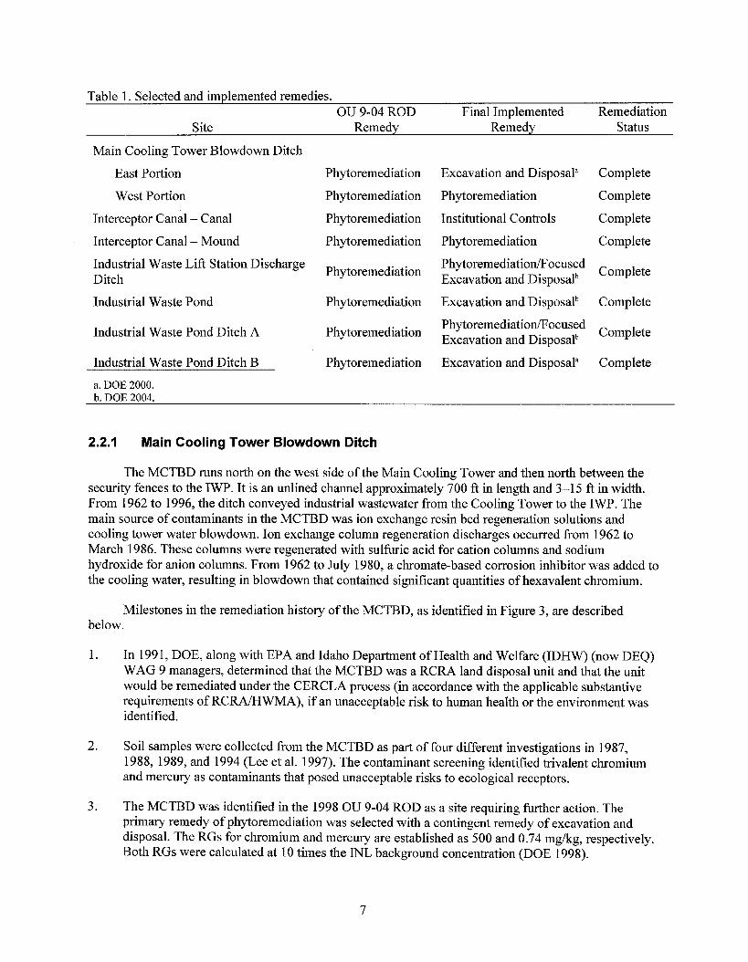
Table 1 . Selected and implemented remedies. OU 9-04 ROD Final Implemented Remediation
Site Remedy Remedy Status
Main Cooling Tower Blowdown Ditch
East Portion
West Portion
Interceptor Canal - Canal
Interceptor Canal - Mound
Industrial Waste Lift Station Discharge Ditch
Industrial Waste Pond
Industrial Waste Pond Ditch A
Industrial Waste Pond Ditch B
a. DOE 2000. h. DOE 2004.
Phytoremediation
Phytoremediation
Phytoremediation
Phytoremediation
Phytoremediation
Phytoremediation
Phytoremediation
Phytoremediation
Excavation and Disposal"
Phytoremediation
Institutional Controls
Phytoremediation
PhytoremediationRocused Excavation and Disposalb
Excavation and Disposalb
PhytoremediatiodFocused Excavation and Disposalb
Excavation and Disposal"
Complete
Complete
Complete
Complete
Complete
Complete
Complete
Complete
2.2.1 Main Cooling Tower Blowdown Ditch
The MCTBD runs north on the west side of the Main Cooling Tower and then north between the security fences to the IWP. It is an unlined channel approximately 700 ft in length and 3-1 5 ft in width. From 1962 to 1996, the ditch conveyed industrial wastewater from the Cooling Tower to the IWP. The main source of contaminants in the MCTBD was ion exchange resin bed regeneration solutions and cooling tower water blowdown. Ion exchange column regeneration discharges occurred from 1962 to March 1986. These columns were regenerated with sulfuric acid for cation columns and sodium hydroxide for anion columns. From 1962 to July 1980, a chromate-based corrosion inhibitor was added to the cooling water, resulting in blowdown that contained significant quantities of hexavalent chromium.
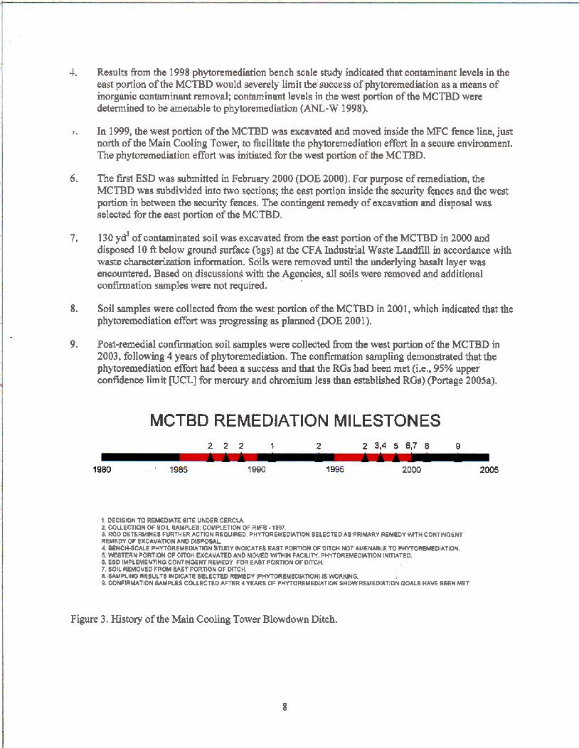
Milestones in the remediation history of the MCTBD, as identified in Figure 3, are described below.
1.
2.
3.
In 1991, DOE, along with EPA and Idaho Department of Health and Welfare (IDHW) (now DEQ) WAG 9 managers, determined that the MCTBD was a RCRA land disposal unit and that the unit would be remediated under the CERCLA process (in accordance with the applicable substantive requirements of R C M W M A ) , if an unacceptable risk to human health or the environment was identified.
Soil samples were collected from the MCTBD as part of four different investigations in 1987, 1988, 1989, and 1994 (Lee et al. 1997). The contaminant screening identified trivalent chromium and mercury as contaminants that posed unacceptable risks to ecological receptors.
The MCTBD was identified in the 1998 OU 9-04 ROD as a site requiring further action. The primary remedy of phytoremediation was selected with a contingent remedy of excavation and disposal. The RGs for chromium and mercury are established as 500 and 0.74 mg/kg, respectively. Both RGs were calculated at 10 times the INL background concentration (DOE 1998).
7
4.
I .
6.
7.
8.
9.
Results from the 1998 phytoremediation bench scale study indicated that contaminant levels in the east portion of the MCTBD would severely limit the success of phytoremediation as a means of inorganic contaminant removal; contaminant levels in the west portion of the MCTBD were determined to be amenable to phytoremediation (ANL-W 1998).
In 1999, the west portion of the MCTBD was excavated and moved inside the MFC fence line, just north of the Main Cooling Tower, to facilitate the phytoremediation effort in a secure environment. The phytoremediation effort was initiated for the west portion of the MCTBD.
The first ESD was submitted in Februmy 2000 (DOE 2000). For purpose of remediation, the MCTBD was subdivided into two sections; the east portion inside the security fences and the west portion in between the security fences. The contingent remedy of excavation and disposal was selwted for the east portion of the MCTBD,
130 y d of contaminated soil was excavated from the east portion of the MCTBD in 2000 and disposed 10 ft below ground surface (bgs) at the CFA Industrial Waste Landfill in accordance with waste charttcterization information. Soils were removed until the underlying basalt layer was encountered. B a d on discussions with the Agencies, all soib were removed and additional confirmation samples were not required.
Soil samples were collected from the west portion of the MCTBD in 200 1, which indicated that the phytoremediation effort was progressing as planned (DOE 2001).
Post-remedial confirmation soil samples were collected from the west portion of the MCTBD in 2003, following 4 years of phytoremediation. The confirmation sampling demonstrated that the phytoremediation effort had been a success and that the RGs had been met (ie., 95% upper confidence limit WCL] for mercury md chromium less than established RGs) (Portage 2005a).
MCTBD REMEDIATION MILESTONES 2 2 2 1 2 2 3,4 5 6 7 8 9
1980 , l! IW 19 2000 2 m
1 DECISION TO REMEDJATE SITE UNDER CERCU. 2 COUECTIOH of SOIL SAMPLES, COMPLETION OF RWS - 1 W7. a ROD DETERMINES FURTHER ACTION REQUIRED. PHYTOREMEDLATIOH SELECTED AS PRIMARY REMEDY W H CONTINGENT REMEDY OF EXCAVATION AND DEPOSAL.
5 MSTERN PORTION OF DITCH EXCAVATED AND MOMD W H I N FAClLITT. PHYTM(EME0IATK)N INITIATED 1. ESP IMPLEMENTING CONTINGENT REMEDY FOR EAST PORTION OF DiTCH. 7, SOIL REMOVED FROM MAST PORTlOH OF DITCH 8 SAMPLINO RESULTS INDICATE SELECTED REMEDY (PHYTOREMEDWTWH) IS WORKING. 9, CONFIRMATION SAMPLES COUECRD AFTER 4YEARS OF PHYTOREMEDIATION SHOWREMEDLlYQN GOALS HAVE BEEN MET
4. BEWCH-SCALE PWOREMEDIATKIN BTUOY INOICATES EAST PORTION OF DITCH NOT AMENABLE TO PHYTOREMEDIATIOH,
Figure 3. History of the Main Cooling Tower Blowdown Ditch.
8
2.2.2 Interceptor Canal - Canal and Interceptor Canal - Mound
The ICC transported industrial waste water to the IWP and diverted spring runoff and other natural waters around the MFC facility to the IWP. Between 1962 and 1975, two 4-in. pipes transported industrial waste water and cooling tower effluent to the ICC. One line transported cooling tower blowdown water and ion exchange column regeneration effluent while the other line originated at the Industrial Waste Lift Station and transported industrial waste water. Liquid radioactive waste was discharged through the same line as the industrial waste water, but it was diverted to the EBR-I1 Leach Pit. The ICM was formed when 1,384 m3 (1,810 yd3) of dredged material was placed on the bank of the ICC.
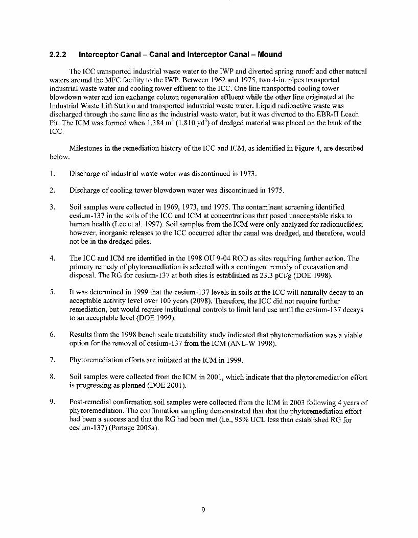
Milestones in the remediation history of the ICC and ICM, as identified in Figure 4, are described below.
1.
2.
3.
4.
5.
6.
7.
8.
9.
Discharge of industrial waste water was discontinued in 1973.
Discharge of cooling tower blowdown water was discontinued in 1975.
Soil samples were collected in 1969, 1973, and 1975. The contaminant screening identified cesium- 137 in the soils of the ICC and ICM at concentrations that posed unacceptable risks to human health (Lee et al. 1997). Soil samples from the ICM were only analyzed for radionuclides; however, inorganic releases to the ICC occurred after the canal was dredged, and therefore, would not be in the dredged piles.
The ICC and ICM are identified in the 1998 OU 9-04 ROD as sites requiring further action. The primary remedy of phytoremediation is selected with a contingent remedy of excavation and disposal. The RG for cesium-137 at both sites is established as 23.3 pCi/g (DOE 1998).
It was determined in 1999 that the cesium-137 levels in soils at the ICC will naturally decay to an acceptable activity level over 100 years (2098). Therefore, the ICC did not require further remediation, but would require institutional controls to limit land use until the cesium- 137 decays to an acceptable level (DOE 1999).
Results from the 1998 bench scale treatability study indicated that phytoremediation was a viable option for the removal of cesium-137 from the ICM (ANL-W 1998).
Phytoremediation efforts are initiated at the ICM in 1999.
Soil samples were collected from the ICM in 2001, which indicate that the phytoremediation effort is progressing as planned (DOE 2001).
Post-remedial confirmation soil samples were collected from the ICM in 2003 following 4 years of phytoremediation. The confirmation sampling demonstrated that that the phytoremediation effort had been a success and that the RG had been met (Le., 95% UCL less than established RG for cesium-137) (Portage 2005a).
9
ICC AND ICM REMEDIATION MILESTONES 3 1,3 2,3 3 4,85,7 8 9
. . .. . . . . .
I S T O 1975 1980 I985 1990 1995 2000 2005
1. DISCHARGE OF INDUSTRIAL WASTEWAER DISCOMIWED 2 D I S C M G E OF CWLIMQ WATER 6Lol rvDW PISCOHTIHUED.
4. ROD OETERMINES FURTHER ACTION REQUIRED. PHYTOKMEDIATION SELECTED AS PRMARY REMEDY W" CONTINGENT W E D Y OF EXCAVARON AND DIII-. 6. DETERMINED THAT CS-I 37 WLL NATURALLY DECAY W H I N 100YR INSflTUTlOHAL CONTROLS APPLIED TO ICC 6. BENCH-SCALE PHYrOREMEDUTlON STUDY COMPLETE. 7. PHYTOREMEDIATION INITIATED ICM 8. SAMPLlHO RESULTS INOlCATE SELECTED REMEDY (PHYTOREMEDIATION) IS WORKING. g. CONFIRMATIOM SAMPLES COLLECTED AFTER QYEARS OF P!-tYrOEMEDIATION SHOW REMEMATlON OWLS HAVE BEEN MET.
5. COLECTION OF SOIL SMPLES (lw I@7b AND 1075); C M P l H H OT R F S - 1987.
Figure 4. History of the Interceptor Canal - Canal and Interceptor Canal - Mound.
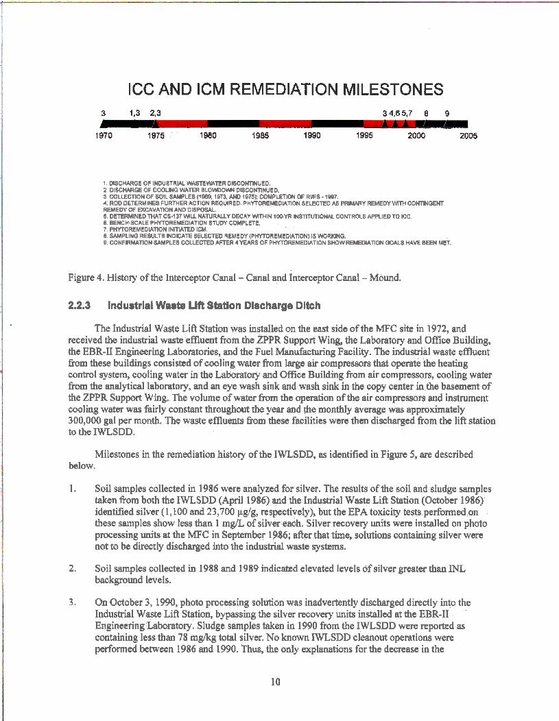
2.2.3 lndustrlal Waate Lift Station Discharge Ditch
The Industrial Waste Lift Station was installed on the east side of the MFC site in 1972, md received the industrid waste effluent from the ZPPR Support Wing, the Labomtory and Oflice Building, the EBR-II Engineering Laboratories, and the Fuel Manufacturing Facility. The industrial waste effluent from these buildings consisted of cooling water from large air compressors that operate the heating control system, cooling water in the Laboratory and Office Building from air compressorsy cooling water from the analytical laboratory, and an eye wash sink and wash sink in the copy center in the basement of the ZPPR Support Wing. The volume of water from the operation of the air compressors and instrument cooling water was fairly constant throughout the year and the monthly average was approximately 300,000 gal per month. The waste emuents from these facilities were then discharged from the lift station to the IWLSDD.
Milestones in the remediation history of the IWSDD, as identified in Figure 5, are described below.
1. Soil samples collected in 1986 were analyzed for silver. The results of the soil and sludge samples &en from both the IWLSDD (April 1986) and the Industrial Waste Lift Station (October 1986) identified silver { 1,100 and 23,700 pg/g, respectively), but the EPA toxicity tests performed on these samples show less than 1 mg/L of silver each. Silver recovery units were installed on photo processing units at the MFC in September 1986; after that t h e , solutions containing silver were not to be directly discharged into the industrial waste systems.
2. Soil samples collected in 1988 and 1989 indicated elevated levels of silver greater than INL background levels.
3. On October 3, 1990, photo processing solution was inadvertently discharged directly into the Industrial Waste LiR Station, bypassing the silver recovery units installed at the EBR-I1 Engineeting Laboratory. Sludge samples taken in 1990 from the IWLSDD were reported as containing less than 78 mglkg total silver. No known M S D D cleanout operations were performed between 1986 and 1990. Thus, the only explanations for the decrease in the
10
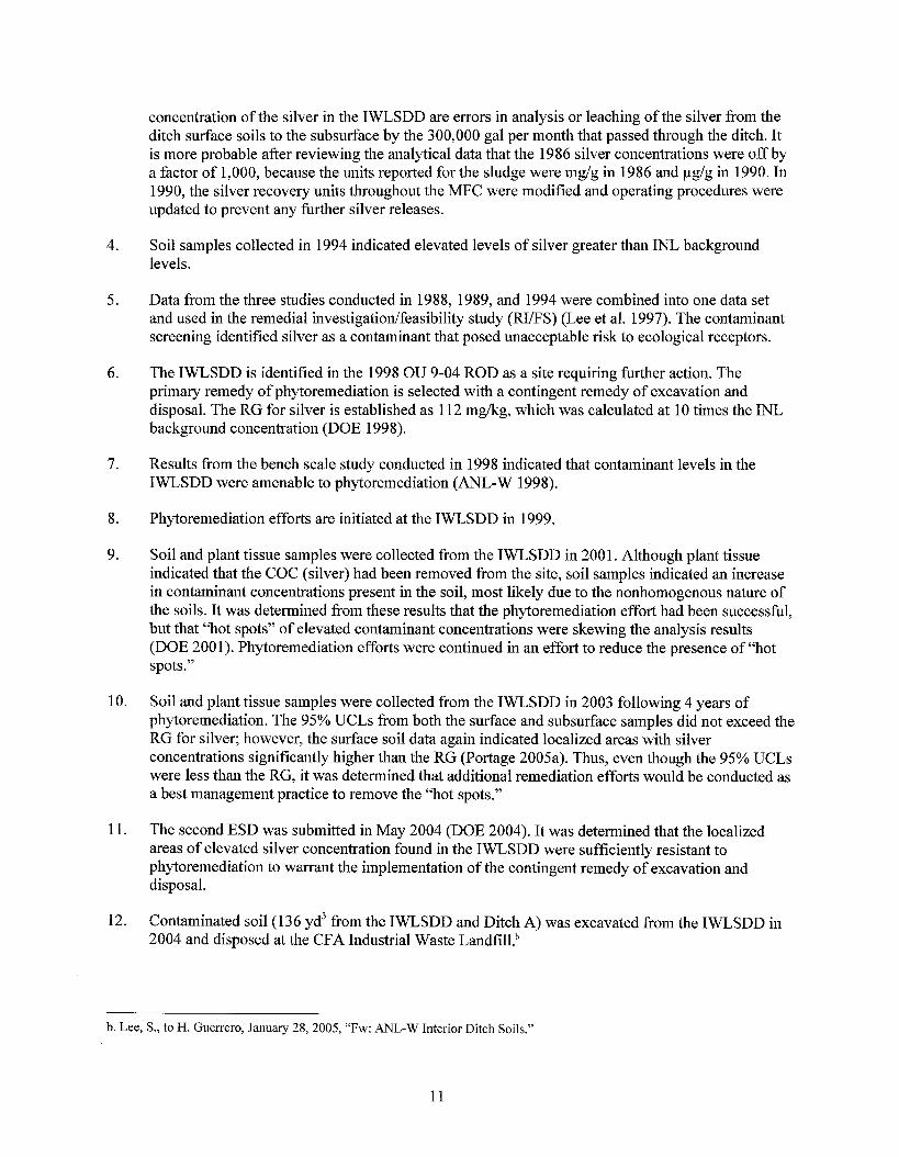
4.
5.
6.
7.
8.
9.
10.
11.
12.
concentration of the silver in the IWLSDD are errors in analysis or leaching of the silver from the ditch surface soils to the subsurface by the 300,000 gal per month that passed through the ditch. It is more probable after reviewing the analytical data that the 1986 silver concentrations were off by a factor of 1,000, because the units reported for the sludge were mg/g in 1986 and pg/g in 1990. In 1990, the silver recovery units throughout the MFC were modified and operating procedures were updated to prevent any further silver releases.
Soil samples collected in 1994 indicated elevated levels of silver greater than INL background levels.
Data from the three studies conducted in 1988, 1989, and 1994 were combined into one data set and used in the remedial investigatiordfeasibility study (RI/FS) (Lee et al. 1997). The contaminant screening identified silver as a contaminant that posed unacceptable risk to ecological receptors.
The IWLSDD is identified in the 1998 OU 9-04 ROD as a site requiring further action. The primary remedy of phytoremediation is selected with a contingent remedy of excavation and disposal. The RG for silver is established as 112 mgkg, which was calculated at 10 times the INL background concentration (DOE 1998).
Results from the bench scale study conducted in 1998 indicated that contaminant levels in the IWLSDD were amenable to phytoremediation (ANL-W 1998).
Phytoremediation efforts are initiated at the IWLSDD in 1999.
Soil and plant tissue samples were collected from the IWLSDD in 2001. Although plant tissue indicated that the COC (silver) had been removed from the site, soil samples indicated an increase in contaminant concentrations present in the soil, most likely due to the nonhomogenous nature of the soils. It was determined from these results that the phytoremediation effort had been successful, but that “hot spots” of elevated contaminant concentrations were skewing the analysis results (DOE 200 1). Phytoremediation efforts were continued in an effort to reduce the presence of “hot spots.”
Soil and plant tissue samples were collected from the IWLSDD in 2003 following 4 years of phytoremediation. The 95% UCLs from both the surface and subsurface samples did not exceed the RG for silver; however, the surface soil data again indicated localized areas with silver concentrations significantly higher than the RG (Portage 2005a). Thus, even though the 95% UCLs were less than the RG, it was determined that additional remediation efforts would be conducted as a best management practice to remove the “hot spots.”
The second ESD was submitted in May 2004 (DOE 2004). It was determined that the localized areas of elevated silver concentration found in the IWLSDD were sufficiently resistant to phytoremediation to warrant the implementation of the contingent remedy of excavation and disposal.
Contaminated soil (1 3 6 yd3 from the IWLSDD and Ditch A) was excavated from the IWLSDD in 2004 and disposed at the CFA Industrial Waste Landfill.b
b. Lee, S., to H. Guerrero, January 28,2005, “Fw: ANL-W Interior Ditch Soils.”
11
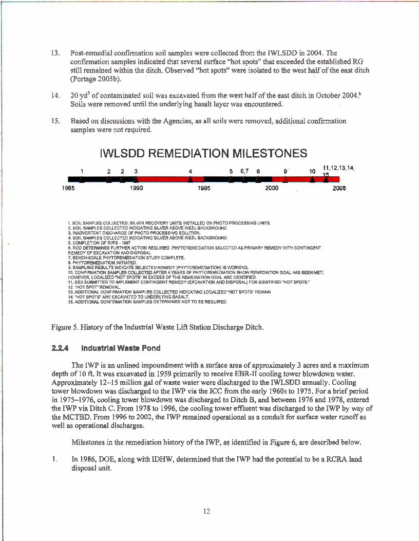
13.
14.
15.
Post-remedial confirmation soil samples were collected from the IWLSDD in 2004. The confirmation samples indicated that several surface "hot spots" that exceeded the established RG still remained within the ditch. Observed "hot spots" were isolated to the west half of the east ditch (Portage 2005b).
20 yd3 of contaminated soil was excavated from the west half of the east ditch in October 2004: Soils were removed until the underlying basalt layer was encountered.
Based on discussions with the Agencies, as all soils were removed, additional confirmation samples were not required.
IWLSDD REMEDIATION MILESTONES 11,12,13314,
1 2 2 3 4 5 6,7 0 9 10 4c
1985 I990 1995 2000 2005
1. Sol1 SAMPLES CMLECTED SILVER RECOVERY UNITS INSTALLED ON PHOTO PROCESSINQ UNm. 2.80tL WMPLES COLLECTED INDICATING SILVER M O M INEEL RACKQROUND. 3. INADVERTENT D I S C M G E OF PHOTO PROCWS+MG SOLUTION. 4. SOlL 8pMPE8 COLLECTED INDICATHG SILVER ABM INEEL BACKGROUND.
6. ROD DETERMINE8 FURTHER ACTION REQUIRE0 P!-iTOREMEOLATION SELECTED A8 PRIMARY REMEDY Wrm MMINGENT REMEDY OF EXCAVATDN AND DISPOSAL 7. BENCWCALE PHYlOFlEMEOlATKIN STUDY COMpCElE. 8. PHYTOREMEDLA~ HITlATED. @. W W N G RESULT5 INDIGAT€ SEEC'ED REMEDY (PHTTOREMEDUTDN) IS WKING. 10. CONFIRMAWN BA)rspLE8 CQUEGTED AFTER 4 YEARS OF FHYTOREMEDIAM SHOW REYEDHTOOH GOAL Hcw BEEN MET; HOMVER. LOCALIZED "HOT SPOT@' IN EXCESS OF THE REMEDlAROH QOAL ARE IDENnFlEO 1 I. ESD S#MllTED TO IMPLEMENT CONTINGENT REMEDY (EXGAVAlWN AND OlSPosAL) FOR YlEHTlFlED 'HOT BWTS." 12 "WT SPOT" REMOVAL.
14. "WT SPOTS' ARE EKMVATED TO UNDERLYING OMAT. 16. AWI~IONAL COHFIRh44TKW SAMPLES DETERMINED NOT TO BE REaUIRED.
5. COMPLETION OF RVFS - lW7
la ~ O M U CONFIMWPI WPES COLLECTED IHDIWTMG LOCMED "HCITSPOW REMW
Figure 5. History of the Industrial Waste Lifk Station Discharge Ditch.
2.2.4 lndustrlal Wa8te Pond
The IWP is an unlined impoundment with a surface area of approximately 3 acres and a maximum depth of 10 ft. It was excavated in 1959 primarily to receive EBR-I1 cooling tower blowdown water. Approximately 12-1 5 million gal of waste water were discharged to the IWLSDD annually. Cooling tower blowdown was discharged to the IWP via the ICC from the early 1960s to 1975. For a brief period in 1975-1976, cooling tower biowdown was discharged to Ditch B, md between 1976 and 1978, entered the IWP via Ditch C. From 1978 to 1996, the cooling tower effluent was discharged to the IWP by way of the MCTBD. From 1996 to 2002, the IWP remained operational as a conduit for surface water runoff as well as operational discharges.
Milestones in the remediation history of the IW, as identified in Figure 6, are described below.
1. In 1986, DOE, dong with IDHW, determined that the IWP had the potential to be a RCRA land disposal unit.
12
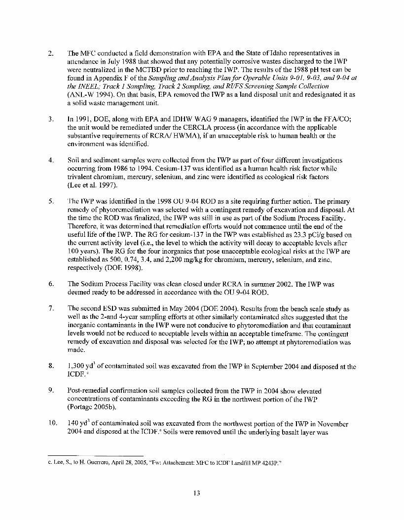
2.
3.
4.
5 .
6.
7.
8.
9.
10.
The MFC conducted a field demonstration with EPA and the State of Idaho representatives in attendance in July 1988 that showed that any potentially corrosive wastes discharged to the IWP were neutralized in the MCTBD prior to reaching the IWP. The results of the 1988 pH test can be found in Appendix F of the Sampling andAnalysis Plan for Operable Units 9-01, 9-03, and 9-04 at the INEEL; Track I Sampling, Track 2 Sampling, and H/FS Screening Sample Collection (ANL-W 1994). On that basis, EPA removed the IWP as a land disposal unit and redesignated it as a solid waste management unit.
In 1991, DOE, along with EPA and IDHW WAG 9 managers, identified the IWP in the FFNCO; the unit would be remediated under the CERCLA process (in accordance with the applicable substantive requirements of RCRA/ HWMA), if an unacceptable risk to human health or the environment was identified.
Soil and sediment samples were collected from the IWP as part of four different investigations occurring from 1986 to 1994. Cesium- 137 was identified as a human health risk factor while trivalent chromium, mercury, selenium, and zinc were identified as ecological risk factors (Lee et al. 1997).
The IWP was identified in the 1998 OU 9-04 ROD as a site requiring further action. The primary remedy of phytoremediation was selected with a contingent remedy of excavation and disposal. At the time the ROD was finalized, the IWP was still in use as part of the Sodium Process Facility. Therefore, it was determined that remediation efforts would not commence until the end of the useful life of the IWP. The RG for cesium-137 in the IWP was established as 23.3 pCi/g based on the current activity level (i.e., the level to which the activity will decay to acceptable levels after 100 years). The RG for the four inorganics that pose unacceptable ecological risks at the IWP are established as 500, 0.74,3.4, and 2,200 mgkg for chromium, mercury, selenium, and zinc, respectively (DOE 1998).
The Sodium Process Facility was clean closed under RCRA in summer 2002. The IWP was deemed ready to be addressed in accordance with the OU 9-04 ROD.
The second ESD was submitted in May 2004 (DOE 2004). Results from the bench scale study as well as the 2-and 4-year sampling efforts at other similarly contaminated sites suggested that the inorganic contaminants in the IWP were not conducive to phytoremediation and that contaminant levels would not be reduced to acceptable levels within an acceptable timefi-ame. The contingent remedy of excavation and disposal was selected for the IWP; no attempt at phytoremediation was made.
1,300 yd3 of contaminated soil was excavated from the IWP in September 2004 and disposed at the ICDF.
Post-remedial confmation soil samples collected from the IWP in 2004 show elevated concentrations of contaminants exceeding the RG in the northwest portion of the IWP (Portage 2005b).
140 yd3 of contaminated soil was excavated from the northwest portion of the IWP in November 2004 and disposed at the ICDF." Soils were removed until the underlying basalt layer was
c. Lee, S., to H. Guerrero, April 28,2005, "Fw: Attachement: MFC to ICDF Landfill MP 4243P."
13
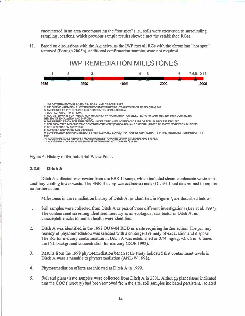
encountered in an m a encompassing the “hot spot” &e., soils were excavated to surrounding sampling locations, which previous sample results showed met the established RGs).
1 1. Based on discussions with the Agencies, as the IWP met all RGs with the chromium “hot spot’’ removed (Portage 2005b), additional confirmation samples were not required.
IWP REMEDIATION MILESTONES 1 2 3 4 5 6 7,8,9,10,11
1985 1990 1995 2MH) 2005
1. IW DETERMINED TO BE POTENTIAL RCRA IAN0 DISPOSAL UNIT. 2. FIEU) DEMONSTPATION SHOlMNQ CORROSIVE WASTE8 H E W E D PRIORTO REACHING W 3. I W IOEMIFIED IN THE F F W O FOR REMEOWTON UNDER CERCIA
5. ROD DETERMINES FURMER ACTlOH REQUIRED. PHYTOREMEDIATION BECECTED A8 PRlMARY REMEDY WTH CONTINGENT REMEDY OF EXCAVATION AND DISPOSA 6. I W DEEMED M Y FOR RHEDURDN UNWR CERCIA FOUOWNO CLOSURE OF SODIUM PROCE88 FACILrTy. 7. ESD SUBbrllfTED IMPLEMENTING CONTiNGENT REMEDY (EXCAVATION AND DISPOSAL) BASED ON K N W O E FROM ONGOINQ P H Y T ~ E D I A f l O N A C M E S .
A COMPLETIOH Of RllFl - IW.
8. IW SOIL8 U(CAVATE0 AHD DISPWD. B, CONFIRMATION SAMPLING REIULTI S K I W W A T E D COHCENTRATIOHS OF CONTAMlNAlYrS IN lHC NORlHWST CORNER OFTME w. IO. ADDITIONAL SOILS REMOVED FROM NORE-IWSTCORNER OF IW TO UNMRLYIHO BASALT. 11. ADDTTIOMAL C O N F I M m W P E S DETERMINED NOT TO 8 E REQUIRED.
Figure 6. History of the Industrial Waste Pond.
2.2.5 DitchA
Ditch A collected wastewater from the EBR-I1 sump, which included steam condensate w s t e and auxiliary cooling tower waste. The EBR-I1 sump was addressed under OU 9-01 and determined to require no further action.
1.
2.
3.
4.
5 .
Milestones in the remediation history of Ditch A, as identified in Figure 7, are described below.
Soil samples were collected from Ditch A as part of three different investigations me et al. 1997). The contaminant screening identified mercury as an ecological risk factor in Ditch A; no unacceptable risks to human health were identified.
Ditch A was identified h the 1998 OU 9-04 ROD as a site requiring further action. The primary remedy of phytoremediation was selected with a contingent remedy of excavation and disposal. The RG for mercury contamination in Ditch A was established IS 0.74 mgkg, which is 10 times the background concentration for mercury (DOE 1998).
Results from the 1998 phytoremediation bench scale study indicated that contaminant levels in Ditch A were amenable to phytoremediation (ANL-W 1998).
Phytoremediation efforts are initiated at Ditch A in 1999.
Soil and plant tissue samples were collected from Ditch A in 200 1, Although plant tissue indicated that the COC (mercury) had been removed from the site, soil samples indicated persistent, isolated
14
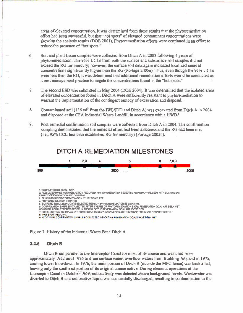
areas of elevated concentration. It was determined fiom these results that the phytoremediation effort had been successful, but that “hot spots” of elevated contaminant concentrations were skewing the analysis results (DOE 2001). Phytoremediation efforts were continued in an effort to reduce the presence of “hot spots.”
6. Soil and plant tissue samples were collected from Ditch A in 2003 following 4 years of phytmrnediation. The 95% UCLs from both the surface and subsdace soil samples did not exceed the RG for mercury; however, the surface soil data again indicated Iodized mas at concentrations significantly higher than the RG (Portage 2005a). Thus, even though the 95% UCLs were less than the RG, it was determind that additional remediation efforts would be conducted as a best management practice to negate the concentrations found in the “hot spots.”
7. The second ESD was submitted in May 2004 (DOE 2004). It was determined that the isolated areas of elevated concentration found in Ditch A were sufficiently resistant to phytoremediation to w m t the implementation of the contingent remedy of excavation and disposal.
Contaminated soil (136 yd3 h m the IWLSDD and Ditch A) was excavated from Ditch A in 2004 and disposed at the CFA Industrial Waste Landfill in accordance with a HWD?
8.
9. Post-remedial confirmation soil samples were collected from Ditch A in 2004. The confirmation sampling demonstrated that the remedial effort had been a success and the RG had been met (i.e., 95% UCL less than established RG for mercury) (Portage 2005b).
DITCH A REMEDIATION MILESTONES 1 4 5 6 7,8,9
I995 2000 2005
1. COMPLETION OF RlFS - 1BB7. 2. ROD DETERMINES FURTHER ACTION REaulRfD ~ E M E M A n O H SELECTED M PWARY REMEDY \MTH CONTlNQENl REMEW Cf M-VATION AND M W W .
4 W O R U I E D I A T I O N INITIATED. 5, WPLINO RE8ULTS INDlCAfE S€ECT€O REMEOY (PhTOREMMEMATION) IS W W N Q .
HOWEVER, W E E D 7. ESO SUBlullTfED TO IMPLEMENT C M l WENT REYEW IUtUVATION AND MSWSALl FOR IOEhTIFIED “HM SPWS
a. BENCHWLE WDREMEMATION STUDY COMPLETE
6 CONFIRMATWN SAMPLE8 COLLECTED AFlER 4 Y U R S OF PHWOREYEMATION SHOW REMEDIATION W A L HAS BEEN MET; Spofs” 1H EX- OF THE REMEMATION GOAL ARE IDENTIFIER
Figure 7. History of the Industrial Waste Pond Ditch A.
2.2.6 Dltch 8
Ditch B ran parallel to the Interceptor Cand for most of its course md was used from approximately 1962 until 1976 to drain surface water, overflow waters from Building 760, and in 1975, cooling tower blowdown. In 1976, the main portion of Ditch B (outside the MFC fence) was backfilled, leaving only the southeast portion of its original course active. During cleanout operations at the Interceptor Canal in October 1969, radioactivity was detected above background levels. Wastewater was diverted to Ditch B and radioactive liquid was accidentally discharged, resulting in contamination to the
15
surface soils of the ditch. The radioactive effluent originated in the retention tank at the Laboratory and Offices Building and should have been ckwted to the EBR-I1 Leach Pit. The area was surveyed and the contaminated soil was removed.
Milestones in the remediation history of Ditch B, as identified in Figure 8, are described below:
1.
2.
3.
4.
J .
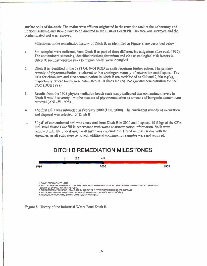
Soil samples were collected from Ditch B as p~ of t h e e different investigations (Lee et al. 1997). The contaminant screening identified trivalent chromium and zinc as ecological risk factors in Ditch B; no unacceptable risks to human health were identified.
Ditch B is identifEd in the 1998 OU 9-04 ROD as a site requiring further action. The primary remedy of phytoremediation is selected with a contingent remedy of excavation and disposal. The RGs for chromium and zinc contamination in Ditch B are established as 500 and 2,200 mgkg, respectively. These levels were calculated at 10 times the INL background concentration for each COC (DOE 1998).
Results from the 1998 phytoremediation bench scale study indicated that contaminant levels in Ditch B would severely limit the success of phytoremediation as a means of inorganic contaminant removal (ANL-W 1998).
The frst ESD was submitted in February 2000 {DOE 2000). The contingent remedy of excavation and disposal was selected for Ditch 3,
30 yd3 of contaminated soil was excavated fiom Ditch B in 2000 and disposed 10 ft bgs at the CFA Industrial Waste Landfill in accordance with waste characterization information. Soils were removed until the underlying basalt layer was encountered. Based on discussions with the Agencies, as all soils were removed, additional confirmation samples were not required.
DITCH B REMEDIATIUN MILESTONES 1 2.3 4,5
1995
1 COMPLETION OF RIFS - 1W7. 2 Fwo MfERMlNES FURTHER ACTION REQUIRED. PHYTOREMEDLA'TION SELECTED AS PRfMARY REMEDY WTH CONTINGENT REMEDY DF EXCAVATlON AND oISF#AL 3 PlMOREMEMATlON BENCH -LE STUDY IMICATES PWOREMEDIATION NOT APPROPRfATTE. 4 ESD SUBlulllTED IMPLEMENtlND CONTINOEM REMEDY (EXCAVATION AND MSW3L1. 5. REMOVAL ff WKlAMlNATED SOIL TO U N E R L Y M BASALT.
Figure 8. History of the Industrial Waste Pond Ditch B.
16