REMEDIAL ACTION PLAN _RAP_FSR/Former Kas… · Remedial Action Plan Former Kast Property iii...
106
Remedial Action Plan Former Kast Property i REMEDIAL ACTION PLAN REMEDIAL ACTION PLAN FORMER KAST PROPERTY CARSON, CALIFORNIA Prepared for Shell Oil Products US 20945 S. Wilmington Avenue Carson, California 90810 March 10, 2014 Prepared by URS Corporation 2020 East First Street, Suite 400 Santa Ana, CA 92705 (714) 835-6886 Fax: (714) 433-7701 and Geosyntec Consultants 924 Anacapa Street, Suite 4A Santa Barbara, California 93101
Transcript of REMEDIAL ACTION PLAN _RAP_FSR/Former Kas… · Remedial Action Plan Former Kast Property iii...
Remedial Action Plan Former Kast Property
i
R E M E D I A L A C T I O N P L A N
REMEDIAL ACTION PLAN
FORMER KAST PROPERTY CARSON, CALIFORNIA
Prepared for
Shell Oil Products US 20945 S. Wilmington Avenue Carson, California 90810
March 10, 2014
Prepared by
URS Corporation 2020 East First Street, Suite 400 Santa Ana, CA 92705 (714) 835-6886 Fax: (714) 433-7701 and
Geosyntec Consultants 924 Anacapa Street, Suite 4A Santa Barbara, California 93101

Remedial Action Plan Former Kast Property
iii
CERTIFICATION
REMEDIAL ACTION PLAN
FORMER KAST PROPERTY CARSON, CALIFORNIA
I am the Senior Project Manager for Equilon Enterprises LLC, doing business as Shell Oil Products US, for this project. I am informed and believe that the matters stated in the this Remedial Action Plan for the former Kast Property, Carson, California are true, and on that ground I declare, under penalty of perjury in accordance with Water Code section 13267, that the statements contained therein are true and correct.
Douglas Weimer Sr. Principle Program Manager Shell Oil Products US March 10, 2014

Remedial Action Plan Former Kast Property
iv
TABLE OF CONTENTS
Section Page
EXECUTIVE SUMMARY ......................................................................................................................... ES-1
1.0 INTRODUCTION ........................................................................................................................... 1-1
1.1 REGULATORY BASIS ............................................................................................. 1-1
1.2 OBJECTIVES .......................................................................................................... 1-2
1.3 PUBLIC REVIEW PROCESS ..................................................................................... 1-3
1.4 ORGANIZATION OF THE RAP ................................................................................ 1-4
2.0 SITE BACKGROUND ................................................................................................................... 2-1
2.1 SITE HISTORY ....................................................................................................... 2-1
2.2 REGULATORY INVOLVEMENT ............................................................................... 2-2
2.3 SUMMARY OF SITE CONDITIONS AND STATEMENT OF THE ISSUE .......................... 2-2
2.4 SITE SETTING, GEOLOGY AND HYDROGEOLOGY ................................................... 2-3
2.5 BACKGROUND INFORMATION ON SURROUNDING PROPERTIES .............................. 2-4
Former Turco Products/Purex Facility ..................................................... 2-4 2.5.1 Former Fletcher Oil and Refining Company ........................................... 2-5 2.5.2 Oil Transport Company Inc. .................................................................... 2-5 2.5.3 Oil Wells .................................................................................................. 2-6 2.5.4 Dry Cleaners ............................................................................................ 2-6 2.5.5 Pipelines ................................................................................................... 2-6 2.5.6
3.0 PREVIOUS INVESTIGATIONS .................................................................................................... 3--1
3.1 ASSESSMENTS IN NON-RESIDENTIAL AREAS, PUBLIC STREETS, AND
RAILROAD RIGHT-OF-WAY................................................................................... 3-1
3.2 ASSESSMENT AT INDIVIDUAL RESIDENTIAL PROPERTIES ...................................... 3-2
Methane Screening ................................................................................... 3-3 3.2.1 Soil Sampling ........................................................................................... 3-3 3.2.2 Sub-Slab Soil Vapor Sampling ................................................................ 3-3 3.2.3 Indoor Air Sampling ................................................................................ 3-4 3.2.4 Human Health Screening Risk Evaluation (HHSRE) .............................. 3-4 3.2.5
3.3 FINDINGS OF ASSESSMENT WORK ......................................................................... 3-5
Impacts in Soil ......................................................................................... 3-6 3.3.1 Impacts in Soil Vapor .............................................................................. 3-7 3.3.2 Impacts in Indoor and Outdoor Air .......................................................... 3-8 3.3.3 Impacts in Groundwater ........................................................................... 3-8 3.3.4
3.4 RESIDUAL CONCRETE RESERVOIR SLAB ASSESSMENT ....................................... 3-11
4.0 SUMMARY OF INTERIM ACTIONS COMPLETED AND PILOT TESTING ................................. 4-1
4.1 EVALUATIONS OF NEED FOR INTERIM ACTIONS .................................................... 4-1
Summary of Interim Actions Completed ................................................. 4-1 4.1.14.2 SUPPORT TO UTILITY EXCAVATIONS AND HOMEOWNERS’ ACTIVITIES ................. 4-2

Remedial Action Plan Former Kast Property
v
4.3 SUMMARY OF PILOT TESTING ............................................................................... 4-2
SVE Pilot Testing .................................................................................... 4-3 4.3.1 Bioventing Pilot Testing .......................................................................... 4-3 4.3.2 Excavation Pilot Testing .......................................................................... 4-3 4.3.3 In-Situ Chemical Oxidation (ISCO) Pilot Testing ................................... 4-5 4.3.4
5.0 REMEDIAL ACTION OBJECTIVES AND SITE-SPECIFIC CLEANUP GOALS .......................... 5-1
5.1 REMEDIAL ACTION OBJECTIVES ........................................................................... 5-1
5.2 SITE-SPECIFIC CLEANUP GOALS ........................................................................... 5-2
Soil ........................................................................................................... 5-2 5.2.1 SSCGs for Soil Vapor .............................................................................. 5-3 5.2.2 SSCGs for Groundwater .......................................................................... 5-4 5.2.3
6.0 SUMMARY OF HUMAN HEALTH RISK ASSESSMENT ............................................................. 6-1
6.1 HHRA OVERVIEW ................................................................................................ 6-1
6.2 POTENTIAL RESIDENTIAL EXPOSURES .................................................................. 6-2
6.3 POTENTIAL CONSTRUCTION AND UTILITY MAINTENANCE WORKER
EXPOSURES ........................................................................................................... 6-4
6.4 POTENTIAL SOIL LEACHING TO GROUNDWATER ................................................... 6-4
6.5 HHRA SUMMARY ................................................................................................. 6-4
7.0 SUMMARY OF FEASIBILITY STUDY .......................................................................................... 7-1
8.0 PROPOSED REMEDIAL ACTIONS .............................................................................................. 8-1
8.1 APPROACH FOR EXCAVATION OF SHALLOW SOILS ............................................... 8-2
Identification of Properties for Remedial Excavation ............................. 8-4 8.1.1 Planning for Excavation Design .............................................................. 8-4 8.1.2 General Excavation Approach ................................................................. 8-6 8.1.3 Monitoring During Excavation Activities ............................................... 8-9 8.1.4 Site Restoration ........................................................................................ 8-9 8.1.5
8.2 SOIL VAPOR EXTRACTION (SVE)/BIOVENTING .................................................... 8-9
SVE/Bioventing Conceptual Design ...................................................... 8-10 8.2.1 SVE/Bioventing Equipment ................................................................... 8-11 8.2.2 SVE/Bioventing Well Installation ......................................................... 8-12 8.2.3 SVE/Bioventing System Operation ....................................................... 8-13 8.2.4
8.3 SUB-SLAB VAPOR MITIGATION ........................................................................... 8-14
Diagnostic testing................................................................................... 8-15 8.3.1 Permitting ............................................................................................... 8-15 8.3.2 Monitoring ............................................................................................. 8-15 8.3.3
8.4 GROUNDWATER .................................................................................................. 8-16
Description of Groundwater Occurrence, Quality and Potential 8.4.1Sources ................................................................................................... 8-16
Groundwater Remediation Plan ............................................................. 8-16 8.4.28.5 LIGHT NON-AQUEOUS PHASE LIQUIDS (LNAPL) ............................................... 8-18
8.6 CONSTRUCTION PHASE ACTIVITIES .................................................................... 8-18

Remedial Action Plan Former Kast Property
vi
8.7 POST-CONSTRUCTION O&M ACTIVITIES ............................................................ 8-18
9.0 PLANNED REMEDIAL DESIGN AND IMPLEMENTATION PLAN (RDIP) PROCESS ................ 9-1
9.1 OVERALL RDIP PROCESS ..................................................................................... 9-1
9.2 SITE-WIDE RDIP .................................................................................................. 9-1
9.3 PROPERTY-SPECIFIC REMEDIATION PLANS (PSRPS) ............................................ 9-2
Permitting ................................................................................................. 9-3 9.3.1 Notifications ............................................................................................. 9-6 9.3.2
9.4 HEALTH AND SAFETY ........................................................................................... 9-6
Health and Safety Plan (HSP) .................................................................. 9-6 9.4.1 Emergency Response Plan ....................................................................... 9-6 9.4.2
9.5 TENTATIVE SCHEDULE OF ACTIONS TO IMPLEMENT THE RAP .............................. 9-7
10.0 SUMMARY .................................................................................................................................. 10-1
10.1 INTRODUCTION ................................................................................................... 10-1
10.2 CONSTITUENTS OF CONCERN (COCS) AND HUMAN HEALTH RISK
ASSESSMENT ....................................................................................................... 10-2
10.3 REMEDIAL ACTION OBJECTIVES ......................................................................... 10-3
10.4 FEASIBILITY STUDY ............................................................................................ 10-3
10.5 RECOMMENDED REMEDIAL ACTION ................................................................... 10-4
11.0 REFERENCES ............................................................................................................................ 11-1
TABLES
Table 5-1 Site-Specific Cleanup Levels for Soil Table 5-2 Site-Specific Cleanup Levels for Soil Vapor Table 5-3 Site-Specific Cleanup Levels for Groundwater Table 6-1 Property Addresses for Consideration in Remedial Planning FIGURES Figure 2-1 Site Vicinity Map Figure 2-2 Location Map Showing Site and Surrounding Properties and Features Figure 3-1 Locations of Borings and Soil Vapor Probes Figure 3-2 Locations of Groundwater Monitoring Wells Figure 3-3 Distribution of TPH-Gasoline in Site Soils Figure 3-4 Distribution of TPH-Diesel in Site Soils Figure 3-5 Distribution of TPH-Motor Oil in Site Soils Figure 3-6 Distribution of Benzene in Site Soils Figure 3-7 Distribution of Naphthalene in Site Soils Figure 3-8 Distribution of Benzo(a)Pyrene-Equivalents in Site Soils Figure 3-9 Methane Concentrations Detected in Sub-slab Soil Vapor and in Soil Vapor at 5 and 15
feet bgs Figure 3-10 Benzene Concentrations in Sub-slab Soil Vapor and in Soil Vapor at 5 and 15 feet bgs

Remedial Action Plan Former Kast Property
vii
Figure 3-11 Naphthalene Concentrations in Sub-slab Soil vapor in in Soil Vapor at 5 and 15 feet bgs
Figure 3-12 Benzene Concentrations in Groundwater - 4Q 2013, Shallow Zone Wells Figure 3-13 Benzene Concentrations in Groundwater - 4Q 2013, Shallow Gage Aquifer Figure 3-14 Benzene Concentrations in Groundwater - 4Q 2013, Deep Gage Aquifer Figure 3-15 Estimated Extent of Residual Concrete Reservoir Slabs Showing Boring Refusal in Soil
Borings, Monitoring Wells and Soil Vapor Probes Installed in Streets Figure 6-1 Properties Exceeding Human Health and/or Leaching to Groundwater Criteria, ≤ 5 Feet
Below Ground Surface Figure 6-2 Properties Exceeding Human Health and/or Leaching to Groundwater Criteria, > 5 Feet
and ≤10 Feet Below Ground Surface Figure 6-3 Properties Exceeding Human Health Criteria for Sub-Slab Soil Vapor to Indoor Air Figure 8-1 Conceptual Vapor Extraction Coverage for the Shallow Zone Figure 8-2 Conceptual Vapor Extraction Coverage for the Intermediate Zone Figure 8-3 Conceptual Vapor Extraction Coverage for the Deep Zone Figure 8-4 Typical Nested Well Construction Detail Figure 8-5 Typical Shallow Well Construction Detail
APPENDICES
Appendix A Cross-Reference Table of Regional Board Requirements Addressed in the HHRA, FS, and RAP
Appendix B Contour Plots of Analytes in Soil Appendix C Fourth Quarter 2013 Groundwater Monitoring Results Appendix D Surface Containment and Soil Management Plan Appendix E Preliminary Relocation Plan Appendix F Letter to Samuel Unger dated January 17, 2014 Re: Information on Residential
Property Remediation Projects and Supporting Documentation Appendix G Draft CEQA Notice of Preparation (NOP) and Initial Study (IS)
Remedial Action Plan Former Kast Property
viii
LIST OF ACRONYMS AND ABBREVIATIONS
1:1 H:V One horizontal to one vertical ARARs Applicable or relevant and appropriate requirements ASP Activated sodium persulfate ASTM American Society for Testing and Materials ASTs Aboveground storage tanks Bbls Barrels of oil (= 42 US gallons) bgs Below ground surface BHC Barclay Hollander Corporation BNPs Best management practices BTEX Benzene, toluene, ethylbenzene, xylenes Cal-EPA California Environmental Protection Agency Cal/OSHA State of California – Division of Occupational Safety and Health Cal-Water California Water Services Company CAO Cleanup and Abatement Order CCR California Code of Regulations CDOGGR California Division of Oil, Gas and Geothermal Resources CDWR California Department of Water Resources CERCLA Comprehensive Environmental Response, Compensation, and Liability Act CEQA California Environmental Quality Act CFR Code of Federal Regulations cm Centimeters CO2 Carbon dioxide COCs Constituents of Concern COPCs Constituents of Potential Concern CWS California Water Services Company cy Cubic yard dB Decibel DBS Department of Building and Safety DIPE Diisopropyl ether Dole Dole Foods Company DPW Department of Public Works DTSC Department of Toxic Substances Control EHS Environmental, Health and Safety EIR Environmental Impact Report EPCs Exposure point concentrations ESLs Environmental Screening Levels FEMA Federal Emergency Management Agency FID Flame ionization detector FORCO Fletcher Oil and Refining Company FS Feasibility Study ft Foot or feet g Grams GAC Granular activated carbon Geosyntec Geosyntec Consultants, Inc. HAZWOPER 40-Hour hazardous waste operations HHRA Human Health Risk Assessment
Remedial Action Plan Former Kast Property
ix
HI Hazard Index HQ Hazard quotient HSC Health and Safety Code HSP Health and Safety Plan HSAA Hazardous Substances Account Act ID Inner diameter ILCR Incremental lifetime cancer risk in/sec Inches per second in-Hg Inches of mercury in-WC Inches water column IRAP Interim Remedial Action Plan ISCO In-situ chemical oxidation JSAs Job Safety Analyses L Liter LA Los Angeles LACDPW Los Angeles County Department of Public Works Landtec Landtec GEM 2000 lb Pound LEL Lower explosive limit LNAPL Light non-aqueous phase liquid m Meter MCLs Maximum Contaminant Levels met station Meteorological station mg/kg Milligrams per kilogram mph Miles per hour msl Mean sea level MTA Los Angeles County Metropolitan Transportation Authority NAAQS National Ambient Air Quality Standard NAPL Non-aqueous phase liquid NCP National Oil and Hazardous Substances Pollution Contingency Plan NELAP National Environmental Laboratory Accreditation Program NIOSH National Institute for Occupational Safety and Health NLs Notification Levels O3 Ozone O&M Operations and maintenance OD Outer Diameter OEHHA Office of Environmental Health Hazard Assessment OES State of California Governor’s Office of Emergency Services OSHA Occupational Safety and Health Administration OTC Oil Transportation Company OVA Organic vapor analyzer PAHs Polycyclic aromatic hydrocarbons PCE Tetrachloroethene PEL Permissible Exposure Limit PID Photoionization detector PM10 Particulate matter with an aerodynamic diameter of 10 microns or less PPE Personnel protection equipment ppm Parts per million

Remedial Action Plan Former Kast Property
x
PPP Public Participation Plan PSE Pacific Soils Engineering, Inc. PSI Pounds per square inch PSIG Pound-force per square inch gauge PSRP Property-specific Remediation Plan PVC Polyvinyl chloride RAP Remedial Action Plan RAOs Remedial Action Objectives RDIP Remedial Design and Implementation Plan Regional Board Regional Water Quality Control Board RI Risk Index ROVI Radius of vacuum influence RQs Reportable Quantities RWQCB Regional Water Quality Control Board SCAQMD South Coast Air Quality Management District scfm Standard cubic feet per minute SFBRWQCB San Francisco Bay Regional Water Quality Control Board SIM Selected Ion Monitoring Site Former Kast Property, Carson, California SOD Soil oxidant demand SOPUS Shell Oil Products United States SP Sodium persulfate SSCGs Site-specific cleanup goals SSD Sub-slab depressurization SSO Site Safety Officer SVE Soil vapor extraction SVOCs Semi-volatile organic compounds SWPPP Stormwater Pollution Prevention Plan SWRCB State Water Resources Control Board TBA Tert-butyl alcohol TCE Trichloroethene THMs Trihalomethanes TPH Total petroleum hydrocarbons TPHd Total petroleum hydrocarbons as diesel TPHg Total petroleum hydrocarbons as gasoline TPHmo Total petroleum hydrocarbons as motor oil UEL Upper explosive limit URS URS Corporation USA Underground Service Alert USEPA United States Environmental Protection Agency USGS United States Geological Survey USTs Underground storage tanks VdB Root mean square velocity in decibels VEW Vapor extraction well VOCs Volatile organic compounds VPH Volatile petroleum hydrocarbons WRD Water Replenishment District of Southern California µg/kg Micrograms per kilogram µg/L Micrograms per liter

Remedial Action Plan Former Kast Property
xi
µg/m3 Micrograms per cubic meter % Percent
Remedial Action Plan Former Kast Property
ES-1
EXECUTIVE SUMMARY
This Remedial Action Plan (RAP) for the former Kast Property (Site) in Carson, California was prepared by URS Corporation (URS) and Geosyntec Consultants, Inc. (Geosyntec) on behalf of Equilon Enterprises LLC, doing business as Shell Oil Products US (Shell or SOPUS) in accordance with Cleanup and Abatement Order (CAO) No. R4-2011-0046 issued to Shell by the California Regional Water Quality Control Board – Los Angeles Region (RWQCB or Regional Board) on March 11, 2011 and the RWQCB’s letter dated January 23, 2014 directing Shell to submit a RAP and Human Health Risk Assessment pursuant to California Water Code Section 13304.
The RAP, and companion Human Health Risk Assessment (HHRA, Geosyntec, 2014a) and Feasibility Study (FS, Geosyntec, 2014b) are being submitted concurrently as separate documents. This RAP summarizes the remedial alternative evaluation process and identifies and describes the selected full-scale remedial actions for impacted shallow soil and other media at the Site in accordance with requirements of the CAO and directives in the Regional Board’s January 23, 2014 letter. The RAP and the selected remedy comply with applicable provisions of the California Health and Safety Code, California Water Code, and State Water Resources Control Board (SWRCB) Resolution 92-49.
This RAP and the companion HHRA and FS were prepared following extensive multimedia investigations at the Site from 2008 to present. Key assessment work completed at the Site includes:
Assessment in public rights-of-way, the adjacent railroad right-of-way, and other non-residential areas including soil, soil vapor, groundwater, and outdoor air media;
Assessment at 95% of the individual residential properties, including soil, sub-slab soil vapor, and indoor air testing;
Assessment of environmental impact and feasibility of removal of residual concrete reservoir slabs;
Pilot testing to evaluate different potential remedies for Site impacts, and
Development of Site-Specific Cleanup Goals.
The Site has been impacted with petroleum hydrocarbons associated with crude oil storage during the period prior to residential redevelopment. Total petroleum hydrocarbon (TPH) impacts occur in shallow and deep soils together with volatile organic compounds (VOCs), semi-volatile organic compounds (SVOCs), including polycyclic aromatic hydrocarbons (PAHs); VOCs, including benzene, and methane resulting from degradation of petroleum hydrocarbons are present in soil vapor; dissolved-phase VOC and TPH impacts are present in groundwater, and LNAPL consisting of crude oil is locally present in groundwater. In addition to hydrocarbon-related impacts, the Site is also locally impacted by chlorinated solvents, such as tetrachloroethene (PCE) and trichloroethene (TCE), and from a class of chlorinated compounds associated with potable water treatment referred to as trihalomethanes (THMs). Because THMs are related to drinking water, they are not considered COCs at the Site.

Remedial Action Plan Former Kast Property
ES-2
Some of these compounds, referred to as constituents of concern (COCs), are present at concentrations that may pose a human health hazard or cancer risk greater than the de minimus risk level of one-in-a-million or Hazard Index greater than 1. Although it does not present a human health risk based on exposure, methane can potentially pose an explosion hazard where present in an enclosed space at a concentration between 5 and 15% in air and there is a source of ignition. In addition, concentrations for some COCs may exceed criteria for the potential leaching to groundwater pathway.
A set of final Site-Specific Cleanup Goals (SSCGs) was developed in the HHRA. SSCGs were developed for constituents of concern (COCs) in soil, soil vapor, and groundwater and are provided in Tables 5-1, 5-2 and 5-3 of this RAP.
Medium-specific (i.e. soil, soil vapor, and groundwater) Remedial Action Objectives (RAOs) were developed. These RAOs include:
Prevent human exposures to concentrations of COCs in soil, soil vapor, and indoor air such that total (i.e., cumulative) lifetime incremental cancer risks are within the National Oil and Hazardous Substances Pollution Contingency Plan (NCP) risk range of 1×10⁻⁶ to 1×10⁻⁴ and noncancer hazard indices are less than 1 or concentrations are below background, whichever is higher. Potential human exposures include onsite residents and construction and utility maintenance workers. For onsite residents, the lower end of the NCP risk range (i.e., 1×10⁻⁶) and a noncancer hazard index less than 1 have been used.
Prevent fire/explosion risks in indoor air and/or enclosed spaces (e.g., utility vaults) due to the accumulation of methane generated from the anaerobic biodegradation of petroleum hydrocarbons in soils. Eliminate methane in the subsurface to the extent technologically and economically feasible.
Remove or treat LNAPL to the extent technologically and economically feasible, and where a significant reduction in current and future risk to groundwater will result.
Reduce COCs in groundwater to the extent technologically and economically feasible to achieve, at a minimum, the water quality objectives in the Basin Plan to protect the designated beneficial uses, including municipal supply.
A further consideration is to maintain residential land-use of the Site and avoid displacing residents from their homes or physically divide the established Carousel community.
The FS identified and screened a range of remedial technologies potentially applicable to site cleanup. Remediation technologies were screened and then assembled into remedial alternatives that were subjected to initial screening and detailed evaluation for cleanup of the Site. The detailed evaluation of alternatives led to selection of the preferred alternative and recommended multi-media remedial action approach, as follows:
Excavation of shallow soils from both landscaped and hardscaped areas of residential yards at impacted residential properties where RAOs are not met. Excavation will be conducted to

Remedial Action Plan Former Kast Property
ES-3
a depth of 3 feet below ground surface (bgs). The excavation will also remove residual concrete slabs if encountered within the depth excavated.
The possibility of exposure to soils remaining below 3 feet bgs and impacted soils beneath City streets and sidewalk is addressed through a Surface Containment and Soil Management Plan to address notifications, management, and handling of residual soils that are impacted by COCs at concentrations greater than risk-based levels. This plan is submitted for Regional Board review as Appendix D to this RAP.
Soil vapor extraction (SVE)/bioventing will be used to address petroleum hydrocarbons and VOCs in residual soils, soils at greater depths and soil vapor, and to address methane in soil vapor, by promoting degradation of residual hydrocarbon concentrations where RAOs are not met following shallow soil excavation. SVE wells will be installed in City streets and on residential properties, as appropriate.
Bioventing will be conducted via cyclical operation of SVE wells to increase oxygen levels in subsurface soils and promote microbial activity and degradation of longer-chain petroleum hydrocarbons.
Sub-slab mitigation will be implemented at properties where RAOs are not met based on SSCGs calculated using a generic attenuation factor of 0.002 or methane concentrations in sub-slab soil vapor exceed the upper RAO for methane of 0.5%.
LNAPL will be recovered where LNAPL has accumulated in monitoring wells (MW-3 and MW-12 and in additional wells if it accumulates at a thickness of greater than 0.5 foot) to the extent technologically and economically feasible, and where a significant reduction in current and future risk to groundwater will result.
COCs in groundwater will be reduced to the extent technologically and economically feasible via source reduction and monitored natural attenuation (MNA). As directed in the CAO, groundwater monitoring will continue as part of remedial actions. If, based on a 5-year review following initiation of SVE system operation, groundwater plumes are not stable or declining and Site COCs in groundwater do not show a reduction in concentration, an evaluation of additional groundwater treatment technologies will be conducted and implemented as needed.
For shallow soils (less than 3 feet bgs) and sub-slab soil vapor, potential exposures will be addressed in the short term. Deeper soil, soil vapor, and groundwater risk reduction will be implemented over a longer period of time through SVE/bioventing and MNA. These remedial actions are intended to achieve the RAOs and the SSCGs for soil, soil vapor, and groundwater as directed in the Regional Board’s Review of the Revised SSCG Report and Directive dated January 23, 2014 and the proposed modifications of some SSCGs addressed in the HHRA (Geosyntec, 2014a).
Although there is no indication that there are any long-term health risks, water quality, or nuisance concerns caused by COCs associated with residual concrete slabs, residual concrete slabs will be removed where encountered during excavation. SVE/bioventing would address any concerns at the Site related to impacted media that may be associated with the residual reservoir slabs left in place.

Remedial Action Plan Former Kast Property
ES-4
Following approval of the RAP, a Site-wide Remedial Design and Implementation Plan (RDIP) will be prepared. The Site-wide RDIP will provide details on the design and implementation of the planned remedy, including excavation, SVE/bioventing, and sub-slab vapor mitigation activities. It will include detailed plans for installation of the site-wide components of the SVE/bioventing system. In addition, Property-Specific Remediation Plans (PSRPs) will be prepared for each property where remedial work will occur that will present detailed plans for remedial activities on a property-by-property basis, including site restoration.
A tentative schedule of actions to implement the RAP has been developed and is discussed in Section 9. Certain items, including agency review of the RDIP and PSRPs, review of grading plans and permit applications by the City of Carson, LA County Department of Public Works (DPW) and South Coast Air Quality Management District (SCAQMD), and obtaining access at the individual properties, may take longer than estimated and are outside the control of Shell and its consultants. Following agency approval of the RDIP and PSRPs, issuance of Grading Permits and the Permit to Operate/Construct for the SVE/bioventing treatment system, and granting of access, the construction phase of Site remediation, including installation of the SVE/bioventing system is expected to take approximately 2.5 years. Following the active construction phase, operations and maintenance of the SVE/bioventing system and other monitoring activities, as required, will continue for an estimated 30 years.
Remedial Action Plan Former Kast Property
1-1
1.0 INTRODUCTION
1.1 REGULATORY BASIS
URS Corporation (URS) and Geosyntec Consultants, Inc. (Geosyntec) prepared this Remedial Action Plan (RAP) for the former Kast Property (Site) in Carson, California on behalf of Equilon Enterprises LLC, doing business as Shell Oil Products US (Shell or SOPUS) in accordance with Cleanup and Abatement Order (CAO) No. R4-2011-0046 issued to Shell by the California Regional Water Quality Control Board – Los Angeles Region (RWQCB or Regional Board) on March 11, 2011 and the RWQCB’s letter dated January 23, 2014 directing Shell to submit a RAP and Human Health Risk Assessment pursuant to California Water Code Section 13304 by March 10, 2014.
The RAP, and companion Human Health Risk Assessment (HHRA, Geosyntec, 2014a) and Feasibility Study (FS, Geosyntec, 2014b) are being submitted concurrently as separate documents. Preparation of these documents follows a series of environmental investigations performed by URS and Geosyntec on Shell’s behalf in response to Section 13267 letters issued to SOPUS by the Regional Board on May 8 and October 1, 2008 and November 18, 2009, Section 13304 letter dated October 15, 2009, and CAO R4-2011-0046 dated March 11, 2011. This RAP is generally consistent with:
California Health and Safety Code (HSC) Section 25356.1;
California Environmental Protection Agency (Cal-EPA) Department of Toxic Substances Control (DTSC) Remedial Action Plan (RAP) Policy, Guidance Document No. EO-95-007-PP;
State Water Resources Control Board (SWRCB) Resolution 92-49, Policies and Procedures for Investigation and Cleanup and Abatement of Discharges under Water Code Section 13304;
CAO No. R4-2011-0046; and
The Regional Board’s directives in its January 23, 2014 letter to Shell.
Shell submitted a Revised Site-Specific Cleanup Goal Report (Revised SSCG Report) on October 21, 2013 (Geosyntec, 2013c) in response to the Regional Board’s directive in its letter of August 21, 2013. The Regional Board reviewed the Revised SSCG Report, provided comments on the report on January 23, 2014, and directed Shell to use RWQCB-revised SSCGs for soil, soil vapor, and groundwater provided in Tables 1, 2, and 3 of the January 23 letter, respectively, in preparing the RAP and HHRA. In the HHRA, Shell has proposed modifications to certain of the soil SSCGs to protect groundwater based on the Regional Board’s 1996 Interim Site Assessment & Cleanup Guidebook (RWQCB, 1996a). The directed and modified SSCGs are presented in Tables 5-1 (Soil), 5-2 (Soil Vapor), and 5-3 (Groundwater) of this RAP and support continued unrestricted residential land use for the Site.
The remedial actions described herein will be analyzed as the preferred alternative in the Environmental Impact Report (EIR) for the project, which is under preparation in accordance with
Remedial Action Plan Former Kast Property
1-2
the draft environmental documents (developed consistent with the California Environmental Quality Act [CEQA]) analyzing the potential environmental impacts associated with the selected remediation alternative presented in Appendix G, as required by the RWQCB (RWQCB, 2014b). If the scope of the Site remedy changes, some aspects of EIR analysis will need to be revised or potentially started over, which will affect the timeline for EIR completion. In addition, elements of the selected remedy will require separate approvals and permits from various agencies, including the South Coast Air Quality Management District (SCAQMD), City of Carson, and Los Angeles County Department of Public Works (DPW; multiple divisions).
1.2 OBJECTIVES
The objectives of this RAP are to summarize the remedial alternative evaluation process and identify and describe the selected full-scale remedial actions for impacted shallow soil and other media at the Site in accordance with Section 3.c of the CAO and directives in the Regional Board’s January 23, 2014 letter. The RAP, the companion FS and the selected remedy comply with applicable provisions of the California HSC, California Water Code (CWC), and SWRCB Resolution 92-49.
Specifically, Section 3.c of the CAO requires:
A detailed plan for remediation of wastes in shallow soil that will incorporate the results from the soil vapor extraction (SVE) pilot test;
A plan to address any impacted area beneath any existing paved areas and concrete foundations of the homes, if warranted;
A detailed Surface Containment and Soil Management Plan;
An evaluation of all available options including proposed selected methods for remediation of shallow soil and soil vapor;
Continuation of interim measures for mitigation according to the Regional Board approved Interim Remediation Action Plan; and
A schedule of actions to implement the RAP.
A cross-reference table, included as Appendix A, summarizes where in the RAP and companion HHRA and FS the CAO requirements, directives from the Regional Board’s January 23, 2014 letter, and other directives are addressed.
The CAO also requires that a number of listed guidelines and policies be followed in preparing the RAP. These guidelines and policies were used in developing the SSCGs presented in the Revised SSCG Report (Geosyntec, 2013c). In particular, the CAO and subsequent Regional Board directives require that setting of site cleanup goals and evaluation and selection of remedial alternatives be based on technological and economic feasibility as prescribed in SWRCB Resolution 92-49, Policies and Procedures for Investigation and Cleanup and Abatement of Discharges Under Water Code Section 13304. The FS, presented under separate cover and summarized in Section 7 below, addresses this directive. Per the Regional Board’s directive dated January 23, 2014, the RAP and companion FS include:

Remedial Action Plan Former Kast Property
1-3
An evaluation of remedial alternatives, including all technologies that were pilot tested. These alternatives, including Alternatives 3B and 4B identified in the Revised SSCG Report, were evaluated with respect to effectiveness, feasibility and cost.
A Preliminary Relocation Plan for residents in the Carousel Tract during implementation of remedial actions at individual properties.
Soil remediation boundaries that are identified based on findings from the HHRA, SSCGs for protection of groundwater, and overall findings from comprehensive investigations completed at the Site.
Addressing the residual concrete reservoir slabs consistent with the Regional Board’s clarification letter dated February 10, 2014.
A proposed Surface Containment and Soil Management Plan to address residual constituents of concern (COCs) that will be left in place following soil excavation.
1.3 PUBLIC REVIEW PROCESS
In accordance with the CAO, Shell prepared and submitted a draft Public Participation Plan (PPP) dated September 17, 2013 (SOPUS, 2013). As described in the CAO and in the PPP, “the RAP will be made available for public review for a minimum 30-day period to allow for public comment on proposed remedies.” The Regional Board will hold a public meeting to advise the public regarding planned remedial actions as part of this review process. It is intended that the public comment period and public meeting for the RAP will be concurrent with the public comment period and public meeting to be conducted for the California Environmental Quality Act (CEQA) Environmental Impact Report (EIR) to be prepared for the project.

Remedial Action Plan Former Kast Property
1-4
1.4 ORGANIZATION OF THE RAP
The remainder of this RAP is organized as follows:
Section 2 provides Site background information;
Section 3 briefly summarizes previous investigations and their findings;
Section 4 provides a summary of pilot tests conducted and interim actions implemented at the Site;
Section 5 outlines Remedial Action Objectives (RAOs);
Section 6 provides a summary of the HHRA;
Section 7 summarizes the Feasibility Study conducted to evaluate remedial alternatives and recommend a preferred alternative;
Section 8 presents the proposed remedial actions for the Site;
Section 9 describes the planned Remedial Design and Implementation Plan (RDIP) process and provides an estimated schedule for implementation of the RAP;
Section 10 provides an overall summary of the RAP; and
Section 11 lists references cited.
Remedial Action Plan Former Kast Property
2-1
2.0 SITE BACKGROUND
2.1 SITE HISTORY
The Kast Property is a former petroleum storage facility that was operated by a Shell Oil Company predecessor from the mid-1920s to the mid-1960s. The property was sold to real estate developers who redeveloped it into the Carousel Community residential housing tract by others in the late 1960s and early 1970s. Today the Site consists of approximately 44 acres occupied by 285 single-family residential properties and City streets collectively referred to as the Carousel Tract. The Site is located in the City of Carson in the area inclusive of Marbella Avenue on the west, Panama Avenue on the east, E. 244th Street on the north, and E. 249th Street on the south (Figure 2-1). The Site is bordered by the Los Angeles County Metropolitan Transportation Authority (MTA) railroad tracks to the north (formerly owned by the BNSF Railway Company), Lomita Boulevard to the south, residential properties of the Monterey Pines Community and industrial property of the former Turco Products Facility to the west, and residential properties to the east (Figure 2-2).
Detailed Site background information, including information on historical Site operations, onsite structures formerly present, Site demolition, and development was provided in the Plume Delineation Report (URS, 2010a) and the Site Conceptual Model (SCM, Geosyntec, 2010b), included as Appendix A to the Plume Delineation Report. The Site was not developed until 1923 when Shell Company of California purchased the 44-acre property from Mary Kast and constructed three oil storage reservoirs on the Site. Two of the reservoirs (the central and southern Reservoirs No. 5 and 6) had capacities of 750,000 barrels each, and the third reservoir (northern Reservoir No. 7) had a capacity of 2 million barrels. The reservoirs were partially in-ground and partially aboveground with earthen berms constructed using soils excavated from the belowground portions of the reservoirs. The reservoirs had wire-mesh reinforced concrete-lined floors and side walls, and were covered with wood frame roofs supported by wooden posts on concrete pedestals (URS, 2010a). The outer berms were 15 to 20 feet above surrounding grade, and the outer walls of the berms are believed to have been covered with asphalt. The oil storage reservoirs were primarily used to store crude oil. Historical records cited in the Plume Delineation Report (URS, 2010a) indicate that bunker oil or heavier intermediate refinery streams may also have been stored in the reservoirs at one time, but the time and quantity of bunker oil storage is unknown. There is no indication that the reservoirs were used to store any other chemicals or compounds (SOPUS, 2010).
Site use remained as an active oil storage facility until the 1950s, when the Site was kept on a standby reserve basis. In October of 1965, Shell Oil Company entered into a Purchase Option Agreement to sell the Site, with the oil storage reservoirs intact, to Richard Barclay or his nominee. Richard Barclay was a principal in Barclay Hollander Curci, later renamed Barclay Hollander Corporation (BHC), and Lomita Development Company (Lomita Development). Lomita Development was subsequently merged into BHC. BHC is now a wholly-owned subsidiary of Dole Food Company, Inc. (Dole).
In December 1965, Richard Barclay designated Lomita Development as his nominee for purchase of the Site. The property was evaluated for BHC and Lomita Development by Pacific Soils Engineering, which performed soil borings and developed engineering studies and grading plans for
Remedial Action Plan Former Kast Property
2-2
the Site. In 1966, BHC and its contractors conducted these studies, removed the remaining residual oil and water from the reservoirs, demolished the reservoirs and graded the Site. Lomita Development’s request to rezone the Site from industrial to residential was approved by Los Angeles County in October 1966, and in the same month, title was transferred to Lomita Development under the Purchase Option Agreement. Construction of homes began in 1967 and was apparently completed by the early 1970s. The Site has remained residential since that time. More detailed information on the Site background is included in Appendix A (Geosyntec, 2010b) of the Plume Delineation Report (URS, 2010a).
2.2 REGULATORY INVOLVEMENT
The Site came under the attention of the Regional Board in 2008 when environmental investigations for the neighboring former Turco Products Facility, located directly west of the Site, discovered contamination by petroleum hydrocarbons at sample locations within the former Kast Property. The Department of Toxic Substances Control (DTSC) communicated these findings to the Regional Board in March 2008, and in April 2008 the Regional Board sent an inquiry to Shell regarding the status of any environmental investigations at the Site. This inquiry was followed by the Regional Board’s CWC Section 13267 Order to Conduct an Environmental Investigation at the former Kast Property issued to Shell on May 8, 2008. Shell has conducted a series of investigations, pilot studies, and other environmental evaluations of the Site in response to that Order and subsequent 13267 Orders issued on October 1, 2008 and November 18, 2009, Section 13304 Order dated October 15, 2009, and CAO R4-2011-0046 dated March 11, 2011, as amended.
This RAP is being submitted in response to the CAO and subsequent RWQCB comments and directives issued as modifications to the CAO, particularly the RWQCB’s letter dated January 23, 2014 directing Shell to submit this Remedial Action Plan and Human Health Risk Assessment, pursuant to CWC Section 13304.
2.3 SUMMARY OF SITE CONDITIONS AND STATEMENT OF THE ISSUE
As described below in Section 3, the Site has been impacted with petroleum hydrocarbons associated with crude oil storage during the period prior to residential redevelopment. The distribution of hydrocarbons was significantly affected by reservoir demolition and Site grading activities by the developer.
Crude oil is a complex mixture of various petroleum hydrocarbon compounds. Total petroleum hydrocarbon (TPH) impacts, reported in general hydrocarbon chain ranges corresponding to gasoline (TPHg), diesel (TPHd), and motor oil (TPHmo), occur in shallow and deep soils together with volatile organic compounds (VOCs), semi-volatile organic compounds (SVOCs), including polycyclic aromatic hydrocarbons (PAHs); VOCs, including benzene, and methane resulting from degradation of petroleum hydrocarbons are present in soil vapor (also referred to as soil gas); dissolved-phase VOC and TPH impacts quantified as TPHg, TPHd, and TPHmo-range hydrocarbons are present in groundwater, and LNAPL consisting of crude oil is locally present on groundwater. In addition to hydrocarbon-related impacts, the Site is also locally impacted by chlorinated solvents,
Remedial Action Plan Former Kast Property
2-3
such as tetrachloroethene (PCE) and trichloroethene (TCE), and from a class of chlorinated compounds referred to as trihalomethanes (THMs).
As summarized in Section 6 and discussed in detail in the HHRA (Geosyntec, 2014a), some of these chemical constituents, referred to as constituents of concern (COCs), are present at concentrations that may pose a human health hazard or cancer risk greater than the de minimus risk level of one-in-a- million or Hazard Index (HI) greater than 1. Although it does not present a human health risk based on exposure, methane can potentially pose an explosion hazard where present in an enclosed space at a concentration between 5 and 15% in air and there is a source of ignition. In addition, concentrations for some COCs exceed criteria for the potential leaching to groundwater pathway.
Medium-specific (i.e. soil, soil vapor, and groundwater) Remedial Action Objectives (RAOs) have been developed based on Site characterization investigations completed at the Site. Numerical SSCGs for the COCs, where applicable, have been developed to achieve the medium-specific RAOs. The SSCGs are presented in Tables 5-1 (Soil), 5-2 (Soil Vapor), and 5-3 (Groundwater) of this RAP and support continued unrestricted residential land use for the Site. These medium-specific RAOs and SSCGs were used in conducting the FS (Geosyntec 2014b). The FS includes an analysis of technological and economic feasibility in accordance with SWRCB Resolution 92-49 and other Applicable or Relevant and Appropriate Requirements (ARARs). Based on the analysis in the FS, the response actions described in this RAP were developed.
2.4 SITE SETTING, GEOLOGY AND HYDROGEOLOGY
The Site is located within the West Coast Basin of the Los Angeles Coastal Plain, approximately 3 miles northwest of Long Beach Harbor. The Site is relatively flat, with a gradual slope to the northwest. The elevation across the Site ranges from approximately 30 to 40 feet above mean sea level (msl). The Site is not located within a 100- or a 500-year Federal Emergency Management Agency (FEMA) designated flood zone (URS, 2008). Historically, the Site area has been an oil production area, and active oil production wells are still present to the west and northwest of the Site. Due to historical oil production, the area directly south of the Site across Lomita Boulevard is designated as within the City of Los Angeles methane mitigation zone.
Geologically, the Basin consists of a very thick sequence of unconsolidated marine and continental sediments overlying consolidated sedimentary rocks that range in age from a few thousand years to tens of million years. Based on Site investigations, the upper 10 feet of soil beneath the Site is dominantly fine grained and consists of silt with layers or lenses of silty fine sand. Soils between 10 and 15 feet bgs consist primarily of silt and silty fine sand. From 15 to 85 feet bgs Site soils consist of fine sands to silty fine sand. Soils encountered between 85 and approximately 180 feet bgs consist of silt, silty sand, and fine to medium sand.
The shallowest groundwater encountered beneath the Site occurs within the Bellflower aquitard, an overall fine-grained unit that locally has sandy intervals. First groundwater occurs at a depth of approximately 53 feet beneath the Site, with a groundwater flow direction to the northeast (URS, 2014a).

Remedial Action Plan Former Kast Property
2-4
The Gage aquifer occurs beneath the Bellflower aquitard and extends from approximately 90 to 170 feet bgs. Groundwater flow direction in the Gage aquifer is to the east-northeast. The Lynwood aquifer, also known as the “400-foot Gravel,” and the deeper Silverado aquifer are located below the Gage aquifer and may be merged in the Site vicinity (CDWR, 1961). The Lynwood aquifer is dominated by coarse sand and gravel in the Site vicinity (Equilon, 2001). These two aquifers extend from approximately 200 feet bgs to at least 550 feet bgs in the Site vicinity. The Lynwood and Silverado aquifers are major sources of groundwater for municipal drinking water wells in the Los Angeles Basin (Equilon, 2001). However, neither the Gage aquifer, nor the shallow Bellflower aquitard (in which the first regional unconfined groundwater was encountered at the Site) is a known source for drinking water in the Site area and future use is unlikely due to high total dissolved solids and other water quality issues.
The nearest drinking water well, CWS Well 275, is located 435 feet west of the western Site boundary, upgradient of the Site and downgradient of the Former Fletcher Oil Refinery (Figure 2-2). CWS Well 275 produces water from the Lynwood and Silverado aquifers which are below 200 feet bgs in this area. Drinking water is supplied to the Carousel neighborhood and surrounding communities by California Water Services Company (Cal-Water), which regularly tests the drinking water to ensure that it meets state and federal drinking water standards. Information on the quality of water provided by Cal-Water is available from https://www.calwater.com/docs/ccr/2012/rd-dom-2012.pdf.
2.5 BACKGROUND INFORMATION ON SURROUNDING PROPERTIES
Summarized below is information regarding surrounding impacted properties that have documented releases and are potential contributors to impacts at the Site. These former facilities are being investigated under the direction of either the DTSC or the RWQCB. Their location is shown on Figure 2-2. Additional information regarding these sites is provided in the SCM (Geosyntec, 2010b), included as Appendix A to the Plume Delineation Report (URS, 2010a) and the Revised SSCG Report (Geosyntec, 2013c).
Former Turco Products/Purex Facility 2.5.1
The former Turco Products/Purex Facility (Turco) is located directly west of the northern half of the Site. From 1960 to 1989, Turco processed industrial and janitorial chemicals and conducted chemical milling operations at the facility. Activities associated with Turco’s operations resulted in the contamination of soil and groundwater with VOCs. In addition, Turco had an underground gasoline storage tank. Remediation of the property is being conducted by the current property owner, Pedro First Ltd., under DTSC oversight.
Investigations at the former Turco Facility detected volatile compounds, including benzene, toluene and chlorinated VOCs (e.g. PCE and TCE), in the groundwater (DTSC letter to Regional Board, March 2008). According to data contained in the second semi-annual groundwater monitoring report (Leymaster, 2013), both diisopropyl ether (DIPE) and tert-butyl alcohol (TBA) have been detected in Turco wells in the past; however, the data indicate that oxygenated solvents are infrequently analyzed in groundwater samples. The groundwater flow direction on the Turco property is generally to the
Remedial Action Plan Former Kast Property
2-5
northeast, thus the Turco property is upgradient from the Site, and it is possible that some contaminants have migrated from the former Turco facility property onto the Former Kast Site.
Former Fletcher Oil and Refining Company 2.5.2
Fletcher Oil and Refining Company (FORCO) operated an oil refinery from approximately 1939 to 1992 on a property currently owned by the Los Angeles County Sanitation District about one-third mile west and upgradient of the Site. FORCO also owned an approximately nine-acre parcel of property known as the Fletcher Oil Storage Yard on the east side of Main Street from 1976 to 1989.
FORCO conducted refining and storage of petroleum products, including crude oil, light distillates (gasoline, naphtha), heavier distillates (diesel fuel, heavy fuel oils and asphalt), and jet fuel. During Fletcher’s use of the land east of Main Street as a storage yard, a cluster of nine directional oil production wells, drilled from the same platform, was located on the western edge of the parcel. Aerial photographs indicate the presence of what appeared to be sumps or ponds, as well as several aboveground storage tanks (ASTs) on the property in the past.
The FORCO site is being investigated and remediated under RWQCB oversight under a CWC Section 13267 Order (Site Cleanup No. 0451A, Site ID No. 2040074). Soil and groundwater at the Fletcher Oil site are impacted by petroleum hydrocarbons with impacted groundwater extending offsite to the east of the FORCO property. Two draft cross sections recently prepared by Regional Board staff show contoured benzene concentrations in groundwater emanating from the former FORCO refinery extending beneath the former Turco property, and further extending beneath the former Kast Property (Figures 4 and 5 attached to draft letter to Sanitation District No. 8 from Greg Bishop, P.G., RWQCB project manager for the former Fletcher refinery site dated January 14, 2014; RWQCB, 2014a).
Oil Transport Company Inc. 2.5.3
From 1953 through approximately 1995, Oil Transport Company Inc. (OTC) occupied the property adjacent and to the southwest of the former Kast Property. The OTC site was originally two properties with different uses. The smaller area (approximately 0.93 acres) was developed with several structures, including a chicken processing plant. On the larger portion of the property (approximately 8.2 acres), OTC operated a trucking firm that specialized in the transportation of crude oil and asphalt and also conducted truck washing operations on the property. OTC’s reported operations included seven single-walled USTs for fuel and waste oil in four areas on the property, an oil well, several ASTs for crude oil storage and the associated conveyance piping. At least one clarifier is known to have existed on the property.
In about 1995 the property was acquired by Blue Jay Housing Partners for redevelopment as the Monterey Pines community of single-family homes. The USTs were removed, along with one of the clarifiers, in September 1995. Three of the seven USTs had corrosion holes and contamination was evident in the soils surrounding the tanks (PIC Environmental Services, 1995a). Impacted soils were subsequently excavated and stockpiled onsite and treated through vapor extraction or used onsite as base material for asphalt (PIC Environmental Services, 1995b). OTC was issued a closure letter in 1996 (RWQCB, 1996b).

Remedial Action Plan Former Kast Property
2-6
More recently, the U.S. Environmental Protection Agency (USEPA) conducted an investigation of the Monterey Pines community in response to a request from DTSC. US EPA’s report (Ecology & Environment, 2013) states that the former OTC facility included use of chlorinated solvents in a three-stage clarifier, which resulted in PCE-impacted soils at the Site. Ecology & Environment’s field investigation documented the presence of PCE and its breakdown products in soil and soil vapor beneath the Monterey Pines and Carousel communities.
Oil Wells 2.5.4
A number of oil wells are shown in the Site vicinity on California Department of Conservation Division of Oil, Gas and Geothermal Resources maps (CDOGGR Map No. 128, 1998). The CDOGGR records did not identify wells on the former Kast Property. However, six wells were identified west of the Site between the western Site boundary and South Main Street, and three wells were identified east of the Site. One of the wells located west of the Site is located at the current location of the Monterey Pines Community directly west of the southern portion of the Site. That well has been abandoned, and a vent pipe for the well is visible near the intersection of Monterey Drive and Petaluma Lane. Two of the wells located east of the Site, referred to as Morton & Dolley Nos. 45 and 46, were located in close proximity to the current location of Island Avenue. Note that Los Angeles County Code requires evaluation of methane hazards for any new construction located within 300 feet and additions or alterations to existing buildings or structures located within 200 feet of active, abandoned or idle oil or gas well(s).
Dry Cleaners 2.5.5
City of Carson documents indicate that several dry cleaner/laundry facilities were present along E. Lomita Blvd at different times from 1971 and 1997 and along S. Main St between 1998 and 2002. Chemicals typically used at dry cleaner and laundry facilities are known to contain PCE.
Because of their proximity to the Site, it is possible the facility operations have impacted the Site through groundwater flow in a northeasterly direction from Lomita, and the area immediately north of the Site from the Main Street locations.
Pipelines 2.5.6
Based on a Los Angeles County Road Department pipeline map (LAC Sheet W-312, undated), there are 10 petroleum lines within the right-of-way in Lomita Avenue, directly south of the Site. Four of these are shown as abandoned on the map. Most are located in the northern half of Lomita Avenue, adjacent to the Site. Three petroleum pipelines are shown in the railroad right-of-way directly north of the Site running parallel to the railroad tracks. Two are located north of the railroad lines and one is located south of the railroad line, adjacent to the Site (LAC Sheet W-301, undated).
Remedial Action Plan Former Kast Property
3-1
3.0 PREVIOUS INVESTIGATIONS
URS and Geosyntec have conducted extensive multimedia sampling at the Site during multiple investigations from 2008 to present. All of Shell’s work at the Site has been conducted with RWQCB approval and oversight following work plans reviewed and approved by the RWQCB. All of these work plans and reports documenting findings of the work conducted are available to the public on the SWRC GeoTracker website at http://geotracker.waterboards.ca.gov/ profile_report.asp?global_id=T10000000228.
Investigations at the Site included:
Assessment in public rights-of-way, the adjacent railroad right-of-way, and other non-residential areas consisting of:
o Shallow and deep soil sampling;
o Shallow and deep soil vapor sampling;
o Groundwater monitoring well installation and sampling;
o Background outdoor air sampling; and
o Background soil sampling;
Assessment at individual residential properties consisting of:
o Methane screening;
o Sub-slab soil vapor probe installation and sampling;
o Shallow soil sampling, and
o Indoor and outdoor air sampling.
Assessment of environmental impact and feasibility of removal of residual concrete reservoir slabs.
Pilot testing to evaluate different potential remedies for Site impacts (discussed in Section 4).
3.1 ASSESSMENTS IN NON-RESIDENTIAL AREAS, PUBLIC STREETS, AND
RAILROAD RIGHT-OF-WAY
Assessments in the public streets and railroad right-of-way were conducted in multiple events starting in 2008 and extending into 2014, although the bulk of this assessment work was conducted between 2009 and 2012. Boring and soil vapor probe locations are shown on Figure 3-1, and groundwater monitoring well locations are shown on Figure 3-2.
The initial assessment work was designed to investigate soil, soil vapor, and groundwater conditions onsite and was then expanded to include assessment work directly offsite. Additional soil vapor probes were also installed to better delineate some areas with higher impacts.
As of January 30, 2014, 550 soil samples were collected from 95 locations in public streets and in the railroad right-of-way at depths ranging from 1 to 80 feet bgs. In addition, 286 soil vapor samples have been collected from 229 soil vapor probe locations in public streets and the railroad right-of-

Remedial Action Plan Former Kast Property
3-2
way. Soil vapor sample depths range from 1 to 60 feet bgs although most sample depths are in the upper 5 feet bgs. Soil vapor continues to be sampled quarterly from 5 feet bgs in 10 soil vapor probes. Additionally, as permitted by Site conditions, samples are collected at eight paired 1-foot probes and four paired 1.5-foot probes. These probes are paired with 5-foot probes for shallow, sub-slab equivalent assessment. In addition, URS conducted monthly methane monitoring of 69 utility vault locations onsite from January through June 2012, quarterly for the second half of 2012, and twice in 2013. The vaults are currently monitored on a quarterly basis.
Groundwater monitoring wells screened in the shallow zone (water table) aquifer were installed onsite in the initial assessment work. Additional water table wells were installed on and offsite and four onsite dual-completion (two wells in one borehole) Gage aquifer wells were installed to better define the lateral and vertical extent of hydrocarbon related impacts. Depth to first water (shallow zone aquifer) onsite ranges from approximately 51 to 65 feet bgs. As mentioned in Section 2.4, the Gage aquifer extends from approximately 90 to 170 feet bgs. The dual-completion Gage aquifer wells were installed so that one well is screened in the lower Gage and the other in the upper Gage aquifer (URS, 2011).
There are currently 25 groundwater monitoring wells that have been installed and are monitored quarterly. Quarterly groundwater monitoring started in August 2009 after the first set of wells was installed. Groundwater flow direction in the water table aquifer is to the northeast and is east-northeast in the Gage aquifer.
Street assessment work and the results were documented in reports that were submitted to the RWQCB. The primary assessment reports for this work are:
Final Phase I Site Characterization Report (URS, 2009);
IRAP Further Site Characterization Report (URS, 2010);
Plume Delineation Report (URS, 2010);
Supplemental Site Delineation Report (URS, 2011); and
Gage Aquifer Investigation Report (URS, 2011).
Additionally, individual reports have been submitted for the periodic monitoring of soil vapor in the streets, for monitoring of utility vaults, and for groundwater monitoring.
3.2 ASSESSMENT AT INDIVIDUAL RESIDENTIAL PROPERTIES
Residential Site characterization activities, referred to as the Phase II Site Characterization, focus on assessing conditions at individual residential properties and include screening of indoor air for methane, sampling and analysis of soils to a depth of 10 feet bgs, and installation, sampling and analysis of exterior and interior sub-slab soil vapor probes. These investigations are being conducted in accordance with the RWQCB-approved Work Plan for Phase II Site Characterization (URS, 2009). Indoor air sampling was subsequently added to the residential investigation program and is being conducted in accordance with the Indoor Air Sampling and Analysis Work Plan (Geosyntec, 2009a). URS has and continues to sample residential properties as access becomes available. Data

Remedial Action Plan Former Kast Property
3-3
for each sampling event at each property are documented and evaluated in an interim residential sampling report and submitted to the RWQCB within 45 days of the receipt of all data from the laboratory.
To date, 95% of the residences have had some sampling and 79% have completed the required sampling. Over 800 residential sampling reports have been submitted to the RWQCB. A copy of the residential sampling report is also sent to the homeowner or the homeowner’s representative.
Methane Screening 3.2.1
Methane can occur from the natural breakdown of organic materials, including petroleum hydrocarbons. Methane is also the primary component of natural gas used for heating and cooking. URS conducted methane screening inside each house, as access was granted, using a hand held methane meter and a flame ionization detector (FID). Methane screening is conducted throughout each room of the house, inside closets and cabinets and other enclosed spaces where methane could potentially accumulate, at utility connections, wall sockets, drains and around toilets. Most houses have been screened multiple times. This method offers a real-time evaluation of whether methane concentrations in the explosive/combustible ranges are present in the home.
As of January 30, 2014, 269 of the 285 homes onsite have been screened for methane. Methane due to the presence of petroleum hydrocarbons in the subsurface was not detected in any of the homes screened. Fire and explosion hazards have not been identified at any residence due to methane concentrations from degradation of hydrocarbons in soil vapor.
Since 2009, URS has identified natural gas leaks at over 100 utility connections that range from small to significant. The fire department has been called six times to report leaking gas lines in homes where concentrations exceeded 2 to 10% of the lower explosive limit (LEL). None of these were related to soil or soil vapor conditions. The Gas Company was contacted over 50 times to check and repair leaks after URS recommended to the homeowner or the homeowner’s representative that they call the Gas Company to have them check a leak.
Soil Sampling 3.2.2
Soil samples generally were collected from multiple locations at each property sampled at depths of 0.5, 2, 5 and 10 feet bgs, where feasible. Samples were also collected at other depths when field observations or field instrument readings indicated possible impacts. The number of locations at each property targeted a sampling density of one boring per approximately 200 square feet of area of exposed soil or vegetation in the front and back yards of residential properties in accordance with the Addendum Work Plan for Phase II Site Characterization dated April 19, 2010 (URS, 2010d). As of January 30, 2014, 10,240 soil samples have been collected at 268 of the 285 properties.
Sub-Slab Soil Vapor Sampling 3.2.3
Sub-slab soil vapor probes have been installed through concrete hardscape near the house in the front and back yard and through the floor slab of the home when access was granted. Sub-slab soil vapor sampling is being done to assist in evaluating VOC and methane impacts and the potential for vapor migration to indoor air. Sub-slab vapor samples have been obtained from nearly every property
Remedial Action Plan Former Kast Property
3-4
tested, with many homes having three or four rounds of sample collection. As of January 30, 2014, 2,432 sub-slab soil vapor samples have been collected and analyzed from 268 of the 285 properties. Most sub-slab probes have been sampled at least once, and sub-slab soil vapor at most of these properties has been sampled more than once.
Indoor Air Sampling 3.2.4
Shell agreed to sample indoor air at every residence onsite regardless of whether indoor air sampling was indicated by sub-slab soil vapor results. Prior to sampling, a chemical inventory of the residence is conducted at least two days before indoor air sampling begins. Household items with the potential to influence sampling results are removed from inside the house and either stored in the garage or in a storage pod outside the house. Indoor air samples are collected at two locations inside the house and one location in the garage, and outdoor air samples are collected in the front yard and back yard at the same time. The air samples are each collected over a 24-hour period.
Two rounds of indoor air sampling are recommended for each residence to evaluate potential temporal variation. As of January 30, 2014, indoor air sampling has been conducted at least once at 246 properties and has been conducted twice at 223 properties. Through January 30, 2014, 1,409 indoor air samples and 936 outdoor air samples have been collected from the 246 properties tested for indoor air.
Human Health Screening Risk Evaluation (HHSRE) 3.2.5
A Human Health Screening Risk Evaluation (HHSRE) was conducted after each sampling event at each property. The HHSRE is a preliminary conservative evaluation, not to be confused with the HHRA, which has been prepared as a part of the remedial planning for the Site and is summarized in Section 6 and concurrently submitted as a separate document (Geosyntec, 2014a). Both the HHSRE and the HHRA use very conservative, health-protective criteria for purposes of determining whether any further actions are warranted; an exceedance in either of these analyses does not necessarily mean that a health risk will occur. Each HHSRE evaluates available analytical results of the indoor air, soil, and sub-slab soil vapor samples collected at an individual property. The purpose of the HHSRE is to provide a preliminary evaluation of potential human health risks associated with detected constituents of potential concern (COPCs) at the property to identify if interim actions are warranted. The results for the HHSRE are summarized in residential sampling reports for individual properties. Copies of residential sampling reports are provided to the Regional Board and to the residents or to the residents’ legal representative. Results of the HHSRE are presented in terms of a Risk Index (RI) for potential exposure to cancer-causing chemicals and a Hazard Index (HI) for exposure to non-cancer-causing chemicals based on chronic effects. A RI or HI value of greater than 1 has been used to identify if further action (e.g., additional investigation, data analysis, or interim measures) may be warranted at the property.
As presented in the Data Evaluation and Decision Matrix (Geosyntec, 2010a), as a precautionary measure in advance of the results of the full HHRA, if surface (0 to 2 feet bgs) or subsurface (2 to 10 feet bgs) soil concentrations of COPCs at a property exceeded screening levels such that the RI was greater than 1 and less than 100 or cumulative HI or TPH HI was greater than 1 and less than 10, residents were advised to minimize contact with and disturbance of soils. If the RI was equal to or
Remedial Action Plan Former Kast Property
3-5
greater than 100 or the HI or TPH HI was greater than or equal to 10, residents were advised to avoid contact with surface soils and that interim institutional and/or engineering controls be implemented. For subsurface soils, since contact can only occur through bringing the subsurface soil to the surface, residents were advised to avoid disturbance of subsurface soil and that interim institutional and/or engineering controls be evaluated. If sub-slab soil vapor concentrations resulted in a RI or HI of 1 or greater, collection of indoor air samples was recommended to evaluate the potential for vapor intrusion. (As noted above, Shell agreed to perform indoor air sampling at each residence regardless of whether it was indicated by soil vapor sampling results.)
A multiple lines of evidence evaluation was conducted to assess whether constituents detected in indoor air were a result of background sources or subsurface vapor intrusion. Detected indoor air concentrations were compared to: (1) outdoor air and garage air concentrations, (2) individual constituents detected in sub-slab soil vapor; and, (3) the typical range of concentrations found in homes due to common household sources. As of January 30, 2014, Geosyntec and URS have concluded that constituents detected in indoor air are due to background sources. The Regional Board and the Cal-EPA Office of Environmental Health Hazard Assessment (OEHHA) generally have agreed with these findings.
3.3 FINDINGS OF ASSESSMENT WORK
Sampling completed during Site characterization confirms that there were petroleum releases at the Site. In addition, there appears to be evidence of offsite sources for chlorinated compounds detected in all Site media and for certain groundwater impacts (e.g., fuel oxygenates). Petroleum hydrocarbon and related VOC and SVOC impacts occur in shallow and deep soils; VOCs and methane resulting from degradation of petroleum hydrocarbons are present in subsurface soil vapor; dissolved-phase VOC and TPH impacts are present in groundwater, and LNAPL is locally present floating on the groundwater table.
In addition to hydrocarbon-related impacts, impacts are also locally present from chlorinated solvents, such as PCE and TCE, and from THMs. Although, the chlorinated solvents TCE and PCE are found sporadically around the Site in shallow soils, their presence in groundwater is related to offsite sources. THMs are commonly found in drinking water that has been treated with chlorine or chloramines and form when chlorine reacts with organic matter in the water (California Water Service Company; https://www.calwater.com/help/water-quality/). THMs have all been detected in Site soils, soil vapor, and groundwater. Because of their source in drinking water delivered to the Site, THMs are not considered a Site-related COC.
Although petroleum hydrocarbons in the subsurface have likely fermented to produce methane at depth, such methane is generally not present in the shallow subsurface and has not been detected in residences or enclosed areas of the Site at levels that pose a hazard. Methane generated at depth typically migrates very slowly through soils because it is not under significant pressure. Transport is primarily through diffusion, and methane moving upward from depth is typically biologically degraded and/or significantly attenuated in the aerobic shallow soils before it reaches the surface. This bio-attenuation in the vadose zone is evident in the soil vapor data collected at the Site that has been reported in the Interim Residential Reports and the Street Soil Vapor Monitoring Reports.
Remedial Action Plan Former Kast Property
3-6
These natural mechanisms explain the lack of elevated methane levels in the sub-slab soil vapor samples and in indoor air within the residences that have been tested.
As summarized in Section 6 and discussed in detail in the HHRA (Geosyntec 2014a), some COCs detected at the Site are present at concentrations that result in estimates of incremental lifetime cancer risk (ILCR) and noncancer hazard that are above regulatory thresholds or may pose a concern for the potential leaching to groundwater pathway. Although exposure to methane does not, by itself, pose a risk to human health, where there is a source of ignition, methane may pose an explosion hazard when present in an enclosed space at a concentration between approximately 5% or 50,000 parts per million by volume (ppmv, termed the lower explosive limit, LEL) and 15% or 150,000 ppmv (termed the upper explosive limit, UEL).
The discussion below is intended to highlight predominant risk driving compounds and is not intended to be exhaustive. More detailed discussions are included in the individual site assessment and monitoring reports for the different sets of data.
Impacts in Soil 3.3.1
Elevated TPH and other VOCs and SVOCs related to petroleum releases were found in soils: (1) beneath the footprint of the former reservoirs; (2) within the fill material above the base level of the former reservoirs (the source of these impacts appears to be from the developer’s reuse of petroleum-impacted fill from other portions of the Site, such as berm areas), and (3) in areas outside the footprints of the former reservoirs. The impacts outside the former reservoirs are potentially from a combination of sources, including possible former onsite or offsite pipelines or spills during operation of the storage facility, the developer’s grading activities, offsite sources, and shallow soil sources associated with residential activities. The specific analytes TPHg, TPHd, TPHmo, benzene, naphthalene, and other PAHs (shown as benzo(a)pyrene (BAP)-equivalents1), are representative of Site COCs with elevated concentrations in soil. The overall distribution of these analytes at 2, 5 and 10 feet bgs is shown on Figures 3-3 through 3-8. As can be seen on these figures, detections at 2 feet are much less frequent and lower in concentration than detections at 5 and 10 feet bgs. Additionally, to assist in remedial action planning, contour plots of analytes in soil have been created and are provided in Appendix B2. These contour plots have been provided in response to a directive from the RWQCB. Due to the interpolation inherent in the software used to extrapolate between data points to generate the contours, these maps are not necessarily representative of the actual distribution of impacts.
1 Benzo(a)pyrene equivalents are concentrations estimated by summing the detected carcinogenic PAH concentration multiplied by a toxicity equivalency factor that relates the toxicity of individual carcinogenic PAHs to that of benzo(a)pyrene. See HHRA Report (Geosyntec, 2014a) for additional details. 2 The concentration contours were prepared using Mining Visualization System (MVS) Premier software (version 9.52, C Tech Development Corporation). MVS is an analysis and visualization software package, commonly used by environmental practitioners to assist in the interpolation and visualization of spatial information.

Remedial Action Plan Former Kast Property
3-7
Higher concentrations of petroleum hydrocarbons tend to be located inside and closer to the edges of the former reservoir footprints. The distribution of TPHd at 2 feet bgs correlates with the reservoir footprints but is also detected outside the reservoir footprints, particularly in the southern and eastern portion of the Site (Figure 3-4). At 5 and 10 feet bgs, TPHd detections are more common with higher concentrations inside the footprints of the former reservoirs. There are also detections outside the reservoir boundaries and a number that are located in the area where the former oil sump was located in the eastern part of the Site.
Concrete slabs, interpreted to be reservoir bottoms, were encountered in some of the borings at depths ranging from approximately 8 to 10 feet bgs. Soil just above the concrete was generally moist to wet but there was no evidence of significant ponding on top of the slabs. Where cored for deeper borings, the concrete was in good condition with staining on the top and, on some cores, bottom surfaces. The interpreted distribution of residual concrete reservoir slabs is shown on Figure 3-15.
Impacts in Soil Vapor 3.3.2
A number of constituents have been detected in soil vapor at the Site. Methane, benzene, and naphthalene are representative of Site-related COCs detected in soil vapor.
Methane has been detected in subsurface soil vapor samples, particularly deeper soil vapor samples, collected at the Site. Methane screening conducted in indoor structures at the Site and utility vaults, storm drains, and sewer manholes at and surrounding the Site has not identified methane concentrations in enclosed spaces that indicate a potential safety risk.
Very few instances of methane detection above 1% (i.e., 20% of the LEL) have been found in sub-slab soil vapor, and in all but one location, the results of methane speciation indicate the source was either a natural gas pipeline leak or sewer leak. Methane resulting from biodegradation of residual petroleum hydrocarbons has been identified in one sub-slab garage probe at one property3; however, methane was either not detected or at very low (less than 0.01%) in the two other sub-slab soil vapor probes at this property. Furthermore, no methane exceedances were found at this property during the indoor air screening, and methane has not been detected in indoor air samples analyzed by the laboratory. Engineering controls have been installed to mitigate potential risks due to methane detected at this location.
Through January 30, 2014, methane concentrations slightly above the interim action levels of 0.1% and 0.5% were detected in one sub-slab probe during one sampling event at five different properties. At four of these properties, methane concentrations were above the lower methane SSCG of 0.1% but were not above the upper methane SSCG of 0.5%. In all four cases, the methane detections were not reproducible in subsequent sampling events. At one location, a methane concentration of 0.58%, slightly above the upper methane SSCG, was detected in a single sampling event. That sub-slab
3 Sub-slab soil vapor methane concentrations exceeding interim action levels have been identified as a result of leaking natural gas utility lines, which were found at several of the residential properties, and a leaking sewer line at two residential properties.
Remedial Action Plan Former Kast Property
3-8
probe has only been sampled once. This location is considered for sub-slab mitigation as part of the recommended Site remedy discussed in Section 8.
Methane concentrations detected in sub-slab soil vapor and in soil vapor at depths of 5 and 15 feet bgs are shown on Figure 3-9.
Benzene concentrations in sub-slab soil vapor and soil vapor at depths and at 5 and 15 feet bgs are shown on Figure 3-10. Benzene detections in sub-slab soil vapor are scattered and generally much lower than soil vapor detections at 5 feet bgs and deeper. As with methane, transport is primarily through diffusion, and benzene moving upward from depth is typically biologically degraded and/or significantly attenuated in the aerobic shallow soils before it reaches the surface. Elevated benzene concentrations at 5 and 15 feet bgs are present inside the footprint of the former reservoirs as well as outside.
Naphthalene concentrations in sub-slab soil vapor and in soil vapor at depths of 5 and 15 feet bgs are shown on Figure 3-11. Elevated naphthalene concentrations in sub-slab soil vapor samples are few and scattered. Elevated naphthalene concentrations at 5 feet bgs appear to be concentrated along 244th Street and scattered along Marbella Avenue. Naphthalene was not detected in soil vapor samples from 15 feet bgs.
Impacts in Indoor and Outdoor Air 3.3.3
As discussed above, constituents detected in indoor air were evaluated based on multiple lines of evidence. They were compared to outdoor air and garage air concentrations, to individual COCs detected in sub-slab soil vapor during the sampling event or during previous sub-slab soil vapor sampling events, and to the typical range of concentrations found in homes due to common household sources. As of January 30, 2014, based upon a multiple lines of evidence evaluation, Geosyntec and URS have concluded that constituents detected in indoor air are due to background sources. The Regional Board and OEHHA generally have agreed with these findings.
An outdoor air background study was conducted that included upwind, downwind, and onsite sampling during four separate 24-hour events between July 31 and September 17, 2010 (Geosyntec and URS, 2010a; Geosyntec, 2013d). The outdoor air samples were collected at four locations west of the Site boundary, four locations east of the Site boundary, and four locations within the interior of the Site for each of the four separate events. The data collected were used to assess whether outdoor air contaminant concentrations within the Site boundary are statistically similar to upwind and downwind locations. Based on the statistical evaluation, all tests show that there is no evidence that the Site or downwind concentrations are different from the upwind concentrations.
Impacts in Groundwater 3.3.4
Groundwater monitoring wells have been sampled quarterly since installation. Groundwater results from the fourth quarter 2013 are included in Appendix C. Most of the groundwater monitoring wells are screened in the water table aquifer, the top of which ranges from approximately 51 to 65 feet bgs onsite. The remaining wells are screened in the Upper and Lower Gage aquifer onsite. The Gage aquifer extends from approximately 90 to 170 feet bgs. Groundwater results from the fourth quarter 2013 are generally consistent with previously reported results. Groundwater is impacted with Site

Remedial Action Plan Former Kast Property
3-9
COCs as well as with those attributed to upgradient sources; COCs attributed to offsite sources are discussed in detail in the Revised SSCG Report (Geosyntec, 2013c). These non-Site related COCs include tert-butyl alcohol (TBA), chlorinated compounds (including TCE and PCE), and certain metals (antimony and thallium). Again, detailed rationale for these COCs originating from offsite sources or being present as background is presented in Geosyntec (2013c).
Site-related COCs in groundwater exceeding California drinking water standards (Maximum Contaminant Levels [MCLs] or Department of Human Health Notification Levels [NLs]) are benzene, naphthalene, and arsenic. TPH also exceeds the Regional Water Quality Control Board, San Francisco Region (SFRWQCB) December 2013 Environmental Screening Levels (ESLs). These compounds and LNAPL are discussed below.
It should be noted that the drinking water supplied to the Carousel community by the water provider is screened in a lower aquifer than the impacted groundwater at the Site and is tested according to state standards and is safe to drink (California Water Service Company, 2013). No current or future use of the shallow zone and Gage aquifer at or near the Site is anticipated due to high total dissolved solids and other water quality issues.
3.3.4.1 LNAPL
If the petroleum hydrocarbons from crude are present at sufficiently high concentration it will occur as a non-aqueous phase liquid (NAPL), which typically has lower density than water and is often referred to as “light NAPL” or LNAPL. LNAPL has been detected on groundwater at the Site in two wells. An LNAPL sample collected and analyzed from Site monitoring well MW-3 was characterized as a relatively unweathered crude oil. Water table wells MW-3 and MW-12, located approximately 43 feet from each other in Marbella Avenue, have measurable thicknesses of LNAPL floating on the water table in the wells. URS currently removes LNAPL from these wells monthly. LNAPL has not been detected in any of the other groundwater monitoring wells at the Site.
3.3.4.2 Benzene
The distribution of benzene in Site groundwater is depicted on Figures 3-12, 3-13 and 3-14; these figures are based on data in the Fourth Quarter 2013 Groundwater Monitoring Report (URS, 2014). As shown on Figure 3-12, benzene is present beneath much of the Site in the shallow groundwater zone. Benzene in Site groundwater is attributed to one or more of the following: leaching of benzene from hydrocarbon-impacted Site soils; leaching of benzene from LNAPL locally present at or near the water table beneath the Site; and/or migration onto the Site from upgradient sources, including the former Turco Products Facility and former FORCO refinery property (RWQCB, 2014a).
The highest concentrations of benzene detected in the shallow zone during the 4th quarter 2013 were in wells MW-13 and MW-6 (480 µg/L and 130 µg/L, respectively). Both monitoring wells are located in the northeastern portion of the Site. Offsite to the northeast (downgradient), benzene was detected in one downgradient well, MW-10, at a concentration of 6.2 µg/L (URS, 2014).
Concentrations of benzene attenuate markedly in the underlying Gage aquifer as shown on Figures 3-13 and 3-14. The benzene concentration in MW-G04S, located directly downgradient of Turco, is

Remedial Action Plan Former Kast Property
3-10
anomalously high in the Upper Gage and likely is due to impacts related to former operations at the Turco or FORCO sites as indicated by the presence of TBA, which is a fuel oxygenate historically added to refined gasoline and a breakdown product of methyl tert-butyl ether, which is also a gasoline additive, and is not a component of crude oil. As discussed in Section 2.5.2, two draft cross sections recently prepared by Regional Board staff show benzene concentrations in groundwater emanating from the former FORCO refinery and extending beneath the former Kast Property (RWQCB, 2014a).
Benzene was not detected in samples collected in the deeper portion of the Gage aquifer during recent monitoring events (Figure 3-14). As shown on Figures 3-12 through 3-14, the lateral and vertical distributions of benzene at the Site are well defined. The Gage aquifer wells define the vertical benzene distribution, with the exception of the anomalously high benzene detection in shallow Gage well MW-G04S which, as discussed above, is attributed to an offsite source.
As discussed in the Revised SSCG Report (Geosyntec, 2013c), Geosyntec used public domain Monitoring and Remediation Optimization System (MAROS) software to model and evaluate the stability of the benzene groundwater plume at the Site. The MAROS analysis indicated it is likely that the benzene in Site groundwater is being attenuated through natural biodegradation processes and is a stable or decreasing plume. Model simulations predict a reduction of benzene concentrations to MCLs in 70 to several hundred years depending on the level of source removal. This conclusion is supported by the current observed distribution of benzene in the plume, which shows significant attenuation (to non-detect or near non-detect concentrations) at the downgradient plume edge near the property boundary. The conclusion is also supported by the significant age of the plume source (~45 years or more).
3.3.4.3 Naphthalene
Naphthalene has been detected in groundwater from the majority of Site wells. However, concentrations that exceed the NL of 17 µg/L have been detected in only two wells, MW-13, located in the northern portion of the Site, at a maximum concentration of 82 µg/L and MW-14 (detected below the NL at 3.6j µg/L during the 4th Quarter 2013). Concentrations of naphthalene historically exceeding the NL are limited to these two areas. MW-13 is the monitoring well with the highest detected concentration of benzene and other hydrocarbon-related VOCs at the Site.
3.3.4.4 Total Petroleum Hydrocarbons (TPH)
MCLs and NLs have not been established for TPH in groundwater. The SFRWQCB has established ESLs for TPHg, TPHd, and TPHmo in groundwater of 100 µg/L (latest update December 2013). TPH has been detected in Site monitoring wells at concentrations exceeding SFRWQCB groundwater ESLs. Based on 4th quarter 2013 data, the TPHg ESL was exceeded in nine wells, the TPHd ESL was exceeded in seven wells, and TPHmo ESL was exceeded in four wells (URS, 2014). Monitoring well MW-13, located in 244th Street near Ravenna Avenue, consistently has had the highest TPH and VOC concentrations.

Remedial Action Plan Former Kast Property
3-11
3.3.4.5 Arsenic
Arsenic has been detected in most of the Site monitoring wells. During the most recent groundwater monitoring event in which arsenic was sampled (4th quarter 2013), arsenic concentrations exceeding the MCL of 10 µg/L were detected in six wells. Overall, arsenic concentrations have been declining in most wells with historic arsenic concentrations above MCLs. Arsenic was not detected above the MCL in the three offsite shallow zone downgradient wells. Dissolved arsenic concentrations in the deeper Gage wells are significantly lower and the concentration in only one well, MW-G04S was above the MCL at a concentration of 16.8 µg/L.
Although arsenic is identified as a Site COC, it is likely that a portion, if not all, of the arsenic present in groundwater is derived from native Site soils. Arsenic is a natural trace element that occurs in soils. Because arsenic is naturally soluble, dissolved arsenic is a common contaminant in southern California groundwater. Out of all wells sampled by the Water Replenishment District of Southern California (WRD) in the West and Central Groundwater Basins in the Los Angeles area, arsenic exceeds its MCL more than any other constituent (WRD, 2008). WRD (2008) reports that arsenic concentrations as high as 205 µg/L were detected in the wells they monitor.
In summary, it is known that arsenic is a regional contaminant in southern California. It is likely that at least a portion, if not all, of the dissolved arsenic beneath the Site is derived from natural sediments beneath the Site. Petroleum hydrocarbon impacts at the Site may enhance the solubility of arsenic by lowering oxygen levels in the subsurface, thus increasing the mobility of arsenic in soils beneath the Site. Once petroleum hydrocarbons are depleted, elevated arsenic would be expected to return to background concentrations. Based on groundwater monitoring well data, relatively elevated arsenic concentrations are localized in the central western portion of the Site and are attenuated significantly in the downgradient direction.
3.4 RESIDUAL CONCRETE RESERVOIR SLAB ASSESSMENT
Per requirements in the CAO, URS and Geosyntec prepared an assessment of the environmental impact and the feasibility of removal of residual concrete reservoir slabs (URS, 2013e). This assessment summarized historical information regarding activities of the developer during demolition of the residual concrete slabs and reservoir sidewalls, and findings from investigations that provide information on the location, depth and condition of the slabs. A map showing the interpreted lateral extent of the former reservoir slabs is provided as Figure 3-15.
The concrete reservoir slab assessment concluded that there is nothing unique about the former reservoir slabs that would indicate a specific need for their removal. During one of the excavation pilot tests, portions of the concrete reservoir slab beneath the front yard of a property were excavated, broken up and removed. The report concluded that removal of slabs beneath paved areas or homes would require the demolition of City streets and homes, which would have significant social, economic and environmental impacts on the residents of the Carousel tract and the local community. It was URS and Geosyntec’s conclusion that the concrete reservoir slabs do not require removal from an environmental or human health perspective and the impacts associated with their removal far outweigh the benefits of removal.

Remedial Action Plan Former Kast Property
3-12
The Regional Board commented on the reservoir slab assessment report in its letter dated January 8, 2014. The Regional Board clarified its position and revised its comments on the reservoir slab assessment in its letter of February 10, 2014. The reservoir slabs are addressed in this RAP based on the Regional Board’s clarification letter.

Remedial Action Plan Former Kast Property
4-1
4.0 SUMMARY OF INTERIM ACTIONS COMPLETED AND PILOT TESTING
Based upon findings of HHSREs conducted as part of Phase II Site Investigations of residential properties, evaluations of interim actions were conducted if RI or HI estimates exceeded criteria identified in the Decision Matrix (Geosyntec, 2010a). These evaluations are described in Section 4.1 below.
Multiple bench-scale and field pilot tests were completed to evaluate the effectiveness of using a number of technologies to treat COCs and methane in Site soils and soil vapor. These pilot tests were performed in accordance with the RWQCB-approved work plans Addendum to the IRAP Further Site Characterization Report and SVE Pilot Test Work Plan dated April 30, 2010 (URS, 2010d), Pilot Test Work Plan for Remedial Excavation and In-situ Treatment Pilot Testing, Former Kast Property, Carson, California dated May 10, 2011 (Work Plan, URS and Geosyntec, 2011) and Phase II ISCO Bench-scale Test Work Plan dated March 15, 2013 (Phase II Work Plan, Geosyntec, 2013a).
4.1 EVALUATIONS OF NEED FOR INTERIM ACTIONS
Based on HHSRE findings presented in residential sampling reports, as a precautionary measure in advance of the preparation of the full HHRA, if shallow soil (0 to 2 feet bgs) concentrations of COCs exceeded screening levels such that the RI was greater than 1 and less than 100 or cumulative HI or TPH HI was greater than 1 and less than 10, residents were advised to minimize contact with and disturbance of soils. If the RI was equal to or greater than 100 or the HI or TPH HI was greater than or equal to 10, residents were advised to avoid contact with surface soils and that interim institutional and/or engineering controls be implemented. For subsurface soils, since contact can only occur through bringing the subsurface soil to the surface, residents were advised to avoid disturbance of subsurface soil and that interim institutional and/or engineering controls be evaluated. If sub-slab soil vapor concentrations resulted in a RI or HI that exceeded 100, an evaluation of the need for interim engineering controls was conducted and collection of indoor air samples within 30 days was recommended to evaluate the potential for vapor intrusion. Based upon these recommendations and Regional Board review comments on individual Phase II Interim Reports, interim response actions for COCs exceeding screening levels in soils were further evaluated at 21 properties and reported in the Evaluation of Interim Institutional and/or Engineering Control Letters submitted to the Regional Board. For two residences, additional interim controls were recommended and implemented.
Summary of Interim Actions Completed 4.1.1
At 378 E. 249th Street, where elevated methane related to petroleum hydrocarbon degradation was detected in soil vapor under the attached garage, interim actions, namely institutional and/or engineering controls, were evaluated. Because the methane in the sub-slab vapor probes was of limited extent, not under pressure, and methane was not detected during screening of the ambient air in either the home or garage, or in indoor air samples collected from both the garage and home and analyzed by an independent laboratory, the methane observed in the garage sub-slab soil vapor probe does not pose a safety concern. As a precautionary measure, SOPUS proposed to implement a

Remedial Action Plan Former Kast Property
4-2
methane mitigation system at this property. The methane mitigation system was installed in December 2012 in accordance with a work plan and engineering design approved by the RWQCB and L.A. County Department of Public Works Environmental Programs Division. Monitoring of the system has been performed upon installation, monthly for the first three months, and quarterly for the remainder of the first year. Testing has shown no methane hazard at that residence.
At 24533 Ravenna Avenue, due to the isolated location and depths of samples with detected concentrations of COCs exceeding screening levels, engineering controls consisting of providing a barrier through alternative landscaping was proposed for this residence. Subsequently surgical excavation of the elevated risk area was recommended to be included in the excavation pilot test program, which is discussed below in Section 4.3.3. Following completion of the excavation pilot test, a follow up HHSRE of the remaining soils data indicated no significant risks to human health at this property.
4.2 SUPPORT TO UTILITY EXCAVATIONS AND HOMEOWNERS’ ACTIVITIES
As part of interim institutional controls, on behalf of SOPUS URS is a member of Underground Service Alert (USA) and receives dig alerts for the Site when USA is notified by parties conducting subsurface work at the Site. URS calls the contact person to discuss the upcoming work and to notify him or her that impacted soil at the Site may be encountered. URS provides field monitoring during the work, if requested, and arranges for soil disposal as needed. URS has provided field monitoring when AT&T has conducted underground line repairs within the Carousel Community. Additionally, field support has been provided to individual homeowners and their contractors when they have notified Shell of planned activities on their properties, such as plumbing repairs, driveway replacement, and landscaping improvements. Field support activities include monitoring for organic vapors, collection and analysis of soil samples when potential impacts are identified in excavations, and coordination with appropriate contractors for proper disposal of the excavated soils. These activities will continue as discussed in the Surface Containment and Soil Management Plan (Appendix D).
4.3 SUMMARY OF PILOT TESTING
Pilot tests have been completed in accordance with RWQCB-approved work plans to evaluate potential remedial actions for the Site. Several remedial technologies have been pilot tested to evaluate the effectiveness of each technology in addressing Site-related compounds, including:
Soil vapor extraction (SVE) pilot testing at three locations;
Bioventing pilot testing at six locations;
Excavation pilot testing at two locations; and
In-situ chemical oxidation (ISCO) bench testing using persulfate and ozone in two phases.
Detailed pilot testing procedures and results were provided in individual pilot test reports prepared by URS and Geosyntec and are summarized in the Final Pilot Test Summary Report – Part 1 dated May

Remedial Action Plan Former Kast Property
4-3
30, 2013 (URS and Geosyntec, 2013) and Final Pilot Test Summary Report – Part 2 dated August 30, 2013 (URS, 2013d).
SVE Pilot Testing 4.3.1
SVE pilot tests were conducted to evaluate the potential effectiveness of using SVE to remove vapor-phase VOCs from subsurface soils in accordance with the RWQCB-approved Work Plan (URS, 2010d). Details of the SVE pilot test activities and results are in the Soil Vapor Extraction Pilot Test Report (URS, 2010f).
Three areas were selected for SVE pilot testing and testing was conducted at shallow (5 to 10 feet bgs), intermediate (15 to 25 feet bgs), and deep (30 to 40 feet bgs) depth intervals. The effective radius of vacuum influence (ROVI) in the shallow zone (5 to 10 feet bgs) ranged from 24 to 78 feet with an average of approximately 50 feet. The effective ROVI in the intermediate zone (15 to 25 feet bgs) was estimated to be 112 to 131 feet with an average of approximately 125 feet, and the estimated ROVI in the deep zone (30 to 40 feet bgs) was 75 to 156 feet with an average of approximately 115 feet.
Based on the tests, SVE is a viable remedial technology for remediation of methane, VOCs, and the lighter-range petroleum hydrocarbons, such as gasoline-range hydrocarbons. This technology may also be effective on the lighter-range diesel fraction, but would not be effective by itself for longer-chain diesel-range hydrocarbons and motor oil-range petroleum hydrocarbons and SVOCs. However, increased airflow induced by a SVE system would induce oxygen to the subsurface that would promote microbial degradation of longer-chain hydrocarbons and, over the long term, reduce concentrations of these non-volatile compounds.
Bioventing Pilot Testing 4.3.2
Bioventing pilot tests were conducted to evaluate the potential effectiveness of bioventing to reduce concentrations of petroleum hydrocarbon constituents at the Site. Bioventing is an in-situ technology generally applicable to the remediation of a wide range of petroleum hydrocarbons. The aim of bioventing is to supply oxygen to the subsurface to enhance microbial degradation of hydrocarbons in the subsurface. The bioventing pilot testing was conducted in accordance with the Pilot Test Work Plan (URS and Geosyntec, 2011).
Bioventing pilot tests were conducted at six locations, four with vertical bioventing wells and two with horizontal bioventing wells installed in trenches. Results from the bioventing pilot tests are summarized in the final Bioventing Pilot Test Summary Report (Geosyntec, 2012b). Evidence of degradation of petroleum hydrocarbons was observed during the pilot tests, indicating that bioventing is a potential technology to remediate residual petroleum hydrocarbons
Excavation Pilot Testing 4.3.3
Excavation pilot testing was conducted to evaluate the feasibility of excavating impacted soils to a depth of 10 feet bgs and removing the concrete reservoir bases (slabs) located at approximately 8 to 10 feet bgs beneath portions of the former oil storage reservoirs, and also to evaluate smaller

Remedial Action Plan Former Kast Property
4-4
“surgical” excavations. The excavation pilot tests were conducted in accordance with the Pilot Test Work Plan (URS and Geosyntec, 2011).
A slot-trench excavation was completed to approximately 10 feet bgs, including removal of the concrete reservoir slab, in the front yard of a property, and a surgical excavation was done to approximately 6 feet bgs in the back yard of a property to evaluate the ability to conduct hot spot removal. The scope of excavations at these two locations was expanded to include excavation of the remaining portions of the front and back yards, respectively, to a depth of 2 feet throughout the entire non-hardscape covered portions of the yards. Landscape restoration to the satisfaction of the homeowners was completed following completion of the pilot tests. Details are provided in the individual excavation pilot test reports (URS, 2013a and 2013b).
Overall excavation pilot test findings include the following:
Soil excavation using slot-trenching and surgical excavation methods are technically feasible, subject to sufficient working space and observance of setback distances established based on location-specific geotechnical conditions.
Excavation of yard areas to 2 feet bgs is readily implementable using a combination of mechanized equipment and hand tools.
Noise impacts to the community can be managed to below maximum allowable levels per the City noise ordinance for the majority of excavation activities when conditions allow use of sound attenuation panels. Noise levels may be exceeded when it is not feasible to use sound attenuation panels. Although exceeding the percentile noise levels4 during most of the excavation activities, both with and without the attenuation panels, maximum noise levels from the excavation pilot test operations are well within the range of noise levels common to urban environments including pre-existing noise levels recorded at these locations prior to the start of the excavation, and are unlikely to interrupt typical activities in nearby residences.
Effective odor and vapor control can be achieved during excavation activities by using long-acting vapor suppressant foam when odorous soils are encountered.
It is technologically feasible to remove most of the exposed concrete reservoir base within areas excavated using the slot-trenching method; however, some concrete around the margins of the trenches cannot effectively be removed due to logistical constraints. The concrete base was removed over approximately 75 to 80% of the excavated area (front yard), which represents approximately 5.3% of the total area of the lot at this property.
Although the concrete reservoir floor had some surficial staining, standing fluids (hydrocarbons or water) were not encountered above the reservoir base. Where encountered
4 The percentile noise level (Ln) denotes the sound level that is exceeded for “n” percentage of time during the measurement period. The L10, or the sound level exceeded 10% of the time, is typically used as a measure of event noise because it represents the loudest noise sources. The L50 is the median sound level, and L90 represents the ambient or background sound level.

Remedial Action Plan Former Kast Property
4-5
in the slot-trench excavation, the concrete reservoir slab was intact and in good condition without indications of weathering or degradation, and evidence was not observed in this excavation that the concrete slab beneath this property had been ripped or broken by the grading contractor during Site development. It does not appear that the concrete reservoir base is a continuing source of impacts at the slot-trench excavation location.
In-Situ Chemical Oxidation (ISCO) Pilot Testing 4.3.4
The use of ISCO at this Site would involve injecting chemical oxidants into the shallow soils to oxidize organic compounds. A preliminary feasibility evaluation for ISCO was conducted at the time the Pilot Test Work Plan was prepared (URS and Geosyntec, 2011). The preliminary feasibility evaluation concluded that sodium persulfate and ozone had greater potential for treatment of COCs than other oxidants considered. Based on this evaluation, ISCO bench-scale testing was conducted in two phases. The first phase is documented in the Technical Memorandum prepared by Geosyntec dated July 16, 2012 (Geosyntec, 2012a). The second expanded bench-testing phase is documented in the Phase II Bench-Scale Report (Geosyntec, 2013b).
The Phase I laboratory bench-scale testing was conducted using sodium persulfate and ozone. Soil samples were recovered from a representative location onsite that had TPH-impacts based on previous soil sampling data. The samples were sent to a feasibility testing laboratory to test the ability of that sodium persulfate and ozone to react with the TPH impacts in the soil.
Sodium persulfate was found not to be effective for treatment of TPH and PAHs. Geosyntec concluded that hydrocarbon treatment using high doses of sodium persulfate would not be effective for Site soils, and field-scale tests were therefore not conducted using this chemical oxidant.
The Phase I studies indicated that ozone treatment could be effective on Site soils (at the bench-scale level); however, the dose required for achieving greater than 90% treatment was very high and an excessive quantity of ozone would be required for field application. Additionally, ozone consumption rates were slow, presenting the potential for fugitive ozone emissions. As a result, field-scale pilot testing was not recommended based on feasibility analysis and modeling that was reported the Technical Memorandum summarizing Phase I results (Geosyntec, 2012a).
In response to the Regional Board’s correspondence dated February 14, 2013, Geosyntec submitted a Phase II ISCO Bench-scale Test Work Plan on March 15, 2013 (Phase II Work Plan, Geosyntec, 2013a), and conducted a second expanded phase if ISCO pilot testing solely using ozone as an oxidant. Phase II ozone treatment bench-scale soil column tests evaluated the impact of varying ozone concentrations and flow rates, and thus doses, on the treatment of TPH in Site soils, to provide additional insight into the feasibility of in-situ chemical oxidation using ozone. The results indicated less than approximately 50% reduction in TPH concentrations was observed in the Phase II tests using lower flow rates and applied ozone doses.
As with the Phase I findings, Geosyntec concluded that effective field applications would require an excessive quantity of ozone to treat a single injection location, and that full-scale treatment would require an excessive quantity of ozone to achieve greater than 50% reduction in hydrocarbon mass.
Remedial Action Plan Former Kast Property
4-6
Therefore, field pilot testing of ISCO using ozone was not recommended based on both Phase I and Phase II findings, and will not be considered as a possible remedial alternative.

Remedial Action Plan Former Kast Property
5-1
5.0 REMEDIAL ACTION OBJECTIVES AND SITE-SPECIFIC CLEANUP GOALS
Media-specific (i.e. soil, soil vapor, and groundwater) Remedial Action Objectives (RAOs) have been developed for the Site, and numerical SSCGs for the COCs have been developed to achieve the medium-specific RAOs. These medium-specific RAOs and SSCGs, along with the FS, including an analysis of economic and technological feasibility in accordance with SWRCB Resolution 92-49 and other ARARs, were used to identify the recommended response actions for each impacted medium that are proposed in this RAP.
Various demarcations of acceptable risk have been established by regulatory agencies. The National Oil and Hazardous Substances Pollution Contingency Plan (NCP, 40 CFR 300) indicates that lifetime incremental cancer risks (ICRLs) posed by a site should not exceed a range of one in one million (1×10⁻⁶) to one hundred in one million (1×10⁻⁴) and that noncarcinogenic chemicals should not be present at levels expected to cause adverse health effects (i.e., a Hazard Quotient [HQ] greater than 1). In addition, other relevant guidance (USEPA, 1991c) states that sites posing a cumulative cancer risk of less than 1×10⁻⁴ and hazard indices less than unity (1) for noncancer endpoints are generally not considered to pose a significant risk warranting remediation. The California Hazardous Substances Account Act (HSAA) incorporates the NCP by reference, and thus also incorporates the acceptable risk range set forth in the NCP. In California, the Safe Drinking Water and Toxic Enforcement Act of 1986 (Proposition 65) regulates chemical exposures to the general population and is based on an acceptable risk level of 1×10⁻⁵. The DTSC considers the 1×10⁻⁶ risk level as the generally accepted point of departure for risk management decisions for unrestricted land use. Cumulative cancer risks in the range of 1×10⁻⁶ to 1×10⁻⁴ may therefore be considered to be acceptable, with cancer risks less than 1×10⁻⁶ considered de minimis. The risk range and target hazard index has been considered in developing RAOs and SSCGs based on human health exposures to soil and soil vapor. For groundwater and the soil leaching to groundwater pathway, water quality objectives in the Basin Plan to protect the designated beneficial uses, including municipal supply, have been considered.
5.1 REMEDIAL ACTION OBJECTIVES
The following RAOs are proposed for the Site based on the above and site-specific considerations:
Prevent human exposures to concentrations of COCs in soil, soil vapor, and indoor air such that total (i.e., cumulative) lifetime incremental carcinogenic risks are within the NCP risk range of 1×10⁻⁶ to 1×10⁻⁴ and noncancer hazard indices are less than 1 or concentrations are below background, whichever is higher. Potential human exposures include onsite residents and construction and utility maintenance workers. For onsite residents, the lower end of the NCP risk range (i.e., 1×10⁻⁶) and a noncancer hazard index less than 1 have been used.
Prevent fire/explosion risks in indoor air and/or enclosed spaces (e.g., utility vaults) due to the accumulation of methane generated from the anaerobic biodegradation of petroleum

Remedial Action Plan Former Kast Property
5-2
hydrocarbons in soils. Eliminate methane in the subsurface to the extent technologically and economically feasible.
Remove or treat LNAPL to the extent technologically and economically feasible, and where a significant reduction in current and future risk to groundwater will result.
Reduce COCs in groundwater to the extent technologically and economically feasible to achieve, at a minimum, the water quality objectives in the Basin Plan to protect the designated beneficial uses, including municipal supply.
A further consideration is to maintain residential land-use of the Site and avoid displacing residents from their homes or physically divide the established Carousel community.
5.2 SITE-SPECIFIC CLEANUP GOALS
Medium-specific SSCGs for soil, soil vapor, and groundwater have been designed to achieve these RAOs. The SSCGs were developed using the guidance documents and agency policies identified by the Regional Board, as well as other applicable resources. The SSCGs for each medium are summarized below.
Soil 5.2.1
SSCGs for soil were calculated considering human health exposure pathways (i.e., risk-based SSCGs), and the leaching to groundwater pathway. Risk-based SSCGs were developed using a methodology and approach similar to that used to conduct the property-specific HHRSEs. Risk-based SSCGs for the residential scenario are based on: (1) frequent exposure assumptions (350 days per year) for shallow soil (e.g., from 0 to 5 feet bgs), and (2) infrequent exposure assumptions (4 days per year) for soils at depth that residents are unlikely to contact more than a few times per year (e.g., from 5 to 10 feet bgs). Risk-based SSCGs for the construction and utility maintenance worker scenario are developed assuming exposures can occur to soil at depths from 0 to 10 feet below ground surface (bgs). Soil SSCGs for the leaching to groundwater pathway are calculated following methods recommended in Regional Board (RWQCB, 1996a).
The Soil SSCGs for residential exposures are chemical-specific numerical values for COCs assuming a target incremental cancer risk of 1×10⁻⁶ and a hazard quotient of 1. These numerical SSCGs are calculated for both frequent and infrequent exposure assumptions.
The Soil SSCGs for construction and utility maintenance worker exposures are chemical-specific numerical values for COCs assuming a target incremental cancer risk of 1×10⁻⁵ and a hazard quotient of 1.
The Soil SSCGs for the leaching to groundwater pathway are chemical-specific numerical values for COCs based on protection of groundwater to California MCL, NLs, or risk-based values for COCs with no published MCL or NL.
As described in the HHRA, the soil SSCGs for the leaching to groundwater pathway used in this RAP are different than those listed in Table 1 of the January 23, 2014 RWQCB letter directing Shell to submit this RAP. While the values proposed by the Regional Board did consider some site-

Remedial Action Plan Former Kast Property
5-3
specific factors, the SSCGs included in the letter were not consistent with Regional Board guidance (RWQCB, 1996a), other guidance documents that were considered in the development of SSCGs as directed in the March 11, 2011 CAO for the Site, or comments on the Revised SSCG report included in the RWQCB letter. To address this discrepancy in recommended approaches to calculate SSCGs for the leaching to groundwater pathway, SSCGS following the methods detailed in the Regional Board’s 1996 Interim Site Assessment & Cleanup Guidebook (RWQCB, 1996a) were used. Details of these soil SSCG calculations are provided in the HHRA (Geosyntec, 2014a) and the results are presented in Table 5-1.
For TPH constituents, default values recommended in the Guidebook were used based on the depth to groundwater at the Site. These values for TPHg, TPHd and TPHmo are 500 mg/kg, 1,000 mg/kg and 10,000 mg/kg respectively. According to the Guidebook these values are for potential leaching to groundwater as well as are “intended to protect people from exposure when they come in contact with the chemicals through such means as direct contact with the soil, dust particles or gaseous compounds in air” (RWQCB, 1996a). Therefore these values are considered appropriate for the Site where both potential human exposures and potential leaching to groundwater are considered.
SSCGs for Soil Vapor 5.2.2
As directed in the January 23, 2014 RWQCB letter directing Shell to submit this RAP,
Soil vapor SSCGs for the residential exposures have been calculated assuming a vapor intrusion attenuation factor of 0.002.
Odor-based screening levels also have been developed and were considered in the preparation of this RAP. The odor-based screening levels for soil vapor published in the SFBRWQCB ESL documentation (SFRWQCB, 2013) are used in this RAP. Note that the risk-based SSCGs are lower than the odor-based screening levels for all COCs. Consequently, corrective action planning to address risk-based SSCGs will also address odor concerns.
The SSCGs for construction and utility maintenance worker exposures are chemical-specific numerical values for COCs assuming a target incremental cancer risk of 1×10⁻⁵ and a hazard quotient of 1. These numerical SSCGs will be applied to soil vapor from 0 to 10 feet bgs. These numerical values are listed in the report.
THMs are not considered with respect to soil vapor exposures because they are components of drinking water and are not Site-related COCs.
Details of the soil vapor SSCG calculations are provided in the HHRA (Geosyntec, 2014a) and the results are presented in Table 5-2.
The SSCGs for methane are the same as those presented in the Data Evaluation and Decision Matrix (Geosyntec, 2010a) previously prepared for the Site. These SSCGs are consistent with Cal-EPA DTSC (DTSC, 2005) guidance for addressing methane detected at school sites.
Remedial Action Plan Former Kast Property
5-4
Methane Level Response
>10%LEL (> 5,000 ppmv or 0.5%) Soil vapor pressure > 13.9 in H2O
Evaluate engineering controls
> 2% - 10%LEL (> 1,000 - 5,000 ppmv or 0.1 - 0.5%) Soil vapor pressure > 2.8 in H2O
Perform follow-up sampling and evaluate engineering controls
This RAP describes the proposed response actions for areas where the methane RAOs are not met.
SSCGs for Groundwater 5.2.3
Because no current or future use of the shallow zone and Gage aquifers at or near the Site is anticipated due to high total dissolved solids and other water quality issues, as well as the restrictive controls on groundwater production associated with the adjudication of the West Basin, the following groundwater SSCGs are proposed for the Site (consistent with the RAOs):
Remove or treat LNAPL to the extent technologically and economically feasible, and where a significant reduction in current and future risk to groundwater will result, and
Reduce concentrations of COCs in groundwater to the extent technologically and economically feasible to achieve, at a minimum, the water quality objectives in the Basin Plan to protect the designated beneficial uses, including municipal supply.
The groundwater SSCGs are presented in Table 5-3.

Remedial Action Plan Former Kast Property
6-1
6.0 SUMMARY OF HUMAN HEALTH RISK ASSESSMENT
6.1 HHRA OVERVIEW
Geosyntec conducted a HHRA to estimate potential human health risks associated with COCs detected in soil, sub-slab soil vapor, and soil vapor at the Site (Geosyntec, 2014a). The objective of the HHRA was to evaluate potential human health impacts to onsite residents and onsite construction and utility maintenance workers prior to any remediation efforts at the Site (baseline condition). In addition, an evaluation of potential COC leaching from soil to groundwater was conducted.
The methodology used in the HHRA was consistent with current USEPA, RWQCB, and DTSC guidance and incorporated the SSCGs presented in the Revised SSCG Report (Geosyntec, 2013c) as revised to address Regional Board comments. The HHRA used the SSCGs with the Site concentration data to develop a cumulative risk characterization for the Site addressing both potential human health risks and potential leaching to groundwater concerns. The HHRA is a predictive tool and is used in the remedial decision-making process to determine if further action is warranted for areas of the Site.
The HHRA addressed potential onsite exposures to residents and construction and utility maintenance workers. Potential exposures to COCs detected in shallow soils were evaluated for the direct contact pathways, as well as inhalation of volatile COCs in outdoor air and nonvolatile COCs in fugitive dust. Additionally, the potential for volatile COCs to migrate from the subsurface (using sub-slab soil vapor data) into residential structures present above ground was evaluated for a resident. Potential exposures to COCs in soil vapor were also evaluated for inhalation of vapors in outdoor air.
An initial step in the HHRA process is an evaluation of available data to identify media-specific COCs. A variety of samples have been collected as a part of the Site investigation process. Detected compounds include TPH, VOCs, SVOCs, PAHs and metals. These compounds, if they were detected in at least one sample in a given media (soil or soil vapor), were included in the COC selection process. A risk-based toxicity-concentration screen was then used to focus the list of COCs to those chemicals that have the potential to contribute significantly to potential risk at the Site (Geosyntec, 2013b). For the selection of soil COCs to address the leaching to groundwater pathway, chemicals that were detected in groundwater above their respective MCL or NL were carried forward into the HHRA. The COCs evaluated in the HHRA are consistent with the COCs presented in the Revised SSCG Report with the addition of toluene and xylenes as directed by the Regional Board. Although there is no evidence that PCE and TCE are site-related COCs, PCE and TCE were included in the HHRA as directed by the Regional Board. Additionally, THMs that are likely associated with municipal water use have been included.
Metals and carcinogenic PAHs (cPAHs) may be associated with petroleum hydrocarbons, but are also naturally occurring in the environment. According to the DTSC (Cal-EPA DTSC 1997, 2009a, 2009c, 2009d) for naturally occurring materials such as metals and cPAHs, an evaluation of background concentrations is important to evaluate whether the metals concentrations at the Site are
Remedial Action Plan Former Kast Property
6-2
consistent with naturally occurring levels in the area, and whether they should be included in the HHRA. If concentrations of a metal or cPAHs are within background, these constituents are not considered a COC in the HHRA and are not evaluated further. The background analysis for the Site is summarized in the HHRA and presented in more detail in the Background Analysis Report (Appendix A to Geosyntec, 2014a). Metals and cPAHs were retained as COCs in the HHRA as appropriate based on the results of Site-wide toxicity-concentration screen and property-specific background analysis.
To evaluate potential human health risk or potential for leaching to groundwater, SSCGs presented in the Revised SSCG Report, as modified in the HHRA, were used. The SSCGs are presented in Tables 5-1, 5-2 and 5-3. These values were used to calculate cumulative ILCR and noncancer Hazard Indices estimates for each property and the streets for the exposure pathways and media presented above. For potential leaching to groundwater, the SSCGs were compared to the property-specific and streets soil data as well. The results of the cumulative human health risk and noncancer evaluation as well as the evaluation of potential leaching to groundwater were combined to form an overall risk characterization of each property. Properties that did not meet the RAOs were identified for further evaluation in the FS and RAP.
As discussed in Section 5, various demarcations of acceptable risk have been established by regulatory agencies. Under most situations, cancer risks in the range of 10-6 to 10-4 may be considered to be acceptable with cancer risks less than 10-6 considered de minimus. The NCP (40 CFR 300) indicates that lifetime incremental cancer risks posed by a site should not exceed a range of one in one million (1×10⁻⁶) to one hundred in one million (1×10⁻⁴) and noncarcinogenic chemicals should not be present at levels that have the potential to cause adverse health effects (i.e., a hazard index greater than 1). If the HI exceeds 1, there may be concern for potential noncarcinogenic health effects. However, an HI above 1 does not indicate an effect will definitely occur due to the margin of safety associated with the exposure assumptions and chemical toxicity criteria used in health risk assessments. Also it should be noted that the scientific methods used in health risk assessment cannot be used to link individual illnesses to chemical exposures, rather health risk assessments are used as a predictive tool to evaluate theoretical risks for remedial decision making.
6.2 POTENTIAL RESIDENTIAL EXPOSURES
For soils at a depth of less than or equal to 2 feet bgs, a total of 86 properties were identified as having an exceedance of the lower bound of the risk range of 1×10⁻⁶ or an HI of 1. Seventeen properties had an exceedance of the ILCR of 1×10⁻⁶. The ILCR estimates ranged from 2×10⁻⁶ to 2×10⁻⁵, well within the risk management range of 10-6 to 10-4. The primary COCs that contributed to the ILCR estimates were benzene, benzo(a)pyrene, ethylbenzene, 1-methylnaphthalene, naphthalene, and PCE (one property). Eighty-six (86) properties were identified as having an exceedance of an HI of 1, ranging from 2 to 10, with two properties having values of 20 and 30. Thirty-four (34) of those properties had an HI of 2, marginally above the threshold of 1, and with no individual COC-specific HQ above 1. Another 32 properties had a value ranging from 3 to 5. The primary COCs that contributed to the HI estimates were TPHd and TPHmo.
Remedial Action Plan Former Kast Property
6-3
For shallow surface soils (<5 feet bgs), 174 properties were identified as having an exceedance of the lower bound of the risk range of 1×10⁻⁶ or a hazard index of 1. (These include the 86 properties discussed in the previous paragraph.) Fifty-three (53) properties had an exceedance of the ILCR of 1×10⁻⁶. The ILCR estimates ranged from 2×10⁻⁶ to 3×10⁻⁵, well within the risk management range of 10-6 to 10-4. Two ILCR estimates were at or above a risk level of 1×10⁻⁵; the remaining 51 values were at or below 5×10⁻⁶. The primary COCs that contributed to the ILCR estimates were benzene, cPAHs, ethylbenzene, 1-methylnaphthalene, naphthalene, PCE (one property) and vinyl chloride (one property). One hundred and seventy (170) properties were identified as having an exceedance of an HI of 1, ranging from 2 to 10, with seven properties having a value of 20 and one property having a value of 40. Thirty-one (31) properties have a value of 2, marginally above the threshold of 1, and 26 properties with no individual COC-specific HQ above 1. Another 104 properties had a value ranging from 3 to 5. The primary COCs that contributed to the HI estimates were TPHd and TPHmo, with TPHd being the primary COC for 55 properties.
For subsurface soils (>5 to <10 ft bgs), no properties were identified as having an exceedance of the lower bound of the risk range of 1×10⁻⁶ or an HI of 1 for the infrequent contact residential exposure scenario.
In addition to the evaluation of incremental cancer risk and noncancer hazard, a property-specific background analysis was conducted for the Site COCs to determine if metals or cPAHs were present in soils above background levels. Metals and cPAHs considered above background were included in the estimates of risk and hazard summarized above with the exception of arsenic. For an additional five properties, arsenic was the only COC identified due to being above background. These properties should be considered further during remedial planning.
For sub-slab soil vapor, 26 properties were identified as having an exceedance of the lower bound of the risk range of 1×10⁻⁶ or a hazard index of 1, not including the background risks associated with THMs. Trihalomethanes are not considered in the final risk characterization for soil vapor due to their presence as a result of municipal water use at the Site. The ILCR estimates for 24 properties ranged from 2×10⁻⁶ to 3×10⁻⁵, well within the risk management range of 10-6 to 10-4. Two ILCR estimates were at 1×10⁻⁴ and 3×10⁻³, at and above the upper-bound of the risk management range of 1×10⁻⁴. The property with the highest ILCR estimate is 378 E. 249th Street where elevated benzene concentrations were observed underneath the garage, and a sub-slab mitigation system was installed as an interim measure. The property with the second highest ILCR estimate is 24603 Marbella Avenue where elevated benzene concentrations were observed in one sample in the backyard during the first round of soil vapor sampling for that property. The result was not confirmed in the subsequent two sampling events in which benzene was not detected in any sub-slab soil vapor sample from the property. The primary COCs that contributed to the ILCR estimates were benzene, carbon tetrachloride, chloroform, ethylbenzene, methylene chloride, naphthalene, PCE, TCE and vinyl chloride (one property). Of the 26 properties that were identified, five properties had no individual ILCR estimate above 1×10⁻⁶. Two properties were identified as having an exceedance of a hazard index of 1, with values of 2 and 5. These two properties were also identified as having an ICLR exceedance of greater than 1×10⁻⁶.

Remedial Action Plan Former Kast Property
6-4
6.3 POTENTIAL CONSTRUCTION AND UTILITY MAINTENANCE WORKER
EXPOSURES
Construction and utility maintenance worker exposures were evaluated for both soil and soil vapor in two areas within the Kast Site: (1) within the individual property boundaries, and (2) within the Streets.
For soil, nine residential properties were identified as having an exceedance of the target risk of 1×10⁻⁵ or an HI of 1 when the data was analyzed using the construction and utility worker exposure scenario. The ILCR estimates ranged from 2×10⁻⁵ to 3×10⁻⁵, well within the risk management range of 10-6 to 10-4. The primary COC that contributed to the ILCR estimates was benzene. One hundred and thirty-eight (138) properties were identified as having an exceedance of an HI of 1, ranging from 2 to 10. Ninety (90) of those properties have a value of 2, marginally above the threshold of 1. The primary COCs that contributed to the HI estimates were TPHd and TPHg, with TPHd the primary contributor at 118 properties.
For soil data collected in the streets, the ILCR was 2×10⁻⁵ with no individual COC having a risk greater than 1×10⁻⁵. The noncancer HI estimate was 6 with TPHd and TPHg as the primary contributors to the HI estimate. The lead hazard quotient was less than 1.
For soil vapor, no property had an ILCR greater than 1×10⁻⁵ or a noncancer HI greater than 1. For data collected in the streets the ILCR was 2×10⁻⁵ and the noncancer HI estimate was 0.04.
6.4 POTENTIAL SOIL LEACHING TO GROUNDWATER
An evaluation was conducted for the potential for COCs to migrate from the soil to underlying groundwater at the Site. For soil <5 ft bgs within the properties, 179 properties exceed the soil-leaching-to-groundwater SSCGs. TPHd, naphthalene, and benzene are the compounds with the most frequent exceedances in this depth interval. For soil >5 to <10 ft bgs, 172 properties exceed the soil-leaching-to-groundwater SSCGs. TPH-diesel, naphthalene, benzene, TPHg, and TPHmo are the chemicals with the most frequent exceedances in this depth interval.
For soil data collected in the Streets from <10 ft bgs, concentrations were compared to the soil-leaching-to-groundwater SSCGs. Nine COC concentrations exceeded their respective soil leaching to groundwater SSCGs (1,2,3-trichloropropane, antimony, arsenic, benzene, naphthalene, thallium, TPHg, TPHd and TPHmo).
6.5 HHRA SUMMARY
The results of the HHRA are presented graphically on Figures 6-1, 6-2 and 6-3. Table 6-1 presents the property addresses that exceeded the lower bound of the risk management range for ILCR and a noncancer hazard index of 1 for soil and sub-slab soil vapor, respectively. In addition, soil leaching to groundwater and metals present above background are considered. For sub-slab soil vapor, concentrations of methane were also considered. These properties along with impacts in the Streets

Remedial Action Plan Former Kast Property
6-5
are identified as not meeting the RAOs established for the Site and are considered further in the RAP.
The number of properties identified for consideration in the RAP are as follows:
Media Depth Number of Properties Considered in RAP
Soil <5 ft bgs 183
Soil <5 ft bgs and >5 to <10 ft bgs combined
214
Soil Vapor Sub-slab 27

Remedial Action Plan Former Kast Property
7-1
7.0 SUMMARY OF FEASIBILITY STUDY
The remedial action set forth in this RAP emerged as the recommendation made in the Feasibility Study Report for the Site (Geosyntec, 2014b). The FS, which is a companion document to the RAP, includes identification and screening of a range of technologies, each of which can address a specific Site cleanup issue. Screening of technologies is followed in the FS by identification, screening and detailed evaluation of a range of remedial alternatives for the Site. This section of the RAP provides an overview of the FS process.
Each technology identified in the FS is appropriate to address a specific Site cleanup issue. Technologies are identified in two categories: (1) Technologies that interrupt the human health exposure pathway, and (2) technologies that remove COC mass in addition to interrupting the human health exposure pathway. In the first category, the following technologies are identified:
Potential sub-slab vapor intrusion mitigation, which may include the installation of passive barriers, passive venting, or active sub-slab depressurization;
Capping portions of the Site, which involves the placement of cover over impacted media; and
Institutional controls, which restrict access to impacted media.
Technologies that remove COC mass in addition to interrupting the human health exposure pathway include the following:
Excavation;
Soil vapor extraction (SVE);
Bioventing;
In-situ chemical oxidation (ISCO);
LNAPL/source removal;
Monitored natural attenuation (MNA);
Lifting and cribbing houses to allow excavation beneath houses;
Temporarily moving houses to allow excavation beneath houses; and
Removal of residual concrete reservoir slabs.
After screening, three technologies were eliminated from further consideration: In-situ chemical oxidation, lifting and cribbing houses to allow excavation beneath houses, and temporarily moving houses to allow excavation beneath houses. None of the remaining technologies alone constitutes a complete approach to Site cleanup. It is necessary to combine groups of technologies to develop a complete cleanup approach. Remedial alternatives, which are defined in the FS, represent such combinations of technologies. After preliminary remedial alternatives are defined in the FS Report, these alternatives are screened to assess those which represent realistic approaches to Site cleanup.

Remedial Action Plan Former Kast Property
7-2
Remedial alternatives which remain after screening, and the specific technologies employed as part of those alternatives, are summarized below:
Alternative 1 – No Action.
Alternative 4 – Excavation of Site soils from both landscaped areas and beneath residential hardscape; existing institutional controls; sub-slab mitigation; groundwater MNA and potentially supplemental remediation (e.g., in areas exceeding 100x MCLs); removal of LNAPL; and SVE/bioventing. Three separate excavation alternatives in this category are evaluated in the FS Report:
o Alternative 4B – Excavation to 3 feet bgs
o Alternative 4C – Excavation to 5 feet bgs
o Alternative 4D – Excavation to 10 feet bgs.
Alternative 5 – Excavation of Site soils from landscaped areas only; existing institutional controls; sub-slab mitigation; groundwater MNA and potentially supplemental remediation; removal of LNAPL; and SVE/bioventing. Three separate excavation alternatives in this category are evaluated:
o Alternative 5B – Excavation to 3 feet bgs
o Alternative 5C – Excavation to 5 feet bgs
o Alternative 5D – Excavation to 10 feet bgs.
Alternative 7 – Capping the landscaped areas of the Site; existing institutional controls; sub-slab mitigation; groundwater MNA and potentially supplemental remediation; removal of LNAPL; and SVE/bioventing.
These remaining alternatives then are evaluated against a set of criteria that include the following:
Overall protection of human health and the environment;
Compliance with applicable or relevant and appropriate requirements;
Long-term effectiveness and permanence;
Reduction of toxicity, mobility, and volume through treatment;
Short-term effectiveness;
Implementability;
Cost;
Consistency with State Water Resources Control Board Resolution 92-49,
Social considerations,
Sustainability.
Remedial Action Plan Former Kast Property
7-3
The RWQCB letter of January 23, 2014 makes clear that the FS must meet the provisions of SWRCB Resolution 92-49. With respect to remedial activity, Resolution No. 92-49 focuses on water quality and not on all media. Waste in non-water media (such as soil) should be addressed through remediation to promote the attainment of background water quality (not, for example, background levels in soil) or the best water quality that is reasonably feasible given the considerations listed. Resolution 92-49 also includes the concept of technical and economic feasibility, in a manner that is distinct from the criteria of implementability or cost. Technological feasibility is determined by assessing available technologies which have shown to be effective under similar hydrogeologic conditions in reducing the concentration of the constituents of concern. Economic feasibility is an objective balancing of the incremental benefit of attaining further reductions in the concentrations of constituents of concern as compared with the incremental cost of achieving those reductions.
Two additional criteria, State Acceptance and Community Acceptance, will be considered following comment on the FS and on the RAP.
The recommended alternative is the alternative that meets the two threshold criteria (overall protection of human health and the environment and compliance with ARARs), and that best balances the remaining criteria. After detailed evaluation, the alternative that was recommended for further development in the RAP was the following:
Alternative 4B – Excavation of Site soils to 3 feet bgs from both landscaped areas and beneath residential hardscape; existing institutional controls; sub-slab mitigation; groundwater MNA and potentially supplemental remediation; removal of LNAPL; and SVE/bioventing.
A more detailed description of this alternative follows in Section 8 below.
Remedial Action Plan Former Kast Property
8-1
8.0 PROPOSED REMEDIAL ACTIONS
With full consideration of the information summarized above, RAOs for the Site, results of the HHRA (Geosyntec, 2014a) and FS (Geosyntec, 2014b), the following multi-media remedial actions were selected as the preferred remedy for the Site.
Excavation of shallow soils at impacted residential properties where RAOs are not met under existing conditions. Excavation will be conducted in both landscaped and hardscaped areas of residential yards, excluding beneath City sidewalks, to a depth of 3 feet bgs. The excavation will also remove residual concrete slabs if encountered in excavations.
The shallow soil remedy includes a Surface Containment and Soil Management Plan to address notifications, management, and handling of residual soils below the depth of excavation and that are impacted by COCs at concentrations greater than risk-based levels. Soils remaining below 3 feet bgs and impacted soils beneath City streets and sidewalks will be addressed through the Surface Containment and Soil Management Plan (Appendix D).
SVE/bioventing will be used to address petroleum hydrocarbons, VOCs, and methane in soil vapor to promote degradation of residual hydrocarbon concentrations where RAOs are not met following shallow soil excavation. A robust SVE system with SVE wells in City streets and on residential properties will be installed and operated.
Bioventing in concert with SVE will be used to increase oxygen levels in subsurface soils and promote microbial activity and degradation of longer-chain petroleum hydrocarbons. Bioventing will be integral with SVE via cyclical operation of SVE wells.
Sub-slab mitigation will be implemented at properties where RAOs are not met based on SSCGs calculated using a generic attenuation factor of 0.002 as directed in the Regional Board’s Review of the Revised Site-specific Cleanup Goal Report and Directive dated January 23, 2014.
LNAPL will be recovered where LNAPL has accumulated in monitoring wells (MW-3 and MW-12) to the extent technologically and economically feasible, and where a significant reduction in current and future risk to groundwater will result.
COCs in groundwater will be reduced to the extent technologically and economically feasible via source reduction and MNA. As directed in the CAO, groundwater monitoring will continue as part of remedial actions. If, based on a 5-year review following initiation of SVE system operation, groundwater plumes are not stable or declining and Site COCs in groundwater do not show a reduction in concentration, an evaluation of additional groundwater treatment technologies will be conducted and implemented as needed.
For shallow soils (less than 3 feet bgs) and sub-slab soil vapor, potential exposures will be addressed in the short term. Deeper soil, soil vapor, and groundwater risk reduction will be implemented over a longer period of time through SVE/bioventing and MNA. These remedial actions are intended to achieve the RAOs and the revised SSCGs for soil, soil vapor, and groundwater as directed in the

Remedial Action Plan Former Kast Property
8-2
Regional Board’s Review of the Revised SSCG Report and Directive dated January 23, 2014 and the proposed modifications of some SSCGs addressed in the HHRA (Geosyntec, 2014a).
Although there is no indication that there are any long-term health risks, water quality, or nuisance concerns caused by COCs associated with residual concrete slabs, the recommended remedy for the Site, as summarized above and described in detail in subsequent sections of this RAP, would remove residual concrete slabs where encountered during excavation. Operation of the SVE/bioventing system would address any concerns at the Site related to COCs that may be associated with the residual reservoir slabs left in place.
These remedial actions will be analyzed as the preferred alternative in the Environmental Impact Report (EIR) for the project. If the scope of the Site remedy changes, some aspects of EIR analysis will need to be revised or started over, which will affect the timeline for EIR completion.
There remain approximately 15 properties for which access has not been granted and sampling has not been completed. As access is granted to these properties, where sampling will be conducted, and the results will be analyzed consistent with the approach described above to determine what remedial measures, if any, will be taken.
8.1 APPROACH FOR EXCAVATION OF SHALLOW SOILS
Shallow soils will be excavated from 183 residential properties where results of the HHRA indicate that RAOs are not met under existing conditions. Shell will excavate shallow soils to a depth of 3 feet below existing grade in landscaped and hardscaped areas at identified properties. The excavation will also remove residual concrete slabs where encountered in excavations. Based on HHRA findings and evaluation of potential for COCs leaching to groundwater, 183 properties have been identified for remedial excavation (see Section 8.1.1).
Soils will be excavated from both landscaped areas and areas currently covered by hardscape, including walkways, driveways, patio areas, and hardscape associated with landscaping. Residents will be provided temporary living assistance while active excavation, backfill, and hardscape restoration work are being implemented (see Preliminary Relocation Plan, Appendix E). Hardscape and landscaping will be removed during the initial stage of excavation and restored to like conditions following completion of excavation in consultation with the homeowner. Shell also anticipates that it may be necessary to remove fences and block walls between yards and ornamental or partitioning walls on individual properties, as the depth of excavation likely will exceed fencepost and footing depths. As with other hardscape, fences and walls will be restored following completion of excavation prior to restoration of landscaping. Exceptions to excavation beneath hardscape include patios covered by structures and roofs, swimming pools and pool decking surrounding swimming pools. These hardscape areas will not be excavated to avoid structural demolition and potential damage to swimming pools and appurtenant equipment. No excavation will occur beneath City streets and sidewalks or beneath houses. In addition to treatment by the SVE/bioventing system discussed below, remaining soils in these non-excavated areas are addressed in the Surface Containment and Soil Management Plan (Appendix D) and by existing institutional controls.
Remedial Action Plan Former Kast Property
8-3
The 3-foot depth of excavation is consistent with the approach described in the Regional Board’s Review of the Revised SSCG Report and Directive dated January 23, 2014, that relies upon existing institutional controls to protect against exposures to soils below the depth of excavation. Although the Regional Board references L.A. County building codes on page 4 of the RWQCB’s January 23 letter regarding notification, permitting and approval requirements for excavations deeper than 5 feet, the City of Carson Building Code Section 8105 (amending the L.A. County Building Code) states that:
A Grading Permit shall not be required for:
1. An excavation which (a) is less than three (3) feet in depth below natural grade, or (b) does not create a cut slope greater than three (3) feet in height and steeper than one and one-half (1-1/2) horizontal to one (1) vertical.
2. A fill not intended to support structures and which does not obstruct a drainage course if such fill is placed on natural grade that has a slope not steeper than three (3) horizontal to one (1) vertical and (a) is less than one (1) foot in depth at its deepest point, measured vertically upward from natural grade to the surface of the fill, or (b) does not exceed twenty (20) cubic yards on any one (1) lot.
Thus, the City of Carson has amended L.A. County building code Section 7003.1 to require a Grading Permit for excavations deeper than 3 feet, and the City must be notified and a permit obtained to excavate to depths greater than 3 feet. These existing institutional controls support the proposed 3-foot soil excavation remedy. This remedy is further supported by the Expert Panel’s comments supporting use of a shallow soil depth of 0 to 2 feet, as cited on page 4 of the RWQCB January 23 letter and precedents for risk-based remedial excavations to a depth of 3 feet with institutional controls to address exposure to soils at depths greater than 3 feet bgs at other residential sites, as summarized in the letter from Geosyntec to the Regional Board dated January 17, 2014. A copy of the January 17 letter and its attachments is included as Appendix F.
Excavation to 3 feet will also reduce the significant technical difficulties associated with excavating below the depth of the existing transite pipe water supply utility lines that are present at a depth of 3 to 3.5 feet in the front and side yards of approximately half of the properties in the Carousel tract. The planned installation and operation of a robust SVE/bioventing system, as discussed in Section 8.2, will reduce the remaining COC concentrations below 3 feet bgs with the goal of achieving SSCGs over time.
A total of 10 properties were identified as having metals present above background due to the presence of arsenic, antimony, or thallium. A review of the data with respect to depth interval was conducted to evaluate whether the presence of these metals concentrations above background would be addressed through shallow excavation or remain at depths from > 5 to 10 feet bgs and pose a potential for leaching to groundwater.
Antimony was present above background levels at one property, but detections above background concentrations are present in surface shallow soil and can be addressed by excavation.

Remedial Action Plan Former Kast Property
8-4
Arsenic was present above background levels at five properties and thallium was present above background levels at four properties that were not identified for remedial excavation. The detections of arsenic and thallium above background are localized and do not represent a significant mass for leaching to groundwater. Leaching of arsenic and thallium to groundwater is not expected to be above what would occur for background soils. However, groundwater will be monitored to assess whether an increase in arsenic or thallium concentrations due to the leaching pathway is occurring.
Additional information regarding the proposed shallow excavation remedy is provided in the following sections.
Identification of Properties for Remedial Excavation 8.1.1
Findings of the HHRA with respect to potential impacts to human health and potential for COCs to leach to groundwater were used to identify properties that will require remedial excavation. Because soil samples were not collected uniformly across the Site at 3 feet bgs5, data from ≤5 feet bgs samples were used to identify properties for excavation. This is a conservative approach, as some properties may have been identified for excavation that would meet RAOs without excavation for depths shallower than 5 feet. In total, 183 properties were identified for remedial excavation as summarized in Table 6-1.
For properties that would meet RAOs based on data collected at 0.5 and 2 feet bgs but are identified for excavation based on 5-foot bgs data, and with homeowner concurrence, additional samples may be collected at 3 feet bgs as part of Remedial Design and Implementation Plan development to identify whether remedial excavation of these properties is needed.
Planning for Excavation Design 8.1.2
Following approval of the RAP, a Remedial Design and Implementation Plan (RDIP) will be prepared, as discussed in Section 9. As part of the RDIP, an individual Property-Specific Remediation Plan (PSRP) will be prepared for each property. A property survey will be conducted by a California-licensed Professional Land Surveyor to document existing conditions at each parcel, including property boundaries, Site elevations and grade, building location(s), existing hardscape and landscaping, and underground and overhead utilities that encroach into that parcel. The survey will be referenced to the California State Plane Coordinate System horizontal (North American Datum of 1983 [NAD83]) and vertical (North American Vertical Datum of 1988, 2005 Adjustment [NAVD88]). Existing conditions will also be documented in field notes and photographically.
The PSRP will define areas to be excavated, features to be removed and those that will be protected in place, and locations of underground utilities that need to be either protected in place or removed and restored. Based upon a geotechnical evaluation, the PSRP will also include planned excavation
5Soil samples were generally collected from residential properties at 0.5, 2, 5 and 10 feet bgs or the depth of refusal if shallower than 10 feet. Additional samples were collected at 3 feet bgs only if field observations indicated the presence of staining or odors.

Remedial Action Plan Former Kast Property
8-5
slopes and/or setbacks from existing structures or other features, such as around building foundations, in accordance with City and County requirements.
Utilities present in the Carousel community that may need to be avoided or temporarily interrupted are summarized below. These utilities will be identified and provisions made to protect them in place or remove and reinstall as part of the RDIP and PSRP processes.
Water service to the neighborhood is provided by California Water Service Company (Cal-Water). Water mains are located on residential properties approximately 3.5 feet in from the inner edge of the sidewalk on the west side of named streets and 3.5 feet in from the inner edge of the sidewalk on the south side of numbered streets at approximately 3 to 3.5 feet bgs. The water mains are of asbestos-cement (transite) pipe construction, and according to Cal-Water, these water mains will need to be avoided and not exposed in excavations. This will limit excavation in the immediate area of the water mains to allow for vertical and lateral setbacks of approximately 1 to 2 feet from the pipelines. Setbacks from the water mains will be established in consultation with Cal-Water during preparation of the RDIP.
Water service laterals to houses where excavations are conducted in front yards will be protected in place in a manner similar to what was done during pilot test excavations.
Based on the 3-foot depth of excavation, sewer laterals should not be affected.
Gas mains located in City streets will not be affected by excavation work. Gas service laterals to houses where excavations occur in front yards will be protected in place or will be capped, removed, and replaced when excavation is completed and excavations have been backfilled. Gas lateral line work will be conducted by a licensed plumbing contractor in accordance with City of Carson and Southern California Gas Company requirements.
Telecommunications service trunk lines are located in a common trench with gas mains in the street or beneath the sidewalks and will not be affected by the work. Telecommunications lines to houses where excavation occurs in front yards may need to be removed and replaced. Shell has assumed that replacement of telecommunications lines will be done by an AT&T contractor that routinely does telephone cable work in the neighborhood.
As part of RDIP and PSRP preparation, Shell contractors will meet with homeowners, and their legal representatives as appropriate, to obtain necessary information for relocation during remedial implementation and to discuss hardscape and landscape restoration. During this meeting, existing landscape irrigation systems will be documented so that they can be restored as part of landscape restoration. In some cases, Shell may provide alternative landscape restoration from existing conditions if desired by the homeowner. If during this meeting the homeowners express a desire that existing hardscape not be removed from their property, an option will be discussed of leaving hardscape in place with the homeowners agreeing to enter into a Land Use Covenant (deed restriction) that would be recorded with the County Recorder’s Office advising of the potential presence of impacted soil beneath hardscaped areas. If the hardscape is removed in the future and potentially impacted soils below the hardscape are exposed, they would be managed in accordance with the Surface Containment and Soil Management Plan (Appendix D).

Remedial Action Plan Former Kast Property
8-6
General Excavation Approach 8.1.3
8.1.3.1 Utilities
Prior to starting demolition of existing landscaping and hardscape and initiation of excavation, a subcontracted private utility-locating geophysical contractor will locate and identify potential subsurface obstructions. Utility lines will be clearly marked in the field for removal or avoidance.
Hand excavation will be utilized to locate and confirm the location and depth of the transite pipe water mains located in the front yards of approximately one-half of the properties. Shell anticipates working closely with Cal-Water on this aspect of the utility location work. Other utilities will be located, as deemed necessary, by hand excavation “potholing.”
8.1.3.2 Proposed Excavation Methods and Equipment
Excavation will be conducted using rubber track-mounted excavators or rubber-tired backhoes. Contractors will utilize the smallest, quietest equipment capable of effectively and safely completing planned excavation tasks. Based on performance during the excavation pilot tests, an approximately 18,000 pound medium-sized excavator would be effective for work in front yards and back yards where sufficient access is available, and a small approximately 3,500-pound rubber track-mounted mini-excavator was shown to be effective for work in back yards with narrow access via side yards. Side yard access may be significantly improved if work can be done sequentially on adjacent properties and the fence between the side and back yards of the properties can be removed, allowing larger equipment access to back yards. Excavation and soil management will also be conducted using a front-end loader and/or Bobcat skid-steer mini-loader to move soil from back yards to front yards and vice versa to bring in clean fill soil.
In areas where access to equipment is severely limited, hand tools and wheelbarrows will be used to conduct excavations. Hand excavation will likely be required on side yards where there is insufficient room for equipment to operate.
Other equipment that likely will be used during excavation and backfill operations includes:
A water truck or water buffalo for dust control;
Electrical generator(s);
Mechanical and/or vibratory soil compaction equipment;
Odor suppressant foam system (tank, compressor, foam generator and pump);
Meteorological station;
Organic vapor and dust monitoring equipment; and
Employee comfort stations.
Excavations will be made with side slopes at the horizontal to vertical ratio recommended by the Geotechnical Engineer and approved by the LA County Department of Public Works (LACDPW)

Remedial Action Plan Former Kast Property
8-7
and City of Carson in the Grading Permit for the particular property being excavated. The basic excavation protocols will be altered as needed as excavations are conducted and to address any previously unknown utilities, concrete debris or foundations unearthed. If possible and approved by the LACDPW and City, excavations will have vertical sidewalls to maximize removal of impacted soils to the full depth of excavation. We anticipate that excavation sidewalls will be sloped below foundation footings of structures and block wall footings. However, it is possible that the LACDPW and City will require setbacks from structures in accordance with appropriate elements of Sections J101, J104, J106, and J108 of the County Grading Code as amended by the City of Carson.
If remnants of the former reservoir concrete sidewalls and bases are encountered in remedial excavations, the concrete will be removed where encountered in the upper 3 feet of the excavations. If encountered concrete extends laterally beneath a structure or beneath the sidewalk, it will be cut at the edge of the structure or inner edge of the sidewalk and the remaining concrete will be left in place.
As currently envisioned, excavation will proceed in phases, with each phase of work including approximately eight contiguous properties, if access can be obtained. Where possible, each phase will include homes on both sides of a city block (e.g., the east side of Marbella and west side of Neptune Avenues). This approach will be used so that if it is necessary to remove back fences or block walls, the fences can be removed one time and excavation conducted in both yards before the fences are restored. For properties on the perimeter of the tract, work will proceed at a smaller number of properties for each phase.
Each phase will include approximately eight properties with work occurring on properties in sequence with an approximately two to three day lag in specific activities from one property to the next. Preliminarily, based on working five days per week, it is estimated that excavation and backfill will take approximately three weeks per property and site restoration will take an additional approximately three to 4 weeks; approximately six to seven weeks needed to complete a phase of eight properties. Work on the second phase of properties (i.e., the next eight properties working down the block), will begin approximately at the end of week three of work on the first phase. As described in the Preliminary Relocation Plan (Appendix E), residents of properties where remedial excavations are being conducted will be relocated for the duration of the remedial excavation, backfill, and hardscape restoration operations. Following backfill and utility and hardscape restoration, residents would move back into their homes during landscape restoration and fence/block wall construction, or, at their option, wait to return until after the landscape restoration work is completed. For properties on the perimeter of the tract where excavation work is being conducted, residents of adjacent properties and will be offered relocation as necessary.
This phased excavation approach will require that access can be obtained and Grading Permits for the properties are available for all eight properties in a phase before work commences. In the event that a property does not require excavation, that property will be skipped in the sequencing of work; however, side yard and back property fences may still have to be removed to allow excavation of the adjacent properties. The efficacy of this phased approach also depends upon residents of the affected properties providing access to allow the work to proceed.

Remedial Action Plan Former Kast Property
8-8
Following excavation and backfill but prior to site restoration, SVE/bioventing wells will be installed at each property where required. Additionally, for those properties where a sub-slab mitigation system is required, the system will be installed concurrent with or following the excavation activities.
8.1.3.3 Materials Handling
As soon as feasible, excavated soils will be loaded directly into an awaiting transport vehicle (i.e., end-dump truck, dump truck, or covered soil bin) using the excavator, front-end loader or skid-steer mini-loader. To the extent possible, impacted soil will be direct loaded into approved waste haulers using the excavator for transport to the appropriate recycling or disposal facility. Care will be taken to ensure that all loose soil is brushed off the transporter and properly managed prior to covering with a tarp.
In the unlikely event that it is necessary to temporarily stockpile soil onsite before loading, soils either will be placed upon Visqueen plastic sheeting and covered with plastic, or they will be temporarily placed in a covered bin.
Waste haulers will follow prescribed transportation routes that will be specified in a Transportation Plan that will be included in the RDIP. Haul trucks will not be permitted to stage within the Carousel community while waiting to be loaded.
Excavated impacted soil will be transported offsite to appropriately licensed recycling/disposal facilities by a state-licensed waste hauler for appropriate recycling or disposal. Soils will be pre-profiled during the RDIP process, and approval will be obtained from the recycling/disposal facilities before excavation activities begin. All documentation pertaining to waste disposal profiles and waste disposal acceptance will be in place prior to any offsite shipments of waste.
8.1.3.4 Dust, Vapor and Odor Control
Dust suppression using water mist will be performed as required during excavation activities. Water mist will also provide the first level of vapor and odor control. Care will be taken to ensure that the soil is not over-saturated which could generate runoff that would need to be managed and increase the weight of soil to be disposed. The focus of this effort will be to assure that particulate matter with an aerodynamic diameter of 10 microns or less (PM10) levels to exceed 50 micrograms per cubic meter (µg/m3). Excavation and loading operations will cease if the wind speed is greater than 15 miles per hour (mph) averaged over a 15-minute period or instantaneous wind speeds exceed 25 mph.
Based on monitoring data or odor perception, vapor and odor control will be implemented on an as needed basis. Based on experience from the excavation pilot test, Rusmar AC-565 Long Duration Foam was found to be most effective at controlling vapors and odors. This type of foam, or equivalent, and necessary support equipment will be staged and ready for application at locations where remedial excavations are conducted and there is the potential for odor releases.

Remedial Action Plan Former Kast Property
8-9
Monitoring During Excavation Activities 8.1.4
A number of types of monitoring will be performed during Site remediation activities. These include:
Worker health and safety in accordance with the HSP;
Monitoring and reporting to comply with SCAQMD Rule 1166 Mitigation Plan requirements;
Dust monitoring for SCAQMD Rule 403 Compliance;
Meteorological monitoring of atmospheric conditions, including wind direction and speed using a portable meteorological station; and
Monitoring for odors.
Site Restoration 8.1.5
As described above, hardscape and landscaping will be removed during the initial stage of excavation and restored to like conditions following completion of excavation. If it is necessary to remove fences and block walls between yards and ornamental or partitioning walls on individual properties, these hardscape features will be restored to like conditions or as agreed to with the homeowner.
During homeowner meetings that will be part of the RDIP process, hardscape and landscape restoration will be discussed and agreed to with the owner. In some cases, alternative hardscape and landscaping will be considered if requested by the owner and it does not result in significant schedule or cost impacts.
Backfill will begin upon completion of excavation and installation of other remedial elements, described in Sections 8.2 and 8.4 below, are completed. Hardscape will be restored soon thereafter, after which the residents will be able to return to their homes while landscape restoration and reconstruction of fences and walls continues.
Shell anticipates that it will be necessary to apply an asphalt top coat to City streets within the Carousel tract following completion of excavation of residential yards and installation of SVE wells and piping.
8.2 SOIL VAPOR EXTRACTION (SVE)/BIOVENTING
SVE and bioventing are the selected remedial technologies to address petroleum hydrocarbons, VOCs, and methane in soil vapor and to promote degradation of residual hydrocarbon concentrations that do not meet RAOs. Use of SVE/bioventing will address impacted areas beneath existing paved areas, City sidewalks, and concrete foundations of the homes, in addition to addressing reduction of COC concentrations in excavated areas below 3 feet bgs with the goal of achieving SSCGs over time. Operation of the SVE/bioventing system will also address impacted media that may be associated with residual concrete reservoir slabs left in place below the depth of excavation.

Remedial Action Plan Former Kast Property
8-10
SVE is a recognized and effective technology for removal and treatment of VOCs from impacted soils. The process involves inducing airflow in the subsurface with an applied vacuum, enhancing in-situ volatilization of VOCs, and effecting movement of the VOCs to vapor extraction wells for removal from the subsurface. The SVE technology is also effective at removing methane from subsurface soils and has been used for this application at other hydrocarbon-impacted sites and at landfills. The SVE technology would effectively remediate the lighter volatile-range petroleum hydrocarbons, VOCs, and methane.
SVE pilot tests were conducted to evaluate the potential effectiveness of using SVE to remove vapor-phase VOCs from subsurface soils at three onsite locations in areas with soil conditions ranging from likely favorable to potentially unfavorable for SVE. The SVE pilot test activities and results are provided in the Soil Vapor Extraction Pilot Test Report (URS, 2010f) and summarized in Section 4. The SVE well configuration at the Site will be based on the average effective ROVI from the pilot test results.
Bioventing is an in-situ technology generally applicable to the remediation of petroleum hydrocarbons in shallow soils. In this process, air is introduced into the subsurface to provide oxygen to enhance biodegradation of petroleum compounds. As summarized in Section 4 and in more detail in the final Bioventing Pilot Test Summary Report (Geosyntec, 2012b), bioventing was found to be effective at reducing hydrocarbon concentrations in Site soils over time. SVE working in concert with bioventing will promote microbial degradation of longer-chain petroleum hydrocarbons and, over the long term, reduce concentrations of these less-volatile compounds in the subsurface.
SVE/Bioventing Conceptual Design 8.2.1
SVE/bioventing will be implemented throughout the Site to remediate volatile petroleum hydrocarbons, VOCs, and methane, and induce increased airflow to promote microbial degradation of longer-chain hydrocarbons (diesel and motor oil-range petroleum hydrocarbons). The SVE/bioventing infrastructure will consist of a system of extraction/inlet wells, belowground conveyance piping, aboveground manifolds treatment compound(s), vapor treatment system(s), and various system controls and instrumentation. SVE will be applied in the shallow zone from approximately 5 to 10 feet bgs, intermediate zone from approximately 15 to 25 feet bgs, and deep zone from approximately 30 to 40 feet bgs, and locally deeper depending on depths of soil impact and depth to groundwater. Nested shallow, intermediate, and deep zone wells will be installed in the streets of the Site, which provide ready access for installation. Shallow zone wells will also be installed within the front and back yards of select residences. Locations of these shallow-zone wells in the front and back yards will be based on the distribution of constituents exceeding SSCGs in the 5 to 10 foot bgs depth interval. Well and piping components for SVE/bioventing wells installed on residential properties will be entirely below grade (see Figure 8-5). These shallow wells will be screened from 5 to 10 feet bgs and will be connected to the SVE system via conveyance piping, which will be installed in the streets. Due to potential short-circuiting from surface landscaping, the shallow zone ROVI for the residential wells is estimated to be 25 feet.
The SVE system will be operated in a cyclic manner, with active extraction in different portions of the Site at different times. During periods of vapor extraction from a sub-set of wells, the SVE
Remedial Action Plan Former Kast Property
8-11
system will not only remove hydrocarbon vapors, but will also draw oxygen into the subsurface to enhance the biodegradation of residual petroleum hydrocarbons in soil. During periods when no extraction is occurring for this set of wells, remediation will be achieved through biodegradation alone (i.e., bioventing). The system will be designed to use the same infrastructure (i.e., extraction wells) for both SVE and bioventing, and the cyclic operating conditions will be used to implement both remedial actions. The SVE/bioventing system will be operated in manner to achieve the soil oxygen demand estimated from the bioventing pilot tests (Geosyntec, 2012b).
Based on the SVE pilot test ROVI results for the intermediate zone, a total of 63 nested well clusters (shallow, intermediate, and deep zone) will be installed in the streets with an average spacing of approximately 125 feet. The estimated vapor extraction coverage for the shallow, intermediate, and deep zones is shown on Figures 8-1, 8-2, and 8-3, respectively. Based on the estimated ROVI of 50 feet, additional shallow zone wells may be installed between the nested wells in the streets in select areas of the Site to provide increased vapor extraction coverage within the shallow zone. Additionally, shallow zone wells will be installed in the front and back yards of residences requiring remediation of the shallow zone soil by SVE/bioventing.
Upon approval of the RAP, a RDIP providing the well field layout, SVE system(s) location(s) and specifications, and conveyance piping layout will be submitted for RWQCB approval.
SVE/Bioventing Equipment 8.2.2
Based on the estimated quantity of extraction wells (63 nested wells), it is impractical to construct an SVE system to extract simultaneously from all of the proposed wells. As a result, a system or systems rated for a combined 3,000 standard cubic feet per minute (scfm) at up to 12 inches of mercury (in-Hg) vacuum is planned. Shell is currently evaluating both onsite and offsite locations for the installation of the remediation equipment, as well as the potential use of multiple smaller SVE systems to allow for more flexibility of vapor treatment. For offsite locations, this evaluation will consider conveyance piping corridors from the treatment system to the neighborhood.
The SVE/bioventing system(s) will be operated cyclically (pulsed) to extract impacted soil vapor and introduce oxygen to the subsurface to stimulate degradation of the diesel and motor oil-range hydrocarbons in a bioventing operational mode. Pulsing of the SVE/bioventing system will consist of extracting from select well sets for a pre-determined duration and time interval. The duration, time intervals, and well sets will be determined based on data collected during start-up activities.
As observed during the pilot test, granular activated carbon (GAC) effectively removed the lighter volatile-range petroleum hydrocarbons and VOC mass from the extracted soil vapor. However, with lighter volatile-range petroleum hydrocarbons representing the majority of the total contaminant mass removed and the expected concentrations, alternative treatment technologies such as thermal and/or catalytic oxidation are likely to be initially more effective. In addition, GAC will not remove methane from the recovered vapors, which will require an alternate treatment technology. The design of the SVE system potentially will include use of multiple treatment technologies in a staged approach, depending on inlet concentrations. The remediation equipment will provide the flexibility
Remedial Action Plan Former Kast Property
8-12
to transition from thermal oxidation to catalytic oxidation followed by GAC treatment, when the concentrations have decreased sufficiently.
Due to the localized presence of chlorinated compounds in soil vapor, thermal oxidation would generate acid gas as a by-product of the combustion process. The use of thermal or catalytic treatment would need to be evaluated in the RDIP prior to implementing this technology. However, methane is effectively treated using thermal technologies. A thorough evaluation of the use of thermal treatment and GAC will be performed and presented in the RDIP to determine the appropriate technology to treat the various contaminants detected at the Site. The off-gas treatment system will be permitted by SCAQMD. The permit application will be submitted to SCAQMD after the RDIP is approved by the Regional Board.
The SVE/bioventing treatment system(s) will be installed in an enclosed structure constructed with sound attenuation insulation to reduce operating noise levels to decibel (dB) levels at our below the City of Carson Noise Ordinance. The system will have an effluent discharge stack of sufficient height for dispersion of treated off gases, consistent with modeling results and requirements in the SCAQMD permit to Construct/Operate. As described in Section 9, the detailed design of the SVE/bioventing system will be presented in the RDIP.
SVE/Bioventing Well Installation 8.2.3
The SVE/bioventing extraction wells in the streets will be constructed as triple-nested vertical wells in the same borehole, separated by cement/bentonite seals similar to those used during the SVE pilot test. The wells will have screen intervals of 5 to 10 feet bgs, 15 to 25 feet bgs, and 30 to 40 feet bgs for the shallow, intermediate, and deep zones, respectively. However, the actual screen length/depth intervals may be revised based on subsurface stratigraphy encountered during well installation. A minimum separation of 5 feet will be maintained between each screen interval. Each nested well will be completed within a flush-mount traffic-rated well vault surrounded by a concrete skirt. A typical nested well construction detail is shown of Figure 8-4.
Findings of the HHRA regarding properties where concentrations of COCs would not meet RAOs were used to identify properties that will require SVE/bioventing. In total, 214 properties were identified for treatment with SVE/bioventing. The actual locations for installation of residential SVE/bioventing wells will be established during system design based on COC and methane distribution in the subsurface (as depicted on Figures 3-3 through 3-11 and Appendix B). Shallow SVE/bioventing wells will be installed at individual residences, where required, and will be screened from approximately 5 to 10 feet bgs or to the depth of the former reservoir concrete slabs if present at less than 10 feet bgs. The shallow wells will be constructed similar to the wells installed in the streets. The SVE/bioventing wells and conveyance piping within the residences will be covered with backfill soil. A typical shallow well construction detail is shown on Figure 8-5. At residential properties where remedial soil excavation will be performed, wells will be installed following backfill placement either by hand or using a small Bobcat skid-steer or similar equipment with a power auger attachment. Conveyance piping will be laid prior to backfill and will be brought to the back of sidewalks for later connection to piping in the streets. At residential properties that will not have excavation performed but that will have SVE/bioventing wells, well and piping installation will

Remedial Action Plan Former Kast Property
8-13
be done in the same general timeframe as nearby properties that are being excavated and SVE/bioventing wells and piping are installed. At non-excavated properties, the wells will be installed by hand and piping will be laid in hand excavated trenches. Hardscape and landscaping that is affected by well and/or piping installation will be restored to like conditions following installation.
8.2.3.1 Trenching
Conveyance piping will be installed in trenches within the City streets. Trenching will require the same monitoring and vapor and odor mitigation as residential excavations. Odors will be controlled using long-acting vapor suppressing foam, as necessary. Shell anticipates that it will be necessary to apply an asphalt top coat to City streets within the Carousel tract following completion of excavation of residential yards and installation of SVE/bioventing wells and piping.
SVE/Bioventing System Operation 8.2.4
The SVE/bioventing system will be operated until SSCGs are reached, by cycling the extraction from the well field in sets of wells. The extraction “well sets” to be operated concurrently will be determined during the two to three month startup phase of SVE/bioventing operation and adjusted and optimized periodically throughout the duration of SVE/bioventing operations at the Site. Cycling of the system will promote oxygenation of the subsurface which will enhance the biodegradation of residual petroleum hydrocarbons. It is expected that recovered vapors from SVE system operation will decline through time and SVE operation can be discontinued in some wells and shifted to other parts of the Site. In this case, the wells would still need to be operated periodically to introduce oxygen to the subsurface in a bioventing mode of operation.
Field activities associated with the system operation will include periodic Site visits to record operating parameters; monitor VOC and methane concentrations in the influent, effluent, and extraction wells using field instrumentation, and for performance of routine system preventive maintenance and troubleshooting. The recorded operating parameters, and influent, effluent, and well concentrations will be used to fine tune and adjust the system and to optimize influent VOC and methane concentrations to sustain removal rates to achieve remediation with the shortest possible time frame, and to maintain compliance with the SCAQMD permit. As part of the operations and maintenance (O&M) activities, it is expected that field personnel will periodically need to access well boxes in the streets. The frequency of accessing well boxes will be established during system startup. Field personnel will not need to access wells installed on residential properties for O&M purposes.
It is anticipated that the SVE/bioventing system(s) will be operated on a continuous basis and shut down only during performance of routine maintenance. After installation and startup, daily monitoring will likely be required, followed by periodic monitoring as specified in the RDIP. The regular monitoring will also include, at a minimum, collection of system influent and effluent vapor samples for laboratory analyses as required in the SCAQMD permit. Results of the analyses, in conjunction with measured flow rates, field readings and time of operation, will be used to estimate the mass of VOCs removed from the subsurface, and as a basis for optimizing and eventual shutdown of SVE operations. Mass removal estimates will be provided to the RWQCB on an annual basis.

Remedial Action Plan Former Kast Property
8-14
The potential operating time for the SVE/bioventing system has been estimated based on data collected during the SVE and bioventing pilot tests (URS, 2010f; Geosyntec, 2012b).
SVE: The average vapor extraction rate of the shallow wells in the SVE pilot test ranged from approximately 20 to more than 100 scfm. Assuming a ROVI of 50 feet, 10-foot treatment zone thickness, soil air-filled porosity of 0.3, and 10% operating cycle, a pore volume will be extracted every 30 days. Assuming 100 pore volumes of vapor extraction will be sufficient to meet the SVE remedial goals, the estimated SVE operating time is approximately 5 years. Note, however, that areas of the site with higher VOC concentrations may require longer SVE system operation than areas of average or lower concentrations.
Bioventing: The bioventing pilot test found that relatively low air flow rates (i.e., less than 1 scfm) are necessary to deliver sufficient oxygen to meet the bioventing oxygen demand. This oxygen demand will be met by implementation of the combined SVE/bioventing system described above. Using a stoichiometric evaluation for the amount of oxygen necessary to biodegrade residual hydrocarbons, sufficient oxygen to remediate soils with TPHd concentrations of 10,000 mg/kg will be delivered by the SVE/bioventing system within approximately 30 years.
These operating periods should be considered preliminary. Operation of the SVE/bioventing system will be optimized during the remedial action as monitoring data are collected (e.g., increase cycle time for areas with higher concentrations). Improved estimates of the potential operating time for the SVE/bioventing system can be made after analysis of these monitoring data.
8.3 SUB-SLAB VAPOR MITIGATION
Sub-slab vapor mitigation systems will be installed at residential properties where RAOs for soil vapor would not be met based on potential exposure due to vapor intrusion of petroleum hydrocarbons or chlorinated ethenes (e.g. PCE and TCE) from soil vapor to indoor air, and at the two locations where detected methane concentrations in sub-slab soil vapor probe samples exceed the methane SSCG of 0.5%. One of these properties has already had an interim mitigation system installed, and the other only slightly exceeds the methane SSCG of 0.5% methane in a single measurement from a single sub-slab probe. Sub-slab vapor mitigation systems will not be installed at residential properties where the vapor intrusion risk estimates are driven by trihalomethanes (i.e., chloroform, bromodichloromethane, or dibromochloromethane), because the presence of these constituents in soil vapor is believed to be due to off-gassing from municipal water (either leaking water lines or sewer lines or applied irrigation) and not a result of historical Site operations. Based on the HHRA results and methane detected in sub-slab soil vapor, 27 properties have been identified for sub-slab vapor mitigation as summarized in Table 6-1.
Sub-slab depressurization (SSD) systems will be used to mitigate the potential vapor intrusion pathway at the Site. The SSD system creates a negative pressure below the slab of the residence using a fan to remove air from below the slab and exhausting it above the building. This process keeps vapors emanating from the soil below from entering the building.

Remedial Action Plan Former Kast Property
8-15
SSD design, installation, and operation will be in general accordance with the DTSC Vapor Intrusion Mitigation Advisory (DTSC, 2011). The system consists of creating holes in the slab or footing, removing a quantity of soil from beneath the slab to create suction pit and placing suction pipes into the holes. The suction pipes are directed to above the roof and a fan connected to the system to create a sub-slab vacuum.
Diagnostic testing 8.3.1
After installation of the SSD system, diagnostic testing will be conducted to assess the vacuum distribution beneath the building foundation and whether modifications to the system design (e.g., larger fan or additional suction pits) is warranted. The PVC riser pipe joints will not be glued until the initial system diagnostic tests are complete. The diagnostic testing consists of the following activities:
A fan will be temporarily installed on the vent pipe from the suction point(s).
Quarter-inch diameter hole(s) will be drilled through the floor and slightly into the sub-slab soils across the slab away from the suction point(s). These test holes will be used to monitor the differential air pressures across the slab (above and below the slab). The floor will be repaired and restored following the diagnostic testing.
Initial pressure differentials will be recorded with the fan off. The fan will then be turned on (exhausting the gases outside the home) and the static vacuum in the riser pipe(s) and differential pressure at the test hole(s) measured using an digital micro-manometer, with a resolution of 0.0001 inches of water column (in-WC) and an accuracy of ± 1% of the reading or ±0.0005.
Airflow will also be measured with one of the following instruments: a vane anemometer, a hot wire anemometer, or a pitot tube. If measured airflow and vacuum are not within the fan’s performance specifications, an alternate fan will be selected.
The SSD system will be considered effective once vacuum conditions are established beneath the slab. Because indoor air concentrations measured during the Phase II investigation are indistinguishable from background levels, effectiveness of the SSD will be assessed only through cross-slab differential pressure measurements. Additional indoor air/sub-slab soil vapor sampling will not be necessary to further assess the vapor intrusion pathway following installation of the sub-slab vapor mitigation system.
Permitting 8.3.2
SCAQMD will require permits for the active operation of the SSD systems. After completion of the diagnostic testing, a permit application will be submitted to SCAQMD.
Monitoring 8.3.3
The SSD system will include a manometer or in-line pressure gauge to provide a simple measure that the system is operating as designed. Clear instructions (including the name and contact information

Remedial Action Plan Former Kast Property
8-16
for the appropriate Shell contractor) will be placed in a visible location to address problems with the SSD system operation.
Additionally, Shell contractors will confirm that homes with a SSD have a carbon monoxide (CO) monitor, as required in all homes by California law.
8.4 GROUNDWATER
Description of Groundwater Occurrence, Quality and Potential Sources 8.4.1
Groundwater beneath the Site has been extensively investigated and reported to the RWQCB since initial well installation in 2009. A description of groundwater conditions including occurrence, quality, COCs, and COC sources was presented in the Revised SSCG Report (Geosyntec, 2013c) and is summarized in Section 3.1.10 above. The SSCGs for groundwater at the Site are listed in Table 5-3 of this RAP document.
Groundwater Remediation Plan 8.4.2
8.4.2.1 Non Site-Related COCs
It is assumed that groundwater remediation of non-Site-related COCs (e.g. chlorinated compounds, TBA) will be accomplished by the RWQCB directing responsible parties to remediate offsite upgradient sources to MCLs. These compounds have migrated, and likely continue to migrate, onto the Site, from upgradient sources. Therefore, onsite cleanup of these compounds to SSCGs will not be feasible until the upgradient sources are remediated. If appropriate, the responsible parties (for example the Turco, OTC, and FORCO sites) could enact onsite remediation at the former Kast Site once the offsite source areas are remediated.
8.4.2.2 Site-Related COCs
Reduction of Site-related petroleum COCs (benzene, naphthalene, TPH) to meet RAOs will eventually occur due to natural processes, but will be accelerated by the significant accompanying source reduction proposed in Section 8.1, 8.2 and 8.5 of this RAP. Reduction of TPH-related compounds to the SSCGs or even low-level range is expected to cause arsenic to decrease to background levels as aerobic conditions return (Section 3.3.4.5). Without source reduction in the vadose zone or of LNAPL, the length of time needed to meet RAOs is expected to be long (several hundred years). However, assuming the significant source zone reduction proposed in the RAP for soils, soil vapor, and LNAPL, reduction of Site-related COCs to meet RAOs is expected to require much less time. For example, based on modeling, benzene levels will likely meet SSCGs at the Site in approximately 70 years assuming significant vadose zone and LNAPL source zone reduction onsite, as well as source reduction associated with identified upgradient sources (RWQCB, 2014a).
It is proposed that source reduction through excavation, SVE/bioventing in the vadose zone, as well as LNAPL removal as discussed below, will be used in conjunction with MNA as the remedy for Site-related COCs in groundwater. MNA relies on naturally occurring processes to decrease concentrations of chemical constituents in soil and groundwater. Natural processes include a variety of physical, chemical, or biological processes that, under favorable conditions, act without human

Remedial Action Plan Former Kast Property
8-17
intervention to reduce the mass, toxicity, mobility, volume, or concentration of constituents in media of concern.
MNA is an appropriate remedy for Site-related COCs in groundwater because:
The benzene plume at the Site is stable or declining due to natural processes.
Benzene and TPH are well defined and generally limited to the Site (do not extend significantly downgradient of the Site boundary) nor into the underlying Gage aquifer.
Groundwater at the Site will not be used in the foreseeable future due to high total dissolved solids and other water quality issues unrelated to Site conditions.
The RAP proposes significant reduction of sources of Site-related COCs in the shallow zone (excavation), vadose zone (SVE and bioventing), and LNAPL reduction.
The post-remediation natural reduction in Site-related COC concentrations in groundwater will be monitored. Semi-annual monitoring of both shallow zone and Gage wells will be conducted for a five-year period. Groundwater samples will be analyzed for the COCs, including select MNA parameters6. The annual MNA program will commence during implementation of the RAP, specifically startup of the SVE system. If after five years of semi-annual MNA monitoring the concentrations of Site-related COCs are not stable or decreasing based on statistical analysis, other groundwater remediation will be considered as discussed below. However, if the concentrations of Site-related COCs are stable or decreasing, the MNA program will continue and will be re-assessed after five additional years of annual groundwater monitoring.
It is also proposed that the RWQCB actively pursue upgradient responsible parties who may be contributing to certain COCs (notably benzene) migrating onto the former Kast Site. The potential or actual migration of these COCs onto the former Kast Site was indicated by the RWQCB (2014a).
8.4.2.3 Contingency Plan for Groundwater Remediation
If warranted by the results of the statistical analyses conducted on the initial five years of annual MNA data, supplemental remediation of certain Site-related COCs in localized areas of groundwater (e.g. where COCs exceed 100x MCLs) may be implemented. The purpose of this supplemental remediation would be to further shorten the time over which the concentrations of COCs will return to background or MCL levels if SVE/bioventing and natural processes are insufficient.
There are several technologies that may be used to treat the groundwater contaminants. Many of them involve pumping the groundwater to the surface to treat, which increases the potential for exposure to identified receptors and requires either discharge or reinjection of treated water. To limit exposure and management of treated water, the most likely groundwater treatment remedy for these
6 MNA parameters may include oxidation-reduction potential, dissolved oxygen, pH, nitrate, iron, sulfate, and methane.
Remedial Action Plan Former Kast Property
8-18
targeted source areas will involve in-situ treatment using injection of chemical oxidants into the localized areas. Should such supplemental groundwater treatment be warranted (concentrations of Site-related COCs are not stable or declining), a pilot test of the most appropriate in-situ technology will be conducted and the supplemental groundwater treatment implemented.
8.5 LIGHT NON-AQUEOUS PHASE LIQUIDS (LNAPL)
Shell will continue periodic LNAPL recovery where LNAPL has accumulated in monitoring wells (MW-3 and MW-12) to the extent technologically and economically feasible, and where a significant reduction in current and future risk to groundwater will result. If LNAPL accumulates in the future to a thickness of greater than 0.5 foot in other wells, LNAPL will also be periodically recovered from those wells.
LNAPL is currently being recovered from monitoring wells MW-3 and MW-12 on a monthly basis using dedicated pneumatic total fluids pumps installed in the wells. Recovered LNAPL is placed in drums which are immediately transported offsite for proper disposal. Periodic LNAPL recovery from MW-3 began on November 9, 2010, and recovery from MW-12 began on October 28, 2013. An estimated 96.5 and 2.9 gallons of LNAPL have been removed from MW-3 and MW-12, respectively, since LNAPL recovery began.
As part of the remedial actions described in this RAP, LNAPL recovery will continue from wells MW-3 and MW-12 on a monthly basis, and, if LNAPL is detected in other wells in the future, monthly LNAPL recovery will be initiated on these wells if they have an LNAPL thickness of greater than 0.5 foot. Monitoring of LNAPL and water levels, and LNAPL recovery volume monitoring will continue during LNAPL recovery events. The current LNAPL recovery setup in use for MW-3 and MW-12, or equivalent, will be used for LNAPL recovery in other wells if needed. When LNAPL recovery shows a declining trend in wells in which LNAPL occurs, recovery trends will be evaluated, a recommendation may be made to the RWQCB to reduce the frequency of LNAPL recovery, as appropriate.
8.6 CONSTRUCTION PHASE ACTIVITIES
During the period of active remedial construction activities for soil excavation, backfill and property restoration, SVE/bioventing well and piping system installation, and installation of sub-slab mitigation, Shell’s contractors will have a daily presence in the neighborhood. These activities will include use of excavators, backhoes and loaders, waste-hauling trucks and dump trucks to deliver fill soils, drilling rigs, personal trucks and other vehicles, and various supporting equipment. During the period of active remedy implementation, there will be periods of heavy truck traffic and construction activity.
8.7 POST-CONSTRUCTION O&M ACTIVITIES
Following the period of active remedial construction during which soil excavation and SVE/bioventing system installation will be completed, Shell’s contractors will have a less visible presence in the community for monitoring and O&M of the SVE/bioventing system. The frequency

Remedial Action Plan Former Kast Property
8-19
of onsite work for SVE/bioventing system O&M activities will depend on where treatment system(s) and piping manifolds are located. Additional subsequent activities may include monthly or less frequent LNAPL recovery, quarterly or less frequent groundwater monitoring, and monitoring of utility vaults and street soil vapor probes. Shell does not anticipate the need to conduct regular monitoring at residential properties. However, annual inspections to verify that the SSD systems are operating (monitoring of the vacuum and flow rate of the SSD fan) will be conducted.
Remedial Action Plan Former Kast Property
9-1
9.0 PLANNED REMEDIAL DESIGN AND IMPLEMENTATION PLAN (RDIP) PROCESS
9.1 OVERALL RDIP PROCESS
Following approval of the RAP, a Site-wide Remedial Design and Implementation Plan (RDIP) will be prepared. The Site-wide RDIP will provide details on the design and implementation of the planned remedy outlined in this RAP. The RDIP is expected to include the following elements:
Details of the non-property specific remedial excavation activities to be conducted on a Site-wide basis including elements of the remedial design, including general excavation methodologies, permitting, and health and safety requirements.
SVE/bioventing system design including well, piping and treatment system layout, as well as operation, monitoring, and maintenance plans.
Sub-slab mitigation system design including operation, monitoring and maintenance plans.
Following approval of the RDIP, Property-Specific Remediation Plans (PSRPs) will be prepared for all properties that require excavation, sub-slab mitigation, and/or SVE/bioventing. The PSRPs will define areas to be excavated, features to be removed and those that will be protected in place, and locations of underground utilities that need to be either protected in place or removed and restored, and will fulfill the requirements for municipal permitting. For those approximately 27 properties identified for sub-slab mitigation, PSRPs will include details of the mitigation system design. The PSRPs will identify well piping locations for the 214 properties where SVE/bioventing wells will be installed. The PSRPs will be prepared in groups according to the planned excavation phase of properties, to provide the level of detail needed for individual property permitting and restoration. It is anticipated that these groups of PSRPs will be submitted to the Regional Board for a two-week review period prior to submittal of permit packages to the municipal Building officials.
Additional information on the Site-wide RDIP and the PSRPs is provided below.
9.2 SITE-WIDE RDIP
The Site-wide RDIP will be prepared following conceptual approval of the RAP. The RDIP will provide a detailed discussion of the specific tasks necessary to implement the Site-wide remedy, including engineering design of the selected remedial actions, project phasing, and operation/ monitoring/maintenance of different components of the remedy.
The overall sequencing and preliminary schedule will be discussed, including activities necessary to fully implement each of the components of the remedy, how these activities will be coordinated to facilitate construction/implementation, identification of potential major scheduling problems or delays, which may impact the overall schedule.
Excavation methodologies to be included in the RDIP will apply to the property-by-property excavation activities (PSRPs) and to the SVE/bioventing piping system installation. The Site-wide

Remedial Action Plan Former Kast Property
9-2
RDIP will address non-property specific elements of the remedial design, including general excavation methodologies, identification of suitable backfill material, surveying, traffic plans, notifications and site preparation, proposed odor, dust, and noise control measures, etc. It will additionally provide discussion of staging and logistical issues related to the excavation portion of the work.
For the SVE/bioventing system, the RDIP will include the proposed well field layout, SVE system(s) location(s) and specifications, and conveyance piping layout. This will include treatment system design criteria. The RDIP will detail the periodic monitoring, maintenance requirements, and reporting for SVE system operation. SVE/bioventing system recordkeeping requirements, including operating parameters; monitoring of the influent, effluent, and extraction wells using field instrumentation; and the performance of routine system preventive maintenance and troubleshooting will also be addressed in the RDIP.
The general sub-slab mitigation design will be included in the RDIP. Specific elements of the sub-slab mitigation system for each of the 27 homes identified will be included in the property-specific design and permitting package presented in the PSRPs (see Section 9.3).
The RDIP will also identify anticipated permitting requirements and regulatory compliance activities, including Grading Permits, Stormwater Discharge Permits, dust control requirements, SCAQMD Rule 1166 Mitigation Plan requirements for excavation, SCAQMD Permit to Construct/Operate for SVE operation, Sediment and Erosion Control permits, SCAQMD permits for asbestos removal to install the sub-slab mitigation systems, etc.
Following implementation of the remedy, operations, monitoring, and maintenance activities will continue at the Site, and these planned activities will be detailed in the RDIP. This will include operations, monitoring, and maintenance of active systems, as well as continued groundwater monitoring and LNAPL removal. Additionally, a Five-Year Review Report is anticipated to be completed following five years of full-scale SVE/bioventing system operations. The specific purpose is to review site conditions and monitoring data, evaluate remedy effectiveness and recommend changes in remedy components, if warranted.
9.3 PROPERTY-SPECIFIC REMEDIATION PLANS (PSRPS)
As part of the RDIP, an individual remediation plan will be prepared for each property. The PSRPs will define areas to be excavated, features to be removed and those that will be protected in place, and locations of underground utilities that need to be either protected in place or removed and restored. The PSRPs will also include landscape restoration plans that will be developed in consultation with the property owners/residents. Based upon a geotechnical evaluation, the PSRPs will also include planned excavation slopes and/or setbacks from existing structures or other features, such as around building foundations and block walls/fences, in accordance with City and County requirements. For properties that would require remedial excavation based on soil data from ≤5 feet bgs but would not require remediation based on data collected from 0 to 2 feet bgs, additional soil samples may be collected, with homeowner concurrence, at 3 feet bgs to establish whether remedial

Remedial Action Plan Former Kast Property
9-3
excavation is necessary. For properties that will include SVE/bioventing activities, the PSRP will identify extraction well locations and sub-grade piping layout.
For the 27 properties that have been identified for sub-slab mitigation, an individual design package will be developed for each property and included in the PSRP. It is anticipated that, for properties where excavation will also be conducted, the sub-slab mitigation system will be installed concurrent with or soon after completion of excavation activities on that property.
Shell personnel will meet with homeowners/residents and their legal representatives as appropriate, during the PSRP preparation process to obtain necessary information for relocation during remedial implementation and to discuss hardscape and landscape restoration. During this meeting, existing landscape irrigation systems will be documented so that they can be restored as part of landscape restoration. In some cases, Shell may provide alternative landscape restoration from existing conditions if desired by the homeowner. If during this meeting the homeowners express a desire that existing hardscape not be removed from their property, an option will be discussed of leaving hardscape in place with the homeowners agreeing to enter into a Land Use Covenant (deed restriction) that would be recorded with the County Recorder’s Office advising of the potential presence of impacted soil beneath hardscaped areas.
Permitting 9.3.1
The remedial design implementation work will require a number of permits from different agencies before the work can proceed. Subject to RWQCB approval of the RAP, Shell will begin securing necessary permits as part of the RDIP process and as PSRPs are completed. Permits will be required from the City of Carson, Los Angeles County, SCAQMD, and possibly other agencies. A discussion of major permitting activities is included below.
9.3.1.1 City Of Carson Permits
Because the volume of soils to be excavated at individual properties is expected to be greater than 50 cubic yards (cy), Grading Permits will be required for each property where excavation is conducted. Grading Permits will be obtained from the City of Carson Department of Building and Safety (DBS). The City of Carson follows the LACDPW Grading Guidelines and is a contract city, meaning that the LACDPW provides plan check and approval services for the City. Based on these guidelines, a geotechnical soils engineering report and grading plans will be prepared for each affected parcel after access has been obtained. To the extent feasible, existing Site soil boring data will be used to prepare geotechnical reports that are required as part of the Grading Permit submittal.
Early in the RDIP phase following submittal of the RAP, URS will meet with the City of Carson Building Official to discuss grading plan and permit requirements. Alternate approaches to grading permitting will be discussed, such as the potential to issue blanket or blocks of Grading Permits for multiple properties that would be excavated in a phase or even the entirety of the work. The goal will be to streamline the plan check and permitting process to the extent possible to expedite the remediation and return of residents to their homes. Grading plans will be prepared in accordance with applicable provisions of the LA County Grading Code (Los Angeles County Code of
Remedial Action Plan Former Kast Property
9-4
Ordinances, Title 26 – Building Code, Appendix J – Grading, as amended by the City of Carson Chapter 1 – Building Code), as modified by the City of Carson.
The City of Carson issues Grading Permits following LACDPW grading plan review and approval. Experience gained during excavation pilot test grading plan preparation, review, and approval will be of benefit; however, the length of time required for LACDPW review is not within Shell’s ability to control. The ability to expedite permit review and approval will be discussed with the City and other agencies as appropriate.
Excavation and Encroachment Permits will be required for equipment staging and operations, lane closures in public streets, and for encroachment onto sidewalks and City property/easements. The City Engineering Department will require a Traffic Management Plan as part of the Encroachment Permit Application. Excavation of trenches for installation of SVE system piping will also require an Encroachment and Excavation Permit from the City. Additionally, groundwater monitoring and LNAPL removal activities require Encroachment Permits from the City of Carson. A Trash Bin/Containers Permit will also be needed for roll-off bins if they will be placed on the street along with the Excavation and Encroachment Permit.
9.3.1.2 South Coast Air Quality Management District Permits
Rule 1166 Contaminated Soil Mitigation Plan
Excavation of VOC- and TPH-impacted soils within the geographic area encompassed by the SCAQMD must be conducted and managed in accordance with the requirements of SCAQMD Rule 1166, Volatile Organic Compound Emissions from Decontamination Soil. Although the volume of soil to be excavated at individual properties will be less than 2,000 cubic yards, which is the maximum volume of VOC-impacted soil that can be excavated under a Rule 1166 Various Locations Permit, based upon the overall scope of the remedial excavation project at 183 homes, with a total estimated soil volume of approximately 67,000 cubic yards plus an additional approximately 8,100 cubic yards for SVE/bioventing piping installation, Shell anticipates that the SCAQMD will require a Site-specific Rule 1166 Contaminated Soil Mitigation Plan for the excavation work. The Rule 1166 Plan will set strict notification, monitoring and enforcement requirements on the work. The Rule 1166 Mitigation Plan will be obtained by the contractor selected to perform the excavation work.
Written records of monitoring data for Rule 1166 monitoring compliance will be kept on field forms in a format approved by the SCAQMD. Within 30 days of completion of excavation work for each phase of work, written records of monitoring of VOC-contaminated soil, daily inspections of any covered stockpiles of VOC-contaminated soil, and disposal of VOC-contaminated soil will be provided to the SCAQMD in accordance with the Site-specific Rule 1166 Permit.
Additionally, excavation of trenches will be done under a Rule 1166 Plan and Permit from the SCAQMD. Based on the volume of soils that will need to be excavated, a Site-specific 1166 Permit will be required. This trenching work could potentially be done under the same 1166 Permit as the excavations on residential properties.
Remedial Action Plan Former Kast Property
9-5
SCAQMD Permit to Construct/Operate
SVE/bioventing equipment will be constructed and operated under a Site-specific SCAQMD Permit to Construct/Operate. The Permit to Construct/Operate will need to be obtained from SCAQMD before the system is constructed and installed. The system will have an effluent discharge stack of sufficient height for dispersion of treated off gases, consistent with modeling results and requirements in the SCAQMD permit to Construct/Operate.
SCAQMD Permits for Sub-slab Depressurization Systems
SCAQMD will require permits for the active operation of the SSD systems. After completion of the diagnostic testing, a permit application will be submitted to SCAQMD for each of the systems.
Asbestos Notifications/Abatement Permits
Because some of the residential building materials used in construction of the homes included asbestos-containing materials, those homes that require installation of a sub-slab mitigation system will require an asbestos survey, and based on the results of that survey, may require permitting from the SCAQMD for abatement of those asbestos containing elements prior to installation of the system.
9.3.1.3 Stormwater Pollution Prevention Plan
Because implementation of Site remedial actions will occur over a period of varying weather conditions, weather will need to be considered during day-to-day activities. Remediation work is expected to continue during the rainy season, and provisions will be included to contain and collect rainwater that may accumulate in work areas and prevent contaminated runoff from exiting work areas and entering the storm drain system.
Prior to the start of excavation work, the excavation contractor will prepare a Stormwater Pollution Prevention Plan (SWPPP) that includes use of best management practices (BMPs) to manage and control stormwater. The SWPPP will be reviewed by URS on behalf of Shell and submitted to the Regional Board for review and approval before beginning work in the rainy season.
9.3.1.4 Other Permits
A number of other permits will need to be obtained to support the remedial excavation aspects of the Site remedy. These permits will be defined as part of the RDIP and PSRP preparation process and obtained from the respective agency prior to the start of physical onsite work at individual properties. These are anticipated to include:
The contractor retained to perform the excavation work shall have a valid OSHA Trenching Permit per 29 CFR 1926.650, 29 CFR 1926.651, and 29 CFR 1926.652 and Cal/OSHA Trenching Permit CCR Title 8 Section 341.
Plumbing and Electrical Permits will be needed if plumbing or electrical service is removed and replaced.
A Masonry Permit may be required for construction of replacement masonry block walls.

Remedial Action Plan Former Kast Property
9-6
A Landscaping Permit may be required for restoration of property landscaping.
The SVE system(s) will be installed in an enclosed structure, which may require plumbing, electrical, building, and construction permits from the City of Carson. The SVE system structure will be constructed with sound attenuation insulation to reduce operating noise levels to decibel (dB) levels at our below the City of Carson Noise Ordinance.
Notifications 9.3.2
At least 72 hours prior to initiation of excavation activities, notifications will be made to appropriate public agencies, including: the Regional Board, SCAQMD, City of Carson Engineering and Planning Departments, LA County Fire Department, and attorneys representing homeowners/residents for parties engaged in litigation against Shell. Shell will also circulate a Fact Sheet and Work Notice that will be distributed to members of the community, elected officials, and other interested parties at least one week before start of the work. Underground Service Alert (USA) will be notified at least 72 hours prior to subsurface activities, to allow marking of underground utilities that may exist in the area, as required by state law.
9.4 HEALTH AND SAFETY
Health and Safety Plan (HSP) 9.4.1
Protecting the health and safety of the public and of Site workers during implementation of remedial actions is of paramount importance to Shell and its consultants and contractors. Pursuant to State of California Division of Occupational Safety and Health (Cal/OSHA) Hazardous Waste Operations Standards (Title 8, CCR Section 5192) and Code of Federal Regulations (Title 40 CFR, Section 1910.120), a project-specific Site-specific Health & Safety Plan (HSP) will be prepared for remedial activities to be conducted at the Site.
All work will be done in accordance with the HSP and Job Safety Analyses (JSAs) that will be prepared for specific work tasks and activities that will be conducted. JSAs will be prepared either by URS or by subcontractors performing specific work activities and will be reviewed and approved by URS prior to start of the work. Site field personnel conducting the work will review applicable JSAs at daily tailgate safety meetings.
Emergency Response Plan 9.4.2
Shell contractors will prepare an Emergency Response Plan that will update the previously-prepared Carousel Tract Pilot Testing Emergency Response Plan. The purpose of the Emergency Response Plan (Plan) will be to provide specific information on potential hazards that may arise from the excavation program and subsequent SVE well and piping installation work that could affect the Carousel community and to describe the risk mitigation and emergency response procedures that will be instituted. The Plan will outline roles, responsibilities, and authorities of SOPUS, URS, and its subcontractors, as well as public agencies who are or may be involved in emergency preparedness, mitigation, and response activities to address potential hazards associated with soil remediation activities at the Carousel Tract. The Plan will outline existing and potential hazards associated with soil, soil vapors, and soil excavation activities, and will describe procedures, communications, and

Remedial Action Plan Former Kast Property
9-7
coordination processes for initiating emergency response to safeguard the community in the event of an emergency. The Plan will also provide information on emergency notification services, based on existing public resources. Finally, the Plan will provide a list of important public agency contacts and emergency preparedness resources.
9.5 TENTATIVE SCHEDULE OF ACTIONS TO IMPLEMENT THE RAP
As required by the CAO, provided below is a tentative schedule of actions that will be necessary to implement this RAP. This schedule is conditioned on a number of actions by others that will affect implementation of subsequent activities and therefore must be considered tentative. This tentative schedule does not account for delays due to inclement weather or other acts of God, lack of timely access to properties, extended periods for agency approvals of various plans, and issuance of required permits. Additionally, this assumes that no changes to the remedy set forth in this RAP will be required by the RWQCB or by CEQA review.
As described above in Section 9, following approval of the RAP, a Site-wide RDIP will be prepared. The Site-wide RDIP will provide details on the design and implementation of the planned remedy outlined in this RAP, including excavation, SVE/bioventing, and sub-slab vapor mitigation activities. It will include detailed plans for installation of the site-wide components of the SVE/bioventing system. The Site-wide RDIP will also include an overall site-wide geotechnical evaluation based on existing Site data. A licensed land surveyor will conduct a topographic survey, including comprehensive research of existing utilities, of the public areas of the entire tract. If access can be obtained, property-specific surveys needed for preparation of PSRDs will be conducted at the same time. The Site-wide RDIP is projected to be submitted approximately 12 weeks following approval of the RAP.
In addition to the Site-wide RDIP, PSRPs will be prepared for each property where excavation, SVE/bioventing, or sub-slab vapor mitigation is planned. For properties that will include excavation activities, the PSRP will include a demolition plan, excavation plan and details, fine grading plan and site restoration plan. The PSRP for each parcel will be prepared for submittal to the Regional Board, City of Carson and LA County DPW. For properties that will include SVE/bioventing activities, the PSRP will identify extraction well locations and sub-grade piping layout. For the properties that will receive sub-slab vapor mitigation, the PSRP will provide design information for the SSD system.
Preparation of these PSRPs is contingent on homeowners providing access for surveying and meeting with Shell’s contractor personnel to discuss planned activities, relocation needs, current property conditions, and property restoration following excavation, SVE/bioventing well installation, and SSD installation. Preparation of the PSRPs will start upon approval of the RAP and will proceed in phases of eight properties per phase. Approximately six weeks will be needed to complete the PSRPs per phase of eight houses. Preparation of these plans will extend throughout the implementation period over approximately 80 weeks, so that PSRPs are completed and submitted for Regional Board, City, and County review and permit issuance with sufficient lead time prior to field activities at the designated residences. The length of time that LACDPW will take to review and
Remedial Action Plan Former Kast Property
9-8
approve grading plans is unknown. During Pilot Test activities, these review and approval activities took several months.
Mobilization for excavation, mitigation system installation, on-property SVE/bioventing well installation, and/or SSD installation will start upon approval of PSRPs and issuance of Grading Permits, and may take approximately two weeks. It is assumed that the initial mobilization will occur approximately six months after RAP approval. As described in Section 8.1.3, as currently envisioned excavation will proceed in phases. Following excavation, on-property SVE/bioventing piping and sub-slab mitigation systems will be installed, as appropriate, before backfill and site restoration. The SVE/bioventing wells will be installed following the fine grading activities at each property. Preliminarily, it is estimated that excavation and backfill will take approximately three weeks per property and hardscape restoration and landscaping are estimated to take an additional three to four weeks. Work on the next phase of properties is planned to begin approximately at the end of week three of work on the first phase. Based on approximately seven weeks to complete a phase (assuming eight homes per phase for time-to-complete purposes), with overlapping phases as described above, the suite of residential remedial construction activities including excavation, on-property SVE/bioventing well and piping installation, backfill, sub-slab vapor mitigation, and site restoration is estimated to take approximately two years to complete.
The SVE/bioventing system will require a Permit to Operate/Construct from the SCAQMD. Shell’s contractors will begin work on the permit application and required air quality modeling as part of the RDIP process, and the application will be submitted approximately four weeks after approval of RDIP. This schedule is dependent on identifying and securing a location for the SVE treatment system compound(s). Shell is currently exploring suitable locations for the SVE compound(s). It is assumed that SCAQMD will complete its review and approval of the SVE system permit application within three months with expedited processing.
SVE/bioventing well installation in the streets will begin upon completion of the first phase of residential excavations, which is projected to begin approximately eight months after RAP approval. Piping installation will begin upon obtaining Permit to Construct/Operate; Shell will seek approval from SCAQMD to begin piping installation prior to Permit issuance, but construction of the treatment system cannot begin until the Permit is issued by SCAQMD. Completion of SVE/bioventing well and piping installation will be tied to completion of excavation work plus approximately eight weeks. It is estimated that SVE/bioventing well and piping installation and treatment system installation will be completed approximately 34 months after RAP approval.
Upon completion of installation of all elements, SVE/bioventing system startup will begin and will occur over an approximately three month period. Based on preliminary estimates of the duration of remediation system operation to achieve cleanup goals, the SVE/bioventing system may operate for a period of approximately 30 years. Improved estimates of the potential operating time for the SVE/bioventing system can be made after system startup and operation and analysis of monitoring data. A Five-Year Review Report is anticipated to be completed following five years of full-scale SVE/bioventing system operations. The specific purpose is to review site conditions and monitoring data, evaluate remedy effectiveness and recommend changes in remedy components, if warranted.
Remedial Action Plan Former Kast Property
10-1
10.0 SUMMARY
10.1 INTRODUCTION
This Remedial Action Plan (RAP) for the former Kast Property (Site) in Carson, California was prepared by URS Corporation (URS) and Geosyntec Consultants, Inc. (Geosyntec) on behalf of Equilon Enterprises LLC, doing business as Shell Oil Products US (Shell or SOPUS) in accordance with Cleanup and Abatement Order (CAO) No. R4-2011-0046 issued to Shell by the California Regional Water Quality Control Board – Los Angeles Region (RWQCB or Regional Board) on March 11, 2011 and the RWQCB’s letter dated January 23, 2014 directing Shell to submit a RAP and Human Health Risk Assessment pursuant to California Water Code Section 13304.
The RAP, and companion Human Health Risk Assessment (HHRA, Geosyntec, 2014a) and Feasibility Study (FS, Geosyntec, 2014b) are being submitted concurrently as separate documents. This RAP summarizes the remedial alternative evaluation process and identifies and describes the selected full-scale remedial actions for impacted shallow soil and other media at the Site in accordance with requirements of the CAO and directives in the Regional Board’s January 23, 2014 letter. The RAP and the selected remedy comply with applicable provisions of the California Health and Safety Code, California Water Code, and State Water Resources Control Board (SWRCB) Resolution 92-49.
URS and Geosyntec have conducted extensive multimedia investigations at the Site from 2008 to present. All of Shell’s work at the Site has been conducted with RWQCB approval and oversight following work plans reviewed and approved by the RWQCB. Key assessment work completed at the Site includes:
Assessment in public rights-of-way, the adjacent railroad right-of-way, and other non-residential areas including soil, soil vapor, groundwater, and outdoor air media;
Assessment at 95% of the individual residential properties, including soil, sub-slab soil vapor, and indoor air testing;
Assessment of environmental impact and feasibility of removal of residual concrete reservoir slabs;
Pilot testing to evaluate different potential remedies for Site impacts, and
Development of Site-Specific Cleanup Goals.
The Site has been impacted with petroleum hydrocarbons associated with crude oil storage during the period prior to residential redevelopment. The distribution of hydrocarbons was significantly affected by reservoir demolition and Site grading activities by the developer; however, deeper soil contamination and light non-aqueous phase liquids (LNAPL) are present and are believed to have resulted from discharges from the reservoirs during the period of oil storage operations.
Remedial Action Plan Former Kast Property
10-2
10.2 CONSTITUENTS OF CONCERN (COCS) AND HUMAN HEALTH RISK
ASSESSMENT
Crude oil is a complex mixture of petroleum hydrocarbon compounds. Total petroleum hydrocarbon (TPH) impacts occur in shallow and deep soils together with volatile organic compounds (VOCs), semi-volatile organic compounds (SVOCs), including polycyclic aromatic hydrocarbons (PAHs); VOCs, including benzene, and methane resulting from degradation of petroleum hydrocarbons are present in soil vapor (also referred to as soil gas); dissolved-phase VOC and TPH impacts are present in groundwater, and LNAPL consisting of crude oil is locally present in groundwater. In addition to hydrocarbon-related impacts, the Site is also locally impacted by chlorinated solvents, such as tetrachloroethene (PCE) and trichloroethene (TCE), and from a class of chlorinated compounds associated with potable water treatment referred to as trihalomethanes (THMs). Because THMs are related to drinking water, they are not considered COCs at the Site.
Some of these compounds, referred to as constituents of concern (COCs), are present at concentrations that may pose a human health hazard or cancer risk greater than the de minimus risk level of one-in-a- million or Hazard Index greater than 1. Although it does not present a human health risk based on exposure, methane can potentially pose an explosion hazard where present in an enclosed space at a concentration between 5 and 15% in air and there is a source of ignition. In addition, concentrations for some COCs may exceed criteria for the potential leaching to groundwater pathway.
The HHRA (Geosyntec, 2014a), summarized in Section 6 of this RAP, presents the methodology that was used to derive Site-Specific Cleanup Goals (SSCGs) based on potential exposure pathways to onsite residents and construction and utility maintenance workers who may be present at the Site. Potential residential exposures evaluated for soils include direct contact with soils (incidental ingestion and dermal contact) and outdoor air inhalation of volatile chemicals and fugitive dust. Indoor air inhalation of vapors from potential sub-slab soil vapor intrusion was also evaluated for onsite residents. The analysis of the vapor intrusion pathway presented in the Revised SSCG Report indicates that vapor intrusion is not a significant pathway at this Site and that observed concentrations in indoor air are likely due to background sources. However, as directed by the Regional Board, the vapor intrusion pathway was quantitatively evaluated in the HHRA. Potential worker exposures evaluated for soils include direct contact with soils and outdoor air inhalation of volatile chemicals and/or fugitive dust. In addition to these potential Site receptors and potential exposure pathways, the HHRA addresses the potential for COCs to leach from soil to groundwater. While the groundwater beneath the Site is not currently used for drinking water, COCs in Site soils may migrate to groundwater through leaching and are addressed consistent with the Basin Plan, SWRCB Resolution No. 68-16 and Resolution No. 92-49.
Based upon the potential receptors and pathways, a set of final SSCGs was developed in the HHRA. SSCGs were developed for COCs in soil, soil vapor, and groundwater and are provided in Tables 5-1, 5-2 and 5-3 of this RAP.
Remedial Action Plan Former Kast Property
10-3
10.3 REMEDIAL ACTION OBJECTIVES
Medium-specific (i.e. soil, soil vapor, and groundwater) Remedial Action Objectives (RAOs) have been developed based on Site characterization investigations completed at the Site, and include site-specific considerations. These RAOs include:
Prevent human exposures to concentrations of COCs in soil, soil vapor, and indoor air such that total (i.e., cumulative) lifetime incremental cancer risks are within the NCP risk range of 1×10⁻⁶ to 1×10⁻⁴ and noncancer hazard indices are less than 1 or concentrations are below background, whichever is higher. Potential human exposures include onsite residents and construction and utility maintenance workers. For onsite residents, the lower end of the NCP risk range (i.e., 1×10⁻⁶) and a noncancer hazard index less than 1 have been used.
Prevent fire/explosion risks in indoor air and/or enclosed spaces (e.g., utility vaults) due to the accumulation of methane generated from the anaerobic biodegradation of petroleum hydrocarbons in soils. Eliminate methane in the subsurface to the extent technologically and economically feasible.
Remove or treat LNAPL to the extent technologically and economically feasible, and where a significant reduction in current and future risk to groundwater will result.
Reduce COCs in groundwater to the extent technologically and economically feasible to achieve, at a minimum, the water quality objectives in the Basin Plan to protect the designated beneficial uses, including municipal supply.
A further consideration is to maintain residential land-use of the Site and avoid displacing residents from their homes or physically divide the established Carousel community.
10.4 FEASIBILITY STUDY
The FS Report, which is a companion document to the RAP and is summarized in Section 7 above, identified and screened a range of remedial technologies potentially applicable to site cleanup.
Technologies that remained for consideration following technology screening included:
Potential sub-slab vapor intrusion mitigation;
Capping portions of the Site;
Institutional controls, which restrict access to impacted media;
Excavation;
Soil vapor extraction (SVE);
Bioventing;
LNAPL/source removal;
Monitored natural attenuation (MNA); and

Remedial Action Plan Former Kast Property
10-4
Removal of residual concrete reservoir slabs.
These technologies were then assembled into remedial alternatives that were subjected to initial screening and detailed evaluation for cleanup of the Site. Remedial alternatives that remained after screening, and the specific technologies included in those alternatives, are summarized below:
Alternative 1 – No Action.
Alternative 4 – Excavation of Site soils from both landscaped areas and beneath residential hardscape; existing institutional controls; sub-slab mitigation; removal of LNAPL; groundwater MNA and, potentially, supplemental groundwater remediation (e.g., in areas exceeding 100x MCLs); and SVE/bioventing. Three separate excavation depth alternatives in this category were evaluated in the FS Report, excavation to 3, 5, and 10 feet bgs.
Alternative 5 – Excavation of Site soils from landscaped areas only; existing and new institutional controls; sub-slab mitigation; removal of LNAPL; groundwater MNA and, potentially, supplemental groundwater remediation; and SVE/bioventing. The same three excavation depth alternatives were evaluated for this category.
Alternative 7 – Capping the landscaped areas of the Site; existing and new institutional controls; sub-slab mitigation; groundwater MNA and, potentially, supplemental groundwater remediation; removal of LNAPL; and SVE/bioventing.
For the detailed evaluation, the FS used as guidance the nine criteria that are identified in the Guidance for Conducting Remedial Investigations and Feasibility Studies Under CERCLA (USEPA, 1988). In addition, the FS used three criteria that address key Site-specific issues of importance to alternative evaluation: Consistency with Resolution 92-49, Social Considerations, and Sustainability.
10.5 RECOMMENDED REMEDIAL ACTION
After detailed evaluation, with full consideration of RAOs for the Site, results of the HHRA (Geosyntec, 2014a) and Feasibility Study (Geosyntec, 2014b), the following multi-media remedial actions were selected as the preferred remedy for the Site.
Excavation of shallow soils at impacted residential properties where RAOs are not met. Excavation will be conducted in both landscaped and hardscaped areas of residential yards, excluding beneath City sidewalks, to a depth of 3 feet bgs. The excavation will also remove residual concrete slabs if encountered within the depth excavated.
The possibility of exposure to soils remaining below 3 feet bgs and impacted soils beneath City streets and sidewalk is addressed through the Surface Containment and Soil Management Plan (Appendix D) to address notifications, management, and handling of residual soils that are impacted by COCs at concentrations greater than risk-based levels.
SVE/bioventing will be used to address petroleum hydrocarbons and VOCs in residual soils, soils at greater depths and soil vapor, and methane in soil vapor, by promoting degradation of residual hydrocarbon concentrations where RAOs are not met following shallow soil
Remedial Action Plan Former Kast Property
10-5
excavation. SVE wells will be installed in City streets and on residential properties, as appropriate.
Bioventing will be conducted via cyclical operation of SVE wells to increase oxygen levels in subsurface soils and promote microbial activity and degradation of longer-chain petroleum hydrocarbons.
Sub-slab mitigation will be implemented at properties where RAOs are not met based on SSCGs calculated using a generic attenuation factor of 0.002.
LNAPL will be recovered where LNAPL has accumulated in monitoring wells (MW-3 and MW-12 and in additional wells if it accumulates at a thickness of greater than 0.5 foot) to the extent technologically and economically feasible, and where a significant reduction in current and future risk to groundwater will result.
COCs in groundwater will be reduced to the extent technologically and economically feasible via source reduction and MNA. As directed in the CAO, groundwater monitoring will continue as part of remedial actions. If, based on a 5-year review following initiation of SVE system operation, groundwater plumes are not stable or declining and Site COCs in groundwater do not show a reduction in concentration, an evaluation of additional groundwater treatment technologies will be conducted and implemented as needed.
For shallow soils (less than 3 feet bgs) and sub-slab soil vapor, potential exposures will be addressed in the short term. Deeper soil, soil vapor, and groundwater risk reduction will be implemented over a longer period of time through SVE/bioventing and MNA. These remedial actions are intended to achieve the RAOs and the revised SSCGs for soil, soil vapor, and groundwater as directed in the Regional Board’s Review of the Revised SSCG Report and Directive dated January 23, 2014 and the proposed modifications of some SSCGs addressed in the HHRA (Geosyntec, 2014a).
Although there is no indication that there are any long-term health risks, water quality, or nuisance concerns caused by COCs associated with residual concrete slabs, residual concrete slabs will be removed where encountered during excavation. SVE/bioventing would address any concerns at the Site related to impacted media that may be associated with the residual reservoir slabs left in place.
Following approval of the RAP, a Site-wide Remedial Design and Implementation Plan (RDIP) will be prepared. The Site-wide RDIP will provide details on the design and implementation of the planned remedy, including excavation, SVE/bioventing, and sub-slab vapor mitigation activities. It will include detailed plans for installation of the site-wide components of the SVE/bioventing system. In addition, Property-Specific Remediation Plans (PSRPs) will be prepared for each property where remedial work will occur that will present detailed plans for remedial activities on a property-by-property basis, including site restoration.
The tentative schedule of actions to implement the RAP is discussed in Section 9.5. Certain items, including agency review of the RDIP and PSRP, review of grading plans and permit applications by the City of Carson, LA County DPW and SCAQMD, and obtaining access at the individual properties, may take longer than estimated and are outside the control of Shell and its consultants.
Remedial Action Plan Former Kast Property
10-6
Following agency approval of the RDIP and PSRPs, issuance of Grading Permits and the Permit to Operate/Construct for the SVE/bioventing treatment system, and granting of access, the construction phase of Site remediation, including installation of the SVE/bioventing system is expected to take approximately 2.5 years. Following the active construction phase, O&M of the SVE/bioventing system and other monitoring activities, as required, will continue for an estimated 30 years.

Remedial Action Plan Former Kast Property
11-1
11.0 REFERENCES
California Department of Conservation Division of Oil, Gas and Geothermal Resources (CDOGGR), 1998. CDOGGR Map No. 128.
California Department of Water Resources (DWR), 1961. Planned Utilization of the Groundwater Basins on the Coastal Plain of Los Angeles County, Bulletin # 104. June 1961.
California Environmental Protection Agency (Cal-EPA) 2009. Revised California Human Health Screening Levels for Lead. September 2009.
California Water Service Company, 2013. 2012 Water Quality Report, Rancho Dominguez District. https://www.calwater.com/docs/ccr/2012/rd-dom-2012.pdf
Department of Toxic Substances Control (DTSC), 1995. Remedial Action Plan (RAP) Policy, Official Policy / Procedure Document No. EO-95-007-PP. November 16, 1995.
DTSC, 2005. Advisory on Methane Assessment and Common Remedies at School Sites, School Property Evaluation and Cleanup Division, June 16, 2005.
DTSC, 2008. Letter to RWQCB re: Inquiry on Regulatory Status and Investigation of Former Shell Oil Tank Farm Adjacent to Former Turco Products, Inc., 24700 South Main Street, Carson, California (EPA ID No. CAD096004742), March 11, 2008.
DTSC, 2011. Guidance for the Evaluation and Mitigation of Subsurface Vapor Intrusion to Indoor Air (Vapor Intrusion Guidance). October 2011.
Ecology and Environment, 2013. Site Assessment Report, Monterey Pines Development Site, Carson, California. Report prepared for U.S. Environmental Protection Agency, Region 9. August 2013.
Equilon Enterprises, LLC, 2001. Revised Soil and Groundwater Quality Management Program - Equilon Los Angeles Refining Company, Former Texaco Refinery, 2101 Pacific Coast Highway, Wilmington, CA (Cleanup and Abatement Order No. 88-070, SLIC No.230). June 29, 2001.
Geosyntec Consultants (Geosyntec), 2009a. Indoor Air Sampling and Analysis Work Plan, Former Kast Property, Carson, California. October 21, 2009.
Geosyntec, 2009b. Human Health Screening Evaluation Work Plan, Former Kast Property, Carson, California. October 30, 2009.
Geosyntec, 2010a. Data Evaluation and Decision Matrix, Former Kast Property, Carson California, Site Cleanup No. 1230, Site ID. 2040330. April 6, 2010.
Geosyntec, 2010b. Site Conceptual Model, Former Kast Property, Carson California, Site Cleanup No. 1230, Site ID. 2040330. September 2010.
Geosyntec, 2010c. Letter re: Addendum to the HHSE Work Plan, Former Kast Property, Carson California, Site Cleanup No. 1230, Site ID. 2040330. December 17, 2010.
Remedial Action Plan Former Kast Property
11-2
Geosyntec, 2011. Letter re: Risk-Based Screening Levels for Total Petroleum Hydrocarbons, Former Kast Property, Carson California, Site Cleanup No. 1230, Site ID. 2040330. August 15, 2011.
Geosyntec, 2012a. Technical Memorandum re: Revised In-Situ Chemical Oxidation Pilot Test – Bench-scale Evaluation, Former Kast Property, Carson, California. July 16, 2012.
Geosyntec, 2012b. Bioventing Pilot Test Summary Report. Former Kast Property, Carson, California. December 6, 2012.
Geosyntec, 2013a. Phase II ISCO Bench-Scale Test Workplan, Former Kast Property, Carson, California. March 15, 2013.
Geosyntec, 2013b. Phase II ISCO Bench-Scale Test Report, Former Kast Property, Carson, California. August 30, 2013.
Geosyntec, 2013c. Revised Site Specific Cleanup Goals Report, Former Kast Property, Carson California. October 21, 2013.
Geosyntec, 2013d. Revised Community Outdoor Air Sampling Report, Former Kast Property, Carson, California, Cleanup No. 1230, Site ID. 2040330. November 27, 2013.
Geosyntec, 2014a. Human Health Risk Assessment Report, Former Kast Property, Carson, California, Site Cleanup No. 1230, Site ID. 2040330. March 10, 2014.
Geosyntec, 2014b. Feasibility Study, Former Kast Property, Carson, California. March 10, 2014.
Leymaster, 2013. Semi Annual Monitoring Report-Second Half 2012, Former Turco Facility, 24700 Main Street, Carson, California, January 31, 2013.
Los Angeles County Road Department Permit Division (LAC), Undated. Pipeline maps W-301 and W-312.
PIC Environmental Services, 1995a. Tank Removal Report. November 15.
PIC Environmental Services, 1995b. Excavation Geologic Report for Blue Jay Project. December 7.
Regional Water Quality Control Board, Los Angeles Region (RWQCB), 1996a. Interim Site Assessment and Cleanup Guidebook, May 1996.
RWQCB, 1996b. No Further Action Letter to PIC Environmental Services, September 30,1996b.
RWQCB, 2009. Letter to Shell re: Approval of Work Plan for Phase II Site Characterization Pursuant to California Water Code Section 13267 Order for Former Shell Oil Company Kast Property Tank Farm Located at South East of the Intersection of Marbella Avenue and East 244th Street, Carson, California (Site Cleanup No. 1230, Site ID 2040330. September 24, 2009.
RWQCB, 2014a. Letter to Sanitation District No. 8 of Los Angeles County re: Regional Board Cross Sections, Former Fletcher Oil Company (FORCO) Site, 24721 S. Main Street, Carson, California (SCP No. 0451A, Site ID No. 2040074). January 14, 2014.

Remedial Action Plan Former Kast Property
11-3
RWQCB, 2014b. Review of Revised Site-Specific Cleanup Goal Report and Directive to Submit Remedial Acton Plan, Human Health Risk Analyses, and Environmental Analyses for Cleanup of the Carousel Tract Pursuant to California Water Code Section 13304. January 23.
RWQCB, 2014c. Clarification and Revision of Regional Board’s January 13, 2014 Review of
Assessment of Environmental Impact and Feasibility of Removal of Residual Concrete Reservoir Slabs Pursuant to Water Code Section 13304, Former Kast Property Tank Farm Located Southeast of the Intersection of Marbella Avenue and East 244th Street, Carson, California (SCP No. 1230, Site ID No. 2040330, CAO No. R4-2011-0046). February 10.
San Francisco Bay Regional Water Quality Control Board (SFBRWQCB), 2013. User’s Guide: Derivation and Application of Environmental Screening Levels, Interim Final. December 23, 2013.
Shell Oil Products US (SOPUS), 2010. Completed RWQCB Chemical Storage and Use Questionnaire. August 31, 2010.
SOPUS, 2013. Draft Public Participation Plan (PPP). September 17, 2013.
State Water Resources Control Board (SWRCB), 1992. Policies and Procedures for Investigation and Cleanup and Abatement of Discharges under Water Code Section 13304, Resolution 92-49. Amended October 2, 1996.
United States Environmental Protection Agency (USEPA), 1991. The Role of the Baseline Risk Assessment in Superfund Remedy Selection Decisions.
URS Corporation (URS), 2008a. Phase I Environmental Site Assessment Report, Former Kast Property, Carson, California, July 2008
URS, 2008b. Addendum to Site Characterization Work Plan, Former Kast Property, Carson, California.
URS, 2009a. Interim Site Characterization Report, Former Kast Property, Carson, California, August 20, 2009.
URS, 2009b. Work Plan for Phase II Site Characterization, Former Kast Property, Carson California, September 21, 2009.
URS, 2009c. Final Phase I Site Characterization Report, Former Kast Property, Carson, California, October 15, 2009.
URS, 2010a. Plume Delineation Report, Former Kast Property, Carson, California . September 29, 2010.
URS, 2010b. IRAP Further Site Characterization Report, Former Kast Property, Carson, California, February 2010.
URS, 2010c. Addendum Work Plan for Phase II Site Characterization, Additional Sampling of Residential Properties, Former Kast Property, Carson, California. April 19, 2010.
Remedial Action Plan Former Kast Property
11-4
URS, 2010d. Addendum to the IRAP, Further Site Characterization Report and SVE Pilot Test Work Plan, Former Kast Property, Carson California, April 30, 2010.
URS, 2010e. Soil Background Evaluation Report. Former Kast Property, Carson, California, September 14, 2010.
URS, 2010f. Soil Vapor Extraction Pilot Test Report, Former Kast Property, Carson, California, Site Cleanup No. 1230, Site ID 2040330. September 30, 2010.
URS, 2011a. Technical Memorandum Summary of Findings from Gage Pilot Holes and Recommendations for Gage Monitoring Wells, Former Kast Property, Carson, California, May 11, 2011.
URS, 2011b. Supplemental Site Delineation Report, Former Kast Property, Carson, California, May 27, 2011.
URS, 2011c. Gage Aquifer Investigation Report, Former Kast Property, Carson, California, October 10, 2011.
URS, 2012a. Plume Delineation Work Plan, Former Kast Property, Carson, California, January 12, 2010.
URS, 2012b. Addendum No. 1 to Supplemental Site Delineation Report, Sampling of Existing Soil Vapor Probes, Installation of Step-out Soil Vapor Probes, and Step-Out Soil Borings, Carousel and Monterey Pines Neighborhoods and Island Avenue, Former Kast Property, Carson, California March 1, 2012
URS, 2013a. Report, Excavation Pilot Test, 24612 Neptune Avenue, Former Kast Property, Carson, California. January 4, 2013.
URS, 2013b. Report, Excavation Pilot Test, 24533 Ravenna Avenue, Former Kast Property, Carson, California. February 4, 2013.
URS, 2013c. Delineation of Tar-Like Material in the Vicinity of AT&T Excavations Near the Intersection of 244th Street and Marbella Avenue, Former Kast Property, Carson, California, February 27, 2013.
URS, 2013d. Pilot Test Summary Report – Part 2, Former Kast Property, Carson, California, Cleanup No. 1230, Site ID. 2040330, August 30, 2013.
URS, 2013e. Assessment of Environmental Impact and Feasibility of Removal of Residual Concrete Reservoir Slabs, Former Kast Property, Carson, California. June 28, 2013.
URS, 2014. Fourth Quarter 2013 Groundwater Monitoring Report, October through December 2013, Former Kast Property, Carson, California, January 15, 2014.
URS and Geosyntec, 2010a. Community Outdoor Air Sampling and Analysis Report, Former Kast Property, Carson, California, Cleanup No. 1230, Site ID. 2040330. November 5, 2010

Remedial Action Plan Former Kast Property
11-5
URS and Geosyntec, 2010b. Soil Background Evaluation Report, Former Kast Property, Carson, California, September 15, 2010.
URS and Geosyntec, 2011. Pilot Test Work Plan, Remedial Excavation and In-Situ Treatment Pilot Testing, Former Kast Property, Carson, California, May 10, 2011.
URS and Geosyntec, 2013. Final Pilot Test Summary Report – Part 1, Former Kast Property, Carson, California, Cleanup No. 1230, Site ID. 2040330, May 30, 2013.
Water Replenishment District (WRD), 2008. Groundwater Quality in the Central and West Coast Basins.

Remedial Action Plan Former Kast Property
TABLES
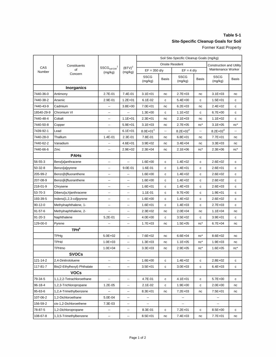
Page 1 of 2
Table 5-1
Site-Specific Cleanup Goals for Soil
Former Kast Property
Inorganics
7440-36-0 Antimony 2.7E-01 7.4E-01 3.1E+01 nc 2.7E+03 nc 3.1E+03 nc
7440-38-2 Arsenic 2.9E-01 1.2E+01 6.1E-02 c 5.4E+00 c 1.5E+01 c
7440-43-9 Cadmium -- 3.8E+00 7.0E+01 nc 6.2E+03 nc 2.4E+02 c
18540-29-9 Chromium VI -- -- 1.3E+00 c 1.1E+02 c 6.7E+00 c
7440-48-4 Cobalt -- 1.1E+01 2.3E+01 nc 2.1E+03 nc 1.1E+02 c
7440-50-8 Copper -- 5.9E+01 3.1E+03 nc 2.7E+05 nc* 3.1E+05 nc*
7439-92-1 Lead -- 6.1E+01 8.0E+013 -- 8.2E+024 -- 8.2E+025 --
7440-28-0 Thallium 1.4E-01 2.3E-01 7.8E-01 nc 6.8E+01 nc 7.7E+01 nc
7440-62-2 Vanadium -- 4.6E+01 3.9E+02 nc 3.4E+04 nc 3.3E+03 nc
7440-66-6 Zinc -- 2.9E+02 2.3E+04 nc 2.1E+06 nc* 2.3E+06 nc*
PAHs
56-55-3 Benz[a]anthracene -- -- 1.6E+00 c 1.4E+02 c 2.6E+02 c
50-32-8 Benzo[a]pyrene -- 9.0E-01 1.6E-01 c 1.4E+01 c 2.6E+01 c
205-99-2 Benzo[b]fluoranthene -- -- 1.6E+00 c 1.4E+02 c 2.6E+02 c
207-08-9 Benzo[k]fluoranthene -- -- 1.6E+00 c 1.4E+02 c 2.6E+02 c
218-01-9 Chrysene -- -- 1.6E+01 c 1.4E+03 c 2.6E+03 c
53-70-3 Dibenz[a,h]anthracene -- -- 1.1E-01 c 9.7E+00 c 1.9E+01 c
193-39-5 Indeno[1,2,3-cd]pyrene -- -- 1.6E+00 c 1.4E+02 c 2.6E+02 c
90-12-0 Methylnaphthalene, 1- -- -- 1.6E+01 c 1.4E+03 c 2.7E+03 c
91-57-6 Methylnaphthalene, 2- -- -- 2.3E+02 nc 2.0E+04 nc 1.1E+04 nc
91-20-3 Naphthalene 5.2E-01 -- 4.0E+00 c 3.5E+02 c 3.9E+01 c
129-00-0 Pyrene -- -- 1.7E+03 nc 1.5E+05 nc* 6.7E+04 nc
TPH6
TPHg 5.0E+02 -- 7.6E+02 nc 6.6E+04 nc* 8.6E+02 nc
TPHd 1.0E+03 -- 1.3E+03 nc 1.1E+05 nc* 1.9E+03 nc
TPHmo 1.0E+04 -- 3.3E+03 nc 2.9E+05 nc* 1.6E+05 nc*
SVOCs
121-14-2 2,4-Dinitrotoluene -- -- 1.6E+00 c 1.4E+02 c 2.8E+02 c
117-81-7 Bis(2-Ethylhexyl) Phthalate -- -- 3.5E+01 c 3.0E+03 c 6.4E+03 c
VOCs
79-34-5 1,1,2,2-Tetrachloroethane -- -- 4.7E-01 c 4.1E+01 c 5.7E+00 c
96-18-4 1,2,3-Trichloropropane 1.2E-05 -- 2.1E-02 c 1.9E+00 c 2.0E+00 nc
95-63-6 1,2,4-Trimethylbenzene -- -- 8.3E+01 nc 7.2E+03 nc 7.5E+01 nc
107-06-2 1,2-Dichloroethane 5.0E-04 -- -- -- --
156-59-2 cis-1,2-Dichloroethene 7.3E-03 -- -- -- --
78-87-5 1,2-Dichloropropane -- -- 8.3E-01 c 7.2E+01 c 8.5E+00 c
108-67-8 1,3,5-Trimethylbenzene -- -- 8.5E+01 nc 7.4E+03 nc 7.7E+01 nc
BasisSSCG
(mg/kg)Basis
SSCG(mg/kg)
Basis
SSCGsoil-GW1
(mg/kg)
Onsite Resident
Soil Site-Specific Cleanup Goals (mg/kg)
Construction and Utility Maintenance WorkerCAS
Number
Constituentsof
Concern
(BTV)2
(mg/kg) EF = 350 d/y EF = 4 d/y
SSCG(mg/kg)

Page 2 of 2
Table 5-1
Site-Specific Cleanup Goals for Soil
Former Kast Property
BasisSSCG
(mg/kg)Basis
SSCG(mg/kg)
Basis
SSCGsoil-GW1
(mg/kg)
Onsite Resident
Soil Site-Specific Cleanup Goals (mg/kg)
Construction and Utility Maintenance WorkerCAS
Number
Constituentsof
Concern
(BTV)2
(mg/kg) EF = 350 d/y EF = 4 d/y
SSCG(mg/kg)
106-46-7 1,4-Dichlorobenzene 3.8E-02 -- 2.8E+00 c 2.4E+02 c 2.8E+01 c
71-43-2 Benzene 1.5E-02 -- 2.2E-01 c 1.9E+01 c 2.2E+00 c
75-27-4 Bromodichloromethane -- -- 4.9E-01 c 4.2E+01 c 5.3E+00 c
74-83-9 Bromomethane -- -- 8.8E+00 nc 7.7E+02 nc 7.8E+00 nc
100-41-4 Ethylbenzene -- -- 4.8E+00 c 4.2E+02 c 5.1E+01 c
75-09-2 Methylene chloride -- -- 5.3E+00 c 4.7E+02 c 5.9E+01 c
75-65-0 tert-Butyl Alcohol 1.2E-02 -- -- -- --
127-18-4 Tetrachloroethene 6.6E-02 -- 5.5E-01 c 4.9E+01 c 1.0E+01 c
108-88-3 Toluene -- -- 4.8E+03 nc 4.2E+05 nc* 1.6E+04 nc
79-01-6 Trichloroethene 1.3E-02 -- 1.2E+00 c 1.0E+02 c 5.5E+00 nc
75-01-4 Vinyl chloride 1.5E-03 -- 3.2E-02 c 2.8E+00 c 3.1E-01 c
1330-20-7 Xylene, total -- -- 5.6E+02 nc 4.9E+04 nc 4.7E+02 nc
Notes:
" -- " not applicable or not available
EF = exposure frequency; d/y = days per year
TPHg = Total Petroleum Hydrocarbons- gasoline range
TPHd = Total Petroleum Hydrocarbons- diesel range
TPHmo = Total Petroleum Hydrocarbons- motor oil range
nc = SSCG based on noncancer effects; c = SSCG based on cancer effects
* Values are above Csat, 1E+05 or Cres
3 Cal-EPA 2009. Revised California Human Health Screening Levels for Lead. September 2009.4 Based on USEPA adult lead model, similar parameters used for the residential CHHSL, and a lower exposure frequency.5 Based on USEPA adult lead model, similar parameters used for the industrial worker CHHSL, and a lower exposure frequency.6 The SSCGsoil-GW for TPH is from the Regional Board’s 1996 Interim Site Assessment & Cleanup Guidebook (RWQCB, 1996a).
1 A SSCGsoil-GW value was only listed for those COCs identified for potential soil leaching to groundwater. These SSCGsoil-GW were
modified from the January 23, 2014 letter from the Regional Board on the Revised SSCG Report (RWQCB, 2014b) to be consistent with the Regional Board’s 1996 Interim Site Assessment & Cleanup Guidebook (RWQCB, 1996a).2 To evaluate potential human health exposures, the higher value between the health-based SSCG and Background Threshold Value (BTV) will be selected as the cleanup goal. To evaluate potential leaching to groundwater, the higher between SSCGsoil-GW and
BTV will be will be selected as the cleanup goal.

Page 1 of 2
Table 5-2
Site-Specific Cleanup Goals for Soil Vapor
Former Kast Property
SSCG(µg/m³)
BasisSSCG(µg/m³)
Basis
79-34-5 1,1,2,2-Tetrachloroethane 5.2E+06 2.1E+01 c 1.2E+05 c
79-00-5 1,1,2-Trichloroethane -- 7.5E+01 c 1.0E+05 nc
75-34-3 1,1-Dichloroethane 6.3E+07 7.6E+02 c 2.5E+07 c
120-82-1 1,2,4-Trichlorobenzene 1.1E+07 1.0E+03 nc 3.9E+05 nc
95-63-6 1,2,4-Trimethylbenzene -- 3.7E+03 nc 2.3E+06 nc
107-06-2 1,2-Dichloroethane 1.2E+06 5.9E+01 c 8.5E+05 c
78-87-5 1,2-Dichloropropane 6.0E+05 1.2E+02 c 2.5E+06 c
108-67-8 1,3,5-Trimethylbenzene -- 3.7E+03 nc 2.3E+06 nc
106-99-0 1,3-Butadiene -- 7.2E+00 c 3.0E+05 c
106-46-7 1,4-Dichlorobenzene 5.5E+05 1.1E+02 c 7.2E+05 c
123-91-1 1,4-Dioxane 3.1E+08 1.6E+02 c 1.6E+05 c
540-84-1 2,2,4-Trimethylpentane -- 5.2E+05 nc 6.5E+08 nc
591-78-6 2-Hexanone -- 1.6E+04 nc 7.9E+06 nc
622-96-8 4-Ethyltoluene -- 5.2E+04 nc 2.5E+07 nc
71-43-2 Benzene 2.4E+06 4.2E+01 c 1.0E+06 c
75-27-4 Bromodichloromethane 5.5E+09 3.3E+01 c 7.8E+05 c
74-83-9 Bromomethane 4.0E+07 2.6E+03 nc 9.5E+06 nc
75-15-0 Carbon disulfide -- 3.7E+05 nc 1.4E+09 nc
56-23-5 Carbon tetrachloride 3.2E+07 2.9E+01 c 1.1E+06 c
67-66-3 Chloroform 2.1E+08 2.3E+02 c 4.9E+06 c
110-82-7 Cyclohexane -- 3.1E+06 nc 1.8E+10 nc
124-48-1 Dibromochloromethane -- 4.5E+01 c 8.8E+05 c
156-59-2 Dichloroethene, cis-1,2- 3.4E+07 3.7E+03 nc 8.3E+06 nc
156-60-5 Dichloroethene, trans-1,2- 3.4E+07 3.1E+04 nc 9.3E+07 nc
10061-02-6 Dichloropropene, trans-1,3- 2.1E+06 7.6E+01 c 3.9E+06 c
64-17-5 Ethanol -- 2.1E+06 nc 1.9E+08 nc
100-41-4 Ethylbenzene 1.0E+06 4.9E+02 c 7.0E+06 c
142-82-5 Heptane -- 3.7E+05 nc 2.3E+09 nc
87-68-3 Hexachloro-1,3-butadiene 6.0E+06 5.5E+01 c 8.0E+04 c
110-54-3 Hexane -- 3.7E+05 nc 1.7E+09 nc
67-63-0 Isopropanol -- 3.7E+06 nc 5.7E+08 nc
98-82-8 Isopropylbenzene (cumene) -- 2.1E+05 nc 1.5E+09 nc
78-93-3 Methyl ethyl ketone (2-butanone) 1.6E+07 2.6E+06 nc 1.1E+09 nc
75-09-2 Methylene chloride 2.8E+08 1.2E+03 c 2.8E+07 c
1634-04-4 Methyl-tert-butyl ether 2.7E+05 4.7E+03 c 6.5E+07 c
91-20-3 Naphthalene 2.2E+05 3.6E+01 c 6.3E+04 c
103-65-1 Propylbenzene -- 5.2E+05 nc 6.6E+08 nc
75-65-0 tert-Butyl Alcohol (TBA) -- 5.5E+05 nc 2.6E+08 nc
127-18-4 Tetrachloroethene 1.6E+07 2.1E+02 c 6.6E+06 c
Soil Vapor
CASNumber
Constituentsof
Concern
Odor-Based
SSCG1
(µg/m³)
Construction andUtility Maintenance Worker
Onsite Resident
Sub-Slab Soil Vapor2

Page 2 of 2
Table 5-2
Site-Specific Cleanup Goals for Soil Vapor
Former Kast Property
SSCG(µg/m³)
BasisSSCG(µg/m³)
Basis
Soil Vapor
CASNumber
Constituentsof
Concern
Odor-Based
SSCG1
(µg/m³)
Construction andUtility Maintenance Worker
Onsite Resident
Sub-Slab Soil Vapor2
109-99-9 Tetrahydrofuran -- 1.0E+06 nc 4.9E+08 nc
108-88-3 Toluene 1.5E+07 2.6E+06 nc 3.7E+09 nc
79-01-6 Trichloroethene 6.8E+08 2.2E+02 c 2.0E+06 nc
75-01-4 Vinyl chloride 3.9E+08 1.6E+01 c 8.3E+05 c
1330-20-7 Xylene, total 2.2E+05 5.2E+04 nc 5.9E+07 nc
TPH
1 Aliphatic: C5-C8 -- 3.7E+05 nc 1.2E+09 nc
2 Aliphatic: C9-C18 -- 1.6E+05 nc 1.2E+08 nc
3 Aliphatic: C19-C32 -- -- -- -- --
4 Aromatic: C6-C8 -- -- -- -- --
5 Aromatic: C9-C16 -- 2.6E+04 nc 6.7E+06 nc
6 Aromatic: C17-C32 -- -- -- -- --
TPHg 5.0E+04 7.2E+04 nc 2.2E+07 nc
TPHd 5.0E+05 8.1E+04 nc 2.3E+07 nc
TPHmo -- -- -- -- --
Notes:
" -- " not applicable or not available
1 Odor-based SSCGs for soil vapor based on SFRWCQB 2013 ESL as directed by RWQCB (RWQCB, 2014b)2 As directed by the RWQCB (RWQCB, 2014b), a vapor intrusion attenuation factor of 0.002 was used to derive sub-slab soil vapor SSCGs.
nc = SSCG based on noncancer effects; c = SSCG based on cancer effects

Geosyntec Consultants Page 1 of 1
Table 5-3Site-Specific Cleanup Goals for Groundwater
Former Kast Property
Inorganics
7440-36-0 Antimony 6.0E+00 -- Bkgd
7440-38-2 Arsenic 1.0E+01 -- Bkgd
7440-28-0 Thallium 2.0E+00 -- Bkgd
PAHs
91-20-3 Naphthalene -- 1.7E+01 1.7E+01
TPH
TPHg -- 4.1E+02 1.0E+02*
TPHd -- 2.0E+02 1.0E+02*
TPHmo -- 6.2E+03 1.0E+02*
VOCs
75-34-3 1,1-Dichloroethane 5.0E+00 -- 5.0E+00
75-35-4 1,1-Dichloroethene 6.0E+00 -- 6.0E+00
96-18-4 1,2,3-Trichloropropane -- 5.0E-03 5.0E-03
107-06-2 1,2-Dichloroethane 5.0E-01 -- 5.0E-01
156-59-2 cis-1,2-Dichloroethene 6.0E+00 -- 6.0E+00
71-43-2 Benzene 1.0E+00 -- 1.0E+00
75-65-0 tert-Butyl Alcohol (TBA) -- 1.2E+01 1.2E+01
127-18-4 Tetrachloroethene 5.0E+00 -- 5.0E+00
156-60-5 trans-1,2-Dichloroethene 1.0E+01 -- 1.0E+01
79-01-6 Trichloroethene 5.0E+00 -- 5.0E+00
75-01-4 Vinyl Chloride 5.0E-01 -- 5.0E-01
106-46-7 1,4-Dichlorobenzene 5.0E+00 -- 5.0E+00
Notes:
" -- " not available
µg/L: micrograms per liter
Bkgd = background
MCL = State of Maximum Contaminant Level for drinking water
NL = Notification Level
ESL = Environmental Screening Levels, San Francisco RWQCB, Region 2
GW = groundwater; SSCG = Site-Specific Cleanup Goal
* Secondary taste and odor threshold for TPH (A Compilation of Water Quality Goals, 16th Edition, April 2011)
CASNumber
Constituentsof
Concern
PrimaryMCL
(µg/L)
Secondary MCL,
NL or ESL (µg/L)
Selected Groundwater
SSCGGW

Soil ExcavationSub-Slab Soil Vapor
MitigationSVE/Bioventing
< 3ft bgs
>3 to <10ft bgs
24401 MARBELLA AVE
24402 NEPTUNE AVE X
24402 PANAMA AVE
24402 RAVENNA AVE X X
24403 NEPTUNE AVE X X
24403 RAVENNA AVE X
24405 MARBELLA AVE
24406 MARBELLA AVE X X
24406 NEPTUNE AVE X X
24406 PANAMA AVE X X
24406 RAVENNA AVE X X
24409 NEPTUNE AVE X X
24409 RAVENNA AVE X
24410 PANAMA AVE
24411 MARBELLA AVE X X
24411 PANAMA AVE X X
24412 MARBELLA AVE X X X
24412 RAVENNA AVE X X
24413 NEPTUNE AVE X X
24413 RAVENNA AVE X
24416 MARBELLA AVE X X
24416 NEPTUNE AVE X X
24416 PANAMA AVE
24416 RAVENNA AVE X X X
24417 MARBELLA AVE
24417 PANAMA AVE X
24419 NEPTUNE AVE X X
24419 RAVENNA AVE X
24420 PANAMA AVE X X
24421 PANAMA AVE X X
24422 MARBELLA AVE X X
24422 NEPTUNE AVE X
24422 RAVENNA AVE X X
24423 MARBELLA AVE
24423 NEPTUNE AVE X X X
24423 RAVENNA AVE X X
24426 MARBELLA AVE X X
24426 NEPTUNE AVE X
24426 PANAMA AVE X X
24426 RAVENNA AVE X X
24427 MARBELLA AVE
24427 PANAMA AVE X
24429 NEPTUNE AVE X X X
Address
Table 6-1
Property Addresses for Consideration in Remedial Planning
Page 1 of 7

Soil ExcavationSub-Slab Soil Vapor
MitigationSVE/Bioventing
< 3ft bgs
>3 to <10ft bgs
Address
Table 6-1
Property Addresses for Consideration in Remedial Planning
24429 RAVENNA AVE X
24430 PANAMA AVE
24431 PANAMA AVE X X
24432 MARBELLA AVE X X
24433 MARBELLA AVE X X X
24436 PANAMA AVE X X
24502 MARBELLA AVE X X
24502 NEPTUNE AVE X
24502 PANAMA AVE
24502 RAVENNA AVE X X
24503 MARBELLA AVE
24503 NEPTUNE AVE X X
24503 PANAMA AVE X X
24503 RAVENNA AVE X
24506 MARBELLA AVE X X X
24507 MARBELLA AVE
24508 NEPTUNE AVE X X
24508 PANAMA AVE X
24508 RAVENNA AVE X X
24509 NEPTUNE AVE X X
24509 PANAMA AVE X X
24509 RAVENNA AVE X X
24512 MARBELLA AVE X X
24512 NEPTUNE AVE X X
24512 PANAMA AVE
24512 RAVENNA AVE X X
24513 NEPTUNE AVE X
24513 PANAMA AVE X X
24513 RAVENNA AVE X X
24516 MARBELLA AVE X X
24517 MARBELLA AVE X X
24518 NEPTUNE AVE X X
24518 PANAMA AVE
24518 RAVENNA AVE X X
24519 NEPTUNE AVE X X
24519 PANAMA AVE X X
24522 MARBELLA AVE X X
24522 NEPTUNE AVE X X
24522 PANAMA AVE
24522 RAVENNA AVE X X
24523 MARBELLA AVE
24523 NEPTUNE AVE X X
24523 RAVENNA AVE X X
Page 2 of 7

Soil ExcavationSub-Slab Soil Vapor
MitigationSVE/Bioventing
< 3ft bgs
>3 to <10ft bgs
Address
Table 6-1
Property Addresses for Consideration in Remedial Planning
24526 MARBELLA AVE X X
24528 NEPTUNE AVE X X
24528 PANAMA AVE
24529 NEPTUNE AVE X X
24529 PANAMA AVE
24529 RAVENNA AVE X X
24532 MARBELLA AVE X X
24532 NEPTUNE AVE
24532 PANAMA AVE X
24532 RAVENNA AVE
24533 MARBELLA AVE
24533 PANAMA AVE
24533 RAVENNA AVE
24602 MARBELLA AVE X
24602 NEPTUNE AVE
24602 PANAMA AVE X
24602 RAVENNA AVE
24603 MARBELLA AVE X X X
24603 NEPTUNE AVE X X
24603 PANAMA AVE X X
24603 RAVENNA AVE X X
24606 MARBELLA AVE X X
24607 MARBELLA AVE X
24608 NEPTUNE AVE X X
24608 PANAMA AVE X X
24608 RAVENNA AVE X X
24609 NEPTUNE AVE X X
24609 PANAMA AVE X X X
24609 RAVENNA AVE
24612 MARBELLA AVE X X
24612 NEPTUNE AVE X X
24612 PANAMA AVE X X
24612 RAVENNA AVE X X
24613 MARBELLA AVE X X
24613 NEPTUNE AVE X X
24613 PANAMA AVE X X X
24613 RAVENNA AVE X X
24616 MARBELLA AVE X X
24617 MARBELLA AVE X X
24618 NEPTUNE AVE X X
24618 PANAMA AVE X X
24618 RAVENNA AVE
24619 NEPTUNE AVE X X
Page 3 of 7

Soil ExcavationSub-Slab Soil Vapor
MitigationSVE/Bioventing
< 3ft bgs
>3 to <10ft bgs
Address
Table 6-1
Property Addresses for Consideration in Remedial Planning
24619 PANAMA AVE X X
24619 RAVENNA AVE X
24622 MARBELLA AVE X X
24622 NEPTUNE AVE X X
24623 MARBELLA AVE X X X
24623 NEPTUNE AVE X X
24627 MARBELLA AVE X X
24628 MARBELLA AVE X X
24628 NEPTUNE AVE X
24629 NEPTUNE AVE X X X
24632 NEPTUNE AVE* X X X
24633 MARBELLA AVE X X
24700 MARBELLA AVE X X
24700 RAVENNA AVE
24702 NEPTUNE AVE X X
24702 PANAMA AVE X X
24703 MARBELLA AVE X X
24703 NEPTUNE AVE X X
24703 RAVENNA AVE X X
24706 MARBELLA AVE X X
24706 RAVENNA AVE X X
24707 MARBELLA AVE
24708 PANAMA AVE X X
24709 NEPTUNE AVE X X X
24709 PANAMA AVE X X
24709 RAVENNA AVE X X
24710 MARBELLA AVE X X
24712 NEPTUNE AVE X X X
24712 PANAMA AVE X X
24712 RAVENNA AVE X X
24713 MARBELLA AVE X X
24713 PANAMA AVE X X
24713 RAVENNA AVE X X
24715 NEPTUNE AVE X X
24716 MARBELLA AVE X X
24716 RAVENNA AVE X X
24717 MARBELLA AVE X X
24718 NEPTUNE AVE X X
24718 PANAMA AVE X X
24719 NEPTUNE AVE X X
24719 PANAMA AVE X X
24719 RAVENNA AVE X X
24722 MARBELLA AVE X X
Page 4 of 7

Soil ExcavationSub-Slab Soil Vapor
MitigationSVE/Bioventing
< 3ft bgs
>3 to <10ft bgs
Address
Table 6-1
Property Addresses for Consideration in Remedial Planning
24722 NEPTUNE AVE X
24722 PANAMA AVE X X
24722 RAVENNA AVE X X
24723 MARBELLA AVE X X X
24723 RAVENNA AVE X X
24725 NEPTUNE AVE
24726 MARBELLA AVE
24726 RAVENNA AVE
24727 MARBELLA AVE X X
24728 NEPTUNE AVE X X
24728 PANAMA AVE X X
24729 NEPTUNE AVE
24729 PANAMA AVE
24729 RAVENNA AVE
24732 MARBELLA AVE X X
24732 NEPTUNE AVE X X
24732 PANAMA AVE
24732 RAVENNA AVE X X
24733 MARBELLA AVE X X
24733 PANAMA AVE
24733 RAVENNA AVE X X
24735 NEPTUNE AVE X X
24736 MARBELLA AVE
24736 RAVENNA AVE X X
24737 MARBELLA AVE X X
24738 NEPTUNE AVE X X X
24738 PANAMA AVE X X
24739 NEPTUNE AVE X X
24739 PANAMA AVE X X
24739 RAVENNA AVE X X
24740 MARBELLA AVE X X
24741 MARBELLA AVE X
24743 RAVENNA AVE X X
24744 MARBELLA AVE X X X
24748 RAVENNA AVE X X
24749 RAVENNA AVE X X X
24752 RAVENNA AVE X X
24802 PANAMA AVE X X
24803 NEPTUNE AVE X X
24803 PANAMA AVE X X
24809 NEPTUNE AVE X X
24809 PANAMA AVE X X
24812 PANAMA AVE
Page 5 of 7

Soil ExcavationSub-Slab Soil Vapor
MitigationSVE/Bioventing
< 3ft bgs
>3 to <10ft bgs
Address
Table 6-1
Property Addresses for Consideration in Remedial Planning
24813 PANAMA AVE X X
24815 NEPTUNE AVE X X
24818 PANAMA AVE X X
24819 PANAMA AVE X X
24822 PANAMA AVE X X
24823 PANAMA AVE X X
24825 NEPTUNE AVE
24828 PANAMA AVE X X
24829 PANAMA AVE X
24832 PANAMA AVE
24833 PANAMA AVE X
24838 PANAMA AVE X X
24904 NEPTUNE AVE X
24912 NEPTUNE AVE X
301 244TH ST
305 244TH ST X X
311 244TH ST X X
317 244TH ST X X
321 244TH ST X X
327 244TH ST
331 244TH ST X X
337 244TH ST
341 244TH ST
344 249TH ST X X
345 249TH ST X
347 244TH ST
348 248TH ST X X X
348 249TH ST X
351 244TH ST X X
352 249TH ST X X
353 249TH ST X X
354 248TH ST X X
357 244TH ST
357 249TH ST X
358 249TH ST X X
360 248TH ST X X
361 244TH ST
362 249TH ST
363 249TH ST X
364 248TH ST X X
367 244TH ST X X
367 249TH ST X
368 249TH ST X X
Page 6 of 7

Soil ExcavationSub-Slab Soil Vapor
MitigationSVE/Bioventing
< 3ft bgs
>3 to <10ft bgs
Address
Table 6-1
Property Addresses for Consideration in Remedial Planning
373 249TH ST X X
374 248TH ST X X
374 249TH ST X X
377 244TH ST
377 249TH ST X X
378 249TH ST X X X
383 249TH ST X X X
402 249TH ST X X
408 249TH ST
412 249TH ST X X
"X" - Included based on Human Health and/or Soil Leaching to Groundwater Evaluation in HHRA
Soil excavation scenario based on ≤ 5 feet below ground surface (bgs) evaluation in HHRA
SVE/Bioventing scenario based on both ≤ 5 feet bgs and > 5 to ≤ 10 feet bgs evaluation in HHRA
Soil vapor excluding background contribution of THMs
* Property identified for sub-slab mitigation based on methane detection at 0.58%, slightly above the methane SSCG of 0.5%
Page 7 of 7