Relazione tecnica - intestazione 2 - Essiccatoi per Cereali - Grain Dryers...
13
OFFICINE MINUTE VILLORBA - TREVISO
Transcript of Relazione tecnica - intestazione 2 - Essiccatoi per Cereali - Grain Dryers...
OFFICINE MINUTEVILLORBA - TREVISO

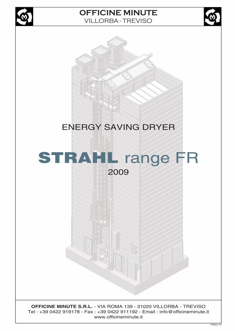
“STRAHL” DRYER RANGE FR
Pag 1 di 12
A9 - Recycled air channel
A11 - Dried grain hopper
A8 - Cooling zone
A5 - Exhaust air plenumA7 - 2° Drying zone
A4 - 1° Drying zone
A10 - Wet grain hopper
A12 - Main fans ( upper )
A3 - Hot air plenumA2 - Air mixing areaA1 - Linear gas burner
A14
A19 - Burner protection panelsA20 - Dried grain extraction augerA21 - Internal inspection platforms
A23 - External stair and platforms
zone regulationA18 - Stainless steel flame-break panel
A17 - Movable panel for cooling
A15 - Anti-rain shuttersA16 - Cooling air regualtion shutter
A22 - Roof
A20
A8
A11
A21
A16
A19
A5
A14
A15
A12
A7
A21A17
A21
A21
A18
A9
A2
A10
A4
A21
A23
A3
A22 A23
A13
A13 - Recycled air fans ( lower )A14 - Anti-dust shutters
A24
A24 - Extraction device
A25
A25 - Wet grain distribution auger
A1
Air distribution chambers
Thermal insulation
Aluzinc panels
Galvanised steel panels
Welded strengthening profiles
Aluzinc panel
Outer panelMineral woolLayer
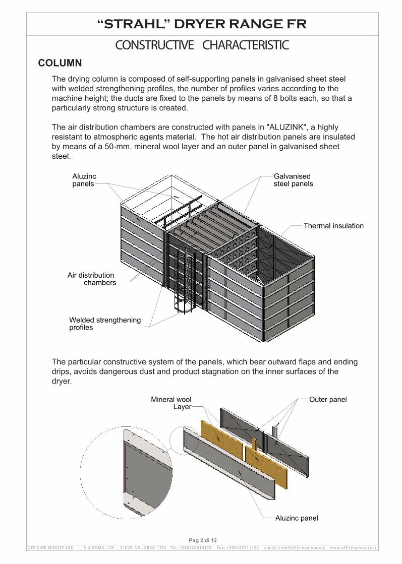
The drying column is composed of self-supporting panels in galvanised sheet steel with welded strengthening profiles, the number of profiles varies according to the machine height; the ducts are fixed to the panels by means of 8 bolts each, so that a particularly strong structure is created.
The air distribution chambers are constructed with panels in "ALUZINK", a highly resistant to atmospheric agents material. The hot air distribution panels are insulated by means of a 50-mm. mineral wool layer and an outer panel in galvanised sheet steel.
COLUMN
“STRAHL” DRYER RANGE FR
The particular constructive system of the panels, which bear outward flaps and ending drips, avoids dangerous dust and product stagnation on the inner surfaces of the dryer.
Pag 2 di 12

Recycled air fans
Extraction device
Dreied grain hopper
The extraction device and the dry grain collection hopper are built in the monoblock base; the hopper is placed in an elevated position so that the air to be recycled can flow through, and that it is possible to thoroughly clean the bottom.
FANS
“STRAHL” DRYER RANGE FR
The used fans are axial flow fans with a diameter of 1000 mm.; the steel rotor is directly connected to the motor, thus avoiding power losses due to transmission; a row of flux rectifiers is placed below the rotor; they support the motor and consent the recuperation of the dynamic pressure created by the rotating movement transmitted to the blades, thus increasing performance.
The particular construction of these fans, and the rather high rotor diameter / fan diameter ratio, make it possible to reach a sufficient pressure even if 6 pole motors (approximately 960 turns per minute) are used, thus allowing a drastic reduction of noise.

There are two versions, according to the used burner:
Version BT using traditional burners
One or more direct fire furnaces are mounted in vertical position, in order to reduce encumbrance; they can be used with pressurised diesel, natural gas or GPL.
Particular care is used in the construction of the stainless steel combustion cham-bers, in order to obtain the maximum possible mixing of combustion smokes and air. The main chamber body is cylindrical, and the two ends have a cone-shape, this allows the absorption of the expansion caused by air variations.
HEATING GENERATOR
“STRAHL” DRYER RANGE FR
Pag 4 di 12
Anti-dust shutter
Anti-rain shutter
Fan
Extraction extension
Pick up patternpoint
Air inlet
The extraction extension has an air inlet which allows the motor cooling using fresh air from outside; moreover the inside walls are covered with a layer of 80 density rock wool which allows a further reduction of noise.
Each fan is connected to a pneumatically operated interception shutter with aerody-namic flaps.

The chamber end is closed. Smokes escape through eight lateral staggered ducts and are directed toward the furnace lateral areas where they are mixed with the cooler air through special deflectors.
In this way we obtain a particularly homogeneous temperature and avoid the forma-tion of dangerous exceedingly hot air veins.
After they have been mixed with the recycle air, they pass through. a row of pierced panels, which create a turbulence and allow a better temperature homogeneity.
Version VA with air vein burners
Natural gas or GPL air vein burners are used for combustion; this solution allows a better heat distribution, if compared with the one obtained with traditional pressurised burners.
The speed of the air on the burner is adjusted through 2 adaptable deflectors; a stainless steel panel is mounted right above the burner, in order to cut the flame and avoid strings of exceedingly hot air.
The hot air spreads inside a vertical and very wide duct, which is insulated thanks to mineral wool and galvanised panels.
After it has been mixed with the recycle air, it flows through. a row of pierced panels, which create a better mixing, improving temperature homogeneity.
“STRAHL” DRYER RANGE FR
Pag 5 di 12

The extraction device allows the fall of a large quantity of grain in very short times, avoids pollution problems when product is changed, and eliminates the danger of obstructions creation even in presence of foreign bodies.
At the end of the column the product is directed through parallel ducts; a swinging shutter is placed under each duct, and, when it is in normal position, it prevents the product from falling.
All the shutters are connected to each other by means of two strong rods, on which end is a torsion bar, well fixed by means of three spherical centre bearings.
An air activated piston causes the rotation of the bar, thus determining the opening of the shutters, and the consequent fall of the product into the hopper situated below. This movement is extremely rapid (from half a second to one second).
The whole system has been dimensioned in order to obtain a free space between the fix ducts and the swinging shutters, thus reducing almost completely the risk of obstruction creation caused by the presence of foreign bodies.
EXTRACTION DEVICE
“STRAHL” DRYER RANGE FR
Pag 6 di 12
SCHEME OF OPERATION OFEXTRACTION DEVICE
Rods Swinging shutters
Grain
CLOSED
OPEN

Every detail has been studied for the easy main-tenance and the cleaning of the machine.
A series of ladder , with plain of rest for the more long route , allow the access to a comfortable platform and to two floors for the control of the supe-rior shutters and wet grain hopper.
On the two sides of the column there are previewed comfortable plans of job for cleaning every angle of column ; the plans are positioned to a height of 2,5 meters from each other and they are completely protected against the fall; a series of ladder allow the passage from one to the other throught a safety trap door.
Two ample doors allow the access to the lower part of the drier. The zone the burner is protect from a grilled antirain.
MAINTENANCE
“STRAHL” DRYER RANGE FR

The product falls by gravity and passes through staggered layers of ducts which cause a zigzag movement and a constant mixing; the ducts design and the extrac-tion by impulses allow a uniform fall along the whole column section, thus avoiding the formation of preferential streams.
In the first drying area the product is hit by hot air and releases the higher part of humidity. Between the first and the second drying area the product passes through a resting area, where it is not treated by any air flow. While in this area the most inner grain humidity tends to migrate toward the outer part, making the following evapora-tion easier and improving drying homogeneity.
In the second drying area the remaining humidity is released, until when the product reaches the requested final value.
The width of the final cooling area is adjustable and can be increase or reduced to suit the product to be treated, the operating temperature and the environmental conditions. Moreover the cooling air quantity can be adjusted by means of the spe-cial shutters.
In case of drying operations with separate cooling (dryeration) it is possible to use the whole cooling area for the drying procedure.
PRODUCT HANDLING
“STRAHL” DRYER RANGE FR
Pag 8 di 12
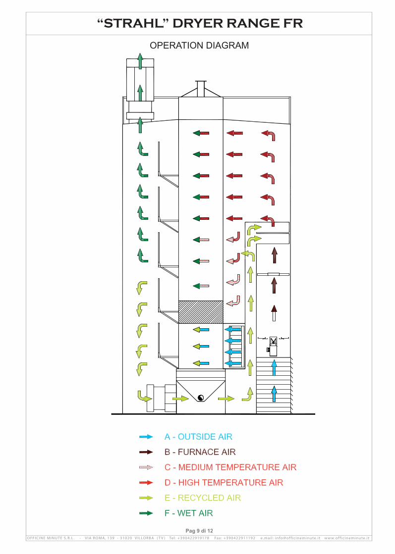
AIR CIRCUIT
The air movement is guaranteed by one or more fans placed in the lower part of the air collection chamber and by one or more fans placed in the higher part.
The higher ventilators draw in the air arriving from the upper part of the column; in this area the product is still humid, the air is saturated and is therefore discharged in the atmosphere.
The lower fans draw in the air arriving from the lower part of the drying area, where the air is warm and not completely saturated, and from the cooling area, where the air contains the heat extracted from the product.
This air passes through the column, under the base and is directed upwards through a duct.
“STRAHL” DRYER RANGE FR
Pag 9 di 12
OPERATION DIAGRAM
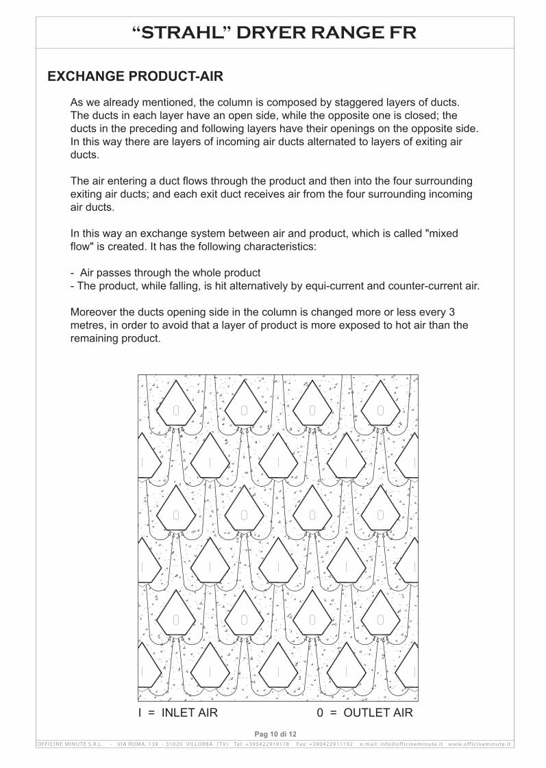
I = INLET AIR 0 = OUTLET AIR
As we already mentioned, the column is composed by staggered layers of ducts. The ducts in each layer have an open side, while the opposite one is closed; the ducts in the preceding and following layers have their openings on the opposite side. In this way there are layers of incoming air ducts alternated to layers of exiting air ducts.
The air entering a duct flows through the product and then into the four surrounding exiting air ducts; and each exit duct receives air from the four surrounding incoming air ducts.
In this way an exchange system between air and product, which is called "mixed flow" is created. It has the following characteristics:
- Air passes through the whole product- The product, while falling, is hit alternatively by equi-current and counter-current air.
Moreover the ducts opening side in the column is changed more or less every 3 metres, in order to avoid that a layer of product is more exposed to hot air than the remaining product.
EXCHANGE PRODUCT-AIR
“STRAHL” DRYER RANGE FR
Pag 10 di 12
IN ORDER TO LIMIT DUST EMISSION SOME CONSTRUCTIVE ARRANGEMENTS HAVE BEEN ADOPTED.
OPERATING IN DEPRESSION
“STRAHL” DRYER RANGE FR
Pag 11 di 12
First of all the dryer is set in depression and the saturated air is collected by a line of fans and is easily directed; so there aren’t diffused emission in the place of work.
MOVEMENT OF THE PRODUCT
If we observe a dryer in operation we can easily note that the dust emission is higher when the product is moving; if the product is not moving, dust emission is indeed low; That is why we have taken particular care in order to reduce product movement and air speed during this phase.
First of all the column extraction device, described earlier, has been designed in order to allow the extraction of a large quantity of product in a very short time.
The extraction speed is such that, in reality, the total extraction time of this dryer is about 20 - 40 second per hour; only during this extractions take place a significant dust emission.
A few tenth of a second before extraction the shutters are closed so that the air flow is completely blocked; a few seconds after extraction, when the product has comple-ted its fall and its movement, they are gradually opened.
The control panel allows setting of advance and delay times for each shutter.
AIR SPEEDDust emission is caused by the passage of air through the product; air collects the lighter particles. Logically, the faster the air is, the higher the emitted parti-cles quantity is.
For this reason we have built some canals for crossing air with a big entrance surfa-ce of the air with the product, in such canal flows about 70 mc/h of air and the exhibit surface of the product is 0,37 mq; the speed of the exit air consequently is 5,2 cm/sec, a vary low value.
An optimal air circulation is assured by the presence of rather large distribution chambers, which allow avoiding the presence of faster air flows; moreover the ducts design allows a reduced air speed when it enters and when it flows through the product.

RECYCLE OF THE NO-SATURATED
“STRAHL” DRYER RANGE FR
Pag 12 di 12
We can moreover easily note that, in the areas where the product is humid, dust emission is much lower than in the areas where the product is dry.
The particular air circuit of this dryer, which has been designed also to reduce fuel consumption, allows further reduction of dust emission.
The upper fans extract air arriving from the upper part of the column; the content of impurities in this air is low; in fact it has passed through the grain in the more humid zone, and the above-indicated arrangements have reduced dust emission.
The lower fans extract air arriving from the lower part of the column; the content of impurities in this air is higher, but it is recycled through ducts, and flows again throu-gh the product in the upper part or the column, where the product acts as air filter.
That means that only approximately 2/3 of the air necessary for drying are emitted into the environment, while the air having a higher content of dust is recycled.
SAMPLING OF THE EMISSIONS The sampling of the emissions can happen in the advanced plan of the dryer where the chimney are present; the access to this plan is concurred through a ladder with the duffle-coat mounted on one of two sides and equipped of intermediate plans of rest so as to not to have a advanced draft to the 7,5 meters.
On every chimney there is 2 pick up point 3” male, orthogonal each other , predispo-sed for the sampling probes.


![9a Intestazione Bibliografiatesionline.unicatt.it/bitstream/10280/1795/14/06 bibliografia_tesiphd... · Pionieri cristiani della democrazia, Città Nuova, Roma 20083 [Seli, Roma 1945]](https://static.fdocuments.net/doc/165x107/60c12ca7e86c4368ea774d28/9a-intestazione-bi-bibliografiatesiphd-pionieri-cristiani-della-democrazia.jpg)