Reflection Grating Spectrometers An Enabling Technology Response
10
Reflection Grating Spectrometers – An Enabling Technology Response to the Concepts for the Next NASA X-ray Astronomy Missions RFI, Solicitation: NNH11ZDA018L Submitter: Randall L. McEntaffer, Asst. Professor, University of Iowa, Department of Physics and Astronomy, 704 Van Allen Hall, Iowa City, IA 52242, 319-335-3007, [email protected] Co-authors: Webster Cash, University of Colorado, [email protected] Ralf Heilmann, MIT, [email protected] Andrew Holland, the Open University (UK), [email protected] Chuck Lillie, Northrop Grumman Aerospace Systems, [email protected] Phil Oakley, MIT, [email protected] Stephen O’Dell, Marshall Space Flight Center, steve.o’[email protected] Mark Schattenburg, MIT, [email protected] William Zhang, Goddard Space Flight Center, [email protected] Category of response: Enabling technology – reflection grating spectrometer to meet the high resolution, large effective area requirements at 0.3-1.0 keV. Instrument concept – the Off-Plane X-ray Grating Spectrometer (OP-XGS) concept utilized for the International X-ray Observatory (IXO) and applications to other missions. i. Members of the team are willing to participate and present at a future workshop. ii. This response contains no sensitive or controlled information. Executive Summary An X-ray grating spectrometer is capable of achieving key science goals of IXO that are described in the 2010 Astrophysics Decadal Survey and outlined in the table of primary IXO science objectives included in the RFI. More specifically, high spectral resolution (R > 3000, λ/Δλ) and large effective area (> 1000 cm 2 ) are required to answer the question: “How does large scale structure evolve?” There is an abundance of emission and absorption lines of highly ionized astrophysical plasmas at the lowest X-ray energies, 0.3-1.0 keV. Grating spectrometers have dispersion that is constant in wavelength such that resolution increases with decreasing energy. Non-dispersive spectrometers such as microcalorimeters have resolution that is constant in energy leading to a decrease in spectral resolution with decreasing energy. Future X-ray missions may utilize microcalorimeters to obtain high spectral resolution at higher energies, but must also include a dispersive spectrometer to adequately resolve the wealth of important spectral lines in the soft energy band. A major goal of IXO was to find the missing baryons in the universe that exist in the enriched filaments of gas extending between galaxies in a cosmic web. Detection of the baryons is achieved through sensitive observations of sightlines to AGN to find absorption features due to the filaments. The dominant lines of highly ionized C, N, O, Ne, etc. occur at energies < 1 keV thus requiring a grating spectrometer to detect these filaments with high significance. The enrichment of these filaments is most likely accomplished via galactic outflows. Determining the kinematics of outflows using high resolution spectroscopy will also aid in our understanding of large scale structure evolution. Two grating concepts have been studied in depth to address these IXO science goals. One design is the Off-Plane X-ray Grating Spectrometer (OP-XGS) and is described in this document. The other is the Critical Angle Transmission Grating Spectrometer (CAT) and is described in detail in another document (Heilmann, et al. this solicitation). These two documents are presented as a concerted effort to emphasize the importance of grating spectrometers to future X-ray missions. A grating spectrometer is critical to any mission requiring high resolution, high throughput spectroscopy at soft X-ray energies. Here we describe the design, capability, and applications of a grating spectrometer utilizing reflection gratings in the off-plane mount. This concept allows for high efficiency and resolution in a modular package that is adaptable to a variety of configurations and therefore mission architectures. As such, this
Transcript of Reflection Grating Spectrometers An Enabling Technology Response

Reflection Grating Spectrometers – An Enabling Technology Response to the Concepts for the Next
NASA X-ray Astronomy Missions RFI, Solicitation: NNH11ZDA018L
Submitter: Randall L. McEntaffer, Asst. Professor, University of Iowa, Department of Physics and
Astronomy, 704 Van Allen Hall, Iowa City, IA 52242, 319-335-3007, [email protected]
Co-authors:
Webster Cash, University of Colorado, [email protected]
Ralf Heilmann, MIT, [email protected]
Andrew Holland, the Open University (UK), [email protected]
Chuck Lillie, Northrop Grumman Aerospace Systems, [email protected]
Phil Oakley, MIT, [email protected]
Stephen O’Dell, Marshall Space Flight Center, steve.o’[email protected]
Mark Schattenburg, MIT, [email protected]
William Zhang, Goddard Space Flight Center, [email protected]
Category of response: Enabling technology – reflection grating spectrometer to meet the high resolution,
large effective area requirements at 0.3-1.0 keV. Instrument concept – the Off-Plane X-ray Grating
Spectrometer (OP-XGS) concept utilized for the International X-ray Observatory (IXO) and applications
to other missions.
i. Members of the team are willing to participate and present at a future workshop.
ii. This response contains no sensitive or controlled information.
Executive Summary
An X-ray grating spectrometer is capable of achieving key science goals of IXO that are described in
the 2010 Astrophysics Decadal Survey and outlined in the table of primary IXO science objectives
included in the RFI. More specifically, high spectral resolution (R > 3000, λ/Δλ) and large effective area
(> 1000 cm2) are required to answer the question: “How does large scale structure evolve?” There is an
abundance of emission and absorption lines of highly ionized astrophysical plasmas at the lowest X-ray
energies, 0.3-1.0 keV. Grating spectrometers have dispersion that is constant in wavelength such that
resolution increases with decreasing energy. Non-dispersive spectrometers such as microcalorimeters
have resolution that is constant in energy leading to a decrease in spectral resolution with decreasing
energy. Future X-ray missions may utilize microcalorimeters to obtain high spectral resolution at higher
energies, but must also include a dispersive spectrometer to adequately resolve the wealth of important
spectral lines in the soft energy band. A major goal of IXO was to find the missing baryons in the
universe that exist in the enriched filaments of gas extending between galaxies in a cosmic web.
Detection of the baryons is achieved through sensitive observations of sightlines to AGN to find
absorption features due to the filaments. The dominant lines of highly ionized C, N, O, Ne, etc. occur at
energies < 1 keV thus requiring a grating spectrometer to detect these filaments with high significance.
The enrichment of these filaments is most likely accomplished via galactic outflows. Determining the
kinematics of outflows using high resolution spectroscopy will also aid in our understanding of large
scale structure evolution.
Two grating concepts have been studied in depth to address these IXO science goals. One design is
the Off-Plane X-ray Grating Spectrometer (OP-XGS) and is described in this document. The other is the
Critical Angle Transmission Grating Spectrometer (CAT) and is described in detail in another document
(Heilmann, et al. this solicitation). These two documents are presented as a concerted effort to emphasize
the importance of grating spectrometers to future X-ray missions. A grating spectrometer is critical to
any mission requiring high resolution, high throughput spectroscopy at soft X-ray energies.
Here we describe the design, capability, and applications of a grating spectrometer utilizing reflection
gratings in the off-plane mount. This concept allows for high efficiency and resolution in a modular
package that is adaptable to a variety of configurations and therefore mission architectures. As such, this

spectrometer represents a key Enabling Technology for any future X-ray mission with WHIM studies as a
scientific goal.
1. Description of the OP-XGS concept
The IXO baseline configuration included an X-ray Grating Spectrometer (XGS) instrument. The
purpose of the IXO XGS is to provide high spectral resolution, λ/Δλ > 3000, and high effective area,
>1000 cm2, at low energies 0.3-1.0 keV. This represents more than an order of magnitude increase in
effective area together with an increase of approximately an order of magnitude in resolving power over
previous observatories. This large increase in performance will open up new discovery space, and in
particular will address key scientific questions such as measurements of the WHIM and dynamics in
galactic outflows as outlined in Section 4.
One concept for the IXO XGS is a reflection grating design known as the Off-Plane X-ray Grating
Spectrometer (OP-XGS; McEntaffer et al. 2010). The work on this concept began during Constellation-X
and continued into IXO. The design utilizes an array of gratings placed in a converging telescope beam
in the off-plane configuration with a CCD camera for the readout. The technologies are very similar to
those utilized for XMM-Newton and also have heritage in suborbital rocket missions. The grating array
intercepts a small portion of the main telescope beam (approximately 13% for IXO) and diffracts the light
onto an array of dedicated CCDs. It is important to note that the gratings were only allowed to cover the
section of the beam required to meet the 1000 cm2 requirement. In this way they would not intercept the
entire beam (or any of the high energy, inner telescope shells) allowing most of the light to pass to the
primary focus, typically sampled by the microcalorimeter. However, if the gratings were allowed to
cover the entire beam then a factor of ~8 improvement could be made in the XGS effective area. The
decreased form factor did allow for increased flexibility in the placement of the grating array. The off-
plane configuration is capable of meeting the instrument performance requirements at any position along
the IXO optical axis from just aft of the optics (focal length = ~19 m) to just a few meters away from the
focal plane. This parameter space has been studied in depth to achieve an optimal configuration for the
last IXO spacecraft design in which the grating array is placed 5.16 m from the focal plane via the use of
a lightweight structural tower. This large parameter space would exist for an OP-XGS placed in any X-
ray focusing telescope lending much flexibility to the design. Furthermore, if the gratings are actuated in
and out of the beam such as those onboard Chandra, then the effective area of the grating spectrometer
could be much greater. This allows for the OP-XGS to be applicable to nearly any X-ray mission
requiring soft X-ray spectroscopy.
An example IXO OP-XGS layout is shown in Figure 1. This configuration was intended for IXO and
described in detail here, but could easily be adapted to another mission architecture. This particular
concept is comprised of a grating array mounted upon a rigid lightweight tower which itself is mounted
on the instrument platform. A tower was included in the IXO design given the lack of pre-existing
observatory structure at this distance. Other options included mounting the gratings directly onto the
mirror modules or other observatory structures such as an avionics bus. However, the tower offered some
advantages such as smaller grating and CCD arrays. The tower can also serve as support for a stray light
baffle, magnetic particle deflectors, contamination mitigating cold plates and other system resources, thus
providing a mass savings for the observatory. The length of the tower can be tuned to meet the
observatory design. The grating array diffracts the intersected beam into several arcs, or spectra, onto a
fixed CCD camera. The camera is mounted on the instrument platform and consists of an array of CCDs
with associated electronics, thermal control and radiation, stray light and contamination shielding.
The Grating System consists of a Grating Array made from 6 separate, yet identical, modules as
visible on the bottom left detail of Figure 1. These grating modules are mounted to the top of the Grating
Tower along with an independent thermal control system. Each of the 6 modules contains 23 gratings
that differ only by their width and are co-aligned to form a single spectrum per module. The module
mounts and grating substrates are machined Be to provide a stiff, lightweight structure with minimal
thermal differences. The average mass of each grating is ~20 g giving a total grating mass of < 3 kg. The
module mounts are of comparable total mass at 3 kg as well. The array structure that holds the modules

and thermal system in place is 5 kg. The grating array is quite light at only 11 kg of mass. The main
mass contribution is the tower structure; however this only adds 20 kg of mass. This tower could be
avoided given preexisting mounting infrastructure, but it results in a significant mass savings to the
system by providing a mounting structure for system resources such as the baffle, magnetic diverters, etc.
For other X-ray missions the mass of the grating array can be kept quite low. The area of beam coverage
for the entire array is ~67° of azimuth (~19%) on the outer ~50% of telescope radii.
Figure 1: Schematic of the OP-XGS concept design. Six grating modules (bottom left) are placed on a
tower assembly extended from the instrument platform which also houses the readout CCD camera
(bottom right).
The grooves on these gratings lie nearly parallel to the direction of the incoming X-rays (the off-plane
mount) and exhibit a radial, blazed, high density profile that allows them to obtain high throughput and
high resolution. A key element in the instrument design is the detailed layout and groove specification of
the gratings themselves. The fabrication of the gratings is achieved through industrial processes. The
details of this fabrication form the main goal of technology development toward this type of spectrometer.
This is discussed below in Sections 2 and 3.
The temperature requirement for the gratings is 293 ± 1K for bulk temperature and temperature
gradients across the array. The temperature control system consists of 2 heaters, a radiative panel and
several thermistors per each of the 6 modules. The control card will live in a CCD electronics box with
harness as the major mass contributor. The entire thermal system mass estimate is < 7 kg. The nominal
power usage to maintain the grating operating temperature is 5 W with peak power usage of 19 W during
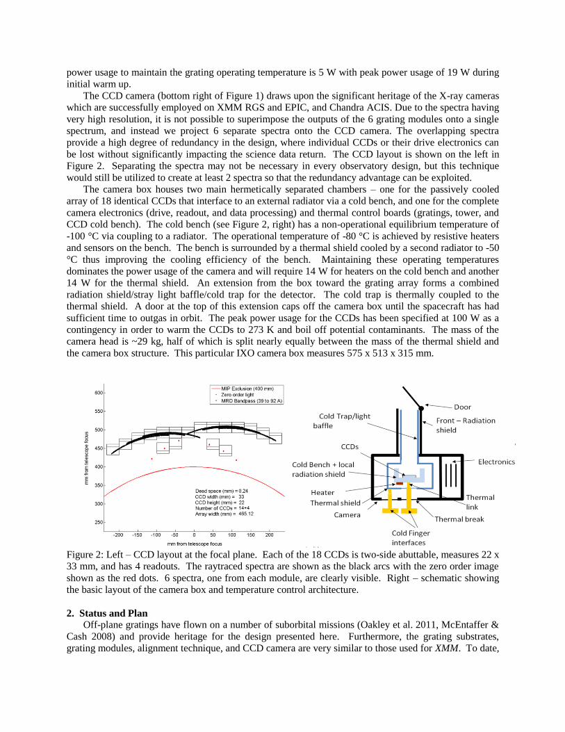
initial warm up. The CCD camera (bottom right of Figure 1) draws upon the significant heritage of the X-ray cameras
which are successfully employed on XMM RGS and EPIC, and Chandra ACIS. Due to the spectra having
very high resolution, it is not possible to superimpose the outputs of the 6 grating modules onto a single
spectrum, and instead we project 6 separate spectra onto the CCD camera. The overlapping spectra
provide a high degree of redundancy in the design, where individual CCDs or their drive electronics can
be lost without significantly impacting the science data return. The CCD layout is shown on the left in
Figure 2. Separating the spectra may not be necessary in every observatory design, but this technique
would still be utilized to create at least 2 spectra so that the redundancy advantage can be exploited.
The camera box houses two main hermetically separated chambers – one for the passively cooled
array of 18 identical CCDs that interface to an external radiator via a cold bench, and one for the complete
camera electronics (drive, readout, and data processing) and thermal control boards (gratings, tower, and
CCD cold bench). The cold bench (see Figure 2, right) has a non-operational equilibrium temperature of
-100 °C via coupling to a radiator. The operational temperature of -80 °C is achieved by resistive heaters
and sensors on the bench. The bench is surrounded by a thermal shield cooled by a second radiator to -50
°C thus improving the cooling efficiency of the bench. Maintaining these operating temperatures
dominates the power usage of the camera and will require 14 W for heaters on the cold bench and another
14 W for the thermal shield. An extension from the box toward the grating array forms a combined
radiation shield/stray light baffle/cold trap for the detector. The cold trap is thermally coupled to the
thermal shield. A door at the top of this extension caps off the camera box until the spacecraft has had
sufficient time to outgas in orbit. The peak power usage for the CCDs has been specified at 100 W as a
contingency in order to warm the CCDs to 273 K and boil off potential contaminants. The mass of the
camera head is ~29 kg, half of which is split nearly equally between the mass of the thermal shield and
the camera box structure. This particular IXO camera box measures 575 x 513 x 315 mm.
Figure 2: Left – CCD layout at the focal plane. Each of the 18 CCDs is two-side abuttable, measures 22 x
33 mm, and has 4 readouts. The raytraced spectra are shown as the black arcs with the zero order image
shown as the red dots. 6 spectra, one from each module, are clearly visible. Right – schematic showing
the basic layout of the camera box and temperature control architecture.
2. Status and Plan
Off-plane gratings have flown on a number of suborbital missions (Oakley et al. 2011, McEntaffer &
Cash 2008) and provide heritage for the design presented here. Furthermore, the grating substrates,
grating modules, alignment technique, and CCD camera are very similar to those used for XMM. To date,

the technology development specific to IXO has concentrated on meeting the efficiency and resolution
requirements for the gratings. A combination of analytical predictions, extensive raytracing, and
laboratory demonstrations show that the design is capable of obtaining the performance requirements.
Theoretical calculations of grating efficiency performed independently by the grating manufacturer,
Horiba Jobin-Yvon, and our team give expected efficiencies at the 50% level, sum of orders. Using a
radial, blazed, high density prototype grating we have empirically obtained grating efficiencies >40%,
thus approaching theoretical (McEntaffer, et al. 2004). The current design provides >1000 cm2 of
effective area from 0.3-1.0 keV with an average area of > 1500 cm2 over this same band, assuming a 40%
grating efficiency. An example of the efficiency testing facilities is shown in Figure 3.
Figure 3: Left – Test grating in the University of Colorado X-ray Test Facility. Right – Test grating in the
University of Iowa Facility.
Figure 4: The MSFC Stray Light Facility large vacuum chamber with test optics. In the upper left of the
image a single parabola and hyperbola are held in a kinematic mount. The test grating apparatus is
located on right side of the image with 4-axis motion control.
Raytrace analysis of the design gives a theoretical resolution of 9000 (λ/Δλ) at 1 keV in 3rd
order.
Using a radial, blazed grating we have empirically achieved a resolution of >200 at 1 keV with a 3’
telescope (Osterman, et al. 2004). Extrapolation to a 5” telescope gives a spectral resolution of 7200, well
above the requirement of 3000 over the bandpass. An example of an off-plane grating in a resolution test
setup, complete with GSFC slumped glass Wolter optics, is shown in Figure 4. This configuration, along

with a soft X-ray CCD camera (not shown), was recently used in testing at the MSFC Stray Light
Facility.
Figure 5: A high fidelity Be grating substrate assembled with a Be grating module mount. The image on
the left shows the polished reflective surface while the image on the right is the lightweighted back side.
All tests have been performed in a relevant environment in terms of temperature and pressure with X-
rays, but vibration tests have not yet been performed.
Development has continued in structural modeling and fabrication. Specifically, high fidelity grating
substrates and grating module mounts have been fabricated. Figure 5 shows an assembly of a single
grating substrate in a module mount. All parts shown are precision machined Be providing a lightweight,
stiff assembly with no CTE mismatch. The grating substrates have a polished Ni surface with a λ/4 figure
and <1 nm roughness. The substrate profile is trapezoidal and lightweighted on the back as seen on the
right side of the image. These substrates are very similar in form and function to those in the XMM-RGS.
The proposed OP-XGS concept design incorporates identical substrates in terms of material, size, mass,
and surface quality. The module design provides 6 degrees of freedom for manipulation of the gratings.
This prototype design allows for 3 gratings to be aligned. Alignment protocols, metrology, and testing
are the next steps in module technology development.
Figure 6: Left – effective area curve for the OP-XGS showing effective area > 1000 cm
2 over the 0.3-1.0
keV band with ~1500 cm2 average area over the same band. The notches in the curve are due to the gaps
between CCDs. Right – resolution as a function of wavelength. 1st, 2
nd, and 3
rd orders are required to
maintain R > 3000 over the band.

Figure 6 displays the analytical calculations of effective area and resolution for the OP-XGS. The
efficiency calculations use a maximum of 40% grating efficiency, detailed analysis of the telescope
throughput as a function of energy, and well known efficiency curves for the CCD response. The
resolution calculations are based on detailed raytraces of all optical elements as a function of wavelength.
Given the analytical predictions and preliminary empirical results verifying some of our predictions, we
have assessed the OP-XGS concept at TRL 3.
3. Development Milestones
The two key technology development efforts for the OP-XGS will be in grating fabrication and
optical filtering of the CCDs.
The grating fabrication development begins with the fabrication and testing of a flight prototype
grating master. The grating will have a radial groove profile with high density (5500 grooves/mm) blazed
(18-24°) gratings. Fabrication of such a profile is currently difficult. The problems lie in producing a
high quality radial profile and precision etching of large areas. Horiba Jobin-Yvon (JY) is a grating
manufacturer that uses holographic recording and ion etching to produce custom gratings for many
suborbital rocket gratings and the majority of test gratings procured during the Constellation-X and IXO
studies. Through these studies we have developed tools that have begun to surmount the fabrication
challenges, although more development work must be done. This includes controlling the radial profile
and etching process over larger areas and higher groove densities. In addition to this process, Mark
Schattenburg and Ralf Heilmann at MIT have produced high density parallel groove blazed gratings that
have atomically smooth grating facets. They have also used nanoimprint lithography to efficiently
replicate these gratings with high fidelity. The challenge here is in the production of a radial groove
profile. Development in this area may include merging the techniques of JY and MIT to produce a new
method for grating fabrication. In the MIT method, the high density groove profile is created using
interference lithography to produce a laminar pattern in the resist layer. Subsequent reactive ion etching
and anisotropic wet etching transfer this pattern into an off-cut Si wafer thus producing the blazed profile.
The problem is the inability of producing a radial profile via this particular interference lithography setup.
This may be circumvented by using a radial laminar grating produced by JY with nanoimprint lithography
to transfer the pattern into the resist. These grating master fabrication techniques must be studied to
increase the TRL of the OP-XGS and are one of the main goals of a recent Strategic Astrophysics
Technology grant.
X-ray efficiency and spectral resolution verification tests on this master and replicas of the master are
necessary to demonstrate TRL 4. Replicas will be imprinted onto medium fidelity grating substrates.
Efficiency testing will be performed at the University of Iowa with resolution testing in the Stray Light
Facility at Marshall Space Flight Center. The demonstration of TRL 5 requires environmental and X-ray
testing of a replica in a medium fidelity grating mount. Verification of performance and alignment pre
and post environmental testing will be key steps in achieving TRL 5. Following TRL 5 development, the
demonstration of an aligned high fidelity grating module will be required for TRL 6. The component
fidelity will be increased for the groove profile, grating substrates, grating module mount, and alignment
technique. Several replicas (3-5) will be assembled into a module with co-aligned X-ray spectra.
Efficiency testing of this assembly as well as pre and post environmental resolution and alignment testing
will be key steps. In addition, we will fabricate a prototype tower structure for use in these alignment
tests.
The second key technology development is in optical blocking filters for the CCDs. The low energy
response of CCD is affected heavily by the optical light blocking filter that is applied to the CCD surface.
These filters are usually metallic and absorb soft X-rays efficiently. This effect can only be limited by
thinning the filters. However, the deposition of thin filters can lead to small uncovered areas or pinholes.
The technology to deposit these thin filters pinhole free needs to be developed. XMM utilized thin optical
blocking filters on their CCDs. The thinnest consists of 26 nm of MgF2 with 45 nm of Al. This thickness
needs to be decreased by nearly a factor of 2 using the current generation of CCDs.

The CCD filter technology development plan includes the following steps. The first step is
procurement of a set of filters/CCDs from e2v technologies. The detail of the procured filters is to be
determined but may include CCDs in which half the active area has a filter applied and half is without. A
subset of these CCDs will be set aside for long term storage/stability tests. We define successful testing at
room temperature as achieving TRL 4, and cryogenic testing under vacuum as achieving TRL5. In
practice these test results may be conducted in a single step (i.e. under vacuum at ‐80°C).
The test CCDs/filters will be tested at a CCD level for broadband attenuation to optical light, thus
performing an A/B comparison for the coated and un‐coated halves. The filters will be tested as a function
of wavelength at facilities such as NPL, UK. The modeled X‐ray transmission at soft X‐rays will be
confirmed using testing at a facility such as BESSY/PTB. Successful experimental demonstration of key
performance parameters will demonstrate TRL 4 – with testing conducted at (or close to) room
temperature. The CCDs will then be subjected to environmental testing including representative thermal
(i.e. ‐80°C) tests under vacuum for low noise performance, thus providing a repeat of the optical/X‐ray
testing, mechanical testing, as well as results of the long term storage exercise. The key item for long term
storage would be to check for a change in the thickness of the aluminum oxide on the filter, which would
alter the optical and X‐ray transmission properties. Successful evaluation will lead to TRL 5.
Collaborators at the Open University led by Andrew Holland are actively seeking technology
development funds to perform these necessary tasks on the road to TRL 6.
4. Fulfillment of IXO science goals
Figure 7: Simulation of a moderate intensity AGN (at z=0.5) spectrum exhibiting WHIM absorption lines.
Three absorbers are clearly detected with high significance (σ) as shown on the right. This simulation
was done for the WHIMex mission. An IXO simulation is very similar but with ¼ the observation time.
The future of X-ray astronomy is driven by the major science questions that currently define our
community’s objectives. One such question is: How does large scale structure in the universe evolve? In
the X-ray band this large scale structure is theorized to exist in the filamentary structures between
galaxies forming the cosmic web. This Warm Hot Intergalactic Medium (WHIM) may contain half of all
normal, baryonic matter in the universe, but still has yet to be detected. The other half has been observed
in the Lyα forest (10%) or warm OVI absorbers in the UV (40%), thus supporting theoretical predictions
that 50% may exist in the 105
– 107 K WHIM. Observational techniques for detection of the WHIM
include using high resolution spectroscopy to find absorption features from these filaments in the spectra
of background Active Galactic Nuclei (AGN). The thermal width of an absorption line provides
information on the temperature of the absorber while unambiguously providing a redshift. These lines

can be thin and faint thus requiring high throughput and spectral resolutions > 3000 to properly
characterize the absorbing filaments. The enrichment and temperature of the WHIM suggests that most
of the detectable lines will be highly ionized states of C, N, O, Ne, etc. These lines occur at energies <1
keV with OVIIα being the strongest at 0.57 keV. See Figure 7 for a simulation of a WHIM observation.
Furthermore, these filaments are most likely
enriched with metals via outflows from galaxies and
AGN. Galactic outflows are commonplace and can be
detected as blueshifted absorption lines in broad
emission features. These “warm absorbers” trace large
masses of gas that are being expelled by the galaxy into
the low density intergalactic medium (IGM). However,
increased spectral resolution is required to
unambiguously separate the individual absorber
components in this flow. This would provide an
estimate of their mass, momentum, and energy output
into the IGM. Determining the kinematics of these
outflows in concert with characterizing the WHIM will
assist in aiding our understanding of large scale
structure evolution. The same highly ionized species
and hence range of X-ray energies are critical for
outflow absorption science. Figure XXX shows a
simulation of warm absorber features in an AGN
outflow. The top plot shows what is currently doable in
the UV with COS onboard HST. This is an observation
of five NV absorption lines corresponding to five
absorbers at different velocities in the outflow. The
bottom plot simulates the same outflow by extrapolating
five SiX absorption features from these same absorbers
as seen by Chandra in the X-ray. The absorbers are
indistinguishable and detected at low significance using
current technologies. The center plot displays a
WHIMex simulation of this AGN showing
unambiguous detection of each feature with ~50 km/sec
velocity resolution. Again, an IXO simulation of this
observation would be nearly identical with ¼ of the
observation time.
High throughput, high resolution soft X-ray spectroscopy is capable of determining the physical
characteristics, metallicity, and kinematics of the warm-hot phase of the intergalactic medium thus
providing constraints on large scale structure and evolution in our universe. The concept design presented
here is applicable to any mission requiring this capability. The modular nature and inherent flexibility
enables the design to morph to a variety of configurations. As such, off-plane reflection grating
spectrometers are currently being studied for future X-ray missions including AXSIO, Smart-X, Gen-X,
and WHIMex.
Cost estimate
Cost for an OP-XGS has been estimated in two previous studies, IXO and WHIMex. Detailed IXO
costing and risk assessment were performed during an ESA Instrument Study and were reported in a
Programmatics and Costing Report. The estimate includes costs incurred during Technology
Development, and Phases A-D. These phases include the following major milestones: technology
development prior to a Preliminary Design Review; fabrication, assembly, testing, verification, and
Figure 8: Simulation of warm absorbers in an
AGN outflow.

delivery of a Structural/Thermal Model; fabrication, assembly, testing, verification, and delivery of the
Flight Model; and the same for the flight spare. The costs include the personnel and hardware required
for these tasks as well as the establishment of testing facilities such as optical and X-ray alignment
facilities, and thermal vacuum test facilities. Therefore, this estimate is quite thorough and considers all
aspects from the current TRL of the gratings to flight. The cost estimates are given in Table 1. The
numbers at in the top half of the table give the overall costs of the project, broken out below this are the
costs just due to technology development pre-PDR.
IXO OP-XGS Cost Summary Staff Non-staff Total
(Tech. Dev. + Phases A-D) FY 2010 k$ FY 2010 k$ FY 2010 k$
Camera Head 10,336 7,440 17,776
Camera Electronics 10,991 4,339 15,330
Grating Assembly 12,504 54,223 66,727
Total (excluding margin) 33,831 66,003 99,834
IXO OP-XGS Tech. Dev. Staff Non-staff Total
FY 2010 k$ FY 2010 k$ FY 2010 k$
Camera Head 232 229 461
Camera Electronics - - -
Grating Assembly 350 2,449 2,799
Total (excluding margin) 582 2,678 3,261
Table 1: Cost estimates for the IXO OP-XGS. Costs include personnel, hardware, and testing facilities.
Summary
Design work accomplished during IXO has enabled the design of the OP-XGS concept. This
instrument is capable of delivering high resolution, high throughput spectroscopy for soft X-rays. The
modular nature and flexibility of the design allow such a spectrometer to be utilized in any X-ray mission
that aims to characterize the WHIM as a major science goal.
References
McEntaffer, R.L., Murray, N.J., Holland, A.D., Tutt, J. H., Barber, S. J., Harriss, R. D., Schultz, T.,
Casement, S., Lillie, C., Dailey, D., Johnson, T., Danner, R., Cash, W., Zeiger, B., Shipley, A., Page,
M., Walton, D., Pool, P., Endicott, J., Willingale, D., “Developments of the off-plane x-ray grating
spectrometer for IXO,” Space Telescopes and Instrumentation 2010: Ultraviolet to Gamma Ray, Proc.
SPIE, 7732, 77321K-77321K-13, 2010.
McEntaffer, R. L., & Cash, W., “Soft X-ray Spectroscopy of the Cygnus Loop Supernova Remnant”, The
Astrophysical Journal, 680, 328-335, 2008.
McEntaffer, R.L., Osterman, S.N., Cash, W., Gilchrist, J., Flamand, J., Touzet, B., Bonnemason, F.,
Brach, C., “X-ray performance of gratings in the extreme off-plane mount”, Optics for EUV, X-ray,
and Gamma-Ray Astronomy, Edited by Citterio, O., O’Dell, S. L., Proceedings of the SPIE, 5168,
492, 2004.
Oakley, P., McEntaffer, R. L., Cash, W., “A Suborbital Payload for Soft X-ray Spectroscopy of Extended
Sources,” Experimental Astrophysics, 10.1007/s10686-011-9222-9, 2011.
Osterman, S.N., McEntaffer, R.L., Cash, W., Shipley, A., “Off-plane grating performance for
Constellation-X”, UV and Gamma-Ray Space Telescope Systems, Edited by Hasinger, G., Turner, M.
J. L., Proceeding of the SPIE, 5488, 302, 2004.