Investigation of Carbon-Based Reductant, Low-Temperature ...
Upload
hoangtuyenCategory
view
219download
0
Proceedings: Tenth International Ferroalloys Congress; 1 – 4 February 2004 INFACON X: ‘Transformation through Technology’ Cape Town, South Africa ISBN: 0-9584663-5-1 Produced by: Document Transformation Technologies
REDUCTANT CHARACTERISATION AND SELECTION: IMPLICATIONS FOR FERROALLOYS PROCESSING
V. Sahajwalla, M. Dubikova and R. Khanna
School of Materials Science and Engineering, The University of New South Wales, Sydney, NSW2052, Australia. E-mail: [email protected]
ABSTRACT A variety of carbonaceous reducing materials are being used for the production of ferroalloys. Reductant materials include not just carbons such as coke, coal, char but also bio-carbons in form of charcoal produced from different types of wood. This paper discusses critical properties and reactions of carbonaceous materials and their significance in dictating reductant performance. Main considerations include among others, gasification of reductant, dissolution of carbon into molten metal, and direct reduction of slag by solid carbon. These are discussed in relation to material properties such as structural order, mineral matter content, composition, physical characteristics etc. A brief review of both conventional and novel approaches towards characterisation of carbonaceous materials has been included. Due to complexity and heterogeneity of carbonaceous reducing materials and a wide range of process requirements, the selection of the most appropriate reducing agent will depend on a number of considerations such as the availability of raw material and associated costs, product and process requirements and environmental aspects of waste gas emissions. 1. INTRODUCTION Ferroalloys are special alloys of iron containing some additional chemical elements, e.g., Si, Cr, Mn, C etc. One of the major industrial applications of ferroalloys is in steelmaking where ferroalloys are used to incorporate these elements into molten metal and contribute to special qualities of steel or cast iron [1-2]. The ferroalloy industry produces a wide range of alloys. Some of these alloys are listed in Table 1, with the main additional element being chromium, manganese or silicon. A number of manufacturing techniques, e.g., submerged electric arc smelting, induction melting, vacuum reduction furnaces and electrolytic processes are used in their production. Submerged electric arc furnaces using electrical power for heating and carbonaceous materials for ore reduction is one of the main manufacturing processes used for ferroalloys.
Table 1. Range of alloys produced by the ferroalloy industry [2].
Ferroalloys Chromium Manganese Silicon Others
Ferrochromium containing: Ferromanganese containing: Ferromolybdenum
More than 4% of carbon More than 4% of carbon Ferrosilicon Ferronickel
More than 2% of carbon More than 2% of carbon Magnesium ferrosilicon Ferrotitanium
1-2% of carbon 1-2% of carbon Ferrophosphorus Not more than 1% of carbon
Not more than 1% of carbon Ferrotungsten
Ferrovanadium Ferrochromium silicon Silicomanganese Ferrozirconium
The primary function of the carbonaceous materials is to act as a reductant, i.e., to react with the metal oxide and to form carbon monoxide. They are also a source of carbon in Fe-Mn and Fe-Cr alloys. Carbonaceous materials enhance the permeability of the burden leading to an improvement in gas distribution. In the production of ferrosilicon alloys, they act as a gas filter by trapping SiO gas, thereby preserving matter and energy. In addition, they enhance electrical resistance of the burden and the operation of the furnace [3]. The main source is coal which can be used directly, or as char or coke. Petroleum coke from oil industry has low impurity content but also has low reactivity. Charcoal, as a renewable source produced from combustion of different types of wood is a potential economic alternative to coal or coke. Availability, properties and cost of reduction materials are major factors in determining the choice and application of carbonaceous materials in ferroalloys processing. This paper is focused on the special characteristics of the carbonaceous materials, of specific relevance to the requirements of the ferroalloys metallurgical processing. 2. CHARACTERISATION OF CARBONACEOUS MATERIALS 2.1 Types of carbonaceous materials Carbonaceous materials are complex systems, which are generally heterogeneous in nature. They exhibit a wide variety of physical and chemical properties. While chemical characteristics control the reactivity of the reductant and influence the amount of reduction material used, product quality and energy consumption in the smelting process, physical properties affect the efficiency and productivity of operations to a certain extent. Specific details about main carbonaceous materials are given below: Coal: Coal is composed of mainly carbon, hydrogen, nitrogen, sulfur and inorganic matter. Coal is characterised by its rank, type and grade. Rank characterises the degree of metamorphism of coal and is an important criterion for determining the technological usage of coal. Degree of impurities, maceral composition and calorific value determine the type and grade of coal. Other factors such as texture, porosity, density also affects coal quality. Traditionally, coal selection criteria for ferroalloys production are volatile matter content, ash content and chemistry and (SiO, CO2) reactivity [4]. Since other reduction materials char and coke are produced from coal their properties will be derived and affected by properties of parent coal material. This is employed in prediction of coke properties and selection of coals in coke making. Char: Char is a product of coal combustion. It is formed during pyrolysis, that is the first stage of coal combustion, when heated particles are devolatilised yielding a carbon-rich solid residue. Char properties are affected by chemical and physical properties of the parent coal, temperature and time history. Extensive work has been carried out to characterize char oxidation and gasification and was reviewed by Smith at al. [5]. Coke: Coke is produced by heating coal blend in the absence of oxygen to about 1100 °C. Quality and properties of coke are affected by the coal-rank, fluidity, maceral and mineral matter composition as well as processing conditions. Traditionally, chemistry, particle size, reactivity (CRI) and strength after reaction (CSR) are considered as the most important properties of metallurgical coke for blast furnace operations. Electric furnace coke, however, requires higher reactivity, lower strength and proper electrical resistivity [6]. Charcoal: Charcoal is produced from plant-derived biomass material. Charcoal properties depend on the type of wood from which it is obtained as well as the carbonisation process [7]. As compared to coal and coke, charcoal has lower sulfur and ash content and higher fixed carbon content and reactivity. The amount of volatile matter in charcoal is an important factor affecting charcoal properties. High volatile charcoal is less friable but more hygroscopic and easy to ignite [8]. In comparison to fossil fuels, charcoal is a renewable and sustainable resource but is one of the most expensive raw material. The use of charcoal for metallurgy is likely to be profitable only in countries with extensive forests and deficient in coking coal. Brazil, Malaysia and Argentina are some of the few countries in the world with significant metallurgical industry based on charcoal [9]. Charcoal applications in metallurgy are considered as clean technology due to reduced levels of CO2 and SO2 emissions [10-11].
Graphite: Synthetic and natural graphites represent highly ordered form of carbonaceous materials. Mainly due to cost and availability considerations, graphites are not used as reductants but are used in special applications such as electrodes for the arc furnace etc. 2.2 Characterisation techniques A variety of analytical tests have been developed to characterize properties of various carbonaceous materials. Many analytical procedures are available around the world from international standards organisations. Some of the most commonly used techniques are given below: Chemical Analysis: Basic chemical analysis to determine concentrations of moisture, ash, volatile matter, and fixed carbon, supplemented with elemental analysis are generally performed for a basic characterisation of most carbonaceous materials. Physical Parameters: Most of mechanical and physical tests used were developed for classifying coals for coke making. These include measurements of specific gravity, free-swelling index, grindability and ash fusion temperature. A reacted coke sample is also used to determine Coke Strength after Reaction (CSR), which is an important property, particularly for blast furnace operations. In the Nippon test, a sample is tumbled at 20rev/min. Tumbling is performed only after extensive reactions with carbon dioxide. CSR is defined as the weight percentage of coke larger than 10 mm in size after 600 revolutions [12]. Reactivity Measurements: Reactivity tests play an important role in the assessment of the quality of reduction materials for metallurgical applications. These are based on the gasification of carbonaceous materials in the presence of some oxidizing gas such as carbon dioxide, oxygen, air or steam. There is no universally accepted standard procedure, but reactivity test of coke towards CO2 developed at Nippon Steel Corporation in Japan in early seventies is widely recognised around the world and was adopted by ASTM as a standard procedure. In the test, a sample (200 g of 20 mm particle size) is exposed to CO2 flow for two hours at 1100°C. The percentage of mass loss is referred to as reactivity [13]. Structural Characterisation: In addition to the conventional techniques mentioned above, characterisation of various carbonaceous materials at an atomic level has gained in significance. A number of experimental techniques such as XRD, TEM, SEM, FESEM and HRTEM supplemented with computer simulations are being used nowadays to characterise carbons at an atomic level [14]. Results obtained from these studies have provided a better understanding of the structure of carbonaceous materials, their evolution after heat treatment and oxidation, interfacial phenomena. Structural aspect of carbonaceous materials will be discussed in detail in the next section. Additional Tests specific to ferroalloys: In ferrosilicon production, major gaseous reagent is silicon monoxide. SiO reactivity is the ability of the reducing agent to react with gaseous silicon monoxide at 1650°C to form silicon carbide and carbon monoxide. The SINTEF test [15] is based on the volume of SiO gas required by the reducing agent to attain 10 % level of CO in off gases. SiO reactivity generally decreases with coal rank. Cokes having isotropic carbon forms proved to be more reactive than cokes with anisotropic carbon forms. Charcoal appears to have the highest SiO reactivity [16]. Mathematical modelling: Selection of coal for coke making is based on the estimation of CRI and CSR parameters from coal properties. While some put emphasis on main coal properties such as texture, porosity, density, others are based on coal blend characteristics and coking conditions [10]. In prediction formulae developed by Nippon Steel, British Steel and Canadian Canmet Institute, ash composition was found to play a decisive role. However, these models work well for evaluating only locally available coals. Goscinski and Patalsky [17] have made an attempt to develop a general formula for CSR prediction for coals from based on rank, grade, and rheology for coking coals. However, their prediction is valid for ranking individual coals only and does not hold good for coal blends. 2.3 Structure of carbonaceous materials Synthetic graphite has a highly ordered structure, high fixed carbon content with low levels of ash and volatile matter. Graphite structure can be described by a regular, vertical stacking of hexagonal aromatic

layers with the degree of ordering characterised by the vertical dimension of the crystallite Lc (Figure 1). Each C atom within the aromatic layer (basal plane) is linked through covalent bonds to three C atoms. However, bonding between the layers is very weak and can easily be broken by external forces. Natural graphite has highly ordered structure like synthetic graphite but contains high level of impurities.
Figure 1. A schematic of crystal structure of graphite [18]. Coals are considered to have some carbon atoms arranged in small clusters resembling the graphite structure [18,19]. Main difference is in their crystallite size and the degree of ordering (Lc and La). La values are difficult to quantify for coals due to small crystallite sizes. Inter-layer spacings are fairly similar for all carbonaceous materials typically ranging between 3-4 Å. The bonding of carbon atoms in coals is highly complex as compared to that in graphite. According to Hirch et al [20], the lamellae in coals containing up to 85% carbon are randomly oriented and are connected by 3-D cross-links (Figure 2). These cross-link bonds can be quite strong and much higher energy will be required to dissociate carbon atoms from their complex network in coals than that required in graphite.
Figure 2. A Schematic representation of the various coal structures showing local
short-range order of graphene layers and 3D cross-links.[20]. 2.3.1 Structure Characterisation using X-ray diffraction technique Lc for coals can be calculated from X-ray diffraction profiles using Scherrer equation:
BC B
ÅLθλ
cos9.0)( = (1)
Here, λ is the wavelength of incident X-ray (Å), B is the angular width in radians at half-maximum intensity of [002] peak and θB in degrees is the Bragg angle of [002] peak in coal XRD spectrum [21]. The calculation is based on assumption that crystallites are ideal with no strain or distortion, therefore precise results can be obtained only for ordered carbons. Higher accuracy for refinement of structural parameters of disordered carbons could be achieved by method of Shi at al. (1993). The principle is analogous to Rietveld refinement, where the structural parameters are obtained from comparison of observed and calculated diffraction profiles by optimising model parameters.
Figure 3. X-ray intensity profile from a char prepared in drop tube furnace at 1473 K. s is in units of Å-1 and (10) and (11) refer to XRD peaks of char[23]
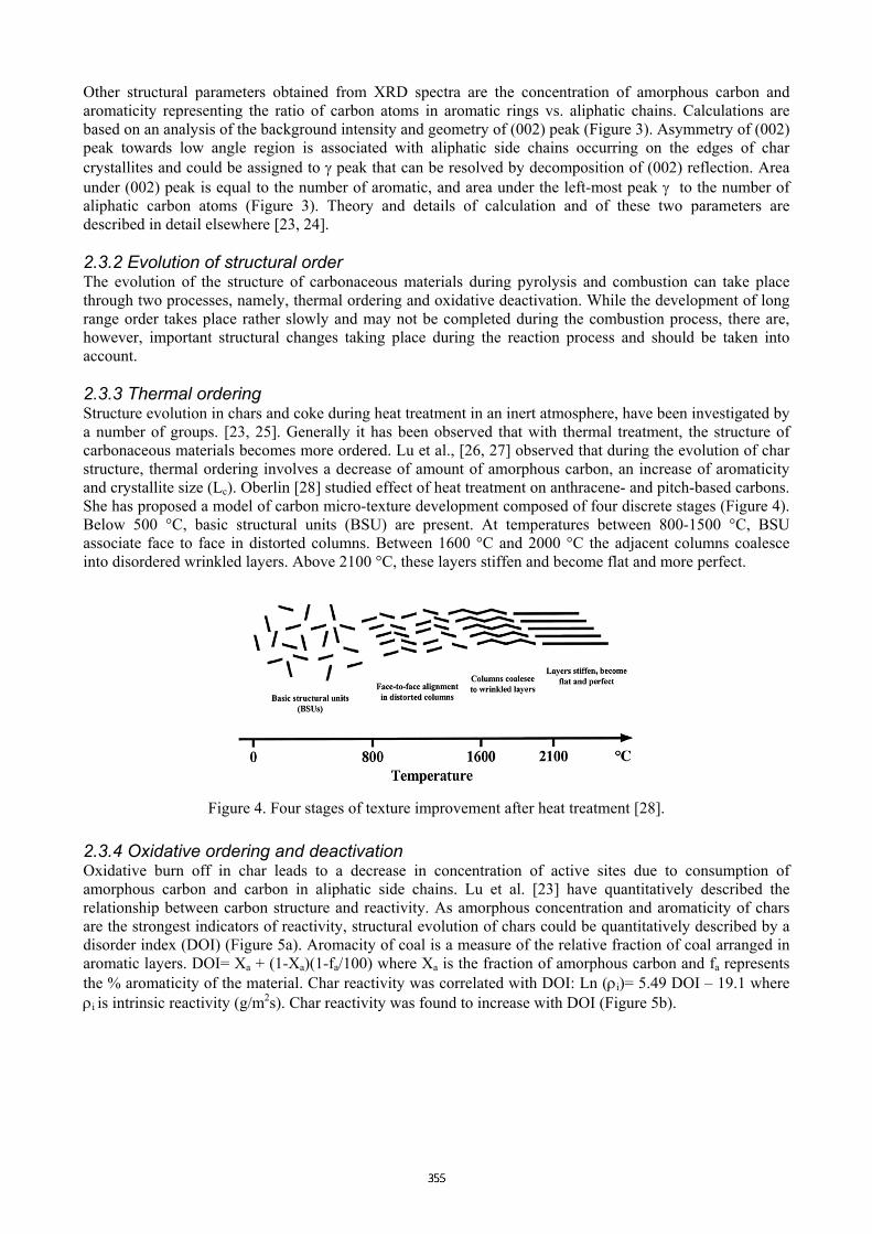
Other structural parameters obtained from XRD spectra are the concentration of amorphous carbon and aromaticity representing the ratio of carbon atoms in aromatic rings vs. aliphatic chains. Calculations are based on an analysis of the background intensity and geometry of (002) peak (Figure 3). Asymmetry of (002) peak towards low angle region is associated with aliphatic side chains occurring on the edges of char crystallites and could be assigned to γ peak that can be resolved by decomposition of (002) reflection. Area under (002) peak is equal to the number of aromatic, and area under the left-most peak γ to the number of aliphatic carbon atoms (Figure 3). Theory and details of calculation and of these two parameters are described in detail elsewhere [23, 24]. 2.3.2 Evolution of structural order The evolution of the structure of carbonaceous materials during pyrolysis and combustion can take place through two processes, namely, thermal ordering and oxidative deactivation. While the development of long range order takes place rather slowly and may not be completed during the combustion process, there are, however, important structural changes taking place during the reaction process and should be taken into account. 2.3.3 Thermal ordering Structure evolution in chars and coke during heat treatment in an inert atmosphere, have been investigated by a number of groups. [23, 25]. Generally it has been observed that with thermal treatment, the structure of carbonaceous materials becomes more ordered. Lu et al., [26, 27] observed that during the evolution of char structure, thermal ordering involves a decrease of amount of amorphous carbon, an increase of aromaticity and crystallite size (Lc). Oberlin [28] studied effect of heat treatment on anthracene- and pitch-based carbons. She has proposed a model of carbon micro-texture development composed of four discrete stages (Figure 4). Below 500 °C, basic structural units (BSU) are present. At temperatures between 800-1500 °C, BSU associate face to face in distorted columns. Between 1600 °C and 2000 °C the adjacent columns coalesce into disordered wrinkled layers. Above 2100 °C, these layers stiffen and become flat and more perfect.
Figure 4. Four stages of texture improvement after heat treatment [28]. 2.3.4 Oxidative ordering and deactivation Oxidative burn off in char leads to a decrease in concentration of active sites due to consumption of amorphous carbon and carbon in aliphatic side chains. Lu et al. [23] have quantitatively described the relationship between carbon structure and reactivity. As amorphous concentration and aromaticity of chars are the strongest indicators of reactivity, structural evolution of chars could be quantitatively described by a disorder index (DOI) (Figure 5a). Aromacity of coal is a measure of the relative fraction of coal arranged in aromatic layers. DOI= Xa + (1-Xa)(1-fa/100) where Xa is the fraction of amorphous carbon and fa represents the % aromaticity of the material. Char reactivity was correlated with DOI: Ln (ρi)= 5.49 DOI – 19.1 where ρi is intrinsic reactivity (g/m2s). Char reactivity was found to increase with DOI (Figure 5b).

Figure 5. (a) Char structural evolution during combustion, (b) Char-oxygen reactivity as a function of DOI,
measured at 673 K with O2 pressure of 0.3 atm. 3. REDUCTANT REACTIVITY The reductant can participate in various reduction reactions in a number of ways. Major reaction paths of relevance to the ferroalloy industry are listed below: • Gasification of reductant to form CO which can react in the furnace • Dissolution of carbon in the liquid metal • Reactions of dissolved carbon with slag as the metal descends to the hearth during the metal refining
process • Direct reduction reactions of solid carbon with slag These processes are inturn controlled by the reactivity of carbonaceous material towards oxidising gases, carbon dissolution into molten metal and slag/carbon interactions. Various factors affecting the performance of reductants are discussed below under these headings. 3.1 Reactivity towards oxidising gases Reactivity towards oxidizing gases including CO2, oxygen, air and steam play an important role in many metal-smelting processes. Numerous studies on coal and char reactivities have been reported using a variety of techniques (drop tube furnace, fixed bed reactor, wire mesh reactor), which generally do not reproduce conditions prevailing in the blast furnace/electric furnace etc., but enable one to study reactions under simple and well defined conditions. Studies on the effect of char structure, morphology, composition of parent coal on combustion/gasification kinetics have been reported in literature. Reactivity can be affected by both physical and chemical factors. These features are described in detail below. 3.1.1 Effect of physical characteristics Combustion of carbonaceous materials can be divided into three different regimes depending on the steps limiting the reaction rate. Combustion is controlled by chemical reaction at low temperatures (regime I), by pore diffusion at moderate temperatures (regime II) and by gas phase mass transfer at high temperatures [5]. Atomic structure plays an important role under regime I and II. However, reactivity under combustion regime II, where external or internal diffusion becomes rate limiting is also affected by particle size, porosity and other physical parameters. Reactions with oxidising gases change porous carbon matrix during combustion/gasification. The formation and evolution of pore structure by growth and coalescence leads to increasing or decreasing available surface areas, changes in pore structure/distribution, gas diffusion and reactivity. Pores can be described by size and morphology. Three pore-size ranges can be distinguished: micro-pores (<1 nm), mesopores (1-20 nm) and macro-pores (> 20 nm). Coal and chars have bimodal pore size distribution, with significant fraction of porosity corresponding to macro-pores and nearly all of the internal surface area in the micro- and mesopores. Macro-porosity of char is strongly affected by swelling and re-solidification behaviour of the parent coal [5]. Porous structure of coke is governed by the coking properties of coals, particularly by maximum fluidity and swelling number [29]. Char structure has been extensively studied due to its importance in combustion and gasification processes [5]. Under chemically controlled conditions (regime I), micropores play a substantial role in the reactivity of char particles. Two competing phenomena determine the evolution of pore structure, i.e., growth of
individual pores and coalescence of neighbouring pores [30]. Sorensen at al. [31] used image analysis technique to quantify and characterize pore size evolution in chars by SEM. According to their observations macroporosity of chars prepared from high volatile bituminous coals with different content of vitrinite and inertinite did not change during early stage of char burnout (0-30%). However, formation and growth of mesopores occurred. With increasing burnout the mesopore size distribution changed towards larger pore areas. At burnout interval above 30%, macroporosity increased due to coalescence of mesopores. 3.1.2 Chemical composition of ash Hermann [14] has evaluated the effect of chemical composition of coal ash on coke reactivity. While CaO and SO3 are gasification stimulating, Fe2O3 an Al2O3 have an intermediate effect, and P2O5, TiO2, MgO are gasification-inhibiting. Feng et al. [32] have observed that iron is a major catalyst during gasification of bituminous coal. HRTEM observations showed that well organised crystalline structures of carbon were found predominantly in the vicinity of the carbon/iron interface. Transformations of inorganic matter upon heat treatment include changes in chemical bonding, sintering, melting and vaporization as well as mutual interactions with organic matter. In addition to catalytic affect on reactivity of carbonaceous materials, mineral matter affects the thermal behaviour of char, and aggregation and particle size of mineral matter affect the fragmentation and mechanical stability of the carbonaceous material. Moreover, an increasing burnout mineral matter could have inhibiting effect by forming a barrier for oxidizing gases [33]. 3.2 Carbon dissolution into molten metal Carbon dissolution phenomenon in liquid metals has been extensively studied for liquid iron due to its importance in iron making processes. Carbon dissolution can be described by the first order kinetic equation
dCt/dt=K(Cs-Ct) (2) where Cs is saturation solubility, Ct is the instantaneous carbon concentration in the iron at time t, and K (sec-
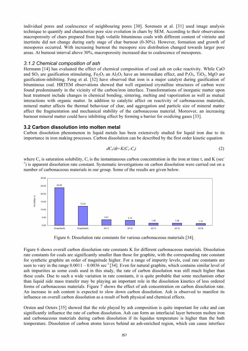
1) is apparent dissolution rate constant. Systematic investigations on carbon dissolution were carried out on a number of carbonaceous materials in our group. Some of the results are given below.
24.00
12.24
3.61 3.141.49 1.48 1.13
0.00
5.00
10.00
15.00
20.00
25.00
30.00
Graphite(S) Graphite(N) AC-Y AC-D AC-C AC-S AC-B
Kx10
00(s
-1)
Figure 6. Dissolution rate constants for various carbonaceous materials [34]. Figure 6 shows overall carbon dissolution rate constants K for different carbonaceous materials. Dissolution rate constants for coals are significantly smaller than those for graphite, with the corresponding rate constant for synthetic graphite an order of magnitude higher. For a range of impurity levels, coal rate constants are seen to vary in the range 0.0011 – 0.0036 sec-1 [34]. Even for natural graphite, which contains similar level of ash impurities as some coals used in this study, the rate of carbon dissolution was still much higher than these coals. Due to such a wide variation in rate constants, it is quite probable that some mechanism other than liquid side mass transfer may be playing an important role in the dissolution kinetics of less ordered forms of carbonaceous materials. Figure 7 shows the effect of ash concentration on carbon dissolution rate. An increase in ash content is expected to slow down carbon dissolution. Ash is observed to manifest its influence on overall carbon dissolution as a result of both physical and chemical effects. Orsten and Oeters [35] showed that the role played by ash composition is quite important for coke and can significantly influence the rate of carbon dissolution. Ash can form an interfacial layer between molten iron and carbonaceous materials during carbon dissolution if its liquidus temperature is higher than the bath temperature. Dissolution of carbon atoms leaves behind an ash-enriched region, which can cause interface

blockage and a reduction in the effective contact area for carbon dissolution. Addition of specific materials such as CaO or CaF2, to lower the melting temperature of ash below bath temperature, was found to significantly enhance the overall dissolution rate [36] as liquid ash gets flushed away by the streaming melt. Chemical composition and concentration of ash was also found to have a significant influence on the rate of carbon dissolution. Silica present in ash was found to take part in reduction reaction with dissolved carbon thereby affecting carbon concentration in the melt [37]. In order to identify factors other than ash, which could play an important role in carbon dissolution from coals into molten iron, we have also carried out a dissolution kinetics investigation on especially prepared coal-chars [16]. Starting from the same parent coal, several chars were prepared at temperatures ranging from 900°C to 1500°C. These chars and the parent coal are expected to have similar ash composition. In addition to aiding the removal of volatile matter, heat treatment during char preparation also leads to an improvement in the crystalline order and Lc values for coal-chars. Dissolution rate constants showed a significant improvement with increased char-making temperature (Figure 8), pointing towards the importance of atomic structure in dissolution kinetics.
0.00
5.00
10.00
15.00
20.00
25.00
30.00
0 5 10 15 20 Ash(wt%)
Kx10
00(s
-1)
Coal Graphite
Figure 7. Dependence of apparent carbon dissolution
constants of coal and graphiteon ash content [34].
Figure 8. Influence of temperature on the carbon dissolution from specially prepared coal-chars [ 38].
Carbon solubility in Fe-Si-C alloys varies with concentration of silicon. Carbon content at 1600°C drops from 5.4% C in silicon free alloy to 0.4 % at 22.4% Si, where metal coexists with graphite and SiC. Minimum C content is reached at 50% Si in alloy [39]. In general, addition of S, P, Si, Al, Ni and Co into molten iron decrease the solubility of graphite in liquid metal, while Mn and Cr give rise to a slight increase. Ferrochromium alloys contain 45-85 % Cr and various amounts of iron and carbon. Studies of slag-metal equilibrium in Fe-Cr-Si-C metal phase as typical for high-carbon ferrochromium smelting showed that carbon and silicon concentrations are inversely proportional. As the temperature increases (1500-1600 °C), the solubility of both silicon and carbon in the metal phase increases [40]. In addition to reactivity towards liquid iron, Dijs and Smith [41] studied reactivity of coal, char and coke towards liquid chromite. They concluded that reducing agents with low degree of graphitisation had higher liquid state reactivity. Addition of silica as a flux decreased reactivity. 3.3 Slag/carbon interactions Production of silicon and ferrosilicon is in principle defined as a slag free process [39]. However, formation of slag is inevitable in the production of other ferroalloys. Manganese and chromium are both reduced in the solid and the liquid state. Dissolution of MnO in the slag followed by reduction from the slag by solid carbon or carbon dissolved in liquid metal is considered as the major mechanism of MnO reduction [42]. Similarly, reduction of chromite in liquid slag by carbon and/or silica dissolved in Fe-Cr melts is important for the production of ferrochromium. In the electric arc furnace, coke and slag semi-active regions extend away from the electrodes. A slag (CaO-MnO-SiO2)/coke enriched layer was identified just below the electrode tips and “coke bed”. Reactions between carbon and liquid slag containing dissolved ore (chromium, manganese oxides) play a vital role in the reduction process.

0
20
40
60
80
100
120
140
1 10 100 1000 10000
time (s)
Cont
act a
ngle
(deg
rees
)
Char 1
Graphite S
Char 2
Graphite N
(a) (b) Figure 9. Variation of contact angle as a function of time for various carbonaceous materials with two slags
(a) Fe2O3 (31.52%) and SiO2 (20.7%) (b) Fe2O3 (0.24%) and SiO2 (36.3%) Slag/carbon interactions can be characterised in terms of carbon wetting and reaction kinetics during interaction of carbon with the slag phase. Wetting investigations on a number of carbonaceous materials were carried out different slags. Most materials, except for synthetic graphite, showed dynamic wetting with a silica rich slag. Dynamic wetting was not observed for iron oxide rich slags (Figure 9). These studies were supplemented with reaction kinetics investigations. Reduction of iron oxide was the predominant reaction of Fe2O3 rich slag with carbonaceous materials and silica reduction was inhibited and partial. Sahajwalla et. al [43] have investigated the influence of carbonaceous material and slag composition on the wettability and reaction kinetics at the graphite/slag interface. Two silica rich blast furnace slags with low levels of iron oxide and a respective basicity of 1.67(slag 1) and 1.22 (slag 2) respectively were used in this study. While synthetic graphite showed non-wetting behaviour with both slags, natural graphite showed dynamic wetting with slag 2, containing high levels of silica. This may be due to increased deposition of reaction products in the natural graphite/slag 2 system due to higher levels of silica present in natural graphite and slag 2. Reaction rates for silica reduction, as quantified by the number of moles of oxygen removed in off-gases, showed a large variation for different systems. Synthetic graphite had a small rate of oxygen removal with slag 1, but showed a significant increase with slag 2 for reaction rates in the initial stages of contact as well as in the extent of reactions. This is due to increased silica levels in the case of slag 2. For the high basicity slag, both the rate and extent of silica reduction show a strong dependence on the ash in the carbonaceous material. However for the low basicity slag, this dependence on the ash in the carbonaceous material is seen to be less strong. This may be understood on the basis of silica contribution from ash being lower for the low basicity slag compared to the corresponding value for the high basicity slag. These investigations clearly point towards the important role played by the slag composition as well as the carbonaceous material in wetting behaviour and overall reaction rates of silica reduction in low iron oxide bearing slags. Pei and Wijk [44] studied reduction kinetics of chromium oxides dissolved in CaO-SiO2-MgO-Al2O3 slag with graphite. The formation of carbide at slag/graphite interface improved the wetting behavior in the initial stage. At temperature ~1525 °C, thickness of the carbide layer increased as the reaction proceeded. At 1550 °C carbide layer was decarburised with the progress of the reaction and the formation of liquid alloy drops. At temperatures higher than 1575 °C reduction product was mainly a liquid Cr-C alloy.

4. CRITICAL REDUCTANT CHARACTERISTICS FOR FERROALLOYS PRODUCTION 4.1 Choice of reductant for electric arc furnace operations The most important property of a reducing agent used in submerged arc furnace is electrical resistivity of the material. This property depends on the type of material, processing conditions, material sizing, operating temperatures and pressures within the furnace mix bed etc. [45]. High burden resistivity is necessary for good overall heat distribution. It depends on resistivity of the reducing agent, volume fraction, carbon content and particle size. Higher resistivity is obtained for the burden where the particle size of the reductant is higher than those of other burden components [41]. Electrical resistivity of carbonaceous materials decreases with an increase in carbon content and increases with an increase of volatile matter and ash content. Other factors that affect electrical resistance are moisture content, particle size, ash distribution, microstructure and a degree of graphitisation [41]. Ordered or graphitic form of carbon is the most conductive form. Electrical resistivity is a structure sensitive parameter that reflects the internal structure. Therefore, electrical resistivity of carbonaceous material can be correlated with fraction of ordered carbon and reactivity [32]. Reactivity of reductants towards oxidation plays an important role in many metal-smelting processes. In general, reactivity decreases with the increase in the degree of graphitisation. In addition, the presence of carbon atoms in the amorphous phase or in aliphatic side chains also leads to an increase in reactivity. The combustion/gasification rate for different reduction materials can therefore be significantly different. As combustion proceeds, reactivity decreases due to the loss of volatile matter, enhanced thermal annealing and decreased concentration of active sites [46]. In addition to structural order, physical characteristics such as pore size distribution and surface area, and composition and concentration of ash impurities present in the carbonaceous material also play an important role. Primary electrical contact between the electrode and the charge is through a coke bed and the electrical properties of this zone are important as it determines the energy and the temperature distribution in the furnace [47]. 4.2 Choice of reductant for blast furnace operations Some ferroalloys e.g. ferromanganese are produced in electric submerged arc furnace as well as in blast furnace. Blast furnace production requires four times more coke as electric furnace and such production will be economic only where the cost of electric energy is higher compared to coke [47]. In the blast furnace, coke acts as the reducing agent, the source of energy and the physical support of the charge. Therefore the most important coke properties are low reactivity (CRI) and high strength (CSR). It is not obvious, what values of CRI and CSR are the best for coke used in electric furnace [6]. The coke bed size affects stability of the furnace operation and can be maintained using less reactive coke [48]. 4.3 Use of charcoal for ferroalloys production Charcoal has been used as a reducing agent in open submerged arc furnaces for a number of years especially in Brazil [45]. High resistivity of charcoal results in more efficient operation with respect to energy and electrode consumption. In production of silicon, low sulphur and ash content and high SiO reactivity of charcoal leads to high silicon recovery, good furnace operation and low costs. Paoul and See [49] studied SiO reactivity of different reduction agents. They concluded that SiO reactivity test also indicates strength of reduction material and formation of fines. Macedo at al. [45] compared properties of coke and charcoal used for production of silicon carbide. They summarized that main disadvantages of using charcoal are due to: hygroscopic properties (important especially in humid climates) low ignition temperature (120°C, which makes it difficult to dry), high degree of friability (during handling), variable carbon content (depends on type of wood, number of suppliers) and high volatiles content. This may be overcome by appropriately designed plant (higher capital costs). Such an example is silicon smelter in WA. Charcoal, with low ash content (0.4%) is a principal reductant and is produced from eucalyptus type wood. Timber waste (saw dust, chips, cuttings) is used to improve gas permeability of the burden and prevent charge crusting and decreases electrical conductivity [7].
4.4 Role played by the atomic structure Atomic structure is a key property of reduction materials determining their behaviour during smelting. Higher content of amorphous material is a critical for reactivity towards oxidizing gases. Reactivity towards liquid metal or dissolution in liquid metals is also dictated by the amount of ordered carbon or degree of graphitisation. Moreover, other important property electrical resitivity is also related to the fraction of ordered carbon. 5. REFERENCES [1] Riss A. and Khodorovsky, Y. “Production of ferroalloys”, Foreign Language Publishing House,
Moscow, 1967. [2] Fenton, M.D. “Ferroalloys”, www.minerals.er.usgs.gov/minerals/pubs/commodity/ferroalloys, 1998. [3] Raanes, O., Kolbeinsen, L. and Byberg, J.A. “Statistical analysis of properties for coals used in the
production of silicon rich alloys”, 8th International Ferroalloys Congress Proceedings INFACON, Beijing, China, China Science & Technology Press, 1998, pp. 116-120.
[4] Todd, S.J. and Hansen, H. “Nature and origin of coal and its petrographic characteristics”, Electric Furnace Conference Proceedings, vol. 53, Orlando, 1995, pp. 3-13.
[5] Smith, K.L., Smoot, L.D., Fletcher, H.T. and Pugmire, R.J. “The structure and reaction processes of coals”, The Plenum Chemical Engineering Series, Plenum Press, New York, USA, 1994.
[6] Pistorius, P.C. “Reductant selection in ferro-alloy production: The case for the importance of dissolution in metal”, J. S. Afr. Inst. Min. Metall., 200, 33-36.
[7] Spratt, D.M. and Brosnan, J.G. ”Successful production of silicon metal in western Australia”, Electric Furnace Conference Proceedings, vol. 48, Iron and Steel Society/AIME, New York, 1990, pp. 217-223.
[8] FAO.” Simple technologies for charcoal making” FAO Forestry Paper-41, 1987. [9] Emmerich, F.G. and Luengo, C.A. “Babassu charcoal: a sulfurless renewable thermo-reducing
feedstock for steelmaking”, Biomass and Bioenergy, 10, 1, 1996, pp. 41-44. [10] Areklett, I. and Nygaard, L.P. “The ferroalloys industry: Back to charcoal?” Greenhouse Issues, No 60,
2002. [11] Sampaio, R.S., Resende, M.E., Almeida, L.P., Junqueira, R.R. “The environmentally and
metallurgically clean ferroalloy producing system”, Electric Furnace Conference Proceedings, vol. 55, Iron and Steel Society/AIME, New York, 1997, pp. 281-287.
[12] Annual book of ASTM standards, section 5, “Petroleum products, lubricants and fossil fuels”, Vol. 5.05, “Gaseous fuels, Coal and Coke”, 1996.
[13] Hermann, W. “Coke reactivity and strength, Part 1: Coke reactivity-summary and outlook”, Cokemaking International, 1, 2002, pp. 1, 18, 20, 22, 24,26, 28-31.
[14] Farrell, K, Lu L, Sahajwalla, V., Harris, D., “Atomic scale structural features of some coals and chars”, 8th Australian Coal Science Conference, Sydney, Australia, 1998.
[15] Tuset, J.K. and Raanes, O. “Reactivity of reduction materials in the production of silicon, silicon-rich ferroalloys and silicon carbide”, Iron and Steel Society/AIME, Electric Furnace Conference, vol. 34, St. Louis, Mo., 1976, pp. 101-107.
[16] Raanes, O. and Gray, R.J. “Coal in the production of silicon rich ferroalloys”, INFACON 7, Trondheim, Norway, 1995, pp. 201-220.
[17] Goscinski, J.S., Patalsky, R.M. “CRS control - a coal producer’s point of view”, Ironmaking Conference Proceedings, vol. 49, Detroit, Michigan, USA, Iron and Steel Society, 1990, pp. 53-74.
[18] Green, T. and Kovak, J. “Coal structure”, R.A. Meyers (ed), Academic Press, 1982. [19] Krevelen, V. “ Coal: Typology-Physics-Chemistry-Constitution”. Elsevier, Amsterdam, 1993. [20] Hirch, P.B. ”Electron microscopy of thin crystals”, Butterworth, London, 1965. [21] Cullity, B.D. “Diffraction I: Direction of diffracted beams”, In: Elements of X-ray diffraction. 2nd ed.,
Addison-Wesley, 1978, pp. 81-106. [22] Shi, H., Reimers, J.N, Dahn, J.R. “Structure-refinement program for disordered carbons” J. Appl. Cryst.,
26, 1993, pp. 827-836. [23] Lu, L., Kong, C., Sahajwalla, V. and Harris, D. “Char structural ordering during pyrolysis and
combustion and its influence on char reactivity”, Fuel, 81, 2002. 1215-1225. [24] Ergun, S. “X-ray study of carbon”, In: Chemistry and physics of carbon. P.L.J. Walker (ed), New York,
USA, Marcer Dekker, 1967, pp. 211-288. [25] Kashiwaya, Y. and Ishii, K. “Kinetic analysis of coke gasification based on non-crystal/crystal ratio of
carbon”, ISIJ International, 31, No. 5, 1991, pp. 440-448.
[26] Lu, L., Sahajwalla, V. and Harris, D. “Coal char reactivity and structure - effects affecting PCI operation in blast furnace” Iron and Steel Society/AIME, 59th Ironmaking Conference Proceedings (USA), 2000, pp. 295-303.
[27] Lu, L., Sahajwalla, V., Kong, C. and Harris, D. “Quantitative X-ray diffraction analysis and its application to various coals”, Carbon, 39, 2001, 1821-1833.
[28] Oberlin, A. Carbon, 22, 1984, pp. 521. [29] Sato, H., Patrick, J.W. and Walker, A. “Effect of coal properties and porous structure on tensile strength
of metallurgical coke”, Fuel, 1998, 77, pp. 1203-1208. [30] Liu, G. Benyon, P., Benfell, K.E., Bryant, G.W, Tate, A.G., Boyd, R.K., Harris, D.J. and Wall, T.F.
“The porous structure of bituminous coal chars and its influence on combustion and gasification under chemically controlled conditions”, Fuel, 79, 2000, pp. 617–626.
[31] Sorensen, H.S., Rosenberg, P., Petersen, H.I and Sorensen, L.H. “Char porosity characterization by scanning electron microscopy an image analysis”, Fuel, 79, 2000, pp. 1379-1388.
[32] Feng, B., Bhatia, S.K. and Barry, J.C. “Structural ordering of coal char during heat treatment and its impact on reactivity”, Carbon, 40, 2002, 481-496.
[33] Smoot, L.D. and Smith, P.J. “Heterogeneous char reaction processes”, In Coal Combustion and Gasification. Plenum, New York, 1985, pp. 77-110.
[34] Wu, C., Wiblen, R. and Sahajwalla, V. “Influence of ash on mass transfer and interfacial reaction between natural graphite and liquid iron”, Metall. Mater Trans B, 31, 2000, pp. 1099-1104.
[35] Orsten, S. and Oeters, F.”Dissolution of carbon in liquid iron”, Proc. 5th Intern. Steel Congress, Washington, 1986, 143-155.
[36] Orsten, S. and Oeters, F. “Degassing of coal particles injecting into melt”, 188 Process Technology Conf. Proc., 1988, 31-42.
[37] McCarthy, F, Sahajwalla, V, Hart. J, and Saha-Chaudhury, N (2002) “Coke/iron Interfacial phenomena”, Proceedings of Mills Symposium, London, August 22-23, 2002, pp. 397 – 406
[38] Wiblen, R., Sahajwalla, V., Wu, C. “Influence of properties of carbonaceous materials on carbon dissolution into iron”, Iron and Steel Society/AIME, 60th Ironmaking Conference Proceedings, Baltimore, 2001, pp. 1005-1013.
[39] Schei, A., Tuset, J.K. and Tveit, H. “Production of high silicon ferroalloys”, TAPIR FORLAG, Trondheim, 1998.
[40] Akyuzulu, M. and Eric, R.H. “Slag-metal equilibrium in the smelting of high-carbon ferrochromium”, J. South Afr. Inst. Min. Metall., 92, 4, 1992, pp.101-110.
[41] Dijs, H.M., Smith, D.J. “Factors affecting the resistivity and reactivity of carbonaceous reducing agents for the electric-smelting industry”, J. S. Afr. Inst. Min. Metall., 1980, pp. 286-296.
[42] Rankin, W.J. and Van Deventer, J.S.J. “The kinetics of the reduction of manganous oxide by graphite”, J. S. Afr. Inst. Min. Metall., 1980, pp. 239-247.
[43] Sahajwalla V, Mehta A.S. and Khanna R, “Influence of Slag Composition and Ash Impurities on the Phenomena Occurring in the Carbon/Slag Interfacial Region”, submitted to Metall. Trans. B, 2003.
[44] Pei, W. and Wijk, O. “Mechanism of reduction of chromium oxide dissolved in the CaO-SiO2-MgO-Al2O3 slag by solid carbon”, Scandinavian J. Metall. (Denmark), 22, 1993, pp. 30-37.
[45] Macedo, C.J., d’Avila, E.A.O. and Brosnan, J.G. “Start up and operation of a closed calcium carbide furnace using charcoal as the reducing agent”, Electric Furnace Conference Proceedings, vol. 43, Iron and Steel Society/AIME, New York, 1985, pp. 255-262.
[46] Smith, I.W. “The combustion rates of coal chars: a review”, 19th International Symposium on Combustion. The Combustion Institute, Pittsburgh, 1982.
[47] Olsen, S.E. and Lindstad, T. “Ferromanganese production – process understanding”, Electric Furnace Conference Proceedings, Vol. 60, Iron and Steel Society/AIME, New York, 2002, pp. 205-216.
[48] De Waal, A., Barker, I.J., Rennie, M.S., Klopper, J. and Groeneveld, B.S. “Electrical factors affecting the economic optimization of submerged-arc furnaces”, INFACON 6. Proceedings of the 6th International Ferroalloys Congress, Cape Town, H. W. Glen (ed), Johannesburg. The South African Institute of Mining and Metallurgy, vol. 1, 1992, pp. 247-252.
[49] Paull, J.M. and See, J.B. “The interaction of silicon monoxide gas with carbonaceous reducing agents”, J. S. Afr. Inst. of Min. Metall., 79, 2, 1978, pp. 35-41.