Right lung has 3 lobes – superior, middle, inferior Left lung has 2 lobes – superior and inferior

INTERNATIONAL JOURNAL OF MICROWAVE AND OPTICAL TECHNOLOGY,
Reducing Side Lobes of Antenna Array by The Binomial
Method
H. Aziz1, M. Moubadir1, N. Amar Touhami1, A. Farkhsi1 , A. Tazon2
1Laboratoire of Information System and Telecommunications, Abdelmalek Essaàdi University, MAROC
2University of Cantabria, SPAIN E-mail: [email protected]
Abstract- This paper explores optimization and
synthesis of linear, which prints antennas arrays.
The developed synthesis bases on an optimization
binomial method. The objective of this paper is to
adapt the binomial method to reduce the side lobe
level. The application of this formalism gives
terrific results.
Index Terms- antenna array synthesis, antenna
printed, binomial method, optimization, radiation
pattern, side lobes.
I. INTRODUCTION
Today, the antennas have become an
indispensable tool for any radio link, for example
satellite, radar and radio. That is, they allow the
posting of fields of their metal supports and
radiation in space.
The development of new telecommunications
networks architectures, base stations providing a
dynamic reconfiguration and coverage satellite
tracking systems scrolling, require major
technological developments in these antennas. It
becomes imperative in the sense of having
antennas wide field and radiation opening to
allow significant pointing. Furthermore, it affect
without significantly increasing losses by
deformation of the radiation pattern. In addition
to that, Printed antennas are designed to meet the
requirements of this technological development,
and tended to the miniaturization of electronic
devices or telecommunications systems. With
their small size, performance, flexibility, they
make them particularly adaptable to mobile
equipment (satellite, airplane, boat). Which
means that, flexibility allows them to mix
imported form of surface (flat or formed). These
antennas have proven their effectiveness and
have tended to replace conventional antennas
permanently. Besides, their networking
association are the subject of extensive research,
and high performance to achieve specific
functions. Moreover, numerous types of
applications such as misalignment, electronic
scanning and rejection jammers output of
variable shapes or directions of radiation
patterns. In other terms, the operation takes place
by adjusting the parameters of number, spatial
position of the sources, amplitude and phase of
the supply characteristic, the elementary source.
In the field of printed antenna array, the synthesis
problem concerns more specialists, Which,
estimates the variations in amplitude phase and
the spatial distribution of radiating elements to
get fixed constraints radiation (reduction of side
lobes ). The purpose of the study is to find the
optimal combination of these parameters. So that,
the array meets the needs of the user in a precise
specification.
For synthesis of the radiation pattern of antenna
arrays, different overall analytical methods and
numerical optimization (Fourier, Woodward-
Lawson, relaxation, Newton, combined gradient,
genetic algorithm, simulated annealing algorithm,
Minmax, etc...) were developed and implemented
[1-7].
In this article, we present the binomial method
that will be applied to the synthesis of the
radiation pattern of the linear patch antenna
array.
40
IJMOT-2015-8-792 © 2016 IAMOT
VOL.11, NO.1, JANUARY 2016
INTERNATIONAL JOURNAL OF MICROWAVE AND OPTICAL TECHNOLOGY,
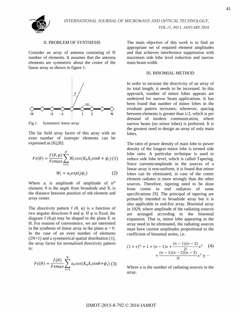
II. PROBLEM OF SYNTHESIS
Consider an array of antenna consisting of N
number of elements. It assumes that the antenna
elements are symmetric about the center of the
linear array as shown in figure 1.
Fig.1. Symmetric linear array
The far field array factor of this array with an
even number of isotropic elements can be
expressed as [6],[8]:
𝐹𝑠(𝜃) =𝑓(𝜃, 𝜑)
𝐹𝑠𝑚𝑎𝑥∑𝑊𝑖𝑐𝑜𝑠(𝐾0𝑋𝑖𝑠𝑖𝑛𝜃 + 𝜓𝑖)
𝑝
𝑖=1
𝑊𝑖 = 𝑎𝑖𝑒𝑥𝑝(𝑗𝜓𝑖)
Where ai is amplitude of amplitude of nth
element, θ is the angle from broadside and Xi is
the distance between position of nth element and
array center.
The directivity pattern f (θ, φ) is a function of
two angular directions θ and φ. If φ is fixed, the
diagram f (θ,φ) may be shaped in the plane E or
H. For reasons of convenience, we are interested
in the synthesis of linear array in the plane φ = 0.
In the case of an even number of elements
(2N+1) and a symmetrical spatial distribution [1],
the array factor for normalized directivity pattern
is:
𝐹𝑠(𝜃) =𝑓(𝜃)
𝐹𝑠𝑚𝑎𝑥∑𝑎𝑖𝑐𝑜𝑠(𝐾0𝑋𝑖𝑠𝑖𝑛𝜃+𝜓𝑖)
𝑁
𝑖=1
The main objective of this work is to find an
appropriate set of required element amplitudes
and that achieves interference suppression with
maximum side lobe level reduction and narrow
main beam width.
III. BINOMIAL METHOD
In order to increase the directivity of an array of
its total length, it needs to be increased. In this
approach, number of minor lobes appears are
undesired for narrow beam applications. It has
been found that number of minor lobes in the
resultant pattern increases; whenever, spacing
between elements is greater than λ/2, which is per
demand of modern communication, where
narrow beam (no minor lobes) is preferred. It is
the greatest need to design an array of only main
lobes.
The ratio of power density of main lobe to power
density of the longest minor lobe is termed side
lobe ratio. A particular technique is used to
reduce side lobe level, which is called Tapering.
Since currents/amplitude in the sources of a
linear array is non-uniform, it is found that minor
lobes can be eliminated, in case of the center
element radiates is more strongly than the other
sources. Therefore, tapering need to be done
from center to end radiators of same
specifications [9]. The principal of tapering are
primarily intended to broadside array but it is
also applicable to end-fire array. Binomial array
in 1929, where amplitude of the radiating sources
are arranged according to the binomial
expansion. That is, minor lobe appearing in the
array need to be eliminated, the radiating sources
must have current amplitudes proportional to the
coefficient of binomial series, i.e.
(1 + 𝑥)𝑛 = 1 + (𝑛 − 1)𝑥 +(𝑛 − 1)(𝑛 − 2)
2!𝑥2
+(𝑛 − 1)(𝑛 − 2)(𝑛 − 3)
3!𝑥3 ±⋯
Where n is the number of radiating sources in the
array.
(1)
(3)
(4)
(2)
41
IJMOT-2015-8-792 © 2016 IAMOT
VOL.11, NO.1, JANUARY 2016

INTERNATIONAL JOURNAL OF MICROWAVE AND OPTICAL TECHNOLOGY,
For an array of total length (nλ/2), the relative
current in the nth element form the one end is
given by
(1 + 𝑥)𝑛 =𝑛!
𝑟! (𝑛− 𝑟)!
Where r=0, 1, 2, 3.., and the above relation is
equivalent to what is known as Pascal’s triangle.
IV. MICROSTRIP PATCH ANTENNA
RESONATING AT 5.86GHz
The proposed microstrip patch antenna is shown
in Figure2. For improved adaptation, two slots
and two cuts are introduced on the patch. In this
design the substrate is Arlon45. The substrate
height is 1.6mm, the dielectric constant is 3.2 and
the loss tangent is 0.018. The dimensions of our
antenna are optimized by using CST Microwave
Studio tool.
Fig.2. Top view of our patch antenna resonating at
5.86GHz, (A = 0.2 mm, B = 2.75mm,C = 0.69 mm, D
= 5 mm, E = 7.95 mm, F =1.02mm, G=H = 3.1 mm
and I = 17.66mm).
Fig.3. Simulated return loss of the patch antenna
resonating at 5.86GHz.
Figure 3 shows that the antenna has a good
adaptation (around -50dB) at the resonant
frequency (5.86GHz).
V. ANTENNA ARRAY: UNIFORM
DISTRIBUTION
On the basis of this analysis, we have chosen as
optimum separation distance 0.7 λ0. Because for
this the antenna array has good performance, the
side lobes and the coupling between the antennas
have been reduced [10].
P1 P2 P3 P4 P5
Fig.4. Linear microstrip array of five elements.
Fig.5. Scattering parameters of array antenna
The mutual coupling is due to the simultaneous
effects of radiation in free space and propagation
of the surface waves. The important factor should
be considered in the calculation of network
characteristics. Figure 5 shows that the coupling
between the network elements is reduced.
(5)
42
IJMOT-2015-8-792 © 2016 IAMOT
VOL.11, NO.1, JANUARY 2016

INTERNATIONAL JOURNAL OF MICROWAVE AND OPTICAL TECHNOLOGY,
Fig.6. Radiation pattern of symmetric antenna array
using uniform distribution (P1=P2=P3=P4=P5=1A).
In Figure 6, we can see the radiation pattern of
symmetrical array by using uniform distribution.
The side lobe level is lower than -12.9dB, which
indicates the existence of parasitic radiation. That
will influence the reliability of these antennas. As
a result, to reduce the side lobe level, in next
section we use the binomial method.
VI. ANTENNA ARRAY: BINOMIAL
METHOD
The side lobe level in uniform distribution may
pick up interfering signals, and increase the noise
level in the receiver. One possible solution is to
change the power distribution networks of array
antenna by using binomial approach.
Figure 7 shows the radiation pattern of antenna
array with or without binomial distribution. We
can see that the side lobe reduction is about
-28.3dB.
Fig.7. Radiation pattern of symmetric antenna array
(for binomial method P1=P5=0.7A, P2=P4=1.5A,
P3=2A).
Figure 8 illustrate the comparison between
theoretical and simulated radiation pattern of
antenna by using binomial method. That is, we
can see the agreement of both results.
Fig.8 Comparison between binomial method
simulated and theoretical.
VII. CONCLUSION
The microstrip planar antenna arrays with
binomial technique concept have been studied in
this paper with the objective to reduce the side
lobe level. Also the comparison results of
uniform and binomial distribution show that the
side lobe reduction is about -28.3dB. The
theoretical radiation patterns show the agreement
with simulations. That is, the side lobe level was
suppressed.
ACKNOWLEDGMENT
The authors would like to thank the engineering
department of communications and University of
Cantabria.
REFERENCES
[1] F. T. Bendimerad, E. Cambiaggio, A. Papiernik,
“Méthode non linéaire de synthèse de réseaux
d’antennes non périodiques: Application aux
antennes microrubans”, Annales des
télécommunications, 43, n° 5-6, 1988, pp- 265-
275.
[2] Damiano, “Contribution à l’étude des antennes
microrubans multicouches à éléments superposes
-90° -60° -30° 00° 30° 60° 90°-50
-40
-30
-20
-10
0
10
Theta
Radia
tion in (
dB
)
-90° -60° -30° 00° 30° 60° 90°-50
-40
-30
-20
-10
0
10
Theta
Ra
dia
tio
n in
(d
B)
Binomial Method Simulated
Uniform Distribution
-90° -60° -30° 00° 30° 60° 90°-50
-40
-30
-20
-10
0
10
Theta
Radia
tion in (
dB
)
Binomial Method Simulated
Binomial Method Theoretical
43
IJMOT-2015-8-792 © 2016 IAMOT
VOL.11, NO.1, JANUARY 2016

INTERNATIONAL JOURNAL OF MICROWAVE AND OPTICAL TECHNOLOGY,
ou décalés”, Thèse de Docteur es-sciences,
Université de Nice-Sophia Antipolis, Janvier
1989.
[3] G.K. Mahanti, N. Pathak and P. Mahanti,
“Synthesis of Thinned Linear Antenna Arrays
with Fixed Sidelobe Level Using Real-Coded
Genetic Algorithm”, Progress In
Electromagnetics Research, PIER, Vol 75, pp-
319–328, 2007.
[4] M. Siva Priya Mala, K.Ch. Sri Kavya, Dr.
Habibulla Khan, N. Srinija and K. Nagendra
Babu, “Optimization of Linear Array Antennas by
the Gradient Method”, International Journal of
Modern Engineering Research, Vol.1, Issue.2, pp-
637-641.
[5] M. Bousahla, M. Abri, F. T. Bendimerad and N.
Boukli-hacene, “Synthesis of Circular Arrays with
Simulated Annealing Optimization Algorithm”,
International Journal of Electronics and
Communication Engineering, Vol 2, Number 3,
pp- 147–159, 2009.
[6] L. Merad, F.T. Bendimerad, S.M. Meriah, S.A.
Djennas, “Neural Networks forsynthesis and
optimization of antennas arrays”, Radio
engineering Journal, Vol 16, N°1, April 2007.
[7] F. Harrou, B. Bouyeddou, S. A. Djennas, L.
Merad, “Synthèse et Optimisation de Réseaux
d'Antennes Imprimées Linéaires par la Méthode
du Minimax”, 5th International Conference:
Sciences of Electronic, Technologies of
Information and Telecommunications, Tunisia,
March 22-26, 2009.
[8] R. Ghayoula. “Contribution à l’Optimisation de la
Synthèse des Antennes Intelligentes par les
Réseaux de Neurones”, Thèse. La faculté des
sciences de Tunis, 27 décembre 2008.
[9] R. L. Yadava, “Antenna and Wave Propagation”,
Eastern Economy Edition, pp- 147-148, 2011.
[10] H. Aziz, N. Amar Touhami, A. Farkhsi, M.
Boussouis, “Influence de Variation de la Distance
de Separation Entre les Antennes Patch”, Congres
Mediterraneen des Telecommunications et
Exposition, Mohammedia – Maroc, 22-23-24 Mai
2014.
44
IJMOT-2015-8-792 © 2016 IAMOT
VOL.11, NO.1, JANUARY 2016