Red Comercial Nacional MANUAL DE … · [email protected] BARCELONA C/ Sant Ferrán, 27. ... VIGO...
48
MANUAL DE INSTRUCCIONES MANUAL OF INSTRUCTIONS BEDIENUNGSANLEITUNG MANUEL D’INSTRUCTION MANUALE DI ISTRUZIONI MANUAL DE INSTRUÇÕES
Transcript of Red Comercial Nacional MANUAL DE … · [email protected] BARCELONA C/ Sant Ferrán, 27. ... VIGO...
����
�������
�����
�� ���
������
��������
�����
������
������
���������
����� �
�������� �������
���� �����
������������
��������
��� �
���������
������
����������������
����������
����������
������
� ������
�������
������
������
����
����
�������
�������
�������
�������
�������
������
������
����������
������
��������������
��������
�������
��������
�� �����
��� ���
����������
������
����
����
��������
����
�������
�������������
�������
��������
� �����
Rúa B. de Conxo, 17
C.P. 15706 SANTIAGO DE COMPOSTELA
Tel.: 981 52 22 00 Fax: 981 52 22 62
[email protected] www.televes.com
RReedd CCoommeerrcciiaall NNaacciioonnaall
���� !"�#��$%��!"�#�&
���''()*)+(
���������������
A CORUÑAGregorio Hernández 8. - C.P. 15011 Tfnos: 981 27 47 31 /981 27 22 10Fax: 981 27 16 [email protected]
ALMERÍACampogrís 9. - C.P. 04008Tfno.: 950 23 14 43Fax: 950 23 14 [email protected]
BADAJOZC/ Jacobo Rodríguez Pereira,nº11-Oficina. - C.P. 06010Tfno.: 924 20 74 83 Móvil: 670 70 21 93Fax: 924 20 01 [email protected]
BARCELONAC/ Sant Ferrán, 27.Cornellá. - C.P. 08940 Tfnos.:93 377 08 62 /93 474 29 50Fax: 93 474 50 [email protected]
BILBAOIberre Kalea, módulo 16,pabellón 15-BSangroniz-Sondika - C.P. 48150Tfnos.:94 471 12 02 /94 471 24 78Fax: 94 471 14 [email protected]
BURGOSC/ Real, s/n, San Adrián de JuarrosC.P. 09188Tfno.: 947 56 04 58Móvil: 670 73 75 [email protected]
GIJÓNC/ Japón, 14. - C.P. 33210Tfnos.:985 15 25 50 /985 15 29 67Fax: 985 14 63 [email protected]
JAÉNHermanos Pinzón, 8-bajo.C.P. 23007Tfnos.:953 29 50 40 /953 29 52 11Móvil: 636 984489 Fax: 953 29 52 [email protected]
LAS PALMASGral. Mas de Gaminde 26.C.P. 35006Tfnos.:928 23 11 22 /928 23 12 42Fax: 928 23 13 [email protected]
LOGROÑOSan Prudencio 19. bajo. - C.P. 26004 Tfno.: 941 23 35 24Fax: 941 25 50 [email protected]
MADRIDPaseo de los Pontones 11.C.P. 28005Tfnos.:91 474 52 21 /91 474 52 22Fax: 91 474 54 [email protected]
MÁLAGAPol. Ind. Alameda 2.C/ La Boheme, 55. - C.P. 29006Tfno.: 952 03 82 26Fax: 952 03 82 22 [email protected]
MURCIAPolígono ConverC/ Rio Pliego 22. - C.P. 30010Tfnos.:968 26 31 44 /968 26 31 77Fax: 968 25 25 [email protected]
PAMPLONAAvd. Sancho el Fuerte 5. - C.P. 31007Tfno.: 948 27 35 10Fax: 948 17 41 [email protected]
SEVILLAPol. Ind. Store - C/ A-6. Nave 5.C.P. 41008Tfnos.:95 443 64 50 /95 443 58 00 Fax: 95 443 96 [email protected]
PALMA DE MALLORCAFerrer de Pallares 45. bajo D.C.P. 07007Tfno.: 971 24 70 02Fax: 971 24 53 [email protected]
TENERIFEAvd. El Paso, 25. - C.P. 38108Los Majuelos- La LagunaTfnos.:922 31 13 14 /922 31 13 16Fax: 922 31 13 [email protected]
VALENCIAPlaza Jordi San Jordi s/n.C.P. 46022 Tfnos.:96 337 12 01 /96 337 12 72 Fax: 96 337 06 [email protected]
VIGOEscultor Gregorio Fernández, 5.C.P. 36204Tfnos.:986 42 33 87 /986 42 40 44Fax: 986 42 37 [email protected]
VALLADOLIDC/ Arrecife 12. - C.P. 47008Tfno.: 983 22 36 66Fax: 983 22 36 [email protected]
ZARAGOZAC/ Monasterio de Alahón 1-3.C.P. 50002Tfno.: 976 41 12 73Fax: 976 59 86 [email protected]
MANUAL DE INSTRUCCIONESMANUAL OF INSTRUCTIONS
BEDIENUNGSANLE ITUNG
MANUEL D ’ INSTRUCTIONMANUALE D I ISTRUZ IONIMANUAL DE INSTRUÇÕES
TELEVES ITALIA S.r.l.S.op.Viale Liguria 24 20068 Peschiera Borromeo (MI)ItaliaTel.: (+39)-0251650604 (RA)Fax: (+39)[email protected]
TELEVES MIDDLE EAST FZEP.O. Box 17199JEBEL ALI FREE ZONE DUBAI, UNITED ARAB EMIRATESTel.: 9714 88 343 44Fax: 9714 88 346 44 [email protected]
TELEVES UNITED KINGDOM LTDUnit 11 Hill Street, Industrial StateCWMBRAN, GWENT NP44 7PG. (United Kingdom)Tel.: 44 01 633 87 58 21Fax: 44 01 633 86 63 [email protected]
TELEVES FRANCE S.A.R.L.1 Rue Louis de BroglieParc d'Activités de l'Esplanade77400 St Thibault des VignesFRANCETél.:+33 (0)1 60 35 92 10 Fax: +33 (0)1 60 35 90 [email protected]
TELEVES ELECTRONICA PORTUGUESA
RReedd CCoommeerrcciiaall IInntteerrnnaacciioonnaall
MAIA - OPORTOVia . Dr Francisco Sa Carneiro. Lote 17. ZONA Ind. MAIA 1.Sector-X MAIA. C.P. 4470 BARCATel.: 351 22 9418313Fax: 351 22 9488719/[email protected]. 1000 Rua Augusto Gil 21-A.Tel.: 351 21 7932537Fax: 351 21 [email protected]

ÍNDICE Pag
1.- Requisitos . . . . . . . . . . . . . . . . . . . . . . . . . . . . . . . . . . . . . 4
2.- Instalación . . . . . . . . . . . . . . . . . . . . . . . . . . . . . . . . . . . . . 5
3.- Control remoto de una cabecera . . . . . . . . . . . . . . . . . . 5
4.- Control local de una cabecera . . . . . . . . . . . . . . . . . . . . . 5
5.- Control local de un único dispositivo . . . . . . . . . . . . . . . 6
5.1.- Identificar un dispositivo . . . . . . . . . . . . . . . . . . . . . . . 7
5.2.- Configuración y ajuste de una AVANT 5 . . . . . . . . . .mediante el software de Control de Cabeceras . . . . 8
5.2.1.- Realizar una configuración y ajuste de la unidad 11
5.2.2.- Resultado de ajuste . . . . . . . . . . . . . . . . . . . . . . . 13
5.3.- Configuración y ajuste de la AVANT 5 . . . . . . . . . . . .sin necesidad de estar en la instalación . . . . . . . . . . 15
3
CDCM a n u a l d e l U s u a r i o
ES
PA
ÑO
L
4
CDC M a n u a l d e l U s u a r i o
1.- Requisitos
EQUIPAMIENTO MÍNIMO:
PC con procesador Pentium II
64 Mb RAM
CD-ROM 2x
20 MB libres en el disco duro.
Windows 98/NT/2000/XP.
EQUIPAMIENTO RECOMENDADO:
PC con procesador Pentium IV o superior
256 Mb RAM
CD-ROM 12x
22 MB libres en el disco duro.
Windows 2000/XP.
5
CDCM a n u a l d e l U s u a r i o
ES
PA
ÑO
L
2.- Instalación
El programa Gestión de Cabecera se suministra en un CD-ROM paraWindows. Para instalar el programa se introduce el CD-ROM en el lec-tor y se siguen las instrucciones que van apareciendo en la pantalla. Sino se ejecutara el programa de autoarranque, porque estuviera desac-tivada esta opción, se deben seguir los siguientes pasos:
Hacer doble "clic" en el icono "Mi PC" del escritorio de Windows.En la ventana "Mi PC", hacer doble "clic" en el icono de la unidadlectora de CD-ROM (usualmente D:\)En la ventana de la unidad CD-ROM, hacer doble "clic" en elicono "setup.exe".
Seguir las instrucciones que aparecen en la pantalla.
Finalizada la instalación, el programa Control de Cabecera arranca
tras hacer doble "clic" en el icono correspondiente .
3.- Control remoto de una cabecera
Encontrará información detallada sobre este tema tanto en el manualdel módulo CDC, como en la propia ayuda del Software de Control deCabeceras.
4.- Control local de una cabecera
Antes de iniciar una sesión en modo local asegúrese que el puertoseleccionado para la comunicación es el correcto, por medio del menú"Configuración\Comunicaciones". El cable de comunicaciones por unaparte debe conectarse al puerto serie del PC y por el otro al conectormarcado como PRGM del dispositivo CDC.
1.- Deje sin selección la casilla Utilizar módem en el menú deControl de sesión.
2.- Cargue una cabecera o cree una nueva.
6
CDC M a n u a l d e l U s u a r i o
3.- Haga clic en el botón Iniciar Sesión.4.- Introduzca la Password. (La primera vez que instale un dispositi-
vo CDC (hardware) la password será Televes1)
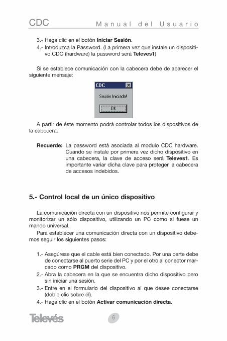
Si se establece comunicación con la cabecera debe de aparecer elsiguiente mensaje:
A partir de éste momento podrá controlar todos los dispositivos dela cabecera.
Recuerde: La password está asociada al modulo CDC hardware.Cuando se instale por primera vez dicho dispositivo enuna cabecera, la clave de acceso será Televes1. Esimportante variar dicha clave para proteger la cabecerade accesos indebidos.
5.- Control local de un único dispositivo
La comunicación directa con un dispositivo nos permite configurar ymonitorizar un sólo dispositivo, utilizando un PC como si fuese unmando universal.
Para establecer una comunicación directa con un dispositivo debe-mos seguir los siguientes pasos:
1.- Asegúrese que el cable está bien conectado. Por una parte debede conectarse al puerto serie del PC y por el otro al conector mar-cado como PRGM del dispositivo.
2.- Abra la cabecera en la que se encuentra dicho dispositivo perosin iniciar una sesión.
3.- Entre en el formulario del dispositivo al que desee conectarse(doble clic sobre él).
4.- Haga clic en el botón Activar comunicación directa.

7
CDCM a n u a l d e l U s u a r i o
ES
PA
ÑO
L
NOTA: Sólo podrá establecer comunicación directa con un disposi-tivo cuando no exista ninguna sesión abierta. Además el dis-positivo dibujado debe tener la misma dirección que el dispo-sitivo físico.
5.1.- Identificar un dispositivo
Esta herramienta permite obtener los datos principales de un dispo-sitivo, como son su dirección, referencia y descripción. Además permi-te dibujar automáticamente el dispositivo en una hoja en blanco o aña-dirlo en una cabecera ya dibujada.
Para identificar un dispositivo, conecte el cable desde el puerto seriedirectamente al dispositivo que desea identificar, entre enHerramientas -> Identificar dispositivo (o bien haga clic sobre elbotón del menú principal Identificar dispositivo) y haga "clic" en elbotón Identificar.
Como ya se ha comentado, una vez identificado el dispositivo puedeañadirlo a una cabecera nueva o añadirlo a una cabecera abierta previa-mente.
8
CDC M a n u a l d e l U s u a r i o
El menú Herramientas -> Identificar dispositivo sólo está disponi-ble cuando no hay abierta ninguna sesión.
5.2.- Configuración y ajuste de una AVANT 5 mediante el softwarede Control de Cabeceras.
A continuación se muestra como configurar y ajustar una centralAVANT 5 utilizando el software de Gestión de Cabeceras. Este softwarede control además de proporcionarnos la capacidad de controlar remo-tamente este tipo de centrales, simplifica su manejo y configuración gra-cias a un intuitivo y detallado interfaz de usuario sobre PC que permiteestablecer de forma inmediata todos los parámetros de configuraciónnecesarios e identificar el estado de ajuste y funcionamiento de la uni-dad.
Se supondrá que el PC que soporta el programa de Control deCabeceras está conectado directamente a una Avant 5 (ver apartado"Control local de un único dispositivo -> Comunicación directa"). Elmanejo es idéntico para el caso de una conexión remota o local a tra-vés de un módulo CDC, en todos ellos el PC nos permite configurar lacentral como si se tratase de un mando universal.
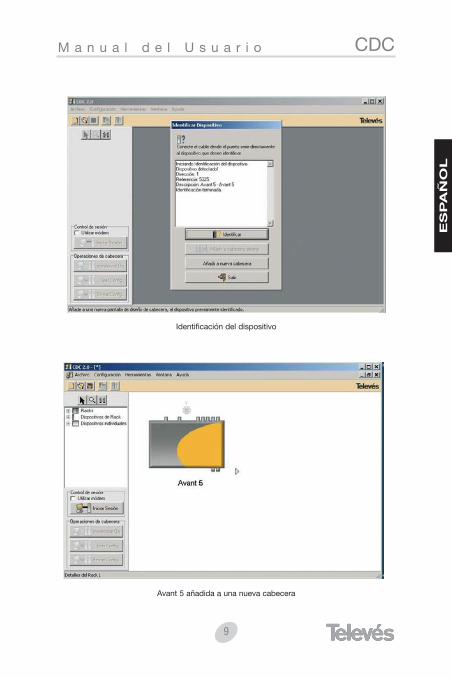
Una vez se ha conectado convenientemente el PC a la Avant median-te el cable de comunicaciones se arranca el programa de Control deCabeceras. En el modo "Comunicación directa" la herramienta"Identificar dispositivo" es un modo muy conveniente de generar deforma inmediata una cabecera y acceder al dispositivo en cuestión, paraello deberá pulsar en el menú Herramientas y en la opción "Identificardispositivo", lo que muestra la siguiente pantalla:
9
CDCM a n u a l d e l U s u a r i o
ES
PA
ÑO
L
Identificación del dispositivo
Avant 5 añadida a una nueva cabecera
10
CDC M a n u a l d e l U s u a r i o
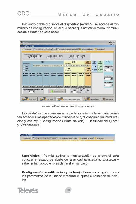
Haciendo doble clic sobre el dispositivo (Avant 5), se accede al for-mulario de configuración, en el que habrá que activar el modo "comuni-cación directa" en este caso:
Ventana de Configuración (modificación y lectura)
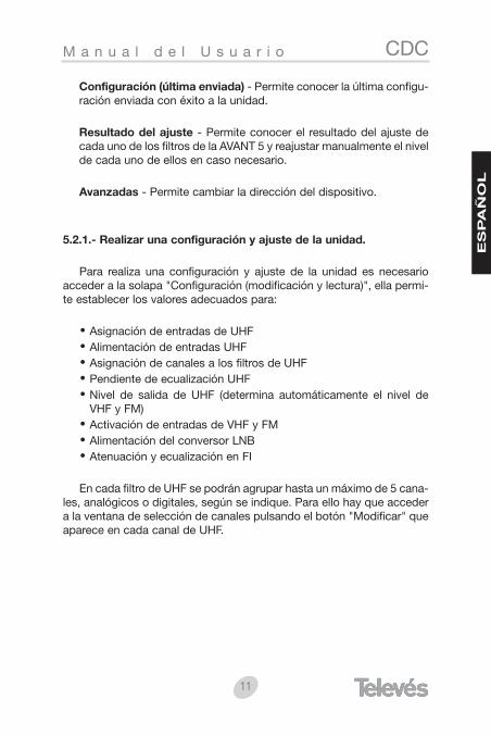
Las pestañas que aparecen en la parte superior de la ventana permi-ten acceder a los apartados de "Supervisión", "Configuración (modifica-ción y lectura)", "Configuración (última enviada)", "Resultado del ajuste"y "Avanzadas":
Supervisión - Permite activar la monitorización de la central paraconocer el estado de ajuste de la unidad (ajustada/no ajustada) ysaber si ha habido errores de nivel en su caso.
Configuración (modificación y lectura) - Permite configurar todoslos parámetros de la unidad y realizar el ajuste automático de nive-les.
11
CDCM a n u a l d e l U s u a r i o
ES
PA
ÑO
L
Configuración (última enviada) - Permite conocer la última configu-ración enviada con éxito a la unidad.
Resultado del ajuste - Permite conocer el resultado del ajuste decada uno de los filtros de la AVANT 5 y reajustar manualmente el nivelde cada uno de ellos en caso necesario.
Avanzadas - Permite cambiar la dirección del dispositivo.
5.2.1.- Realizar una configuración y ajuste de la unidad.
Para realiza una configuración y ajuste de la unidad es necesarioacceder a la solapa "Configuración (modificación y lectura)", ella permi-te establecer los valores adecuados para:
Asignación de entradas de UHFAlimentación de entradas UHFAsignación de canales a los filtros de UHFPendiente de ecualización UHFNivel de salida de UHF (determina automáticamente el nivel deVHF y FM)Activación de entradas de VHF y FMAlimentación del conversor LNBAtenuación y ecualización en FI
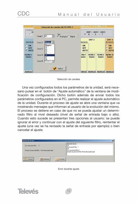
En cada filtro de UHF se podrán agrupar hasta un máximo de 5 cana-les, analógicos o digitales, según se indique. Para ello hay que accedera la ventana de selección de canales pulsando el botón "Modificar" queaparece en cada canal de UHF.
12
CDC M a n u a l d e l U s u a r i o
Selección de canales
Una vez configurados todos los parámetros de la unidad, será nece-sario pulsar en el botón de "Ajuste automático" de la ventana de modi-ficación de configuración. Dicho botón además de enviar todos losparámetros configurados en el PC, permite realizar el ajuste automáticode la unidad. Durante el proceso de ajuste se abre una ventana que vamostrando mensajes que informan al usuario de la evolución del mismo.El proceso se detiene en caso de que no se pueda ajustar un determi-nado filtro al nivel deseado (nivel de señal de entrada bajo o alto).Cuando esto sucede se presentan tres opciones al usuario: se puedeignorar el error y continuar con el ajuste del siguiente filtro, reintentar elajuste (una vez se ha revisado la señal de entrada por ejemplo) o biencancelar el ajuste.
Error durante ajuste

13
CDCM a n u a l d e l U s u a r i o
ES
PA
ÑO
L
5.2.2.- Resultado de ajuste.
Una vez terminado el proceso de ajuste automático aparece en pan-talla la ventana de resultado. En ella se muestra una representación grá-fica del resultado del ajuste automático de la unidad, informando al ins-talador de los posibles errores de nivel en los filtros, de la distribuciónde canales por filtro y de la pendiente de ecualización. Asimismo permi-te ajustar manualmente y de forma individual cada uno de los filtros enun rango de ± 9 dB para realizar los ajustes finos que puedan ser nece-sarios en cada instalación particular.
Resultado del ajuste
Los filtros que hayan podido ser ajustados al nivel deseado aparecenrepresentados en verde (ajuste correcto), mientras que aquellos en losque haya habido un error de nivel bajo o de nivel alto aparecerán repre-sentados en rojo.
14
CDC M a n u a l d e l U s u a r i o
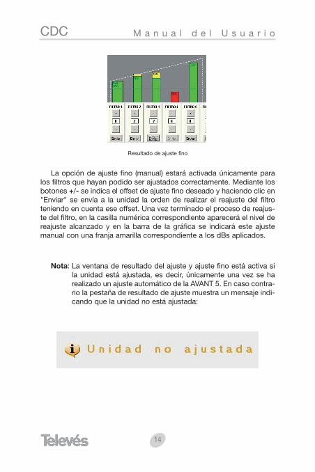
Resultado de ajuste fino
La opción de ajuste fino (manual) estará activada únicamente paralos filtros que hayan podido ser ajustados correctamente. Mediante losbotones +/- se indica el offset de ajuste fino deseado y haciendo clic en"Enviar" se envía a la unidad la orden de realizar el reajuste del filtroteniendo en cuenta ese offset. Una vez terminado el proceso de reajus-te del filtro, en la casilla numérica correspondiente aparecerá el nivel dereajuste alcanzado y en la barra de la gráfica se indicará este ajustemanual con una franja amarilla correspondiente a los dBs aplicados.
Nota: La ventana de resultado del ajuste y ajuste fino está activa sila unidad está ajustada, es decir, únicamente una vez se harealizado un ajuste automático de la AVANT 5. En caso contra-rio la pestaña de resultado de ajuste muestra un mensaje indi-cando que la unidad no está ajustada:
15
CDCM a n u a l d e l U s u a r i o
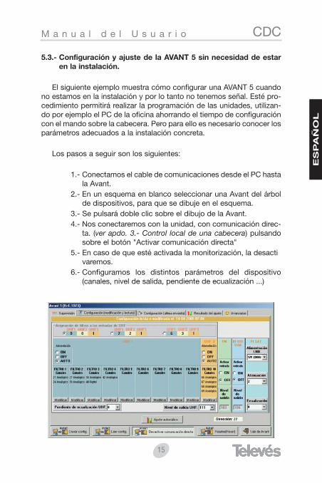
5.3.- Configuración y ajuste de la AVANT 5 sin necesidad de estaren la instalación.
El siguiente ejemplo muestra cómo configurar una AVANT 5 cuandono estamos en la instalación y por lo tanto no tenemos señal. Esté pro-cedimiento permitirá realizar la programación de las unidades, utilizan-do por ejemplo el PC de la oficina ahorrando el tiempo de configuracióncon el mando sobre la cabecera. Pero para ello es necesario conocer losparámetros adecuados a la instalación concreta.
Los pasos a seguir son los siguientes:
1.- Conectamos el cable de comunicaciones desde el PC hastala Avant.
2.- En un esquema en blanco seleccionar una Avant del árbolde dispositivos, para que se dibuje en el esquema.
3.- Se pulsará doble clic sobre el dibujo de la Avant.4.- Nos conectaremos con la unidad, con comunicación direc-
ta. (ver apdo. 3.- Control local de una cabecera) pulsandosobre el botón "Activar comunicación directa"
5.- En caso de que esté activada la monitorización, la desacti varemos.
6.- Configuramos los distintos parámetros del dispositivo(canales, nivel de salida, pendiente de ecualización ...)
ES
PA
ÑO
L
16
CDC M a n u a l d e l U s u a r i o
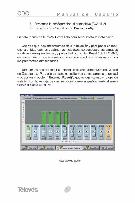
7.- Enviamos la configuración al dispositivo (AVANT 5)8.- Hacemos "clic" en el botón Enviar config.
En este momento la AVANT está lista para llevar hasta la instalación.
Una vez que nos encontremos en la instalación y para poner en mar-cha la unidad con los parámetros indicados, se conectará las entradasy salidas correspondientes, y pulsará el botón de "Reset" de la AVANT,ello determinará que automáticamente la unidad realice un ajuste conlos parámetros almacenados.
También es posible hacer el "Reset" mediante el software de Controlde Cabeceras. Para ello tan sólo necesitamos conectarnos a la unidady pulsar en la opción "Rearme (Reset)", que es equivalente a la opciónanterior con la ventaja de que se podrá observar gráficamente el resul-tado del ajuste en el PC.
Resultado del ajuste
CDCU s e r M a n u a l
EN
GL
ISH
ÍNDEX . . . . . . . . . . . . . . . . . . . . . . . . . . . . . . . . . . . . . . . . . . . Page
1.- Requirements . . . . . . . . . . . . . . . . . . . . . . . . . . . . . . . . . . . . . . 18
2.- Installation . . . . . . . . . . . . . . . . . . . . . . . . . . . . . . . . . . . . . . . . 19
3.- Headend remote control . . . . . . . . . . . . . . . . . . . . . . . . . . . . . 19
4.- Headend local control . . . . . . . . . . . . . . . . . . . . . . . . . . . . . . . 19
5.- Local control of a single device . . . . . . . . . . . . . . . . . . . . . . . 20
5.1.- Identifying a device . . . . . . . . . . . . . . . . . . . . . . . . . . . . . . 21
5.2.- Configuration and adjustment of an AVANT 5 . . . . . . . . . using the Headend Management software . . . . . . . . . . . 22
5.2.1.- How to configure and adjust the unit . . . . . . . . . . . . 25
5.2.2.- Results of the adjustment . . . . . . . . . . . . . . . . . . . . . 27
5.3.- Configuration and adjustment of the AVANT 5 . . . . . . . . . without needing to be at the installation site . . . . . . . . . . 29
17
18
CDC U s e r M a n u a l
1.- Requirements
MINIMUM REQUIREMENTS:
PC with Pentium II processor
64 Mb RAM
CD-ROM 2x
20 MB free on hard disk.
Windows 98/NT/2000/XP.
RECOMMENDED REQUIREMENTS:
PC with Pentium IV processor or higher.
256 Mb RAM
CD-ROM 12x
22 MB free on hard disk.
Windows 2000/XP.
CDCU s e r M a n u a l
EN
GL
ISH
2.- Installation
The Headend Management program comes on a CD-ROM forWindows. To install the program, insert the CD-ROM into the reader andfollow the instructions that appear onscreen. If the program is not exe-cuted automatically, because this option has been disabled, follow thesesteps:
Double-click on the “My PC” icon on the Windows desktop.In the window "My PC", double-click on the CD-ROM reader icon(normally D:\)In the window CD-ROM, double-click on the icon "setup.exe".
Follow the onscreen instructions.
Once the installation is complete, the Headend Management pro-
gram will start after double-clicking on the corresponding icon .
3.- Headend remote control
You will find detailed information about this both in the CDC manualas well as in the help section of the Headend Management software pro-gram.
4.- Headend local control
Before starting a local mode session make sure that the port that hasbeen selected for the communications is correct, using the“Configuration/Communication” menu. The communications cable mustbe connected to the serial port of the PC and to the PRGM connector ofthe CDC device.
1.- Do not mark anything in the Use modem box in the Headendoperations menu.
2.- Load a headend or create a new headend.3.- Click on the Session initiated button.
19
20
CDC U s e r M a n u a l
4.- Enter the password. (The first time you install a CDC device (hard-ware) the password will be Televes1)
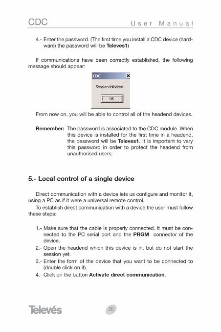
If communications have been correctly established, the followingmessage should appear:
From now on, you will be able to control all of the headend devices.
Remember: The password is associated to the CDC module. Whenthis device is installed for the first time in a headend,the password will be Televes1. It is important to varythis password in order to protect the headend fromunauthorised users.
5.- Local control of a single device
Direct communication with a device lets us configure and monitor it,using a PC as if it were a universal remote control.
To establish direct communication with a device the user must followthese steps:
1.- Make sure that the cable is properly connected. It must be con-nected to the PC serial port and the PRGM connector of thedevice.
2.- Open the headend which this device is in, but do not start thesession yet.
3.- Enter the form of the device that you want to be connected to(double click on it).
4.- Click on the button Activate direct communication.
CDCU s e r M a n u a l
EN
GL
ISH
NOTE: You will only be able to establish direct communications witha device when there is no other ongoing session. Also, thedrawn device must have the same address as the real devi-ce.
5.1.- Identifying a device
This tool lets the user obtain the main data of a device, such as itsaddress, reference and description. It can also automatically draw thedevice on a blank page or add it to a headend that has already beendrawn.
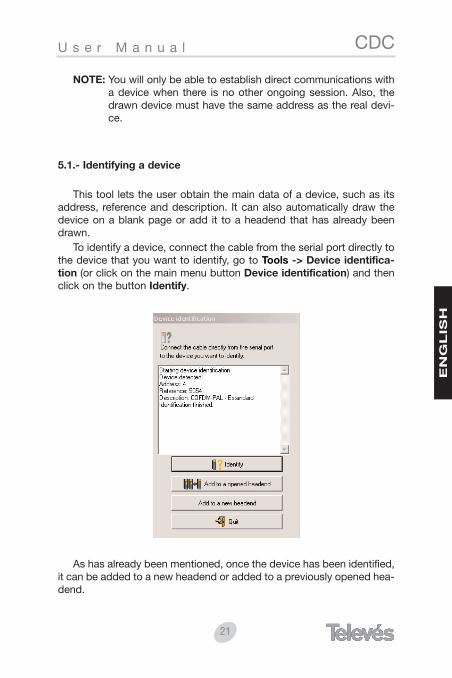
To identify a device, connect the cable from the serial port directly tothe device that you want to identify, go to Tools -> Device identifica-tion (or click on the main menu button Device identification) and thenclick on the button Identify.
As has already been mentioned, once the device has been identified,it can be added to a new headend or added to a previously opened hea-dend.
21
22
CDC U s e r M a n u a l
The menu Tools -> Device identification is only available when nosession is open.
5.2.- Configuration and adjustment of an AVANT 5 using theHeadend Management software.
Next we will show you how to configure and adjust an AVANT 5 usingthe Headend Management software. This software, apart from allowingus to remotely control this type of headend, also simplifies its use andconguration thanks to an intuitive and detailed user interface whichimmediately establishes all the necessary configuration parameters andidentifies the adjustment and operational status of the unit.
Let’s suppose that the PC that is supporting the Headend Controlprogram is directly connected to an Avant 5 ( see section "Local controlof a single device -> Direct communication"). It operates in the sameway as in the case of a remote or local connection via a CDC module; inall cases the PC lets us configure the amplifier as though it were a uni-versal remote control.
Once the PC is connected to the Avant using the communicationscable, the Headend Control program is executed. In the "Direct commu-nications" mode, the tool "Identify device" is a very convenient mode togenerate a quick headend and access the device in question. To do this,press the Tools menu and the "Device identification" option. The follo-wing will appear:

CDCU s e r M a n u a l
EN
GL
ISH
Device identification
Avant 5 added to a new headend
23
24
CDC U s e r M a n u a l
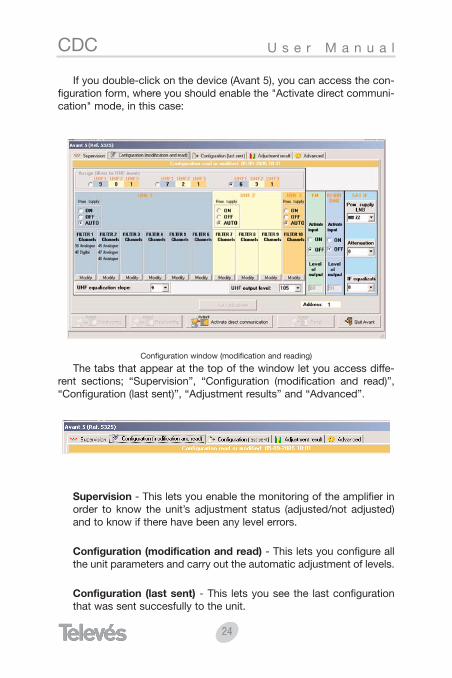
If you double-click on the device (Avant 5), you can access the con-figuration form, where you should enable the "Activate direct communi-cation" mode, in this case:
Configuration window (modification and reading)
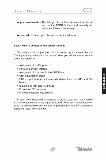
The tabs that appear at the top of the window let you access diffe-rent sections; “Supervision”, “Configuration (modification and read)”,“Configuration (last sent)”, “Adjustment results” and “Advanced”.
Supervision - This lets you enable the monitoring of the amplifier inorder to know the unit’s adjustment status (adjusted/not adjusted)and to know if there have been any level errors.
Configuration (modification and read) - This lets you configure allthe unit parameters and carry out the automatic adjustment of levels.
Configuration (last sent) - This lets you see the last configurationthat was sent succesfully to the unit.
CDCU s e r M a n u a l
EN
GL
ISH
Adjustment results - This lets you know the adjustment results ofeach of the AVANT 5 filters and manually re-adjust each level if necessary.
Advanced - This lets you change the device address.
5.2.1.- How to configure and adjust the unit.
To configure and adjust the unit it is necessary to access the tab“Configuration (modification and read)”. Here you will be able to set theadequate values for:
Assigment of UHF inputsPowering of UHF intputsAssigment of channels to the UHF filtersUHF equalization slopeUHF output level (it automatically determines the VHF and FMlevels)Enabling of VHF and FM inputsPowering LNB convertorIF attenuation and equalization
In each UHF filter, it will be possible to group together a maximum of5 channels (analogue or digital) as indicated. To do so, it is necessary togo to the channel selection window by pressing the “Modify” button thatappears in each UHF channel.
25
26
CDC U s e r M a n u a l
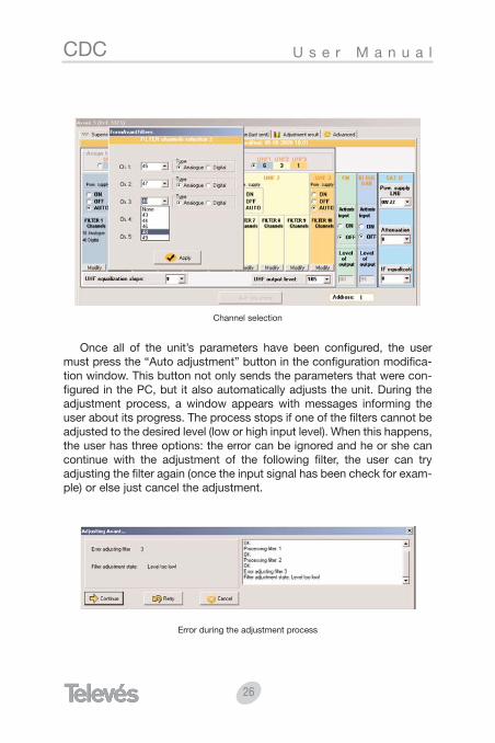
Channel selection
Once all of the unit’s parameters have been configured, the usermust press the “Auto adjustment” button in the configuration modifica-tion window. This button not only sends the parameters that were con-figured in the PC, but it also automatically adjusts the unit. During theadjustment process, a window appears with messages informing theuser about its progress. The process stops if one of the filters cannot beadjusted to the desired level (low or high input level). When this happens,the user has three options: the error can be ignored and he or she cancontinue with the adjustment of the following filter, the user can tryadjusting the filter again (once the input signal has been check for exam-ple) or else just cancel the adjustment.
Error during the adjustment process
CDCU s e r M a n u a l
EN
GL
ISH
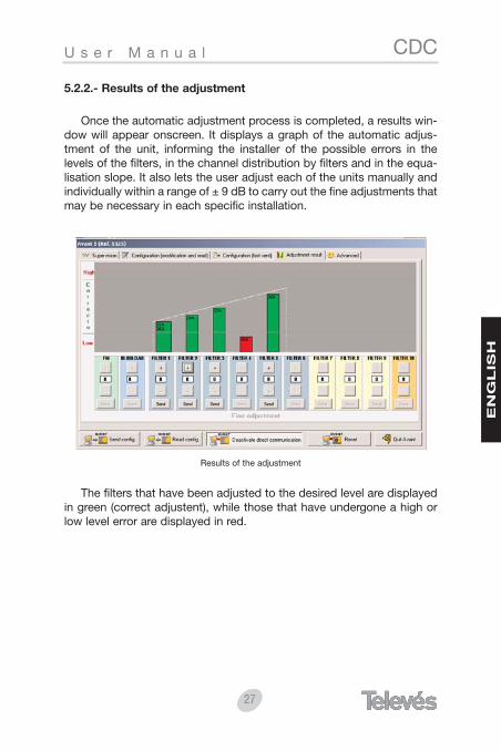
5.2.2.- Results of the adjustment
Once the automatic adjustment process is completed, a results win-dow will appear onscreen. It displays a graph of the automatic adjus-tment of the unit, informing the installer of the possible errors in thelevels of the filters, in the channel distribution by filters and in the equa-lisation slope. It also lets the user adjust each of the units manually andindividually within a range of ± 9 dB to carry out the fine adjustments thatmay be necessary in each specific installation.
Results of the adjustment
The filters that have been adjusted to the desired level are displayedin green (correct adjustent), while those that have undergone a high orlow level error are displayed in red.
27
28
CDC U s e r M a n u a l
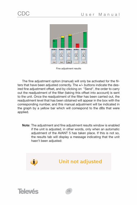
Fine adjustment results
The fine adjustment option (manual) will only be activated for the fil-ters that have been adjusted correctly. The +/- buttons indicate the des-ired fine adjustment offset, and by clicking on "Send", the order to carryout the readjustment of the filter (taking this offset into account) is sentto the unit. Once the readjustment of the filter has been carried out, thereadjustment level that has been obtained will appear in the box with thecorresponding number, and this manual adjustment will be indicated inthe graph by a yellow bar which will correspond to the dBs that wereapplied.
Note: The adjustment and fine adjustment results window is enabledif the unit is adjusted, in other words, only when an automaticadjustment of the AVANT 5 has taken place. If this is not so,the results tab will display a message indicating that the unithasn’t been adjusted:
29
CDCU s e r M a n u a l
EN
GL
ISH
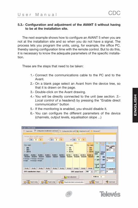
5.3.- Configuration and adjustment of the AVANT 5 without havingto be at the installation site.
The next example shows how to configure an AVANT 5 when you arenot at the installation site and so when you do not have a signal. Theprocess lets you program the units, using, for example, the office PC,thereby saving configuration time with the remote control. But to do this,it is necessary to know the adequate parameters of the specific installa-tion.
These are the steps that need to be taken:
1.- Connect the communications cable to the PC and to theAvant.
2.- On a blank page select an Avant from the device tree, sothat it is drawn on the page.
3.- Double-click on the Avant drawing.4.- You will be directly connected to the unit (see section. 3.-
Local control of a headend) by pressing the "Enable directcommunication" button
5.- If the monitoring is enabled, you should disable it.6.- You can configure the different parameters of the device
(channels, output levels, equalisation slope ...)
30
CDC U s e r M a n u a l
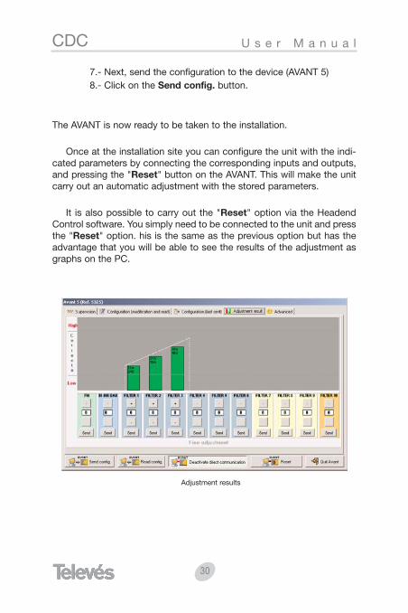
7.- Next, send the configuration to the device (AVANT 5)8.- Click on the Send config. button.
The AVANT is now ready to be taken to the installation.
Once at the installation site you can configure the unit with the indi-cated parameters by connecting the corresponding inputs and outputs,and pressing the "Reset" button on the AVANT. This will make the unitcarry out an automatic adjustment with the stored parameters.
It is also possible to carry out the "Reset" option via the HeadendControl software. You simply need to be connected to the unit and pressthe "Reset" option. his is the same as the previous option but has theadvantage that you will be able to see the results of the adjustment asgraphs on the PC.
Adjustment results
31
CDCB e d i e n u n g s a n l e i t u n g
DE
UT
SC
H
Inhaltsverzeichnis Seite
1.- Anforderungen . . . . . . . . . . . . . . . . . . . . . . . . . . . . . . . . . 32
2.- Installation . . . . . . . . . . . . . . . . . . . . . . . . . . . . . . . . . . . . 33
3.- Fernbedienung der Kopfstelle . . . . . . . . . . . . . . . . . . . . . 33
4.- Direkte Bedienung einer Kopfstelle . . . . . . . . . . . . . . . . 33
5.- Direkte Bedienung eines einzigen Gerätes . . . . . . . . . . 34
5.1.- Gerät identifizieren . . . . . . . . . . . . . . . . . . . . . . . . . . . 35
5.2.- Konfiguration und Einstellung einer AVANT 5 . . . . .mittels Programmiersoftware für Kopfstellen . . . . . . . 36
5.2.1.- Konfiguration und Einstellung der Einheit durchführen . . . . . . . . . . . . . . . . . . . . 39
5.2.2.- Ergebnis der Einstellung . . . . . . . . . . . . . . . . . . . 41
5.3.- Konfiguration und Einstellung einer AVANT 5 . . . .ohne sich in der Installation befinden zu müssen . . . . 43
32
CDC B e d i e n u n g s a n l e i t u n g
1.- Anforderungen
MINDESTANFORDERUNGEN:
PC der Pentium II-Klasse
64 Mb RAM
CD-ROM 2x
20 MB freier Festplattenspeicher
Windows 98/NT/2000/XP
Empfohlen:
PC der Pentium IV-Klasse oder besser
256 Mb RAM
CD-ROM 12x
22 MB freier Festplattenspeicher
Windows 2000/XP

33
CDCB e d i e n u n g s a n l e i t u n g
DE
UT
SC
H
2.- Installation
Das Programm für Betreibung der Kopfstellen wird in einem CD-ROM für Windows angeboten. Um das Programm zu installieren legenSie die CD-ROM in das Laufwerk ein. Folgen Sie dann den Anweisungenauf dem Bildschirm. Wenn das Programm nicht automatisch startensollte weil diese Option ausgeschaltet ist, müssen Folgende Schrittedurchgeführt werden:
Klicken Sie doppelt auf das Ikon "Mein PC" des WindowsDesktops.Im Dialogfenster "Mein PC", klicken Sie doppelt auf das Ikon desCD-ROM- Laufwerkes (normalerweise D:\)Im Dialogfenster der CD-ROM-Einheit klicken Sie doppelt auf"setup.exe".Folgen Sie den Anweisungen auf dem Bildschirm.
Wenn die Installierung beendet ist wird die Programmiersoftware fürKopfstellen bei einem Doppeltklick auf das entsprechende Ikon starten
.
3.- Fernbedienung der Kopfstelle
Sie werden die ausführliche Information über dieses Thema sowohlin den Gebrauchsanweisungen als auch in der Hilfe derProgrammiersoftware für Kopfstellen finden.
4.- Direkte Bedienung einer Kopfstelle
Bevor Sie eine Session im Direktmodus starten Vergewissern Sie sichdass das gewählte Laufwerk für die Verbindung korrekt ist mit Hilfe desMenü "Konfiguration \Verbindung". Das Verbindungskabel muss einer-seits an den seriellen Port des PCs und anderseits an den mit PRGMgekennzeichneten Konnektor des CDC Gerätes angeschlossen werden.
34
CDC B e d i e n u n g s a n l e i t u n g
1.- Lassen Sie das Feld Modem anwenden im Menü "SessionKontrolle" unselektiert.
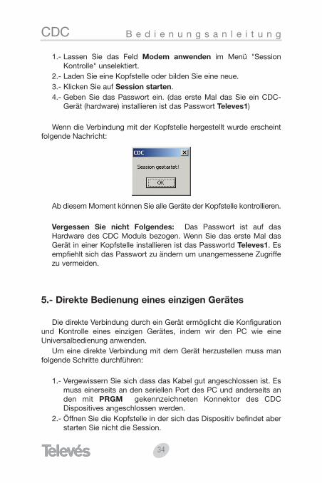
2.- Laden Sie eine Kopfstelle oder bilden Sie eine neue.3.- Klicken Sie auf Session starten.4.- Geben Sie das Passwort ein. (das erste Mal das Sie ein CDC-
Gerät (hardware) installieren ist das Passwort Televes1)
Wenn die Verbindung mit der Kopfstelle hergestellt wurde erscheintfolgende Nachricht:
Ab diesem Moment können Sie alle Geräte der Kopfstelle kontrollieren.
Vergessen Sie nicht Folgendes: Das Passwort ist auf dasHardware des CDC Moduls bezogen. Wenn Sie das erste Mal dasGerät in einer Kopfstelle installieren ist das Passwortd Televes1. Esempfiehlt sich das Passwort zu ändern um unangemessene Zugriffezu vermeiden.
5.- Direkte Bedienung eines einzigen Gerätes
Die direkte Verbindung durch ein Gerät ermöglicht die Konfigurationund Kontrolle eines einzigen Gerätes, indem wir den PC wie eineUniversalbedienung anwenden.
Um eine direkte Verbindung mit dem Gerät herzustellen muss manfolgende Schritte durchführen:
1.- Vergewissern Sie sich dass das Kabel gut angeschlossen ist. Esmuss einerseits an den seriellen Port des PC und anderseits anden mit PRGM gekennzeichneten Konnektor des CDCDispositives angeschlossen werden.
2.- Öffnen Sie die Kopfstelle in der sich das Dispositiv befindet aberstarten Sie nicht die Session.
35
CDCB e d i e n u n g s a n l e i t u n g
DE
UT
SC
H
3.- Greifen Sie zu auf das Formular des Dispositives (Doppeltklick).4.- Klicken Sie auf Direkte Verbindung aktivieren.
VERMERK: Die direkte Verbindung zu einem Dispositiv kann nur her-gestellt werden wenn keine Session geöffnet ist.Außerdem muss das abgebildete Gerät die gleicheAdresse haben wie das materielle.
5.1.- Gerät identifizieren
Dieses Werkzeug ermöglicht es die wichtigsten Daten des Gerätes zubekommen, wie z.B. Adresse, Referenz und Beschreibung. Außerdemkann das Gerät sofort neu abgebildet werden oder zu einem abgebilde-ten Kopfstelle hinzugefügt werden.
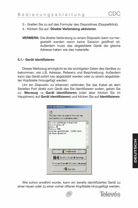
Um ein Dispositiv zu erkennen verbinden Sie das Kabel ab demSeriellen Port direkt zum Gerät das Sie identifizieren wollen, gehen Siezu: Werzeug -> Gerät identifizieren (oder aber klicken Sie imHauptmenü auf Gerät identifizieren) und klicken Sie auf Identifizieren.
Wie schon erwähnt wurde, kann ein bereits identifiziertes Gerät zueiner neuen oder zu einer vorher offenen Kopfstelle hinzugefügt werden.
36
CDC B e d i e n u n g s a n l e i t u n g
Das Menü Werkzeug -> Gerät identifizieren ist nur verfügbar wennkeine Session geöffnet ist.
5.2.- Konfiguration und Einstellung einer AVANT 5 mittelsProgrammiersoftware für Kopfstellen.
Anschließend wird gezeigt wie eine AVANT 5- Zentrale konfiguriertund eingestellt wird mit dem Programmiersoftware für Kopfstellen. DieseKontrollesoftware bietet nicht nur die Möglichkeit diese Art vonZentralen fernzubedienen sondern vereinfacht auch ihre Bedienung undKonfiguration aufgrund ihres intuitiven und detailliertenBenutzerinterface am PC das eine sofortige Errichtung der nötigenKonfigurationsparametern und Identifizierung der Einstellung undArbeitsweise der Einheit ermöglicht.
Wir nehmen an dass der PC, auf dem das Programmiersoftware fürKopfstellen Abläuft, direkt mit einer Avant 5 verbunden ist (siehe Absatz"Direkte Bedienung eines einzigen Gerätes -> Direkte Verbindung"). DieBedienung ist identisch wie im Fall einer Fern- oder einer direktenBedienung durch ein CDC Modul, in allen Fällen ist es möglich dieZentrale zu konfigurieren indem man den PC wie eineUniversalbedienung anwendet.
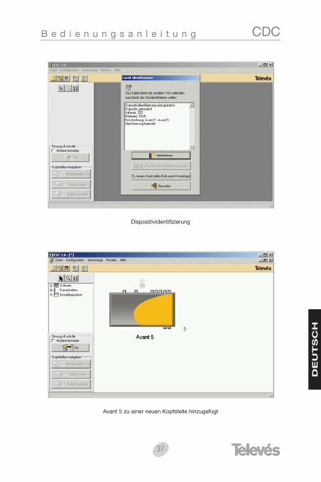
Wenn der PC mit dem Verbindungskabel richtig an der Avant anges-chlossen wurde, startet man das Programmiersoftware für Kopfstellen.Im Modus "Direkte Verbindung" kann mit dem Werkzeug "Gerät identifi-zieren" sehr gut sofort eine Kopfstelle erzeugt werden um auf das inFrage kommende Gerät zuzugreifen, dazu muss man das MenüWerkzeug drücken und auf die Option "Gerät identifizieren" klicken, wasdann das folgende Bildschirm zeigt:
37
CDCB e d i e n u n g s a n l e i t u n g
DE
UT
SC
H
Dispositividentifizierung
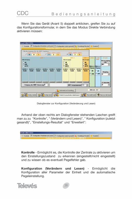
Avant 5 zu einer neuen Kopfstelle hinzugefügt
38
CDC B e d i e n u n g s a n l e i t u n g
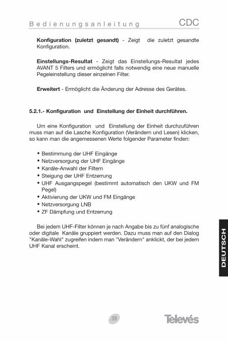
Wenn Sie das Gerät (Avant 5) doppelt anklicken, greifen Sie zu aufdas Konfigurationsformular, in dem Sie das Modus Direkte Verbindungaktivieren müssen:
Dialogfenster zur Konfiguration (Veränderung und Lesen)
Anhand der oben rechts am Dialogfenster stehenden Laschen greiftman zu zu "Kontrolle", " (Verändern und Lesen)", " Konfiguration (zuletztgesandt)", "Einstellungs-Resultat" und "Erweitert":
Kontrolle - Ermöglicht es, die Kontrolle der Zentrale zu aktivieren umden Einstellungszustand zu erkennen (eingestellt/nicht eingestellt)und zu wissen ob es eventuell Pegelfehler gab.
Konfiguration (Verändern und Lesen) - Ermöglicht dieKonfiguration aller Parameter der Einheit und die automatischePegeleinstellung.
39
CDCB e d i e n u n g s a n l e i t u n g
DE
UT
SC
H
Konfiguration (zuletzt gesandt) - Zeigt die zuletzt gesandteKonfiguration.
Einstellungs-Resultat - Zeigt das Einstellungs-Resultat jedesAVANT 5 Filters und ermöglicht falls notwendig eine neue manuellePegeleinstellung dieser einzelnen Filter.
Erweitert - Ermöglicht die Änderung der Adresse des Gerätes.
5.2.1.- Konfiguration und Einstellung der Einheit durchführen.
Um eine Konfiguration und Einstellung der Einheit durchzuführenmuss man auf die Lasche Konfiguration (Verändern und Lesen) klicken,so kann man die angemessenen Werte folgender Parameter finden:
Bestimmung der UHF EingängeNetzversorgung der UHF EingängeKanäle-Anwahl der FilternSteigung der UHF EntzerrungUHF Ausgangspegel (bestimmt automatisch den UKW und FMPegel)Aktivierung der UKW und FM EingängeNetzversorgung LNBZF Dämpfung und Entzerrung
Bei jedem UHF-Filter können je nach Angabe bis zu fünf analogischeoder digitale Kanäle gruppiert werden. Dazu muss man auf den Dialog"Kanäle-Wahl" zugreifen indem man "Verändern" anklickt, der bei jedemUHF Kanal erscheint.

40
CDC B e d i e n u n g s a n l e i t u n g
Kanäle- Anwahl
Wenn alle Einheitsparameter konfiguriert wurden muss man auf"automatische Einstellung" im Dialogfenster "Konfiguration ändern" klic-ken. Dieser Knopf sendet nicht nur die konfigurierten Parameter desPCs, er stellt auch automatisch die Einheit ein. Währen desEinstellungsprozesses öffnet sich ein Dialogfenster das dem Benutzerdie Nachrichten dieses Verlaufes zeigt. Der Prozess hält an wenn einbestimmter Filter nicht auf den gewünschten Pegel eingestellt werdenkann (Eingangspegel zu tief oder zu hoch). Wenn das passiert, kann derBenutzer zwischen drei Optionen wählen: er kann den Fehler ignorierenund mit dem nächsten Filter weitermachen, den Einstellungsprozesswiederholen (nachdem er z.B. das Eingangssignal kontrolliert hat) oderaber die Einstellung abbrechen.
Fehler der Einstellung
41
CDCB e d i e n u n g s a n l e i t u n g
DE
UT
SC
H
5.2.2.- Einstellungs-Resultat.
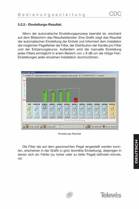
Wenn der automatische Einstellungsprozess beendet ist, erscheintauf dem Bildschirm das Resultatsfenster. Eine Grafik zeigt das Resultatder automatischen Einstellung der Einheit und informiert dem Installatordie möglichen Pegelfehler der Filter, der Distribution der Kanäle pro Filterund der Entzerrungskurve. Außerdem wird die manuelle Einstellungjedes Filters ermöglicht in enem Bereich von ± 9 dB um die nötige Fein-Einstellungen jeder einzelnen Installation durchzuführen.
Einstellungs-Resultat
Die Filter die auf dem gewünschten Pegel eingestellt werden konn-ten, erscheinen in der Grafik in grün (korrekte Einstellung), diejenigen indenen sich ein Fehler (zu hoher oder zu tiefer Pegel) befinden könnte,rot.
42
CDC B e d i e n u n g s a n l e i t u n g
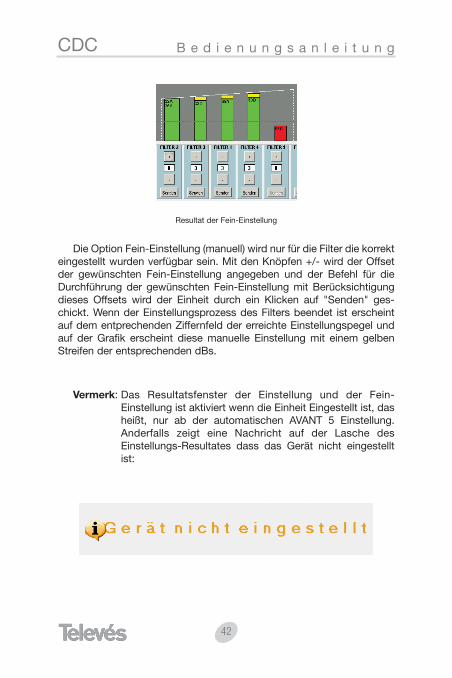
Resultat der Fein-Einstellung
Die Option Fein-Einstellung (manuell) wird nur für die Filter die korrekteingestellt wurden verfügbar sein. Mit den Knöpfen +/- wird der Offsetder gewünschten Fein-Einstellung angegeben und der Befehl für dieDurchführung der gewünschten Fein-Einstellung mit Berücksichtigungdieses Offsets wird der Einheit durch ein Klicken auf "Senden" ges-chickt. Wenn der Einstellungsprozess des Filters beendet ist erscheintauf dem entprechenden Ziffernfeld der erreichte Einstellungspegel undauf der Grafik erscheint diese manuelle Einstellung mit einem gelbenStreifen der entsprechenden dBs.
Vermerk: Das Resultatsfenster der Einstellung und der Fein-Einstellung ist aktiviert wenn die Einheit Eingestellt ist, dasheißt, nur ab der automatischen AVANT 5 Einstellung.Anderfalls zeigt eine Nachricht auf der Lasche desEinstellungs-Resultates dass das Gerät nicht eingestelltist:

43
CDCB e d i e n u n g s a n l e i t u n g
DE
UT
SC
H
5.3.- Konfiguration und Einstellung einer AVANT 5 ohne sich in derInstallation befinden zu müssen.
Das folgende Beispiel zeigt uns wie AVANT 5 konfiguriert werdenkann wenn man sich nicht in der Installation befindet und daher keinSignal hat. Dieser Prozess ermöglicht die Programmierung der Einheitenmit dem PC im Büro z.B., und man spart so Konfigurationszeit mit derSteuerung auf der Kopfstelle. Aber dazu muss man die passendenParameter der Installation kennen.
Folgende Schritte müssen durchgeführt werden:
1.- Verbindungskabel ab dem PC zu Avant anschließen.2.- Auf einem unbeschriebenen Schema eine Avant aus der
Baumdarstellung der Geräte wählen damit diese imSchema abgebildet wird.
3.- Doppelt Klicken wird auf der Zeichnung des Avant betätigt4.- Durch die Direkte Verbindung (siehe Absatz 3: Direkte
Bedienung einer Kopfstelle) mit der Einheit verbinden, durchdoppelt "Direkte Verbindung aktivieren" anzuklicken.
5.- Kontrolle unaktivieren wenn sie aktiviert sein sollte.6.- die verscheidenen Parameter des Gerätes konfigurieren
(Kanäle, Ausgangspegel, Steigung der Entzerrung...)

44
CDC B e d i e n u n g s a n l e i t u n g
7.- Konfiguration dem Gerät (AVANT 5) senden8.- Auf Konfiguration senden klicken.
In diesem Moment ist die AVANT bereit zur Durchführung derInstallation.
Wenn man sich in der Installation befindet werden die entsprechen-den Ein- und Ausgänge verbunden um die Einheit mit den angegebenParametern zu starten, und der Knopf "Reset" der AVANT gedrückt,dadurch durchführt die Einheit eine automatische Einstellung mit dengespeicherten Parametern.
Der "Reset" kann auch mit dem Programmiersoftware fürKopfstellen durchführt werden. Man muss dazu nur die Einheit ans-chließen und auf "Neustart (Reset)" klicken, was dem vorigen Vorgangentspricht und den Vorteil hat, dass das Einstellungs-Resultat auf demPC grafisch beobachtet werden kann.
Einstellungs-Resultat


����
�������
�����
�� ���
������
��������
�����
������
������
���������
����� �
�������� �������
���� �����
������������
��������
��� �
���������
������
����������������
����������
����������
������
� ������
�������
������
������
����
����
�������
�������
�������
�������
�������
������
������
����������
������
��������������
��������
�������
��������
�� �����
��� ���
����������
������
����
����
��������
����
�������
�������������
�������
��������
� �����
Rúa B. de Conxo, 17
C.P. 15706 SANTIAGO DE COMPOSTELA
Tel.: 981 52 22 00 Fax: 981 52 22 62
[email protected] www.televes.com
RReedd CCoommeerrcciiaall NNaacciioonnaall
���� !"�#��$%��!"�#�&
���''()*)+(
���������������
A CORUÑAGregorio Hernández 8. - C.P. 15011 Tfnos: 981 27 47 31 /981 27 22 10Fax: 981 27 16 [email protected]
ALMERÍACampogrís 9. - C.P. 04008Tfno.: 950 23 14 43Fax: 950 23 14 [email protected]
BADAJOZC/ Jacobo Rodríguez Pereira,nº11-Oficina. - C.P. 06010Tfno.: 924 20 74 83 Móvil: 670 70 21 93Fax: 924 20 01 [email protected]
BARCELONAC/ Sant Ferrán, 27.Cornellá. - C.P. 08940 Tfnos.:93 377 08 62 /93 474 29 50Fax: 93 474 50 [email protected]
BILBAOIberre Kalea, módulo 16,pabellón 15-BSangroniz-Sondika - C.P. 48150Tfnos.:94 471 12 02 /94 471 24 78Fax: 94 471 14 [email protected]
BURGOSC/ Real, s/n, San Adrián de JuarrosC.P. 09188Tfno.: 947 56 04 58Móvil: 670 73 75 [email protected]
GIJÓNC/ Japón, 14. - C.P. 33210Tfnos.:985 15 25 50 /985 15 29 67Fax: 985 14 63 [email protected]
JAÉNHermanos Pinzón, 8-bajo.C.P. 23007Tfnos.:953 29 50 40 /953 29 52 11Móvil: 636 984489 Fax: 953 29 52 [email protected]
LAS PALMASGral. Mas de Gaminde 26.C.P. 35006Tfnos.:928 23 11 22 /928 23 12 42Fax: 928 23 13 [email protected]
LOGROÑOSan Prudencio 19. bajo. - C.P. 26004 Tfno.: 941 23 35 24Fax: 941 25 50 [email protected]
MADRIDPaseo de los Pontones 11.C.P. 28005Tfnos.:91 474 52 21 /91 474 52 22Fax: 91 474 54 [email protected]
MÁLAGAPol. Ind. Alameda 2.C/ La Boheme, 55. - C.P. 29006Tfno.: 952 03 82 26Fax: 952 03 82 22 [email protected]
MURCIAPolígono ConverC/ Rio Pliego 22. - C.P. 30010Tfnos.:968 26 31 44 /968 26 31 77Fax: 968 25 25 [email protected]
PAMPLONAAvd. Sancho el Fuerte 5. - C.P. 31007Tfno.: 948 27 35 10Fax: 948 17 41 [email protected]
SEVILLAPol. Ind. Store - C/ A-6. Nave 5.C.P. 41008Tfnos.:95 443 64 50 /95 443 58 00 Fax: 95 443 96 [email protected]
PALMA DE MALLORCAFerrer de Pallares 45. bajo D.C.P. 07007Tfno.: 971 24 70 02Fax: 971 24 53 [email protected]
TENERIFEAvd. El Paso, 25. - C.P. 38108Los Majuelos- La LagunaTfnos.:922 31 13 14 /922 31 13 16Fax: 922 31 13 [email protected]
VALENCIAPlaza Jordi San Jordi s/n.C.P. 46022 Tfnos.:96 337 12 01 /96 337 12 72 Fax: 96 337 06 [email protected]
VIGOEscultor Gregorio Fernández, 5.C.P. 36204Tfnos.:986 42 33 87 /986 42 40 44Fax: 986 42 37 [email protected]
VALLADOLIDC/ Arrecife 12. - C.P. 47008Tfno.: 983 22 36 66Fax: 983 22 36 [email protected]
ZARAGOZAC/ Monasterio de Alahón 1-3.C.P. 50002Tfno.: 976 41 12 73Fax: 976 59 86 [email protected]
MANUAL DE INSTRUCCIONESMANUAL OF INSTRUCTIONS
BEDIENUNGSANLE ITUNG
MANUEL D ’ INSTRUCTIONMANUALE D I ISTRUZ IONIMANUAL DE INSTRUÇÕES
TELEVES ITALIA S.r.l.S.op.Viale Liguria 24 20068 Peschiera Borromeo (MI)ItaliaTel.: (+39)-0251650604 (RA)Fax: (+39)[email protected]
TELEVES MIDDLE EAST FZEP.O. Box 17199JEBEL ALI FREE ZONE DUBAI, UNITED ARAB EMIRATESTel.: 9714 88 343 44Fax: 9714 88 346 44 [email protected]
TELEVES UNITED KINGDOM LTDUnit 11 Hill Street, Industrial StateCWMBRAN, GWENT NP44 7PG. (United Kingdom)Tel.: 44 01 633 87 58 21Fax: 44 01 633 86 63 [email protected]
TELEVES FRANCE S.A.R.L.1 Rue Louis de BroglieParc d'Activités de l'Esplanade77400 St Thibault des VignesFRANCETél.:+33 (0)1 60 35 92 10 Fax: +33 (0)1 60 35 90 [email protected]
TELEVES ELECTRONICA PORTUGUESA
RReedd CCoommeerrcciiaall IInntteerrnnaacciioonnaall
MAIA - OPORTOVia . Dr Francisco Sa Carneiro. Lote 17. ZONA Ind. MAIA 1.Sector-X MAIA. C.P. 4470 BARCATel.: 351 22 9418313Fax: 351 22 9488719/[email protected]. 1000 Rua Augusto Gil 21-A.Tel.: 351 21 7932537Fax: 351 21 [email protected]