rectification - Carleton...
13
Rectification Dr. Gerhard Roth
Transcript of rectification - Carleton...
Rectification
Dr. Gerhard Roth
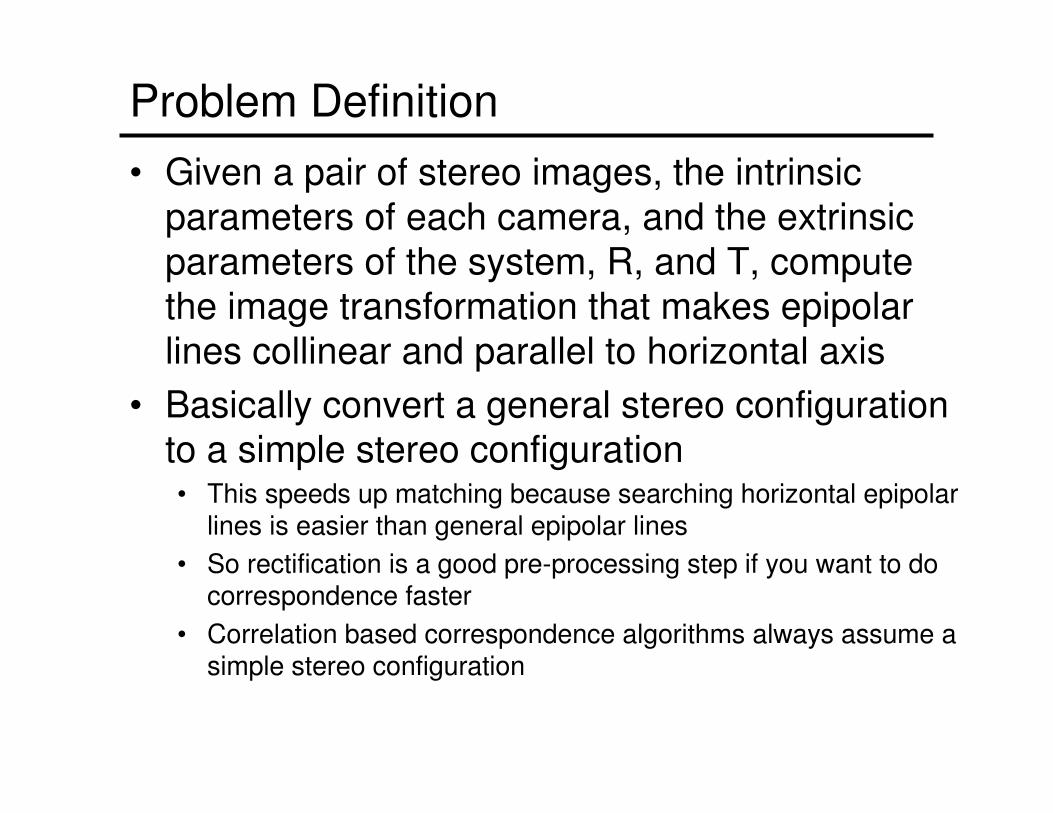
Problem Definition
• Given a pair of stereo images, the intrinsic
parameters of each camera, and the extrinsic
parameters of the system, R, and T, compute
the image transformation that makes epipolar
lines collinear and parallel to horizontal axis
• Basically convert a general stereo configuration
to a simple stereo configuration• This speeds up matching because searching horizontal epipolar
lines is easier than general epipolar lines
• So rectification is a good pre-processing step if you want to do correspondence faster
• Correlation based correspondence algorithms always assume a simple stereo configuration
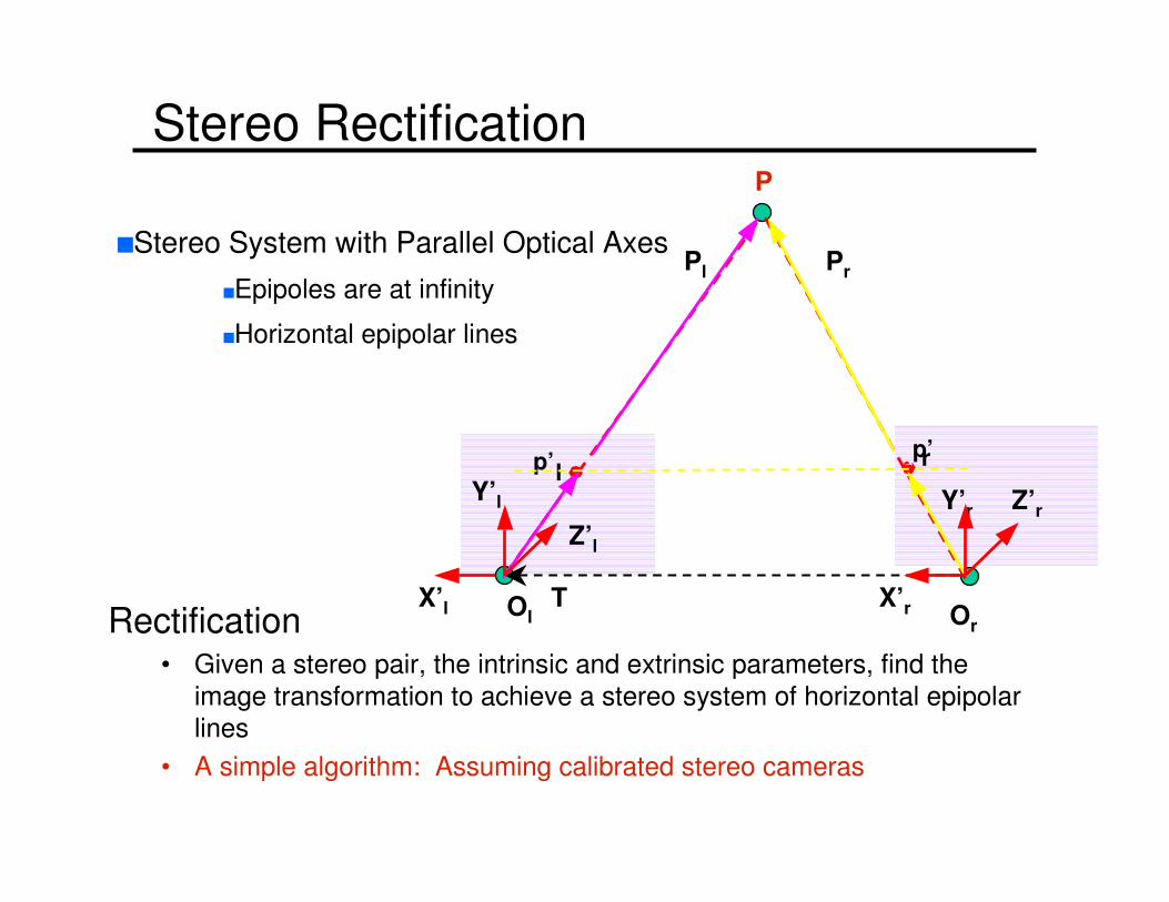
Stereo Rectification
Rectification • Given a stereo pair, the intrinsic and extrinsic parameters, find the
image transformation to achieve a stereo system of horizontal epipolar
lines
• A simple algorithm: Assuming calibrated stereo cameras
p’lp’r
P
Ol Or
X’r
Pl Pr
Z’l
Y’l Y’r
TX’l
Z’r
nStereo System with Parallel Optical Axes
nEpipoles are at infinity
nHorizontal epipolar lines
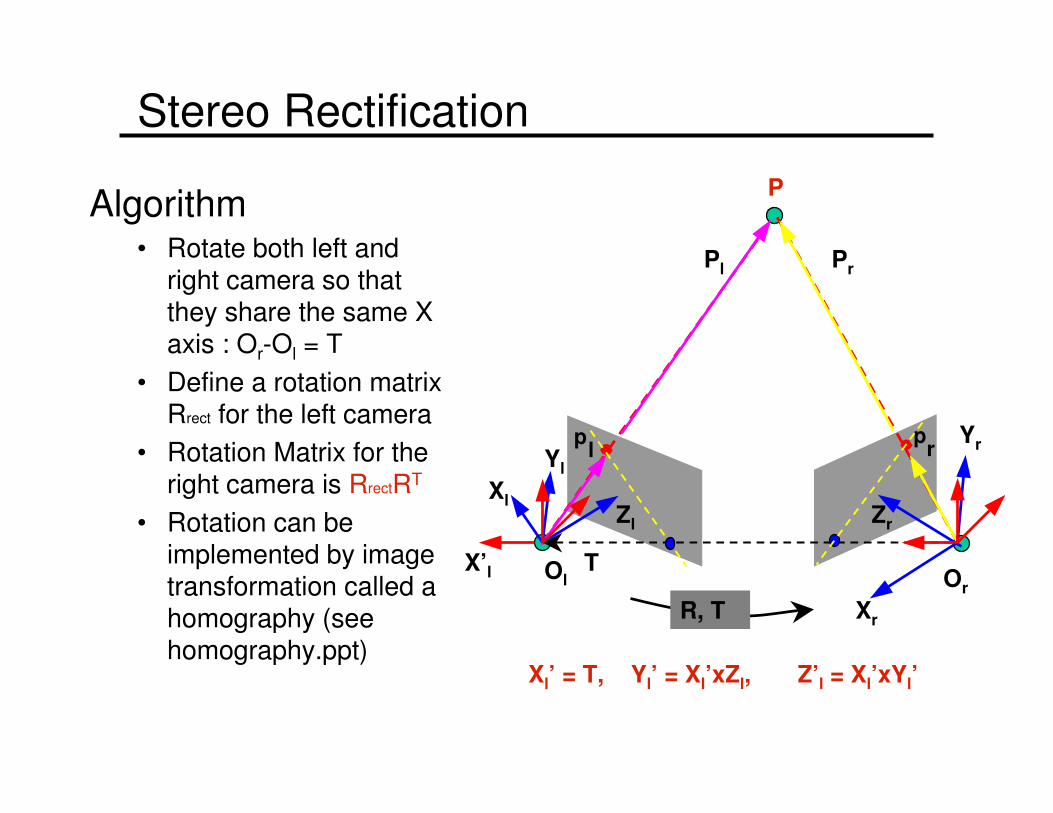
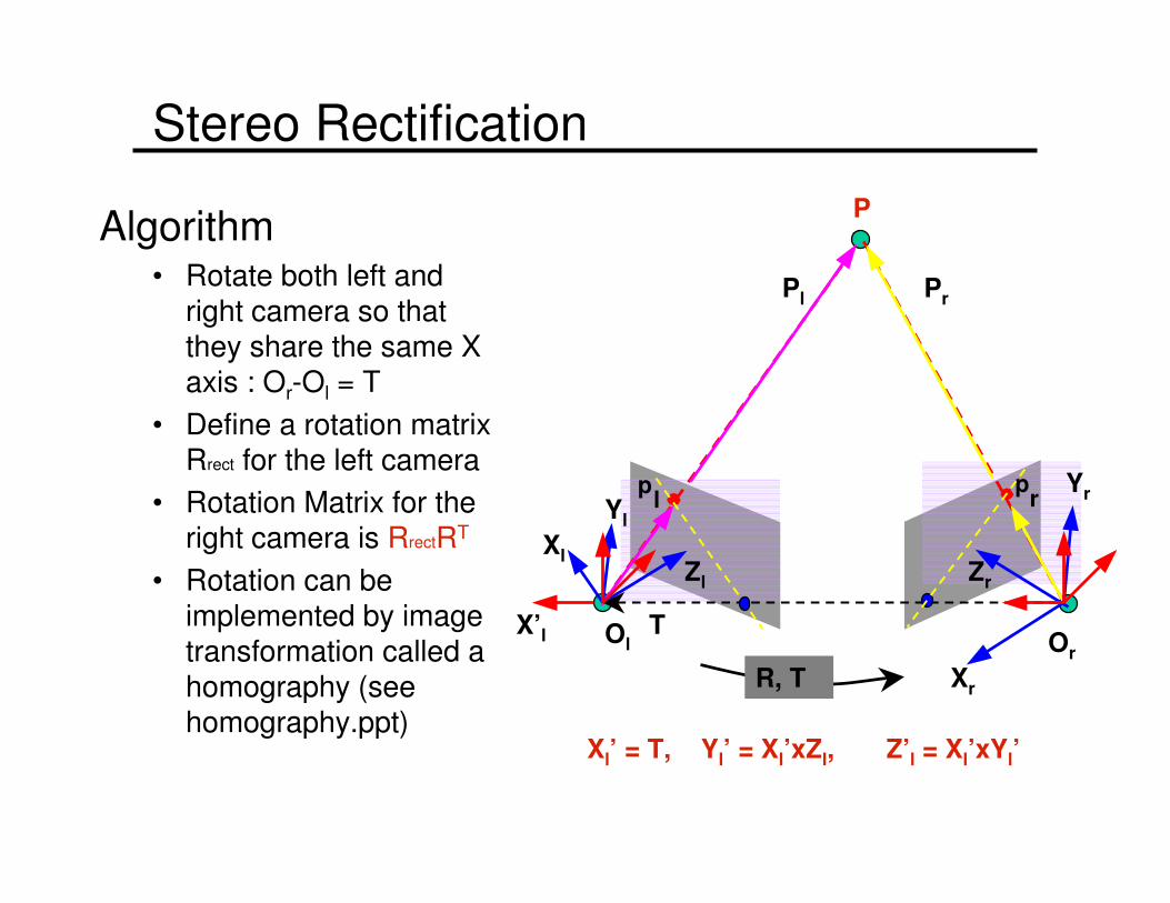
Stereo Rectification
Algorithm• Rotate both left and
right camera so that they share the same X axis : Or-Ol = T
• Define a rotation matrix Rrect for the left camera
• Rotation Matrix for the right camera is RrectRT
• Rotation can be implemented by image transformation called a homography (see homography.ppt)
pl
pr
P
Ol Or
Xl
Xr
Pl Pr
Zl
Yl
Zr
Yr
R, T
TX’l
Xl’ = T, Yl’ = Xl’xZl, Z’l = Xl’xYl’
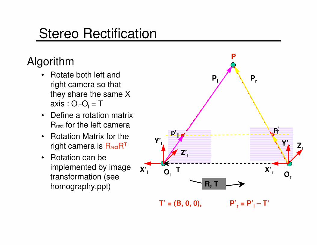
Stereo Rectification
Algorithm• Rotate both left and
right camera so that they share the same X axis : Or-Ol = T
• Define a rotation matrix Rrect for the left camera
• Rotation Matrix for the right camera is RrectRT
• Rotation can be implemented by image transformation (see homography.ppt)
Zr
p’lp’r
P
Ol Or
X’r
Pl Pr
Z’l
Y’l Y’r
R, T
TX’l
T’ = (B, 0, 0), P’r = P’l – T’
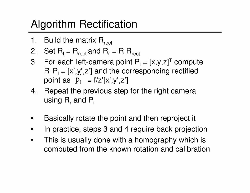
Algorithm Rectification
1. Build the matrix Rrect
2. Set Rl = Rrect and Rr = R Rrect
3. For each left-camera point Pl = [x,y,z]T compute Rl Pl = [x’,y’,z’] and the corresponding rectified
point as = f/z’[x’,y’,z’]
4. Repeat the previous step for the right camera
using Rr and Pr
• Basically rotate the point and then reproject it
• In practice, steps 3 and 4 require back projection
• This is usually done with a homography which is
computed from the known rotation and calibration
'
lp
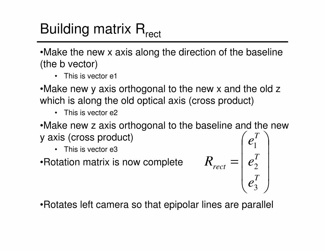
Building matrix Rrect
•Make the new x axis along the direction of the baseline (the b vector)
• This is vector e1
•Make new y axis orthogonal to the new x and the old z which is along the old optical axis (cross product)
• This is vector e2
•Make new z axis orthogonal to the baseline and the new
y axis (cross product)• This is vector e3
•Rotation matrix is now complete
•Rotates left camera so that epipolar lines are parallel
=
T
T
T
rect
e
e
e
R
3
2
1
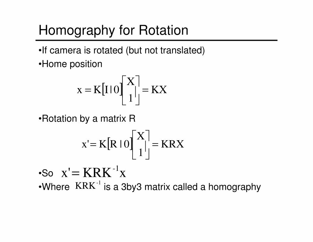
Homography for Rotation
•If camera is rotated (but not translated)
•Home position
•Rotation by a matrix R
•So
•Where is a 3by3 matrix called a homography
[ ] KX1
X0 | IK x =
=
[ ] KRX1
X0|RKx' =
=
xKRKx' -1=
-1KRK
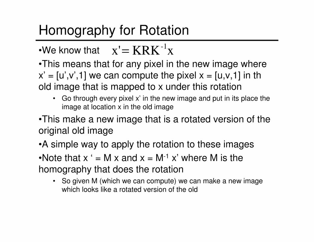
Homography for Rotation
•We know that
•This means that for any pixel in the new image where
x’ = [u’,v’,1] we can compute the pixel x = [u,v,1] in thold image that is mapped to x under this rotation
• Go through every pixel x’ in the new image and put in its place the
image at location x in the old image
•This make a new image that is a rotated version of the original old image
•A simple way to apply the rotation to these images
•Note that x ‘ = M x and x = M-1 x’ where M is the
homography that does the rotation• So given M (which we can compute) we can make a new image
which looks like a rotated version of the old
xKRKx' -1=
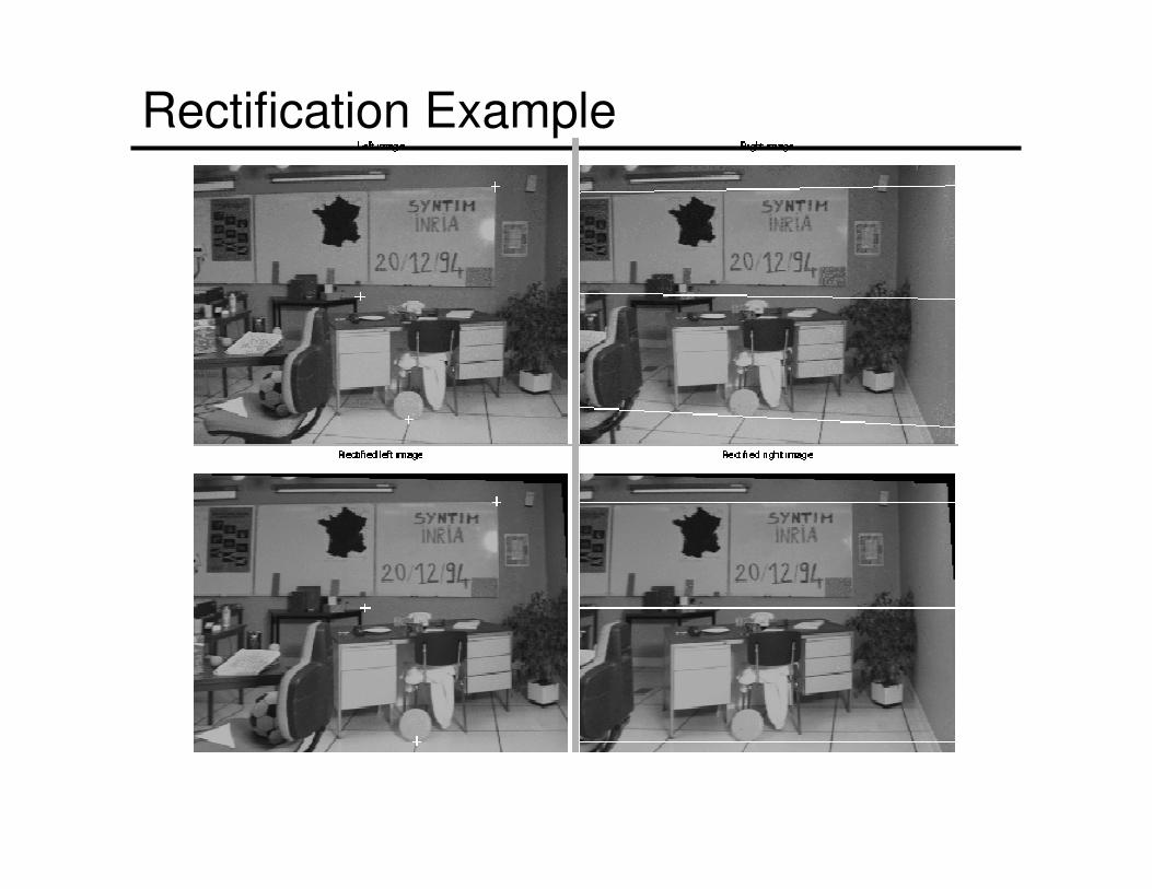
Rectification Example
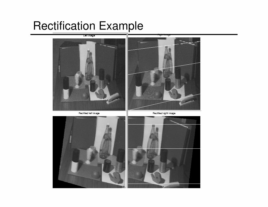
Rectification Example
Rectification
• Used to transform a general stereo system into a simple stereo system
1. Do the rectification to get two new images
2. Do correspondence in the new simple stereo images
3. Take the 3D points that are found and convert them back into the old image frames (invert rotations)
The result is a set of 3D points, but they are computed
more quickly because we do correspondence in
simple stereo.