Rectification and Disparity - Technische Universität...
31
Rectification and Disparity Nassir Navab Slides prepared by Christian Unger
Transcript of Rectification and Disparity - Technische Universität...
Rectification and Disparity
Nassir Navab
Slides prepared by Christian Unger
Rectification and Disparity - Christian Unger 2
What is Stereo Vision?
Introduction
• A technique aimed at inferring dense depth measurements efficiently using
two cameras.
• Wide and old research area in computer vision.
• Contents of the talks:
– Radial Undistortion: Compensate effects of radial lens distortion.
– Rectification: Transforming the epipolar geometry into a canonical form.
– Disparity: Definition and relation to depth.
– Binocular Stereo Matching: The process of establishing dense correspondences
between two images.
– Triangulation: Computing a 3D reconstruction.
Rectification and Disparity - Christian Unger 3
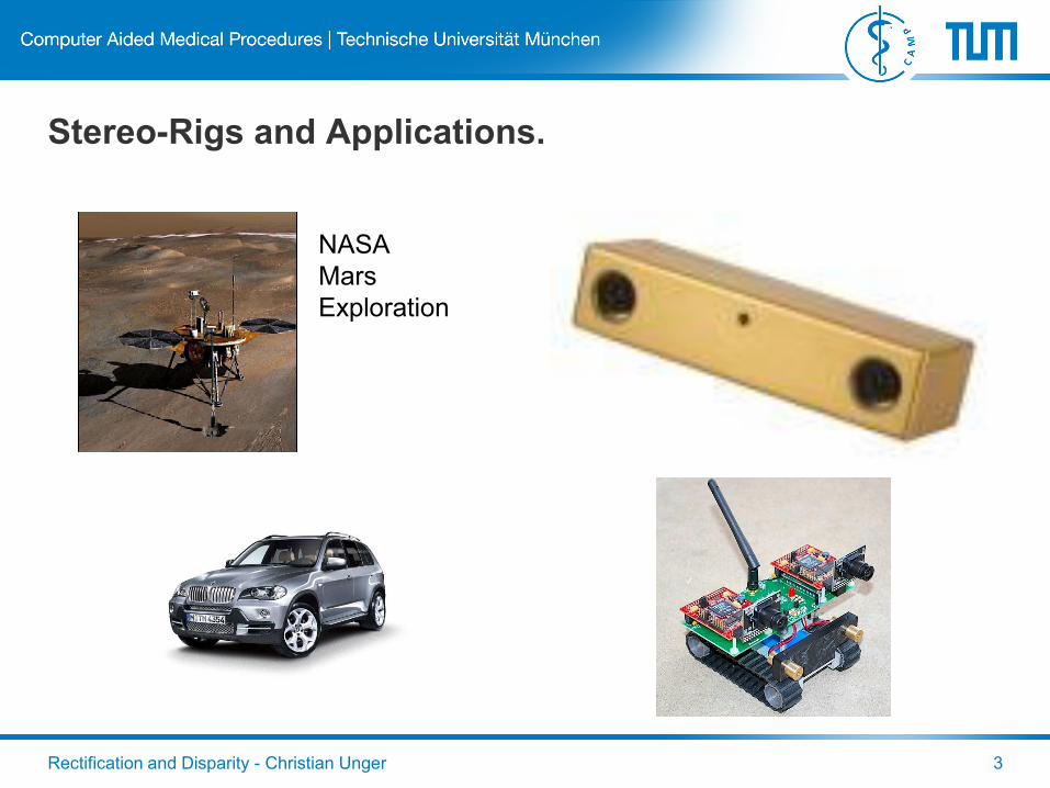
Stereo-Rigs and Applications.
NASA
Mars
Exploration
Rectification and Disparity - Christian Unger 4
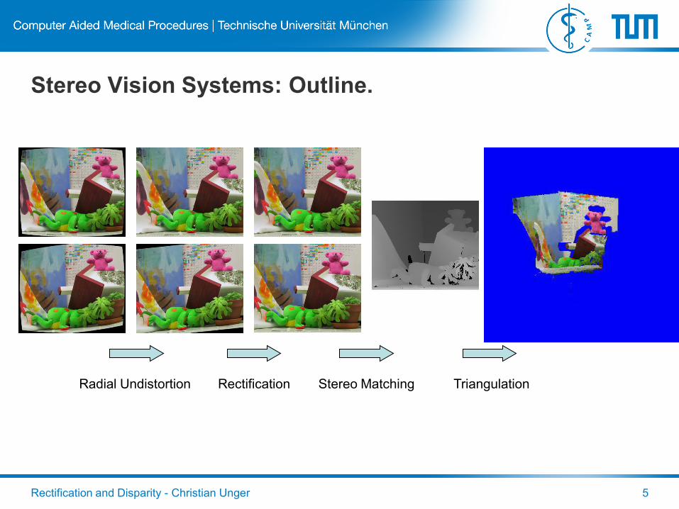
Stereo Vision Systems: Outline.
A Stereo Vision System is usually composed of these processing steps:
1. Radial Undistortion
2. Rectification
3. Stereo Matching
4. Triangulation
Rectification and Disparity - Christian Unger 5
Stereo Vision Systems: Outline.
Radial Undistortion Rectification Stereo Matching Triangulation
Rectification and Disparity - Christian Unger 6
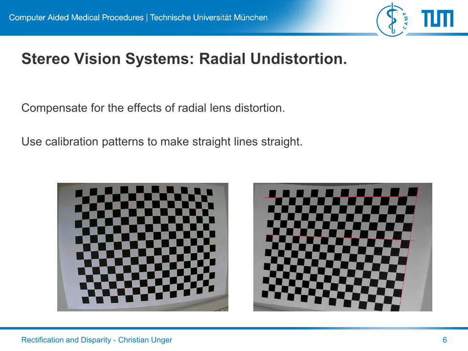
Stereo Vision Systems: Radial Undistortion.
Compensate for the effects of radial lens distortion.
Use calibration patterns to make straight lines straight.
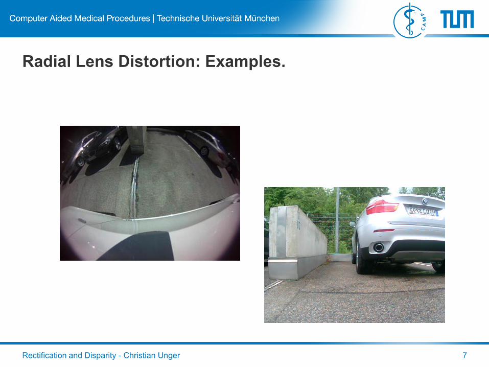
Radial Lens Distortion: Examples.
Rectification and Disparity - Christian Unger 7
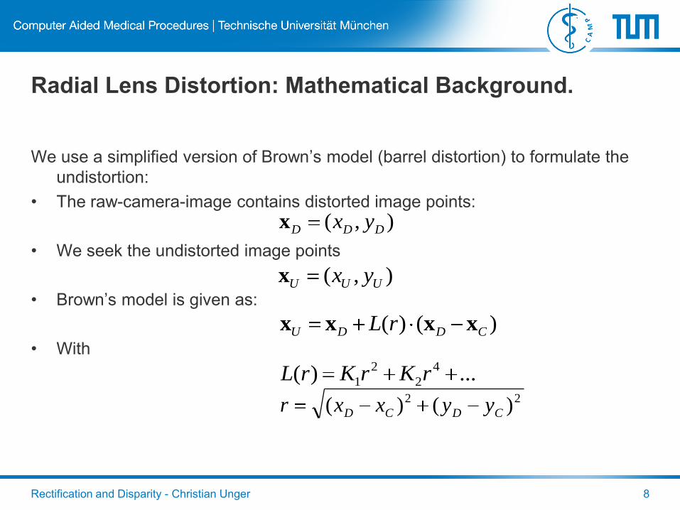
Radial Lens Distortion: Mathematical Background.
We use a simplified version of Brown’s model (barrel distortion) to formulate the
undistortion:
• The raw-camera-image contains distorted image points:
• We seek the undistorted image points
• Brown’s model is given as:
• With
Rectification and Disparity - Christian Unger 8
),( UUU yxx
),( DDD yxx
)()( CDDU rL xxxx
...)( 4
2
2
1 rKrKrL22 )()( CDCD yyxxr

Radial Lens Undistortion: Approach.
Offline phase:
• Estimate the distortion parameters using 2D-3D correspondences (e.g. using a
checker-board).
Online phase:
• Warp images using a reverse distortion (“backward warping”: for every
undistorted pixel we have to compute the distorted location).
• Due to the non-linearity of the distortion-function, this must be done
numerically.
• In pratice, usually a lookup-table is computed offline.
Rectification and Disparity - Christian Unger 9
Rectification and Disparity - Christian Unger 10
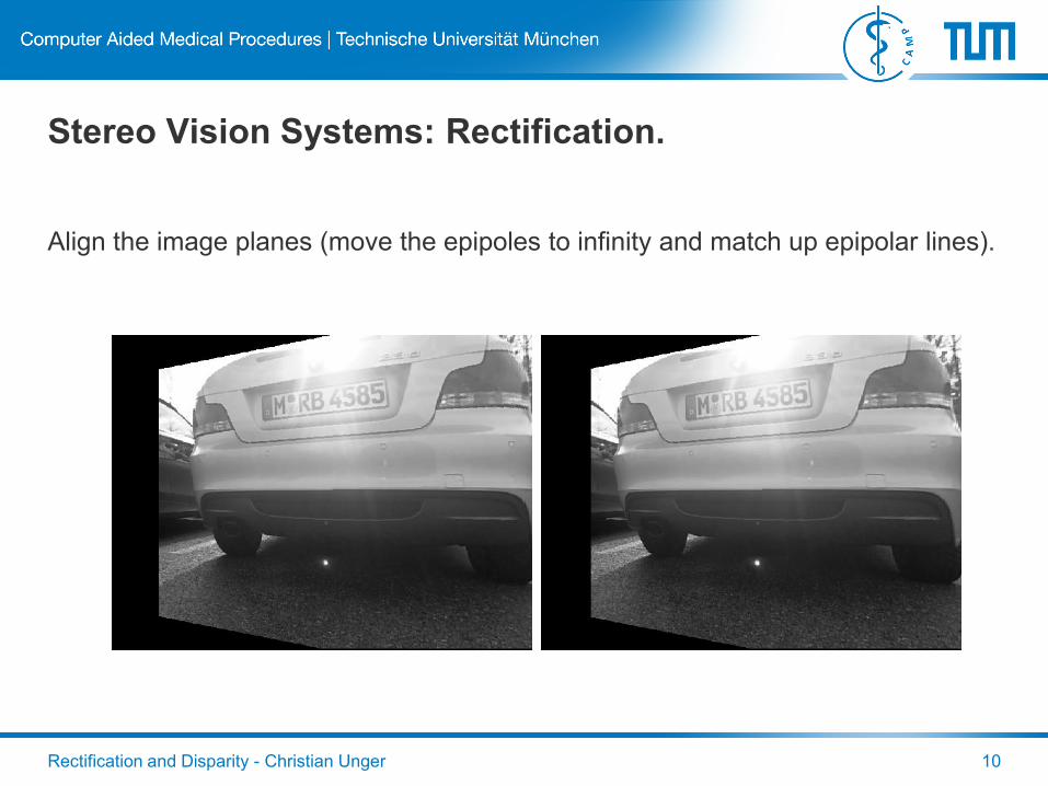
Stereo Vision Systems: Rectification.
Align the image planes (move the epipoles to infinity and match up epipolar lines).
Rectification and Disparity - Christian Unger 11
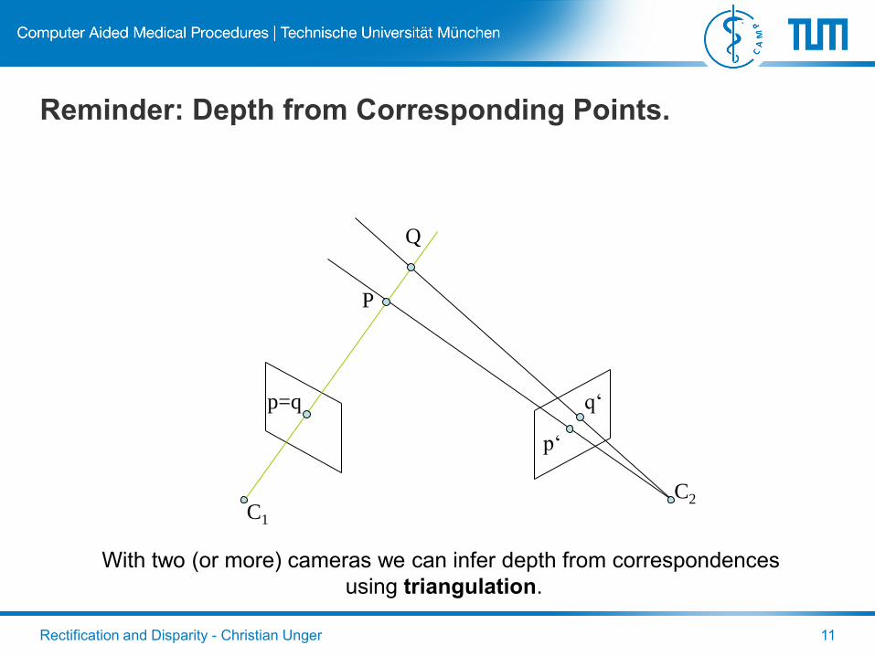
Reminder: Depth from Corresponding Points.
C1
C2
With two (or more) cameras we can infer depth from correspondences
using triangulation.
P
Q
p=q
p‘
q‘
Rectification and Disparity - Christian Unger 12
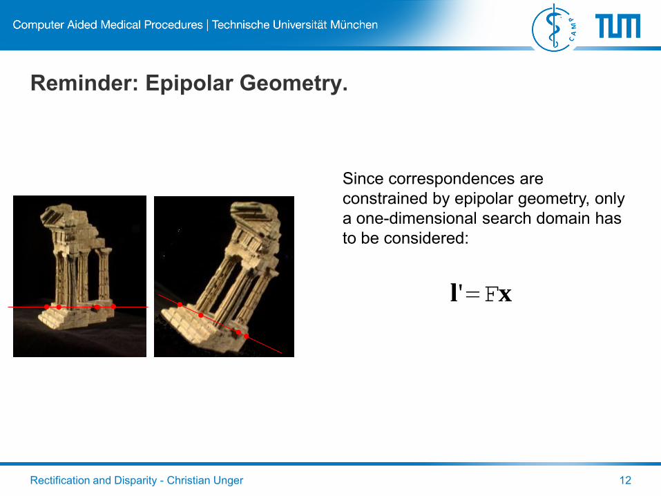
Reminder: Epipolar Geometry.
Since correspondences are
constrained by epipolar geometry, only
a one-dimensional search domain has
to be considered:
xl F'
Rectification and Disparity - Christian Unger 13
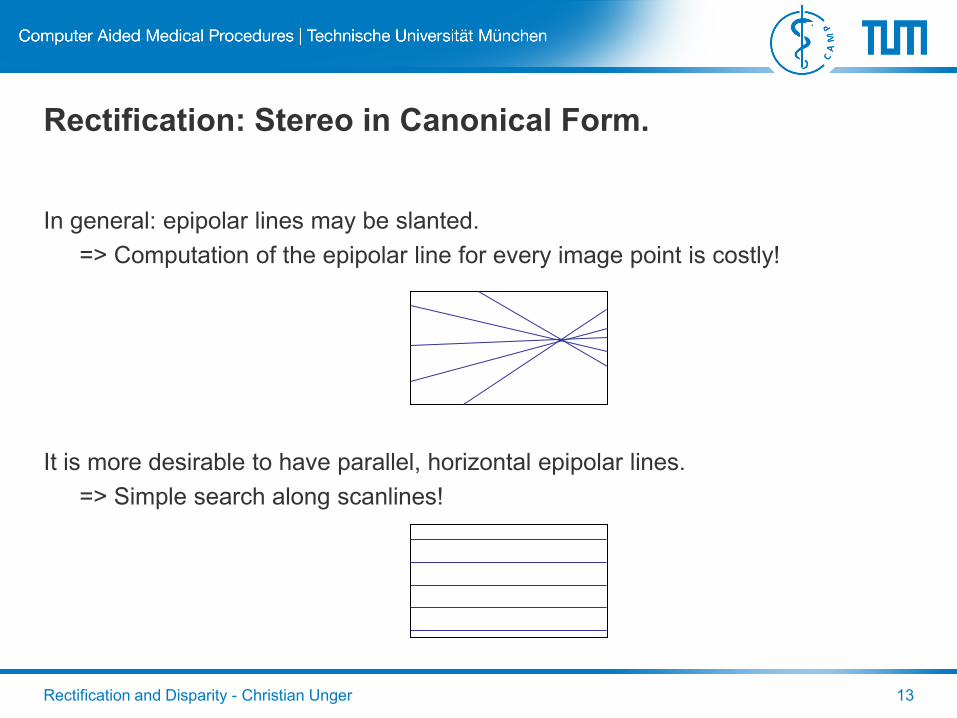
Rectification: Stereo in Canonical Form.
In general: epipolar lines may be slanted.
=> Computation of the epipolar line for every image point is costly!
It is more desirable to have parallel, horizontal epipolar lines.
=> Simple search along scanlines!

Rectification and Disparity - Christian Unger 14
Rectification: Stereo in Canonical Form.
CL
CR
P
p
Epipoles
Rectification and Disparity - Christian Unger 15
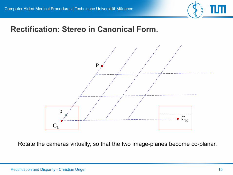
Rectification: Stereo in Canonical Form.
CL
CR
P
p
Rotate the cameras virtually, so that the two image-planes become co-planar.
Rectification and Disparity - Christian Unger 16
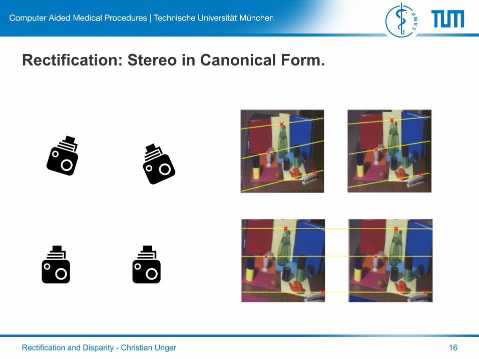
Rectification: Stereo in Canonical Form.
Rectification and Disparity - Christian Unger 17
Rectification: An Interpretation.
In General:
Rectification = Put the epipoles to a predefined position
= Align the image planes (rotation, focal length)
Standard approach:
• Make epipolar lines run parallel to the x-axis. For that,
• move the epipole to infinity and
• match up epipolar lines between views.
By this convention, points will only move in the x-direction – there will be no
movement in y-direction!
Rectification and Disparity - Christian Unger 18
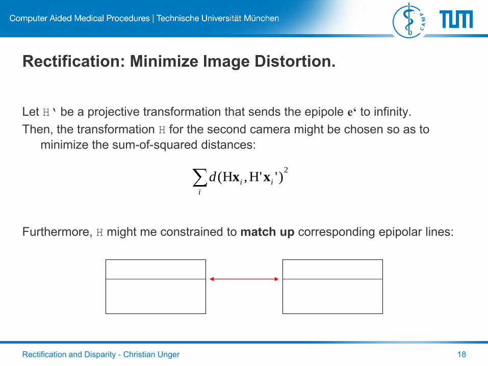
Rectification: Minimize Image Distortion.
Let H‘ be a projective transformation that sends the epipole e‘ to infinity.
Then, the transformation H for the second camera might be chosen so as to
minimize the sum-of-squared distances:
Furthermore, H might me constrained to match up corresponding epipolar lines:
2)''H,H(
i
iid xx
Rectification and Disparity - Christian Unger 19
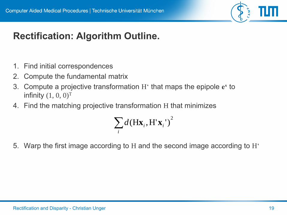
Rectification: Algorithm Outline.
1. Find initial correspondences
2. Compute the fundamental matrix
3. Compute a projective transformation H‘ that maps the epipole e‘ to
infinity (1, 0, 0)T
4. Find the matching projective transformation H that minimizes
5. Warp the first image according to H and the second image according to H‘
2)''H,H(
i
iid xx
Rectification: Another Interpretation.
In practice the presented algorithm (Hartley-Zisserman) works, but may lead to undesireable
results (e.g. „black borders“).
Argumentation via the DOF of a homography:
• Moving the epipole to infinity constrains only 2 DOF.
• Some clarifications and repeatitions:
– Epipolar lines intersect at the epipole.
– The image of the baseline in rectified images is parallel to the x-axis.
• Now, we use four line-to-line correspondences:
– We use 2 epipolar lines to constrain top and bottom image borders
– We use another 2 lines being orthogonal to the baseline to constrain left and right image borders
– These four lines define a rectangle => ensure that the rectangle is completely within the FOV.
Rectification and Disparity - Christian Unger 20
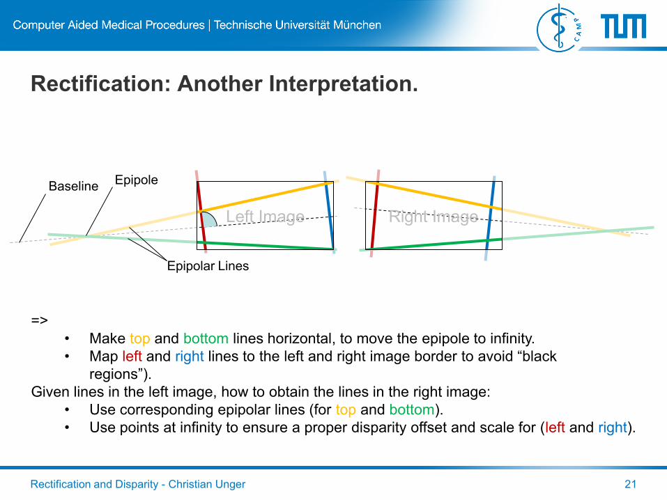
Rectification: Another Interpretation.
Rectification and Disparity - Christian Unger 21
Left Image Right Image
Baseline
Epipolar Lines
Epipole
=>
• Make top and bottom lines horizontal, to move the epipole to infinity.
• Map left and right lines to the left and right image border to avoid “black
regions”).
Given lines in the left image, how to obtain the lines in the right image:
• Use corresponding epipolar lines (for top and bottom).
• Use points at infinity to ensure a proper disparity offset and scale for (left and right).
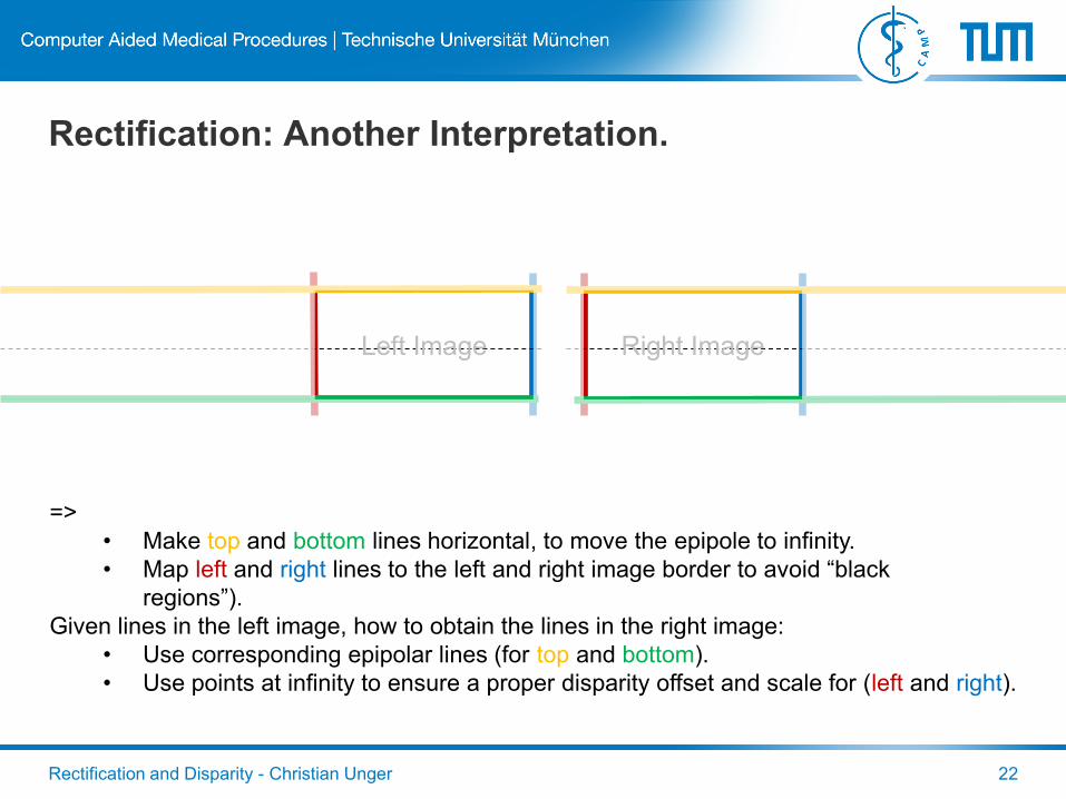
Rectification: Another Interpretation.
Rectification and Disparity - Christian Unger 22
Left Image Right Image
=>
• Make top and bottom lines horizontal, to move the epipole to infinity.
• Map left and right lines to the left and right image border to avoid “black
regions”).
Given lines in the left image, how to obtain the lines in the right image:
• Use corresponding epipolar lines (for top and bottom).
• Use points at infinity to ensure a proper disparity offset and scale for (left and right).
Rectification and Disparity - Christian Unger 23
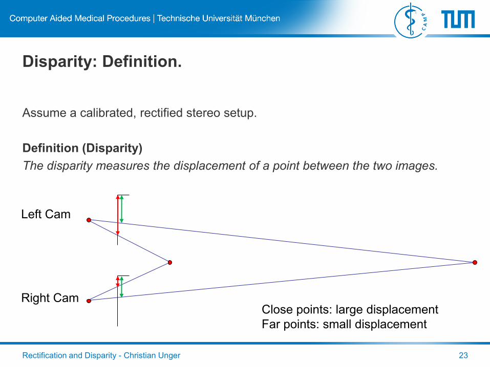
Disparity: Definition.
Assume a calibrated, rectified stereo setup.
Definition (Disparity)
The disparity measures the displacement of a point between the two images.
Left Cam
Right CamClose points: large displacement
Far points: small displacement
Rectification and Disparity - Christian Unger 24
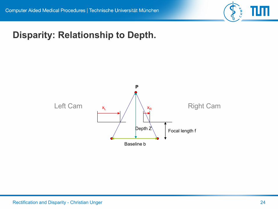
Disparity: Relationship to Depth.
Left Cam Right Cam
Baseline b
xL xR
P
Depth ZFocal length f
Rectification and Disparity - Christian Unger 25
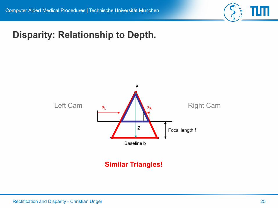
Disparity: Relationship to Depth.
Left Cam Right Cam
Baseline b
xL xR
P
ZFocal length f
Similar Triangles!
Rectification and Disparity - Christian Unger 26
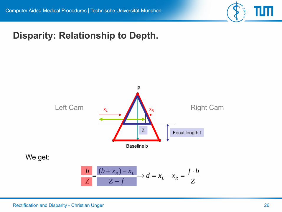
Disparity: Relationship to Depth.
Left Cam Right Cam
Baseline b
xL xR
P
ZFocal length f
We get:
Z
bfxxd
fZ
xxb
Z
bRL
LR )(

Rectification and Disparity - Christian Unger 27
Disparity and the Baseline.
Using this relationship we can draw important conclusions:
• Disparity values are inverse proportional to the depth of a point Z:
– Far points have low disparity (for example the horizon has disparity of zero).
– Close points have a high disparity.
• The disparity is proportional to the baseline b
– The larger the baseline, the higher the disparity.
• The disparity resolution scales linearly with imager resolution:
– High resolutions allow accurate disparity measurements.
Z
fbd
Rectification and Disparity - Christian Unger 28
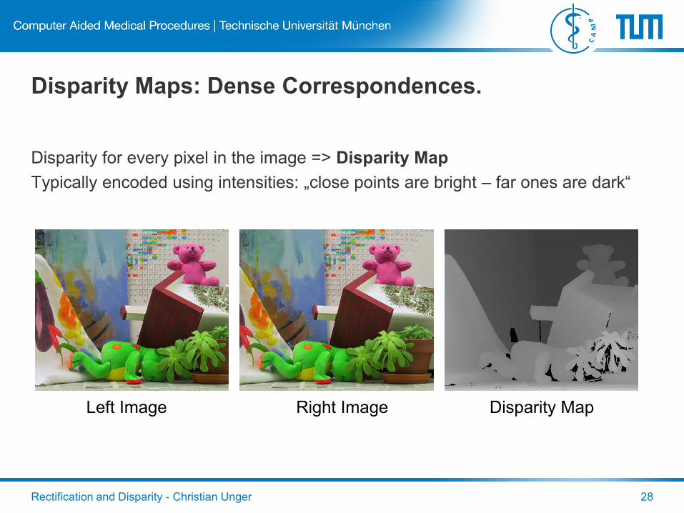
Disparity Maps: Dense Correspondences.
Disparity for every pixel in the image => Disparity Map
Typically encoded using intensities: „close points are bright – far ones are dark“
Left Image Right Image Disparity Map
Rectification and Disparity - Christian Unger 29
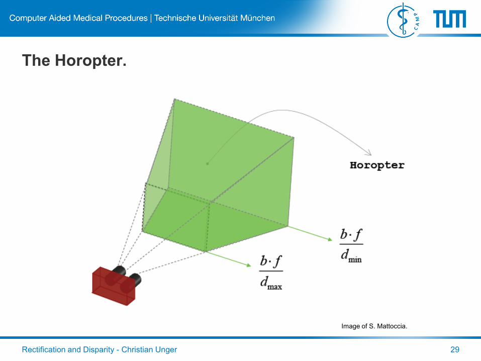
The Horopter.
Image of S. Mattoccia.
Rectification and Disparity - Christian Unger 30
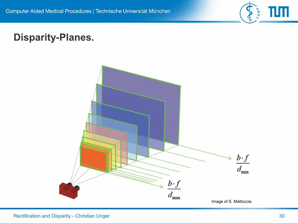
Disparity-Planes.
Image of S. Mattoccia.
Rectification and Disparity - Christian Unger 31
Stereo Vision Systems: Stereo Matching and
Triangulation.
Stereo Matching
Compute a disparity for every pixel of the image.
Next Topic!
Triangulation
Compute the 3D position for every disparity.
Next but one Topic!