RECONSTRUCTION OF DRAWINGS OF THE 32 GUNrichardsmodelboats.webs.com/pdf/Southampton Reconstruction...
22
HMS SOUTHAMPTON NOTES R.Braithwaite Issue 01 NOTES TO ACCOMPANY DRAWINGS OF THE 32 GUN FRIGATE HMS SOUTHAMPTON (BUILT 1757)
Transcript of RECONSTRUCTION OF DRAWINGS OF THE 32 GUNrichardsmodelboats.webs.com/pdf/Southampton Reconstruction...

HMS SOUTHAMPTON NOTES
R.Braithwaite
Issue 01
NOTES TO ACCOMPANY DRAWINGS OF THE
32 GUN FRIGATE
HMS SOUTHAMPTON
(BUILT 1757)

HMS SOUTHAMPTON NOTES
R.Braithwaite Page 2
Issue 01
CONTENTS
1. INTRODUCTION........................................................................................... 3
2. HISTORY ....................................................................................................... 4
3. SAILING REPORTS ...................................................................................... 9
4. DRAWINGS .................................................................................................. 11
4.1. DESIGN DRAUGHT ........................................................................................... 11
4.2. EXTERNAL HULL ............................................................................................. 12
4.3. HULL FRAMING PLAN....................................................................................... 14
4.4. STRUCTURAL SECTIONS ................................................................................... 15
4.5. UPPER DECKS .................................................................................................. 16
4.6. LOWER DECKS ................................................................................................ 17
4.7. PLANKING EXPANSION..................................................................................... 17
4.8. SAIL PLAN ....................................................................................................... 19
5. DRAWING LIST .......................................................................................... 20
6. REFERENCES ............................................................................................. 21
HMS SOUTHAMPTON NOTES
R.Braithwaite Page 3
Issue 01
1. INTRODUCTION
In 1756 the two Navy Board Surveyors each produced an alternative design for a new
class of frigate which would carry 32 12 pounder guns. The Southampton Class,
designed by Thomas Slade was one of these and HMS Southampton is generally
regarded as being the first "true" British frigate. The development of Frigate design
during this period is described in Robert Gardiners Book (Ref.1).
The lines of HMS Southampton have the rounded form characteristic of British mid
18th century fighting ships and show some similarities with the two decker designs (74
and 50 gun) developed by Slade around the same time. The 32 gun frigates were
designed to replace the two deck 44 gun ships and HMS Southampton has a number of
features that were inherited from these ships, which are not seen in subsequent frigate
designs.
Frigate design appears to have been evolving rapidly at the time, and numerous
modifications were made to the Southampton class during its development. This makes
a definitive reconstruction difficult as it is difficult to determine which features made it
through to production. The primary source for this reconstruction is the Southampton
Draught held at the National Maritime Museum. Numerous other sources have had to
be used to develop the drawings. Some of these represent HMS Southampton, herself,
at some stage in her career. Others relate to similar classes of vessels or to more
general information on 18th century shipbuilding practice. I have tried to present the
arguments for using these sources in the notes that follow.
A number of contemporary models exist of the Richmond Class of 32 gun frigates that
were also designed in 1757 (Ref. 2). Unfortunately I have been unable to track down
any models of the Southampton Class. There are, however a number of contemporary
paintings of HMS Southampton which give an indication of her external appearance at
various stages of her career.
I have also included some notes and transcripts relating to the service history and
performance of the ship which I have picked up during my research.
HMS SOUTHAMPTON NOTES
R.Braithwaite Page 4
Issue 01
2. HISTORY
HMS Southampton was launched on 5th May 1757 and served until 1912 when she
was wrecked on a reef in the Cook straight off Barbados. During her long career
HMS Southampton proved to be a very effective fighting ship. Some of the main
events are covered below:
Her First Captain was James Gilchrist who was involved in a number of notable actions
during the Seven Years war the following extracts from his log (Ref. 3) give his
account of events:
26 July 1757 HMS Southampton beat off an attack from french privateers under the
command of the well known commander, Thurot whilst on passage to Plymouth (off
Portland Bill).
“Saw five (?) sail to the Westward at 1/2 past 10. Came up with them. Two ships a
snow and a brigantine all French One of the ships engaged me very warmly for an hour
and a half in which time she received so much damage that she made signal for the
other ship to come down to her assistance who immediately answered her signal by
coming down to her assistance so that I was between two fires, one on the bow and
the other on the quarter. Continued upwards of an hour when luckily I got my whole
broadside to bear on the first ship which silenced her entirely the other ship continued
the engagement for about a quarter of an hour longer when she dropped astern and left
one at this time. I was...... and in no condition to follow either of them.... I put into
Weymouth Road in order to repair my damage in the best manner possible having lost
10 men in the action, 14 mortally wounded and as many more slightly wounded . Most
of my running rigging and sails shot away received a great many dangerous shot soles
betwixt wind and water and her upper works greatly damaged and all the masts greatly
wounded. A shot coming through the Clarks....... great deal of musket..... of the ships
survey.”
13th September 1757 Defeated the 28 gun French frigate “Emeraude” whilst part of
Admiral Boscawen‟s fleet blockading Brest:
“ Light airs and hazy, at 6am saw a sail to the westward in full chase of us. I stood
from her cleared ship and got everything ready for action then tacked and stood for her
at 10....... did not come up with her till 2pm when we began to engage very warmly
and soon fell on board each other when she attempted to through her men into me
which we vigorously disputed for a quarter of an hour but I had the good fortune to
kill both her captains and most of her officers upon which she struck after a very brisk
engagement for 35 minutes. Proved to be a French ship of war called Emeraude
mounting 24 nine pounders and two six pounders and 245 men on board. I lost in the
engagement my second Lt and nineteen men. All my officers wounded except myself
the enemy had 60 killed and wounded. All my lower masts bowsprits and main yard
quite disabled lower shrouds and stays all shot to pieces, lost in the action... by
throwing the... from the forecastle over the enemy anchor stock to keep her to her.
fore sheets main braces fore and mizzen yard tackles larboard fore brace shot away
HMS SOUTHAMPTON NOTES
R.Braithwaite Page 5
Issue 01
starboard quarter cloth tore away by getting foul of the enemy sprit sail shot away. At
3pm got the prisoners on board”
28th March 1759 In action with two French frigates in the North Sea, capturing the 40
gun “La Danae”. James Gilchrist lost an arm during this action:
“Fresh Breezes, Cloudy. At 5 am saw 2 sail in th N.W. out 2 reefs topsails and gave
chase. The Melampe being still in company came first upon them and began about 1/2
past 8 to engage the largest ship. At 9 wore ship to get abreast of her whereby I got in
betwixt her and the Melampe, where I continued during the remainder of the action
being often obliged to back and fill to keep myself in that position . At 1/2 past 11 she
struck and proved to be the Danae, a French man of war of 30x12 pounders
8x6pounders and 2 co‟horrns (?) and had on board 330 men commanded by Mr Barts
loaded with stores and bound for Luebecks (?). I had only one man killed and 8
wounded. I had the misfortune to be one of the latter myself. The hull, masts, yards,
rigging and sails of His Majesties Ship were much wounded and great part of them
shot away. The mizzen staysail and drivers being shot in all parts fell down upon the
decks and were thrown overboard to clear the guns, one of the cutters with masts ,
sails and oars were sunk alongside the..... by her main mast going away. Sent the
Second Lt and 20 men on board the prize.”
June 7th 1761 HMS Southampton took part in the capture of Belleisle under the
command of Captain Charles Antrobus (Ref. 4).
August 9th 1780, in company with Thetis (36) and Ramilles (74) engaged in protecting
a convoy of 63 merchantmen, ran in to the combined Franco-Spanish fleet. 55 of the
merchant ships were lost to the enemy.
June 28th 1781 (Captain Affleck) Action with the French 32 gun frigate La Fee in the
West Indies. Both ships heavily damaged (4 men killed on HMS Southampton, 3 on La
Fee), but the outcome was inconclusive.
1784-1789 Large Repair at ???
1st June 1794 (Capt Forbes) part of Howes fleet on “The Glorious 1st June”
28th July 1781 (Captain MacNamara) captured the French 24 gun ship from under the
guns of Toulon.
Lieutenant Broke's (later Captain of HMS Shannon) Journal 9th June 1796 (Ref.5. )
"Sir J. Jervis discovered a French cruiser working up to Hieres Bay, within the islands,
and immediately singling out the Southampton, called her commander on board the
Victory, pointed the ship out, and directed him to make a dash at her through the
Grand Pass. The Southampton instantly got under weigh and went in, in view of the
entire British fleet, which with anxious suspense witnessed the boldness of an attempt
that scarcely anything but the completest success could have justified. The Admiral
HMS SOUTHAMPTON NOTES
R.Braithwaite Page 6
Issue 01
refused even to give a written order for the enterprise . . . the Southampton pushed
through the Grand Pass, and hauled up under the batteries of the north-east end of
Porquerole, under easy sail, in the hope that she might be mistaken for a neutral or a
French frigate. The stratagem succeeded, and she arrived within pistol shot of the
enemy undiscovered. He (Captain Shield) then cautioned the French Captain through a
trumpet, not to make a fruitless resistance. A shot from a pistol at the speaker, and a
broadside at the Southampton immediately followed. At this instant, being very near
the heavy battery of Fort Braganson, the Southanpton laid the enemy on board; Lieut.
Lydiard, at the head of the boarders, entered and carried her in about ten minutes . . .
about thirty minutes past one in the morning, the Southampton and her prize returned
through the Grand Pass and rejoined the fleet..."
1805-1810 Plymouth Dockyard
3rd February 1812 (Captain Yeo) captured the Ex French 44 gun frigate L‟Amethyste,
manned by Haiian rebels of Port Au Prince. Captain Yeo‟s log is not listed in the
Public record offices collection but James Naval History (Ref.6 gives the following
rather dramatic account:
“On the 2nd of February, as the British 32 gun frigate Southampton, captain James
Yeo, was lying in the harbour of Port-au-Prince, the capital of Petion's dominions in
the island of Saint Domingo, intelligence arrived, that a large frigate, corvette, and a
brig of war, belonging neither to Petion, nor his rival chief Christophe, but to a third
party, formed out of revolters of both, were cruising the south side of the adjacent
island of Guanaboa. Although bound by his instructions to respect the flags of Petiona
and Christophe, Sir James had received no orders to respect any other Haytian flag: he
considered also that, if the squadron was allowed to quit the Bight of Leogane, the
commanding officer would be less scrupulous about the national character, than about
the lading, of the merchant vessels he might fall in with; in short that M. Gaspard, well
known as an experienced privateer's man might feel it to be in his interest to turn
pirate. Those who communicated the information respecting this frigate pointed out, in
reference to Southampton, her superior force, particularly in men, of whom the number
was stated to be upwards of 600. Far from deterring such a man as Sir James Lucas
Yeo, all this stimulated him the more to execute a service which, hazardous as it might
be, a sense of duty taught him was necessary; and accordingly, in the night, the
Southampton weighed her anchor, and proceeded in quest of this formidable frigate
and her two consorts. 6On the 3rd, at six in the morning, having arrived off the south
side of Guanaboa, the Southampton encountered the Amethyste, with corvette and
brig n company. On hailing the Amethyste, Sir James was answered "From Aux-
Cayes" He then sent on board, to request the commander of the frigate to wait upon
him with his papers. Captain Gaspard declined doing this; but sent his first lieutenant
with a paper, purporting to be an order to cruise, and signed, "Borgellat, general-in-
chief of the south of Hayti" Knowing of no authority that this M.Borgellat had to send
armed vessels to sea, sir James replied, that he felt it to be his duty to conduct the
frigate and the two vessels in her company to Port-Royal, Jamaica, that the British
commander-in-chief on the station might determine the validity of M.Borgellat's claim;
and he gave the captain of the Amethyste five minutes to consider the message. A
lieutenant of the Southampton accompanied the Amethyste's first lieutenant back to his
ship, in order to wait the time; but, before three minutes had elapsed, captain Gaspard

HMS SOUTHAMPTON NOTES
R.Braithwaite Page 7
Issue 01
aquatinted the former, that he would rather sink than comply with the demand, but
requested that if the British captain meant to enforce it, he would fire a gun ahead of
the frigate.7As the Southampton's boat pulled round her stern towards the opposite
gangway, the unsuccessful result of the mission was communicated. Off went the bow
gun; and, in another instant, (then just half past six,) the second and remaining guns
upon the broadside of the Southampton followed in rapid succession. The fire was
returned; the action went on; and the Amethyste, aware of what was the chief arm of
her strength, made several efforts to board; but the Southampton, by her superiority in
manoeuvring, frustrated every attempt. It had always been an essential point in sir
James Yeo's system of discipline, to practise his men at gunnery; and they now gave
unequivocal prrof of the proficiency to which they had attained. The main and mizen
masts of the Amethyste fell in quick succession, before the cannonade had lasted half
an hour; and her hull soon became riddled from stem to stern: still the desperate crew
continued a feeble and irregular fire. The Amethyste's two consorts, in the mean time,
had made sail, and were running for shelter under the battery of Maraguana. At about
three quarters past seven, desirous to put an end to whanow could hardly be called a
contest, sir James Yeo hailed to know if the Amethyste (whose colours had been shot
away) had surrendered: some one on board replied in the affirmative; and the
Southampton ceased her fire. Scarcely had she done so, than the fire-mast and
bowsprit of the Amethyste went by the board.7A proof of the inexperience of the
latter's crew, and the confusion into which they had been thrown by the smart and
destructive fire of their antagonist, may be seen in the Southampton's loss; which
amounted to only one seaman killed, and a midshipman and nine seamen and marines
wounded. On the other hand, the Amethyste, out of her crew of 700men (Frenchmen,
Americans, Haytians, a motley group of almost every nation,) had 105 men killed and
120 wounded, including among the latter her captain, M.Gaspard. The whole of the
surviving crew, except about 20 men, were landed at Maraguana, Petite-Goave, and
Port-au-Prince; and the frigate, under jury masts, fitted while she lay in Port-au-Prince,
proceeded, in company with the Southampton, to Port Royal, Jamaica. On a
subsequent day, we believe, the Amethyste was restored to Christophe; and the
conduct of sir James Yeo, in all he had done, was approved.”
The Amethyste was the late french frigate Felicite, captured in June 1809, when armed
en flute, by the british frigate Latona. She was deemed unfit for the british navy, and
sold to an agent of Christophe's to whose little navy she was afterwards attached.
Treachery, or something of the kind, subsequently removed her into the possession of
M.Bougellat; who assumed the command of the department of the south in Saint-
Doningo,upon the death of the revolter Rigaud. The frigates name was then changed
from Amethyste to Heureuse-Reunion; but, in all the accounts respecting her, she is
called Amethyste.
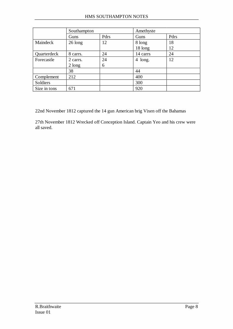
James lists the relative strength of the two vessels as follows:
HMS SOUTHAMPTON NOTES
R.Braithwaite Page 8
Issue 01
Southampton Amethyste
Guns Pdrs Guns Pdrs
Maindeck 26 long 12 8 long 18
18 long 12
Quarterdeck 8 carrs. 24 14 carrs 24
Forecastle 2 carrs. 24 4 long. 12
2 long 6
38 44
Complement 212 400
Soldiers 300
Size in tons 671 920
22nd November 1812 captured the 14 gun American brig Vixen off the Bahamas
27th November 1812 Wrecked off Conception Island. Captain Yeo and his crew were
all saved.
HMS SOUTHAMPTON NOTES
R.Braithwaite Page 9
Issue 01
3. SAILING REPORTS
The following letter from James Glichrist (Ref. 7) shows that he was pleased with the
performance of his new command:
“Southampton Hamoze 29th August 1758
For Southampton
As I know it will be agreeable to you to hear how the Southampton sails after the
addition of her yards, I can now with pleasure inform you it has made a great change
for the better, having seen nothing but what I beat. I had a tryal with the Hussar, which
is reconed a good sailing ship and beat her near a mile an hour, we were both equally
clean. I have been this day with the builder here who inform me there is an order for
lengthening the masts. I am of opinion that the lower masts being lengthened will be of
service but am certain that lengthening of her topmasts will be detrimental as she never
will carry sails.
I am sir your most obedient humble servant Gilchrist
To Thomas Slade Esq.”
More formalised sailing trials were conducted later by the Navy Board (e.g. Ref.8,9)
suggest a ship that was somewhat slower than later frigate designs.
Robert Gardiner‟s review of these reports is as follows:
“Not as fast or as weatherly as contemporary frigate classes in light conditions7-8 kts
close hauled in a topgallant gale to 12 kts before the wind. Better in a blow: of
Southampton it was said “ in reefed topsail weather few or no ships can carry more sail
or keep a better wind”, and would tend to fore-reach under courses alone on ships that
were otherwise superior. However, very manoeuvrable- quick in staying and wearing,
going about in a short distance. Good sea boats, pitching easily in a seaway, and being
very stiff would sail faster in these conditions as more canvas was pressed upon them.
They may have been faster originally: an early report on Vestal claims 9-91/2 knots
close-hauled in a topgallant gale and 14 kts before the wind, but then that was „ when
the bottom was single, but since it has been sheathed, and her sides laden with
topriders and much iron, we have found that she goes less in every point of sailing by a
knot and a half at least”.
Clearly the design was well suited to long patrols away from Dockyard facilities and
for remaining on station through (for example) the severe winter gales encountered on
blockade off Brest. Her manoeuvrability is also cited as on of the deciding factors in
the action with the frigate Amythyste as late as 1812, although some of this may have
been down to the superior training of the crew.

HMS SOUTHAMPTON NOTES
R.Braithwaite Page 10
Issue 01
An analysis of how British frigate design compared to that of the French Navy and
how each was adapted to meet the requirements of their respective Naval strategies at
the time is given Ref. 10

HMS SOUTHAMPTON NOTES
R.Braithwaite Page 11
Issue 01
4. DRAWINGS
4.1. Design Draught
This drawing is based on the original "Southampton Class" design draught held at the
NMM (Ref 11). The draught shows a number of modifications which have been
included in the reconstruction. These are as follows:
Lower deck increased from 124' to 124'3"
Increase in the flare at the bow.
A note on the draught states that copy of was sent to Inwood on April 9th for the
construction of HMS Southampton. It also states that the following further copies
were produced:
HMS Vestal June 2nd
HMS Minerva May 31st
HMS Diana June 16th
Of these copies only the one for HMS Diana still exists in the NMM collection
(Ref.12). A number of further changes can be seen to have been made to the design by
this stage, including:
Increase in the sheer forward.
raising of the quarter galleries and decreasing their height.
It is not clear whether these changes were incorporated for HMS Southampton and
they have not been included in the reconstruction.
The lines were faired from measurements taken off the design draught. Spline curves
were used to define the sheer, maximum breadth and floor sweep curves . The midship
section below, the lower maximum breadth line, was generated from 3 circular arcs,
with a concave rise of floor drawn tangential to the floor (see Figure 1 ). This
construction is described for a 44 gun frigate in Stalkartt‟s book (Ref. 13). Stalkartt,
however, uses a straight line rise of floor tangential to the floor sweep.
The topsides above the upper maximum breadth line were constructed from two
reverse curves as shown in the figure.

HMS SOUTHAMPTON NOTES
R.Braithwaite Page 12
Issue 01
Figure 1 Midship Section Construction
The radii used to construct the midship section were chosen to give a good fit to the
original draught and were as follows:
Floor sweep: 8‟11”
Lower Breadth Sweep 11‟4”
Reconciling Sweep 19‟ 6”
Upper Breadth and Toptimber Sweep: 9‟3”
The sections forward and aft were developed in the same manner as described by
Stalkartt. All the above arc radii remaining constant with the exception of the lower
breadth sweep. Towards the end of the hull less and less of the floor sweep radius is
included. The lower part of the section being made from a spline curve tangential to
the recociling sweep, the floor sweep remain to define the foot of the reconciler.. At
the extreme ends neither the reconciler nor the floor sweep have any function and the
section is made up of a spline curve tangential to the lower breadth sweep at some
point.
The fairing of the extreme ends was achieved by using a series of waterlines and
buttocks
.
The waterlines were drawn parallel to the keel rather than to the design waterline for
simplicity, rather than parallel with the design waterline as shown in the draught.
4.2. External Hull
This drawing represents the hull drawn to the outside of the planking.

HMS SOUTHAMPTON NOTES
R.Braithwaite Page 13
Issue 01
The disposition of the planking, around the midship section, below the main wale is
shown on the Diana draught. The disposition of all the planking along the length of the
hull was derived in conjunction with the Planking Expansion Drawing so as to give a
fair line of planking as viewed in profile, and to avoid the use of stealers.
The NMM collection does not include a builders contract for the Southampton class.
However a contract does exist for the Niger Class (HMS Eolus is named on the
contract) of 32 gun frigates with modifications for HMS Lowestoft (Ref. 14).
The Niger class was designed in 1757 by Thomas Slade as a replacement for the
Southampton class and has very similar dimensions and frame spacing. It is assumed
that this contract represented a development of the contract used for the Southampton
Class. This is supported by the fact that dimensions measured from the Southampton
draught generally agree with this specification.
Thicknesses of hull planking were taken from the Eolus contract (Ref. 14). The
Southampton draught, however, shows a channel wale (which does not feature on
subsequent frigates and is not mentioned in the Eolus contract). This was clearly
another carry over from the two deckers that the new 32 gun frigate class was
designed to replace. This wale was assumed to be made up of two 4” thick planks.
The line of the channel wale on the draught was taken to reflect the moulded
dimensions.
There is no indication of the external decoration on the Southampton Draught.
There are three contemporary pictures of HMS Southampton held in the NMM picture
collection (Refs 15, 16, 17). The reconstruction of the stern gallery is based on two of
these (Refs 15,16) which show a fairly typically shaped stern for a frigate of the
period. The stern carvings are shown with relatively little detail.
The round aft of the lower and upper counters was taken from the Eolus Contract
(which was assumed to refer to the round aft on the level) as was the round up of the
decks. The round up of the top of the windows was already defined by the round up of
the quarter deck and so this was used to define the roundup of the second counter in
such a way that the sides of the windows remain the same length at the side timber as
they are at the centerline as described by Stalkartt. The round aft of the stern (on the
square) above the second counter was derived from the rake at the centerline and the
round aft ( on the square) and up of the second counter rail. This round aft (on the
square) is constant above the second counter, and this results in a reducing round aft
(on the level) from the second counter to the liferails (due to the tumblehome of the
stern). The resulting round aft (on a level) at the liferails agrees well with the value
quoted in the Eolus Contract. The round up of the lower counter was derived using an
arc of the same radius as the second counter rail.
The outline of the taffrail and the quarterpiece were drawn in the stern view to agree
with the appearance in contemporary ship portraits. These place the top of the
quarterpiece lower than implied by the profile view in the deign draught (which
HMS SOUTHAMPTON NOTES
R.Braithwaite Page 14
Issue 01
suggests the quarterpiece and taffrail outline as a single curve with continuous slope).
The Alarm Draught (also by Slade in 1757) also shows only a profile of the quarter
gallery, again with a simplified curve for the taffrail and quaterpiece. A later drawing of
the stern confirms that this outline was a simplification in this case.
The head rails were set up in the three views (and expanded- although this is not
shown in the paperspace view of the model) in the manner described by Stalkartt, using
the profile view shown on the Southampton draught as a starting point. Scantlings
were scaled from the draught, all rails were given a square section. The spread of the
middle and lower rails in plan were chosen to give a concave outline to all three head
timbers as viewed in the body plan.
3 models contemporary models exist of the Richmond class (2 in the NMM and one in
the Science Museum) which show extensive carving of the stern and headrails together
with painted friezes along the upper hull planking. A modern illustration of HMS
Southampton (Ref 18) appears to be based on the design draught with external
decoration based on the Richmond class models, a full female figure is shown for the
figurehead.
The figurehead is only vaguely represented on one of the contemporary pictures
(Ref.16) as a full figure with right arm raised. The hull friezes are absent from all the
pictures supporting Mr Gardiners assertion that contemporary models were often more
elaborately decorated than the actual ships they represented.
4.3. Hull framing Plan
The scantlings of the floors, 1st futtocks, 2nd futtocks, 3rd futtocks and toptimbers
that make up the hull frames were taken from the Eolus contract. These agree well
with the room and space of 27 ½ “ implied by the design draught and leave a gap of 1”
between the filling frame floors and first futtocks. The Eolus contract states “ the
timbers of the frame to be filled in and caulked from the floor heads downwards to the
midships on each side”.
It was not customary to produce framing plans is 1756 and none exists for HMS
Southampton. However a framing plan does exist for the 28 gun frigate HMS Hind
which was built in (Ref. 19 ). HMS Hind belonged the Unicorn class of frigates
originally designed in 1747. Thomas Slade was involved in the development of this
design and the arrangement of the frame joint lines shown on the draught (relative to
the gun ports) is very similar to that on the Southampton Draught.
The main frame bends were constructed of paired frames with joint lines as shown in
the Southampton draught. In between each set of main bends were a pair of single
filling frames. The only exception being amidships where 5 filling frames were fitted
(After HMS Hind). The manner in which the frames are worked around the gunports is
based on the HMS Hind plan for the reasons described above.
The arrangement of the cant frames was taken from the draught of HMS Diana (since
these are not shown on the Southampton Draught). The main cants were assumed to

HMS SOUTHAMPTON NOTES
R.Braithwaite Page 15
Issue 01
be paired (as with HMS Hind) with two intermediate "filling frames" as shown in
Figure 2. The sided dimensions of the cants was taken as constant and to be the same
as the 3rd futtocks and toptimbers, no sizes are given in the Eolus Contract.
Figure 2 Positioning of Cant Frames in Half Breadth Plan
It was not found possible to align all the cant frames with the toptimbers shown in the
Southampton Draught. Some short timbers were, therefore, introduced to enable the
quarterdeck gunports to be properly framed.
The arrangement of transoms was taken from the Diana draught as these are not
shown on the Southampton draught. These are shown parallel to the lower deck and
not with the baseline as was often the case.
The framing of the stern is not shown in the design draught and is based on other
draughts of contemporary frigates (Ref.1). The scantlings of the counter timbers are
not listed in the Eolus contract and were taken as 7”(sided) at the wing transom
tapering to 4” at the taffrail.
The stem was drawn tapering from 1‟5” at the head to 1‟2” below the rabbet as in the
Eolus contract. The Apron was drawn with a constant sided dimension of 1‟9” (as
Eolus) and this siding was continued for the forward deadwood as far as the first
square frame bend. This enabled the knightheads and hawse pieces to be set up parallel
with the keel. The Knightheads and hawsepieces were sided at 1‟2” as described in the
contract. They were reduced by 1” (on each side) away from the boxing to give a
finished siding of 12” for the hawse pieces and 13” for the knightheads. No stemson is
shown in the Southampton draught but one is listed in the Eolus contract. It is assumed
that one was fitted to the actual ship (one is shown on the Draught of the 36 gun
frigate HMS Brilliant of 1757, which was an extended Southampton).
4.4. Structural Sections
This drawing shows a longitudinal section at the centerline looking to port together
with three transverse sections.
Cant joint lines from
Diana draught
Main Bends
Filling frames spaced as
evenly as possible
between main bends

HMS SOUTHAMPTON NOTES
R.Braithwaite Page 16
Issue 01
Keel, false keel and keelson dimensions were taken from the Eolus contract. The rising
wood is not listed and this was drawn as 3” wider than the keel (scored down to the
keel width iwo floors) and 7” deep (?) (being half the depth of the keel as suggested by
P.Goodwin Ref ?).
The Southampton draught shows the early eighteenth century practice of terminating
the keelson on the aft deadwood without the addition of a sternson knee, which
extended the keelson in later vessels to form an additional clamp over the transoms. A
later drawing illustrating an experimental steering system fitted to the ship in 1811
shows a sternson knee (Ref. 20). Presumably this was fitted during one of rebuilds
during Southampton‟s life. The length of the keelson was reduced slightly from that
shown in the Southampton draught to enable the deadwood knee to be drawn in
(terminating under the lowest filling transom).
The scantlings of the internal planking was based on the Eolus contract. However,
there was insufficient room between the thick stuff over the 1st futtock head and the
orlop beams for orlop clamps to be included.
The moulded dimensions of the frames is defined in the Eoulus contract at the head of
each successive timber and this information was used to define the frames in the
transverse sections. The chocks were drawn as 4‟ long based on David Whites
reconstruction of the later 38 gun frigate Diana (Ref. 21)
The camber of the decks and the structural scantlings were taken from ref. 14 the
roundup being taken as across the moulded breadth at the height of the deck at
amidships (or at the midship ends in the case of the quarterdeck and forecastle). The
headroom between decks shown on the Southampton draught agrees with the Eolus
contract except in the case of the forecastle where the headroon is only shown as
around 5'3" rather than the 5'10" as required by the contract. This was increased on the
reconstruction by raising the forecastle deck (as Diana).
The Southampton design draught shows the length of the hanging magazine (combined
magazine and filling room?). This has been drawn with palleting on the magazine deck
framed with 4 ½” timber. The compartment around the foremast has been assumed to
represent the light room.
4.5. Upper Decks
The original deck plan for HMS Southampton (Ref. 22) was used in the
reconstruction. These plans disagree with the design draught in a number of respects
including:
Quarterdeck extends forward of the main mast (included in reconstruction).
Capstan is shown about 1' further forward.
Locations of some deck beams
HMS SOUTHAMPTON NOTES
R.Braithwaite Page 17
Issue 01
The deck beams were located as shown in the design draught (i.e with the capstan in
the same place) and one additional beam was added to the orlop deck to define the
forward end of the main hatch.
The number of tiers of carlings on the upper deck was taken from the Eolus contract.
A deck plan of HMS Boston agrees with the Eolus contract (32 Gun Frigate of
Richmond Class Ref. 23) and serves as a guide for the arrangement of these carlings.
The Eolus contract does not list the scantlings or spacing of the ledges, and these were
taken as 4” broad x 31/2” deep.
The planking of the quarterdeck and forecastle is drawn with tapering planks (around 9
½” wide to 6” approx.). This is the arrangement shown on contemporary models of the
Richmond Class of 32 gun frigates (Ref. 2).
The moulded line of the beakhead bulkhead is shown on the Southampton draught as
being just forward of Station “U”. The beakhead stanchions are shown on the Diana
deck plan (not on the Southampton deck plan, which is somewhat less detailed) and
appear to be approx. 5x5”. These would usually be mounted directly in front of the cat
tail and cat beam, with their lower ends tenoned in to the collar beam. The geometry of
the draught and the Diana deck plan suggest that a 6” timber was placed in front of
the cathead making up the 24” between the aft face of the cathead and the moulded
line of the beakhead bulkhead. None of these timbers are mentioned in the Eolus
contract, because this ship ( and all subsequent frigate designs) were not fitted with
beakhead bulkheads. The toptimber of the forwardmost cant frame is made square with
the keel so as to frame the side of the beakhead bulkhead.
4.6. Lower Decks
The Lower deck framing was based on a combination of the Eolus contract, the
Southampton Deck Plan and the Boston draught as described for the upper deck.
The orlop platforms are shown without any carlings or ledges, as these are not
mentioned in the Eolus contract or shown in the Boston draught. The Southampton
Deck Plan does not show the orlop platforms. However these are shown on a Draught
of the sister ship Diana ( Ref. 24). This shows the arrangement of internal bulkheads
and passageways giving access to the hanging magazine and light room. The width of
the hanging magazine was scaled from this draught and defines the width of the large
aperture in the forward platform. A scuttle was added to give access to the port side of
the light room.
4.7. Planking Expansion
The expansion drawn represents the moulded surface of the hull.

HMS SOUTHAMPTON NOTES
R.Braithwaite Page 18
Issue 01
This surface was expanded using the 2' waterlines (parallel to the keel) and sections.
The girth distances were measured on the sections, between waterlines, and on the
waterlines (between section stations). The bottom shell was expanded from the
moulded rabbet line (parallel to the baseline and 2" below) and the midship section.
This was accomplished by setting up a horizontal line to represent the keel rabbet with
all the station points marked along it. The girths between the waterlines at amidships
were then measured on the body plan and a series of parallel lines were offset from the
keel rabet between station (2) and (B) to give the expansion of the parallel mid body.
The girths from the rabet up to the 2' waterline were then measured for all the other
sections. A circle was then drawn centered on each station marked along the keel rabet
line with a radius equal to this girth measurement. Another circle was then drawn
centerd on the intersection of the expanded 2' wl with station (2) with a radius equal to
the distance measured along the 2' wl between stations (2) and 1. A line was then
drawn between the center of this circle and the intersection of this circle and the circle
centered on keel rabet at station 1 and from this point to the keel rabet at station 1 (see
figurexxx). This process was repeated aft to complete the expansion of the aft hull
between the keel and the 2' waterline. The process was repeated for the other
waterlines up to the 18' waterline. The result of this was a "net" of straight elements
each of which was the correct length to represent the section girths between waterlines
and the expanded waterline between sections. A spline curve was then fitted to
represent the section lines on the expansion. The total length of this spline will differ
slightly from the true section girth but the error is very small (less than 1") and would
not be noticeable at 1:48 scale. Similarly although the widths of the planks will be
correct where they cross the section lines the lengths will be slightly distorted as the
planks will not follow the waterlines. The Topsides were expanded from the top of the
sheerstrake to the bottom of the main wale. The expansion was started by plotting the
intersections of the sheerline with the stations forward and aft of amidships. The x co-
ordinate of each point was taken as the distance measured along the sheerline inn the
half breadth plane from amidships to the station in question. The y co-ordinate was
taken as the vertical height of the sheerline above the height of the sheerline at
midships (as measured on the profile view). The 24',22''20', and 18' waterlines and
sections were then expanded downwards in the same manner as the bottom shell.
Planking disposition. Below whale All the planks are 11.67" wide at amidships. The
width variation for the aft end of the hull below was determined as follows. The
planking was divided into 5 bands of 1,3 ,6,5,10 planks. The proportion of the section
girth taken up by each of these bands was varied by a constant multiplied by the cube
of the distance from amidships (see figure) to give a fair run of planks. For the forward
body the garboard was run at a constant width and the remaining girth between the
rabet and the whale was divided equally between the remaining 24 planks. Wale and
above The profile view on the original draft was used as a guide to the vertical offset
of the moulded seams of the rails and wales. The lower moulded line of the main wale
was altered slightly from that shown in the design draft so as to make it of constant
moulded width (the design draft shows constant projected width. The main wale was
made top and butt planked with the following proportions: Figure A channel wale
was included as shown in the original draft. This was made up of two straight planks.
The sheer rail was made as a full depth plank in order to make it work with the knuckle
in the forward topsides. The lower rail, however was made as a moulding added to the
outside of the planking.

HMS SOUTHAMPTON NOTES
R.Braithwaite Page 19
Issue 01
4.8. Sail Plan
Mast and Spar Dimensions for HMS Southampton are given in reference 25. Steel‟s
Elements and Practice of Rigging and Seamanship has been used for deriving
subsidiary dimensions (Ref. 26.)
Square sails
Dimensions derived from the spar dimensions and from Ref. 26
Fore and aft sails. Generally taken from the proportions given in James Lees Book
(Ref. 27 although adapted to suit Southamptons spar arrangement.
HMS SOUTHAMPTON NOTES
R.Braithwaite Page 20
Issue 01
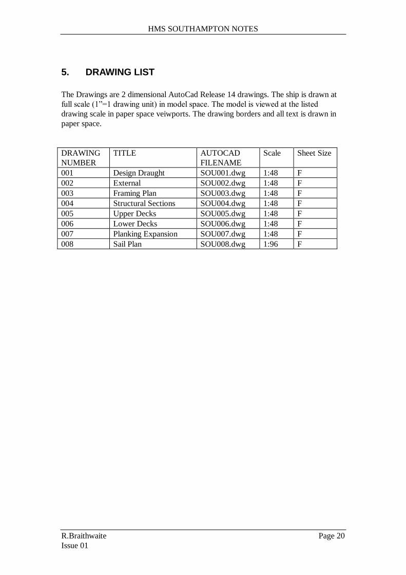
5. DRAWING LIST
The Drawings are 2 dimensional AutoCad Release 14 drawings. The ship is drawn at
full scale (1”=1 drawing unit) in model space. The model is viewed at the listed
drawing scale in paper space veiwports. The drawing borders and all text is drawn in
paper space.
DRAWING
NUMBER
TITLE AUTOCAD
FILENAME
Scale Sheet Size
001 Design Draught SOU001.dwg 1:48 F
002 External SOU002.dwg 1:48 F
003 Framing Plan SOU003.dwg 1:48 F
004 Structural Sections SOU004.dwg 1:48 F
005 Upper Decks SOU005.dwg 1:48 F
006 Lower Decks SOU006.dwg 1:48 F
007 Planking Expansion SOU007.dwg 1:48 F
008 Sail Plan SOU008.dwg 1:96 F
HMS SOUTHAMPTON NOTES
R.Braithwaite Page 21
Issue 01
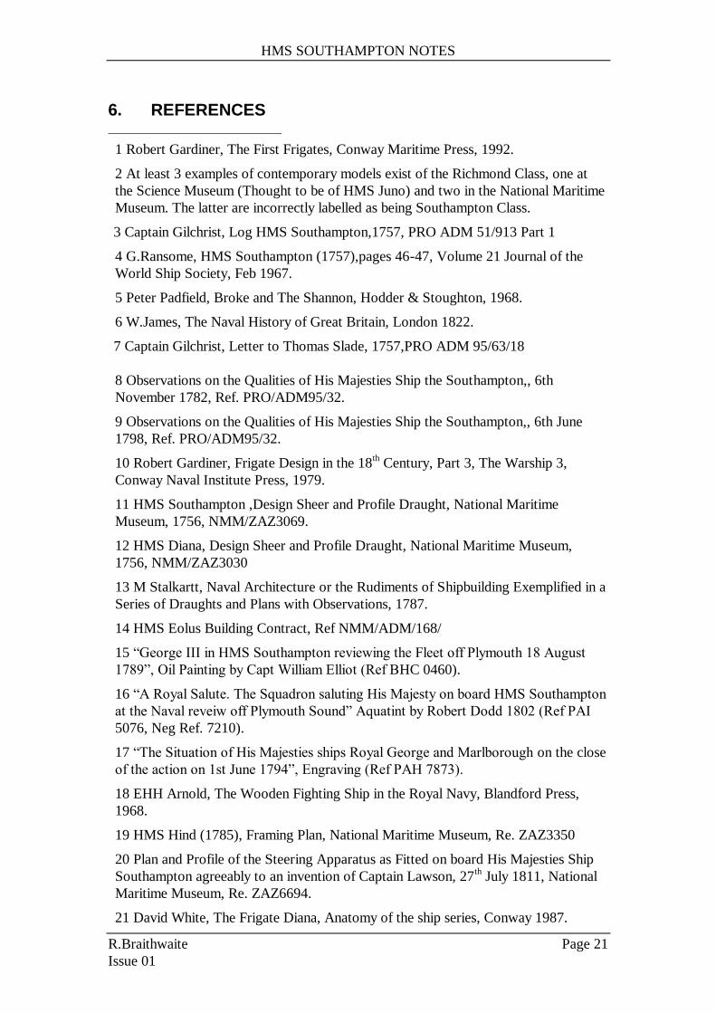
6. REFERENCES
1 Robert Gardiner, The First Frigates, Conway Maritime Press, 1992.
2 At least 3 examples of contemporary models exist of the Richmond Class, one at
the Science Museum (Thought to be of HMS Juno) and two in the National Maritime
Museum. The latter are incorrectly labelled as being Southampton Class.
3 Captain Gilchrist, Log HMS Southampton,1757, PRO ADM 51/913 Part 1
4 G.Ransome, HMS Southampton (1757),pages 46-47, Volume 21 Journal of the
World Ship Society, Feb 1967.
5 Peter Padfield, Broke and The Shannon, Hodder & Stoughton, 1968.
6 W.James, The Naval History of Great Britain, London 1822.
7 Captain Gilchrist, Letter to Thomas Slade, 1757,PRO ADM 95/63/18
8 Observations on the Qualities of His Majesties Ship the Southampton,, 6th
November 1782, Ref. PRO/ADM95/32.
9 Observations on the Qualities of His Majesties Ship the Southampton,, 6th June
1798, Ref. PRO/ADM95/32.
10 Robert Gardiner, Frigate Design in the 18th Century, Part 3, The Warship 3,
Conway Naval Institute Press, 1979.
11 HMS Southampton ,Design Sheer and Profile Draught, National Maritime
Museum, 1756, NMM/ZAZ3069.
12 HMS Diana, Design Sheer and Profile Draught, National Maritime Museum,
1756, NMM/ZAZ3030
13 M Stalkartt, Naval Architecture or the Rudiments of Shipbuilding Exemplified in a
Series of Draughts and Plans with Observations, 1787.
14 HMS Eolus Building Contract, Ref NMM/ADM/168/
15 “George III in HMS Southampton reviewing the Fleet off Plymouth 18 August
1789”, Oil Painting by Capt William Elliot (Ref BHC 0460).
16 “A Royal Salute. The Squadron saluting His Majesty on board HMS Southampton
at the Naval reveiw off Plymouth Sound” Aquatint by Robert Dodd 1802 (Ref PAI
5076, Neg Ref. 7210).
17 “The Situation of His Majesties ships Royal George and Marlborough on the close
of the action on 1st June 1794”, Engraving (Ref PAH 7873).
18 EHH Arnold, The Wooden Fighting Ship in the Royal Navy, Blandford Press,
1968.
19 HMS Hind (1785), Framing Plan, National Maritime Museum, Re. ZAZ3350
20 Plan and Profile of the Steering Apparatus as Fitted on board His Majesties Ship
Southampton agreeably to an invention of Captain Lawson, 27th July 1811, National
Maritime Museum, Re. ZAZ6694.
21 David White, The Frigate Diana, Anatomy of the ship series, Conway 1987.

HMS SOUTHAMPTON NOTES
R.Braithwaite Page 22
Issue 01
22 HMS Southampton Deck Plan National Maritime Museum, Re. ZAZ3070,
Undated.
23 HMS Boston Deck Plan, Reproduced in Robert Gardiners Book.
24 HMS Diana deck plans as taken off at Chatham, January 1774 ,National Maritime
Museum.
25 HMS Southampton Mast and Spar Dimensions, 1758 NMM/POR/A/19
26 The Elements and Practice of Rigging and Seamanship, David Steel, 1798
27 The Masting and Rigging of English Ships of War 1625-1860, James Lees