
Rail Structure Interaction - hewson consulting...• Undertake rail structure interaction analysis...
29
Jeremy Barnes – Associate Director – Hewson Consulting Engineers Nathan Griffiths – Design Engineer – Hewson Consulting Engineers Case Study Modelling and Benefits Rail Structure Interaction
Transcript of Rail Structure Interaction - hewson consulting...• Undertake rail structure interaction analysis...

Jeremy Barnes – Associate Director – Hewson Consulting Engineers
Nathan Griffiths – Design Engineer – Hewson Consulting Engineers
Case Study Modelling and Benefits
Rail Structure Interaction

Introduction
• Development of Rail Fixings • The Need for Rail Structure Interaction • RSI Modelling Issues • Case Study 1 – Jakarta MRT • Case Study 2 – North Wales Viaduct

Development of Rail Fixings
• Historically jointed rail used • Maximum 37m rail lengths • Fishplate joints with gaps left between rails • Rail movement accommodated at joints • No thermal rail stresses built up • Poor ride quality • Problematic for track circuits • Maintenance liability

Development of Rail Fixings
• Continuously Welded Rail Developed • Joints in rails eliminated • Long lengths of rail can be used • Good ride quality • More compatible with track circuits • Low maintenance but more expensive to install • On UK Network most jointed track replaced by
CWR • Thermal stresses built up in the rail

Development of Rail Fixings

The Need for RSI
• CWR designed to resist thermal stresses • Structure movement increases rail stresses • Rail re-distributes traction & braking
The Need for RSI
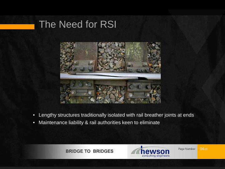
• Lengthy structures traditionally isolated with rail breather joints at ends • Maintenance liability & rail authorities keen to eliminate

The Need for RSI
• Keep spans short and simply supported • May not be the most economic structural solution • Creates a different maintenance liability
The Need for RSI
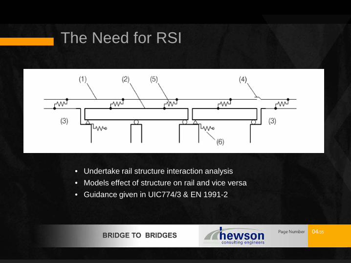
• Undertake rail structure interaction analysis • Models effect of structure on rail and vice versa • Guidance given in UIC774/3 & EN 1991-2

RSI Modelling Issues
• Rail to Structure Connection is non-linear • Represents the build up of resistance and slip of connection • Different frictional values for loaded and unloaded track
0
10
20
30
40
50
60
70
0 0.5 1 1.5 2 2.5 3 3.5 4 4.5 5Resi
stan
ce o
f the
trac
k, k
[kN/
m]s
Displacement [mm]
Ballasted Track Bi-linear Springs
Unloaded
Loaded

RSI Modelling Issues
• Different stiffness values for ballasted and direct fixing • Different frictional values for loaded and unloaded track
0
10
20
30
40
50
60
70
0 1 2 3Resi
stan
ce o
f the
trac
k, k
[kN/
m]s
Displacement [mm]
Bi-linear behaviour of the track
Unloaded [Ballast]
Loaded [Ballast]
Unloaded [Direct Fixing]
Loaded [Direct Fixing]

RSI Modelling Issues
• Long lengths to be modelled to minimize end effects • Abutments, station structures and embankments are stiff elements • Traction and braking forces are attracted to these elements

RSI Modelling Issues
• Limitations on rail curvature in UIC774 & BS EN 1991-2
• Rail curvature limited to 1500m radius • Derogation required in UK to use on curved
track with a radius less than 1500m • Additional lateral restraint required or
reduced allowable stresses

Case Study 1 – Jakarta MRT
• Mass Rapid Transit (MRT) Line in Jakarta, Indonesia • 4.7 km of viaduct decks typically double tracks • 4 elevated stations

Case Study 1 – Jakarta MRT
• Precast segmental internally prestressed • Simply supported spans, typically 36.65m

Case Study 1 – Jakarta MRT
• Direct Fixing track • Fully CWR – no breather joints • UIC 54 rail

Case Study 1 – Jakarta MRT
• 3D Model of rail and viaducts developed • Stiffness of the rail, superstructure, substructure and stations are modelled

Case Study 1 – Jakarta MRT
• Rail stresses
Action Value Permissible stress (UIC)
Temperature +/- 41 N/mm2
72 N/mm2 (Compression)
92 N/mm2 (Tension)
Rail traffic +/- 26 N/mm2
TOTAL +/- 67 N/mm2

Case Study 1 – Jakarta MRT
• RSI – decrease in bearing forces
• More economical bearing
design
0
20
40
60
80
100
120
140
160
180
Typical Bearing
Forc
e [k
N]
Longitudinal bearing forces from railway secondary loads
Without RSI
With RSI

Case Study 2 – North Wales Viaduct
• Single track bi-directional line in North Wales • Significant Rail curvature with track lateral restraints • Low speed line

Case Study 2 – North Wales Viaduct
• Multi-span concrete beam and slab bridge over river • Fully integral piers to eliminate bearings • Thermal movement of piers affects rail stresses

Case Study 2 – North Wales Viaduct
• Fully integral abutments • Sleeved piles at abutments to allow movement • Pway supported on embankment behind

Case Study 2 – North Wales Viaduct
• 3D MIDAS model of rail and structure developed • Rail and structure connected with MIDAS multi-linear springs to model track
bi-linear stiffness relationship • Multi-linear springs at 1m centres

Case Study 2 – North Wales Viaduct
• Stiffness of abutment modelled • Fill resistance behind abutment modelled • Embankment modelled as stiff restraints

Case Study 2 – North Wales Viaduct
• Lower and upperbound models developed to reflect variability in ground conditions
• Lowerbound model included design effects of scour

Case Study 2 – North Wales Viaduct • Rail stresses

Case Study 2 – North Wales Viaduct
• RSI distributes horizontal loads to all piers and to the embankments

Conclusions and Benefits
• RSI analysis opens up the use of multi-span continuous
construction • RSI analysis can allow integral construction to be used • RSI offers economies as longitudinal forces are distributed over
longer lengths reducing the forces on piers and bearings
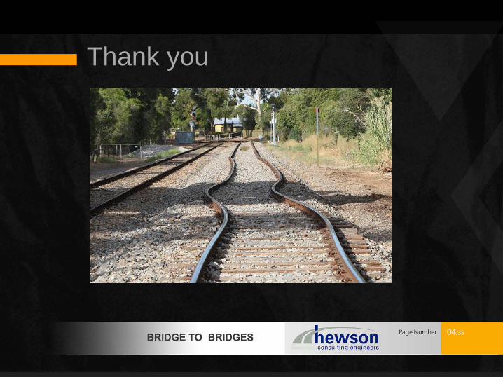
Thank you


