Radio Frequency Generator RFG - WordPress.com...2 Français 1 Operator’s Manual Français VNUS...
19
VNUS ™ Radio Frequency Generator RFGPLUS Model RFG2 Operator’s Manual
Transcript of Radio Frequency Generator RFG - WordPress.com...2 Français 1 Operator’s Manual Français VNUS...

VNUS™
Radio Frequency GeneratorRFGPLUS Model RFG2 Operator’s Manual

en Table of Contents
Introduction . . . . . . . . . . . . . . . . . . . . . . . . . . . . . . . . . . . . . . . . . . . . . . . . . . . . . . . . . . . . . . . 1 Intended Use . . . . . . . . . . . . . . . . . . . . . . . . . . . . . . . . . . . . . . . . . . . . . . . . . . . . . . . . . . . . . . . . . . . 1 General Safety Guidelines . . . . . . . . . . . . . . . . . . . . . . . . . . . . . . . . . . . . . . . . . . . . . . . . . . . . . . . . 1 Precautions/Operation Warnings and Cautions . . . . . . . . . . . . . . . . . . . . . . . . . . . . . . . . . . . . . . . 2 RF Treatment Warnings and Cautions . . . . . . . . . . . . . . . . . . . . . . . . . . . . . . . . . . . . . . . . . . . . . . . 2 Environmental Conditions . . . . . . . . . . . . . . . . . . . . . . . . . . . . . . . . . . . . . . . . . . . . . . . . . . . . . . . . 3 Unpacking and Inspection of Components . . . . . . . . . . . . . . . . . . . . . . . . . . . . . . . . . . . . . . . . . . 3 Setup and Installation . . . . . . . . . . . . . . . . . . . . . . . . . . . . . . . . . . . . . . . . . . . . . . . . . . . . . . . . . . . . 4 Mechanical Specifications . . . . . . . . . . . . . . . . . . . . . . . . . . . . . . . . . . . . . . . . . . . . . . . . . . . . . . . . 4 Equipment Type . . . . . . . . . . . . . . . . . . . . . . . . . . . . . . . . . . . . . . . . . . . . . . . . . . . . . . . . . . . . . . . . . 4
Equipment Description . . . . . . . . . . . . . . . . . . . . . . . . . . . . . . . . . . . . . . . . . . . . . . . . . . . . . . 5 Labeling Symbols . . . . . . . . . . . . . . . . . . . . . . . . . . . . . . . . . . . . . . . . . . . . . . . . . . . . . . . . . . . . . . . 5 Visual Indicators . . . . . . . . . . . . . . . . . . . . . . . . . . . . . . . . . . . . . . . . . . . . . . . . . . . . . . . . . . . . . . . . 6 Audible Indicators . . . . . . . . . . . . . . . . . . . . . . . . . . . . . . . . . . . . . . . . . . . . . . . . . . . . . . . . . . . . . . . 6 Front Panel . . . . . . . . . . . . . . . . . . . . . . . . . . . . . . . . . . . . . . . . . . . . . . . . . . . . . . . . . . . . . . . . . . . . . 7 Rear Panel . . . . . . . . . . . . . . . . . . . . . . . . . . . . . . . . . . . . . . . . . . . . . . . . . . . . . . . . . . . . . . . . . . . . . 8 LCD Screen – ClosureFAST . . . . . . . . . . . . . . . . . . . . . . . . . . . . . . . . . . . . . . . . . . . . . . . . . . . . . . . . . 9 LCD Screen – ClosureRFS . . . . . . . . . . . . . . . . . . . . . . . . . . . . . . . . . . . . . . . . . . . . . . . . . . . . . . . . .10 Gauges – ClosureFAST . . . . . . . . . . . . . . . . . . . . . . . . . . . . . . . . . . . . . . . . . . . . . . . . . . . . . . . . . .11 Gauges – ClosureRFS . . . . . . . . . . . . . . . . . . . . . . . . . . . . . . . . . . . . . . . . . . . . . . . . . . . . . . . . . . . .12
Instructions for Use . . . . . . . . . . . . . . . . . . . . . . . . . . . . . . . . . . . . . . . . . . . . . . . . . . . . . . . . 13 AC Power . . . . . . . . . . . . . . . . . . . . . . . . . . . . . . . . . . . . . . . . . . . . . . . . . . . . . . . . . . . . . . . . . . . . . .13 Changing Settings . . . . . . . . . . . . . . . . . . . . . . . . . . . . . . . . . . . . . . . . . . . . . . . . . . . . . . . . . . . . . .13 Connecting a Device . . . . . . . . . . . . . . . . . . . . . . . . . . . . . . . . . . . . . . . . . . . . . . . . . . . . . . . . . . . .14 Measure Mode . . . . . . . . . . . . . . . . . . . . . . . . . . . . . . . . . . . . . . . . . . . . . . . . . . . . . . . . . . . . . . . . .15 RF Treatment - ClosureFAST . . . . . . . . . . . . . . . . . . . . . . . . . . . . . . . . . . . . . . . . . . . . . . . . . . . . . .16 RF Treatment - ClosureRFS . . . . . . . . . . . . . . . . . . . . . . . . . . . . . . . . . . . . . . . . . . . . . . . . . . . . . . .18 Using MultiMediaCards (MMCs) . . . . . . . . . . . . . . . . . . . . . . . . . . . . . . . . . . . . . . . . . . . . . . . . . .19 Functional and Advisory Limits . . . . . . . . . . . . . . . . . . . . . . . . . . . . . . . . . . . . . . . . . . . . . . . . . . .20
Operating Modes . . . . . . . . . . . . . . . . . . . . . . . . . . . . . . . . . . . . . . . . . . . . . . . . . . . . . . . . . . 21 Power On Self Test (POST) Mode . . . . . . . . . . . . . . . . . . . . . . . . . . . . . . . . . . . . . . . . . . . . . . . . . .21 Identification Mode . . . . . . . . . . . . . . . . . . . . . . . . . . . . . . . . . . . . . . . . . . . . . . . . . . . . . . . . . . . . .21 Measure Mode . . . . . . . . . . . . . . . . . . . . . . . . . . . . . . . . . . . . . . . . . . . . . . . . . . . . . . . . . . . . . . . . .22 Saline Test Mode - ClosureRFS only . . . . . . . . . . . . . . . . . . . . . . . . . . . . . . . . . . . . . . . . . . . . . . . .22 Body Test Mode - ClosureRFS only . . . . . . . . . . . . . . . . . . . . . . . . . . . . . . . . . . . . . . . . . . . . . . . . .23 Alarm Acknowledge Mode . . . . . . . . . . . . . . . . . . . . . . . . . . . . . . . . . . . . . . . . . . . . . . . . . . . . . . .23 Ready Mode - ClosureFAST only . . . . . . . . . . . . . . . . . . . . . . . . . . . . . . . . . . . . . . . . . . . . . . . . . . .23 RF Treatment Mode . . . . . . . . . . . . . . . . . . . . . . . . . . . . . . . . . . . . . . . . . . . . . . . . . . . . . . . . . . . . .23 Error Mode . . . . . . . . . . . . . . . . . . . . . . . . . . . . . . . . . . . . . . . . . . . . . . . . . . . . . . . . . . . . . . . . . . . .24 RFG Setup Mode . . . . . . . . . . . . . . . . . . . . . . . . . . . . . . . . . . . . . . . . . . . . . . . . . . . . . . . . . . . . . . .24 Device Setup Mode . . . . . . . . . . . . . . . . . . . . . . . . . . . . . . . . . . . . . . . . . . . . . . . . . . . . . . . . . . . . .25
Maintenance . . . . . . . . . . . . . . . . . . . . . . . . . . . . . . . . . . . . . . . . . . . . . . . . . . . . . . . . . . . . . . 26 Cleaning and Disinfection . . . . . . . . . . . . . . . . . . . . . . . . . . . . . . . . . . . . . . . . . . . . . . . . . . . . . . .26 Disposal . . . . . . . . . . . . . . . . . . . . . . . . . . . . . . . . . . . . . . . . . . . . . . . . . . . . . . . . . . . . . . . . . . . . . .26
Troubleshooting . . . . . . . . . . . . . . . . . . . . . . . . . . . . . . . . . . . . . . . . . . . . . . . . . . . . . . . . . . . 27 Technical Assistance . . . . . . . . . . . . . . . . . . . . . . . . . . . . . . . . . . . . . . . . . . . . . . . . . . . . . . . . . . . .27 Error Codes . . . . . . . . . . . . . . . . . . . . . . . . . . . . . . . . . . . . . . . . . . . . . . . . . . . . . . . . . . . . . . . . . . . .27 RF Treatment Difficulties . . . . . . . . . . . . . . . . . . . . . . . . . . . . . . . . . . . . . . . . . . . . . . . . . . . . . . . . .27 Electromagnetic Interference (EMI) . . . . . . . . . . . . . . . . . . . . . . . . . . . . . . . . . . . . . . . . . . . . . . .30
Glossary of Terms . . . . . . . . . . . . . . . . . . . . . . . . . . . . . . . . . . . . . . . . . . . . . . . . . . . . . . . . . . 31

2
Français
Operator’s Manual1
Français
VNUS Radio Frequency Generator
Introduction Prior to using the RF Generator, review the warnings and cautions in this manual for important safety information.
The VNUS Radiofrequency Generator (RFGPLUS) is a product of VNUS Medical Technologies, Inc . It is designed to provide controlled delivery of radiofrequency (RF) energy to RF Devices (e .g ., catheters) marketed by VNUS .
The term “Device,” used throughout this manual, refers to compatible VNUS RF Devices that can be attached to the RF Generator .
Please refer to the Instructions for Use included with the RF Device for information related to the Device such as clinical procedures, cautions, warnings, precautions, potential complications, and contraindications.
Intended UseThe VNUS RF Generator model RFG2 is intended for use with radiofrequency devices intended for vessel and tissue coagulation .
The RF Generator measures and displays RF output Power, load Impedance (ClosureRFS only), and elapsed time of RF delivery . The RF Generator also interfaces with a sensor in the Device to provide a continuous display of measured Temperature during RF delivery .
General Safety GuidelinesThe safe and effective use of RF energy is highly dependent on factors under the operator’s control . There is no substitute for properly trained staff . It is important to read, understand, and follow these directions .
The RF Generator is classified as an electrosurgical product . It must be operated in accordance with the safety guidelines described in this section to ensure a safe environment and safe delivery of RF energy to the patient or to the Device . Failure to adhere to these safety guidelines might result in damage to the RF Generator and/or injury to the patient .
The RF Generator is for prescription use only . It is intended for use only by trained clinicians (operators) in a hospital or clinical environment .
Caution: US federal law restricts this device to sale by or on the order of a physician.
The RF Generator contains no operator-serviceable parts . The RF Generator must be either returned to the factory or repaired by qualified service personnel .
Precautions/Operation Warnings and CautionsBefore operating the RF Generator, review and adhere to these guidelines:
• DonotusetheRFGeneratoriftheACPowercordisdamaged. • Inspectallcordsandcablesregularlyforwearordamage.Discontinueuseanddiscardifdamaged. • Donotuse3–to–2pronggroundingadapters. • AlwaysuseanACPowercenter-tapconfigurationfor240VsystemsintheU.S. • DonotoperatetheRFGeneratorincontactwithflammablematerials,chemicals,orsubstances. • ProtecttheRFGeneratorfromexposuretoextrememoisture,suchasrain. • VerifythattheRFGenerator’sventopening,locatedatthebottomoftheunit,isnotobstructed.
Covering the speaker opening might prevent the operator from detecting auditory tones . • DonotremovethecoveroftheRFGenerator.Thereisapotentialforelectricalshock. • Alwaysrefertoauthorizedpersonnelforservice. • AnRFGeneratorfailurecouldresultinanunwantedincreaseinRFPower.
WARNING: The RF Generator produces high voltages on the Device .
RF Treatment Warnings and CautionsBefore performing RF Treatment, review and adhere to these guidelines:
• DANGER,EXPLOSIONHAZARD:Donotuseinthepresenceofaflammableanestheticmixturewithairorwithoxygenornitrousoxide.
• UsetheVNUSRFGeneratoronlywithVNUSClosureFAST or ClosureRFS . DO NOT use with Devices from any other manufacturer with the RFG2 as this may increase the possibility of increased emissions or decreased immunity .
• Avoidcontactofcordsandcableswithpatient,leads,orotherequipment. • DonotwraptheDevicecablearoundmetalobjects,asthismightinducehazardouscurrentsintothe
patient . • Bealertforpotentialinterferencewithpacemakersandotheractiveimplants. • Topreventpatientinjury,alwayschecktodetermineifthemeasuredTemperature,Impedance(not
displayed for ClosureFAST), and RF Power shown in the Data Display area are within safe ranges . • WhileusingtheRFGeneratorduringaprocedure,donotallowthepatienttocomeintodirectcontact
with grounded metal objects . • WhentheRFGeneratorisactivated,theconductedandradiatedelectricalfieldsmightinterferewith
other medical electrical equipment . Refer to the “Electromagnetic Interference (EMI)” section of this manual for more information .
• DonotactivateRFPoweruntiltheDeviceisproperlypositionedinthepatient. • RFPoweractivationtonesandlightsareimportantsafetyfeatures.Donotobstructlights.Donot
disable auditory tones .

4
Français
Operator’s Manual3
Français
VNUS Radio Frequency Generator
Environmental Conditions
Transportation and Storage
During transportation and storage, adhere to these guidelines:
• StoretheRFGeneratorattemperaturesbetween–20°Cand70°Candin non-condensing relative humidity ≤ 90% .
• DonotstackitemsontopoftheRFGenerator. • WhentheRFGeneratorisnotinuse,unplugtheunitfromtheACPoweroutletandwrapthecord
around the AC Power cord wrap area . • DonotcarryorlifttheRFGeneratorbytheACPowercord. • ThechemicalsfromabrokenLCDscreenaretoxicwheningested;handlewithcare,especiallyifthe
LCD screen is broken . If chemicals from a broken LCD screen are accidentally ingested, obtain medical attention immediately .
Operation Conditions for operating the RF Generator include the following:
• Temperaturebetween10ºCand40ºC • Relativehumidity(non-condensing)between0%and90%
Caution: After removing the RF Generator from a storage environment, allow the unit to fully acclimate to the new environment before turning on the unit. Operate the RF Generator only at temperatures between 10°C and 40°C. Operate the RF Generator only in non-condensing humidity conditions.
Unpacking and Inspection of ComponentsUpon receiving the RF Generator, carefully unpack and inspect the items listed below:
• RFGeneratorwithoutphysicaldamagetothefrontorbackpanels,cover,orscreen • Approvedhospital-gradeACPowercordwithoutcracks,frays,oranyvisiblecordorplugdamage • CD-ROMcontainingthisOperator’sManualandtheServiceManual
All damaged items must be repacked and returned to VNUS Customer Service Department with prior approval . See the back of this manual for contact information .
Setup and Installation The RF Generator must be installed and put into service according to the guidance provided in this document to ensure its electromagnetic compatibility. If in doubt, consult VNUS Customer Service or a local distributor.
TheRFGeneratorshouldbeusedonlywithaHospitalGradepowercordandpluggedintoonlygrounded,HospitalGradeACsources.
The VNUS RF Generator can be placed on any stable cart, table, or platform . It is recommended that the cart have conductive wheels and be rated to hold at least 11 .5 kg (25 lbs .) . Refer to facility protocols and local ordinances for more information .
Provide at least 10 to 15 cm (4–6 in .) of space around the sides and top of the RF Generator for air circulationandcooling.Aftercontinuoususeforextendedperiodsoftime,itisnormalforthetopandrear panel to be warm . Do not block vent openings .
Warning: Do not stack any items on top of the RF Generator . Doing so could damage the unit . The RF Generator should not be used adjacent to other equipment . If adjacent or stacked use is necessary, the RF Generator should be observed to verify normal operation in the configuration in which it will be used .
Mechanical Specifications
• Size:38cmx38cmx19cm(15in.x15in.x7.5in.)maximum • Weight:9kg(20lbs.)maximum
Equipment TypeThe Class I RF Generator is designed to work with Type CF, Defibrillator-Proof RF Devices . TheRFGeneratorisdesignedtowithstandanapplicationofanexternaldefibrillatorwhilethe RF Device is in use .

6
Français
Operator’s Manual5
Français
VNUS Radio Frequency Generator
Equipment DescriptionLabeling Symbols There are several symbols and icons used throughout this manual that are used by the RF Generator and its displays . The operator should be familiar with these symbols and their meanings .
Table 1: Data Display Area Symbols and Icons
Ω Ohms (Impedance) Information, Question, or Verification
°C Degrees Celsius (Temperature)
Warning: Consult alarm/advisory message
W Watts (Power) Data Logging Indicator
OR
ClosureFAST icon:RF not actively powered OR
ClosureFAST icon:RF actively powered to cause tissue heating
Table 2: RF Generator Symbols and Icons
AC Power ON Non-IonizingRadiation
AC Power OFF Earth Ground
RF Power ON MMC Card MultiMediaCard (MMC) Slot
RF Power OFF Increment/UP
Attention: Consult accompanying documents Decrement/DOWN
Fuses Patient Isolated
Alternating Current Electrostatic Sensitive Device (referring to MMC card)
Visual IndicatorsThe RF Generator includes the following visual indicators, as depicted in Figure 1:
• AC Power: Indicates when the RF Generator is turned on . • RF Power: Indicates RF Power status by changing color and illumination, as listed in Table 3 .
Table 3: RF Power Button Status
Light Color Status Mode
OFF None RF Power is disabled . Identification or Measure
ON Green RF Power is enabled (ready for use) . Measure
ON Flashing Green
RF Power is enabled, ready for a catheter or button press to activate RF treatment
Ready
ON WhiteRF Power is activated (in use) and currently delivering RF Power .
RF Treatment
Treatment RF Power cannot be enabled until a Device is connected .
Audible IndicatorsThe RF Generator has several audible indicators designed to alert the operator:
• Alarm: Set of three rapid, high-frequency tones . Sound pressure level of alarm tones is > 45dB (procedural tone volume at quietest setting) and > 80dB (procedural tone volume at loudest setting) .
• Informational: Single short, low-frequency tone • Invalid: Single short, low-frequency tone • Power On: Three ascending-scale tones • RF Power On – Treatment: Two descending-scale tones • RF Power On – Alert: Two rapid groups of two high-frequency tones • RF Start: Single, long low-frequency tone • RF Stop: Single, long low-frequency tone • Valid: Single short, high-frequency tone
Each button press produces a valid or invalid tone. If a button fails to sound, this indicates button malfunction. Should a button malfunction, have the unit serviced.

8
Français
Operator’s Manual7
Français
VNUS Radio Frequency Generator
Front Panel
LCD Screen
RF PowerButton andIndicator
Delivery DeviceReceptacle
Increment/UP andDecrement/DOWN Buttons
Soft Key MenuButtons
AC PowerIndicator
Vent Slots
Figure 1: Front Panel
The RF Generator includes the following buttons on its front panel, as depicted in Figure 1:
• SoftKeyMenu:ActivatetheSoftKeyMenusdisplayeddirectlyabovethebuttonsontheLCDdisplay. • Increment/UP(p) and Decrement/DOWN (q): Cycle up or down through the available menu
choices . After selecting a choice, press these buttons to increase, decrease, or toggle the value of that choice .
• RFPower:ActivatesordeactivatesRFPower.
Rear Panel
AC Power Cord Wrap
AC Power Inlet
EquipotentialGrounding Lug
Fuse Holder
MMCSlot
Handle
VentOpenings
Service Port
AC Power Switch
Figure 2: Rear Panel
The RF Generator includes these features, as depicted in Figure 2:
• AC Power Switch: Turns on or off the RF Generator’s AC Power . • AC Power Cord Wrap: When the RF Generator is not in use, unplug the unit from the AC Power
source and wrap the cord around the AC Power cord wrap area . • AC Power Inlet: Connects the AC Power cord to the RF Generator . • Equipotential Grounding Lug: ProvidesapointforanauxiliaryEarthGroundconnection. • Fuse Holder:Includestwo4A/250V,slo-blo,5x20mmfuses. • Handle: The RF Generator has a handle on each side . Use these handles while carrying or lifting the
unit . • MultiMediaCard (MMC) Slot: Accepts a MultiMediaCard that can be used to store procedure data
and to perform software upgrades . • Service Port: The RF Generator includes a port that is used for calibration and repairs . This port is for
use by qualified service personnel only . • Vent Openings: The RF Generator includes vent openings on the rear panel . Do not block these
openings .

10
Français
Operator’s Manual9
Français
VNUS Radio Frequency Generator
LCD Screen – ClosureFAST TheLCDscreenconsistsofthreeareas:theDataDisplayarea,OperatorMessagearea,andSoftKeyMenuarea.
DeviceTemperature
Data LoggingIndicator Timer Device ID
OperatorMessageArea
Data DisplayArea
Soft KeyMenuArea
Progress Meter RF Power
Gauges
Figure 3: ClosureFAST Main Screen
The Data Display area displays information about the RF Generator’s status . Depending on the status of the RF Generator, information in this area changes to show the following items:
• Data Logging Indicator: Indicates that a MultiMediaCard has been inserted and data is being logged .
• Device ID: Indicates type of Device connected to the RF Generator . • Device Temperature: Indicates current Temperature of connected Device . • Gauges: Indicates Temperature and RF Power with an acceptable range shown for Temperature . • Progress Meter: Indicates treatment time remaining • Timer: The timer counts down starting from the selected treatment time . • RF Power: Indicates current RF Power delivered to the Device .
LCD Screen – ClosureRFS
DeviceTemperature
TemperatureSet Point
Data Loggingindicator Timer Device ID
OperatorMessageArea
Data DisplayArea
Soft KeyMenuArea
DeviceImpedance
RF Power
Gauges
Figure 4: ClosureRFS Main Screen
The Data Display area displays information about the RF Generator’s status . Depending on the status of the RF Generator, information in this area changes to show the following items:
• Data Logging Indicator: Indicates that a MultiMediaCard has been inserted and data is being logged .
• Device ID: Indicates type of Device connected to the RF Generator . • Device Impedance: Indicates current Impedance of connected Device • Device Temperature:IndicatescurrentTemperatureofconnectedDevice;itisnotintendedto
measure patient body temperature . • Gauges: Indicates whether Temperature, Impedance, and RF Power are within or outside of preset limits . • Timer: Indicates the amount of time RF Power has been delivered during the current RF Power On
cycle . • RF Power: Indicates current RF Power delivered through the Device .

12
Français
Operator’s Manual11
Français
VNUS Radio Frequency Generator
Gauges – ClosureFAST The RF Generator’s Data Display area includes colored gauges when a Device is connected . These gauges provide a quick and easy way to determine if the Device’s parameters (Temperature and RF Power) are withinacceptableranges.Ifaparameterisnotwithinanexpectedrange,theRFGeneratordisplaysanadvisory message and sounds a tone .
Gauge withinnormal range
Upper AdvisoryLimit violated
Power Gauge with referenceticks at 10, 20, 30 and 40 Watts
OperatorMessage
Area
LowerAdvisoryLimitviolated
Figure 5: ClosureFAST Data Display with Gauges
The position of the Temperature gauge’s needle is based on the current value . It points to one of three colored areas, as described below:
Green: Within normal range
Red: Temperature above Advisory Limit
Blue: Temperature below Advisory Limit
TheextentofilluminationofthePowergaugeisbasedonthecurrentPowervalue.
Green: Within normal range
Red: Power above Advisory Limit
For more information about these Limits, see the “Functional and Advisory Limits” section of this manual .
Gauges – ClosureRFSThe RF Generator’s Data Display area includes colored gauges when a Device is connected and not in Measure Mode . These gauges provide a quick and easy way to determine if the Device’s parameters (Temperature, Impedance, and RF Power) are within acceptable ranges . If a parameter is not within an expectedrange,theRFGeneratordisplaysanadvisorymessageandsoundsatone.
Gauge withinnormal range
Upper AdvisoryLimit violated
Gauge withinnormal range
OperatorMessage
Figure 6: ClosureRFS Data Display with Gauges
The position of the gauge’s needle is based on the current value of the corresponding parameter (Temperature, Impedance, or RF Power) . It points to one of three colored areas, as described below:
• Green: Within normal range • Yellow: Violation of Advisory Limits • Red: Violation of Functional Limits
Red(lower)
Yellow(upper)
Red(upper)
Yellow(lower) Green
Gauge needle
Figure 7: Gauge
For more information about these Limits, see the “Functional and Advisory Limits” section of this manual .
14
Français
Operator’s Manual13
Français
VNUS Radio Frequency Generator
Instructions for Use
To ensure safe RF delivery, it is important to be familiar with how the RF Generator works, how to change desired settings, and how to interpret displays.
AC PowerThe VNUS RF Generator includes an approved hospital-grade AC Power cord .
Prior to each use, inspect the AC Power cord, the AC Power inlet, and the AC Power outlet that the unit plugs into .
To turn on the RF Generator:
1 . Plug the AC Power cord into the AC Power inlet at the back of the unit . 2 . Plug the AC Power cord into a grounded hospital-grade AC Power outlet . 3 . Press the AC Power switch UP to turn on the unit . 4 . Verify the AC Power indicator is lit when the unit turns on . If the indicator is not lit, check the AC Power cord, fuses, and AC Power outlet . 5. Verifyallpixelsontheunit’sLCDscreenilluminatewhitewhenturningontheunit.
Caution: Do not plug the RF Generator into the AC Power outlet if any of its surfaces appear to be cracked or damaged. Do not use the RF Generator if the AC Power cord is damaged. Do not use extension cords and/or adapter plugs.
Changing SettingsThe RF Generator lets the operator change the values of Device and RF Generator settings . The operator should be familiar with how to change setting values:
1 . Use the Soft Key Menu buttons located below the Data Display area to choose the DEVICE SETUP or RFG SETUPSoftKeyMenu.
The Operator Message area displays a sub-menu of settings . TheSoftKeyMenuareadisplaysrelatedSoftKeyMenus: • DEFAULTS:ReturnsallsettingstotheRFGenerator’sfactorydefaults(exceptforDate,Time,and
Language settings) . • SELECT: Indicates the options for the highlighted setting . • EXIT: Returns to the previous screen . 2 . Use the Increment/UP (p) and Decrement/DOWN (q) buttons to highlight a setting . 3 . Press the SELECTSoftKeyMenubuttontoselectthehighlightedsetting. The Operator Message area indicates the value(s) for the highlighted setting .
TheSoftKeyMenuareadisplaysrelatedSoftKeyMenus: • DEFAULT:Restorestheselectedsettingtothefactorydefaultvalue(exceptforDate,Time,and
Language settings) . • ACCEPT: Saves the setting’s value(s) as the default value(s) . • CANCEL: Cancels the selection and returns to the previous screen . 4 . Use the Increment/UP (p) and Decrement/DOWN (q) buttons to increment, decrement, or
toggle the value(s) of the selected setting . 5 . Press the ACCEPTSoftKeyMenubuttontosavethechoiceasadefaultsettingorpresstheCANCEL
SoftKeyMenubuttontoreturntothepreviousscreenwithoutsavinganychanges. 6 . After changing the desired setting(s), press the EXITSoftKeyMenubuttontoreturntotheRF
Generator screen .
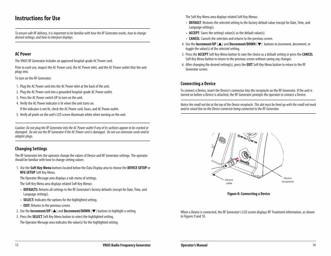
Connecting a DeviceTo connect a Device, insert the Device’s connector into the receptacle on the RF Generator . If the unit is turned on before a Device is attached, the RF Generator prompts the operator to connect a Device .
Notice the small red dot at the top of the Device receptacle. This dot must be lined up with the small red mark and/or raised line on the Device connector being connected to the RF Generator.
Deviceconnector
Devicecable
Devicereceptacle
Figure 8: Connecting a Device
When a Device is connected, the RF Generator’s LCD screen displays RF Treatment information, as shown in Figures 9 and 10 .

16
Français
Operator’s Manual15
Français
VNUS Radio Frequency Generator
Measure Mode
RF PowerDeviceTemperature
Data LoggingIndicator Timer Device ID
Soft KeyMenu Area
Figure 9: ClosureFAST Measure Mode
RF PowerDeviceTemperature
DeviceImpedance
Data LoggingIndicator Timer Device ID
Soft KeyMenu Area
Figure 10: ClosureRFS Measure Mode
RF Treatment - ClosureFAST
WARNING: Review this section and the “General Safety Guidelines” section of this manual before starting RF Treatment .
Before starting RF Treatment, review the Device’s Instructions For Use . Confirm that the connected Device matches the Device ID shown in the Data Display area .
Entering Ready ModePress the RF Power button to enter Ready Mode . The RF Power button will change from non-illuminated to flashing green illumination .
Initiating RF TreatmentPress the START RF button or the Device handle button to start RF Treatment . While delivering RF Power, the RF Power button illuminates white . The Device will increase to the set temperature and hold at that temperature until the treatment time has completed . After the treatment time has counted downtozero,RFPowerdeliverywillstopautomaticallyandtheRF Power button will change to flashing green illumination to indicate Ready Mode . Pressing the START RF button or the Device handle buttonwillstartthenextRFTreatment.
WARNING: Do not activate RF Power until the Device is properly positioned in the patient . Refer to the “General Safety Guidelines” section of this manual before starting RF Treatment .
Data LoggingIndicator Countdown Timer Device ID
Soft KeyMenu
GaugesduringRFTreatmentMode
OperatorMessageArea
Figure 11: ClosureFAST RF Treatment Started

18
Français
Operator’s Manual17
Français
VNUS Radio Frequency Generator
Temperature and Impedance must be within Functional Limits before RF Treatment can start. This temperature display is not intended to measure patient temperature but reflects Device temperature within a relative range.
Halting RF TreatmentDuring RF Delivery, press the STOP RF button or the Device handle button to halt RF Treatment (pressing the RF Power button will also halt RF Treatment and disable Ready mode) .
RF Treatment halts automatically if: • ThetimesetforRFTreatmenthaselapsed(forDeviceswhereRFTreatmenttimecanbeset). • AFunctionalLimithasbeenviolated. • TheRFGeneratordetectsanerror. • TheDeviceisdisconnected.
WARNING: If RF Treatment does not halt automatically, disconnect the Device .
Restarting RF TreatmentThe operator should correct any alarm condition before restarting RF Treatment . (See the “RF Treatment Difficulties” section of this manual for more information .)
If the operator unplugs a Device and then reconnects a Device of the same model, the unit prompts the operator to either retain or discard the Timer Value . Press the YES or NOSoftKeyMenubuttontoretainor discard, respectively, the sum of all times from all previous RF Power On cycles .
Iftheunithasbeenturnedoff,anewTimerValuewillstartwiththetimeresettozero(0:00)whentheunit is turned on again .
The Total Treatment Time displays in the Operator Message area immediately after RF Power halts.
RF Treatment - ClosureRFS WARNING: Review this section and the “General Safety Guidelines” section of this manual before starting RF Treatment .
Before starting RF Treatment, review the Device’s Instructions For Use . Confirm that the connected Device matches the Device ID shown in the Data Display area .
It is also highly recommended that the operator perform the optional Saline and Body Tests . These tests verify the Temperature and Impedance measurements of the Device . For information on performing the Saline Test and Body Test, refer to the “Saline Test Mode” and “Body Test Mode” sections of this manual .
When the RF Generator and connected Device are ready to start RF Treatment, the RF Power button illuminates green . This indicates that Temperature and Impedance measurements are within the Functional range for the connected Device, and RF Treatment can start .
Temperature and Impedance must be within Functional Limits before RF Treatment can start.
Initiating RF TreatmentPress the RF Power button to start RF Treatment . While delivering RF Power, the RF Power button illuminates white . The Device will increase to the set temperature and hold at that temperature until the RF Treatment is halted .
WARNING: Do not activate RF Power until the Device is properly positioned in the patient . Refer to the “General Safety Guidelines” section of this manual before starting RF Treatment .
Data LoggingIndicator Timer Device ID
GaugesduringSaline Testand RFTreatmentModes
OperatorMessageArea Soft Key
MenuCommands
Figure 12: ClosureRFS RF Treatment Started

20
Français
Operator’s Manual19
Français
VNUS Radio Frequency Generator
Halting RF TreatmentDuring RF Delivery, press the RF Power button to halt RF Treatment .
RF Treatment halts automatically if:
• AFunctionalLimithasbeenviolated. • TheRFGeneratordetectsanerror. • TheDeviceisdisconnected.
Restarting RF TreatmentThe operator should correct any alarm condition before restarting RF Treatment . See the “RF Treatment Difficulties” section of this manual for information .
If the operator unplugs a Device and then reconnects a Device of the same model, the unit prompts the operator to either retain or discard the Timer Value . Press the YES or NOSoftKeyMenubuttontoretainor discard, respectively, the sum of all times from all previous RF Power On cycles .
Iftheunithasbeenturnedoff,anewTimerValuewillstartwiththetimeresettozero(0:00)whentheunit is turned on again .
The Total Treatment Time displays in the Operator Message area immediately after RF Power halts.
Using MultiMediaCardsMultiMediaCards (MMCs) can store data from recent procedures, log generator errors, and perform software updates . The operator must use VNUS part number MMC .
WARNING: Proper ESD precautionary procedures should be used when handling, inserting, or removing the MMC card .
Before handling the MMC card, touch the metal frame of the RFG2 to discharge any static electricity . Alternatively, you may use an ESD wrist strap to bond yourself to the RFG2 or to earth . This is important to avoid electrostatic discharge damage to the MMC card .
AllpersonnelwhohandletheMMCcardshouldreceiveanexplanationoftheESDwarningsymbolandtraining in ESD precautionary procedures . This includes clinical/biomedical engineering and health-care staff . At minimum, this training should include:
• an introduction to the physics of electrostatic charge • the voltage levels that can occur in normal practice • the damage that can be done to electronic components if equipment are touched by an operator
who is electrostatically charged • methods to prevent build-up of electrostatic charge, • how and why to discharge one’s body to earth or to the frame of the RFG2, or bond oneself by means
of a wrist strap to the RFG2 or to earth prior to handling the MMC card
Functional and Advisory LimitsWhile a Device is connected, the RF Generator monitors the Device’s parameters (Temperature, Impedance, and RF Power) . Parameters must be within Functional Limits before RF Treatment can start . The Limits are determined by predefined settings for the connected Device . Advisory Limits are within the range of Functional Limits .
WARNING: Operation of the RF Generator below these values may cause inaccurate results . The RF Generator will not allow treatment if measurements persist outside of these limits .
The limits can also be affected by Set Points that the operator defines in the Device Setup menu . See the “Device Setup Mode” section of this manual for information about defining Set Points .
Functional LimitsFunctional limits for ClosureFAST:
• PatientTemperature:10°Cto130°C
Functional limits for ClosureRFS:
• PatientTemperature:10°Cto110°C • DeviceImpedanceinTreatment,Saline,orBodyTestModes:25-1000Ω • DeviceImpedanceinMeasureMode:≥10Ω
If the RF Generator detects that a parameter violates Functional Limits, the gauge displays within the red range . The unit also:
• HaltsRFTreatment. • SoundsanAlarmTone(forTemperatureorRFPowerparameters)orsoundsanInformationalTone
(for the Impedance parameter) . • EntersAlarmAcknowledgeMode. • DisplaysanAlarmMessage.
Advisory Limits - ClosureFASTDuring RF treatment:
• Ifthesettemperatureisnotreachedwithinapredeterminedtime,RFpowerwillbestoppedbeforethe countdown has completed . This indicates a condition of poor contact between the Device and the tissue to be treated .
• IftheRFGeneratordetectsthattemperatureisbelowtheAdvisoryLimit,thegaugedisplayswithinthe blue range . The unit sounds an Informational Tone and displays a message .
Advisory Limits - ClosureRFSIf the RF Generator detects that a parameter violates Advisory Limits, the gauge displays within the yellow range . The unit sounds an Informational Tone and displays a message .
22
Français
Operator’s Manual21
Français
VNUS Radio Frequency Generator
Operating ModesThe RF Generator has several operating modes . The operator must pay special attention to the Data Display area and Operator Message area during the Body Test, Saline Test, Measure, and RF Treatment modes, in which some level of RF Power is delivered .
Failure during any operating mode results in the RF Generator either not starting RF Treatment or automatically halting RF Treatment.
Power On Self Test (POST) ModeDuring the Power On Self Test (POST), the RF Generator performs a number of internal self-tests of its software:
• Verifiesintegrityofsystemrandomaccessmemory(RAM). • Verifiescontentsofprogramread-onlymemory(ROM). • Activatesallvisualindicators,includingtheLCDscreenandthebacklitSoftKeyMenubuttonsaround
the screen . • SoundsPowerOntone. • Verifiesoperationofradiofrequency(RF)generationandmeasurementcircuits. • DisplaysanoticeifPOSTmustrestorethefactorydefaultsettingsduetoacorruptionofpersistent
settings, such as screen brightness or tone volume settings .
Prior to using the RF Generator, observe that the screen, lights, and audible alarms cycle .
Caution: The RF Generator enters Error Mode if it detects a failure during the Power On Self Test (POST) Mode. If any error messages occur indicating that the RF Generator is not safe to use, power off the unit and contact VNUS Customer Service.
Identification ModeDuring Identification Mode, the RF Generator checks for a connected Device:
• IfnoDeviceisconnected,theOperatorMessageareaaskstheoperatorto“Pleaseconnectdevice.” • IftheconnectedDeviceisunsupported,theOperatorMessageareasays,“Theconnecteddeviceis
unsupported . Please connect another device .” • IftheconnectedDeviceisunknownorinvalid,theOperatorMessageareasays,“Thedeviceisinvalid.”
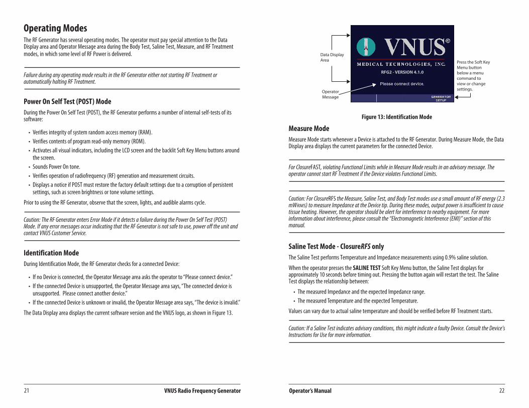
The Data Display area displays the current software version and the VNUS logo, as shown in Figure 13 .
RFG2 - VERSION 4.1.0
Data DisplayArea
OperatorMessage
Press the Soft KeyMenu buttonbelow a menucommand toview or changesettings.
Figure 13: Identification Mode
Measure ModeMeasure Mode starts whenever a Device is attached to the RF Generator . During Measure Mode, the Data Display area displays the current parameters for the connected Device .
For ClosureFAST, violating Functional Limits while in Measure Mode results in an advisory message. The operator cannot start RF Treatment if the Device violates Functional Limits.
Caution: For ClosureRFS the Measure, Saline Test, and Body Test modes use a small amount of RF energy (2.3 mWRMS) to measure Impedance at the Device tip. During these modes, output power is insufficient to cause tissue heating. However, the operator should be alert for interference to nearby equipment. For more information about interference, please consult the “Electromagnetic Interference (EMI)” section of this manual.
Saline Test Mode - ClosureRFS onlyThe Saline Test performs Temperature and Impedance measurements using 0 .9% saline solution .
When the operator presses the SALINE TESTSoftKeyMenubutton,theSalineTestdisplaysforapproximately10secondsbeforetimingout.Pressingthebuttonagainwillrestartthetest.TheSalineTest displays the relationship between:
• ThemeasuredImpedanceandtheexpectedImpedancerange. • ThemeasuredTemperatureandtheexpectedTemperature.
Values can vary due to actual saline temperature and should be verified before RF Treatment starts .
Caution: If a Saline Test indicates advisory conditions, this might indicate a faulty Device. Consult the Device’s Instructions for Use for more information.

24
Français
Operator’s Manual23
Français
VNUS Radio Frequency Generator
Body Test Mode - ClosureRFS onlyThe Body Test performs Temperature and Impedance measurements using the Device positioned in the patient for RF Treatment .
When the operator presses the BODY TESTSoftKeyMenubutton,theBodyTestdisplaysforapproximately15secondsbeforetimingout.Pressingthebuttonagainwillrestartthetest.TheBodyTest displays the relationship between:
• ThemeasuredImpedanceandtheexpectedImpedancerange. • ThemeasuredTemperatureandtheexpectedTemperaturerange.
When the Body Test has completed, the most recent Temperature and Impedance measurements display in the Operator Message area .
Caution: If a Body Test indicates advisory conditions, this might indicate a faulty Device. Consult the Device’s Instructions for Use for more information.
Alarm Acknowledge ModeThe Alarm Acknowledge Mode starts when RF Treatment halts due to an alarm or unrecoverable error . See the “RF Treatment Difficulties” section of this manual for information about unrecoverable errors . To end the Alarm Acknowledge Mode, press the OKSoftKeyMenubuttonorwait30secondsforthemodeto complete .
Once the Alarm Acknowledge Mode has completed, the RF Generator enters Measure Mode if a Device is connected or Identification Mode if a Device is not connected .
Ready Mode - ClosureFAST onlyReady Mode starts after a ClosureFAST Device is attached to the RF Generator and the RF Power button is depressed as prompted on the screen . During Ready Mode, the Data Display area displays the current parameters for the connected Device . During Ready Mode, the RF Generator is enabled and will deliver RF power when the START RF button or the Device handle button is pressed .
RF Treatment ModeDuring the RF Treatment Mode, the RF Generator delivers RF Power . The RF Treatment Mode becomes active when the following are true:
ClosureFast: • TemperatureandImpedancemeasurementsarewithinFunctionalrangefortheconnectedDevice. • TheRF Power button has been pressed to enter ready mode . • TheoperatorpressestheSTART RF button or the Device handle button (note that if body
temperaturehasnotbeenmeasured,analertwilldisplay;thisalertcanbeclearedbypressingOK to proceed) .
ClosureRFS: • TheoperatorpressestheRF Power button .
When RF Treatment has completed, the RF Generator enters Measure Mode or Alarm Acknowledge Mode . For more information about RF Treatment, read the “RF Treatment” sections of this manual .
Error ModeError messages display when the RF Generator encounters an unrecoverable (unable to continue) error .
The Error Mode becomes active and an error code or message displays if any of the following occurs:
• TheRFGeneratordetectsanunexpectedinternalerror. • ThePowerOnSelfTest(POST)fails.
When the Error Mode occurs, RF Treatment halts immediately and the RF Generator logs an entry in the Error Log .
When an error message indicates a non-recoverable error has occurred, turn off the unit, wait a few seconds, and then turn on the unit .
If an error persists, make a note of it and then contact VNUS Customer Service or a local distributor .
RFG Setup ModeThe RFG Setup menu provides a list of settings for the RF Generator . When the operator presses the RFG SETUPSoftKeyMenubutton,theOperatorMessageareadisplaysthesettingsavailablefortheRFGenerator .
To change a setting’s value(s):
1 . Press the RFG SETUPSoftKeyMenubuttontodisplaytheRFGSetupsettings. 2 . Use the Increment/UP (p) and Decrement/DOWN (q) button to highlight a setting . 3 . Press the SELECTSoftKeyMenubuttontoselectthehighlightedsetting. 4 . Use the Increment/UP (p) and Decrement/DOWN (q) button to cycle through the values until
the desired value displays . 5 . Press the ACCEPTSoftKeyMenubuttontoacceptthechange. 6 . Press the EXITSoftKeyMenubuttontoreturntotheRFGeneratorscreen.
Proc Tone VolThe Proc Tone Vol setting adjusts the Procedural Tone Volume from 2 (quietest) to 10 (loudest) The Procedural Tone Volume controls the volume of alarm tones and tones associated with RF Power delivery, such as RF Power start and stop tones . When the volume setting is increased or decreased, a single tone sounds to denote the change .
The operator is prevented from adjusting the Procedural Tone Volume to be quieter than the Informational Tone Volume. If the operator adjusts the Procedural Tone Volume to be equal to or less than the Informational Tone Volume, the Informational Tone Volume automatically adjusts to one level lower than the Procedural Tone Volume.
Info Tone VolThe Info Tone Vol setting adjusts the Informational Tone Volume from 1 (quietest) to 9 (loudest) . The Informational Tone Volume controls the volume of button acknowledgement tones and informational tones . When the volume setting is increased or decreased, a single tone sounds to denote the change .

26
Français
Operator’s Manual25
Français
VNUS Radio Frequency Generator
Gauges - ClosureRFS onlyThe Gauges setting adjusts the Parameter Range Indication gauges as either ON or OFF .
BrightnessThe Brightness setting adjusts screen Brightness from 1 (dimmest) to 10 (brightest) .
LanguageThe Language setting selects the Language displayed on the RF Generator’s screen . The default language is English .
The operator can change the default language from the RFG Setup Mode . The operator can also change the language during the Power On Self Test (POST) Mode:
1 . Press the AC Power switch UP to turn on the unit . 2 . When the Power On Self Test (POST) starts, simultaneously press the first two (starting at left)
SoftKeyMenubuttons. 3. Changethesetting’svalueusingtheSoftKeyMenubuttonsandtheIncrement/UP (p) and
Decrement/DOWN (q) buttons .Date
The Date setting adjusts the current Date .
TimeThe Time setting adjusts the current Time .
Device Setup ModeThe Device Setup menu provides a list of settings for the connected Device . When the operator presses the DEVICE SETUPSoftKeyMenubutton,theOperatorMessageareadisplayssettingsfortheconnectedDevice .
To change a setting’s value(s):
1 . Press the DEVICE SETUPSoftKeyMenubuttontodisplaytheDeviceSetupsettings. 2 . Use the Increment/UP (p) and Decrement/DOWN (q) button to highlight a setting . 3 . Press the SELECTSoftKeyMenubuttontoselectthehighlightedsetting. 4 . Use the Increment/UP (p) and Decrement/DOWN (q)button to cycle through the values until
the desired value displays . 5 . Press the ACCEPT SoftKeyMenubuttontoacceptthechange. 6 . Press the EXITSoftKeyMenubuttontoreturntotheRFGeneratorscreen.
SettingsDevice Setup settings differ, depending on which Device the operator connects . The Device determinesthemaximumandminimumvaluesallowedforeachsetting.Availablesettingsinclude:
• Phase (1 or 2): ClosureFAST only . Adjusts the RF Treatment time (in seconds) . Note that there are twophasedsettingstoallowahighermaximumpowerduringinitialheatingfollowedbyalowerpower to maintain temperature . Total treatment time is the sum of the Phase 1 and Phase 2 values, after which treatment will stop automatically .
• Maximum Power (W):AdjuststhemaximumRFPower(inWatts). • Temperature (ºC): Adjusts the desired target Temperature . • RFS Advisory Interval (s): ClosureRFS only . Adjusts the time between advisory tones .
MaintenanceCleaning and Disinfection
Caution: Always unplug the AC Power cord prior to cleaning the RF Generator.Avoid spilling liquids into the RF Generator during cleaning.Avoid getting cleaning materials inside Device receptacle.
TheRFGeneratorrequiresnoscheduledmaintenanceotherthancleaningexternalsurfaces.Itisrecommended that the operator clean the unit prior to each use or as needed .
The recommended agents for cleaning RF Generator surfaces (not including the LCD screen) to prevent surface degrading or discoloration include the following:
• Fivepercentsolutionofhouseholdbleach(approximately2,500ppmSodiumHypochlorite) • Sporicidin® • IPA70/30
The recommended agent for cleaning the transparent, protective cover of the LCD screen is IPA 70/30 .
RFGeneratorcannotbesterilizedandmustnotenterasterilesurgicalfield.
Disposal Follow local governing ordinances and recycling plans regarding disposal or recycling of components .
WARNING: The RF Generator includes a lithium battery . The battery holder inside the RF Generator is marked with the symbol at left .
Do not incinerate or dispose of lithium batteries in general trash collection .
Check state and local regulations dealing with the disposal of these materials .
28
Français
Operator’s Manual27
Français
VNUS Radio Frequency Generator
TroubleshootingTechnical AssistanceTo obtain technical assistance, contact VNUS Customer Service or a local distributor . See the back of this manual for contact information .
Error CodesIf an error occurs, the RF Generator displays an error code . An error will be one of two types: unrecoverable or recoverable:
• Unrecoverable errors halt the RF Generator and require the operator to reset the RF Generator’s AC Power to continue . If an unrecoverable error occurs, turn off the unit, wait a few seconds, and then turn on the unit . If the problem persists, contact VNUS Customer Service or a local distributor .
• Recoverable errors require the operator to respond to an error message or make a clinical decision . See Service Manual for a list of errors .
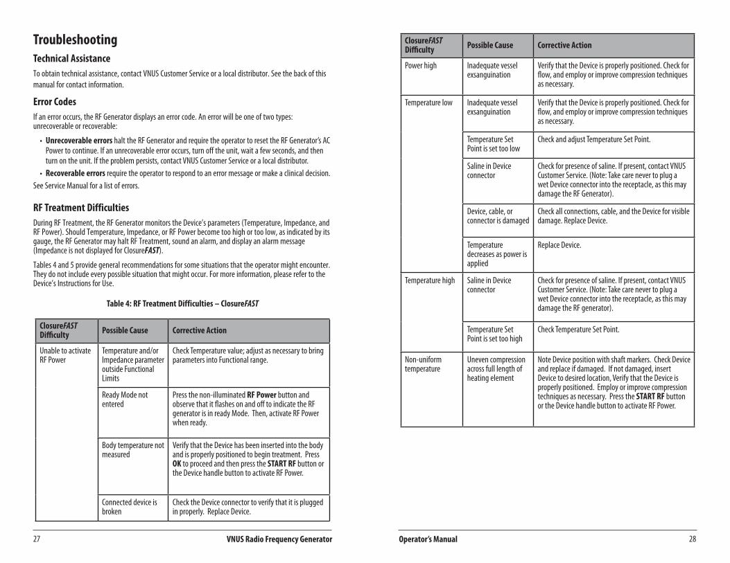
RF Treatment DifficultiesDuring RF Treatment, the RF Generator monitors the Device’s parameters (Temperature, Impedance, and RF Power) . Should Temperature, Impedance, or RF Power become too high or too low, as indicated by its gauge, the RF Generator may halt RF Treatment, sound an alarm, and display an alarm message (Impedance is not displayed for ClosureFAST) .
Tables 4 and 5 provide general recommendations for some situations that the operator might encounter . They do not include every possible situation that might occur . For more information, please refer to the Device’s Instructions for Use .
Table 4: RF Treatment Difficulties – ClosureFAST
ClosureFAST Difficulty Possible Cause Corrective Action
Unable to activate RF Power
Temperature and/or Impedance parameter outside Functional Limits
CheckTemperaturevalue;adjustasnecessarytobringparameters into Functional range .
Ready Mode not entered
Press the non-illuminated RF Power button and observe that it flashes on and off to indicate the RF generator is in ready Mode . Then, activate RF Power when ready .
Body temperature not measured
Verify that the Device has been inserted into the body and is properly positioned to begin treatment . Press OK to proceed and then press the START RF button or the Device handle button to activate RF Power .
Connected device is broken
Check the Device connector to verify that it is plugged in properly . Replace Device .
ClosureFAST Difficulty Possible Cause Corrective Action
Power high Inadequate vessel exsanguination
Verify that the Device is properly positioned . Check for flow, and employ or improve compression techniques as necessary .
Temperature low Inadequate vessel exsanguination
Verify that the Device is properly positioned . Check for flow, and employ or improve compression techniques as necessary .
Temperature Set Point is set too low
Check and adjust Temperature Set Point .
Saline in Device connector
Check for presence of saline . If present, contact VNUS Customer Service . (Note: Take care never to plug a wet Device connector into the receptacle, as this may damage the RF Generator) .
Device, cable, or connector is damaged
Check all connections, cable, and the Device for visible damage . Replace Device .
Temperature decreases as power is applied
Replace Device .
Temperature high Saline in Device connector
Check for presence of saline . If present, contact VNUS Customer Service . (Note: Take care never to plug a wet Device connector into the receptacle, as this may damage the RF generator) .
Temperature Set Point is set too high
Check Temperature Set Point .
Non-uniform temperature
Uneven compression across full length of heating element
Note Device position with shaft markers . Check Device and replace if damaged . If not damaged, insert Device to desired location, Verify that the Device is properly positioned . Employ or improve compression techniques as necessary . Press the START RF button or the Device handle button to activate RF Power .

30
Français
Operator’s Manual29
Français
VNUS Radio Frequency Generator
ClosureFAST Difficulty Possible Cause Corrective Action
Impedance low (not displayed)
Saline in Device connector and/or receptacle
Check for presence of saline . If present, contact VNUS Customer Service . (Note: Take care never to plug a wet Device connector into the receptacle, as this may damage the RF Generator .) If saline is not present in Device connector or receptacle, perform a Saline Test to verify functionality of Device . Replace Device or instrument cable if Saline Test Impedance values are out of range .
Short circuit Replace Device .
Impedance high (not displayed)
Open circuit Check Device connection (disconnect and then re-connect) .
Table 5: RF Treatment Difficulties - ClosureRFS
ClosureRFS Difficulty Possible Cause Corrective Action
Impedance low Inadequate electrode-vein wall contact
Improve or employ vein compression techniques .
Saline in Device connector and/or receptacle
Check for presence of saline . If present, contact VNUS Customer Service . (Note: Take care never to plug a wet Device connector into the receptacle, as this may damage the RF Generator .) If saline is not present in Device connector or receptacle, perform a Saline Test to verify functionality of Device . Replace Device or instrument cable if Saline Test Impedance values are out of range .
Short circuit Replace Device .
Impedance high Coagulum formation on electrodes
Check Device tip for coagulum and remove as required .
Device not in contact with target tissue
Verify that Device is properly positioned .
Open circuit Check Device connection (disconnect and then re-connect) .
Power high Too much blood flowPullback rate too fast
Checkandimproveexsanguination.Verify proper pullback rate .
ClosureRFS Difficulty Possible Cause Corrective Action
Temperature low Inadequate vessel exsanguination
Verify that the Device is properly positioned . Check for flow, and employ or improve compression techniques as necessary .
Pullback rate too fast Verify proper pullback rate .
Temperature Set Point is set too low
Check and adjust Temperature Set Point .
Saline in Device connector Check for presence of saline . If present, contact VNUS Customer Service . (Note: Take care never to plug a wet Device connector into the receptacle, as this may damage the RF generator) .
Device, cable, or connector is damaged
Check all connections, cable, and the Device for visible damage . Replace Device .
Temperature high Saline in Device connector Check for presence of saline . If present, contact VNUS Customer Service . (Note: Take care never to plug a wet Device connector into the receptacle, as this may damage the RF generator) .
Temperature Set Point is set too high
Check Temperature Set Point .
Unable to activate RF Power
Temperature and/or Impedance parameter outside Functional Limits
Check Temperature and Impedance parameter values;adjustasnecessarytobringparametersinto Functional range .
Electromagnetic Interference (EMI)The RF Generator might cause interference that can affect other equipment . Such interference might occur during RF Treatment Mode or during any mode that performs low power measurements, such as Measure, Body Test, or Saline Test Modes .
If interference affects other equipment in the treatment area, move the RF Generator to a different location and move the RF Generator cord and the Device away from the susceptible equipment and its cords and cables .
The RF Generator is susceptible to interference from EMI emitted by other equipment . This could result in inaccurate RF Power delivery and possible injury to the patient . Additionally, RF Treatment might halt or the unit might restart due to a non-repeating event, such as memory corruption related to electrical or radiation events, power surges, or power spikes .
Possible sources of EMI interference can include, but are not limited to, cellular phones, radio transmitters, motors, telephones, lamps and other medical equipment, such as electrosurgical products and defibrillators . Restrict the use of this equipment in the vicinity of the RF Generator .

32
Français
Operator’s Manual31
Français
VNUS Radio Frequency Generator
Glossary of TermsAdvisory Limits – Limits on parameters, such as Temperature, Impedance, RF Power, Time, or a combination of these, outside of which RF Treatment is not optimal and corrective action is suggested .
Alarm Tone–TheAlarmTonesoundsiftheunitdetectsthataparameterhasexceededtheFunctionalLimits for the connected Device .
Body Test – Performs Temperature and Impedance measurements using the Device positioned in the patient for RF Treatment .
Device – An approved VNUS RF delivery or RF powered accessory (e .g ., catheter, that can be attached to the RF Generator) .
Default – A value for a setting that is assigned automatically by the RF Generator . Default values remain in effect unless reconfigured in the RFG Setup or Device Setup menu .
EMI – Electromagnetic Interference .
Error Log – Description of, and RF delivery data surrounding, an error condition . This data is stored for later retrieval .
Functional Limits – Limits on parameters, such as Temperature, Impedance, RF Power, Time, or a combination of these, outside of which RF delivery halts immediately .
Impedance – Ratio of instantaneous voltage divided by instantaneous current . Both ClosureFAST and ClosureRFSusemagnitudeimpedance(themagnitudeofthecomplexImpedancevector).
Informational Tone – The Informational Tone sounds if the unit detects that a parameter is between the Advisory and Functional Limits for the connected Device .
LCD – Liquid-Crystal Display .
MMC – MultiMediaCard .
Parameter – The parameters that govern the RF Treatment algorithm—Temperature, Impedance, RF Power, and/or Time, depending on the Device .
PC – IBM®-compatible Personal Computer .
Persistent Settings – Operator-adjustable settings that retain their value when the RF Generator is turned off, such as screen brightness and tone volume settings .
POST – Power On Self Test .
Power – Real Power [heating power = IRMS * VRMS * cosθ] delivered to a Device .
Power Limit–MaximumRFPowerthattheDevicecandeliver.
Power Measurement – Current RF Power being delivered .
Power Set Point – The desired RF Power .
RAM – Random Access Memory .
Recoverable Error – An error condition that requires the operator to respond to an error message or make a clinical decision .
ROM – Read-Only Memory .
Real Impedance–MagnitudeoftherealportionofthecomplexImpedancevector.
RF – Radiofrequency energy .
RFC – Radiofrequency Computer .
RFG – RF Generator .
RFG2 – Model number of VNUS RF Generator .
RF Treatment – Therapeutic RF delivery .
Saline Test – Performs Temperature and Impedance measurements using saline solution .
Setting – Operator-configurable controls listed within the RFG Setup and Device Setup menus .
Temperature – Temperature, as measured at the Device point of RF delivery .
Temperature Measurement – The current Temperature .
Temperature Set Point – The desired or target Temperature .
Therapeutic RF–RFPowerlevelsdeliveredbyaDevicethatexceed10mWaveragepower.Thistermisdefined to distinguish between RF Power levels used for RF Treatment and lower RF Power levels used exclusivelyforparametermeasurement.
Unrecoverable Error – An error condition that halts the RF Generator and requires the operator to reset the RF Generator’s AC Power to continue .
VNUS –VNUS®MedicalTechnologies,Inc.

RM 55-661-01 REV .C
5799 Fontanoso WaySan Jose, CA 95138 USATel: +1-408-360-7200Toll Free: +1–888–797–VEIN (8346)Fax:+1-408-365-8470
Covidien Ireland Limited,IDA Business & Technology Park,Tullamore
0123
Customer ServiceTel: +1-800-962-9888
MEDICAL EQUIPMENT MODEL RFG2 WITHRESPECTTOELECTRICALSHOCK,FIREANDMECHANICALHAZARDSONLYINACCORDANCEWITHUL60601-1
CAN/CSA C22 .2 NO .601 .1 75AK
®