Radiant Technology
30
Transcript of Radiant Technology


Item Code Item Description
#1 RTCM01
“The Real Stuff”
Radiant Technology
Commercial Material
Used for Metal & Pole
Building Insulation
#3 RTSSF1 Radiant Technology Single
Sided Reflective Insulation
Designed to reflect low heat loads on one side
only. A/C Duct and Chiller Lines
#4 RTDSF1
Radiant Technology Double Sided
Reflective Insulation
Used where there is no air space; where only
thermal heat is a factor. Available with adhe-
sive on both sides.
#5 DSRIP1
Radiant Technology Double Sided
Reflective Insulation with Acoustical Foam
Used inside truck and tractor cab ceilings &
walls. Available with adhesive on both sides &
can be laminated to cab interiors with a Peel &
Stick system.
#6SSFSM02 ¼” or ½”
Radiant Technology Single Sided Fire Seal
Reflective Insulation
Used for reflecting high heat loads on one side.
This is a fire proof foam. It can have adhesive
on one side. Firewalls - any areas where heat is
greater than 200ºF. Only reflects on one side.
Available in ¼” or ½”
#7 DSFM01 ¼” or ½”
Radiant Technology Double Sided Fire Seal
Reflective Insulation
Designed for reflecting high heat on either side.
Used where no air space is available. Available
in ¼” or ½” foam and can have adhesive on
both sides.
#8 SSFW2A1 Radiant Technology Single Sided Fire Seal
Insulation with 2 Frequency Acoustics.
Used under floor mats of tractors where High
Heat & Noise are a Factor.
#9 DSW2A01 Radiant Technology Double Sided
Reflective Insulation with 2 Frequency
Acoustics.
Used under the floor mats of agricultural
tractors and truck tractors top application.
#10 DSE2A02 Radiant Technology Double Sided
Reflective Insulation with 2 Frequency
Acoustics.
Used under the floor mats of agricultural
tractors and truck tractors bottom application.
#11 RTHAF31
Radiant Technology High Acoustical Foam
Designed for use in and around Generator
Sets. Material features two barriers and one
dampener. Available in 1” Thickness. Rolls are
available in 54” x 25’
#12 RSSFSM01 Radiant Technology Reinforced Single
Sided Fire Seal Insulation
Used for reflecting heat on one side. This is a
Reinforced Fire Proof Material. Primarily used
on Engine Side Fire Wall for heat and Noise.
The thicker the material, the greater the noise
attenuation.
RT TAPE Radiant Technology Reinforced Tape Available in 2” by 3”
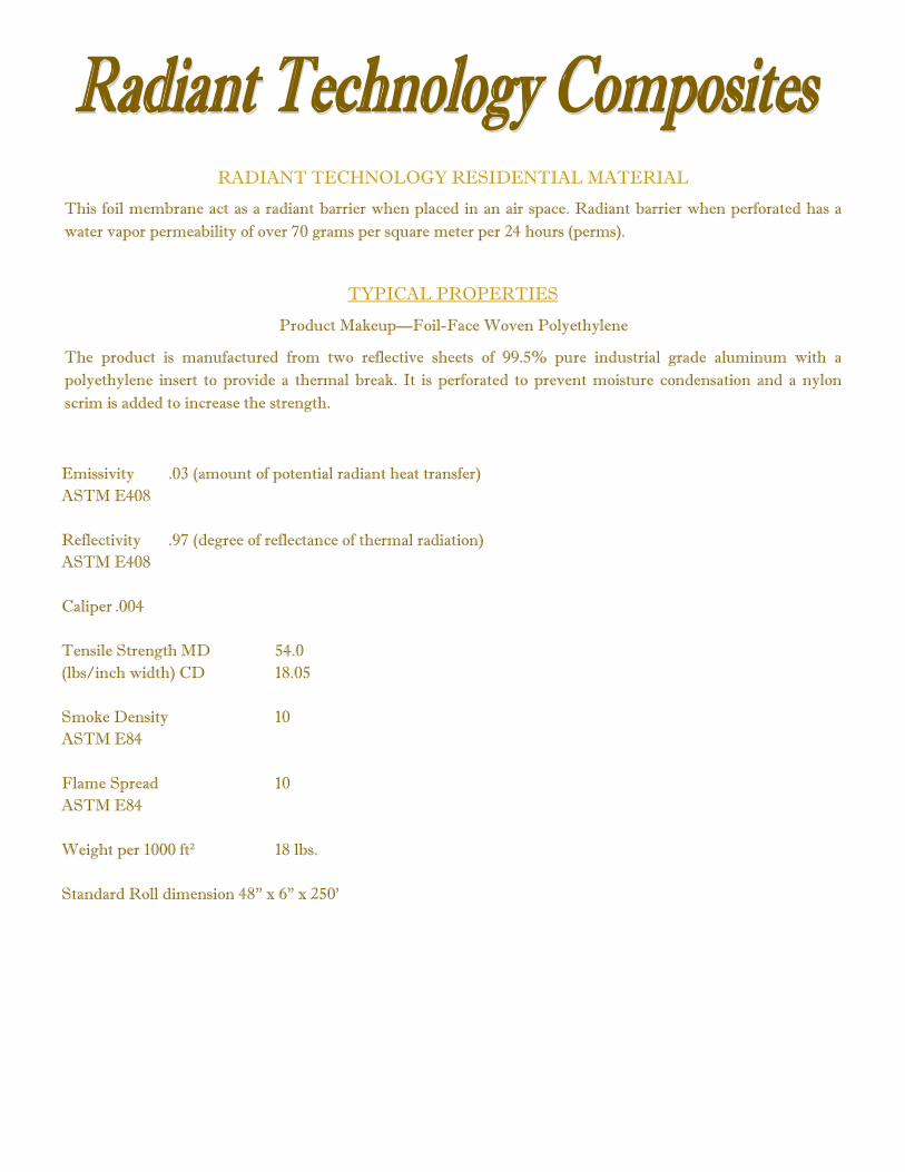
RADIANT TECHNOLOGY RESIDENTIAL MATERIAL
This foil membrane act as a radiant barrier when placed in an air space. Radiant barrier when perforated has a
water vapor permeability of over 70 grams per square meter per 24 hours (perms).
TYPICAL PROPERTIES
Product Makeup—Foil-Face Woven Polyethylene
The product is manufactured from two reflective sheets of 99.5% pure industrial grade aluminum with a
polyethylene insert to provide a thermal break. It is perforated to prevent moisture condensation and a nylon
scrim is added to increase the strength.
Emissivity .03 (amount of potential radiant heat transfer)
ASTM E408
Reflectivity .97 (degree of reflectance of thermal radiation)
ASTM E408
Caliper .004
Tensile Strength MD 54.0
(lbs/inch width) CD 18.05
Smoke Density 10
ASTM E84
Flame Spread 10
ASTM E84
Weight per 1000 ft² 18 lbs.
Standard Roll dimension 48” x 6” x 250’

PHYSICAL PROPERTIES
OF
ALUMINUM FOIL
Density 0.0976 lb/in
Specific Gravity 2.70 (approx.)
Melting Range 1190E-1215E
Electrical Conductivity 59ºIACS, Vol., 200%
IACS (approx.,), weight
Thermal Conductivity 53 CGS units at 25ºC
Thermal Coefficient of Linear Expansion 13.1 x 10^-6, per F from 68º to 212ºF
Reflectivity of white light, Tungsten filament lamp
85% to 88%
Reflectivity for radiant heat; from source at 100E F
95% (approx.)
Emissivity, at 100E 5% (approx.)
Atomic number 13
Atomic Weight 26.98
Valence 3
Strongly Electropositive 1.5/v
Specific Heat at 20EC 0.21-0.23 cal/gm/ºC
Boiling Point 3200ºF
Temperature Coefficient of Resistance for Alumi-
num
(Representative values per ºC)
Temperature ºC Coefficient
20 0.0040-0.0036
100 0.0031-0.0028
Low temperature properties — Aluminum increases in strength and ductility as temperature is
lowered, even down to –320ºF.

TABLE OF PROPERTIES
Radiant Technology Double-Sided Reflective
Insulation (RTDSF1)
4
PROPERTY NATURAL PROPERTY FACTOR TEST STANDARD POLYPROPELYNE
Specific Gravity 1= Water D792 .90-.91
Density lb/in^3 D792 .033
Tensile Strength PSI D638+ 4000-6000
Elongation % D638+ 100700
Compressive Strength 1%P SI D695 3500-8000
Flexural Strength PSI D790 5000-8000
Impact Strength, Izod ft/lb/in of notch D256A .4-1.0
Hardness Rockwell D785 R80-100
Thermal Conductivity BTUin/br/ft E/F C177 1.22-2.8
Thermal Expansion 10^5in/in F D696 5.8
Resistance to Heat F Continuous — 200
Melt Point F EF D1525 >275
Brittleness Temp. F EF D7646 -20 to 32
Deflection Temp 264psi EF D648 115-140
Deflection Temp 66psi EF D648 185-250
Volume Resistivity ohm/cm D257 6.5 x 10^16
Dielectric Strength V/10^3in D149 600-650 (1.25)
Dielectric Constant 50-100 Hz D150 2.1-2.3
Dielectric Constant 10^3 Hz D150 2.1-2.3
Dielectric Constant 10^6 Hz D150 2.1-2.3
Dissipation Factor 50-100Hz D150 .0003
Dissipation Factor 10^3 Hz D150 .0003
Water Absorption 24 hr % D570 .01-.03
Water Absorption Saturation % — .01-.03
Burn Rate Description D635 Burns
Effect of Sunlight Description D543 Affected
Wear Factor (k) K x 10^10 — —
Coefficient of Friction Dynamic — —

Product Data
Fire-Seal Institutional Foam
Physical Properties
TEST TEST METHOD TYPICAL VALUE
Density ASTM-D-3574 (A) 6 PCF +/-.5
Indentation Force
Deflection @ 25% ASTM-D-3574 (B1) 35 +/- 10 M
Compression Test ASTM-D-3574 (D) 20% Maximum
Tear Resistance ASTM-D-3574 (F) 2 PSI Minimum
Tensile Strength ASTM-D-3574 (E) 10 PSI Minimum
Elongation to Break ASTM-D-3574 (E) 110% Minimum
Fire-Seal Institutional Foam
Flammability
TEST TEST METHOD TYPICAL VALUE
Radiant Panel ASTM-D-3675 .5 or Less (No Melt/No Drip)
Oxygen Index ASTM-D-2863 65% Minimum
Underwriters Laboratory (UL)
Flame Resistance UL 94 HF– 1 Pass
Flame Retardance
Resilient Filling
Material Used in Upholstered
Furniture
Cal X 117
Section A
Section D
Pass
Pass
Flammability of High Risk &
Public Occupancy Mattresses
Cal X 133 Pass
Flammability of High Risk Seating Boston Fire Code Approved
Federal Aviation Administration
Flammability of Aircraft Seating
FAR 25.853
Part II Appendix F Pass
Federal Aviation
Administration
Compartment Interior
FAR 25.853
Volume III Para (A)
Para (B)
Pass
Pass
Department of
Transportation
Motor Vehicle
Safety Standard X 302
Pass

Product Data
Fire-Seal Institutional Foam Smoke Generation
TEST TEST METHOD TYPICAL VALUE
National Bareau of Standards (MBS
Smoke Chamber Test) Smoke
Generation Characteristics of Foam
ASTM-E-662
FLAMING MODE TYPICAL VALUE
Ds @ 1.5 Minutes 40 Maximum
Ds @ 4.0 Minutes 70 Maximum
D Maximum 100 Maximum
SMOLDERING MODE TYPICAL VALUE
Ds @ 1.5 Minutes 40 Maximum
Ds @ 4.0 Minutes 70 Maximum
D Maximum 100 Maximum
*All testing performed at 1” Thickness
TEST TEST METHOD TYPICAL VALUE
McDonnel-Douglas Acute Rela-tive (Count of Los Angeles Pur-chase Standard No. 951-3 (3-85)}
MASA CA-152056 Toxic Gas Af-fect on Living Organisms (Mice) Fuel Source: 1 gram test material Heat Source: 3.5 amps for 200 sec
a. Time to incapacitation not less than 15 min +/- 30 sec.
b. Time to death not less than 30 min +/- 30 sec.
a. Pass
b. Pass
Fire-Seal Institutional Foam
Toxicity
TEST TEST METHOD TYPICAL VALUE
McDonnel-Douglas Acute Rela-tive Toxicity Test
MASA CA-152056 (Enhanced) Toxic Gas Affect on Living Organisms (Mice)
Fuel Source: 2 gram test material Heat Source: 7 amps for 200 sec
Total Test Time: 30 Min.
a. Time to incapacitation not less than 15 min +/- 30 sec.
b. Time to death not less than 30 min +/- 30 sec.
a. Pass
b. Pass

NOISE BARRIER/ABSORBER COMPOSITE
RTHAF31 W/GLUE
11
Type Polyurethane/polyester
Density 2.0 lbs./ft^3
Color Charcoal gray
Thickness/decoupler 1/4”
Thickness/absorber 3/4”
Service Temperature -40EF low, 225EF high
K factor @ 30EF .26 BTU in/hr x ft x EF
FOAM VINYL BARRIER
Type Flexible polyvinylchloride
Thickness 3/32 inch
Weight/Thickness 1.0 lbs/ft
Color Charcoal gray
FACING
(absorber foam side) Aluminized polyester (mylar) 2.5
mils thick, reinforced with coated
fiberglass fabric
ADHESIVE
(decoupler foam side) Pressure-sensitive 4 mils thick un-
supported acrylic
FLAMMABILITY
MVSS 302
ACOUSTICAL PROPERTIES
Frequency in Hz 125 250 500 1K 2K 4K
Sound Transm. Loss in dB 21 27 30 25 43 62 STC 30(1)
Sound Abs. Coefficients .17 .55 .55 .19 .41 .37 NRC.45(2)
(1) Ref. Riverbank Acoustical Laboratories, Test TL82-183
(Composite adhered to 16 ga. sheet metal.)
(2) Ref. Riverbank Acoustical Laboratories, Test A91-100
AVAILABILITY
Rolls 54” wide x 25 ft
Sheets 54” wide x specified length
Die-cut Parts As specified


The following are the results of a 5th wheel unit with the Radiant Technology #4 material in it. Testing
done in unit roof. The insulation is placed under OSB board and on top of fiber glass.
Units Tested, each had one identical roof mounted A/C unit. 13,500 BTU
Test we are identifying is an A/C pull down. Heat room heated +110ºF. Thermostat set at 70ºF A/C
unit turned on and units began pull down.
Unit #1 without Radiant Technology insulation took three hours to pull down 70ºF and held for a total
of four hours.
Unit #2 with Radiant Technology insulation material took one hour to pull down to 70ºF— Thermostat
was lowered to 60ºF and unit at the end of a seven hour test had pulled down to 60.5ºF and held it.
This shows how the material reacts with a saturated heat load and demonstrates that the material will
insulate and produce a calculated R value which is as great as the A/C unit can provide.
The difference between 60.5ºF and 110ºF is 49.5ºF and you cannot get it any greater unless you have a
compressor design too take it further.
These test show that the integration of these space age materials improve the comfort level of each and
every unit that uses it. This is a very affordable option and does not interfere with current construction of
the units.

Test done with Eagle Series Dina Truck
Truck Number D-9400435
Series Number 223*4337C3
Motor Number 43146911
Make Cummins
Model N14-435
Maximum Potential 435 HP @ 1600 RPM
Maximum Torque 1550 Lb-Ft @ 1200 RPM
Transmission 14 Speed Spicer
Temperature in ºF with A/C off. Windows Closed. On an up-climb in a five hour test.
Exterior Interior Exterior Interior
Firewall Right 190.4 89.6 192.2 89.6
Firewall Center 199.4 95.0 188.6 95
Firewall Left 172.4 84.2 179.6 86
Floor Right Front 156.2 87.8 161.6 86
Floor Right Back 150.8 78.8 150.8 80.6
Floor Center Front 181.4 80.6 183.2 82.4
Floor Left Front 143.6 84.2 149.0 84.2
Exterior Interior Exterior Interior
Firewall Right 190.4 89.2 192.2 91.4
Firewall Center 188.6 95 188.6 96.8
Firewall Left 179.6 86 177.8 89.2
Floor Right Front 161.6 84.2 161.6 86
Floor Right Back 150.8 82.4 156.2 84.2
Floor Center Front 185.0 82.4 192.2 84.2
Floor Left Front 186.8 86 152.6 87.8
Exterior Interior Materials Used
Firewall Right 192.2 89.2 SSFSMO1 1/4 W/GLUE
Firewall Center 190.4 95 SSFSMO1 1/4 W/GLUE
Firewall Left 179.6 87.8 SSFSMO1 1/4 W/GLUE
Floor Right Front 165.2 84.2 DSFSSFS 1/4 W/GLUE
Floor Right Back 159.8 82.4 DSFSSFS 1/4 W/GLUE
Floor Center Front 192.2 82.4 RTDSF1 W/GLUE
Floor Left Front 149.0 87.8 RTDSF1 W/GLUE
SSFSM01 1/4 W/Glue= Single sided fireseal with glue
RTDSF1 W/Glue= Double sided foam with glue
DSFSSFS W/Glue= A combination of the SSFSMO1 1/4 W/Glue & RTDSF1

Results of Various Studies on The Effect of Radiant Barrier
Summer & Winter Tests
Test Facility Conditions Results
(% Reduction of Heat Transfer)
Oak Ridge Federal Lab
Summer Test
A. Radiant Barrier in Roof Truss with R-19 insulation
B. Radiant Barrier on Top of R-19 insulation
28%
39%
35%= 17% reduction in
Electrical Consumption
Tennessee Valley Authority
Summer Test
A. Radiant Barrier in Roof Truss with R-19 insulation
B. Radiant Barrier on Top of R-19 insulation
Winter Test
(Temperature as mild as 65º)
A. Radiant Barrier in Roof Truss with R-19 insulation
B. Radiant Barrier on Top of R-19 insulation
34%
44%
12%
23%
Florida Solar Energy Center
University of Mississippi
Summer Test
Above R-19 insulation
On Top of R-19 insulation
45%
45%
Northeastern Illinois University
Winter Test– 1984
On Top of R-19 insulation
30-50%
Northeastern Illinois University
Winter Test– 1982
29 % Over Entire Winter
Texas A&M University
Summer Test
A. One Sided Barrier on top of R-19 insulation
B. Two Sided Barrier on Top of R-19 insulation
46%
78.2%
CASE HISTORY OF A WINTER
Northeastern Illinois University, Department of Earth Sciences, Feb. 1982
29 % LESS FUEL USED WITH FOIL RADIANT BARRIER
SAVED $580 PER YEAR (1981 PRICES)
50% RETURN ON INVESTEMENT
PAYBACK—2 YEARS
Location:………………………………………… Winnetka, Il.
Building Type:………………………………….. Two story Victorian, residential
Square Footage:………………………………… 2300 Square Feet applied to roof rafters
Existing Insulation:…………………………….. 6” fiberglass batts, 2” vermiculite
Building Heat:………………………………….. Forced Air, Gas
Cost of Installation:…………………………….. $1,150
Other Comments:………………………………. Monitored closely by University Science
Professor using indoor and outdoor recording
thermometers with analysis of fuel use per
degree day.

Product Data
Fire-Seal Insulation Foam
TYPICAL SOUND ABSORPTION COEFFICIENT FOR
SAMPLE THICKNESS 24MM
200 400 800 1600 3200 6400
FREQUENCY, Hz
SO
UN
D A
BS
OR
PT
ION
CO
EF
FIC
IEN
T
1.0
0.9
0.8
0.7
0.6
0.5
0.4
0.3
0.2
0.1
0
100
2.4
2.2
2.0
1.8
1.6
1.4
1.2
1.0
0.8
0.6
0.4
0.2
0 10 20 30 40 50 60 70 80 90 100
THICKNESS, MM.
‘R’ V
AL
UE
, (m
² K
/W
)
TYPICAL ‘R’ VALUES (m² K/W) AT VARYING
THICKNESS


RESULTS OF A SIDE BY SIDE TEST
CONDUCTED IN DALLAS, TEXAS, JULY 1980
TEST HOMES EACH:
R-19 Ceiling Insulation
A-11 Wall Insulation
3528 square feet
Same Appliances
Same A/C Units
TEST HOME A:
No Radiant Barrier
5383 kwh used @ $325.00
TEST HOME B:
Radiant Barrier in Ceiling and
walls. Reflective tape also used
around doors and windows. 2054
kwh used @ $117.00
NO RADIANT BARRIER
WITH RADIANT BARRIER
ROOF SURFACE TEMP 164º
INSIDE ROOF SURFACE TEMP 159º
R-19
INSULATION
INSULATION STORES HEAT
SURFACE TEMP.
AT INSULATION
151º
INSIDE AIR
TEMP. 78º
AIR TEMP IN ATTIC 154º
CEILING SURFACE TEMPERATURE 100 DEGREES
ROOF SURFACE TEMP 164º
INSIDE ROOF SURFACE TEMP 159º
AIR TEMP IN ATTIC 154º
R-19
INSULATION
UNDER
RAD. BARRIER
RADIANT BARRIER
INSULATION SURFACE TEMP. 112º
INSIDE AIR TEMP. 78º
CEILING SURFACE TEMPERATURE 78 DEGREES
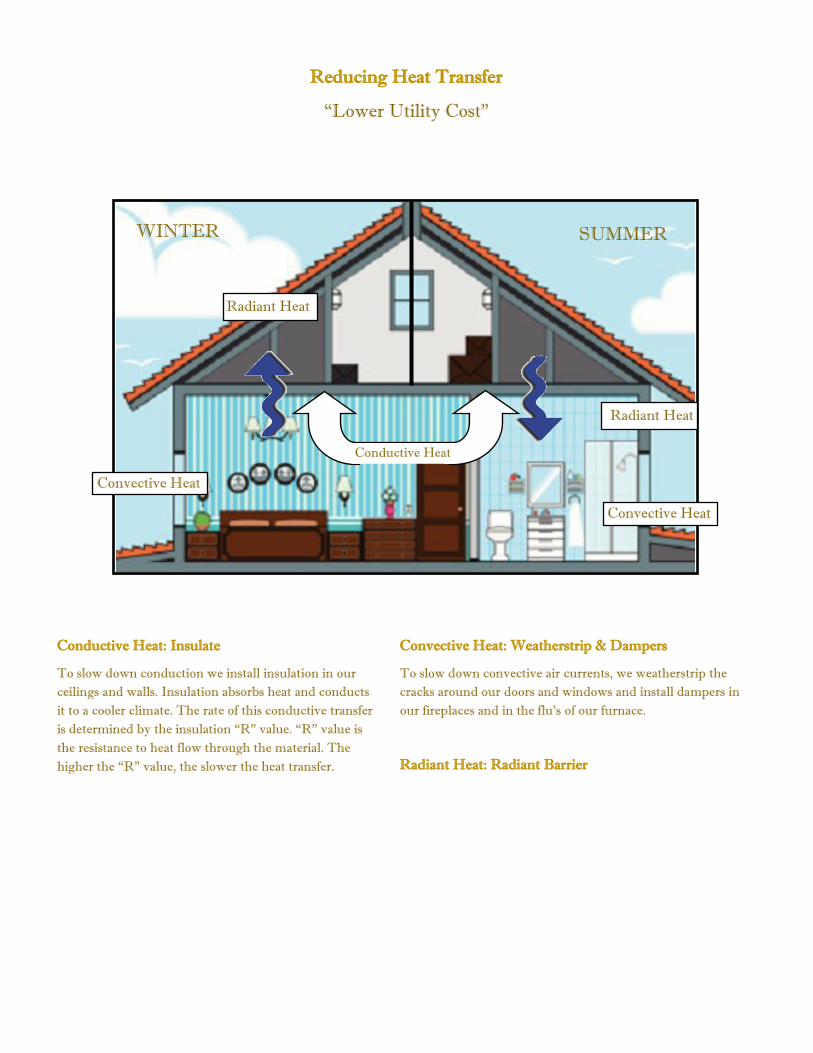
Reducing Heat Transfer
“Lower Utility Cost”
WINTER SUMMER
Radiant Heat
Conductive Heat
Radiant Heat
Convective Heat
Convective Heat
Conductive Heat: Insulate
To slow down conduction we install insulation in our
ceilings and walls. Insulation absorbs heat and conducts
it to a cooler climate. The rate of this conductive transfer
is determined by the insulation “R” value. “R” value is
the resistance to heat flow through the material. The
higher the “R” value, the slower the heat transfer.
Convective Heat: Weatherstrip & Dampers
To slow down convective air currents, we weatherstrip the
cracks around our doors and windows and install dampers in
our fireplaces and in the flu’s of our furnace.
Radiant Heat: Radiant Barrier

How Radiant Barrier Works
SUN
Radiation
93% Absorption
93% Absorption
Radiation
Conduction
93% Absorption
93% Emissivity
SUN
93% Absorption
Radiation
97% Reflectivity
93% Absorption Radiation
Conduction
3% Emissivity
3% Absorption
99.5% Pure Aluminum
R-30 R-19 R-11 R-30 R-19 R-11
Radiation is the Primary Mode of Heat Transfer
Down Heat Flow
0%
10%
20%
30%
40%
50%
60%
70%
80%
90%
100%
0%
Up to
93%
SUMMER HEAT GAIN
THROUGH CEILING/ROOF
Up Heat Flow 100%
90%
80%
70%
60%
50%
40%
30%
20%
10%
0%
50%
to
75%
Up to
45%
WINTER HEAT LOSS
THROUGH CEILING/ROOF
Radiation Conduction Convection
Radiation Conduction Convection
5% to 7%
5% to 7%

SUMMER TEST
Insulation
WITHOUT
RADIANT BARRIER
Radiant Barrier
Insulation
WITH
RADIANT BARRIER

WINTER TEST
Heat Source
Insulation
WITHOUT
RADIANT BARRIER
Heat Source
Insulation
Radiant Barrier WITH
RADIANT BARRIER

Revolutionary insulation packages
from Radiant Technology have an insulating
value greater than 20 inches of mass insula-
tion. Our unique products will keep you
warmer in the winter and cooler in the sum-
mer.
How can this be possible?
After researching the superior insula-
tion technology used in the space program,
Radiant Technology has taken this knowl-
edge and reproduced it into an easy to use,
affordable product called Radiant Technology
Reflective Insulation. Unlike mass insulation,
Radiant Technology Reflective Insulation
doesn't absorb heat which causes heat trans-
fer, but instead reflects heat from both sides.
This means that in the winter any heat gener-
ated within the interior of the fifth-wheel is
contained for the warmest interior possible. In
the summer, heat is deflected from entering
the interior of the fifth-wheel allowing the air
conditioner to cool more efficiently. Radiant
Technology Reflective Insulation has been
tested in the extremes of the desert in tem-
peratures of 140ºF and in cold areas of –50ºF.
Reflective Thermal Insulation used in roof area.
Reflective Thermal Insulation used in floor.
FIFTH-WHEEL TRAVEL TRAILERS
CONVENTIONAL TRAVEL TRAILERS
CLASS A MOTOR HOME
CLASS C MOTOR HOME
Benefits of Reflective Insulation
1. Provides a constant vapor barrier.
2. Thermally will improve the efficiency of
A/C Heater unit no matter what climate.
3. Will extend the life of A/C Heater unit.
4. Will provide the efficiency of LP furnace.
FAA may tell airlines to replace insulation
The following is a short article of why the FAA is considering replacing any insulation containing
metallized Mylar for fire resistant insulation such as the insulation manufactured by Radiant Technology
By Alan Levin
Wed., Aug 11, 1999
USA TODAY
FINAL EDITION
Section: NEWS
Page 4A
U.S. airlines would have to replace dangerously flammable insulation on more than 700 jets according to a proposal soon to be
announced by federal officials, USA TODAY has learned. The proposed order would be costly, and airlines contend it could
require some of them to take jets temporarily out of service. The order is far less dramatic than the Federal Aviation Admini-
stration predicted last fall when it first announce it was stepping up efforts to review the safety of insulation material.
The proposed FAA order would require airlines with MD-80,MD-90, MD-11 and DC-10 jets to replace the insulation that
rests just inside the aircraft skin because it was found to catch fire too easily, according to people who have been briefed on the
FAA’s plans.
The insulation, similar to household insulation, protects against extreme temperature changes and reduces interior noise.
The Swissair MD-11 that crashed Sept. 2 off Nova Scotia contained the same insulation material, known as metallized Mylar,
named in the proposed FAA order. The cause of that crash has not been identified, but the flight crew reported smoke and
investigators found evidence of fire in the jet’s ceiling area. All 229 people aboard were killed.
The FAA also is preparing a more comprehensive series of regulations to be announces later this year that would require that
the insulation blankets be composed of materials that also resist jet-fuel fires outside the fuselage, USA TODAY has learned.
Such a rule would give people more time to escape after a crash, but the FAA has not said how broadly the rule would be ap-
plied.
Airlines say they support the replacement of insulation containing metallized Mylar. But in recent days they have asked the
FAA to postpone its order so that a test replacement can be conducted.
“Foremost among our concerns is the potential for disturbing wiring during the insulation replacement process in such a way
that would increase the likelihood of wiring failures,” said a letter dated Aug. 4 from the Air Transport Association, the air-
lines’ trade group, to the FAA.
The airlines have estimated that the replacement would cost as much as $1 million per aircraft, or more than $700 million for
the entire fleet of jets affected. Some officials say the cost would be far less because the FAA requires a partial removal of insu-
lation blankets during heavy maintenance performed every few years.
The proposed rule gives airlines four years to comply. An estimated 729 jets would fall under the order. It would be subject to
public comment before taking effect.
The FAA’s proposed action falls far short of the 5,000 aircraft that officials predicted last year could be affected by an insulation
replacement order. FAA technicians found that other materials were not as flammable as they had feared.

INSULATION FOR VAN CONVERTIONS


RADIANT SHIELD INSULATION TRAINING INFORMATION
Radiant Shield insulation isn't new, to motor coaches, travel trailers, 5th wheel trailers or commercial applications. This is
the technology used to insulate Space Shuttles, space suits used outside the shuttle and other spacecraft. Radiant Technol-
ogy reflective insulation is our designated name for this type of insulation.
The unique feature that separates this insulation from the conventional fiberglass, wool and foam insulation is the heat
transfer mechanism. Most conventional insulation slows the conduction of heat through the material. Radiant Shields and
our reflective insulation reflect the heat back where it came from.
Heat flows from the higher temperature to the lower temperature by three mechanisms: Conduction, Convection and
Radiation.
1. Conduction is the movement through materials and from one material to another when they are in intimate contact.
2. Convection is heat flow through a moving gas or liquid.
3. Radiation is where the heat transfer is in the electromagnetic spectrum (infrared), like feeling the sun on your face.
With these basics in mind lets look at the resistance to heat flow in a simple insulation system. The simplest system is a
wall using conduction resistance only. The high temperature flows towards the low temperature and the flow is resisted
by the insulation.
Conductive insulation is listed with an R-value; which as you can expect id the resistance to heat flow. The higher the R
value the better the insulation resistance and the more the heat flow is slowed. The R-value is based on the material and
the thickness. The same material applied twice the thickness has twice the R-value. For each inch of thickness of fiber-
glass in the wall the R-value is 3.7. If you put 1 ½ inch thickness of fiberglass in the ceiling of a typical coach you get an R-
value of 5.6 (3.7X1.5=5.6). This is basically what comes in a typical coach. As a comparison, urethane foam has an R-value
of about 7.2/inch (there is a wide range of R values for foam). If this were placed in the ceiling of a coach with 1½inch
space the R– value of the insulation would be 10.8 (7.2X1.5=10.8). Pretty much double the R-value of the insulation of
fiberglass; a pretty good improvement, we’ve cut in half the flow of the heat through the insulation for any given tempera-
ture difference. The foams are pretty much the best conductive insulation available and this is why they are so popular.
But wait, there is more. Remember that radiation heat transfer can also be affected by insulation. When a panel such as
the skin of the coach gets hot, and there is no insulation in the way, the panel emits the heat into the cold space. If you
have been in a coach with no insulation, so you can see the inside of the roof skin, on a sunny day you will remember the
amount of heat being given off (radiated) by the inside surface of the roof. A lot of this radiation can transfer through
transparent and semi transparent materials and some gets lost in these materials. If you reflect this radiant heat back to the
skin you can cut down on the heat coming into the insulation. A technique called Radiant Shielding is used to reflect the
radiant heat and prevent it from entering into the insulation where it would be conducted into the cool space (interior of
the coach). In its basic application our reflective foil is placed a small distance below the roof decking The space below the
foil is filled with fiberglass insulation. The space above and below the reflective insulation allows for the heat to reflect off
the insulation and allows for heat to be directed away from the roof (in summer) or hold the heat (in winter) in the living
area of the coach. Thus, the reflective insulation increases the existing value of the fiberglass insulation by holding in heat
(in the winter) or reflecting heat from the interior (in the summer).
Because of the explanation above the characteristics of heat transfer (R-Values reflective insulation cannot be give an R-
Value itself. It must be a calculated value based upon heat conditions at the time along with the existing value based upon
heat conditions at the time along with the existing values of the type of insulation installed in the coach (i.e.: fiberglass,

Foam, wool, etc.) to include values in materials such as ceiling panels, rubber or fiberglass exterior roof used. Calculating the
R-value for our reflective insulation with these items in mind we can expect a value of R-38 with an exterior heat of 80 degree
Fahrenheit using normal fiberglass insulation with an R-Value of R-12 in the roof. Remember this value will increase as the
temperature increases. Radiant Technology reflective insulation reflects heat at a rate of 97%. The reflective insulation also
acts a perfect vapor barrier. This will insure no moisture build up and holds in the existing insulation of the roof. This will
eliminate any mold or mildew being created.
Benefits of the use of Radiant Technology reflective insulation include the extended life of the air conditioner, increased effi-
ciency of the L.P furnace (far less use of L.P0 and an even comfort through the coach. The temperature should not vary more
than 2 degrees from the floor to ceiling and wall to wall through the coach in any weather condition. A typical “Artic Pack)
reflective insulation package used would include the following installation in the areas of: complete roof — front and rear wall
areas of coach — complete under floor area (above exterior frame covering such as “Darko”, galvanized metal or other cover-
ing) — slide out floors (under carpet) and under bed area in 5th wheel models. Some companies will also use the reflective
insulation on the sidewalls of their coaches. Reflective insulation is not used in any lamination process for sidewalls, roof or
floors for the reflective characteristics of the heat transfer will “melt” or loosen the glue used in the lamination process. That is
why it must stay on the outside position facing away from the interior of the coach to reflect heat away from the interior (in the
summer) and hold the heat in during the winter conditions.


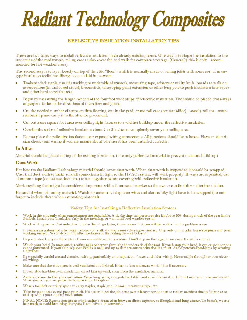
REFLECTIVE INSULATION INSTALLATION TIPS
These are two basic ways to install reflective insulation in an already existing home. One way is to staple the insulation to the underside of the roof trusses, taking care to also cover the end walls for complete coverage. (Generally this is only recom-mended for hot weather areas).
The second way is to lay it loosely on top of the attic “floor”, which is normally made of ceiling joists with some sort of mass-type insulation (cellulose, fiberglass, etc.) laid in between.
Tools needed: staple gun (if attaching to underside of trusses), measuring tape, scissors or utility knife, boards to walk on across rafters (in unfloored attics), broomstick, telescoping paint extension or other long pole to push insulation into eaves and other hard to reach areas.
Begin by measuring the length needed of the four foot wide strips of reflective insulation. The should be placed cross-ways or perpendicular to the directions of the rafters and joists.
Cut the needed number of strips on firm flooring, out in the yard, or use roll ease (contact office). Loosely roll the mate-rial back up and carry it to the attic for placement.
Cut out a one square foot area over ceiling light fixtures to avoid het buildup under the reflective insulation.
Overlap the strips of reflective insulation about 2 or 3 inches to completely cover your ceiling area.
Do not place the reflective insulation over exposed wiring connections. All junctions should be in boxes. Have an electri-cian check your wiring if you are unsure about whether it has been installed correctly.
In Attics
Material should be placed on top of the existing insulation. (Use only perforated material to prevent moisture build-up)
Duct Work
For best results Radiant Technology material should cover duct work. When duct work is suspended it should be wrapped. Check all duct work to make sure all connections fit tight so the HVAC system, will work properly. If vents are separated, use aluminum tape (do not use duct tape) to seal together before covering with reflective insulation.
Mark anything that might be considered important with a fluorescent marker so the owner can find them after installation.
Be careful when trimming material. Watch for antennas, telephone wires and alarms. Sky light have to be wrapped (do not forget to include these when estimating material)
Safety Tips for Installing a Reflective Insulation System
Work in the attic only when temperatures are reasonable. Attic daytime temperatures rise far above 100º during much of the year in the Sunbelt. Install your insulation early in the morning, or wait until cool weather sets in.
Work with a partner. Not only does it make the job go faster, it also means that you will have aid should a problem occur.
If yours is an unfinished attic, watch where you walk and use a movable support surface. Step only on the attic trusses or joists and your working surface. Never step on the attic insulation or the ceiling drywall below it.
Step and stand only on the center of your moveable working surface. Don’t step on the edge; it can cause the surface to tip.
Watch your head. In most attics, roofing nails penetrate through the underside of the roof. If you bump your head, it can cause a serious cut or punctured. If your skin is punctured by a nail, and up to date tetanus vaccination is a must. Avoid potential problems by wearing a hard hat.
Be especially careful around electrical wiring, particularly around junction boxes and older wiring. Never staple through or over electri-cal wiring.
Make sure that the attic space is well ventilated and lighted. Bring in fans and extra work lights if necessary.
If your attic has blown– in insulation, direct fans upward, away from the insulation material.
Avoid exposure to fiberglass insulation. Wear long pants, along-sleeved shirt, and a particle mask or kerchief over your nose and mouth. Wear gloves if you are particularly sensitive to fiberglass.
Wear a tool belt or utility apron to carry staples, staple gun, scissors, measuring tape, etc.
Take frequent breaks and pace yourself. It’s better to get the job done over a longer period than to risk an accident due to fatigue or to end up with a poor-quality installation.
FINAL NOTE: Recent tests are now indicating a connection between direct exposure to fiberglass and lung cancer. To be safe, wear a face mask to avoid breathing fiberglass if you have it in your attic.

Walk Through Inspection and Sign Off Sheet
1. Visual of Ceilings—Cracks, Water Leaks and Roof Leaks — Comment:
__________________________________________________________________________________
2. Visual of Walls—Water Leaks, Stains or Cracks — Comment:
__________________________________________________________________________________
3. Visual of Windows (Point out any cracked, chipped or broken glass) :
__________________________________________________________________________________
4. Visual of Duct Work in Attic, Crawl Space (Checking for broken, collapsed, damaged, disconnected
trunk lines) Make Sure all are connected:
__________________________________________________________________________________
5. Visual of Air Circulation in Attic—Check for closed, obstructed or not proper ventilation– May need
to recommend turbulator air management system.
__________________________________________________________________________________
__________________________________________________________________________________
Customer Recognizes items on Comment List
_________________________________Customer
_________________________________Dealer/Installer
Customer Acknowledges Installation was done correctly
_________________________________Customer
_________________________________Dealer/Installer
_________________________________Date of Completion