Radialventilatoren mit freilaufendem Rad ; ohne Gehäuse ... · Rosenberg productsare...
85
Rosenberg Ventilatoren GmbH Maybachstraße 1/9 D-74653 Künzelsau-Gaisbach Fon +49(0)7940 / 142-0 Fax +49(0)7940 / 142-125 www.rosenberg-gmbh.com [email protected] Radialventilatoren mit freilaufendem Rad ; ohne Gehäuse radial fans with free-running impeller ; without housing mit Aussenläufermotor/ mit Aussenläufer-EC-Motor/ mit IEC-Normmotor/ with external rotor motor with external rotor EC-motor with IEC-standard motor ECOFIT ETRI THE AIR MOVEMENT GROUP
Transcript of Radialventilatoren mit freilaufendem Rad ; ohne Gehäuse ... · Rosenberg productsare...

Rosenberg Ventilatoren GmbH
Maybachstraße 1/9
D-74653 Künzelsau-Gaisbach
Fon +49(0)7940 / 142-0
Fax +49(0)7940 / 142-125
www.rosenberg-gmbh.com
R a d i a l v e n t i l a t o r e n m i t f r e i l a u f e n d e m R a d ; o h n e G e h ä u s e
r a d i a l f a n s w i t h f r e e - r u n n i n g i m p e l l e r ; w i t h o u t h o u s i n g
m i t A u s s e n l ä u f e r m o t o r /
m i t A u s s e n l ä u f e r - E C - M o t o r /
m i t I E C - N o r m m o t o r /
w i t h e x t e r n a l r o t o r m o t o r
w i t h e x t e r n a l r o t o r E C - m o t o r
w i t h I E C - s t a n d a r d m o t o r
ECOFIT
ETRI
T H E A I R M O V E M E N T G R O U P

Inhaltsverzeichnis Contents
Sicherheit und GarantieTypenschlüsselTechnische Beschreibung- Eigenschaften und Ausführung- Laufräder- Drehrichtung- Einströmdüsen- Motoren- Volumenstromüberwachung- Berührungsschutz- Explosionsschutz- Vorteile- Luftleistungskennlinien- Geräusche- Einbauempfehlung- Volumenstrom-Meßeinrichtung
Freilaufende Rädermit asynchron Außenläufermotor
- Erläuterung zu technischen Daten- Technische Beschreibung- Kennlinien 50 Hz
_KH_250-.. W - _KH_710_-.. W- Schnellauswahl 60 Hz- Abmessungen- Schaltbilder- Beispiele- Ausschreibungstext
Freilaufende Rädermit EC-Außenläufermotor
- Erläuterung zu technischen Daten- Technische Beschreibung- Kennlinien
GKH_280-.. W - GKH_560_-.. W- Abmessungen- Elektronische Kommutierungseinheit- Ausschreibungstext
Radialventilatoren mit freilaufendem Rad;ohne Gehäuse, mit Asynchron - Normmotor
- Erläuterung zu technischen Daten- Technische Beschreibung- Kennlinien
DKN_250-.. W - DKN_800_-.. W- Abmessungen- Schaltbilder- Ausschreibungstext
Safety and warrantyReference codeTechnical description- Features and Construction- Impeller- Direction of Rotation- Inlet Cones- Motors- Volume flow monitor / control- Protection against accidental contact- Explosion protection- Advantages- Air performance curves- Noise levels- Installation- Air volume testing device
Free running fanswith asynchronous external rotor motor
- Technical Description- Explanation of technical details- Performance curves 50 Hz
_KH_250-.. W - _KH_710_-.. W- Quick Selection 60 Hz- Dimensions- Wiring diagrams- Examples- Call for Tenders
Free running fanswith ec-external rotor- motor
- Technical Description- Explanation of technical details- Performance curves
GKH_280-.. W - GKH_560_-.. W- Dimensions- Electronic Commutating Unit- Call for Tenders
Radial fans with free-running impeller;with asynchronous standard motor
- Technical Description- Explanation of technical details- Performance curves
DKN_250-.. W - DKN_800_-.. W- Dimensions- Wiring diagrams- Call for Tenders
Seite /Page
456
7
89
101213
A
A1A2A4
A24A26A28A29
B
B1B2B5
B12B14B16
C
C1C2C4
C15C18C21
3
Bitte beachten Sie beim Einbau und beim Betrieb derRosenberg-Ventilatoren folgende Hinweise:
Montage- und Elektroarbeiten nur durch ausgebildetesund eingewiesenes Fachpersonal und nach den jeweilszutreffenden örtlichen Vorschriften oder Normen.
Die aktuell gültige Betriebsanleitung ist einzuhalten!
Änderungen in Konstruktion und Design behalten wir unsim Sinne des technischen Fortschritts vor.
Qualitätsmanagementsystem DIN EN ISO 9001Rosenberg-Produkte werden nach modernsten Pro-duktionsverfahren hergestellt. Die konsequente Über-wachung der Fertigung durch unser Qualitätsmanage-mentsystem ermöglicht einen gleichbleibend hohenQualitätsstandard. Durch unser außerordentlich hohesKnow-how in den verschiedensten Bereichen der Lüft-ungs- und Klimatechnik sowie der Motorenfertigungunterliegen unsere Produkte einer stetigen Weiter-entwicklung auf den modernsten Stand der Technik.Dabei können wir auf die jeweiligen Bedürfnisse schnellund flexibel reagieren. Der Kundenwunsch steht dabei füruns stets im Mittelpunkt.
GewährleistungsbestimmungenFür Auswahl, Auslegung und Einsatz der Ventilatoren istder Käufer verantwortlich. Für Sach- und Rechtsmängelder Lieferung leistet der Lieferer unter Ausschluss weitererAnsprüche - vorbehaltlich Abschnitt VII. der gültigen Allge-meinen Geschäfts- bedingungen (AGB) - Gewähr.
Keine Gewähr wird insbesondere in folgenden Fällenübernommen:Ungeeignete oder unsachgemäße Verwendung, fehler-hafte Montage bzw. Inbetriebsetzung durch den Bestelleroder Dritte, natürliche Abnutzung, fehlerhafte oder nach-lässige Behandlung, nicht ordnungsgemäße Wartung,ungeeignete Betriebsmittel, mangelhafte Bauarbeiten,ungeeigneter Baugrund, chemische, elektrochemischeoder elektrische Einflüsse - sofern sie nicht vom Liefererzu verantworten sind.
Weist die vom Hersteller gelieferte Ware Mängel auf, sohat der Käufer Anspruch auf Ersatz des Produktes bzw.der Teile davon bis max. zur Höhe des Kaufpreises. Desweiteren hat der Lieferer das Recht der Nachbesserung ineinem angemessenen Zeitrahmen. Im Schadensfall istder Lieferer sofort und unverzüglich zu verständigen.Ersatzpflicht für weitere Mängel ist ausgeschlossen.
Für alle weiteren Vereinbarung wie z.B. Fristenregelung,Recht auf Wandlung usw. liegen unsere allgemein-gültigen AGB´s zugrunde. Die AGB erhalten Sie unterunserer Homepage: www.rosenberg-gmbh.com oderdirekt von einer unserer Niederlassung.
Please observe the following information prior toinstallation and operation of Rosenberg fans:
Installation and electrical installation work should only beperformed by skilled workers in accordance with appli-cable local laws and directives.
Only the current installation and operating instructions arevalid and are to be followed. We reserve the right tochange the construction and design without prior noticein line with technical development.
Quality Management System DIN EN ISO 9001Rosenberg products are manufactured according to stateof the art production techniques. A continuous high quali-ty standard is ensured by our Quality ManagementSystem. Our products are in a process of continuousdevelopment as a result of our extensive know how in thevarious areas of ventilation, climate control, and motorproduction and are produced in accordance with the latestmanufacturing technologies. Furthermore, we are able toreact quickly and flexibly to the individual needs of thecustomer. Our actions are centred around the customer’srequirements.
Warranty GuidelinesThe customer is responsible for selection, layout andoperation of the fans. The supplier gives warranty for faultyproducts, excluding further claims, in accordance withparagraph VII of the valid terms and conditions ofbusiness.
Warranty will not be given for the following instances:
Unfit or inappropriate usage, incorrect montage or faultyinstallation by the purchaser or a third party, normal wearand tear, incorrect or negligent handling, impropermaintenance, unsuitable operating material, faulty in-stallation, unsuitable fundament, chemical, electro-chemical or electrical influence - as long as they are notthe responsibility of the supplier.
If the goods delivered from the manufacturer are faultythen the customer has the right to receive a replacementor replacement of the faulty parts up to the maximum valueof the purchase price. The manufacturer also has the rightof repair the product within a reasonable time period.Themanufacturer must be informed immediately in the caseof damage.
The obligation to replace additional faults is herewithexcluded. Our general terms of business are the basis forall further agreements for example: time periods to repairor replace The general terms of business are available onour homepage www.rosenberg-gmbh.com or directfrom one of our subsidiaries.
Sicherheit und Gewährleistung Safety and warranty
4

Typenschlüssel / Reference code
Stromart / Type of currentD = Drehstrom / Three phaseE = Einphasenwechselstrom / Single phase A.C.G = EC- Motor- Antrieb / EC- Motor Drive
Ausführung / DesignKH= Freilaufendes Rad mit Außenläufermotor
Free running impeller with external rotor motorKN= freilaufendes Rad mit IEC Normmotor
Free running impeller with IEC motor
Bauform / TypeR = Motorlaufrad / Motorized impellerM = Ventilatoreinbaumodul / Fan module
B = Ventilatoreinbaumodul mit Montagebock /Fan module with mounting stand
Radnenngrösse / Impeller diameter355 = 355 mm
Polzahl / Number of poles2 = 2; 4 = 4; 6 = 6; 8 = 8; F = 2-2; G = 4-4; H = 6-6;M = 8-8; B = 10; C=12; N = 10-10; P = 12-12;O = 4-6; X = 4-8
Kabelausführung / Cable outletS = Kabel seitlich / Flying leadK = Klemmkasten / Terminal box
Radbaureihe / Type of wheelW = Wirkungsgradoptimiertes Laufrad
High efficiency impeller
Radbreite / Impeller widthin mm
Motortyp / Motor type Motorbauform / Motor design3 = 068 A = B34 = 080 (EC-080) B = B55 = 106 (EC-108)6 = 137 (EC-150)7 = 165
Paketlänge / Package length Motorbaugröße / Motor sizeA = 0 H = 7 06 = 063 16 = 160B = 1 I = 8 07 = 071 18 = 180C = 2 K = 9 08 = 080 20 = 200D = 3 L = 10 09 = 090 22 = 225E = 4 M = 11 10 = 100 25 = 250F = 5 N = 12 11 = 112G = 6 13 = 132
Fortlaufende Nummer / Consecutive no.
D K H R 355 -4 S W.110 .4 EC - 001K N A 06
5

Eigenschaften und Ausführungen
Die Rosenberg Radialventilatoren mit freilaufendemRad sind hauptsächlich für den Geräteeinbau konzipiertund kommen vorzugsweise in Klimageräten, Hygiene-geräten, Reinraumfiltereinheiten sowie RLT-Anlagen zumEinsatz. Bei der Entwicklung des rückwärts gekrümmtenLaufrades für den Einsatz ohne Spiralgehäuse wurdebesonderer Wert auf eine Wirkungsgradoptimierung übereinen weiten Kennlinienbereich bei hoher Leistungsdichteund gleichzeitig möglichst optimalem Geräuschpegel ge-legt. Die Ventilatoren sind zur Förderung von Luft undsonstigen, nicht aggressiven Gasen oder Dämpfen be-stimmt. Als Antriebsmotoren werden Asynchron-Aussen-läufermotoren, Elektronisch kommutierte (EC-) Aussen-läufermotoren sowie Standard Drehstrom IEC-Motorenverwendet.
Abhängig von der Motorausführung und der mechan-ischen Bauform sind die Ventilatoreinheiten lieferbar als:
• _KHR: Motorlaufrad ohne oder mit lose beigefügterEinströmdüse. (Aussenläufermotor)
• _KHM: Ventilatoreinbaumodul (Aussenläufermotor)• DKNB: Ventilatoreinbaumodul mit Montagebock
(IEC- Motor; Ausf. IM B3)• DKNM: Ventilatoreinbaumodul (IEC-Motor; IM B5)
Features and Construction
The Rosenberg Centrifugal Fans with free-runningimpeller of the range DKN_ .. W were designed for in-stallation in appliances such as air-handling-units, hyg-ienic- and clean room filter units as well as for RLT units.During the development of this unit with backward-curvedimpeller without scroll casing, special attention was paidto optimize the efficiency over a wide characteristic curvehaving at the same time high performance and an opti-mum sound power level. The fans are suitable to handleair and other non aggresive gases or fumes. The motorsare available as electronically commutated (EC) externalrotor motors or standard three phase IEC-motors.
Depending on the type of motor and the fan construction,the following fans are available:
• _KHR: Motorized impeller with or without inlet cone.(External rotor motor)
• _KHM: Fan module (External rotor motor)• DKNB: Fan module with mounting stand
(IEC-Motor; Type. IM B3)• DKNM: Fan module (IEC-Motor; IM B5)
_KHR _KHM
DKNB DKNM
6

LaufräderDie Laufräder mit 8 rückwärtsge-krümmten Schaufeln werden aus Alu-miniumblech (AlMg3) gefertigt undsind zusammen mit der Laufradnabeoder dem jeweils verwendeten Aus-senläufermotor entsprechend der Gü-testufe G2,5/6,3 nach DIN ISO 1940statisch und dynamisch gewuchtet.Auf Wunsch können die Laufräderauch aus Stahlblech mit Kunststoffbe-schichtung gefertigt werden.
DrehrichtungDie Drehrichtung der Laufräder ist serienmäßig rechts-drehend (gesehen auf die Ansaugseite). Bei falscherDrehrichtung (vorwärtsgekrümmt laufend) besteht Über-lastungsgefahr für den Motor. Daher sollte immer vorInbetriebnahme die Drehrichtung überprüft werden.
EinströmdüseDie Einströmdüsen bestehen aus ver-zinktem Stahlblech. Sie sind ström-ungstechnisch optimiert und gewähr-leisten eine gute Anströmung desLaufrades. Die optimale Eintauchtiefeder Einströmdüse ins Laufrad ist aufden entsprechenden Übersichtszei-chnungen beschrieben.
Volumenstromüberwachung , -regelungDurch eine Ringmessleitung an der Einlaufdüse (Stand-ard bei DKNB/M; Zubehör bei _KH_) ist eine einfacheVolumenstrombestimmung und Überwachung im Ein-bauzustand möglich. Beschreibung siehe Seite 13.
MotorenWeiterführende Informationen zu den Stichworten An-triebsmotor, Motorschutz, Drehzahlsteuerung sind denjeweiligen speziellen Beschreibungen zu jeder Ventilator-baureihe zu entnehmen.
BerührungsschutzDie Ventilatoren sind für den Geräteeinbau konzipiert undbesitzen standardmäßig keinen eigenen Berührungs-schutz. Vor Inbetriebnahme müssen alle notwendigenSchutzeinrichtungen angebracht und angeschlossenwerden. Die Schutzmaßnahmen müssen entsprechendDIN EN 292 (“Trennende Schutzeinrichtungen”, “Tech-nische Schutzmaßnahmen”) bzw. DIN EN 294 (“Be-rührungsschutz”) ausgeführt sein.
ExplosionsschutzVentilatoren in explosionsgeschützter Ausführung auf An-frage.
ImpellerThe impellers with 8 backward curvedblades are made of aluminium sheet(AlMg3) and are statically and dynami-cally balanced with hub according toquality level G2,5/6,3 DIN ISO 1940.The impellers can also be suppliedwith epoxy coating if requested.
Direction of rotationDirection of rotation of the impellers viewed from the inletside is clockwise. Wrong direction of rotation can overloadthe motor , therefore it is essential to check the directionof rotation before initial operation.
Inlet conesThe inlet cones are made of galvan-ized sheet steel. They are fluidicoptimized and offer a good airflow ofthe impeller. The optimal immersiondepth of the impeller is shown on theaccording dimensional drawings.
Volume flow monitor / controlAn easy volume flow determination and monitoring in aninstalled condition is possible with a ring testing wire onthe inlet cone. See page 13 for description.
MotorsFurther information on the Drive Motor, Motor safety,Speed control can be found in the individual specialdescription of each ventilator type.
Protection against accidental contactThe fans are constructed for installation in units and there-fore as a standard are not equipped with a finger pro-tection. Before initial operation all required protectioncomponents must be installed and connected. Theprotective measures must be executed according to DINEN 292 (“separative protection appliances”, “technicalprotective measures”), resp. DIN EN 294 (“protectionagainst accidental contact”).
Explosion protectionExplosion-proof fans are available on request.
7
Hinweis zur MaschinenrichtlinieRosenberg Freilaufende Räder sind für den Zusammen-bau mit anderen Maschinen / Maschinenteilen zu einerMaschine bestimmt. Sie werden mit dem CE- Zeichengekennzeichnet und mit einer EG- Herstellererklärung imSinne der EG Maschinenrichtlinie 98/37EG, Anhang II Bausgeliefert. Die Inbetriebnahme ist solange untersagt, bisfestgestellt wurde, dass die durch den Zusammenbauerstellte Maschine den Bestimmungen der EG- Masch-inenrichtlinie entspricht.
Die Einhaltung der EN 294 bezieht sich nur auf denmontierten Berührungsschutz, sofern dieser zum Liefer-umfang gehört. Für die vollständige Erfüllung der EN 294ist der Anlagenbauer verantwortlich.
In der Betriebsanleitung ist angegeben welche Sicher-heitsmaßnahmen bauseits noch notwendig sind, damitder Ventilator den Bestimmungen der EG- Maschinen-richtlinie 98/37/EG entspricht.
Vorteile der Radialventilatoren mit freilaufendem Rad
• Montagefreundlich durch problemlose Montage deskompletten Ventilatormoduls
• Wartungsfreundlich, da kein Keilriemenverschleißund -abrieb
• Hygienefreundlich, leicht zu reinigen• Mit horizontaler und vertikaler Welle einbaubar.
(DKNB; DKNM)• Kompakte, platzsparende Lüftungseinheiten durch
Aussenläuferantrieb und hohe Leistungsdichte desrückwärtwsgekrümmten Laufrades (_KH_)
• Unterschiedliche Antriebskonzepte mit ihren je-weiligen spezifischen Vorteilen verfügbar
• Verschiedene Drehzahlsteuerungsarten möglich• Einfache Bestimmung des Volumenstromes durch
Meßvorrichtung und Eichkennlinie• Problemlose schwingungstechnische Entkopplung
des Moduls möglich• Kundenspezifische Sondervarianten ohne Probleme
möglich• Hohe Wirtschaftlichkeit durch wirkungsgrad-
optimiertes Laufrad
Information on manufacturers declarationRosenberg Free Running Impellers are dedicated to beassembled with other machinery or parts of machinery.They are marked with the CE-sign and supplied with aEU-manufacturer’s declaration according to the EUMachinery Guideline 98/37EG, Annex II B.
Putting into operation is prohibited until it is confirmed thatthe assembled machine has been manufactured ac-cording to the EU Machinery Guideline.
The compliance with EN 294 only refers to the fittedcontact safety device, provided that it is part of the extentof delivery. The system manufacturer is responsible for thecomplete compliance with EN 294.
The operation manual contains additional safety pre-cautions to be considered during installation in com-pliance with the EC Council Directive on Machinery98/37/EC.
Advantages of radial fans with free-running impeller
• Easy to install due to installation of the complete fanmodul
• Easy maintenance as the fans are not belt driven
• Hygienic, easy to clean• Can be installed either with horizontal or vertical shaft
(DKNB; DKNM)• Compact, space saving ventilaton units as a result of
external rotor motor and the high performance back-ward curved impeller. (_KH_)
• Different drive concepts available with individual ad-vantages.
• Different speed controllers possible• Easy determination of the airflow due to measuring
device• Technical decoupling of vibration ot the module
possible without problem• Customers specific variations possible without
problem.• High economic efficiency as a result of the optimized
efficiency of the impeller
8

LuftleistungskennlinienDie Luftleistungskennlinien wurden auf dem abgebildetensaugseitigen Kammerprüfstand entspechend DIN 24163aufgenommen. Sie gelten für Luft mit einer Dichte von 1.2kg/m3 bei einer Temperatur von 20 °C.Die Kennlinen wurden in der Einbauart A (frei saugend,frei ausblasend) aufgenommen und zeigen die saugseitigzur Verfügung stehende Druckerhöhung Δ pfa als Funkt-ion des Volumenstromes.
Prüfstand / Test chamber
Air performance curvesThe air performance curves have been established usingthe inlet test method in the test chamber as shown belowaccording to DIN 24163. They are valid for air with adensity of 1,2 kg/m3 with a temperature of 20 °C.The performance curves were made in mounting positionA (free inlet, free outlet) and show the pressure increase,available on inlet side, Δ pfa as a function of the volumeflow.
1 Einlauf-Meßdüse mit Druckentnahme
2 Übergangsstücke, Anschlußstück
3 Drosselvorrichtung mit Strömungsgleichrichter
4 Bremssiebe
5 Stömungsgleichrichter
6 Meßkammer mit Türen
7 Wirkdruckanzeige pd mit Druckentnahmestelle
8 Druckanzeige Δpfa mit Druckentnahmestelle
9 Prüfling
1 Inlet cone
2 Connecting parts
3 Throttling device with straightener
4 Screens
5 Straightener
6 Measuring chamber with shutters
7 Inlet cone pressure manometer (pd)
8 Pressure manometer Δpfa
9 Test sample
9

1 2
4
3
4
5
2
GeräuscheDie Messungen und deren Darstellung erfolgt nach DIN45635, Teil 38, gemäß dem dort beschriebenen Hüllflä-chenverfahren, nach dem über eine quaderförmige Meß-fläche mehrere Meßpunkte erfaßt werden. NachfolgendeAbbildung zeigt schematisch das Messsystem
Noise levelsThe tests and their performance curves were madeaccording to DIN 45635, part 38, in accordance with theenvelopesurface method, after data collection at severaltest points via a square test area.
1 Jalousieklappe
2 Schalldämpfer
3 Prüfling
4 Messgitter
5 Schallmessraummit reflektieren-dem Boden
1 shutter door
2 sound attenuator
3 test sample
4 measurementarrangement
5 sound chamberwith refelectingground
In den Kennlinienfeldern ist der A-bewertete Freiausblas-Schallleistungspegel LW(A)8 angegeben.
Für den typischen Einsatz im RLT-Gerät ist der Freiaus-blas-Schallleistungspegel LW(A)6 von Bedeutung, beidem die an der Ausblasöffnung abgestrahlte Schall-leistung angegeben wird. Bei einer sinnvollen Zuordnungvon RLT-Gerätegröße und Ventilatortyp kann dieser Wertnäherungsweise bestimmt werden:
LW(A)6 = LW(A)8 - 3 dB
Der Freiansaug-Schalleistungspegel LW(A)5 kann nachfolgender Berechnung näherungswiese bestimmt wer-den:
LW(A)5 = LW(A)8 - 6 dB
Der austrittseitig zu erwartenden A -Schalldruckpegelkann nur annähernd ermittelt werden, da die Umgebungs-einflüsse zu starken Abweichungen führen können. AlsRichtwert für den Schalldruckpegel in 1m Abstand kannman folgende Beziehung zugrunde legen:
LP(A) 1m ≈ LW(A) - 7dB
The characteristic diagram shows the “A” decibel free-outlet sound power level LW(A)8.
The Free-blowing-sound power level LW(A)6 is signifi-cant, for a typical application with air handling unit mo-dules where the sound power level scattered at the outletopening is indicated.This value can be determined when air handling units andventilators are sensibly arranged:
LW(A)6 = LW(A)8 - 3 dB
The free inlet sound power level LW(A)5 can be calculatedaccording to following formula:
LW(A)5 = LW(A)8 - 6 dB
The expected sound pressure level on the outlet side canonly be approximately determined as the ambient influ-ences can lead to strong deviations. The following formulacan be used to calculate the standard value of the soundpower level at a distance of 1m:
LP(A) 1m ≈ LW(A) - 7dB
10
_KH_ Eintrittseiteinlet side
Relativer Schalleistungspegel LWrel [dB] bei den Oktavmittenfrequenzen fm [Hz]Relative sound power level LWrel [dB]at octave medium frequenzies fm [Hz]
Baugröße / size 63 125 250 500 1000 2000 4000 8000 Hz
250 / 280 -1 -4 -1 -2 -5 -10 -11 -14 dB
315 / 355 -4 -4 -1 -2 -6 -8 -12 -15 dB
400 / 450 -4 -3 0 -3 -6 -7 -12 -15 dB
500 / 560 -3 -4 0 -3 -6 -7 -12 -15 dB
630 -2 -2 0 -3 -6 -7 -12 -15 dB
710 -2 -1 -1 -3 -5 -8 -12 -17 dB
_KH_ Austrittseite / outlet side
250 / 280 -4 -6 -2 -3 -5 -7 -13 -14 dB
315 / 355 -3 -4 -2 -3 -4 -8 -15 -18 dB
400 / 450 -2 0 0 -3 -5 -7 -14 -20 dB
500 / 560 -2 0 1 -3 -5 -9 -16 -22 dB
630 -4 0 0 -1 -5 -9 -15 -19 dB
710 -2 0 -2 -2 -4 -10 -16 -20 dB
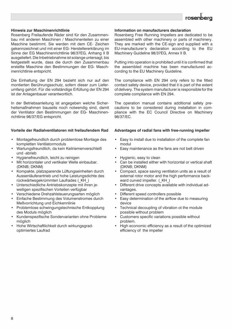
Für genauere Berechnungen bei Schallschutzmaßnah-men ist der Schalleistungspegel der Oktavbänder vonBedeutung.
LWokt = LW(A) + LWrel
Ausführung mit Außenläufermotor:
For the exact determination of the sound protectionrequirement, the sound power level of the octave bandsis important.
LWoct = LW(A) + LWrel
Type with external rotor motor:
DKN_ Eintrittseiteinlet side
Relativer Schalleistungspegel LWrel [dB] bei den Oktavmittenfrequenzen fm [Hz]Relative sound power level LWrel [dB]at octave medium frequenzies fm [Hz]
Baugröße / size 63 125 250 500 1000 2000 4000 8000 Hz
250 / 280 -11 -8 -1 -4 -6 -7 -9 -16 dB
315 / 355 -11 -7 0 -3 -5 -9 -10 -16 dB
400 / 450 -11 -4 0 -3 -5 -8 -12 -18 dB
500 / 560 -10 -3 0 -4 -5 -8 -12 -19 dB
630 -10 -2 1 -5 -5 -7 -12 -19 dB
710 / 800 -3 1 -4 -5 -2 -11 -17 -24 dB
DKN_ Austrittseite / outlet side
250 / 280 -8 -11 -4 -4 -4 -7 -11 -18 dB
315 / 355 -8 -11 -3 -2 -6 -7 -11 -18 dB
400 / 450 -9 -8 -2 -2 -5 -8 -13 -19 dB
500 / 560 -10 -7 -1 -3 -4 -8 -13 -20 dB
630 -10 -3 0 -4 -5 -7 -12 -20 dB
710 / 800 -2 0 -4 -5 -2 -11 -17 -25 dB
Ausführung mit IEC- Normmotor: Type with IEC standard motor:
11
Die angegebenen Relativpegel wurden über einen Kenn-linienbereich von 0,75 bis 1,2 * V opt gemittelt und geltenfür Umfangsgeschwindigkeiten von 25 bis 50 m/s. Bei Be-triebspunkten außerhalb dieses optimalen Einsatzberei-ches sind bei tieferen Frequenzen höhere Abweichungenvon den Tabellenwerten zu erwarten. Die Oktavschallleist-ungspegel können in Einzelfällen im Frequenzbereich desDrehtones höhere Werte erreichen als sie mit Hilfe der Ta-belle errechnet werden.Grundsätzlich ist zu beachten, dass die Geräuschwerteunter Umständen stark von den Einbaubedingungen, Re-flexionen, der vorhandenen Raumakustik und weiterenEinflussfaktoren beeinflusst werden können.
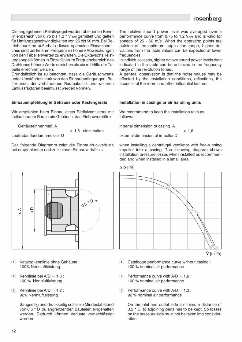
Einbauempfehlung in Gehäuse oder Kastengeräte
Wir empfehlen beim Einbau eines Radialventilators mitfreilaufendem Rad in ein Gehäuse, das Einbauverhältnis
Gehäuseinnenmaß A> 1,6 einzuhalten
Laufradaußendurchmesser D
Das folgende Diagramm zeigt die Einbaudruckverlustebei empfohlenem und zu kleinem Einbauverhältnis.
The relative sound power level was averaged over aperformance curve from 0,75 to 1,2 Vopt and is valid forspeeds of 25 - 50 m/s. When the operating points areoutside of the optimum application range, higher de-viations from the table values can be expected at lowerfrequencies.In individual cases, higher octave sound power levels thanindicated in the table can be achieved in the frequencyrange of the revolution tones .A general observation is that the noise values may beaffected by the installation conditions, reflections, theacoustic of the room and other influential factors.
Installation in casings or air handling units
We recommend to keep the installation ratio asfollows:
internal dimension of casing A> 1,6
external dimension of impeller D
when installing a centrifugal ventilator with free-runningimpeller into a casing. The following diagram showsinstallation pressure losses when installed as recommen-ded and when installed in a small area
Δ p [Pa]
ø D
0,5 * D
A
32
1
32
1
32
1
V [m3/h]
Katalogkennlinie ohne Gehäuse :100% Nennluftleistung
Kennlinie bei A/D = 1,6 :100 % Nennluftleistung
Kennlinie bei A/D = 1,2 :92% Nennluftleistung
Saugseitig und druckseitig sollte ein Mindestabstandvon 0,5 * D zu angrenzenden Bauteilen eingehaltenwerden. Dadurch können Verluste vernachlässigtwerden.
1
2
3
Catalogue performance curve without casing :100 % nominal air performance
Performance curve with A/D = 1,6 :100 % nominal air performance
Performance curve with A/D = 1,2 :92 % nominal air performance
On the inlet and outlet side a minimum distance of0.5 * D to adjoining parts has to be kept. So losseson the pressure side must not be taken into consider-ation.
1
2
3
12

Volumenstrom- MeßeinrichtungDie Volumenstrom-Meßvorrichtung besteht an der An-saugseite aus einer Ringleitung mit drei, beziehungsweisevier in der Einströmdüse (am Ort der stärksten Ein-schnürung) präzise angebrachten Druckentnahmestel-len.Mit Hilfe dieser Meßeinrichtung ist es möglich, den Volu-menstrom in Abhängigkeit des Differenzdrucks zwischendem statischen Druck an der Einströmdüse, und demstatischen Druck im Saugraum vor der Einströmdüse zukontrollieren.Zu beachten ist, daß an der Druckentnahmestelle imSaugraum keine dynamischen Druckanteile mitgemes-sen werden. Die Abnahmebohrungen sind entsprechendauszurichten.Somit ist eine direkte Volumenstrombestimmung, bzw.-überwachung des Ventilators während des Betriebsmöglich. Der Volumenstrom wird nach folgender Be-ziehung errechnet:
Air volume testing deviceThe air volume testing device consists of a circular leadon the inlet side with 3 or 4 pressure measuring devicesincorporated in the inlet cone.
Due to the testing or measuring device it is possible tocontrol the air volume depending on the difference inpressure between the static pressure at the inlet cone andthe static pressure on the inlet side.
Please note that dynamic pressure in the inlet area is notmeasured. The drillings for measurement are to be madeaccordingly.
Due to this a direct control and determination of the airvolume of the fans is possible during operation.
The air volume is calculated according to following for-mula:
V = k •
k = • •α ε A
•
ρ2
• Δp
V Volumenstrom / air volume m³/hk Düsenbeiwert / calibration factor m² s/hρ Gasdichte / density of gas kg/m³Δ Differenzdruck / differential pressure Paα Durchflusszahl / flow factorε Expansionszahl / expansion factorA Düsenquerschnittsfläche an der engsten Stelle
Ring cross section surface at the narrowest point
Durch Prüfstandsmessungen wurde der Düsenbeiwert kfür die einzelnen Baugrößen mit folgender Genauigkeit er-mittelt:
k10 = Abweichung des Volumenstroms kleiner 10%
Testing of each type of fan indicates that the calibrationfactor k for each type of fan is:
k10 = deviation of the airflow smaller than 10%
1 Pressure take-out at inlet cone
2 Circular lead
3 Pressure take-out inlet area
Düsenbeiwerte k10 / Calibration factor k10
Baugröße / size 250 280 315 355 400 450 500 560 630 710 800
k10 E/DKH_ ..... 37 55 70 83 110 134 160 204 278 358 -
k10 GKH_ ..... - 55 70 87 113 145 180 220 - - -
k10 DKN_ ..... 46 55 70 90 113 145 180 220 287 370 475
1 Druckentnahme Düse
2 Ringleitung
3 Druckentnahme Saugraum
13

EKH_ / DKH_
Vorteile:
• kompakte, raumsparende Bauart
• Laufrad mit hoher Leistungsdichte
• hohe Wirtschaftlichkeit durchwirkungsgradoptimiertes Laufrad
• in allen Einbaulagen montierbar
• wartungsfreundlich, da kein Keilriemen-verschleiß und -abrieb
• breites Sortiment von spannungs- undfrequenzsteuerbaren Ausführungen
Advantages:
• compact, space saving construction
• high power impeller
• highly economical because ofhigh efficiency impeller
• installable in all positions
• easy to maintain due to no attrition
• wide range of voltage- andfrequency controllable units

Radialventilatoren mit freilaufendem Rad
Kennliniendarstellung
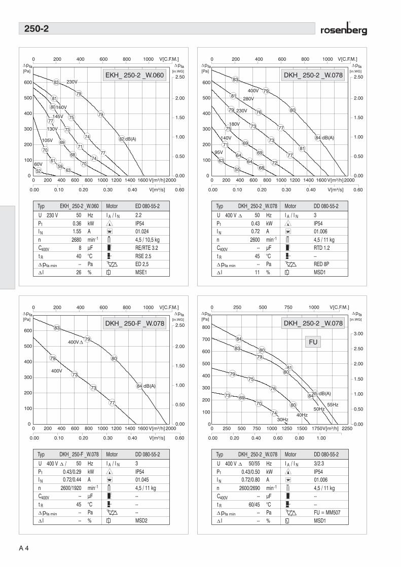
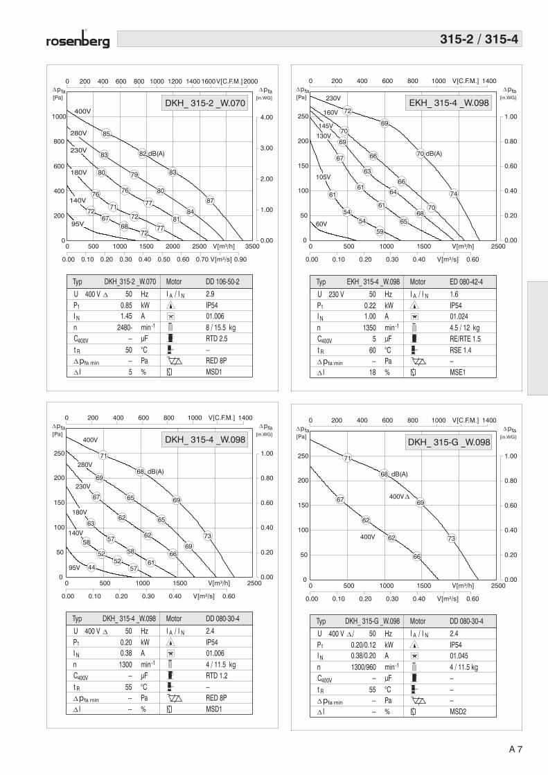
Die Kennliniendarstellung zeigt die statische Drucker-höhung pfa als Funktion des Volumenstroms. Die Kenn-linien beziehen sich auf eine Luftdichte von 1,2 kg/m3.
Radial fans with free-running impeller
Performance Curves
The performance curve indicates the static pressure in-crease pfa as a function of the volume flow. The per-formance curves refer to an air density of 1,2 kg/m3.
Ventilatorkennlinienbei Nenn- und Teil-
spannungenbzw. bei max. Frequenz
und Teilfrequenz
Fan performance curves atrated voltage and
component voltageresp. with max. frequency
and partial frequency
VentilatortypFan type
VentilatornenndatenFan rated data
bei Frequenzsteuerung sinddie Nenndaten für
Maximalfrequenz und 50 HzFrequenz angegeben
with frequency control thenominal data for max. fre-quency and for 50 Hz fre-
quency are stated
TypenbezeichnungType description
Frequenz gesteuertFrequency controlled
Schalleistungspegel LWA8Noise level LWA8
MotortypMotor type
Verhältnis Anlaufstrom zuNenstrom / Ratio of start-ing current to rated current
MotorschutzartMotor protection class
SchaltbildnummerWiring diagram
Gewicht / weightDKHR / DKHM
5-Stufen-Steuergerät5-step controller
0.00
0.50
1.00
1.50
2.00
2.50
3.00
3.50
0
100
200
300
400
500
600
700
800
900
0 1000 2000 3000 4000 5000 6000 7000V[m³/h] 9000
0.00 0.50 1.00 1.50 V[m³/s] 2.50
0 500 1000 1500 2000 2500 3000 3500 4000V[C.F.M.]5000
63Hz
81
76
70
81
78
73
66
80
75
68
87
84
79
72
85
60Hz50Hz
40Hz
30Hz
83 dB(A)
17.5 / 34 kg
IP5401.006
----FU = MM 515MSD1
P1
N
U
InCt
400 V
min-1AkWHz 4/3.5
uF°CPa%
400V
R
1.10/1.762.50/3.00
50/63
--50 / 40
----
I A / I N
Typ
1390/1610
Ipfa min
Motor DD 137-50-4DKH_ 450-4 _W.138
p[Pa]
fa[in.WG]
pfa
DKH_ 450-4 _W.138
FU
Formelzeichen / Technical FormulaBenennung / Designation Einheit / Unit
U Nennspannung / Rated voltage V
P1 Motoraufnahmeleistung / Motor power consumption kW
IN Nennstrom / Rated current A
n Ventilatordrehzahl / Fan speed min-1
C400V Betriebskondensator / Capacitor µF
tR Max. zulässige Fördermitteltemperatur / Max. permissible medium temperature °C
∆ pfamin Statischer Mindestgegendruck / Min. required counter pressure Pa
∆ I Stromanstieg im Teilspannungsbereich / Current increase in partial voltage %
IA / IN Verhältnis Anlaufstrom zu Nennstrom / Ratio of starting current to rated current -
Ausgabe 03/06
Steuergerät stufenlos, transformatorischContinously adjustable controller, transformer type
Steuergerät stufenlos, elektronisch (bei Frequenzumfor-mer wird der Frequenzumformertyp angegeben)
Stepless adjustable, electronic controller (with frequencyconverter use the f.c. type is stated)
Motorschutzschaltgerät / Motor protection unit
Hinweis : Steuergeräte siehe Hauptkatalog Advice : For controllers see basic catalogue
A 1
Eigenschaften und Ausführungen
Die Rosenberg Radialventilatoren mit freilaufendemRad der Baureihen E/DKHR bzw. E/DKHM bilden durchdie Verbindung von Aussenläufermotor und neuent-wickeltem Laufrad eine sehr kompakte, lufttechnisch undkonstruktiv optimale Ventilatoreinheit.Die Kombination von spannungssteuerbarem Rosen-berg-Aussenläufermotor, flexibler Laufradfertigung undleistungsfähiger Blechverarbeitung bietet die MöglichkeitVentilatormodule zu fertigen, die einen größtmöglichenKundennutzen bieten und auf die konstruktiven Be-dürfnisse der Kundenanwendung optimal abgestimmtsind.
Abhängig von der Bauform sind die Ventilatoreinheitenlieferbar als (s. Seite 6):
• E/DKHR : Motorlaufrad ohne oder mit lose beige-fügter Einströmdüse
• E/DKHM: Ventilatoreinbaumodul
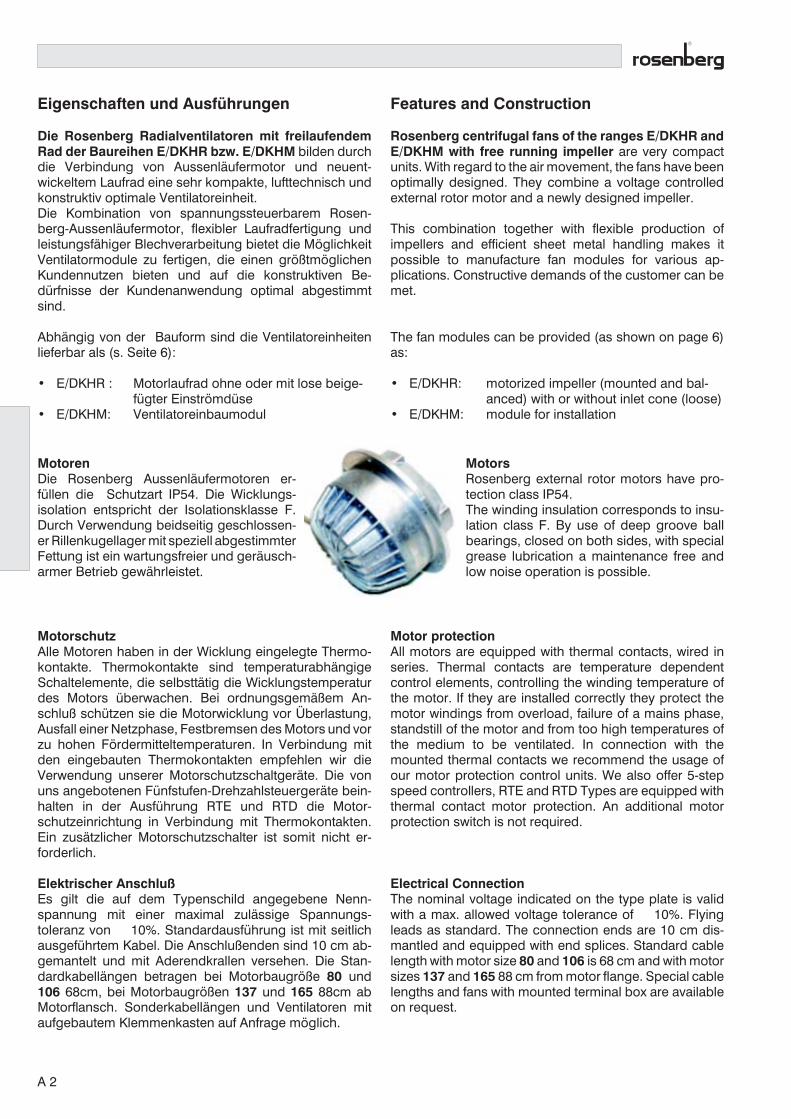
MotorenDie Rosenberg Aussenläufermotoren er-füllen die Schutzart IP54. Die Wicklungs-isolation entspricht der Isolationsklasse F.Durch Verwendung beidseitig geschlossen-er Rillenkugellager mit speziell abgestimmterFettung ist ein wartungsfreier und geräusch-armer Betrieb gewährleistet.
MotorschutzAlle Motoren haben in der Wicklung eingelegte Thermo-kontakte. Thermokontakte sind temperaturabhängigeSchaltelemente, die selbsttätig die Wicklungstemperaturdes Motors überwachen. Bei ordnungsgemäßem An-schluß schützen sie die Motorwicklung vor Überlastung,Ausfall einer Netzphase, Festbremsen des Motors und vorzu hohen Fördermitteltemperaturen. In Verbindung mitden eingebauten Thermokontakten empfehlen wir dieVerwendung unserer Motorschutzschaltgeräte. Die vonuns angebotenen Fünfstufen-Drehzahlsteuergeräte bein-halten in der Ausführung RTE und RTD die Motor-schutzeinrichtung in Verbindung mit Thermokontakten.Ein zusätzlicher Motorschutzschalter ist somit nicht er-forderlich.
Elektrischer AnschlußEs gilt die auf dem Typenschild angegebene Nenn-spannung mit einer maximal zulässige Spannungs-toleranz von ± 10%. Standardausführung ist mit seitlichausgeführtem Kabel. Die Anschlußenden sind 10 cm ab-gemantelt und mit Aderendkrallen versehen. Die Stan-dardkabellängen betragen bei Motorbaugröße 80 und106 68cm, bei Motorbaugrößen 137 und 165 88cm abMotorflansch. Sonderkabellängen und Ventilatoren mitaufgebautem Klemmenkasten auf Anfrage möglich.
Features and Construction
Rosenberg centrifugal fans of the ranges E/DKHR andE/DKHM with free running impeller are very compactunits. With regard to the air movement, the fans have beenoptimally designed. They combine a voltage controlledexternal rotor motor and a newly designed impeller.
This combination together with flexible production ofimpellers and efficient sheet metal handling makes itpossible to manufacture fan modules for various ap-plications. Constructive demands of the customer can bemet.
The fan modules can be provided (as shown on page 6)as:
· E/DKHR: motorized impeller (mounted and bal-anced) with or without inlet cone (loose)
· E/DKHM: module for installation
MotorsRosenberg external rotor motors have pro-tection class IP54.The winding insulation corresponds to insu-lation class F. By use of deep groove ballbearings, closed on both sides, with specialgrease lubrication a maintenance free andlow noise operation is possible.
Motor protectionAll motors are equipped with thermal contacts, wired inseries. Thermal contacts are temperature dependentcontrol elements, controlling the winding temperature ofthe motor. If they are installed correctly they protect themotor windings from overload, failure of a mains phase,standstill of the motor and from too high temperatures ofthe medium to be ventilated. In connection with themounted thermal contacts we recommend the usage ofour motor protection control units. We also offer 5-stepspeed controllers, RTE and RTD Types are equipped withthermal contact motor protection. An additional motorprotection switch is not required.
Electrical ConnectionThe nominal voltage indicated on the type plate is validwith a max. allowed voltage tolerance of ± 10%. Flyingleads as standard. The connection ends are 10 cm dis-mantled and equipped with end splices. Standard cablelength with motor size 80 and 106 is 68 cm and with motorsizes 137 and 165 88 cm from motor flange. Special cablelengths and fans with mounted terminal box are availableon request.
A 2

SpannungsvariantenDie in den Kennlinienfeldern angegebenen Leistungs-daten gelten bei 50Hz für die Standardausführungen 1~230V und 3~ 400V. Motorausführungen für Sonderspann-ungen und Sonderfrequenzen sind auf Anfrage gegenMehrpreis erhältlich. Eine Übersicht über die standard-mäßig verfügbaren 60 Hz-Typen siehe Seite A24 und A25.
DrehzahlsteuerungDie anlagenspezifisch geforderte optimale Einstellungdes gewünschten Betriebspunktes kann nur durch eingeeignetes System zur Drehzahlveränderung realisiertwerden. Für die Drehzahlveränderung können bei dieserVentilatorenbaureihe zwei gängige Systeme verwendetwerden.
- Spannungssteuerung(In der Kennliniendarstellung werden neben der Kennliniebei Nennspannung auch die Teilspannungskennliniendargestellt).Die Drehzahlveränderung erfolgt durch Absenken derangelegten Spannung. Dadurch wird lastabhängig derSchlupf vergrößert und die Drehzahl reduziert. Dergeförderte Volumenstrom ändert sich proportional mit derDrehzahl. Die jeweiligen Spannungssteuergeräte sind imVentilatordatenfeld den Ventilatoren zugeordnet.Alle spannungssteuerbaren Radialventilatoren in Dreh-stromausführung können auch über Frequenzumrichtervon Nennfrequenz abwärts in ihrer Drehzahl verändertwerden.
- Frequenzsteuerung(In der Kennlininedarstellung werden neben den Kenn-linien bei Maximalfrequenz fmax auch die Teilfrequenz-kennlinien dargestellt).Die Drehzahlveränderung erfolgt durch Reduzierung derFrequenz mit einem Frequenzumrichter (FU). Die amFrequenzumrichter einstellbare Eckfrequenz beträgt füralle Ventilatoren 50Hz. Bei Ventilatoren aus der 60Hz-Liste (s. Seite A24/A25) beträgt sie 60Hz. In der Kennlin-iendarstellung ist jeweils die maximal mögliche Frequenzdargestellt. Bei höheren Frequenzen als fmax wird derMotor thermisch überlastet. Für Notbetrieb oder Ausfalldes Frequenzumrichters können alle frequenzsteu-erbaren Typen auch direkt bei 400V am 50Hz-Netzbetrieben werden.
Bei Betrieb der Motoren am Frequenzumrichter darf diemaximale Spannungsanstiegsgeschwindigkeit von 500V/µs nicht überschritten werden. Je nach verwendetemFU und der Leitungslänge zwischen Motor und FU sindZusatzkomponenten vorzusehen.
Voltage typesThe performance data as indicated on the performancecurve charts are for the standard versions at 50 Hz 1~230 V and 3 ~ 400 V. Motors for other voltages or fre-quencies are available on request for additional charge.Please see pages A24 and A25 for 60 Hz standard mo-dels.
Speed controlThe installation-specific optimal adjustment for the re-quired operation point can only be realized with a suitablesystem for speed adjustment. Two common systems canbe used for the speed control of this fan series.
- Voltage control(The performance curves show both nominal voltage andpartial voltage).
The speed control is provided by reduction of the terminalvoltage. So by load-controlled increase of the slippage thespeed is reduced and the air volume flow is reduced inproportion to the speed. The matching voltage controllerscan be found on the fan name plate. All voltagecontrollable centrifugal fans for three-phase current con-struction can also be speed controlled by frequencyconverter from rated frequency downwards.
- Frequency control(The performance curves show both maximum frequencyfmax and partial frequency).The speed control is provided by reduction of thefrequency. The cut-off frequency adjustable on thefrequency converter is 50Hz for all fans. The maximumfrequency adjustable on the frequency converter is 50 Hzrespectively 60 Hz for 60 Hz models pages A 24 and A 25.Each performance curve shows the max. possiblefrequency. With higher frequencies than the rated fre-quency the motor will thermally overload. In case ofemergency service or failure of the frequency converterall frequency controllable types can be used also directwith 400V on the 50 Hz mains supply.
With operation of the motors on a frequency controller themax. speed of voltage increase of 500 V/µs must not beexceeded. According to the frequency converter type andthe length of the cable between motor and frequencyconverter additional components may be required.
A 3
0 200 400 600 800 1000 1200 1400 1600 V[m³/h]2000
0.00 0.10 0.20 0.30 0.40 V[m³/s] 0.60
0 200 400 600 800 1000 V[C.F.M.]
0
100
200
300
400
500
600
0.00
0.50
1.00
1.50
2.00
2.50
60V
83
81
80
77
70
52
79
75
73
69
61
79
74
71
68
59
7774
7063
230V
160V
145V
130V
105V 82 dB(A)
EKH_ 250-2 _W.060
p[Pa]
fa[in.WG]
pfa
4,5 / 10,5 kg
IP5401.024
RE/RTE 3.2RSE 2.5ED 2,5MSE1
P1
N
U
InCt
230 V
min-1AkWHz 2.2
uF°CPa%
400V
R
0.361.55
50
840--
26
I A / I N
EKH_ 250-2 _W.060Typ
2680
Ipfa min
Motor ED 080-55-2
0 200 400 600 800 1000 1200 1400 1600 V[m³/h]2000
0.00 0.10 0.20 0.30 0.40 V[m³/s] 0.60
0 200 400 600 800 1000 V[C.F.M.]
0
100
200
300
400
500
600
0.00
0.50
1.00
1.50
2.00
2.50
95V
83
81
79
75
71
63
79
76
73
69
64
80
77
73
69
64
55
84 dB(A)
8177
7268
400V
280V
230V
180V
140V
p[Pa]
fa[in.WG]
pfa
4,5 / 11 kg
IP5401.006
RTD 1.2--RED 8PMSD1
P1
N
U
InCt
400 V
min-1AkWHz 3
uF°CPa%
400V
R
0.430.72
50
--45--
11
I A / I N
Typ
2600
Ipfa min
Motor DD 080-55-2DKH_ 250-2 _W.078
DKH_ 250-2 _W.078
0 200 400 600 800 1000 1200 1400 1600 V[m³/h]2000
0.00 0.10 0.20 0.30 0.40 V[m³/s] 0.60
0 200 400 600 800 1000 V[C.F.M.]
0
100
200
300
400
500
600
0.00
0.50
1.00
1.50
2.00
2.5083
79
80
84 dB(A)
400V Y
400V
79
73
73
77
p[Pa]
fa[in.WG]
pfa
4,5 / 11 kg
IP5401.045
------MSD2
P1
N
U
InCt
400 V / Y
min-1AkWHz 3
uF°CPa%
400V
R
0.43/0.290.72/0.44
50
--45----
I A / I N
Typ
2600/1920
Ipfa min
Motor DD 080-55-2DKH_ 250-F _W.078
DKH_ 250-F _W.078
250-2
0
100
200
300
400
500
600
700
800
0.00
0.50
1.00
1.50
2.00
2.50
3.00
0 250 500 750 1000 1250 1500 1750V[m³/h] 2250
0.00 0.20 0.40 0.60 0.80 1.00
0 250 500 750 1000 V[C.F.M.]
84
83
79
73
8079
75
69
8180
76
70
85 dB(A)84
80
74
55Hz50Hz
40Hz30Hz
4,5 / 11 kg
IP5401.006
----FU = MM507MSD1
P1
N
U
InCt
400 V
min-1AkWHz 3/2.3
uF°CPa%
400V
R
0.43/0.500.72/0.80
50/55
--60/45
----
I A / I N
Typ
2600/2690
Ipfa min
Motor DD 080-55-2DKH_ 250-2 _W.078
p[Pa]
fa[in.WG]
pfa
DKH_ 250-2 _W.078
FU
A 4

0 500 1000 1500 2000 V[m³/h] 3000
0.00 0.10 0.20 0.30 0.40 0.50 0.60 V[m³/s] 0.80
0 200 400 600 800 1000 1200 1400V[C.F.M.]1800
0
100
200
300
400
500
600
700
800
0.00
0.50
1.00
1.50
2.00
2.50
3.00
230V
60V
160V
145V
130V
105V
84
80
82
86
80
76
75 dB(A)
81
80
73
74
7774
70
69
77
71
6463
6748
p[Pa]
fa[in.WG]
pfa
7,5 / 18 kg
IP5401.024
RE/RTE 5RSE 5.5ED 5,0MSE1
P1
N
U
InCt
230 V
min-1AkWHz 2.2
uF°CPa%
400V
R
0.773.40
50
1440--
13
I A / I N
EKH _ 280-2 W.087Typ
2520
Ipfa min
Motor ED 106-50-2
EKH_ 280-2 _W.087
0 500 1000 1500 2000 V[m³/h] 3000
0.00 0.10 0.20 0.30 0.40 0.50 0.60 V[m³/s] 0.80
0 200 400 600 800 1000 1200 1400V[C.F.M.]1800
0
100
200
300
400
500
600
700
800
0.00
0.50
1.00
1.50
2.00
2.50
3.00
p[Pa]
fa[in.WG]
pfa
400V
95V
83
80
78
74
69
60
79
75
72
68
63
81
75
74
7063
55
85
7978
7368
280V
230V
180V
140V
6.5 / 17 kg
IP5401.006
RTD 1.2--RED 8PMSD1
P1
N
U
InCt
400 V
min-1AkWHz 2.7
uF°CPa%
400V
R
0.661.10
50
--50----
I A / I N
Typ
2400
Ipfa min
Motor DD 106-35-2DKH_ 280-2 _W.087
DKH_ 280-2 _W.087
0 500 1000 1500 2000 V[m³/h] 3000
0.00 0.10 0.20 0.30 0.40 0.50 0.60 V[m³/s] 0.80
0 200 400 600 800 1000 1200 1400V[C.F.M.]1800
0
100
200
300
400
500
600
700
800
0.00
0.50
1.00
1.50
2.00
2.50
3.00
p[Pa]
fa[in.WG]
pfa
83
79
85
81
6.5 / 17 kg
IP5401.045
------MSD2
P1
N
U
InCt
400 V / Y
min-1AkWHz 2.7
uF°CPa%
400V
R
0.66/0.401.10/0.60
50
--50----
I A / I N
Typ
2400/1720
Ipfa min
Motor DD 106-35-2
78
72
74
78
400V Y
400V
DKH_ 280-F _W.087
DKH_ 280-F _W.087
280-2
0.00
1.00
2.00
3.00
4.00
0
200
400
600
800
1000
0 500 1000 1500 2000 2500 V[m³/h] 3500
0.00 0.10 0.20 0.30 0.40 0.50 0.60 0.70 V[m³/s] 0.90
0 200 400 600 800 1000 1200 1400 1600V[C.F.M.]2000
87
85
84
80
74
8281
80
76
70
8483
82
78
72
88 dB(A)8786
82
76
7.5 / 18 kg
IP5401.006
----FU = MM507MSD1
P1
N
U
InCt
400 V
min-1AkWHz 2.6/2.6
uF°CPa%
400V
R
0.90/1.051.30/1.60
50/60
--60/40
----
I A / I N
Typ
2600/2810
Ipfa min
Motor DD 106-50-2DKH_ 280-2 _W.87
p[Pa]
fa[in.WG]
pfa
50Hz
40Hz
60Hz
30Hz
55Hz
DKH_ 280-2 _W.087
FU
A 5

60V
0 500 1000 1500 2000 2500 3000 3500 V[m³/h] 4500
0.00 0.20 0.40 0.60 0.80 V[m³/s] 1.20
0 500 1000 1500 V[C.F.M.] 2500
0
200
400
600
800
1000
0.00
0.50
1.00
1.50
2.00
2.50
3.00
3.50
4.00
p[Pa]
fa[in.WG]
pfa
15 / 26 kg
IP5401.024
RE/RTE 7.5----MSE1
P1
N
U
InCt
230 V
min-1AkWHz 1.5
uF°CPa%
400V
R
1.506.70
50
2550--
11
I A / I N
Typ
2610
Ipfa min
Motor ED 137-50-2
86
84
81
77
71
52
83
78
74
72
64
77
7372
63
88
8177
7467
84 dB(A)
230V
160V
145V
130V
105V
EKH_ 315-2 _W.098
EKH_ 315-2 _W.098
0 500 1000 1500 2000 2500 3000 3500 V[m³/h] 4500
0.00 0.20 0.40 0.60 0.80 V[m³/s] 1.20
0 500 1000 1500 V[C.F.M.] 2500
0
200
400
600
800
1000
0.00
0.50
1.00
1.50
2.00
2.50
3.00
3.50
4.00
86
84
81
76
71
64
83
79
76
71
66
84 dB(A)
80
76
7166
58
88
8480
7570
400V
280V
230V
180V
140V
95V
p[Pa]
fa[in.WG]
pfa
12 / 23 kg
IP5401.006
RTD 2,5--RED 8PMSD1
P1
N
U
InCt
400 V
min-1AkWHz 2.6
uF°CPa%
400V
R
1.302.20
50
--40--3
I A / I N
Typ
2550
Ipfa min
Motor DD 137-35-2DKH_ 315-2 _W.098
DKH_ 315-2 _W.098
0 500 1000 1500 2000 2500 3000 3500 V[m³/h] 4500
0.00 0.20 0.40 0.60 0.80 V[m³/s] 1.20
0 500 1000 1500 V[C.F.M.] 2500
0
200
400
600
800
1000
0.00
0.50
1.00
1.50
2.00
2.50
3.00
3.50
4.00
86
83
76
84 dB(A)
76
88
80
81
400V Y
400V
p[Pa]
fa[in.WG]
pfa
12 / 23 kg
IP5401.045
------MSD2
P1
N
U
InCt
400 V / Y
min-1AkWHz 2.6
uF°CPa%
400V
R
1.30/0.802.20/1.30
50
--40----
I A / I N
Typ
2550/1750
Ipfa min
Motor DD 137-35-2DKH_ 315-F _W.098
DKH_ 315-F _W.098
315-2
0
200
400
600
800
1000
1200
1400
1600
0.00
1.00
2.00
3.00
4.00
5.00
6.00
0 500 1000 1500 2000 V[C.F.M.] 3000
0 500 1000 1500 2000 2500 3000 3500 4000V[m³/h]5000
0.00 0.20 0.40 0.60 0.80 1.00 V[m³/s] 1.40
15 / 26 kg
IP5401.006
RTD 2.5--FU = MM 515MSD1
P1
N
U
InCt
400 V
min-1AkWHz 4.2/3.2
uF°CPa%
400V
R
1.4/2.12.5/3.4
50/60
--70/40
----
I A / I N
Typ
2750/3060
Ipfa min
Motor DD 137-50-2DKH_ 315-2 _W.098
p[Pa]
fa[in.WG]
pfa
90
89
87
82
76
8685
83
77
72
8685
84
80
74
908988
84
78
55Hz
40Hz
30Hz
50Hz
60Hz
DKH_ 315-2 _W.098
FU
A 6
0.00
1.00
2.00
3.00
4.00
0
200
400
600
800
1000
0 500 1000 1500 2000 2500 V[m³/h] 3500
0.00 0.10 0.20 0.30 0.40 0.50 0.60 0.70 V[m³/s] 0.90
0 200 400 600 800 1000 1200 1400 1600V[C.F.M.]2000p
[Pa]fa
[in.WG]
pfa
400V
85
80
76
77
6881
7767
76
7172
72
72
83
87
82 dB(A)
8 / 15.5 kg
IP5401.006
RTD 2.5--RED 8PMSD1
P1
N
U
InCt
400 V
min-1AkWHz 2.9
uF°CPa%
400V
R
0.851.45
50
--50--5
I A / I N
Typ
2480-
Ipfa min
Motor DD 106-50-2DKH_315-2 _W.070
DKH_ 315-2 _W.070
230V
180V
140V
95V
280V
83
79
80
84
0 500 1000 1500 V[m³/h] 2500
0.00 0.10 0.20 0.30 0.40 V[m³/s] 0.60
0 200 400 600 800 1000 V[C.F.M.] 1400
0
50
100
150
200
250
0.00
0.20
0.40
0.60
0.80
1.00
230V
60V
160V
p[Pa]
fa[in.WG]
pfa
4.5 / 12 kg
IP5401.024
RE/RTE 1.5RSE 1.4--MSE1
P1
N
U
InCt
230 V
min-1AkWHz 1.6
uF°CPa%
400V
R
0.221.00
50
560--
18
I A / I N
Typ
1350
Ipfa min
Motor ED 080-42-4EKH_ 315-4 _W.098
EKH_ 315-4 _W.09872
70
69
67
61
69
66
63
61
54
70 dB(A)
66
64
61
54
74
7068
65
59
145V
130V
105V
0 500 1000 1500 V[m³/h] 2500
0.00 0.10 0.20 0.30 0.40 V[m³/s] 0.60
0 200 400 600 800 1000 V[C.F.M.] 1400
0
50
100
150
200
250
0.00
0.20
0.40
0.60
0.80
1.00
400V
95V
p[Pa]
fa[in.WG]
pfa
4 / 11.5 kg
IP5401.006
RTD 1.2--RED 8PMSD1
P1
N
U
InCt
400 V
min-1AkWHz 2.4
uF°CPa%
400V
R
0.200.38
50
--55----
I A / I N
Typ
1300
Ipfa min
MotorDKH_ 315-4 _W.098
DKH_ 315-4 _W.098
71
69
67
63
58
68 dB(A)
65
62
57
52
44
69
65
62
58
52
73
6966
6157
280V
180V
140V
230V
DD 080-30-4
0 500 1000 1500 V[m³/h] 2500
0.00 0.10 0.20 0.30 0.40 V[m³/s] 0.60
0 200 400 600 800 1000 V[C.F.M.] 1400
0
50
100
150
200
0.00
0.20
0.40
0.60
0.80
1.00
400V Y
400V
250
p[Pa]
fa[in.WG]
pfa
4 / 11.5 kg
IP5401.045
------MSD2
P1
N
U
InCt
min-1AkWHz 2.4
uF°CPa%
400V
R
0.20/0.120.38/0.20
50
--55----
I A / I N
Typ
1300/960
Ipfa min
Motor DD 080-30-4
400 V / Y
DKH_ 315-G _W.098
DKH_ 315-G _W.098
71
67
68 dB(A)
62
69
62 73
66
315-2 / 315-4
A 7

0 1000 2000 3000 4000 V[m³/h] 6000
0.00 0.20 0.40 0.60 0.80 1.00 1.20 1.40 V[m³/s] 1.80
0 500 1000 1500 2000 2500 V[C.F.M.] 3500
0
200
400
600
800
1000
1200
1400
0.00
1.00
2.00
3.00
4.00
5.00
400V
95V
90
89
87
85
80
72
89
87
85
81
77
69
88
85
82
77
69
94
9289
8681
73
280V
230V
180V
140V
90 dB(A)
p[Pa]
fa[in.WG]
pfa
20 / 31 kg
IP5401.006
RTD 5--RED 8PMSD1
P1
N
U
InCt
400 V
min-1AkWHz 3
uF°CPa%
400V
R
2.354.0
50
--45--6
I A / I N
Typ
2650
Ipfa min
Motor DD 137-75-2DKH_ 355-2 _W.110
DKH_ 355-2 _W.110
0 1000 2000 3000 4000 V[m³/h] 6000
0.00 0.20 0.40 0.60 0.80 1.00 1.20 1.40 V[m³/s] 1.80
0 500 1000 1500 2000 2500 V[C.F.M.] 3500
0
200
400
600
800
1000
1200
0.00
1.00
2.00
3.00
4.00
5.0090
89
94
90 dB(A)87
85
85
89
400V Y
1400
p[Pa]
fa[in.WG]
pfa
20 / 31 kg
IP5401.045
------MSD2
P1
N
U
InCt
400 V / Y
min-1AkWHz 3
uF°CPa%
400V
R
2.35/1.504.0/2.5
50
--45----
I A / I N
Typ
2650/2050
Ipfa min
Motor DD 137-75-2
400V
DKH_ 355-F _W.110
DKH_ 355-F _W.110
0
200
400
600
800
1000
1200
1400
1600
0.00
1.00
2.00
3.00
4.00
5.00
6.00
0 500 1000 1500 2000 2500 V[C.F.M.] 3500
0 1000 2000 3000 4000 V[m³/h] 6000
0.00 0.20 0.40 0.60 0.80 1.00 1.20 V[m³/s] 1.60
52Hz
30Hz
90
85
80
89
85
79
90
86
80
94
90 dB(A)
84
91
50Hz
40Hz
20 / 31 kg
IP5401.006
----FU = MM 522MSD1
P1
N
U
InCt
400 V
min-1AkWHz 3
uF°CPa%
400V
R
2.35/2.554.00/4.25
50/52
--45/40
----
I A / I N
Typ
2650/2710
Ipfa min
Motor DD 137-75-2DKH_ 355-2 _W.110
p[Pa]
fa[in.WG]
pfa
DKH_355-2 _W.110
FU
355-2
A 8
0 500 1000 1500 2000 2500 V[m³/h] 3500
0.00 0.10 0.20 0.30 0.40 0.50 0.60 0.70 0.80 V[m³/s] 1.00
0 200 400 600 800 1000 1200 1400 1600 V[C.F.M.]
0
50
100
150
200
250
300
350
0.00
0.20
0.40
0.60
0.80
1.00
1.20
1.40230V
60V
p[Pa]
fa[in.WG]
pfa
5.5 / 16.5 kg
IP5401.024
RE/RTE 3.2RSE 2.5ED 2,5MSE1
P1
N
U
InCt
230 V
min-1AkWHz 2
uF°CPa%
400V
R
0.321.40
50
650--
18
I A / I N
Typ
1300
Ipfa min
Motor ED 080-55-4EKH_ 355-4 _W.110
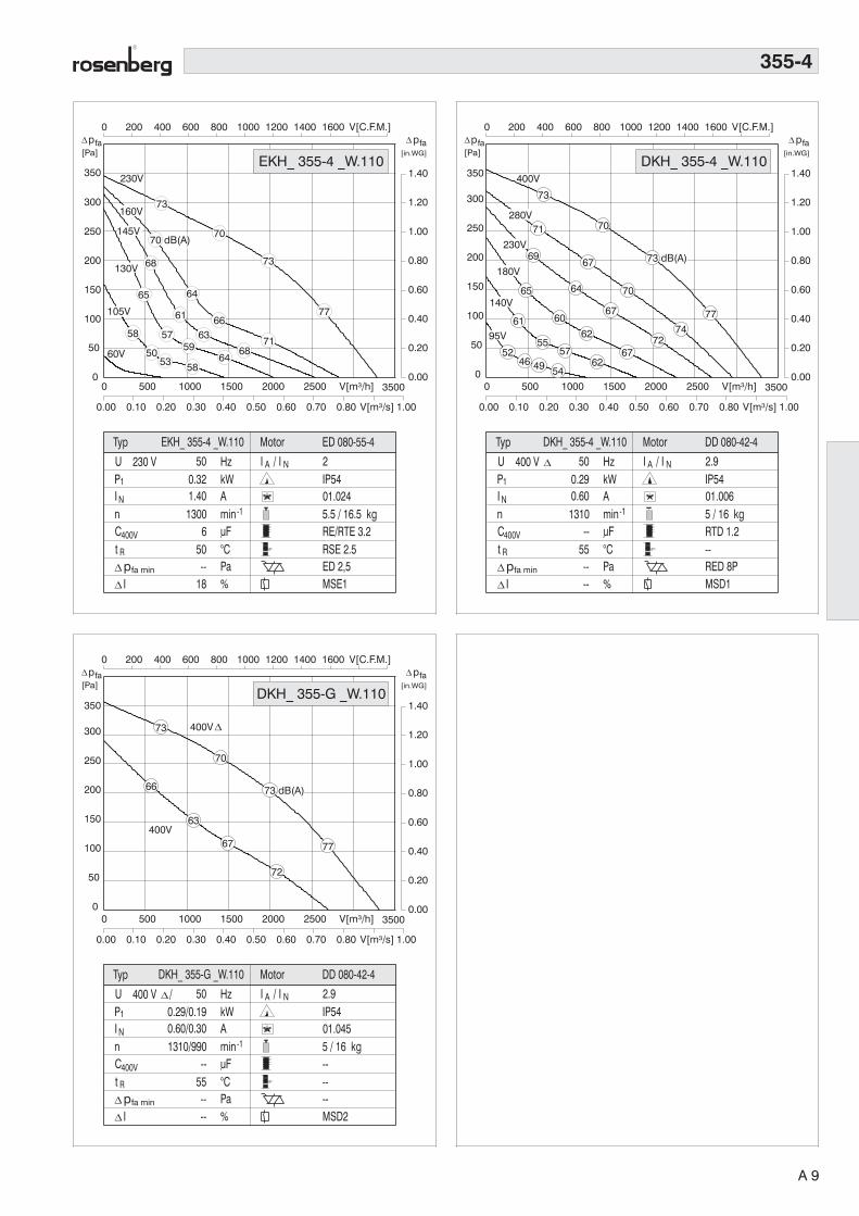
EKH_ 355-4 _W.110
73
68
65
58
70
64
61
57
50
73
6663
5953
77
7168
6458
145V
160V
130V
105V
70 dB(A)
0 500 1000 1500 2000 2500 V[m³/h] 3500
0.00 0.10 0.20 0.30 0.40 0.50 0.60 0.70 0.80 V[m³/s] 1.00
0 200 400 600 800 1000 1200 1400 1600 V[C.F.M.]
0
50
100
150
200
250
300
350
0.00
0.20
0.40
0.60
0.80
1.00
1.20
1.40
73
71
69
65
61
52
70
67
64
60
55
46
70
67
62
5749
7774
7267
6254
73 dB(A)
280V
230V
180V
140V
95V
p[Pa]
fa[in.WG]
pfa
5 / 16 kg
IP5401.006
RTD 1.2--RED 8PMSD1
P1
N
U
InCt
400 V
min-1AkWHz 2.9
uF°CPa%
400V
R
0.290.60
50
--55----
I A / I N
Typ
1310
Ipfa min
Motor DD 080-42-4
400V
DKH_ 355-4 _W.110
DKH_ 355-4 _W.110
0 500 1000 1500 2000 2500 V[m³/h] 3500
0.00 0.10 0.20 0.30 0.40 0.50 0.60 0.70 0.80 V[m³/s] 1.00
0 200 400 600 800 1000 1200 1400 1600 V[C.F.M.]
0
50
100
150
200
250
300
0.00
0.20
0.40
0.60
0.80
1.00
1.20
1.40
73
70
77
73 dB(A)66
63
67
72
400V Y
400V
350
p[Pa]
fa[in.WG]
pfa
5 / 16 kg
IP5401.045
------MSD2
P1
N
U
InCt
min-1AkWHz 2.9
uF°CPa%
400V
R
0.29/0.190.60/0.30
50
--55----
I A / I N
Typ
1310/990
Ipfa min
Motor DD 080-42-4
400 V / Y
DKH_ 355-G _W.110
DKH_ 355-G _W.110
355-4
A 9

0 500 1000 1500 2000 2500 3000 3500 4000 4500 V[m³/h]
0.00 0.20 0.40 0.60 0.80 1.00 1.20 V[m³/s] 1.60
0 500 1000 1500 2000 V[C.F.M.] 3000
0
200
400
600
800
1000
1200
1400
1600
1800
0.00
1.00
2.00
3.00
4.00
5.00
6.00
7.00400V
230V
140V
20 / 31 kg
IP5401.006
RTD 5--RED 8PMSD1
P1
N
U
InCt
400 V
min-1AkWHz 3
uF°CPa%
400V
R
2.354.0
50
--45--6
I A / I N
Typ
2650
Ipfa min
Motor DD 137-75-2DKH_ 400-2 _W.065
p[Pa]
fa[in.WG]
pfa
DKH_400-2 _W.065
92
90
89
85
81
73
89
87
84
80
76
68
89
86
84
80
75
67
8886
8278
69
280V
180V
95V
91 dB(A)
0 500 1000 1500 2000 2500 3000 3500 4000 4500 V[m³/h]
0.00 0.20 0.40 0.60 0.80 1.00 1.20 V[m³/s] 1.60
0 500 1000 1500 2000 V[C.F.M.] 3000
0
200
400
600
800
1000
1200
1400
1600
1800
0.00
1.00
2.00
3.00
4.00
5.00
6.00
7.00
p[Pa]
fa[in.WG]
pfa
400V
20 / 31 kg
IP5401.045
------MSD2
P1
N
U
InCt
400 V / Y
min-1AkWHz 3
uF°CPa%
400V
R
2.35/1.54.0/2.5
50
--45----
I A / I N
Typ
2650/2040
Ipfa min
Motor DD 137-75-2DKH_ 400-F _W.065
DKH_400-F _W.065
400V Y
92
89
89
84
89
84
86
91 dB(A)
0.00
1.00
2.00
3.00
4.00
5.00
6.00
7.00
0
200
400
600
800
1000
1200
1400
1600
1800
0 500 1000 1500 2000 V[C.F.M.] 3000
0 500 1000 1500 2000 2500 3000 3500 4000V[m³/h]5000
0.00 0.20 0.40 0.60 0.80 1.00 V[m³/s] 1.40
52Hz
30Hz
89
88
86
84
82
89
85
83
91 dB(A)
87
85
93
88
50Hz
40Hz
20 / 31 kg
IP5401.006
----FU = MM 522MSD1
P1
N
U
InCt
400 V
min-1AkWHz 3/3
uF°CPa%
400V
R
2.35/2.554.0/4.25
50/52
--45/40
----
I A / I N
Typ
2650/2700
Ipfa min
Motor DD 137-75-2DKH_ 400-2 _W.065
p[Pa]
fa[in.WG]
pfa
DKH_ 400-2 _W.065
FU
400-2
A 10

0 500 1000 1500 2000 2500 3000 3500 4000V[m³/h]5000
0.00 0.20 0.40 0.60 0.80 1.00 V[m³/s] 1.40
0 500 1000 1500 2000 V[C.F.M.] 3000
0
50
100
150
200
250
300
350
400
450
0.00
0.20
0.40
0.60
0.80
1.00
1.20
1.40
1.60
1.80
230V
60V
105V
p[Pa]
fa[in.WG]
pfa
12 / 20 kg
IP5401.024
RE/RTE 3.2RSE 3.7ED 5,0MSE1
P1
N
U
InCt
230 V
min-1AkWHz 2.3
uF°CPa%
400V
R
0.602.80
50
1240--
12
I A / I N
Typ
1350
Ipfa min
Motor ED 106-50-4EKH_ 400-4 _W.123
EKH_ 400-4 _W.12377
75
73
70
63
74
70
66
63
55
76
71
67
64
57
80
7572
6861
145V
130V
160V
0 500 1000 1500 2000 2500 3000 3500 4000V[m³/h]5000
0.00 0.20 0.40 0.60 0.80 1.00 V[m³/s] 1.40
0 500 1000 1500 2000 V[C.F.M.] 3000
0
50
100
150
200
250
300
350
400
450
0.00
0.20
0.40
0.60
0.80
1.00
1.20
1.40
1.60
1.80400V
95V
77
75
74
70
65
57
74
72
69
65
60
51
73
71
67
62
53
80
7875
7166
57
280V
230V
180V
140V
76 dB(A)
p[Pa]
fa[in.WG]
pfa
12 / 20 kg
IP5401.006
RTD 2.5--RED 8PMSD1
P1
N
U
InCt
400 V
min-1AkWHz 3.1
uF°CPa%
400V
R
0.541.15
50
--60----
I A / I N
Typ
1340
Ipfa min
Motor DD 106-50-4DKH_ 400-4 _W.123
DKH_ 400-4 _W.123
0 500 1000 1500 2000 2500 3000 3500 4000V[m³/h]5000
0.00 0.20 0.40 0.60 0.80 1.00 V[m³/s] 1.40
0 500 1000 1500 2000 V[C.F.M.] 3000
0
50
100
150
200
250
300
350
400
0.00
0.20
0.40
0.60
0.80
1.00
1.20
1.40
1.60
1.80
400V Y
400V
450
p[Pa]
fa[in.WG]
pfa
12 / 20 kg
IP5401.045
------MSD2
P1
N
U
InCt
400 V / Y
min-1AkWHz 3.1
uF°CPa%
400V
R
0.54/0.351.15/0.65
50
--60----
I A / I N
Typ
1340/1050
Ipfa min
Motor DD 106-50-4DKH_ 400-G _W.123
DKH_ 400-G _W.123
77
74
74
69
71 80
75
76 dB(A)
400-4
A 11

pfa[in.WG]
0 500 1000 1500 2000 2500 3000 V[C.F.M.] 4000
0.00
0.50
1.00
1.50
2.50
230V
60V
160V
pfa[Pa]
12 / 30 kg
IP5401.024
RE/RTE 5RSE 5.5ED 5,0MSE1
P1
N
U
InCt
230 V
min-1AkWHz 1.9
uF°CPa%
400V
R
0.82
pfa[in.WG]
0 500 1000 1500 2000 2500 3000 V[C.F.M.] 4000
0.00
0.50
1.00
1.50
2.50
pfa[Pa]
0 1000 2000 3000 4000 5000 V[m³/h] 7000
0.00 0.20 0.40 0.60 0.80 1.00 1.20 1.40 V[m³/s] 1.80
0
100
200
300
400
600
95V
400V
12 / 30 kg
IP5401.006
RTD 2.5--RED 8PMSD1
P1
N
U
InCt
400 V
min-1AkWHz 3.3
uF°CPa%
400V
R
0.911.65
50
--45--8
I A / I N
Typ
1300
Ipfa min
Motor DD 106-70-4DKH_ 450-4 _W.138
DKH_ 450-4 _W.138
80
78
76
73
68
77
74
72
67
62
79 dB(A)
76
73
68
63
83
8077
7368
140V180V
230V280V
400V
400V Y
12 / 30 kg
IP5401.045
------MSD 2
P1
N
U
InCt
400 V / Y
min-1AkWHz 3.3
uF°CPa%
400V
R
0.91/0.581.65/1.0
50
--45----
I A / I N
Typ Motor DD 106-70-4
1300/980
Ipfa min
DKH_ 450-G _W.138
pfa[in.WG]
0 500 1000 1500 2000 2500 3000 V[C.F.M.] 4000
0.00
0.50
1.00
1.50
2.50
pfa[Pa]
0 1000 2000 3000 4000 5000 V[m³/h] 7000
0.00 0.20 0.40 0.60 0.80 1.00 1.20 1.40 V[m³/s] 1.80
0
100
200
300
400
600
80
76
77
72
79 dB(A)
73 83
77
DKH_ 450-G _W.138
450-4
0.00
0.50
1.00
1.50
2.00
2.50
3.00
3.50
0
100
200
300
400
500
600
700
800
900
0 1000 2000 3000 4000 5000 6000 7000V[m³/h] 9000
0.00 0.50 1.00 1.50 V[m³/s] 2.50
0 500 1000 1500 2000 2500 3000 3500 4000V[C.F.M.]5000
63Hz
81
76
70
81
78
73
66
80
75
68
87
84
79
72
85
60Hz50Hz
40Hz
30Hz
83 dB(A)
17.5 / 34 kg
IP5401.006
----FU = MM 515MSD1
P1
N
U
InCt
400 V
min-1AkWHz 4/3.5
uF°CPa%
400V
R
1.10/1.762.50/3.00
50/63
--50 / 40
----
I A / I N
Typ
1390/1610
Ipfa min
Motor DD 137-50-4DKH_ 450-4 _W.138
p[Pa]
fa[in.WG]
pfa
DKH_ 450-4 _W.138
FU
A 12

0 500 1000 1500 2000 V[C.F.M.] 3000
0.00
0.20
0.40
0.60
0.80
1.20
pfa[in.WG]
130V60V
72
7170
68
63
46
69
66
65
61
54
71
67
65
61
53
7270
66
57
230V160V
145V
105V
75 dB(A)
DKH_ 450-4 _W.140
0 500 1000 1500 2000 2500 3000 3500 4000V[m³/h] 5000
0.00 0.20 0.40 0.60 0.80 1.00 V[m³/s] 1.40
0
50
100
150
200
300
pfa[Pa]
9.5 / 28 kg
IP5401.024
RE/RTE 3.2RSE 2.5--MSE1
P1
N
U
InCt
230 V
min-1AkWHz 2.4
uF°CPa%
400V
R
0.371.9
50
640--
23
I A / I N
Typ
910
Ipfa min
Motor ED 106-50-6EKH_ 450-6 _W.138
EKH_ 450-6 _W.138
0 500 1000 1500 2000 V[C.F.M.] 3000
0.00
0.20
0.40
0.60
0.80
1.20
pfa[in.WG]
95V
71
69
67
63
59
51
68
65
63
59
56
48
70
68
65
60
56
48
7169
6458
50
400V280V
230V180V
140V
74 dB(A)
0 500 1000 1500 2000 2500 3000 3500 4000 [m³/h] 5000
0.00 0.20 0.40 0.60 0.80 1.00 V[m³/s] 1.40
0
50
100
150
200
300
pfa[Pa]
8.5 / 27 kg
IP5401.006
RTD 1.2--RED 8PMSD1
P1
N
U
InCt
400 V
min-1AkWHz 2.6
uF°CPa%
400V
R
0.310.64
50
--70----
I A / I N
Typ
880
Ipfa min
Motor DD 106-35-6DKH_ 450-6 _W.138
DKH_ 450-6 _W.138
0 500 1000 1500 2000 V[C.F.M.] 3000
0.00
0.20
0.40
0.60
0.80
1.20
pfa[in.WG]
68
400V
400V Y
DKH_ 450-H _W.138
0 500 1000 1500 2000 2500 3000 3500 4000V[m³/h] 5000
0.00 0.20 0.40 0.60 0.80 1.00 V[m³/s] 1.40
0
50
100
150
200
300
pfa[Pa]
8.5 / 27 kg
IP5401.045
------MSD2
P1
N
U
InCt
400 V / Y
min-1AkWHz 2.6
uF°CPa%
400V
R
0.31/0.20.64/0.34
50
--70----
I A / I N
Typ
880/675
Ipfa min
Motor DD 106-35-6DKH_ 450-H _W.138
71
67
68
63
70
65
69
74 dB(A)
450-6
A 13

0 1000 2000 3000 4000 5000 6000 7000 V[m³/h] 9000
0.00 0.50 1.00 1.50 V[m³/s] 2.50
0 500 1000 1500 2000 2500 3000 3500 4000 4500 V[C.F.M.]
0
100
200
300
400
500
600
800
0.00
0.50
1.00
1.50
2.00
3.00
83
81
79
77
72
80
75
72
70
64
82
7673
70
64
86 dB(A)
8077
7467
230V
160V145V
130V105V60V
21.5 / 39 kg
IP5401.024
RE/RTE 10----MSE1 3,6kW
P1
N
U
InCt
230 V
min-1AkWHz 2.2
uF°CPa%
400V
R
1.77.5
50
3040--7
I A / I N
EKH_ 500-4 _W.155Typ
1290
EKH_ 500-4 _W.155p[Pa]
fa
[in.WG]
pfa
Ipfa min
Motor ED 137-75-4
0 1000 2000 3000 4000 5000 6000 7000 8000V[m³/h]10000
0.00 0.50 1.00 1.50 2.00 V[m³/s] 3.00
0 1000 2000 3000 4000 V[C.F.M.] 6000
0
100
200
300
400
500
600
800
0.00
0.50
1.00
1.50
2.00
3.00
95V
84
83
82
80
77
70
81
79
78
75
72
65
83
81
79
76
73
65
8584
81
77
69
21.5 / 39 kg
IP5401.006
RTD 5--RED 8PMSD1
P1
N
U
InCt
400 V
min-1AkWHz 4.0
uF°CPa%
400V
R
1.83.5
50
--55--
11
I A / I N
Typ
1380
p[Pa]
fa
[in.WG]
pfa
Ipfa min
400V280V
230V180V
140V
87 dB(A)
Motor DD 137-75-4DKH_ 500-4 _W.155
DKH_ 500-4 _W.155
0 1000 2000 3000 4000 5000 6000 7000 8000V[m³/h]10000
0.00 0.50 1.00 1.50 2.00 V[m³/s] 3.00
0 1000 2000 3000 4000 V[C.F.M.] 6000
0
100
200
300
400
500
600
800
0.00
0.50
1.00
1.50
2.00
3.00
21.5 / 39 kg
IP5401.045
------MSD2
P1
N
U
InCt
400 V / Y
min-1AkWHz 4.0
uF°CPa%
400V
R
1.8/1.33.5/2.1
50
--55----
I A / I N
Typ
1380/1190
p[Pa]
fa
[in.WG]
pfa
Ipfa min
400V
400V Y
Motor DD 137-75-4DKH_ 500-G _W.155
DKH_ 500-G _W.15584
82
81
7883
79
84
87 dB(A)
500-4
0.00
0.50
1.00
1.50
2.00
2.50
3.00
3.50
0
100
200
300
400
500
600
700
800
900
0 1000 2000 3000 4000 5000 V[C.F.M.] 7000
0 2000 4000 6000 8000 V[m³/h] 12000
0.00 0.50 1.00 1.50 2.00 2.50 V[m³/s] 3.50
86
84
79
73
83
81
76
71
85
83
78
73
89 dB(A)87
82
77
57Hz
50Hz
40Hz
30Hz
21.5 / 39 kg
IP5401.006
----FU = MM 515MSD1
P1
N
U
InCt
400 V
min-1AkWHz 4
uF°CPa%
400V
R
1.8/2.43.5/4.0
50/57
--55/40
----
I A / I N
Typ
1380/1500
Ipfa min
Motor DD 137-75-4DKH_ 500-4 _W.155
p[Pa]
fa[in.WG]
pfa
DKH_ 500-4 _W.155
FU
A 14

0 1000 2000 3000 4000 5000 V[m³/h] 7000
0.00 0.20 0.40 0.60 0.80 1.00 1.20 1.40V[m³/s] 1.80
0 500 1000 1500 2000 2500 3000 V[C.F.M.] 4000
0
50
100
150
200
250
350
0.00
0.20
0.40
0.60
0.80
1.00
1.40
230V
105V60V
74
72
71
68
62
71
67
64
60
55
41
73
67
6462
55
77 dB(A)
7269
6660 160V
145V130V
13 / 30 kg
IP5401.024
RE/RTE 3.2RSE 3.7ED 5,0MSE1
P1
N
U
InCt
230 V
min-1AkWHz 2.3
uF°CPa%
400V
R
0.572.6
50
1245--7
I A / I N
Typ
890
p[Pa]
fa[in.WG]
pfa
Ipfa min
Motor ED 106-70-6EKH_ 500-6 _W.155
EKH_ 500-6 _W.155
0 1000 2000 3000 4000 5000 V[m³/h] 7000
0.00 0.20 0.40 0.60 0.80 1.00 1.20 1.40V[m³/s] 1.80
0 500 1000 1500 2000 2500 3000 V[C.F.M.] 4000
0
50
100
150
200
250
350
0.00
0.20
0.40
0.60
0.80
1.00
1.40
p[Pa]
fa[in.WG]
pfa
95V
74
71
69
65
59
49
71
67
65
60
55
47
73
69
67
62
5749
7370
6459
50
400V280V
230V180V
140V
77 dB(A)
11 / 28 kg
IP5401.006
RTD 1.2--RED 8PMSD1
P1
N
U
InCt
400 V
min-1AkWHz 2.9
uF°CPa%
400V
R
0.520.95
50
--55----
I A / I N
Typ
860
Ipfa min
Motor DD 106-50-6DKH_ 500-6 _W.155
DKH_ 500-6 _W.155
0 1000 2000 3000 4000 5000 V[m³/h] 7000
0.00 0.20 0.40 0.60 0.80 1.00 1.20 1.40V[m³/s] 1.80
0 500 1000 1500 2000 2500 3000 V[C.F.M.] 4000
0
50
100
150
200
250
350
0.00
0.20
0.40
0.60
0.80
1.00
1.40
p[Pa]
fa[in.WG]
pfa
11 / 28 kg
IP5401.045
------MSD2
P1
N
U
InCt
400 V / Y
min-1AkWHz 2.9
uF°CPa%
400V
R
0.52/0.330.95/0.55
50
--55----
I A / I N
Typ
860/640
Ipfa min
400V
400V Y
Motor DD 106-50-6DKH_ 500-H _W.155
DKH_ 500-H _W.155
74
69
71
65
73
67
70
77 dB(A)
500-6
A 15
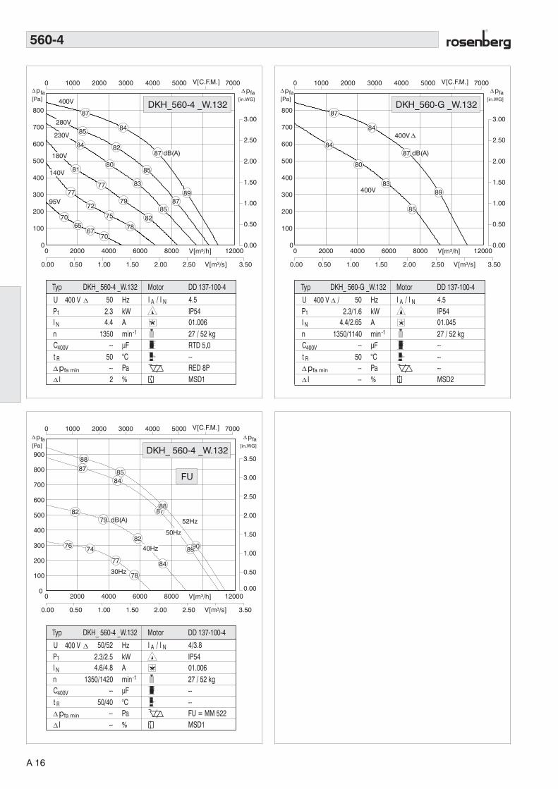
27 / 52 kg
IP5401.006
RTD 5,0--RED 8PMSD1
P1
N
U
InCt
400 V
min-1AkWHz 4.5
uF°CPa%
400V
R
2.34.4
50
--50--2
I A / I N
Typ
1350
Ipfa min
Motor DD 137-100-4DKH_ 560-4 _W.132
0 2000 4000 6000 8000 V[m³/h] 12000
0.00 0.50 1.00 1.50 2.00 2.50 V[m³/s] 3.50
0 1000 2000 3000 4000 5000 V[C.F.M.] 7000
0
100
200
300
400
500
600
700
800
0.00
0.50
1.00
1.50
2.00
2.50
3.00
95V
p[Pa]
fa[in.WG]
pfa
DKH_560-4 _W.132400V
87
85
84
81
77
70
84
82
80
77
72
65
85
83
79
75
67
8987
8582
7870
230V
180V
140V
280V
87 dB(A)
27 / 52 kg
IP5401.045
------MSD2
P1
N
U
InCt
400 V / Y
min-1AkWHz 4.5
uF°CPa%
400V
R
2.3/1.64.4/2.65
50
--50----
I A / I N
Typ
1350/1140
Ipfa min
Motor DD 137-100-4DKH_ 560-G _W.132
0 2000 4000 6000 8000 V[m³/h] 12000
0.00 0.50 1.00 1.50 2.00 2.50 V[m³/s] 3.50
0 1000 2000 3000 4000 5000 V[C.F.M.] 7000
0
100
200
300
400
500
600
700
800
0.00
0.50
1.00
1.50
2.00
2.50
3.00
p[Pa]
fa[in.WG]
pfa
DKH_560-G _W.132
400V
400V Y
87
84
84
80
8389
85
87 dB(A)
560-4
0.00
0.50
1.00
1.50
2.00
2.50
3.00
3.50
0
100
200
300
400
500
600
700
800
900
0 1000 2000 3000 4000 5000 V[C.F.M.] 7000
0 2000 4000 6000 8000 V[m³/h] 12000
0.00 0.50 1.00 1.50 2.00 2.50 V[m³/s] 3.50
52Hz
30Hz
8887
82
76
8584
79 dB(A)
74
82
77
89
84
78
90
50Hz
40Hz
27 / 52 kg
IP5401.006
----FU = MM 522MSD1
P1
N
U
InCt
400 V
min-1AkWHz 4/3.8
uF°CPa%
400V
R
2.3/2.54.6/4.8
50/52
--50/40
----
I A / I N
Typ
1350/1420
Ipfa min
Motor DD 137-100-4DKH_ 560-4 _W.132
p[Pa]
fa[in.WG]
pfa
DKH_ 560-4 _W.132
FU
8788
A 16

37.5 / 62 kg
IP5401.006
RTD 10--RED 8PMSD1 (7,5 kW)
P1
N
U
InCt
400 V
min-1AkWHz 5
uF°CPa%
400V
R
3.15.5
50
--40--
30
I A / I N
Typ
1410
Ipfa min
Motor DD 165-95-4DKH_ 560-4 _W.174
0
100
200
300
400
500
600
700
800
0.00
0.50
1.00
1.50
2.00
2.50
3.00
0 1000 2000 3000 4000 5000 6000 V[C.F.M.] 8000
0 2000 4000 6000 8000 10000 V[m³/h] 14000
0.00 0.50 1.00 1.50 2.00 2.50 3.00 V[m³/s] 4.00
88
87
86
84
79
72
85
84
82
79
73
66
88 dB(A)
86
85
81
75
68
9291
89
86
8073
95V
p[Pa]
fa[in.WG]
pfa
DKH_560-4 _W.174400V
230V
180V
140V
280V
37.5 / 62 kg
IP5401.045
------MSD2 (7,5 kW)
P1
N
U
InCt
400 V / Y
min-1AkWHz 5
uF°CPa%
400V
R
3.1/2.45.5/4.0
50
--40----
I A / I N
Typ
1410/1225
Ipfa min
Motor DD 165-95-4DKH_ 560-G _W.174
0
100
200
300
400
500
600
700
800
0.00
0.50
1.00
1.50
2.00
2.50
3.00
0 1000 2000 3000 4000 5000 6000 V[C.F.M.] 8000
0 2000 4000 6000 8000 10000 V[m³/h] 14000
0.00 0.50 1.00 1.50 2.00 2.50 3.00 V[m³/s] 4.00
p[Pa]
fa[in.WG]
pfa
DKH_560-G _W.174
400V
400V Y
88
86
85
8288 dB(A)
85
92
89
0
250
500
750
1000
0.00
0.50
1.00
1.50
2.00
2.50
3.00
3.50
4.00
0 2000 4000 6000 8000 10000 12000 V[m³/h] 16000
0.00 0.50 1.00 1.50 2.00 2.50 3.00 3.50 V[m³/s] 4.50
0 1000 2000 3000 4000 5000 6000 7000V[C.F.M.]9000
57Hz
30Hz
90
88
83
77
87 dB(A)
85
80
74
90
88
83
77
94
92
87
81
50Hz
40Hz
37.5 / 62 kg
IP5401.006
----FU = MM 540MSD1 (7,5 kW)
P1
N
U
InCt
400 V
min-1AkWHz 5/4.5
uF°CPa%
400V
R
3.1/4.35.5/7.2
50/57
--70/40
----
I A / I N
Typ
1410/1560
Ipfa min
Motor DD 165-95-4DKH_ 560-4 _W.174
p[Pa]
fa[in.WG]
pfa
DKH_ 560-4 _W.174
FU
560-4
A 17

0 1000 2000 3000 4000 5000 6000 7000 V[m³/h] 9000
0.00 0.50 1.00 1.50 V[m³/s] 2.50
0 500 1000 1500 2000 2500 3000 3500 4000 4500 V[C.F.M.]
0
50
100
150
200
250
300
400
0.00
0.20
0.40
0.60
0.80
1.00
1.20
1.60
400V
95V
78
75
73
70
66
59
76
73
71
67
64
56
77
74
72
68
63
51
7976
7368
58
280V230V
180V140V
81 dB(A)
19 / 44 kg
IP5401.006
RTD 2.5--RED 8PMSD1
P1
N
U
InCt
400 V
min-1AkWHz 2.9
uF°CPa%
400V
R
0.871.9
50
--50----
I A / I N
Typ
870
p[Pa]
fa[in.WG]
pfa
Ipfa min
Motor DD 137-50-6DKH_ 560-6 _W.174
DKH_ 560-6 _W.174
0 1000 2000 3000 4000 5000 6000 7000 V[m³/h] 9000
0.00 0.50 1.00 1.50 V[m³/s] 2.50
0 500 1000 1500 2000 2500 3000 3500 4000 4500 V[C.F.M.]
0
50
100
150
200
250
300
400
0.00
0.20
0.40
0.60
0.80
1.00
1.20
1.60
19 / 44 kg
IP5401.045
------MSD2
P1
N
U
InCt
400 V / Y
min-1AkWHz 2.9
uF°CPa%
400V
R
0.87/0.531.9/0.95
50
--50----
I A / I N
DKH._ 560-H W.174Typ
870/680
p[Pa]
fa[in.WG]
pfa
Ipfa min
400V
400V Y
Motor DD 137-50-6
DKH_ 560-H _W.17478
73
76
71
77
72
76
81 dB(A)
16 / 41.5 kg
IP5401.006
RTD 1.2--RED 8PMSD1
P1
N
U
InCt
400 V
min-1AkWHz 2.0
uF°CPa%
400V
R
0.41.0
50
--50----
I A / I N
Typ
620
p[Pa]
fa
[in.WG]
pfa
Ipfa min
0 1000 2000 3000 4000 5000 V[m³/h] 7000
0.00 0.20 0.40 0.60 0.80 1.00 1.20 1.40 1.60 V[m³/s] 2.00
0 500 1000 1500 2000 2500 3000 V[C.F.M.] 4000
0
50
100
150
250
0.00
0.10
0.20
0.30
0.40
0.50
0.60
0.70
0.80
0.90400V
95V
70
68
66 dB(A)
62
56
48
68
64
61
57
52
69
65
63
58
52
73
6866
6256
48
280V
230V
180V
140V
Motor DD 137-35-8DKH_ 560-8 _W.174
DKH_ 560-8 _W.174
560-6 + 8
16 / 41.5 kg
IP5401.045
------MSD2
P1
N
U
InCt
400 V / Y
min-1AkWHz 2
uF°CPa%
400V
R
0.4/0.211.0/0.42
50
--50----
I A / I N
Typ
620/460
Ipfa min
p[Pa]
fa
[in.WG]
pfa
400V
400V Y
0 1000 2000 3000 4000 5000 V[m³/h] 7000
0.00 0.20 0.40 0.60 0.80 1.00 1.20 1.40 1.60 V[m³/s] 2.00
0 500 1000 1500 2000 2500 3000 V[C.F.M.] 4000
0
50
100
150
250
0.00
0.10
0.20
0.30
0.40
0.50
0.60
0.70
0.80
0.90415V
Motor DD 137-35-8DKH_ 560-M _W.174
DKH_ 560-M _W.174
70
66 dB(A)
68
61
69
63 73
66
A 18
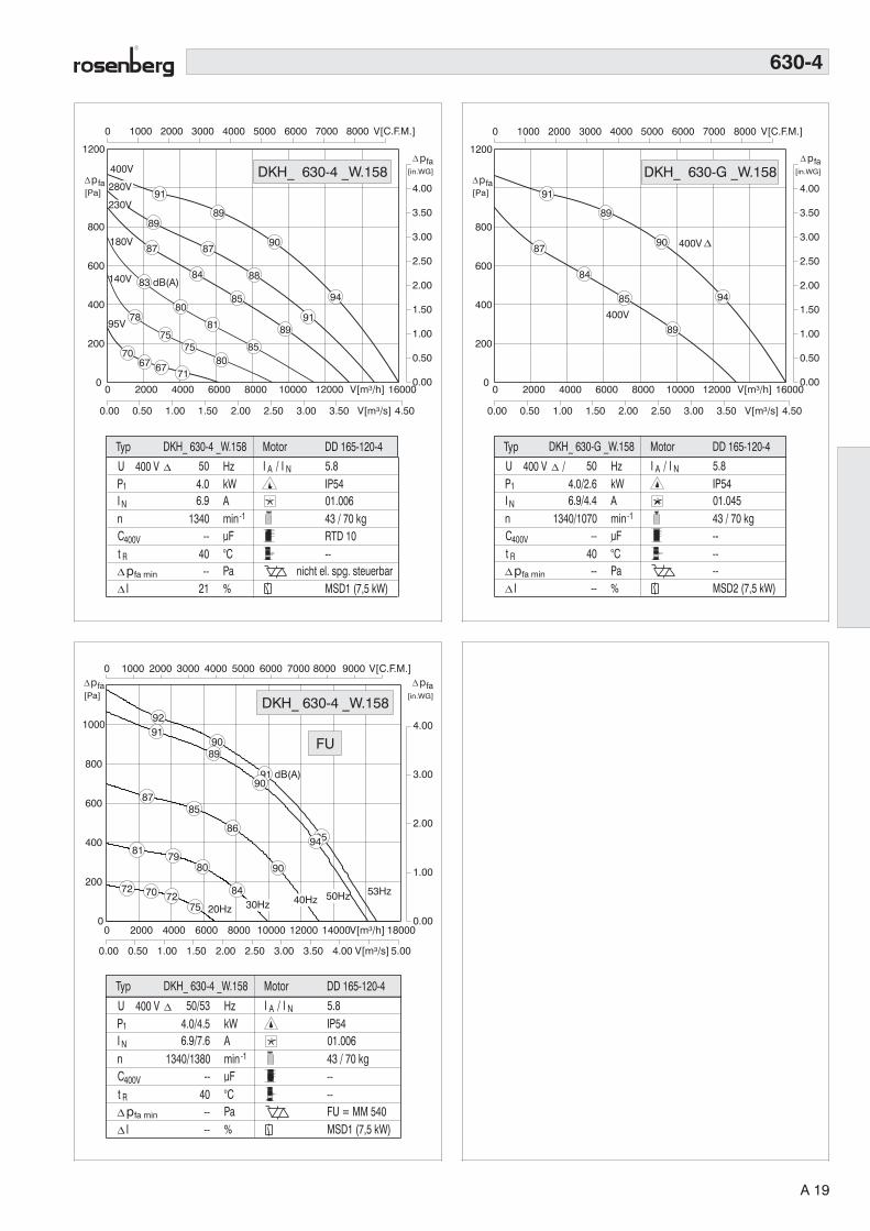
43 / 70 kg
IP5401.006
RTD 10--
nicht el. spg. steuerbarMSD1 (7,5 kW)
P1
N
U
InCt
400 V
min-1AkWHz 5.8
uF°CPa%
400V
R
4.06.9
50
--40--
21
I A / I N
Typ
1340
p[Pa]
fa[in.WG]
pfa
Ipfa min
0 2000 4000 6000 8000 10000 12000 V[m³/h] 16000
0.00 0.50 1.00 1.50 2.00 2.50 3.00 3.50 V[m³/s] 4.50
0 1000 2000 3000 4000 5000 6000 7000 8000 V[C.F.M.]
0
200
400
600
800
1200
0.00
0.50
1.00
1.50
2.00
2.50
3.00
3.50
4.00
400V
Motor DD 165-120-4DKH_ 630-4 _W.158
DKH_ 630-4 _W.15891
8989
87
84
80
75
90
88
85
81
75
67
94
9189
8580
95V
87
78
7067
180V
140V
71
83 dB(A)
230V
280V
43 / 70 kg
IP5401.045
------MSD2 (7,5 kW)
P1
N
U
InCt
400 V / Y
min-1AkWHz 5.8
uF°CPa%
400V
R
4.0/2.66.9/4.4
50
--40----
I A / I N
Typ
1340/1070
Ipfa min
p[Pa]
fa[in.WG]
pfa
0 2000 4000 6000 8000 10000 12000 V[m³/h] 16000
0.00 0.50 1.00 1.50 2.00 2.50 3.00 3.50 V[m³/s] 4.50
0 1000 2000 3000 4000 5000 6000 7000 8000 V[C.F.M.]
0
200
400
600
800
1200
0.00
0.50
1.00
1.50
2.00
2.50
3.00
3.50
4.00
400V
400V Y
Motor DD 165-120-4DKH_ 630-G _W.158
DKH_ 630-G _W.15891
89
84
90
85 94
89
87
0.00
1.00
2.00
3.00
4.00
0
200
400
600
800
1000
0 2000 4000 6000 8000 10000 12000 14000V[m³/h] 18000
0.00 0.50 1.00 1.50 2.00 2.50 3.00 3.50 4.00 V[m³/s] 5.00
0 1000 2000 3000 4000 5000 6000 7000 8000 9000 V[C.F.M.]
53Hz
20Hz
9291
87
81
72
9089
85
79
70
91 dB(A)90
86
80
72
9594
90
84
7550Hz40Hz30Hz
43 / 70 kg
IP5401.006
----FU = MM 540MSD1 (7,5 kW)
P1
N
U
InCt
400 V
min-1AkWHz 5.8
uF°CPa%
400V
R
4.0/4.56.9/7.6
50/53
--40----
I A / I N
Typ
1340/1380
Ipfa min
Motor DD 165-120-4DKH_ 630-4 _W.158
p[Pa]
fa[in.WG]
pfa
DKH_ 630-4 _W.158
FU
630-4
A 19

0 2000 4000 6000 8000 10000 V[m³/h] 14000
0.00 0.50 1.00 1.50 2.00 2.50 V[m³/s] 3.50
0 1000 2000 3000 4000 5000 6000 V[C.F.M.] 8000
0
50
100
150
200
250
300
350
400
500
0.00
0.20
0.40
0.60
0.80
1.00
1.20
1.40
1.60
2.00
400V
82
80
79
76
71
63
80
78
76
72
68
61
81
79
77
73
68
61
8280
7672
65 280V
230V180V
140V95V
84 dB(A)
28 / 57 kg
IP5401.006
RTD 3,8--RED 8PMSD1
P1
N
U
InCt
400 V
min-1AkWHz 3.2
uF°CPa%
400V
R
1.43.0
50
--65----
I A / I N
Typ
880
p[Pa]
fa[in.WG]
pfa
Ipfa min
Motor DD 137-100-6DKH_ 630-6 _W.195
DKH_ 630-6 _W.195
0 2000 4000 6000 8000 10000 V[m³/h] 14000
0.00 0.50 1.00 1.50 2.00 2.50 V[m³/s] 3.50
0 1000 2000 3000 4000 5000 6000 V[C.F.M.] 8000
0
50
100
150
200
250
300
350
400
500
0.00
0.20
0.40
0.60
0.80
1.00
1.20
1.40
1.60
2.00
28 / 57 kg
IP5401.045
------MSD2
P1
N
U
InCt
400 V / Y
min-1AkWHz 3.2
uF°CPa%
400V
R
1.4/0.93.0/1.6
50
--65----
I A / I N
Typ
880/710
p[Pa]
fa[in.WG]
pfa
Ipfa min
82
79
80
76
81
77
80
84 dB(A)
400V
400V Y
Motor DD 137-100-6DKH_ 630-H _W.195
DKH_ 630-H _W.195
0
0 1000 2000 3000 4000 5000 6000 V[C.F.M.] 8000
0 2000 4000 6000 8000 10000 V[m³/h] 14000
0.00 0.50 1.00 1.50 2.00 2.50 3.00 V[m³/s] 4.00
0.00
0.40
0.80
1.20
1.60
2.00
0
200
300
400
500
10030Hz
83
82
78
72
8180
76
70
8281
77
71
8584
80
55Hz
50Hz
40Hz
74 dB(A)
28 / 57 kg
IP5401.006
----FU = MM 515MSD1
P1
N
U
InCt
400 V
min-1AkWHz 3.2/2.5
uF°CPa%
400V
R
1.40/1.753.0/3.6
50/55
--65/40
----
I A / I N
Typ
860/890
Ipfa min
Motor DD 137-100-6DKH_ 630-6 _W.195
p[Pa]
fa[in.WG]
pfa
DKH_ 630-6 _W.195
FU
630-6
A 20
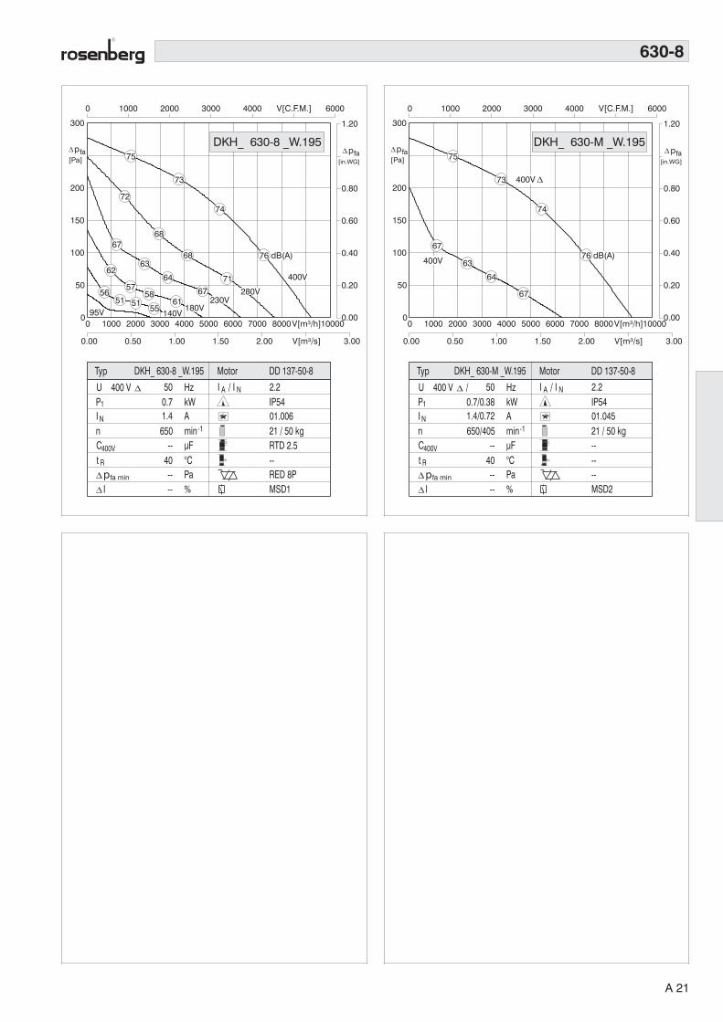
0 1000 2000 3000 4000 5000 6000 7000 8000V[m³/h]10000
0.00 0.50 1.00 1.50 2.00 V[m³/s] 3.00
0 1000 2000 3000 4000 V[C.F.M.] 6000
0
50
100
150
200
300
0.00
0.20
0.40
0.60
0.80
1.20
95V
75
72
67
62
56
73
68
63
57
51
74
68
64
5851
7167
6155
400V
280V230V
180V140V
76 dB(A)
21 / 50 kg
IP5401.006
RTD 2.5--RED 8PMSD1
P1
N
U
InCt
400 V
min-1AkWHz 2.2
uF°CPa%
400V
R
0.71.4
50
--40----
I A / I N
Typ
650
p[Pa]
fa[in.WG]
pfa
Ipfa min
Motor DD 137-50-8DKH_ 630-8 _W.195
DKH_ 630-8 _W.195
0 1000 2000 3000 4000 5000 6000 7000 8000V[m³/h]10000
0.00 0.50 1.00 1.50 2.00 V[m³/s] 3.00
0 1000 2000 3000 4000 V[C.F.M.] 6000
0
50
100
150
200
300
0.00
0.20
0.40
0.60
0.80
1.20
21 / 50 kg
IP5401.045
------MSD2
P1
N
U
InCt
400 V / Y
min-1AkWHz 2.2
uF°CPa%
400V
R
0.7/0.381.4/0.72
50
--40----
I A / I N
Typ
650/405
p[Pa]
fa[in.WG]
pfa
Ipfa min
400V
400V Y
Motor DD 137-50-8DKH_ 630-M _W.195
DKH_ 630-M _W.19575
67
73
63
74
64
67
76 dB(A)
630-8
A 21

0 2000 4000 6000 8000 10000 12000 14000 V[m³/h]18000
0.00 0.50 1.00 1.50 2.00 2.50 3.00 3.50 4.00V[m³/s] 5.00
0 2000 4000 6000 8000 V[C.F.M.]
0
100
200
300
400
500
700
0.00
0.50
1.00
1.50
2.50
95V
400V
280V
230V
180V
140V
40 / 88 kg
IP5401.006
RTD 7--RED 8PMSD1
P1
N
U
InCt
400 V
min-1AkWHz 3.6
uF°CPa%
400V
R
2.54.8
50
--45--
10
I A / I N
DD 165-95-6Typ Motor
890
p[Pa]
fa
[in.WG]
pfa
Ipfa min
86
84
82
80
73
66
83
81
77
73
67
85
82
79
74
68
60
88 dB(A)
8582
7771
DKH_ 710-6 _W.219
DKH_ 710-6 _W.219
0 2000 4000 6000 8000 10000 12000 14000 V[m³/h]18000
0.00 0.50 1.00 1.50 2.00 2.50 3.00 3.50 4.00V[m³/s] 5.00
0 2000 4000 6000 8000 V[C.F.M.]
0
100
200
300
400
500
700
0.00
0.50
1.00
1.50
2.50
IP5401.045
------MSD2
P1
N
U
InCt
400 V / Y
min-1AkWHz 3.6
uF°CPa%
400V
R
2.5/1.54.8/2.9
50
--45----
I A / I N
Typ
890/670
p[Pa]
fa
[in.WG]
pfa
Ipfa min
400V
400V Y
40 / 88 kg
DD 165-95-6MotorDKH_ 710-H _W.219
DKH_ 710-H _W.219
86
82
83
77
85
79 88 dB(A)
82
710-6
0.00
0.50
1.00
1.50
2.00
2.50
3.00
0
100
200
300
400
500
600
700
0 2500 5000 7500 10000 V[C.F.M.]
0 2500 5000 7500 10000 12500 15000 17500 V[m³/h] 22500
0.00 1.00 2.00 3.00 4.00 5.00 V[m³/s]
57Hz
89
87
82
76
87
80
74
88
86
81
76
9088
83
78
50Hz
40Hz
30Hz
84 dB(A)
43 / 91 kg
IP5401.006
----FU = MM 540MSD1
P1
N
U
InCt
400 V
min-1AkWHz 3.6/3.1
uF°CPa%
400V
R
2.6/3.555.2/6.6
50/57
--70/40
----
I A / I N
Typ
920/990
Ipfa min
Motor DD 165-120-6DKH_ 710-6 _W.219
p[Pa]
fa [in.WG]
pfa
DKH_ 710-6 _W.219
FU
A 22
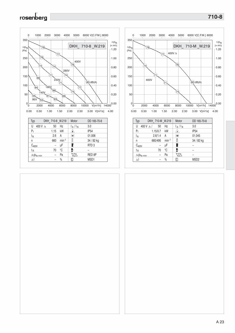
0 2000 4000 6000 8000 10000 V[m³/h] 14000
0.00 0.50 1.00 1.50 2.00 2.50 3.00 V[m³/s] 4.00
0 1000 2000 3000 4000 5000 6000 V[C.F.M.] 8000
0
50
100
150
200
250
350
0.00
0.20
0.40
0.60
0.80
1.00
1.20
400V
95V
IP5401.006
RTD 3--RED 8PMSD1
P1
N
U
InCt
400 V
min-1AkWHz 3.0
uF°CPa%
400V
R
1.152.6
50
--70----
I A / I N
Typ
660
p[Pa]
fa[in.WG]
pfa
Ipfa min
78
76
74
69
64
55
77
74
71
78
71
66
61
53
77
74
6963
230V
180V
280V
140V
74
80 dB(A)
34 / 82 kg
DD 165-70-8MotorDKH_ 710-8 _W.219
DKH_ 710-8 _W.219
0 2000 4000 6000 8000 10000 V[m³/h] 14000
0.00 0.50 1.00 1.50 2.00 2.50 3.00 V[m³/s] 4.00
0 1000 2000 3000 4000 5000 6000 V[C.F.M.] 8000
0
50
100
150
200
250
350
0.00
0.20
0.40
0.60
0.80
1.00
1.20
IP5401.045
------MSD2
P1
N
U
InCt
400 V / Y
min-1AkWHz 3.0
uF°CPa%
400V
R
1.15/0.72.6/1.4
50
--70----
I A / I N
Typ
660/495
p[Pa]
fa[in.WG]
pfa
Ipfa min
400V
400V Y
34 / 82 kg
DD 165-70-8MotorDKH_ 710-M _W.219
DKH_ 710-M _W.21978
74
77
71
78
71
74
80 dB(A)
710-8
A 23
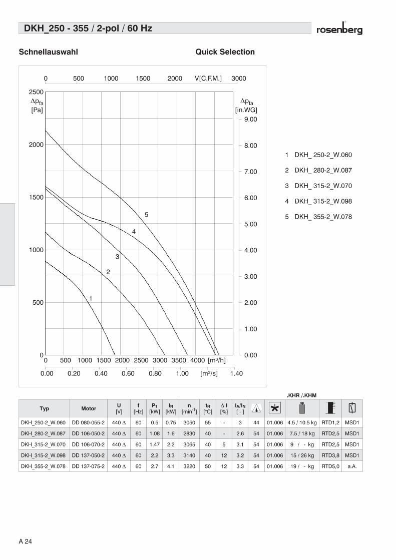
DKH_250 - 355 / 2-pol / 60 Hz
0 500 1000 1500 2000 2500 3000 3500 4000 [m³/h]
0.00 0.20 0.40 0.60 0.80 1.00 [m³/s] 1.40
0 500 1000 1500 2000 V[C.F.M.] 3000
0
500
1000
1500
2000
2500
0.00
1.00
2.00
3.00
4.00
5.00
6.00
7.00
8.00
9.00
1
2
3
4
5
[Pa]∆pfa
[in.WG]∆pfa
Schnellauswahl Quick Selection
1 DKH_ 250-2_W.060
2 DKH_ 280-2_W.087
3 DKH_ 315-2_W.070
4 DKH_ 315-2_W.098
5 DKH_ 355-2_W.078
Typ Motor U[V]
f[Hz]
P1[kW]
IN[kW]
n[min-1]
tR[°C]
∆ I[%]
IA/IN[ - ]
DKH_250-2_W.060 DD 080-055-2 440 ∆ 60 0.5 0.75 3050 55 - 3 44 01.006 4.5 / 10.5 kg RTD1,2 MSD1
DKH_280-2_W.087 DD 106-050-2 440 ∆ 60 1.08 1.6 2830 40 - 2.6 54 01.006 7.5 / 18 kg RTD2,5 MSD1
DKH_315-2_W.070 DD 106-070-2 440 ∆ 60 1.47 2.2 3065 40 5 3.1 54 01.006 9 / - kg RTD2,5 MSD1
DKH_315-2_W.098 DD 137-050-2 440 ∆ 60 2.2 3.3 3140 40 12 3.2 54 01.006 15 / 26 kg RTD3,8 MSD1
DKH_355-2_W.078 DD 137-075-2 440 ∆ 60 2.7 4.1 3220 50 12 3.3 54 01.006 19 / - kg RTD5,0 a.A.
.KHR /.KHM
A 24

DKH_315 - 630 / 4-pol + 6-pol / 60 Hz
0 2000 4000 6000 8000 10000 12000 14000 [m³/h]
0.00 0.50 1.00 1.50 2.00 2.50 3.00 [m³/s] 4.00
0 1000 2000 3000 4000 5000 6000 7000 [C.F.M.]9000
0
100
200
300
400
500
600
700
800
900
[Pa]∆pfa
[in.WG]∆pfa
0.00
0.50
1.00
1.50
2.00
2.50
3.00
3.50
1
2
3
4
5
6 78
9
1 DKH_ 315-4_W.098
2 DKH_ 355-4_W.110
3 DKH_ 400-4_W.123
4 DKH_ 450-4_W.138
5 DKH_ 500-4_W.155
6 DKH_ 450-6_W.138
7 DKH_ 500-6_W.155
8 DKH_ 560-6_W.174
9 DKH_ 630-6_W.195
Typ Motor U[V]
f[Hz]
P1[kW]
IN[kW]
n[min-1]
tR[°C]
∆ I[%]
IA/IN[ - ]
DKH_315-4_W.098 DD 080-042-4 440 ∆ 60 0.39 0.50 1610 70 - 2.5 44 01.006 4.5 / 10.5 kg RTD1,2 MSD1
DKH_355-4_W.110 DD 080-055-4 440 ∆ 60 0.49 0.80 1560 50 4 2.9 44 01.006 7.5 / 18 kg RTD1,2 MSD1
DKH_400-4_W.123 DD 106-070-4 440 ∆ 60 0.79 1.5 1475 65 - 2.6 54 01.006 9.0 / 20 kg RTD2,5 MSD1
DKH_450-4_W.138 DD 137-050-4 440 ∆ 60 1.6 2.7 1600 60 8 3.5 54 01.006 15 / 26 kg RTD3,8 MSD1
DKH_500-4_W.155 DD 137-100-4 440 ∆ 60 2.8 4.5 1610 50 13 4.4 54 01.006 24 / 41.5 kg RTD5,0 a.A.
DKH_450-6_W.138 DD 106-050-6 440 ∆ 60 0.67 0.9 1060 60 8 3.2 54 01.006 9.5 / 28 kg RTD1,2 MSD1
DKH_500-6_W.155 DD 137-050-6 440 ∆ 60 0.87 1.7 1030 70 - 3.6 54 01.006 19 / 36 kg RTD2,5 MSD1
DKH_560-6_W.174 DD 137-100-6 440 ∆ 60 1.4 3.0 1070 70 - 3.2 54 01.006 26 / 51 kg RTD3,0 MSD1
DKH_630-6_W.195 DD 165-095-6 440 ∆ 60 2.6 4.5 1090 50 13 3.0 54 01.006 40 / 67 kg RTD5,0 MSD1
Schnellauswahl Quick Selection
.KHR /.KHM
A 25
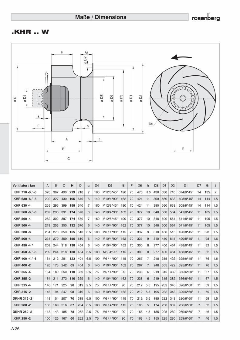
Maße / Dimensions
.KHR .. W
øD
E
øD
4
øD
øD
6
øD
3
øD
1
øD
2A
H G
øD
7
t
hF
a
B E
C
D5
Ventilator / fan A B C H D a D4 D5 E F D6 h DE D3 D2 D1 D7 G t
.KHR 710 -6 / -8 328 367 490 219 718 7 160 M12/8*45° 190 70 476 12.5 438 630 710 674/8*45° 14 135 2
.KHR 630 -6 / -8 292 327 430 195 640 6 140 M10/4*90° 162 70 424 11 390 560 638 608/8*45° 14 114 1.5
.KHR 630 -4 255 296 399 158 640 7 160 M12/8*45° 190 70 424 11 390 560 638 608/8*45° 14 114 1.5
.KHR 560 -6 / -8 262 296 391 174 570 6 140 M10/4*90° 162 70 377 10 348 500 564 541/8*45° 11 105 1.5
.KHR 560 -4 262 302 397 174 570 7 160 M12/8*45° 190 70 377 10 348 500 564 541/8*45° 11 105 1.5
.KHR 560 -4 219 253 350 132 570 6 140 M10/4*90° 162 70 377 10 348 500 564 541/8*45° 11 105 1.5
.KHR 500 -6 234 270 359 155 510 6.5 100 M6 / 4*90° 115 70 337 9 310 450 515 490/8*45° 11 98 1.5
.KHR 500 -4 234 270 359 155 510 6 140 M10/4*90° 162 70 337 9 310 450 515 490/8*45° 11 98 1.5
.KHR 450 -4 * 209 244 318 138 454 6 140 M10/4*90° 162 70 300 8 277 400 464 438/8*45° 11 82 1.5
.KHR 450 -4 / -6 209 244 318 138 454 6.5 100 M6/ 4*90° 115 70 300 8 277 400 464 438/8*45° 11 82 1.5
.KHR 400 -4 / -6 184 212 281 123 404 6.5 100 M6 / 4*90° 115 70 267 7 248 355 422 395/8*45° 11 76 1.5
.KHR 400 -2 126 173 242 65 404 6 140 M10/4*90° 162 70 267 7 248 355 422 395/8*45° 11 76 1.5
.KHR 355 -4 164 189 250 110 359 2.5 75 M6 / 4*90° 90 70 238 6 219 315 382 356/6*60° 11 67 1.5
.KHR 355 -2 164 211 272 110 359 6 140 M10/4*90° 162 70 238 6 219 315 382 356/6*60° 11 67 1.5
.KHR 315 -4 146 171 225 98 319 2.5 75 M6 / 4*90° 90 70 212 5.5 195 282 348 320/6*60° 11 59 1.5
.KHR 315 -2 146 194 247 98 319 6 140 M10/4*90° 162 70 212 5.5 195 282 348 320/6*60° 11 59 1.5
DKHR 315 -2 118 154 207 70 319 6.5 100 M6 / 4*90° 115 70 212 5.5 195 282 348 320/6*60° 11 59 1.5
.KHR 280 -2 133 169 216 87 284 6.5 100 M6 / 4*90° 115 70 188 5 174 250 307 286/6*60° 7 52 1.5
DKHR 250 -2 118 143 185 78 252 2.5 75 M6 / 4*90° 90 70 168 4.5 155 225 280 259/6*60° 7 46 1.5
.KHR 250 -2 100 125 167 60 252 2.5 75 M6 / 4*90° 90 70 168 4.5 155 225 280 259/6*60° 7 46 1.5
A 26
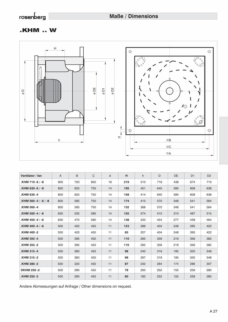
.KHM .. W
C
B
A
øD
øD
1
øD
2F
a
h
H
øD
E
d
Maße / Dimensions
Ventilator / fan A B C d H h D DE D1 D2
.KHM 710 -6 / -8 900 720 850 18 219 510 718 438 674 710
.KHM 630 -6 / -8 800 625 750 14 195 451 640 390 608 638
.KHM 630 -4 800 625 750 14 158 414 640 390 608 638
.KHM 560 -4 / -6 / -8 800 585 750 14 174 410 570 348 541 564
.KHM 560 -4 800 585 750 14 132 368 570 348 541 564
.KHM 500 -4 / -6 630 535 580 14 155 374 510 310 487 515
.KHM 450 -4 / -6 630 470 580 14 138 333 454 277 438 464
.KHM 400 -4 / -6 500 420 450 11 123 296 404 248 395 422
.KHM 400 -2 500 420 450 11 65 257 404 248 395 422
.KHM 355 -4 500 395 450 11 110 265 359 219 356 382
.KHM 355 -2 500 395 450 11 110 292 359 219 356 382
.KHM 315 -4 500 360 450 11 98 240 319 195 320 348
.KHM 315 -2 500 360 450 11 98 267 319 195 320 348
.KHM 280 -2 500 320 450 11 87 232 284 174 286 307
DKHM 250 -2 500 290 450 11 78 200 252 155 259 280
.KHM 250 -2 500 290 450 11 60 182 252 155 259 280
Andere Abmessungen auf Anfrage / Other dimensions on request.
A 27
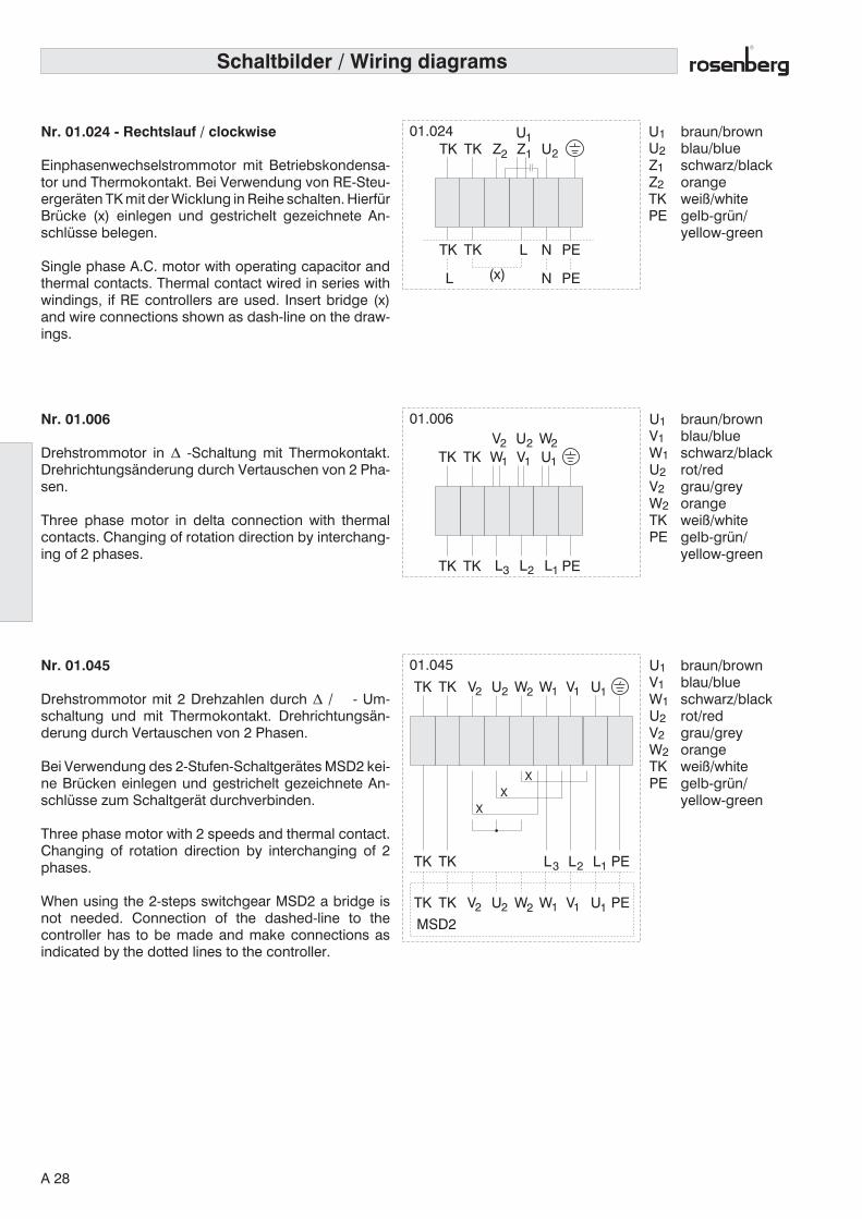
UVWTK
TK PE
TK
TK
V U W
L L L
111
2 2 2
3 2 1
01.006
ZU
UTKTK
L N
N PE(x)L
TKTK PE
Z 121
2
01.024
Nr. 01.006
Drehstrommotor in ∆ -Schaltung mit Thermokontakt.Drehrichtungsänderung durch Vertauschen von 2 Pha-sen.
Three phase motor in delta connection with thermalcontacts. Changing of rotation direction by interchang-ing of 2 phases.
Nr. 01.024 - Rechtslauf / clockwise
Einphasenwechselstrommotor mit Betriebskondensa-tor und Thermokontakt. Bei Verwendung von RE-Steu-ergeräten TK mit der Wicklung in Reihe schalten. HierfürBrücke (x) einlegen und gestrichelt gezeichnete An-schlüsse belegen.
Single phase A.C. motor with operating capacitor andthermal contacts. Thermal contact wired in series withwindings, if RE controllers are used. Insert bridge (x)and wire connections shown as dash-line on the draw-ings.
U1V1W1U2V2W2TKPE
braun/brownblau/blueschwarz/blackrot/redgrau/greyorangeweiß/whitegelb-grün/yellow-green
U1U2Z1Z2TKPE
braun/brownblau/blueschwarz/blackorangeweiß/whitegelb-grün/yellow-green
Nr. 01.045
Drehstrommotor mit 2 Drehzahlen durch ∆ / Y - Um-schaltung und mit Thermokontakt. Drehrichtungsän-derung durch Vertauschen von 2 Phasen.
Bei Verwendung des 2-Stufen-Schaltgerätes MSD2 kei-ne Brücken einlegen und gestrichelt gezeichnete An-schlüsse zum Schaltgerät durchverbinden.
Three phase motor with 2 speeds and thermal contact.Changing of rotation direction by interchanging of 2phases.
When using the 2-steps switchgear MSD2 a bridge isnot needed. Connection of the dashed-line to thecontroller has to be made and make connections asindicated by the dotted lines to the controller.
UW
UW
VU
VU
WV
W
LTKTK L L
V
TK
TK PE
PE
TK
TKMSD2
12
12
12
12
12
XX
XY
1
3 2 1
2
01.045
Schaltbilder / Wiring diagrams
U1V1W1U2V2W2TKPE
braun/brownblau/blueschwarz/blackrot/redgrau/greyorangeweiß/whitegelb-grün/yellow-green
A 28
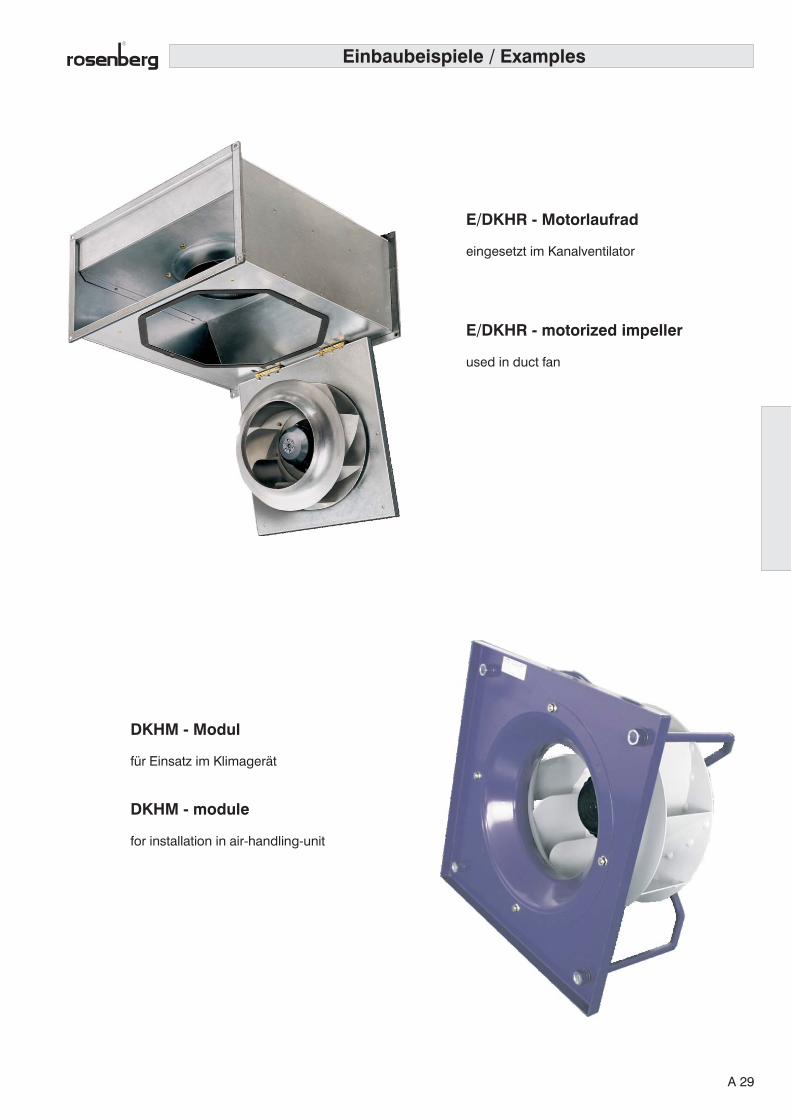
Einbaubeispiele / Examples
E/DKHR - Motorlaufrad
eingesetzt im Kanalventilator
E/DKHR - motorized impeller
used in duct fan
DKHM - Modul
für Einsatz im Klimagerät
DKHM - module
for installation in air-handling-unit
A 29

Rosenberg Radialventilatoren mit freilaufendem LaufradTypenreihe _KH_
Einseitig saugendes, rückwärtsgekrümmtes Hochleistungslaufrad aus seewasser-beständigem Aluminium auf spannungssteuerbaren Aussenläufermotor aufgebaut;incl. strömungsoptimierter Einströmdüse aus verzinktem Stahlblech. Lieferbar alsMotorlüfterrad (_KHR) oder als komplettes Ventilatoreinbaumodul (_KHM).
Einheit entsprechend Gütestufe G 2.5 nach DIN/ISO 1940 auf 2 Ebenen ausge-wuchtet.
Antriebsmotor geschlossen, Schutzart IP54 mit Feuchtschutzimprägnierung undmit in der Wicklung eingebauten und ausgeführten Thermokontakten. Wartungs-freie Kugellager beidseitig geschlossen mit Langzeitschmierung. Elektrischer An-schluß durch außenliegenden Anschlußkasten in Schutzart IP54.
DokumentationHerstellererklärung und Betriebsanleitung entsprechend der MaschinenrichtlinieEWG, CE Kennzeichnung entsprechend der EMV Richtlinie 89/336/EWG und derNiederspannungsrichtlinie 98/37/EWG.
Radialventilator wie vor beschrieben:
Volumenstrom V m3/ hDruckerhöhung pt PaSpannung U VFrequenz f HzLeistungsaufnahme P1 kWStromaufnahme I ADrehzahl n min-1
Schalleistungspegel LWA dB(A)Fördermitteltemperatur tR °CFlansch mmAbmessungen L x B x H mmMasse m kg
Fabrikat : Rosenberg Type
Projekt :
Anlage : Seite:
Pos. Anzahl EinzelpreisBeschreibung
Ausschreibungstext
A 30
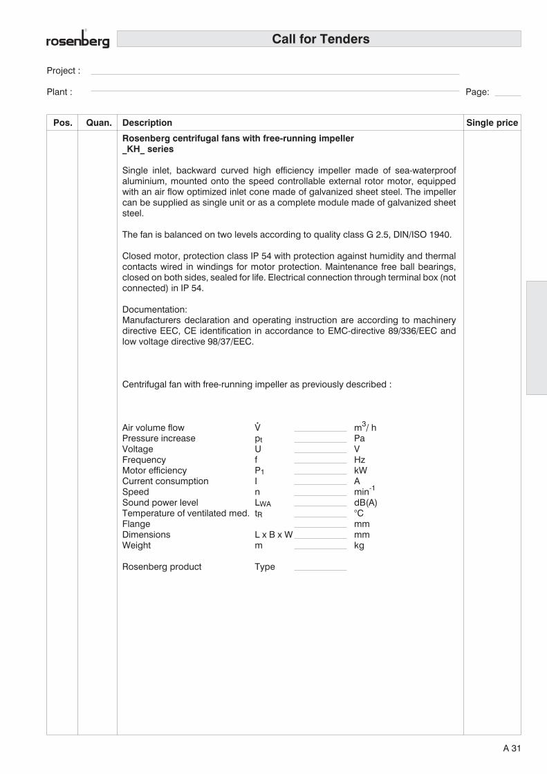
Call for Tenders
Rosenberg centrifugal fans with free-running impeller_KH_ series
Single inlet, backward curved high efficiency impeller made of sea-waterproofaluminium, mounted onto the speed controllable external rotor motor, equippedwith an air flow optimized inlet cone made of galvanized sheet steel. The impellercan be supplied as single unit or as a complete module made of galvanized sheetsteel.
The fan is balanced on two levels according to quality class G 2.5, DIN/ISO 1940.
Closed motor, protection class IP 54 with protection against humidity and thermalcontacts wired in windings for motor protection. Maintenance free ball bearings,closed on both sides, sealed for life. Electrical connection through terminal box (notconnected) in IP 54.
Documentation:Manufacturers declaration and operating instruction are according to machinerydirective EEC, CE identification in accordance to EMC-directive 89/336/EEC andlow voltage directive 98/37/EEC.
Centrifugal fan with free-running impeller as previously described :
Air volume flow V m3/ hPressure increase pt PaVoltage U VFrequency f HzMotor efficiency P1 kWCurrent consumption I ASpeed n min-1
Sound power level LWA dB(A)Temperature of ventilated med. tR °CFlange mmDimensions L x B x W mmWeight m kg
Rosenberg product Type
Project :
Plant : Page:
Pos. Quan. Single priceDescription
A 31

GKH_
Vorteile:
• kompakte, raumsparende Bauart
• Laufrad mit hoher Leistungsdichte
• hohe Wirtschaftlichkeit durch EC- Motorantrieb undwirkungsgradoptimiertes Laufrad
• in allen Einbaulagen montierbar
• wartungsfreundlich, da kein Keilriemenverschleiß und-abrieb
• hervorragende Drehzahlsteuerbarkeit
• gleichbleibend hoher Wirkungsgrad
• unabhängig von der Netzfrequenz50/60 Hz Betrieb bei gleicher Leistung
Advantages:
• compact, space saving construction
• high power impeller
• economic due to high efficiency impellerand EC-drive
• installable in all positions
• easy to maintain due to no attrition
• excellent speed controlability
• constant high efficiency
• independant of 50/60 Hz power supplyfrequency
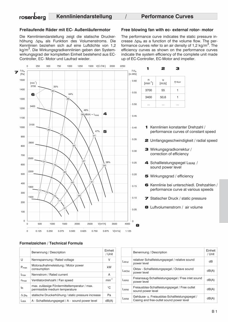
Kennliniendarstellung / Performance Curves
Freilaufende Räder mit EC- Außenläufermotor
Die Kennliniendarstellung zeigt die statische Drucker-höhung �pfa als Funktion des Volumenstroms. DieKennlinien beziehen sich auf eine Luftdichte von 1,2kg/m3. Die Wirkungsgradkennlinien geben den System-wirkungsgrad der kompletten Einheit bestehend aus EC-Controller, EC- Motor und Laufrad wieder.
Free blowing fan with ec- external rotor- motor
The performance curve indicates the static pressure in-crease �pfa as a function of the volume flow. The per-formance curves refer to an air density of 1,2 kg/m3. Theefficiency curves as shown on the performance curvesindicate the system efficiency of the complete unit madeup of EC-Controller, EC-Motor and impeller.
Formelzeichen / Technical Formula
Benennung / DescriptionEinheit/ Unit
U Nennspannung / Rated voltage V
PmaxMotoraufnahmeleistung / Motor powerconsumption
kW
Imax Nennstrom / Rated current A
nmax Ventilatordrehzahl / Fan speed min-1
tRmax. zulässige Fördermitteltemperatur / max.permissible medium temperature
°C
� pfa statische Druckerhöhung / static pressure increase Pa
LWA A - Schallleistungspegel / A - sound power level dB(A)
[Pa] [in.WG]
pfa� pfa�
0 250 500 750 1000 1250 1500 V[C.F.M.] 2000 2250
100
200
300
400
500
600
700
800
900
1000
1100
1200
1300
1400
1500
3700 35%
38%
44%
47%
48%
3400
3100
2800
2500
2200
1800
1500
[min ]-1
00
0 0.125 0.250 0.375 0.500 0.625 0.750 0.875 V[m³/s] 1.125
500 1000 1500 2000 2500 V[m³/h] 3500 40000
0.05
0.10
0.15
0.20
0.25
0.30
0.35
0.40
0.45
0.50
0.55
0.60
90
88
86
84
93
91
85
81
77
76
7577
8179
80
82
85
91
87
89 dB(A) = LWA8
n[min-1]
u[m/s]
� Korr
3700 55 1
3400 50,6 1
... ... ...
1 2 3
4
7
6
5
8
1 Kennlinien konstanter Drehzahl /performance curves of constant speed
2 Umfangsgeschwindigkeit / radial speed
3 Wirkungsgradkorrektur /correction of efficiency
4 Schallleistungspegel LWA8 /sound power level
5 Wirkungsgrad / efficiency
6 Kennlinie bei unterschiedl. Drehzahlen /performance curve at various speeds
7 Statischer Druck / static pressure
8 Luftvolumenstrom / air volume
Benennung / DescriptionEinheit/ Unit
LWrelrelativer Schallleistungspegel / relative soundpower level
dB
LWOktOktav - Schallleistungspegel / Octave soundpower level
dB(A)
LWA5Freiansaug-Schallleistungspegel / Free inlet soundpower level
dB(A)
LWA6Freiausblas-Schallleistungspegel / Free outletsound power level
dB(A)
LWA8Gehäuse- u. Freiausblas-Schallleistungspegel /Casing and free-outlet sound power level
dB(A)
B 1

Eigenschaften und Ausführung
Die Rosenberg Radialventilatoren mit freilaufendemRad der Baureihen GKHR bzw. GKHM bilden durch dieVerbindung eines elektronisch kommutierten Außen-läufermotor (EC- Motor) und neuentwickeltem Laufrad ei-ne sehr kompakte, lufttechnisch und konstruktiv optimaleVentilatoreinheit.
Die Kombination von elektronisch kommutierten Rosen-berg- Aussenläufermotor, flexibler Laufradfertigung undleistungsfähiger Blechverarbeitung bietet die MöglichkeitVentilatormodule zu fertigen, die einen größtmöglichenKundennutzen bieten und auf die konstruktiven Bedürf-nisse der Kundenanwendung optimal abgestimmt sind.
Abhängig von der Bauform (siehe Seite 6) sind die Ven-tilatoreinheiten lieferbar als :
• GKHR: Motorlaufrad ohne oder mit lose beige-fügter Einströmdüse
• GKHM: Ventilatoreinbaumodul
EC-MotorElektronisch kommutierte Motoren (EC- Motoren) sindGleichstrommotoren mit Nebenschlußcharakteristik. ImGegensatz zum herkömmlichen Gleichstrommotor mitmechanischer Kommutierung entfallen hier die ver-schleißbehafteten Elemente wie Kollektor und Kohle-bürsten. Sie werden durch eine wartungsfreie Elektronikim EC-Controller ersetzt. EC-Motoren zeichnen sich durcheinen sehr hohen Wirkungsgrad sowie optimales Steu-erungs- und Regelungsverhalten aus. Die Drehrichtungdes Motors kann elektronisch reversiert werden. Der Ein-satz von Elektronik ermöglicht zusätzlich die Imple-mentierung von Zusatzfunktionen.
Aufbau und WirkungsweiseDurch die Außenläuferausführung des EC-Motors undseine kompakte Bauart bei hoher Leistungsdichte, ist derMotor für den Einsatz in der Lüftungs- und Klimatechnikprädestiniert. Der EC- Motor verbindet die Wartungs-freiheit der Asynchronmaschine mit den regeltechnischenWirkungsgradvorteilen des Gleichstrommotors die sichim besonderen bei reduzierter Drehzahl ergeben.
• Energieersparnis durch den Wegfall der Schlupf- undeines Großteils der Kupferverluste.
• Weniger zusätzliche Wärmeentwicklung. Dadurchkann die erforderliche Kühlleistung der raumlufttech-nischen Anlage verringert werden.
• Durch die hohe Leistungsdichte des EC- Motors kanndie Motorbaugröße reduziert werden. Dadurch kön-nen Verluste durch die Motorversperrung bei direkt-getriebenen Ventilatoren verringert werden.
• Die maximale Drehzahl ist von der Netzfrequenzunabhängig.
• Erheblicher Wirkungsgradvorteil beim Betrieb desVentilators mit reduzierter Drehzahl.
• Die kompakte Ausführung des Außenläufermotorsbleibt erhalten.
Features and Construction
Rosenberg centrifugal fans of the ranges GKHR andGKHM with free running impeller are very compactunits. With regard to the air movement, the fans have anoptimum design. They combine an electronically commu-tated external rotor motor and a new designed impeller.
This combination together with flexible production ofimpellers and efficient sheet metal handling makes itpossible to manufacture fan modules for various appli-cations. Constructive demands of the customer can bemet.
The fan modules can be provided (as shown on page 6)as:
• GKHR: motorized impeller (mounted and bal-anced) with or without inlet cone (loose)
• GKHM: module for installation
EC motorElectronic commuted motors (EC motors) are DC motorswith shunt characteristics. Contrary to the conventionalDC motors with mechanical commutation, no wear andtear elements such as collectors and carbon brushes arerequired. They are substituted by maintenance-freeelectronic circuitry in the EC controller. EC motors arecharacterised by their high efficiency and optimal open-/closed-loop control. An electronic reversal of the motor’sdirection of rotation is possible. The utili- sation ofelectronic circuitry furthermore allows for the realisation ofadditional functions.
Design and operationDue to the external rotor design, the EC motor with itscompact design and high power density is particularypredestined for use in ventilation and air conditioning.TheEC-Motor combines the maintenance free asynchronousmachine with the efficiency control advantages of a directcurrent motor, especially at low speeds.
• Energy savings due to zero slippage and a large partof the copper losses.
• Less additional heat generation. Hereby the requiredcooling performance of the air handling unit can bereduced.
• The motor construction size can be reduced as aresult of the EC-Motors high performance. Herebyminimising the losses as a result of motor blockagewith direct driven fans.
• The maximum speed is independent of the powerfrequency.
• Major efficiency advantages during operation at lowspeeds.
• The construction of the external rotor motor remainscompact.
B 2
RotorAnstelle des Kurzschlußläufers tritt ein Rotor, der mitPermanetmagneten bestückt ist. Für die elektronischeKommutierung wird eine externe Elektronik benötigt, dersogenannte EC- Controller. Durch den EC- Controllerwerden die Wicklungsstränge des angeschlossenenMotors so bestromt, dass eine kontinuierliche und ge-räuscharme Drehbewegung des Motors erzeugt wird.
Aus diesem Grund kann der EC- Motor nicht direkt amNetz betrieben werden.
Der Betrieb von EC- Motoren erfordert stets den Ein-satz der dazugehörigen Kommutierungseinheit (EC-Controller).
StatorDer Stator des EC- Motors ist dreisträngig aufgebaut. DieWicklungsstränge werden durch sechs Transistoren indrei Halbbrücken bestromt. Der dreisträngige Statorauf-bau hat den Vorteil gegenüber ein- oder zweisträngigenLösungen, dass die Leistungsdichte wesentlich höher istund durch höhere Anlaufmomente auch antriebs-technische Aufgaben gelöst werden können. Zusätzlichergibt sich ein optimales Rundlauf- und Geräuschver-halten.
Ein weiterer Vorteil besteht in der sensorlosen Ausführungdes EC- Motors. Die Kommutierung durch den EC-Controller erfolgt ohne zusätzlichen Hall- Sensor- Einbauim Motor. Dadurch ergeben sich folgende Vorteile:
• Vereinfachter Motoraufbau• Reduzierung von Anschlußklemmen, dadurch ist eine
schnellere und sichere Inbetriebnahme der Ventila-toreinheiten gewährleistet.
• für den Motoranschluß wird nur noch ein Kabel be-nötigt
Hinweis zur EMV- RichtlinieRosenberg Radialventilatoren mit freilaufendem Rad undEC- Motor- Antrieb und die für den Betrieb notwendigeelektronische Kommutierungseinheit entsprechen in ihrerAusführung der EMV- Richtlinie EMV 89/336/EWG. In derBetriebsanleitung ist angegeben, welche Maßnahmenbauseits einzuhalten sind, damit die Bestimmungen derEMV- Richtlinie 89/336/EWG eingehalten werden. DieEinhaltung der EMV- Richtlinie 89/336/EWG bezieht sichnur dann auf dieses Produkt, wenn es direkt am Nie-derspannungsnetz angeschlossen ist. Wird es in eine Ge-samtanlage integriert, mit anderen z.B. regelungs-technischen Komponenten, oder entgegen den Vorschrif-ten der Bedienungsanleitung betrieben, so ist der Her-steller oder Betreiber der Gesamtanlage für die Einhaltungder EMV- Richtlinie 89/336/EWG verantwortlich.
RotorA rotor with permanent magnets replaces the short-circuitarmature. An external electronic commutating unit, theso-called EC-Controller, provides for the electroniccommutation. The EC-Controller provides the windingswith electrical current so that, the motor rotates con-tinuously and quietly.
This is the reason why the EC motor must not beoperated directly from the mains.
The operation of an EC motor always requires the useof a matching commutating unit (EC-controller).
StatorThe stator of the EC motor is a three core design. Thephase windings are energised by six transistors in threehalf-bridges. An optimal concentric running and noisebehaviour is thus achieved. The three core stator designhas an advantage over the one- or two-core version, sincethe power density is substantially higher and a higherstart-up torque will allow for the realisation of specific drivefunctions.
A further advantage is the sensorless construction of theEC-Motor. The commutation takes place without the extrainstallation of Hall- Sensors- in the motor. This providesthe following advantages:
• Simplifies the motor assembly• Reduces the number of contact terminals, hereby
allowing for a faster and safer installation andoperation of the ventilator.
• Only one cable is required to connect the motor tothe ec-controller.
Notes on EMC guidelinesThe Rosenberg EC-motor driven, free blowing centrifugalfans and the electronic commutation units construction isin accordance with the EMC Directive EMC 89/336/EEC.The operating manual provides for measures to be takenduring installation to ensure that the EMC Directive 89/336/EEC are met. The EMC Directive 89/336/EEC arerelevant to this product only when it is connected to amains supply. If it is installed into a system with forexample, other electronically controlled components, or itis not operated in accordance with the operating manual,then the manufacturer or the operator of the completesystem are responsible for meeting the requirements ofthe EMC Directive 89/336/EEC.
B 3

Elektrischer AnschlußDie Ventilatoren werden einbaufertig geliefert und sind miteinem leicht zugänglichen Motorklemmkasten ausge-stattet. Die elektrische Installation ist nach den geltendenBestimmungen, unter Beachtung der örtlichen Vorschrif-ten, durchzuführen. Jedem Motor liegt ein Anschlußbildbei, aus dem der richtige Anschluß des Motors ersichtlichist. Der Motoranschluß ist nur mit abgeschirmten Kabeldurchzuführen, und darf einer Gesamtlänge von 10 mnicht überschreiten. Grundsätzlich ist die Bedienungsan-leitung der elektronischen Kommutierungseinheit zubeachten.
ZubehörSämtliche Zubehörteile für den Ventilator und dieelektronische Kommutiereinheit müssen separat bestelltwerden. Die Beschreibung, technische Daten und Ab-messungen sind im Anhang dieses Kataloges mit an-gegeben.
DrehzahlsteuerungDie Drehzahlvorgabe erfolgt stufenlos durch Anschlußeines externen Potentiometers (Zubehör). Zur einfach-eren Inbetriebnahme steht am EC-Controllers ein in-ternes Potentiometer zur Verfügung (Betriebsanleitungbeachten).
Hinweis zur KennliniendarstellungDie im Katalog abgebildeten Kennlinien gelten nur für diezugeordnete Kommutierungseinheit. In den Kennlinienangegebene Wirkungsgrade und Leistungsaufnahmenbeziehen sich auf das komplette System einschließlichaller Verluste durch den Einbaumotor und der elektron-ischen Kommutierungseinheit.
FördermitteltemperaturDie Ventilatoren der Baureihe GKH_ sind zur Förderungvon Luft und sonstigen, nicht aggressiven Gasen oderDämpfen geeignet. Die maximale Fördermitteltemperaturbeträgt 40°C .
Electrical ConnectionThe fans are delivered ready to install and are suppliedwith an easily accessible terminal box. The electricalinstallation must be undertaken in accordance with validregulations and local laws. An electrical connectiondiagram is provided with each motor and indicates howto correctly connect the motor to the ec-controller.Themotor connection must only to be carried out with asheathed cable which itself should not exceed 10 m inlength. In principal, the instructions in the operatingmanual for the electronic commutating unit are to befollowed.
AccessoriesAll accessories including the electronic commutating unithave to be ordered separately. The description, technicaldetails and dimensions are included at the back of thiscatalogue.
Speed controlThe speed control offers continuously variable controlwhen connected to an external potentiometer (Access-ory). The EC-controller has an internal potentiometer tosimplify the initial operation of the fan (see operating man-ual).
Performance Curves - NoteThe performance curves shown in this catalogue are onlyvalid for the allocated commutation units. The efficienciesand power consumptions mentioned always relate to thecomplete system including all losses caused by the motorand the commutation unit.
Air TemperatureThe fans of the GKH range are suitable for air and othernon-aggressive gases or steams. The maximum temper-ature of the medium is 40°C.
B 4

GKH_ 280
[Pa] [in.WG]
pfa� pfa�
0 250 500 750 1000 1250 1500 V[C.F.M.] 2000 2250
100
200
300
400
500
600
700
800
900
1000
1100
1200
1300
1400
1500
3700 35%
38%
44%
47%
48%
3400
3100
2800
2500
2200
1800
1500
[min ]-1
00
0 0.125 0.250 0.375 0.500 0.625 0.750 0.875 V[m³/s] 1.125
500 1000 1500 2000 2500 V[m³/h] 3500 40000
0.05
0.10
0.15
0.20
0.25
0.30
0.35
0.40
0.45
0.50
0.55
0.60
90
88
86
84
93
91
85
81
77
76
7577
8179
80
82
85
91
87
89 dB(A) = LWA8
n[min-1]
u[m/s]
� Korr
3700 55 1
3400 50,6 1
3100 46,1 1
2800 41,6 1
2500 37,2 0,99
2200 32,7 0,98
1800 26,8 0,97
1500 22,3 0,96
LWA5 = LWA8 - 6 dBLWA6 = LWA8 - 3 dBLWokt Austritt= LWA8 - LWrelLWokt Eintritt = LWA5 - LWrel
LWoct outlet = LWA8 - LWrelLWoct inlet = LWA5 - LWrel
f[Hz]
LWrel
Eintritt-Seite /
inlet side[dB]
Austritt-Seite /
outlet side[dB]
63 -1 -4
125 -4 -6
250 -1 -2
500 -2 -3
1K -5 -5
2K -10 -7
4K -11 -13
8K -14 -14
Düsenbeiwert /Calibration factork10 = 55
Ventilatortyp
Fan type
Gewicht / weight [kg]
GKHR GKHM
EC-Controller
EC-Controller
Nenn-spannung [V]Rated voltage
Pmax
[kW]
Imax
EC - Controller[A]
nmax
[min-1]
GKH_ 280-CKW.087.5FA 7 17,5 T03 3 ~ 400 1,7 2,8 3700
Pmax = maximale Leistung / maximum powerImax = maximale Stromaufnahme EC- Controller / Max. input current EC- Controllernmax = maximale Ventilatordrehzahl / Max. fan revolutions per minute
B 5

GKH_ 315
[Pa] [in.WG]
pfa� pfa�
0 500 1000 1500 V[C.F.M.]25002000
2950
2600
2300
2000
1700
1450
1200
1000
[min ]-1
00
0 0.20 0.40 0.60 0.80 1.00 1.40V[m³/s]
500 1000 1500 2000 2500 3000 V[m³/h]3500 4000 5000
1100
1000
900
800
700
600
500
400
300
200
100
0
0.50
1.00
1.50
2.00
2.50
3.00
3.50
4.00
4.50
38%
67
68
71
79
76
75
74
75
6667
83
82
81
82
86
42%
91
88
47%
50%
87 dB(A) = LWA8
46%
86
87
Ventilatortyp
Fan type
Gewicht / weight [kg]
GKHR GKHM
EC-Controller
EC-Controller
Nenn-spannung [V]Rated voltage
Pmax
[kW]
Imax
EC - Controller[A]
nmax
[min-1]
GKH_ 315-CKW.098.5FA 7,3 18,5 T03 3 ~ 400 1,5 2,5 2950
Pmax = maximale Leistung / maximum powerImax = maximale Stromaufnahme EC- Controller / Max. input current EC- Controllernmax = maximale Ventilatordrehzahl / Max. fan revolutions per minute
n[min-1]
u[m/s]
� Korr
2950 49,3 1
2600 43,4 1
2300 38,4 1
2000 33,4 1
1700 28,4 0,99
1450 24,2 0,98
1200 20,0 0,97
1000 16,7 0,96
LWA5 = LWA8 - 6 dBLWA6 = LWA8 - 3 dBLWokt Austritt= LWA8 - LWrelLWokt Eintritt = LWA5 - LWrel
LWoct outlet = LWA8 - LWrelLWoct inlet = LWA5 - LWrel
f[Hz]
LWrel
Eintritt-Seite /
inlet side[dB]
Austritt-Seite /
outlet side[dB]
63 -4 -3
125 -4 -4
250 -1 -2
500 -2 -3
1K -6 -4
2K -8 -8
4K -12 -15
8K -15 -18
Düsenbeiwert /Calibration factork10 = 70
B 6
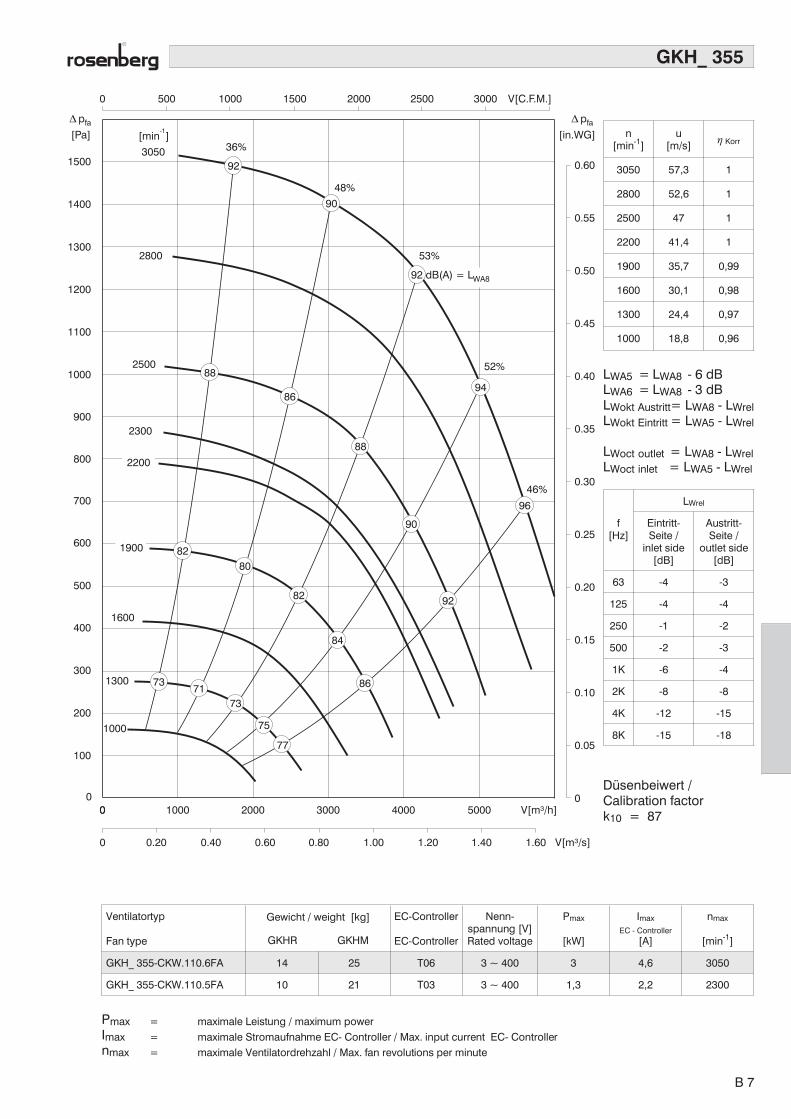
GKH_ 355
[Pa] [in.WG]
pfa� pfa�
100
200
300
400
500
600
700
800
900
1000
1100
1200
1300
1400
15003050
2800
2500
1600
1300
1000
[min ]-1
00
0
0.05
0.10
0.15
0.20
0.25
0.30
0.35
0.40
0.45
0.50
0.55
0.60
36%
48%
52%
46%
53%
0
0 0.20 0.40 0.60 0.80 1.00 1.20 1.40 1.60 V[m³/s]
1000 2000 3000 4000 5000 V[m³/h]
0 500 1000 1500 2000 2500 3000 V[C.F.M.]
1900
2200
2300
7371
73
75
77
86
84
82
8082
92
90
96
94
90
92
88
86
88
92 dB(A) = LWA8
Ventilatortyp
Fan type
Gewicht / weight [kg]
GKHR GKHM
EC-Controller
EC-Controller
Nenn-spannung [V]Rated voltage
Pmax
[kW]
Imax
EC - Controller[A]
nmax
[min-1]
GKH_ 355-CKW.110.6FA 14 25 T06 3 ~ 400 3 4,6 3050
GKH_ 355-CKW.110.5FA 10 21 T03 3 ~ 400 1,3 2,2 2300
Pmax = maximale Leistung / maximum powerImax = maximale Stromaufnahme EC- Controller / Max. input current EC- Controllernmax = maximale Ventilatordrehzahl / Max. fan revolutions per minute
n[min-1]
u[m/s]
� Korr
3050 57,3 1
2800 52,6 1
2500 47 1
2200 41,4 1
1900 35,7 0,99
1600 30,1 0,98
1300 24,4 0,97
1000 18,8 0,96
LWA5 = LWA8 - 6 dBLWA6 = LWA8 - 3 dBLWokt Austritt= LWA8 - LWrelLWokt Eintritt = LWA5 - LWrel
LWoct outlet = LWA8 - LWrelLWoct inlet = LWA5 - LWrel
f[Hz]
LWrel
Eintritt-Seite /
inlet side[dB]
Austritt-Seite /
outlet side[dB]
63 -4 -3
125 -4 -4
250 -1 -2
500 -2 -3
1K -6 -4
2K -8 -8
4K -12 -15
8K -15 -18
Düsenbeiwert /Calibration factork10 = 87
B 7
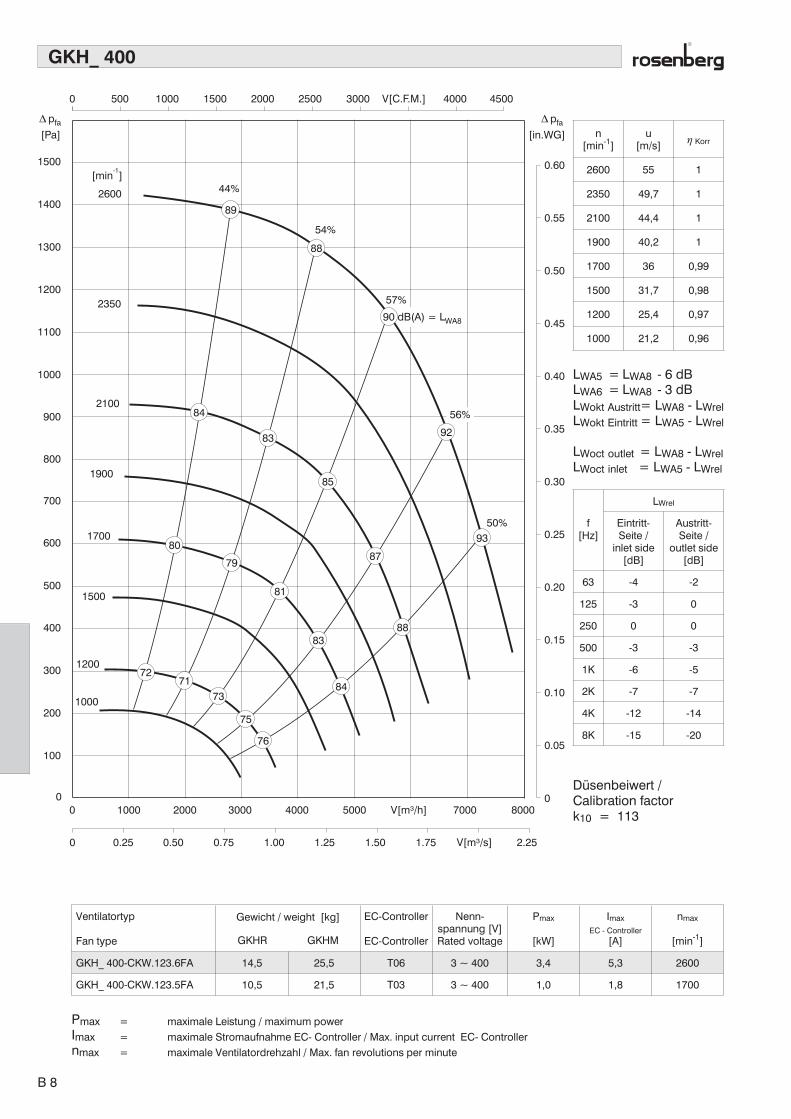
GKH_ 400
[Pa] [in.WG]
pfa� pfa�
100
200
300
400
500
600
700
800
900
1000
1100
1200
1300
1400
[min ]-1
2600
2350
2100
1900
1700
1500
1200
1000
44%
54%
57%
1500
0 0
0.05
0.10
0.15
0.20
0.25
0.30
0.35
0.40
0.45
0.50
0.55
0.60
0 500 1000 1500 2000 2500 3000 V[C.F.M.] 4000 4500
0
0 0.25 0.50 0.75 1.00 1.25 1.50 1.75 V[m³/s] 2.25
1000 2000 3000 4000 5000 V[m³/h] 7000 8000
56%
50%
84
83
85
87
88
93
92
88
89
7271
73
75
76
80
79
81
83
84
90 dB(A) = LWA8
Ventilatortyp
Fan type
Gewicht / weight [kg]
GKHR GKHM
EC-Controller
EC-Controller
Nenn-spannung [V]Rated voltage
Pmax
[kW]
Imax
EC - Controller[A]
nmax
[min-1]
GKH_ 400-CKW.123.6FA 14,5 25,5 T06 3 ~ 400 3,4 5,3 2600
GKH_ 400-CKW.123.5FA 10,5 21,5 T03 3 ~ 400 1,0 1,8 1700
Pmax = maximale Leistung / maximum powerImax = maximale Stromaufnahme EC- Controller / Max. input current EC- Controllernmax = maximale Ventilatordrehzahl / Max. fan revolutions per minute
n[min-1]
u[m/s]
� Korr
2600 55 1
2350 49,7 1
2100 44,4 1
1900 40,2 1
1700 36 0,99
1500 31,7 0,98
1200 25,4 0,97
1000 21,2 0,96
LWA5 = LWA8 - 6 dBLWA6 = LWA8 - 3 dBLWokt Austritt= LWA8 - LWrelLWokt Eintritt = LWA5 - LWrel
LWoct outlet = LWA8 - LWrelLWoct inlet = LWA5 - LWrel
f[Hz]
LWrel
Eintritt-Seite /
inlet side[dB]
Austritt-Seite /
outlet side[dB]
63 -4 -2
125 -3 0
250 0 0
500 -3 -3
1K -6 -5
2K -7 -7
4K -12 -14
8K -15 -20
Düsenbeiwert /Calibration factork10 = 113
B 8

GKH_ 450
1100
[min ]-1
2050 43%
54%
55%
50%
57%1850
1650
1350
1200
900
[Pa] [in.WG]
pfa� pfa�
0 500 1000 1500 2000 2500 3000 V[C.F.M.] 4000 4500
1000
900
800
700
600
500
400
300
200
100
00
0 0.25 0.50 0.75 1.00 1.25 1.50 1.75 V[m³/s]2.252.00
1000 2000 3000 4000 5000 6000 V[m³/h]7000 80000
0.50
1.00
1.50
2.00
2.50
3.00
3.50
4.00
4.50
1500
1050 7372
74
76
77
83
82
80
83
88
89
82
84
86
87
92
91
78
79
87 dB(A) = LWA8
Ventilatortyp
Fan type
Gewicht / weight [kg]
GKHR GKHM
EC-Controller
EC-Controller
Nenn-spannung [V]Rated voltage
Pmax
[kW]
Imax
EC - Controller[A]
nmax
[min-1]
GKH_ 450-CKW.138.6FA 15,5 31 T06 3 ~ 400 3,1 4,9 2050
Pmax = maximale Leistung / maximum powerImax = maximale Stromaufnahme EC- Controller / Max. input current EC- Controllernmax = maximale Ventilatordrehzahl / Max. fan revolutions per minute
n[min-1]
u[m/s]
� Korr
2050 48,7 1
1850 44 1
1650 39,2 1
1500 35,7 1
1350 32,1 0,99
1200 28,5 0,98
1050 25 0,97
900 21,4 0,96
LWA5 = LWA8 - 6 dBLWA6 = LWA8 - 3 dBLWokt Austritt= LWA8 - LWrelLWokt Eintritt = LWA5 - LWrel
LWoct outlet = LWA8 - LWrelLWoct inlet = LWA5 - LWrel
f[Hz]
LWrel
Eintritt-Seite /
inlet side[dB]
Austritt-Seite /
outlet side[dB]
63 -4 -2
125 -3 0
250 0 0
500 -3 -3
1K -6 -5
2K -7 -7
4K -12 -14
8K -15 -20
Düsenbeiwert /Calibration factork10 = 145
B 9
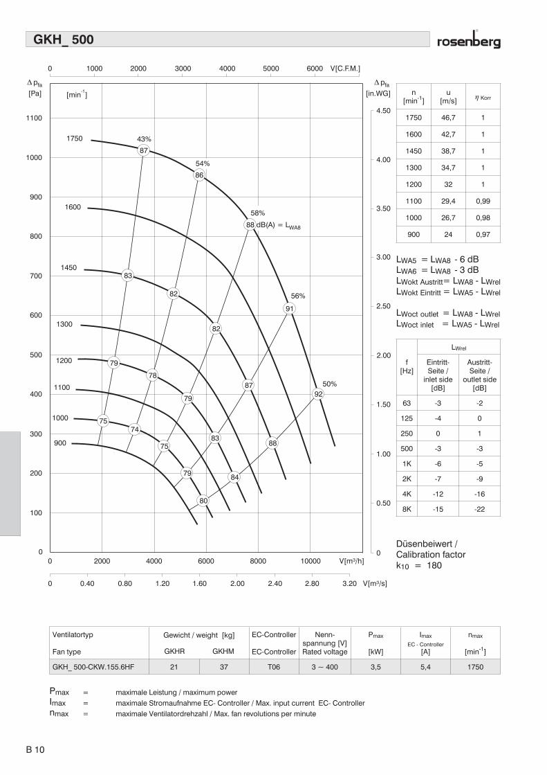
GKH_ 500
1100
1750 43%
1600
1450
[min ]-1[Pa] [in.WG]
pfa� pfa�
1000
900
800
700
6001300
1200
1100
1000
900
500
400
300
200
100
0 0
0.50
1.00
1.50
2.00
2.50
3.00
3.50
4.00
4.50
0
0 0.40 0.80 1.20 1.60 2.00 2.40 2.80 3.20 V[m³/s]
2000 4000 6000 8000 10000 V[m³/h]
0 1000 2000 3000 4000 5000 6000 V[C.F.M.]
56%
50%
54%
91
86
87
7574
75
79
80
84
88
8792
82
82
83
83
79
78
79
88 dB(A) = LWA8
58%
Ventilatortyp
Fan type
Gewicht / weight [kg]
GKHR GKHM
EC-Controller
EC-Controller
Nenn-spannung [V]Rated voltage
Pmax
[kW]
Imax
EC - Controller[A]
nmax
[min-1]
GKH_ 500-CKW.155.6HF 21 37 T06 3 ~ 400 3,5 5,4 1750
Pmax = maximale Leistung / maximum powerImax = maximale Stromaufnahme EC- Controller / Max. input current EC- Controllernmax = maximale Ventilatordrehzahl / Max. fan revolutions per minute
n[min-1]
u[m/s]
� Korr
1750 46,7 1
1600 42,7 1
1450 38,7 1
1300 34,7 1
1200 32 1
1100 29,4 0,99
1000 26,7 0,98
900 24 0,97
LWA5 = LWA8 - 6 dBLWA6 = LWA8 - 3 dBLWokt Austritt= LWA8 - LWrelLWokt Eintritt = LWA5 - LWrel
LWoct outlet = LWA8 - LWrelLWoct inlet = LWA5 - LWrel
f[Hz]
LWrel
Eintritt-Seite /
inlet side[dB]
Austritt-Seite /
outlet side[dB]
63 -3 -2
125 -4 0
250 0 1
500 -3 -3
1K -6 -5
2K -7 -9
4K -12 -16
8K -15 -22
Düsenbeiwert /Calibration factork10 = 180
B 10
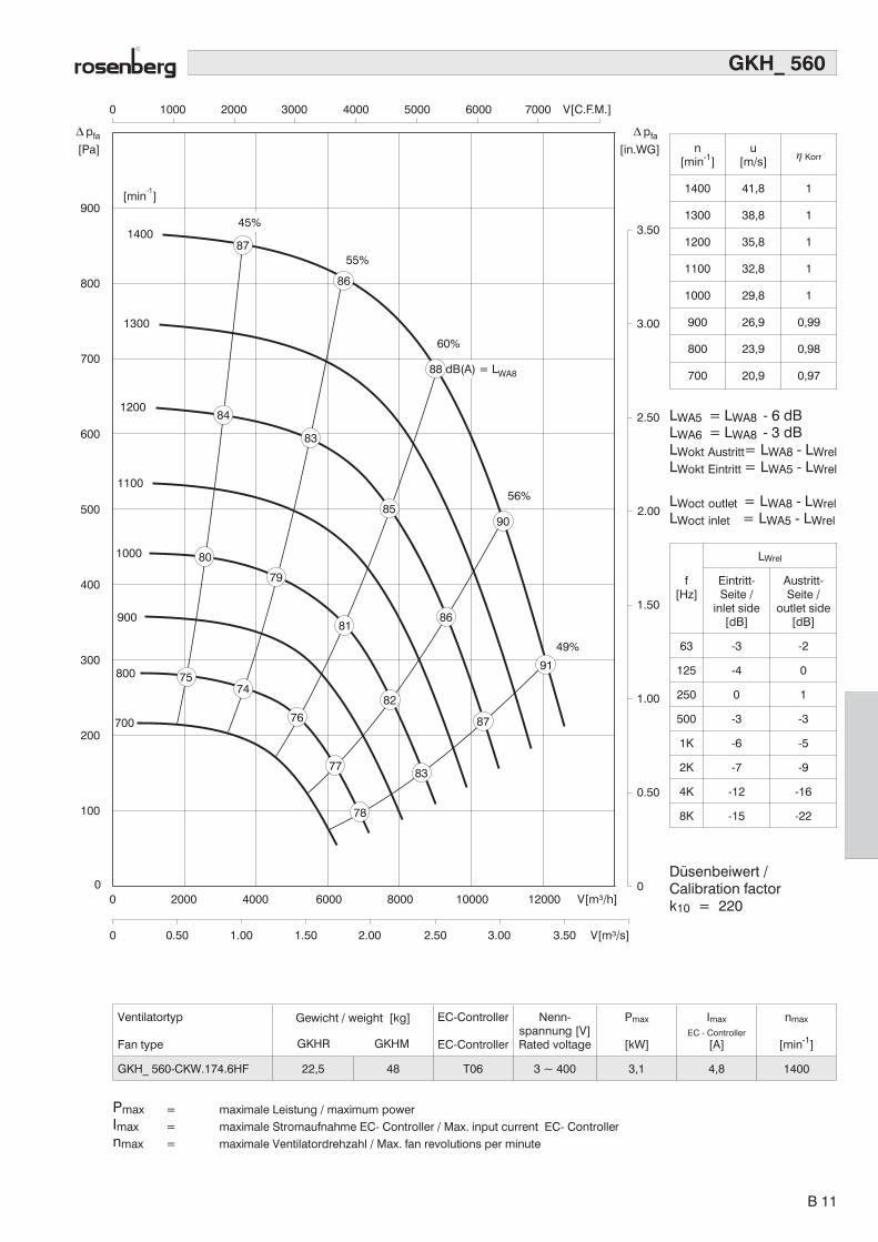
GKH_ 560
[min ]-1
[Pa] [in.WG]
pfa� pfa�
900
1400
1300
1200
1100
1000
900
800
700
55%
60%
56%
49%
800
700
600
500
400
300
200
100
0 0
0.50
1.00
1.50
2.00
2.50
3.00
3.50
0
0 0.50 1.00 1.50 2.00 2.50 3.00 3.50 V[m³/s]
2000 4000 6000 8000 10000 12000 V[m³/h]
0 1000 2000 3000 4000 5000 6000 7000 V[C.F.M.]
45%
7574
80
81
76
79
82
87
91
90
86
85
83
84
86
87
8377
78
88 dB(A) = LWA8
Ventilatortyp
Fan type
Gewicht / weight [kg]
GKHR GKHM
EC-Controller
EC-Controller
Nenn-spannung [V]Rated voltage
Pmax
[kW]
Imax
EC - Controller[A]
nmax
[min-1]
GKH_ 560-CKW.174.6HF 22,5 48 T06 3 ~ 400 3,1 4,8 1400
Pmax = maximale Leistung / maximum powerImax = maximale Stromaufnahme EC- Controller / Max. input current EC- Controllernmax = maximale Ventilatordrehzahl / Max. fan revolutions per minute
n[min-1]
u[m/s]
� Korr
1400 41,8 1
1300 38,8 1
1200 35,8 1
1100 32,8 1
1000 29,8 1
900 26,9 0,99
800 23,9 0,98
700 20,9 0,97
LWA5 = LWA8 - 6 dBLWA6 = LWA8 - 3 dBLWokt Austritt= LWA8 - LWrelLWokt Eintritt = LWA5 - LWrel
LWoct outlet = LWA8 - LWrelLWoct inlet = LWA5 - LWrel
f[Hz]
LWrel
Eintritt-Seite /
inlet side[dB]
Austritt-Seite /
outlet side[dB]
63 -3 -2
125 -4 0
250 0 1
500 -3 -3
1K -6 -5
2K -7 -9
4K -12 -16
8K -15 -22
Düsenbeiwert /Calibration factork10 = 220
B 11

GKHR ... W
øD
E
øD
4
øD
øD
6
øD
3
øD
1
øD
2
A
H G
øD
7
t
h70
a
B E
C
D54 * 90°
Ventilator / fan A B C H D a D4 D5 E D6 h DE D3 D2 D1 D7 G t
GKHR 280-CSW.087 133 169 216 87 284 6,5 100 M6 115 188 5 174 250 307 286/6*60° 7 52 1,5
GKHR 315-CSW.098 146 182 236 98 319 6,5 100 M6 115 212 5,5 195 282 348 320/6*60° 11 59 1,5
GKHR 355-CSW.110 164 211 272 110 359 6 140 M10 162 238 6 219 315 382 356/6*60° 11 67 1,5
GKHR 400-CSW.123 184 231 300 123 404 6 140 M10 162 267 7 248 355 422 395/8*45° 11 76 1,5
GKHR 450-CSW.138 209 244 318 138 454 6 140 M10 162 300 8 277 400 464 438/8*45° 11 82 1,5
GKHR 500-CSW.155 234 270 359 155 510 6 140 M10 162 337 9 310 450 515 490/8*45° 11 98 1,5
GKHR 560-CSW.174 262 296 391 174 570 6 140 M10 162 377 10 348 500 564 541/8*45° 11 105 1,5
B 12
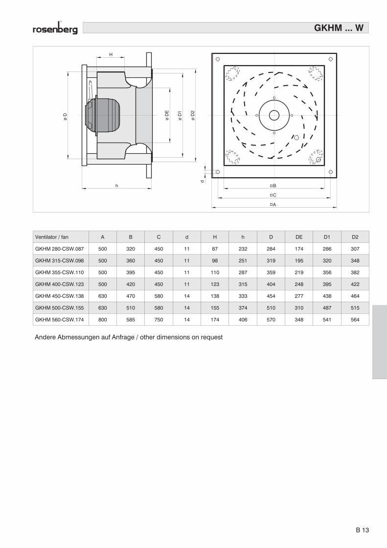
GKHM ... W
C
B
A
øD
øD
1
øD
2
F
a
h
H
øD
E
d
Ventilator / fan A B C d H h D DE D1 D2
GKHM 280-CSW.087 500 320 450 11 87 232 284 174 286 307
GKHM 315-CSW.098 500 360 450 11 98 251 319 195 320 348
GKHM 355-CSW.110 500 395 450 11 110 287 359 219 356 382
GKHM 400-CSW.123 500 420 450 11 123 315 404 248 395 422
GKHM 450-CSW.138 630 470 580 14 138 333 454 277 438 464
GKHM 500-CSW.155 630 510 580 14 155 374 510 310 487 515
GKHM 560-CSW.174 800 585 750 14 174 406 570 348 541 564
Andere Abmessungen auf Anfrage / other dimensions on request
B 13

Elektronische Kommutierungseinheit
AusführungDie elektronische Kommutierungseinheit besitzt einMetallgehäuse in Schutzart IP 20; geeignet für Schalt-schrankeinbau. Bei der Montage sind Mindestabstände(siehe Betriebsanleitung) einzuhalten. Die zulässigeUmgebungstemperatur beträgt +40°C. Die elektroni-schen Kommutierungseinheiten sind mit Funkentstörfilterund Netzdrossel ausgestattet und entsprechen der EMV-Richtlinie 89/336/ EWG. In der Betriebsanleitung sind diespeziellen Maßnahmen angegeben, welche bauseits zurEinhaltung der EMV getroffen werden müssen.
FunktionenDrehzahlvorgabe durch externes 0-10 Volt Eingangs-signal bzw. über eingebautes Potentiometer. Ein-,Ausschaltmöglichkeit durch externe Freigabe. Maximal-drehzahlvorgabe durch interne Steckschalter. EinfacheDrehrichtungsumschaltung durch Einlegen einer Brüc-ke an der Steckleiste. Störung und Betriebsmeldungdurch zwei auf der Geräteoberseite eingebaute LED´sund über Melderelais. Umfangreiche Überwachungs- undSchutzfunktionen für Motorstrom, Phasenausfall undÜberstrom.
Electronic Commutating Unit
DesignThe electronic commutating unit is contained in a metalcasing with IP 20 protection; loose, so appropriate forinstallation in a control box. Please observe the minimumclearance requirements as indicated in the operating ma-nual. The permitted ambient temperature is +40° C. Theelectronic commutating units are fitted with radio inter-ference filters and electrical supply power chokes in ac-cordance with EMC Directive 89/336/EEC. The operatingmanual provides for special measures to be taken duringinstallation to ensure that the EMC Directives are met.
FunctionsSpeed control can be set with external 0-10 Volt inputsignal or with integrated potentiometer. The unit can beswitched on or off with an external command signal. Themaximum speed can be set with an internal jumper. Thedirection can be simply reversed by putting a bridgejumper on the connector panel. Failure and operatingmode is displayed with two LED’s incorporated into thetop of the unit. A wide range of control and protectionfunctions for motor current, phase failure, and overcurrent.
Technische Daten Specification T03 T04 T06
Nennspannung 50/60Hz Input voltage 50/60 Hz V 3 * 400 3 * 400 3 * 400
Nennstrom maximal Rated current max. approx. A 3 4,5 6,7
Ausgangsleistung maximal Output power max. approx. kW 1,8 2,4 3,6
Drehzahlvorgabe über 0 - 10 V Speed setting via 0 - 10 V V � � ü
Melderelais Störung Signal for fault � ü ü
Melderelais Betrieb Signal for operation � ü ü
Umschaltung Hand / Auto Manual / automatic switchover � ü ü
max. Drehzahlvorgabeam Gerät
Manual speed setting by integralpotentiometer
� ü ü
Einstellung nmin / nmax Setting nmin / nmax � ü ü
Gehäuseschutzart Housing protection IP 20 IP 20 IP 20
Umgebungstemperatur Ambient temperature °C -10°C - +40 °C -10°C - +40 °C -10°C - +40 °C
Abmessungen B x H x T Dimensions mm 145 x 300 x 165 145 x 300 x 165 145 x 300 x 165
B 14
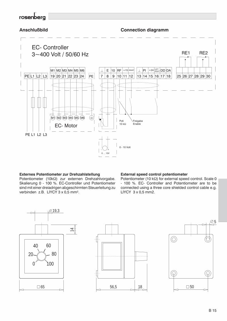
Anschlußbild Connection diagramm
L3
M1
19L2L1PE
E 10 RF +15 PI +24 LEFTRIGHT DD DARESETM2
20
M3
21
M4
22
M5
23
M6
PE24 7 8 9 10 11 12 13 14 15 16 17 18 25 26 27 28 29 30
M1 M2 M3 M4 M5 M6
L3L2L1PE
EC- Motor
RE1 RE2
Poti10 kΩ
0 - 10 Volt
0 … 10V
+-
FreigabeEnable
EC- Controller3~400 Volt / 50/60 Hz
Externes Potentiometer zur DrehzahlstellungPotentiometer (10k�) zur externen Drehzahlvorgabe.Skalierung 0 - 100 %. EC-Controller und Potentiometersind mit einer dreiadrigen abgeschirmten Steuerleitung zuverbinden z.B. LIYCY 3 x 0,5 mm².
20
40 60
80
1000
14
65
19,3
56,5 18 50
5
External speed control potentiometerPotentiometer (10 k�) for external speed control. Scale 0- 100 %. EC- Controller and Potentiometer are to beconnected using a three core shielded control cable e.g.LIYCY 3 x 0,5 mm2.
B 15
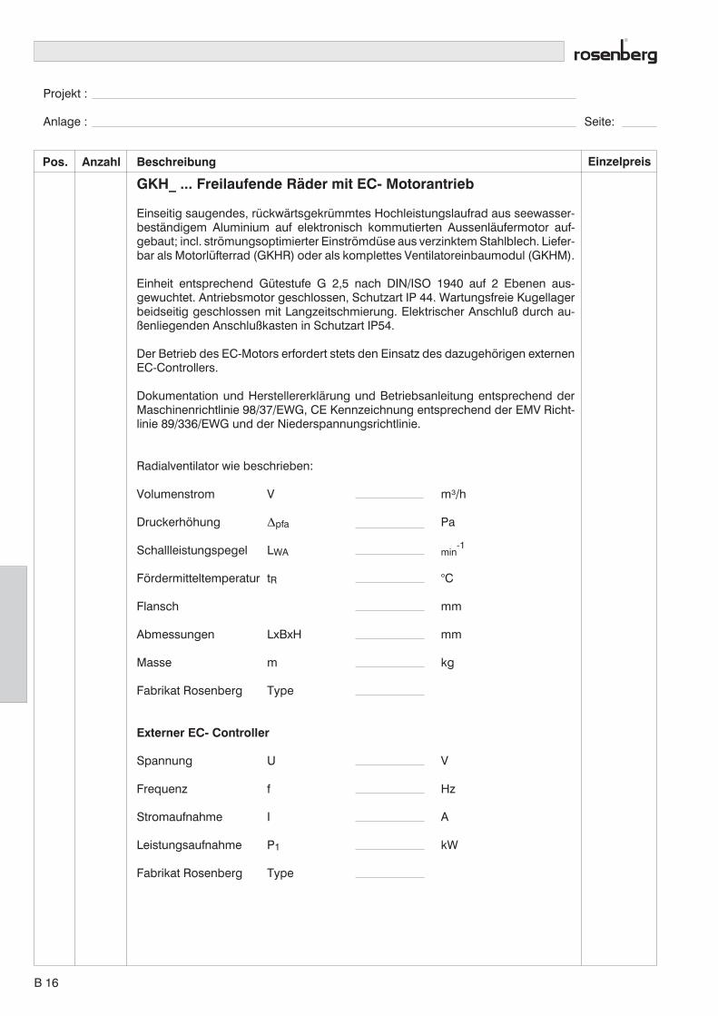
Projekt :
Anlage : Seite:
Pos. Anzahl EinzelpreisBeschreibung
GKH_ ... Freilaufende Räder mit EC- Motorantrieb
Einseitig saugendes, rückwärtsgekrümmtes Hochleistungslaufrad aus seewasser-beständigem Aluminium auf elektronisch kommutierten Aussenläufermotor auf-gebaut; incl. strömungsoptimierter Einströmdüse aus verzinktem Stahlblech. Liefer-bar als Motorlüfterrad (GKHR) oder als komplettes Ventilatoreinbaumodul (GKHM).
Einheit entsprechend Gütestufe G 2,5 nach DIN/ISO 1940 auf 2 Ebenen aus-gewuchtet. Antriebsmotor geschlossen, Schutzart IP 44. Wartungsfreie Kugellagerbeidseitig geschlossen mit Langzeitschmierung. Elektrischer Anschluß durch au-ßenliegenden Anschlußkasten in Schutzart IP54.
Der Betrieb des EC-Motors erfordert stets den Einsatz des dazugehörigen externenEC-Controllers.
Dokumentation und Herstellererklärung und Betriebsanleitung entsprechend derMaschinenrichtlinie 98/37/EWG, CE Kennzeichnung entsprechend der EMV Richt-linie 89/336/EWG und der Niederspannungsrichtlinie.
Radialventilator wie beschrieben:
Volumenstrom V m³/h
Druckerhöhung �pfa Pa
Schallleistungspegel LWA min-1
Fördermitteltemperatur tR °C
Flansch mm
Abmessungen LxBxH mm
Masse m kg
Fabrikat Rosenberg Type
Externer EC- Controller
Spannung U V
Frequenz f Hz
Stromaufnahme I A
Leistungsaufnahme P1 kW
Fabrikat Rosenberg Type
B 16

Project :
Plant : Page:
Pos. Quan. Single priceDescription
GKH_ ... Free- running impeller with ec- motor drive
Single inlet, backward curved high efficiency impeller made of sea- waterproofaluminium, mounted onto the electronic commutated external rotor motor,equipped with an air flow optimized inlet cone made of galvanized sheet steel. Theimpeller can be supplied as a single unit or as a complete module made of gal-vanized sheet steel.
The fan is balanced on two levels according quality class G 2,5, DIN/ISO 1940.Closed motor, protection class IP 44 . Maintenance free ball bearings, closed onboth sides, sealed for life. Electrical connection through terminal box in IP 54.
The operation of an EC motor always requires the use of a matching commutatingunit (EC-controller).
Documentation: Manufacturers declaration and operating instruction are accordingto machinery directive 98/37/EEC, CE identification in accordance to EMC- directive89/336/EEC and low voltage directive 73/23/EEC.
Centrifugal fan with free- running impeller as described before:
Air volume flow V m³/h
Pressure increase �pfa Pa
Sound power level LWA min-1
Temperature of ventilated med. tR °C
Flange mm
Dimensions LxBxH mm
Weight m kg
Rosenberg product Type
Externer EC- Controller
Voltage U V
Frequency f Hz
Current consumption I A
Power consumption P1 kW
Rosenberg product Type
B 17
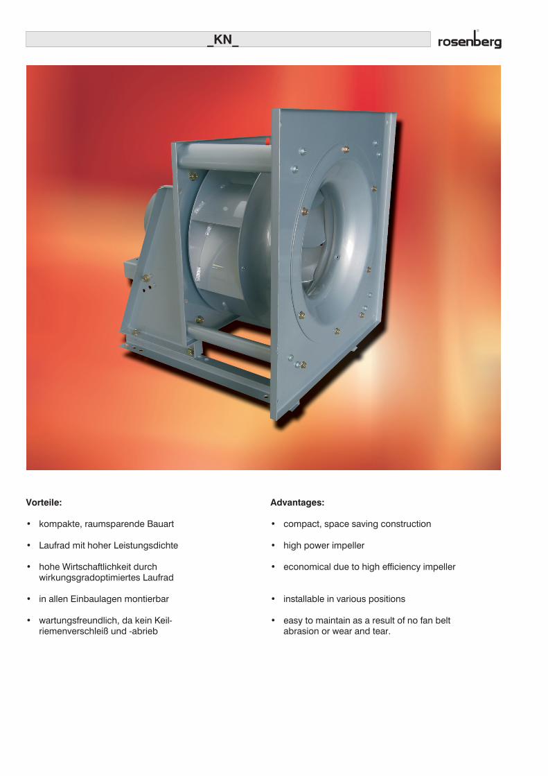
_KN_
Vorteile:
• kompakte, raumsparende Bauart
• Laufrad mit hoher Leistungsdichte
• hohe Wirtschaftlichkeit durchwirkungsgradoptimiertes Laufrad
• in allen Einbaulagen montierbar
• wartungsfreundlich, da kein Keil-riemenverschleiß und -abrieb
Advantages:
• compact, space saving construction
• high power impeller
• economical due to high efficiency impeller
• installable in various positions
• easy to maintain as a result of no fan beltabrasion or wear and tear.

Kennliniendarstellung / Performance Curves
Freilaufende Räder mit IEC- Normmotor
Die Kennliniendarstellung zeigt die statische Drucker-höhung �pfa als Funktion des Volumenstroms. DieKennlinien beziehen sich auf eine Luftdichte von 1,2kg/m3.
Free blowing fan with standard IEC- motor
The performance curve indicates the static pressure in-crease �pfa as a function of the volume flow. The per-formance curves refer to an air density of 1,2 kg/m3.
2200
520053%
64%
69%
65%
55%
4900
4000
[min ]-1
[Pa] [in.WG]
pfa� pfa�
2000
1800
1600
1400
1200
1000
800
600
400
200
0 0
1.00
2.00
3.00
4.00
5.00
6.00
7.00
8.00
9.00
2,2
1,5kW1,1
0,37
0 500 1000 1500 V[C.F.M.]25002000
00
0 0.20 0.40 0.60 0.80 1.00 1.40V[m³/s]
500 1000 1500 2000 2500 3000 V[m³/h]3500 4000 5000
n = 5200 minmax
-1
0,750,55
4600
4300
3700
3400
3000
2600
2200
1800
1500
93
93
91
90
8988
87
86
87
88
91
94
84
84
79
71
7069
7071
78
77
7879
83
82
83
90
94
92 dB(A) = LWA8
n[min-1]
u[m/s]
� Korr
5200 68,6 1
4900 64,7 1
... ... ...
1 2 3
1 Kennlinien konstanter Drehzahl /performance curves at constant speed
2 Umfangsgeschwindigkeit / radial speed
3 Wirkungsgradkorrektur /correction of efficiency
4 Schallleistungspegel LWA8 /sound power level
5 Wirkungsgrad / efficiency
6 Kennlinie bei unterschiedl. Drehzahlen /performance curve at various speeds
7 Statischer Druck / static pressure
8 Luftvolumenstrom / air volume
9 Leistungsbedarf Laufrad / shaft power
7
6
8
4
5
9
Formelzeichen / Technical Formula
Benennung / DescriptionEinheit/ Unit
U Nennspannung / Rated voltage V
PmaxMotoraufnahmeleistung / Motor powerconsumption
kW
Imax Nennstrom / Rated current A
nmax Ventilatordrehzahl / Fan speed min-1
tRmax. zulässige Fördermitteltemperatur / max.permissible medium temperature
°C
� pfa statische Druckerhöhung / static pressure increase Pa
LWA A - Schallleistungspegel / A - sound power level dB(A)
Benennung / DescriptionEinheit/ Unit
LWrelrelativer Schallleistungspegel / relative soundpower level
dB
LWOktOktav - Schallleistungspegel / Octave soundpower level
dB(A)
LWA5Freiansaug-Schallleistungspegel / Free inlet soundpower level
dB(A)
LWA6Freiausblas-Schallleistungspegel / Free outletsound power level
dB(A)
LWA8Gehäuse- u. Freiausblas-Schallleistungspegel /Casing and free-outlet sound power level
dB(A)
C 1

Eigenschaften und Ausführungen
Die Rosenberg Radialventilatoren mit freilaufendemRad der Baureihen DKN_ sind für den Geräteeinbaukonzipiert und in folgenden Ausführungen lieferbar:
• DKNB
• DKNM
MotorenIEC-Drehstrom-Normmotoren in Bauform IMB3 bzw.IMB5. Schutzart IP55, 400V/50Hz, Wärmeklasse F. DieMotoren sind für den Betrieb mit Frequenzumrichtergeeignet. Bei Inbetriebnahme und Wartung sind die de-tailierten Angaben des Motorherstellers vor allem hin-sichtlich bauseits vorzusehender Motorschutzeinricht-ungen zu beachten.
MotorschutzAlle Motoren haben in der Wicklung eingelegte Kaltleiter(Motoren mit Thermokontakten auf Anfrage), die selbst-tätig die Wicklungstemperatur des Motors überwachen.Bei ordnungsgemäßem Anschluß schützen sie die Motor-wicklung vor Überlastung, Ausfall einer Netzphase,Festbremsen des Motors und vor zu hohen Förder-mitteltemperaturen. Die von uns angebotenen Motor-schutzschaltgeräte beinhalten in der Ausführung MSD1 Kdie Motorschutzeinrichtung in Verbindung mit Kaltleitern.In der Regel können die Kaltleiter auch direkt am ver-wendeten Frequenzumrichter angeschlossen werden.
Elektrischer AnschlußDer Motorklemmenkasten ist leicht zugänglich. Ent-sprechend des Klemmbrettschaltbildes (siehe Seite C18Anschlußbilder) ist der Motor an die vorhandene Spann-ungsversorgung anzuschließen. Dabei sind die geltendenBestimmungen, unter Beachtung der örtlichen Vorschrif-ten zu beachten. Bei Betrieb über Frequenzumrichter istdie jeweilige Betriebsanleitung zu beachten.
Features and Construction
Rosenberg centrifugal fans with free running impellerof the DKN_ ranges are designed for installation andoperation in AHUs. They can be supplied as follows:
• DKNB
• DKNM
MotorsStandard IEC three phase motors in size IMB3 re-spectively IMB5, protection class IP55, 400V/50Hz,insulation class F. The motors are suitable for operationwith frequency converter. Before initial operation andduring maintenance, the detailed instructions of the motorsupplier regarding motor protection installations whichre- quired on site, have to be followed.
Motor protectionAll motors are equipped with PTC (thermal contactsavailable on request) control the temperature of the motor.If wired correctly, they protect the motor from overload,breakdown of one phase, locking of the motor, and toohigh air temperatures. Rosenberg offers motor protectionswitches. Version MSD1 K allows a connection of themotor’s PTC cores. The cores can usually also be wiredto a frequency converter.
Electrical ConnectionThe wiring box of the motor is easily accessable. Themotor has to be connected according to the wiringdiagram (see on page C18 Connection diagram) and inaccordance with valid regulations and local laws. In caseof operation with frequency transformer, please check theoperation manual.
Ventilatormodul mit Motorbock und Grund-rahmen. Einströmdüse eingeschraubt und opti-male Eintauchtiefe einjustiert. Gesamte Einheitdurch Schwingungs- oder Federdämpferele-mente entkoppelt aufstellbar. Antriebsmotor inBauart IMB3, IMB5-Ausführung auf Anfrage.Standardausführung für Einbau mit horizontalerMotorwelle, durch zusätzliche Trageschienekann Modul auch hängend mit vertikaler Motor-welle eingesetzt werden.
Ventilatormodul ohne Grundrahmen. Einström-düse eingeschraubt und optimale Eintauchtiefeeinjustiert. Antriebsmotor in Bauart IMB5.
Fan module with motor support and base frame.Inlet cone mounted and adjusted to correctdepth. Complete unit installable with vibrationdampers or springs. Motor in version IMB3. IMB5available on request. Unit to be installed withhorizontal shaft in standard version. Vertical in-stallation with additional support bar.
Fan module without base frame. Inlet conemounted and adjusted to correct depth. MotorIMB5.
C 2

DrehzahlsteuerungDie anlagenspezifisch geforderte optimale Einstellungdes gewünschten Betriebspunktes kann nur durch eingeeignetes System zur Drehzahlveränderung realisiertwerden.
Die Drehzahländerung erfolgt durch Verändern derFrequenz mit einem Frequenzumrichter. In den tech-nischen Daten für die Ventilatoren ist die maximalmögliche Frequenz für den jeweils zugeordneten Motor-typ dargestellt. Motorzuordnung wurde unter Berück-sichtigung von Motorleistungsreserven durchgeführt. Beihöheren Frequenzen als fmax wird der Motor thermischüberlastet, sodaß die Temperaturfühler nach entsprech-ender Erwärmungszeit ansprechen werden. Die amFrequenzumrichter einzustellende Eckfrequenz beträgtfür alle Ventilatoren 50 Hz. Für Notbetrieb oder Ausfall desFrequenzumrichter können alle Ventilatoren auch direktbei 400V am 50Hz-Netz betrieben werden. Bei Betrieb derMotoren am Frequenzumrichter darf die maximaleSpannungssteilheit von 500V/�s nicht überschritten wer-den. Je nach verwendetem FU und der Leitungslängezwischen Motor und FU sind Zusatzkomponentenvorzusehen (z.B. Sinusfilter).
Motoren mit aufgebautem FrequenzumrichterAls Alternative zum IEC-Motor plus separatem Fre-quenzumrichter sind für die DKNB/DKNM Ventilatoren bisBaugröße 630 auch Antriebsmotoren mit aufgebautem FUverfügbar.
Durch den integrierten FU vereinfacht sich der Ver-drahtungsaufwand, man kann auf abgeschirmte Motor-zuleitungen verzichten und der benötigte Platzbedarf z.B.für eine komplette Klimageräteregelung verringert sichsehr stark.
Die Zuordnung der Motoren mit integriertem FU erfolgtanalog zur Auswahl von Standard IEC-Motoren. VonBaugröße 80 bis Baugröße 132 stehen alle FU-Motoren in2- und 4-poliger Ausführung mit den bekannten Leist-ungsabstufungen zur Verfügung.
Speed controlThe installation specific optimal adjustment for the re-quired operating point can only be realised with a suitablespeed control system.
The speed is changed by changing the frequency with afrequency converter. The highest possible frequency forthe determined motortype can be found in the technicaldata of the fans. The motor selection is based on thepower reserves of the motor. At higher frequencies thanfmax the motor will thermally overload and the tempera-ture sensor will react after a certain period of heating up.The cut-off frequency adjustable on the frequency con-verter is 50Hz for all fans. In case of an emergency orfailure of the frequency converter, all fans can be operatedat 400V, 50Hz main supply. When the motors are operatedby frequency converter the max. speed of voltageincrease of 500V/�s should not be exceeded. Dependingon the type of frequency converter, and the length of thecable between motor and frequency converter, additionalcomponents must be provided, such as a sinus filter.
Motors with integrated frequency converterNormally frequency converters are separated from theIEC-motor. As a space saving alternative we offer motorswith integrated frequency converters up to fan size 630.
Advantages are also wiring requirements, no need forshielded leads, space requirements of the AHU’s com-plete control unit are minimal.
The allocation of the motors with integrated frequencyconverter analogous to the standard IEC-motor. All mo-tors with integrated frequency converter of the sizes 80 to132 are available in 2- pole respectively 4-pole versions.
C 3

2200
520053%
64%
69%
65%
55%
4900
4000
[min ]-1
[Pa] [in.WG]
pfa� pfa�
2000
1800
1600
1400
1200
1000
800
600
400
200
0 0
1.00
2.00
3.00
4.00
5.00
6.00
7.00
8.00
9.00
2,2
1,5kW1,1
0,37
0 500 1000 1500 V[C.F.M.]25002000
00
0 0.20 0.40 0.60 0.80 1.00 1.40V[m³/s]
500 1000 1500 2000 2500 3000 V[m³/h]3500 4000 5000
n = 5200 minmax
-1
0,750,55
4600
4300
3700
3400
3000
2600
2200
1800
1500
93
93
91
90
8988
87
86
87
88
91
94
84
84
79
71
7069
7071
78
77
7879
83
82
83
90
94
92 dB(A) = LWA8
Typenbezeichnung MotortypnN
[min-1]PN
[kW]IN[A]
fmaxHz]
nmax[min-1]
Gewicht / Weight [kg]DKNB / DKNM
DKN_ 250-2KW.078.A07-001 71-2 2800 0,55 1,36 55 3080 a.A. a.A.
DKN_ 250-2KW.078.A08-001 80-2 2855 0,75 1,73 60 3425 20 a.A.
DKN_ 250-2KW.078.A08-002 80-2 2845 1,1 2,4 68 3780 21 a.A.
DKN_ 250-2KW.078.A09-001 90S-2 2860 1,5 3,25 75 4290 a.A. a.A.
DKN_ 250-2KW.078.A09-001 90L-2 2880 2,2 4,6 85 4900 a.A. a.A.
DKN_ 250-2KW.078.A10-001 100L-2 2895 3,0 6,1 89 5200 a.A. a.A.
a.A. = auf Anfrage / on request
DKN_ 250
n[min-1]
u[m/s]
� Korr
5200 68,6 1
4900 64,7 1
4600 60,7 1
4300 56,7 0,99
4000 52,8 0,99
3700 48,8 0,99
3400 44,9 0,99
3000 39,6 0,98
2600 34,3 0,98
2200 29 0,98
1800 23,8 0,97
1500 19,8 0,97
LWA5 = LWA8 - 6 dBLWA6 = LWA8 - 3 dBLWokt Austritt= LWA8 - LWrelLWokt Eintritt = LWA5 - LWrel
LWoct outlet = LWA8 - LWrelLWoct inlet = LWA5 - LWrel
f[Hz]
LWrel
Eintritt-Seite /
inlet side[dB]
Austritt-Seite /
outlet side[dB]
63 -11 -8
125 -8 -11
250 -1 -4
500 -4 -4
1K -6 -4
2K -7 -7
4K -9 -11
8K -16 -18
Düsenbeiwert / calibra-tion factor k10 = 46
C 4
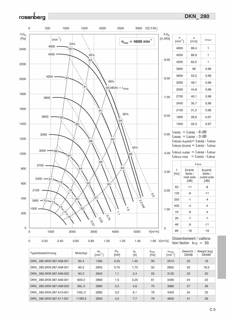
2200
2400
[Pa] [in.WG]
pfa� pfa�
0 500 1000 1500 2000 2500 3000 V[C.F.M.]
2000
1800
1600
1400
1200
1000
800
600
400
200
00
0 0.20 0.40 0.60 0.80 1.00 1.20 1.40 1.60 V[m³/s]
1000 2000 3000 4000 5000 V[m³/h]0
1.00
2.00
3.00
4.00
5.00
6.00
7.00
8.00
9.00
n = 4600 minmax
-1[min ]-1
3,0
0,55
2,2kW
4600
4500
4200
3900
3600
3300
3000
2700
2400
1000
1800
2100
69%
65%
0,75
0,37
1,1
1,5
53%
65%
55%
94
95
93
93
91
91
90
88
88
86
84
84
85
87
8179
79
80
82
76
74
73
7375
89
90
94
92
96
93 dB(A) = LWA8
Typenbezeichnung MotortypnN
[min-1]PN
[kW]IN[A]
fmax[Hz]
nmax[min-1]
Gewicht / Weight [kg]DKNB / DKNM
DKN_ 280-4KW.087.A08-001 80-4 1395 0,55 1,45 90 2510 20 18
DKN_ 280-2KW.087.A08-001 80-2 2855 0,75 1,73 50 2855 20 18,5
DKN_ 280-2KW.087.A08-002 80-2 2845 1,1 2,4 55 3130 22 20
DKN_ 280-2KW.087.A09-001 90S-2 2860 1,5 3,25 61 3490 24 23
DKN_ 280-2KW.087.A09-002 90L-2 2880 2,2 4,6 70 3980 27 26
DKN_ 280-2KW.087.A10-001 100L-2 2895 3,0 6,1 76 4400 34 32
DKN_ 280-2KW.087.A11-001 112M-2 2900 4,0 7,7 79 4600 41 39
DKN_ 280
n[min-1]
u[m/s]
� Korr
4600 68,4 1
4500 66,9 1
4200 62,5 1
3900 58 0,99
3600 53,5 0,99
3300 49,1 0,99
3000 44,6 0,99
2700 40,1 0,98
2400 35,7 0,98
2100 31,2 0,98
1800 26,8 0,97
1500 22,3 0,97
LWA5 = LWA8 - 6 dBLWA6 = LWA8 - 3 dBLWokt Austritt= LWA8 - LWrelLWokt Eintritt = LWA5 - LWrel
LWoct outlet = LWA8 - LWrelLWoct inlet = LWA5 - LWrel
f[Hz]
LWrel
Eintritt-Seite /
inlet side[dB]
Austritt-Seite /
outlet side[dB]
63 -11 -8
125 -8 -11
250 -1 -4
500 -4 -4
1K -6 -4
2K -7 -7
4K -9 -11
8K -16 -18
Düsenbeiwert / calibra-tion factor k10 = 55
C 5

2200
2400
[Pa] [in.WG]
pfa� pfa�
0 500 1000 1500 2000 2500 3000 V[C.F.M.]
2000
1800
1600
1400
1200
1000
800
600
400
200
00
0 0.20 0.40 0.60 0.80 1.00 1.20 1.40 1.60 V[m³/s]
1000 2000 3000 4000 5000 V[m³/h]0
1.00
2.00
3.00
4.00
5.00
6.00
7.00
8.00
9.00
n = 4100 minmax
-1[min ]-1
2,2
1,1
0,550,37
1,5kW
3,0
54%
65%
4100
4000
3750
3500
3250
3000
2750
2500
2250
2000
1500
1750
71%
65%
55%
0,75
97
95
95
93
93
95
98
92
93
88
86
86
82
82
84
84
85
79
78
7777
78
88
89
96
9792
90
90
95 dB(A) = LWA8
Typenbezeichnung MotortypnN
[min-1]PN
[kW]IN[A]
fmax[Hz]
nmax[min-1]
Gewicht / Weight [kg]DKNB / DKNM
DKN_ 315-4KW.098.A08-001 80-4 1395 0,55 1,45 74 2065 20 19
DKN_ 315-4KW.098.A08-002 80-4 1395 0,75 1,86 82 2290 21 20
DKN_ 315-4KW.098.A09-001 90S-4 1410 1,1 2,65 93 2620 25 24
DKN_ 315-2KW.098.A09-001 90S-2 2860 1,5 3,25 51 2920 25 25
DKN_ 315-2KW.098.A09-002 90L-2 2880 2,2 4,6 57 3280 28 28
DKN_ 315-2KW.098.A10-001 100L-2 2895 3,0 6,1 63 3650 34 34
DKN_ 315-2KW.098.A11-001 112M-2 2900 4,0 7,7 69 4000 41 41
DKN_ 315
n[min-1]
u[m/s]
� Korr
4100 68,5 1
4000 66,8 1
3750 62,6 1
3500 58,5 0,99
3250 54,3 0,99
3000 50,1 0,99
2750 45,9 0,99
2500 41,8 0,98
2250 37,6 0,98
2000 33,4 0,98
1750 29,2 0,97
1500 25,1 0,97
LWA5 = LWA8 - 6 dBLWA6 = LWA8 - 3 dBLWokt Austritt= LWA8 - LWrelLWokt Eintritt = LWA5 - LWrel
LWoct outlet = LWA8 - LWrelLWoct inlet = LWA5 - LWrel
f[Hz]
LWrel
Eintritt-Seite /
inlet side[dB]
Austritt-Seite /
outlet side[dB]
63 -11 -8
125 -7 -11
250 0 -3
500 -3 -2
1K -5 -6
2K -9 -7
4K -10 -11
8K -16 -18
Düsenbeiwert / calibra-tion factor k10 = 70
C 6
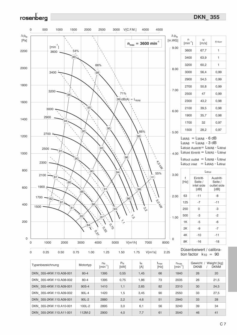
2200
[Pa] [in.WG]
pfa� pfa�
0 500 1000 1500 2000 2500 3000 V[C.F.M.] 4000 4500
2000
1800
1600
1400
1200
1000
800
600
400
200
00
0 0.25 0.50 0.75 1.00 1.25 1.50 1.75 V[m³/s] 2.25
1000 2000 3000 4000 5000 V[m³/h] 7000 80000
1.00
2.00
3.00
4.00
5.00
6.00
7.00
8.00
9.00n = 3600 minmax
-1
[min ]-1
2100
1700
1500
2300
3400
3200
4,0kW
2,2
0,55
0,75
3600
3000
2700
2500
1900
2900
0,37
1,1
1,5
3,0kW
55%
54%
66%
66%
98
99
96
95
94
93
9391
90
90
91
9381
82
84
8182
87
86
86
86
87
94
96
98
101
95
96
99
99 dB(A) = LWA8
71%
Typenbezeichnung MotortypnN
[min-1]PN
[kW]IN[A]
fmax[Hz]
nmax[min-1]
Gewicht / Weight [kg]DKNB / DKNM
DKN_ 355-4KW.110.A08-001 80-4 1395 0,55 1,45 66 1840 26 20
DKN_ 355-4KW.110.A08-002 80-4 1395 0,75 1,86 73 2035 26 21,5
DKN_ 355-4KW.110.A09-001 90S-4 1410 1,1 2,65 82 2310 30 24,5
DKN_ 355-4KW.110.A09-002 90L-4 1420 1,5 3,45 90 2550 33 27,5
DKN_ 355-2KW.110.A09-001 90L-2 2880 2,2 4,6 51 2940 33 28
DKN_ 355-2KW.110.A10-001 100L-2 2895 3,0 6,1 56 3240 39 34
DKN_ 355-2KW.110.A11-001 112M-2 2900 4,0 7,7 61 3540 46 41
DKN_ 355
n[min-1]
u[m/s]
� Korr
3600 67,7 1
3400 63,9 1
3200 60,2 1
3000 56,4 0,99
2900 54,5 0,99
2700 50,8 0,99
2500 47 0,99
2300 43,2 0,98
2100 39,5 0,98
1900 35,7 0,98
1700 32 0,97
1500 28,2 0,97
LWA5 = LWA8 - 6 dBLWA6 = LWA8 - 3 dBLWokt Austritt= LWA8 - LWrelLWokt Eintritt = LWA5 - LWrel
LWoct outlet = LWA8 - LWrelLWoct inlet = LWA5 - LWrel
f[Hz]
LWrel
Eintritt-Seite /
inlet side[dB]
Austritt-Seite /
outlet side[dB]
63 -11 -8
125 -7 -11
250 0 -3
500 -3 -2
1K -5 -6
2K -9 -7
4K -10 -11
8K -16 -18
Düsenbeiwert / calibra-tion factor k10 = 90
C 7

2200
2200
2400
3200
[min ]-1[Pa] [in.WG]
pfa� pfa�
0 1000 2000 3000 4000 5000 6000 V[C.F.M.]
2000
1800
1600
1400
1200
1000
800
600
400
200
00
0 0.50 1.00 1.50 2.00 2.50 3.00 V[m³/s]
2000 4000 6000 8000 10000 V[m³/h]0
1.00
2.00
3.00
4.00
5.00
6.00
7.00
8.00
9.00
5,5KW
n = 3200 minmax
-1
4,0
2,21,5
0,75
0,55
1,1
3,0
3000
2800
2600
2000
1800
1600
1500
1400
1200
58%
67%
66%
71%
57%
97
97
94
94
9591
91
90
94
96
99
92
90
88
83
85
87
8282
7979
80
82
84
87
87
97
100
102
98 dB(A) = LWA8
DKN_ 400
n[min-1]
u[m/s]
� Korr
3200 67,7 1
3000 63,5 1
2800 59,2 1
2600 55 0,99
2400 50,8 0,99
2200 46,5 0,99
2000 42,3 0,99
1800 38,1 0,98
1600 33,8 0,98
1500 31,7 0,98
1400 29,6 0,97
1200 25,4 0,97
LWA5 = LWA8 - 6 dBLWA6 = LWA8 - 3 dBLWokt Austritt= LWA8 - LWrelLWokt Eintritt = LWA5 - LWrel
LWoct outlet = LWA8 - LWrelLWoct inlet = LWA5 - LWrel
f[Hz]
LWrel
Eintritt-Seite /
inlet side[dB]
Austritt-Seite /
outlet side[dB]
63 -11 -9
125 -4 -8
250 0 -2
500 -3 -2
1K -5 -5
2K -8 -8
4K -12 -13
8K -18 -19
Düsenbeiwert / calibra-tion factor k10 = 113
Typenbezeichnung MotortypnN
[min-1]PN
[kW]IN[A]
fmax[Hz]
nmax[min-1]
Gewicht / Weight [kg]DKNB / DKNM
DKN_ 400-4KW.123.A08-001 80-4 1395 0,75 1,86 56 1560 27 22,5
DKN_ 400-4KW.123.A09-001 90S-4 1410 1,1 2,65 64 1800 32 25,5
DKN_ 400-4KW.123.A09-002 90L-4 1420 1,5 3,45 70 1985 35 29
DKN_ 400-4KW.123.A10-001 100L-4 1420 2,2 4,90 79 2240 40 35
DKN_ 400-4KW.123.A10-002 100L-4 1420 3,0 6,40 88 2500 43 38
DKN_ 400-4KW.123.A11-001 112M-4 1440 4,0 8,30 95 2735 50 44
DKN_ 400-2KW.123.A13-001 132S-2 2915 5,5 11,1 52 3030 66 54
DKN_ 400-2KW.123.A13-002 132S-2 2915 7,5 14,7 55 3200 68 62
C 8
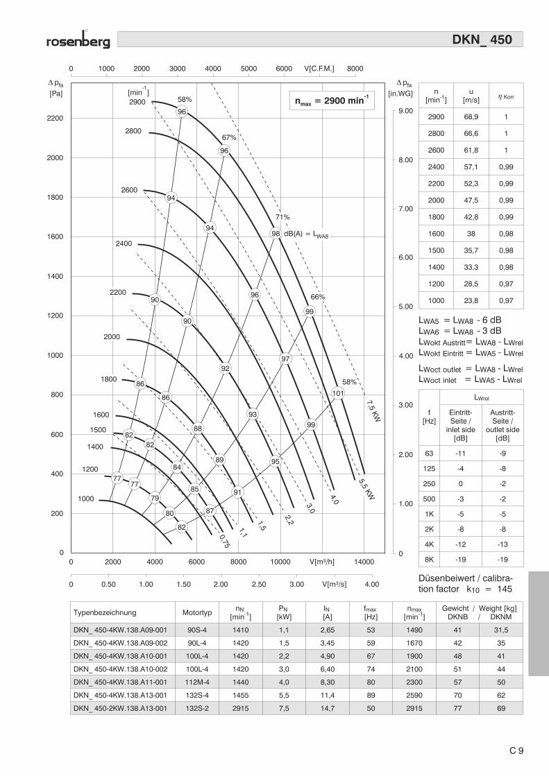
2200
2900 58%
67%2800
2600
2400
[min ]-1
[Pa] [in.WG]
pfa� pfa�
0 1000 2000 3000 4000 5000 6000 V[C.F.M.] 8000
2000
1800
1600
1400
1200
1000
800
600
400
200
00
0 0.50 1.00 1.50 2.00 2.50 3.00 V[m³/s] 4.00
2000 4000 6000 8000 10000 V[m³/h] 140000
1.00
2.00
3.00
4.00
5.00
6.00
7.00
8.00
9.00
7777
79
80
82
82
86
90
90
92
93
95
99
97
99
96
96
94
94
96
10186
88
89
91
82
84
85
87
2200
2000
1800
1600
1400
1500
1200
1000
66%
58%
71%4,0
5,5KW
7,5KW
3,0
2,21,51,10,75
98 dB(A) = LWA8
n = 2900 minmax
-1
Typenbezeichnung MotortypnN
[min-1]PN
[kW]IN[A]
fmax[Hz]
nmax[min-1]
Gewicht / Weight [kg]DKNB / DKNM
DKN_ 450-4KW.138.A09-001 90S-4 1410 1,1 2,65 53 1490 41 31,5
DKN_ 450-4KW.138.A09-002 90L-4 1420 1,5 3,45 59 1670 42 35
DKN_ 450-4KW.138.A10-001 100L-4 1420 2,2 4,90 67 1900 48 41
DKN_ 450-4KW.138.A10-002 100L-4 1420 3,0 6,40 74 2100 51 44
DKN_ 450-4KW.138.A11-001 112M-4 1440 4,0 8,30 80 2300 57 50
DKN_ 450-4KW.138.A13-001 132S-4 1455 5,5 11,4 89 2590 70 62
DKN_ 450-2KW.138.A13-001 132S-2 2915 7,5 14,7 50 2915 77 69
DKN_ 450
n[min-1]
u[m/s]
� Korr
2900 68,9 1
2800 66,6 1
2600 61,8 1
2400 57,1 0,99
2200 52,3 0,99
2000 47,5 0,99
1800 42,8 0,99
1600 38 0,98
1500 35,7 0,98
1400 33,3 0,98
1200 28,5 0,97
1000 23,8 0,97
LWA5 = LWA8 - 6 dBLWA6 = LWA8 - 3 dBLWokt Austritt= LWA8 - LWrelLWokt Eintritt = LWA5 - LWrel
LWoct outlet = LWA8 - LWrelLWoct inlet = LWA5 - LWrel
f[Hz]
LWrel
Eintritt-Seite /
inlet side[dB]
Austritt-Seite /
outlet side[dB]
63 -11 -9
125 -4 -8
250 0 -2
500 -3 -2
1K -5 -5
2K -8 -8
4K -12 -13
8K -19 -19
Düsenbeiwert / calibra-tion factor k10 = 145
C 9
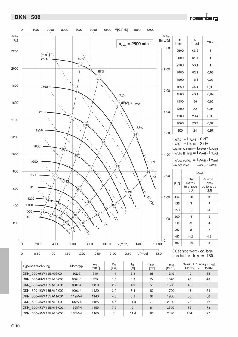
2200
2500 59%
67%
60%
[min ]-1
[Pa] [in.WG]
pfa� pfa�
0 1000 2000 3000 4000 5000 6000 V[C.F.M.] 8000 9000
2000
1800
1600
1400
1200
1000
800
600
400
200
00
0 0.50 1.00 1.50 2.00 2.50 3.00 3.50 V[m³/s] 4.50
2000 4000 6000 8000 10000 V[m³/h] 14000 160000
1.00
2.00
3.00
4.00
5.00
6.00
7.00
8.00
9.00
2100
1500
1350
1200
1000
900
1650
n = 2500 minmax
-1
2300
1950
1800
1100
68%
5,5KW
7,5
3,0
2,2
1,1
4,0
1,5
0,75
94
90
90
92
99
95
93
90
88
84
86
88
83
81
79
7878
7474
76
77
79
8383
92
97
87
87
94
95 dB(A) = LWA8
72%
Typenbezeichnung MotortypnN
[min-1]PN
[kW]IN[A]
fmax[Hz]
nmax[min-1]
Gewicht / Weight [kg]DKNB / DKNM
DKN_ 500-6KW.155.A09-001 90L-6 915 1,1 2,9 68 1245 40 35
DKN_ 500-6KW.155.A10-001 100L-6 925 1,5 3,9 74 1370 45 43
DKN_ 500-4KW.155.A10-001 100L-4 1420 2,2 4,9 55 1560 45 51
DKN_ 500-4KW.155.A10-002 100L-4 1420 3,0 6,4 60 1700 48 54
DKN_ 500-4KW.155.A11-001 112M-4 1440 4,0 8,3 66 1900 55 60
DKN_ 500-4KW.155.A13-001 132S-4 1455 5,5 11,4 73 2120 72 72
DKN_ 500-4KW.155.A13-002 132M-4 1455 7,5 15,1 81 2350 75 78
DKN_ 500-4KW.155.A16-001 160M-4 1460 11 21,4 85 2480 104 97
DKN_ 500
n[min-1]
u[m/s]
� Korr
2500 66,8 1
2300 61,4 1
2100 56,1 1
1950 52,1 0,99
1800 48,1 0,99
1650 44,1 0,99
1500 40,1 0,99
1350 36 0,98
1200 32 0,98
1100 29,4 0,98
1000 26,7 0,97
900 24 0,97
LWA5 = LWA8 - 6 dBLWA6 = LWA8 - 3 dBLWokt Austritt= LWA8 - LWrelLWokt Eintritt = LWA5 - LWrel
LWoct outlet = LWA8 - LWrelLWoct inlet = LWA5 - LWrel
f[Hz]
LWrel
Eintritt-Seite /
inlet side[dB]
Austritt-Seite /
outlet side[dB]
63 -10 -10
125 -3 -7
250 0 -1
500 -4 -3
1K -5 -4
2K -8 -8
4K -12 -13
8K -19 -20
Düsenbeiwert / calibra-tion factor k10 = 180
C 10
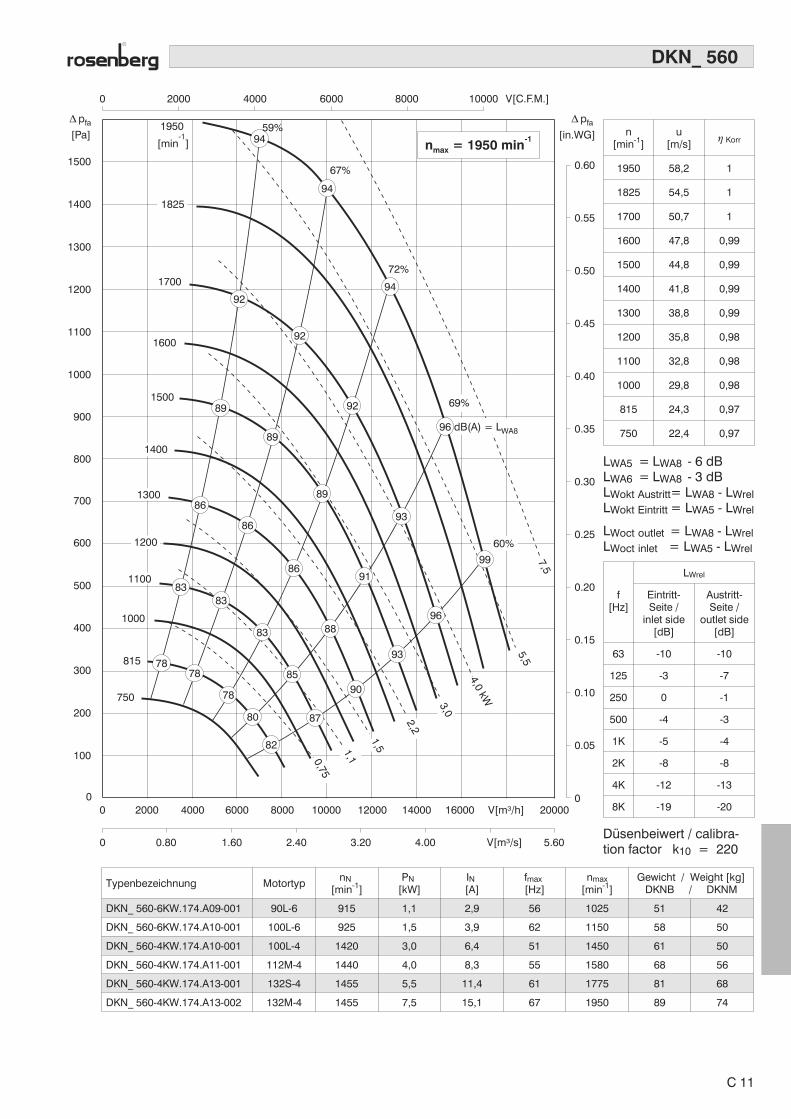
[Pa] [in.WG]
pfa� pfa�
0 2000 4000 6000 V[C.F.M.]100008000
100
200
300
400
500
600
700
800
900
1000
1100
1200
1300
1400
1500
00
0 0.80 1.60 2.40 3.20 4.00 5.60V[m³/s]
2000 4000 6000 8000 10000 12000 V[m³/h]14000 16000 200000
0.05
0.10
0.15
0.20
0.25
0.30
0.35
0.40
0.45
0.50
0.55
0.60
1950
1700
1600
1500
[min ]-1
n = 1950 minmax
-1
4,0kW
5,5
7,5
1400
1300
1200
1000
815
750
1100
1825
1,1
1,5
2,2
3,0
0,75
96 dB(A) = LWA8
9459%
67%
72%
94
92
92
9289
89
89
86
86
86
88
85
87
78
7878
80
82
83
8383
90
91
96
93
93
94
99
69%
60%
Typenbezeichnung MotortypnN
[min-1]PN
[kW]IN[A]
fmax[Hz]
nmax[min-1]
Gewicht / Weight [kg]DKNB / DKNM
DKN_ 560-6KW.174.A09-001 90L-6 915 1,1 2,9 56 1025 51 42
DKN_ 560-6KW.174.A10-001 100L-6 925 1,5 3,9 62 1150 58 50
DKN_ 560-4KW.174.A10-001 100L-4 1420 3,0 6,4 51 1450 61 50
DKN_ 560-4KW.174.A11-001 112M-4 1440 4,0 8,3 55 1580 68 56
DKN_ 560-4KW.174.A13-001 132S-4 1455 5,5 11,4 61 1775 81 68
DKN_ 560-4KW.174.A13-002 132M-4 1455 7,5 15,1 67 1950 89 74
DKN_ 560
n[min-1]
u[m/s]
� Korr
1950 58,2 1
1825 54,5 1
1700 50,7 1
1600 47,8 0,99
1500 44,8 0,99
1400 41,8 0,99
1300 38,8 0,99
1200 35,8 0,98
1100 32,8 0,98
1000 29,8 0,98
815 24,3 0,97
750 22,4 0,97
LWA5 = LWA8 - 6 dBLWA6 = LWA8 - 3 dBLWokt Austritt= LWA8 - LWrelLWokt Eintritt = LWA5 - LWrel
LWoct outlet = LWA8 - LWrelLWoct inlet = LWA5 - LWrel
f[Hz]
LWrel
Eintritt-Seite /
inlet side[dB]
Austritt-Seite /
outlet side[dB]
63 -10 -10
125 -3 -7
250 0 -1
500 -4 -3
1K -5 -4
2K -8 -8
4K -12 -13
8K -19 -20
Düsenbeiwert / calibra-tion factor k10 = 220
C 11
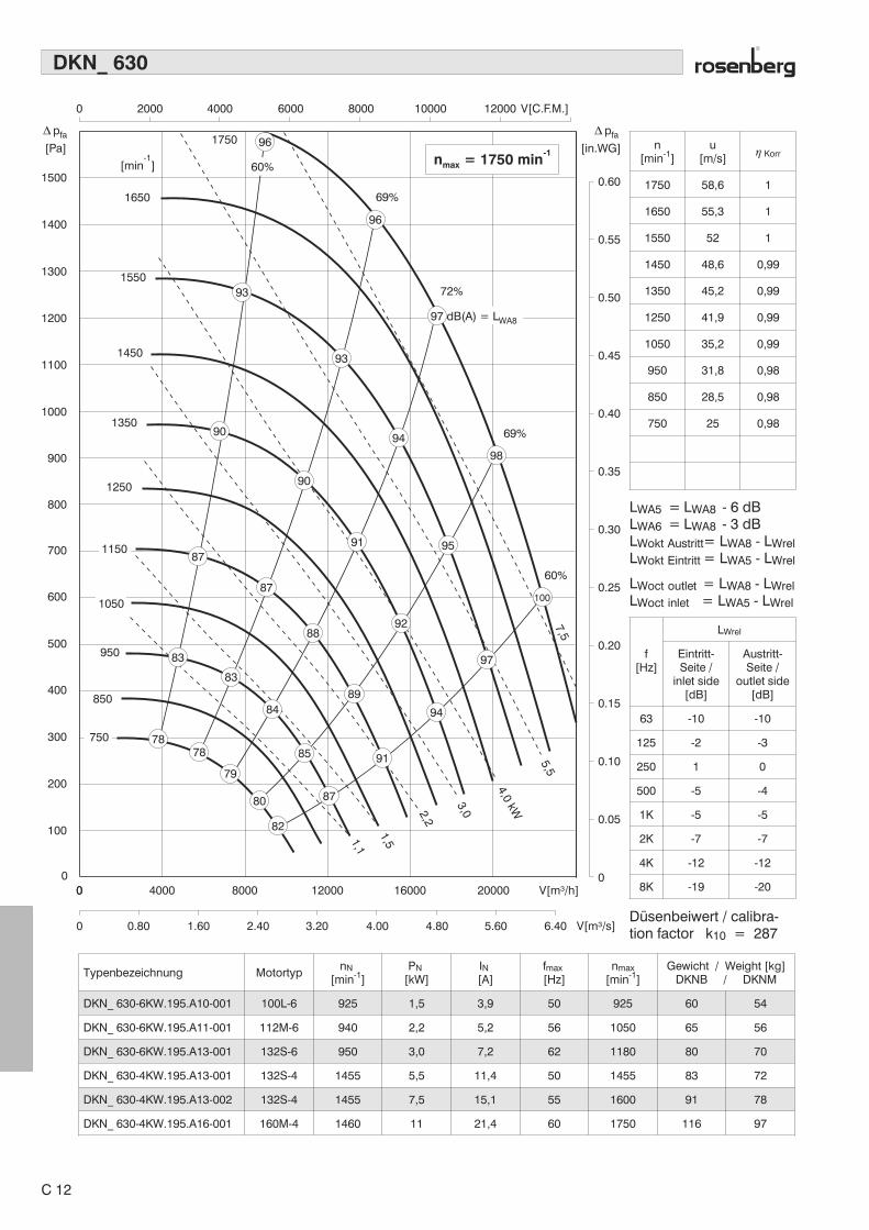
[Pa] [in.WG]
pfa� pfa�
100
200
300
400
500
600
700
800
900
1000
1100
1200
1300
1400
1500
0 0
0.05
0.10
0.15
0.20
0.25
0.30
0.35
0.40
0.45
0.50
0.55
0.6069%
1750
1650
1550
1450
1350
1250
[min ]-1
4,0kW
5,57,5
1,1
1,5
2,2
3,0
00
0 0.80 1.60 2.40 3.20 4.00 4.80 5.60 6.40 V[m³/s]
4000 8000 12000 16000 20000 V[m³/h]
0 2000 4000 6000 8000 10000 12000 V[C.F.M.]
n = 1750 minmax
-1
950
850
750
1050
1150
97 dB(A) = LWA8
98
96
93
93
90
90
91
92
94
88
87
87
83
83
84
85
87
7878
79
80
82
89
91
95
97
94
96
69%
72%
60%
100
60%
Typenbezeichnung MotortypnN
[min-1]PN
[kW]IN[A]
fmax[Hz]
nmax[min-1]
Gewicht / Weight [kg]DKNB / DKNM
DKN_ 630-6KW.195.A10-001 100L-6 925 1,5 3,9 50 925 60 54
DKN_ 630-6KW.195.A11-001 112M-6 940 2,2 5,2 56 1050 65 56
DKN_ 630-6KW.195.A13-001 132S-6 950 3,0 7,2 62 1180 80 70
DKN_ 630-4KW.195.A13-001 132S-4 1455 5,5 11,4 50 1455 83 72
DKN_ 630-4KW.195.A13-002 132S-4 1455 7,5 15,1 55 1600 91 78
DKN_ 630-4KW.195.A16-001 160M-4 1460 11 21,4 60 1750 116 97
DKN_ 630
n[min-1]
u[m/s]
� Korr
1750 58,6 1
1650 55,3 1
1550 52 1
1450 48,6 0,99
1350 45,2 0,99
1250 41,9 0,99
1050 35,2 0,99
950 31,8 0,98
850 28,5 0,98
750 25 0,98
LWA5 = LWA8 - 6 dBLWA6 = LWA8 - 3 dBLWokt Austritt= LWA8 - LWrelLWokt Eintritt = LWA5 - LWrel
LWoct outlet = LWA8 - LWrelLWoct inlet = LWA5 - LWrel
f[Hz]
LWrel
Eintritt-Seite /
inlet side[dB]
Austritt-Seite /
outlet side[dB]
63 -10 -10
125 -2 -3
250 1 0
500 -5 -4
1K -5 -5
2K -7 -7
4K -12 -12
8K -19 -20
Düsenbeiwert / calibra-tion factor k10 = 287
C 12

[Pa] [in.WG]
pfa� pfa�
100
200
300
400
500
600
600
700
700
800
800
900
1000
1100
1200
1200
1300
1300
1400
1500
[min ]-1
0 0
0.05
0.10
0.15
0.20
0.25
0.30
0.35
0.40
0.45
0.50
0.55
0.60
0 2000 4000 6000 8000 10000 12000 V[C.F.M.] 16000 18000
0
0 1.00 2.00 3.00 4.00 5.00 6.00 7.00 V[m³/s] 9.00
4000 8000 12000 16000 20000 V[m³/h] 28000 32000
11
1,50,75
n = 1500 minmax
-1
5,5kW
7,5
2,2
3,0
4,0
1400
1500
1000
1100
900
1,1
96 dB(A) = LWA8
97
60%
69%
94
93
93
95
97
93
89
90
89
9185
85
86
87
85
8079
79
81
83
98
69%
60%
100
96
73%
Typenbezeichnung MotortypnN
[min-1]PN
[kW]IN[A]
fmax[Hz]
nmax[min-1]
Gewicht / Weight [kg]DKNB / DKNM
DKN_ 710-8KW.219.A11-001 112M-8 705 1,5 3,9 54 760 138 -
DKN_ 710-8KW.219.A13-001 132S-8 700 2,2 5,7 62 870 155 -
DKN_ 710-6KW.219.A13-001 132S-6 950 3,0 7,2 51 970 155 -
DKN_ 710-6KW.219.A13-002 132M-6 950 4,0 9,4 56 1060 160 -
DKN_ 710-6KW.219.A13-003 132M-6 950 5,5 12,8 62 1180 168 -
DKN_ 710-6KW.219.A16-001 160M-6 960 7,5 17,0 68 1305 190 -
DKN_ 710-4KW.219.A16-001 160M-4 1460 11 21,4 51 1500 182 -
DKN_ 710
n[min-1]
u[m/s]
� Korr
1500 56,4 1
1400 52,6 1
1300 48,9 1
1200 45,1 0,99
1100 41,4 0,99
1000 37,6 0,99
900 33,8 0,99
800 30,1 0,98
700 26,3 0,98
600 22,6 0,98
LWA5 = LWA8 - 6 dBLWA6 = LWA8 - 3 dBLWokt Austritt= LWA8 - LWrelLWokt Eintritt = LWA5 - LWrel
LWoct outlet = LWA8 - LWrelLWoct inlet = LWA5 - LWrel
f[Hz]
LWrel
Eintritt-Seite /
inlet side[dB]
Austritt-Seite /
outlet side[dB]
63 -3 -2
125 1 0
250 -4 -4
500 -5 -5
1K -2 -2
2K -11 -11
4K -17 -17
8K -24 -25
Düsenbeiwert / calibra-tion factor k10 = 370
C 13
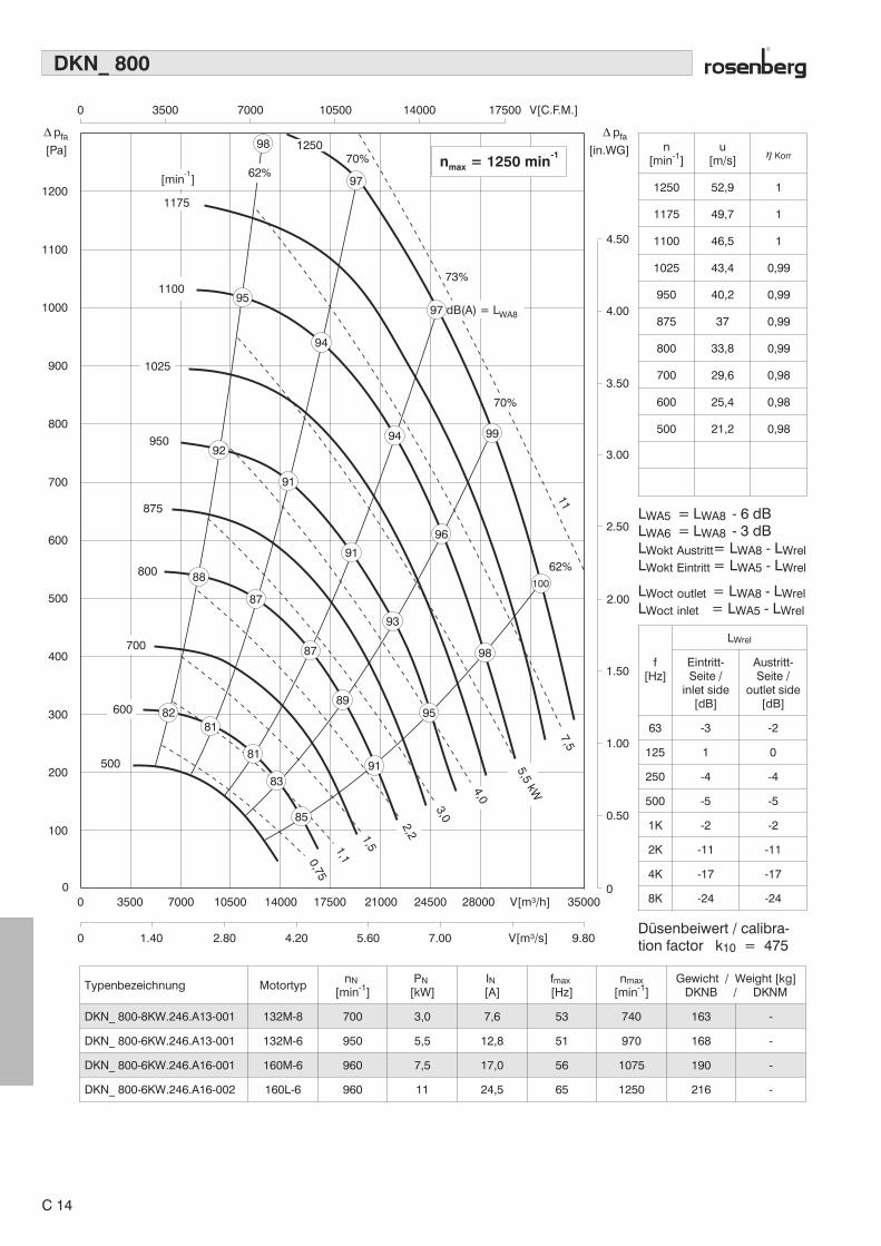
[Pa] [in.WG]
pfa� pfa�
0 3500 7000 10500 V[C.F.M.]1750014000
00
0 1.40 2.80 4.20 5.60 7.00 9.80V[m³/s]
3500 7000 10500 14000 17500 21000 V[m³/h]24500 28000 350000
1100
1200
1000
900
800
950
700
875
800
600
500
400
300
200500
1000.50
1.00
1.50
2.00
2.50
3.00
3.50
4.00
4.50
11
1,5
n = 1250 minmax
-1
7,5
3,0
1,10,75
5,5kW
2,2
4,0
[min ]-1
1100
1175
1025
700
600
97 dB(A) = LWA8
97
95
94
94
96
98
95
100
91
93
87
87
88
8281
81
83
85
91
89
91
9299
70%
73%
98
62%
1250
70%
62%
Typenbezeichnung MotortypnN
[min-1]PN
[kW]IN[A]
fmax[Hz]
nmax[min-1]
Gewicht / Weight [kg]DKNB / DKNM
DKN_ 800-8KW.246.A13-001 132M-8 700 3,0 7,6 53 740 163 -
DKN_ 800-6KW.246.A13-001 132M-6 950 5,5 12,8 51 970 168 -
DKN_ 800-6KW.246.A16-001 160M-6 960 7,5 17,0 56 1075 190 -
DKN_ 800-6KW.246.A16-002 160L-6 960 11 24,5 65 1250 216 -
DKN_ 800
n[min-1]
u[m/s]
� Korr
1250 52,9 1
1175 49,7 1
1100 46,5 1
1025 43,4 0,99
950 40,2 0,99
875 37 0,99
800 33,8 0,99
700 29,6 0,98
600 25,4 0,98
500 21,2 0,98
LWA5 = LWA8 - 6 dBLWA6 = LWA8 - 3 dBLWokt Austritt= LWA8 - LWrelLWokt Eintritt = LWA5 - LWrel
LWoct outlet = LWA8 - LWrelLWoct inlet = LWA5 - LWrel
f[Hz]
LWrel
Eintritt-Seite /
inlet side[dB]
Austritt-Seite /
outlet side[dB]
63 -3 -2
125 1 0
250 -4 -4
500 -5 -5
1K -2 -2
2K -11 -11
4K -17 -17
8K -24 -24
Düsenbeiwert / calibra-tion factor k10 = 475
C 14
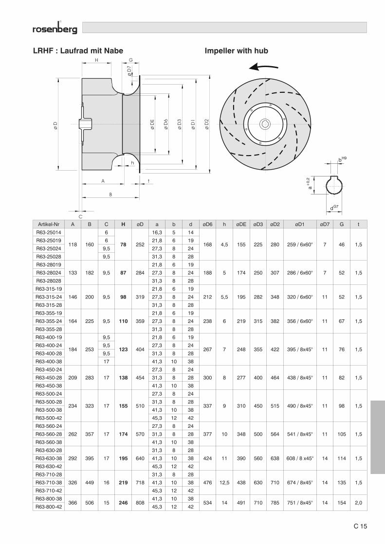
LRHF : Laufrad mit Nabe Impeller with hub
Artikel-Nr A B C H øD a b d øD6 h øDE øD3 øD2 øD1 øD7 G t
R63-25014
118 160
6
78 252
16,3 5 14
168 4,5 155 225 280 259 / 6x60° 7 46 1,5R63-25019 6 21,8 6 19
R63-25024 9,5 27,3 8 24
R63-25028 9,5 31,3 8 28
R63-28019
133 182 9,5 87 284
21,8 6 19
188 5 174 250 307 286 / 6x60° 7 52 1,5R63-28024 27,3 8 24
R63-28028 31,3 8 28
R63-315-19
146 200 9,5 98 319
21,8 6 19
212 5,5 195 282 348 320 / 6x60° 11 52 1,5R63-315-24 27,3 8 24
R63-315-28 31,3 8 28
R63-355-19
164 225 9,5 110 359
21,8 6 19
238 6 219 315 382 356 / 6x60° 11 67 1,5R63-355-24 27,3 8 24
R63-355-28 31,3 8 28
R63-400-19
184 253
9,5
123 404
21,8 6 19
267 7 248 355 422 395 / 8x45° 11 76 1,5R63-400-24 9,5 27,3 8 24
R63-400-28 9,5 31,3 8 28
R63-400-38 17 41,3 10 38
R63-450-24
209 283 17 138 454
27,3 8 24
300 8 277 400 464 438 / 8x45° 11 82 1,5R63-450-28 31,3 8 28
R63-450-38 41,3 10 38
R63-500-24
234 323 17 155 510
27,3 8 24
337 9 310 450 515 490 / 8x45° 11 98 1,5R63-500-28 31,3 8 28
R63-500-38 41,3 10 38
R63-500-42 45,3 12 42
R63-560-24
262 357 17 174 570
27,3 8 24
377 10 348 500 564 541 / 8x45° 11 105 1,5R63-560-28 31,3 8 28
R63-560-38 41,3 10 38
R63-630-28
292 395 17 195 640
31,3 8 28
424 11 390 560 638 608 / 8 x45° 14 114 1,5R63-630-38 41,3 10 38
R63-630-42 45,3 12 42
R63-710-28
326 449 16 219 718
31,3 8 28
476 12,5 438 630 710 674 / 8x45° 14 135 1,5R63-710-38 41,3 10 38
R63-710-42 45,3 12 42
R63-800-38366 506 15 246 808
41,3 10 38534 14 491 710 785 751 / 8x45° 14 154 2,0
R63-800-42 45,3 12 42
bH9
dG7
a+
0,2
C 15
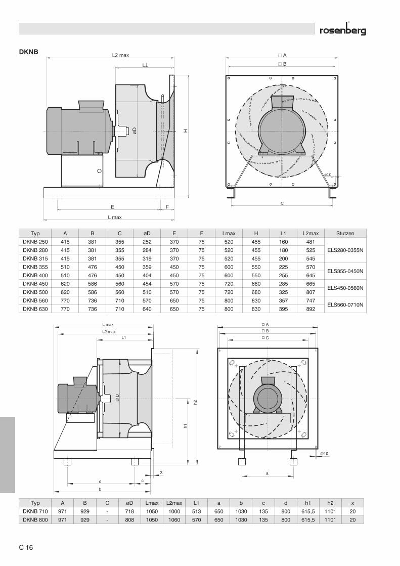
DKNB
Typ A B C øD E F Lmax H L1 L2max Stutzen
DKNB 250 415 381 355 252 370 75 520 455 160 481
ELS280-0355NDKNB 280 415 381 355 284 370 75 520 455 180 525
DKNB 315 415 381 355 319 370 75 520 455 200 545
DKNB 355 510 476 450 359 450 75 600 550 225 570ELS355-0450N
DKNB 400 510 476 450 404 450 75 600 550 255 645
DKNB 450 620 586 560 454 570 75 720 680 285 665ELS450-0560N
DKNB 500 620 586 560 510 570 75 720 680 325 807
DKNB 560 770 736 710 570 650 75 800 830 357 747ELS560-0710N
DKNB 630 770 736 710 640 650 75 800 830 395 892
AL2 max
L max
L1
EC
ø10
F
HøD
B
Typ A B C øD Lmax L2max L1 a b c d h1 h2 x
DKNB 710 971 929 - 718 1050 1000 513 650 1030 135 800 615,5 1101 20
DKNB 800 971 929 - 808 1050 1060 570 650 1030 135 800 615,5 1101 20
∅10
A
B
C
X a
L max
L2 max
L1
d
b
c
∅D
h1
h2
C 16

DKNM
∅ d
A
B
C
L2 max
L1
∅D
øD
øD
øD
E 21
Typ A B C d D L2max L1 DE D1 D2
DKNM 280 500 450 320 11 284 555 210 174 286 307
DKNM 315 500 450 360 11 319 575 230 195 320 348
DKNM 355 500 450 395 11 359 600 255 219 356 382
DKNM 400 500 450 420 11 404 710 287 248 395 422
DKNM 450 630 580 470 14 454 745 322 277 438 464
DKNM 500 630 580 535 14 510 840 356 310 487 515
DKNM 560 800 750 585 14 570 820 396 348 541 564
DKNM 630 800 750 625 14 640 920 436 390 608 638
Andere Abmessungen auf Anfrage.Other dimensions on request.
C 17
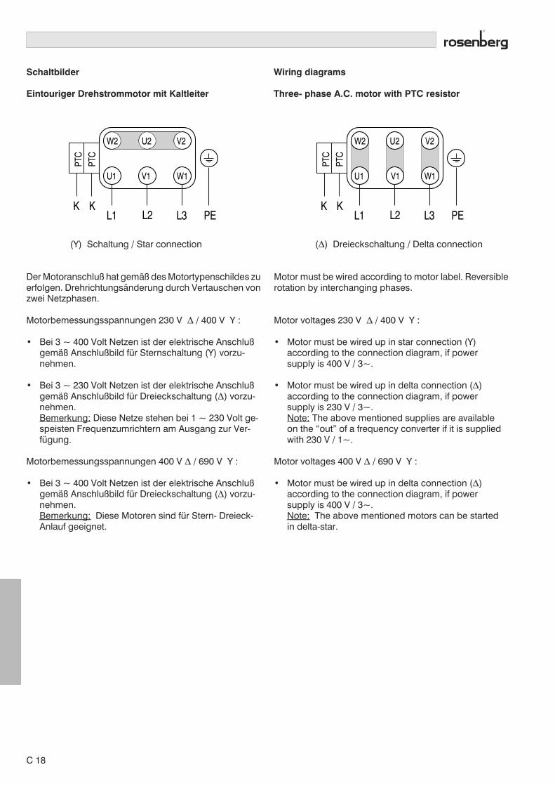
Schaltbilder
Eintouriger Drehstrommotor mit Kaltleiter
Wiring diagrams
Three- phase A.C. motor with PTC resistor
L1 L2 L3
W2
U1
U2
V1
V2
W1
PTC
PTC
K KPE L1 L2 L3
W2 U2 V2
U1 V1 W1
PTC
PTC
K KPE
(Y) Schaltung / Star connection
Der Motoranschluß hat gemäß des Motortypenschildes zuerfolgen. Drehrichtungsänderung durch Vertauschen vonzwei Netzphasen.
Motorbemessungsspannungen 230 V � / 400 V Y :
• Bei 3 ~ 400 Volt Netzen ist der elektrische Anschlußgemäß Anschlußbild für Sternschaltung (Y) vorzu-nehmen.
• Bei 3 ~ 230 Volt Netzen ist der elektrische Anschlußgemäß Anschlußbild für Dreieckschaltung (�) vorzu-nehmen.Bemerkung: Diese Netze stehen bei 1 ~ 230 Volt ge-speisten Frequenzumrichtern am Ausgang zur Ver-fügung.
Motorbemessungsspannungen 400 V � / 690 V Y :
• Bei 3 ~ 400 Volt Netzen ist der elektrische Anschlußgemäß Anschlußbild für Dreieckschaltung (�) vorzu-nehmen.Bemerkung: Diese Motoren sind für Stern- Dreieck-Anlauf geeignet.
(�) Dreieckschaltung / Delta connection
Motor must be wired according to motor label. Reversiblerotation by interchanging phases.
Motor voltages 230 V � / 400 V Y :
• Motor must be wired up in star connection (Y)according to the connection diagram, if powersupply is 400 V / 3~.
• Motor must be wired up in delta connection (�)according to the connection diagram, if powersupply is 230 V / 3~.Note: The above mentioned supplies are availableon the “out” of a frequency converter if it is suppliedwith 230 V / 1~.
Motor voltages 400 V � / 690 V Y :
• Motor must be wired up in delta connection (�)according to the connection diagram, if powersupply is 400 V / 3~.Note: The above mentioned motors can be startedin delta-star.
C 18
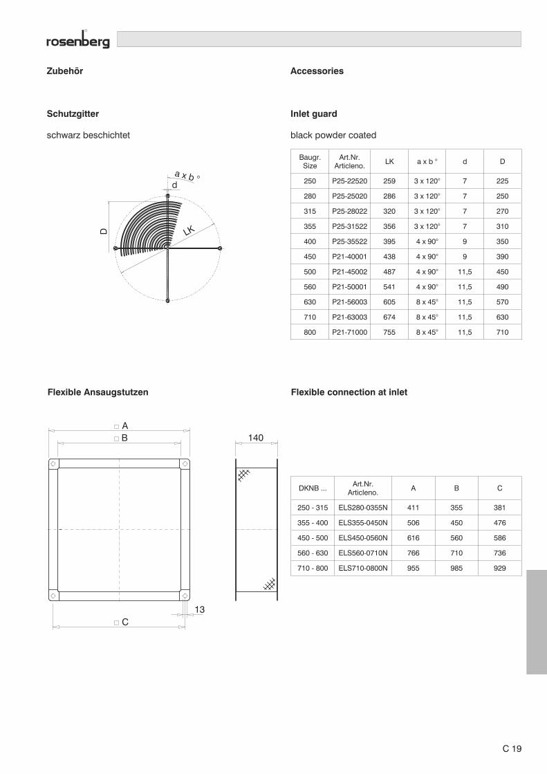
Zubehör
Schutzgitter
schwarz beschichtet
Accessories
Inlet guard
black powder coated
da x b °
LKD
Baugr.Size
Art.Nr.Articleno.
LK a x b ° d D
250 P25-22520 259 3 x 120° 7 225
280 P25-25020 286 3 x 120° 7 250
315 P25-28022 320 3 x 120° 7 270
355 P25-31522 356 3 x 120° 7 310
400 P25-35522 395 4 x 90° 9 350
450 P21-40001 438 4 x 90° 9 390
500 P21-45002 487 4 x 90° 11,5 450
560 P21-50001 541 4 x 90° 11,5 490
630 P21-56003 605 8 x 45° 11,5 570
710 P21-63003 674 8 x 45° 11,5 630
800 P21-71000 755 8 x 45° 11,5 710
Flexible Ansaugstutzen
AB 140
13C
Flexible connection at inlet
DKNB ...Art.Nr.
Articleno.A B C
250 - 315 ELS280-0355N 411 355 381
355 - 400 ELS355-0450N 506 450 476
450 - 500 ELS450-0560N 616 560 586
560 - 630 ELS560-0710N 766 710 736
710 - 800 ELS710-0800N 955 985 929
C 19

Zubehör
Gummischwingungsdämpfer
Accessories
Rubber damper
DH
d (beidseitig)
TypType
Art.Nr.Articleno.
D H d
30 x 20 x M8 GDS000-0021N 30 20 M 8
30 x 30 x M8 GDS000-0022N 30 30 M 8
50 x 40 x M10 GDS000-0051N 50 40 M10
50 x 50 x M10 GDS000-0052N 50 50 M10
Federdämpfer Typ 2 Spring suspension type 2
ø70
106
M10
11
120150
95 17
Typ / Type Art.Nr. / Articleno.
SP 775 - 01 FDS000-0001N
SP 775 - 02 FDS000-0002N
SP 775 - 03 FDS000-0003N
SP 775 - 04 FDS000-0004N
SP 775 - 05 FDS000-0005N
SP 775 - 06 FDS000-0006N
SP 775 - 07 FDS000-0007N
SP 775 - 08 FDS000-0008N
Federdämpfer Typ 1 Spring suspension type 1
ø45
60
M8 (beidseitig)
Typ / Type Art.Nr. / Articleno.
SP 770 - 01 FDS000-0011N
SP 770 - 02 FDS000-0012N
SP 770 - 03 FDS000-0013N
SP 770 - 04 FDS000-0014N
SP 770 - 05 FDS000-0015N
SP 770 - 06 FDS000-0016N
SP 770 - 07 FDS000-0017N
C 20

Ausschreibungstext
Rosenberg Radialventilatoren mit freilaufendem LaufradTypenreihe DKNB / DKNM
Radialventilator mit rückwärtsgekrümmtem Hochleistungslaufrad aus seewasser-beständigem Aluminium. Optimiert für Verwendung ohne Spiralgehäuse, mit An-baumotor, horizontal und vertikal einsetzbar.Standardmäßig mit Volumenstrom-Meßeinrichtung ausgerüstet.
Ausführung DKNBMotorlaufrad mit strömungsoptimierter Einströmdüse, Trageinheit, Motorblock undGrundrahmen als Ventilatormodul gefertigt und justiert. Antriebsmotor IMB3.
Ausführung DKNMMotorlaufrad mit strömungsoptimierter Einströmdüse und Trageinheit als Ventilator-modul gefertigt und justiert. Antriebsmotor IMB5.
Laufrad zusammen mit Laufradnabe aus Aluminium-Druckguß entsprechend Güte-stufe G 2.5 nach DIN/ISO 1940 auf 2 Ebenen ausgewuchtet.
DokumentationHerstellererklärung und Betriebsanleitung entsprechend der Maschinenrichtlinie98/37/EWG, CE Kennzeichnung entsprechend der EMV Richtlinie 89/336/EWG undder Niederspannungsrichtlinie 73/23/EWG.
Radialventilator wie vor beschrieben:
Volumenstrom V m³/hDruckerhöhung �pfa PaNennspannung UN VFrequenz f HzMotor-Nennleistung PN kWMotor-Nennstrom IN AMotor-Nenndrehzahl nN min-1
Betriebsfrequenz f HzBetriebsdrehzahl n min-1
Schalleistungspegel LWA dB(A)Fördermitteltemperatur tR °CAbmessungen L x B x H mmGewicht m kg
Ausführung � DKNB � DKNM
Fabrikat : Rosenberg Type
Zubehör� Federschwingungsdämpfer� Frequenzumrichter� Funkentstörfilter� Ansaugstutzen� Ansauggitter
Projekt :
Anlage : Seite:
Pos. Anzahl EinzelpreisBeschreibung
C 21
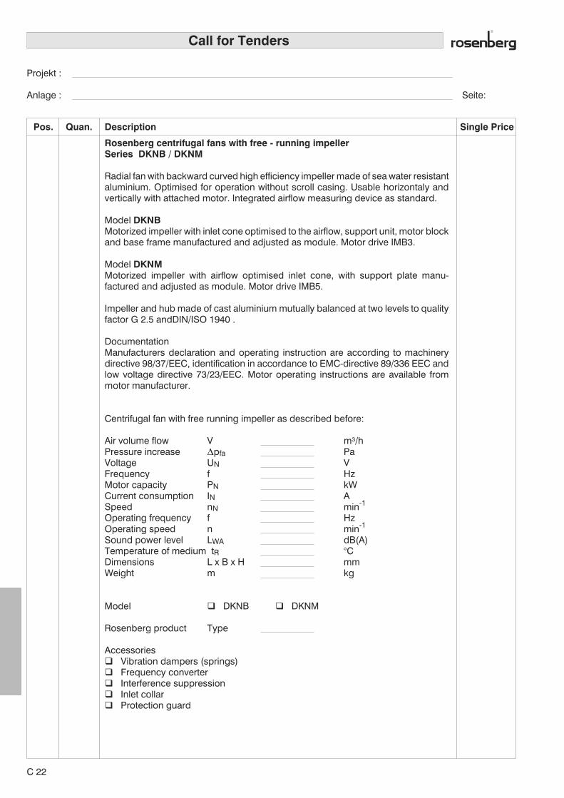
Call for Tenders
Rosenberg centrifugal fans with free - running impellerSeries DKNB / DKNM
Radial fan with backward curved high efficiency impeller made of sea water resistantaluminium. Optimised for operation without scroll casing. Usable horizontaly andvertically with attached motor. Integrated airflow measuring device as standard.
Model DKNBMotorized impeller with inlet cone optimised to the airflow, support unit, motor blockand base frame manufactured and adjusted as module. Motor drive IMB3.
Model DKNMMotorized impeller with airflow optimised inlet cone, with support plate manu-factured and adjusted as module. Motor drive IMB5.
Impeller and hub made of cast aluminium mutually balanced at two levels to qualityfactor G 2.5 andDIN/ISO 1940 .
DocumentationManufacturers declaration and operating instruction are according to machinerydirective 98/37/EEC, identification in accordance to EMC-directive 89/336 EEC andlow voltage directive 73/23/EEC. Motor operating instructions are available frommotor manufacturer.
Centrifugal fan with free running impeller as described before:
Air volume flow V m³/hPressure increase �pfa PaVoltage UN VFrequency f HzMotor capacity PN kWCurrent consumption IN ASpeed nN min-1
Operating frequency f HzOperating speed n min-1
Sound power level LWA dB(A)Temperature of medium tR °CDimensions L x B x H mmWeight m kg
Model � DKNB � DKNM
Rosenberg product Type
Accessories� Vibration dampers (springs)� Frequency converter� Interference suppression� Inlet collar� Protection guard
Projekt :
Anlage : Seite:
Pos. Quan. Single PriceDescription
C 22