R INSTRUCTIONAL MANUAL - Kreg Tool€¦ · · 2014-05-27FOREMAN R INSTRUCTIONAL MANUAL DB55...
20
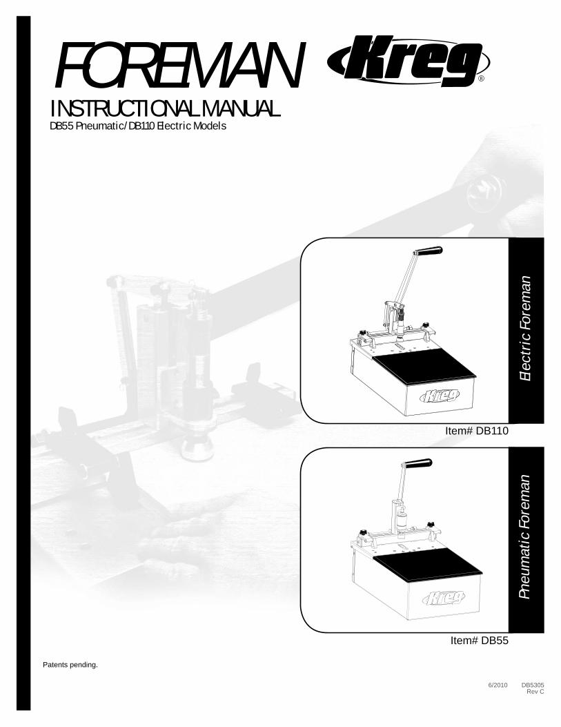
R FOREMAN INSTRUCTIONAL MANUAL DB55 Pneumatic/DB110 Electric Models Electric Foreman Item# DB110 Item# DB55 Pneumatic Foreman Patents pending. 6/2010 DB5305 Rev C
Transcript of R INSTRUCTIONAL MANUAL - Kreg Tool€¦ · · 2014-05-27FOREMAN R INSTRUCTIONAL MANUAL DB55...
R
RFOREMANINSTRUCTIONAL MANUALDB55 Pneumatic/DB110 Electric Models
Elec
tric
For
eman
Item# DB110
Item# DB55
Pneu
mat
ic F
orem
an
Patents pending.
6/2010 DB5305Rev C
R
Congratulations on choosing a Kreg Foreman Semi-Automatic Pocket-Hole Machine! Be sure to read the instructions and the safety warnings completely before using this machine.
Table of Contents
TABLE OF CONTENTS 1SAFETY GUIDELINES 2-6ASSEMBLY INSTRUCTIONS - DB110 7ASSEMBLY INSTRUCTIONS - DB55 8DB110 (Electric Model) 9-12 General Operations/Maintenance 9 Adjusting the EZ DB Fence 10 Adjusting the Drill Bit Depth Stop/Clamping Pad Height 11 Swing Stops/Changing the Drill Bit 12 DB55 (Pneumatic Model) 13-16 General Operations/Maintenance 13 Adjusting the EZ DB Fence 14 Adjusting the Drill Bit Depth Stop/Clamping Cylinder Height/Automatic Lubricator 15 Swing Stops/Changing the Drill Bit 16 Warranty 17Notes 18
Attention:As with all machinery, there are certain hazards involved with operation and use of the machine. Using the machine with respect and caution will considerably lessen the possibility of personal injury. However, if normal safety precautions are overlooked or ignored, personal injury to the operator may result.
This machine was designed for specifi c applications only. Kreg strongly recommends that this machine NOT be modifi ed and/or used for any application other than for which it was designed. If you have any questions relative to its application, DO NOT use the Machine until you have written Kreg Tool and we have advised you.
Table of Contents1.
PIndicates the PHASE (HOT) wire from the powersource
NIndicates the NEUTRAL
wire from the powersource
!Caution,
refer to manualEarth GroundConnection
Make sure all power sources have been disconnectedfrom this machine before opening the electrical box.
Symbols:
R
2.Safety Guidelines
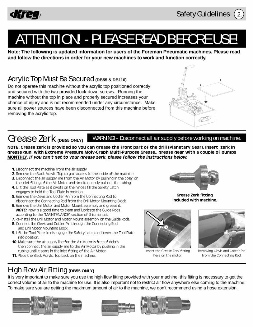
Do not operate this machine without the acrylic top positioned correctly and secured with the two provided lock-down screws. Running the machine without the top in place and properly secured increases your chance of injury and is not recommended under any circumstance. Make sure all power sources have been disconnected from this machine before removing the acrylic top.
ATTENTION! - PLEASE READ BEFORE USE!Note: The following is updated information for users of the Foreman Pneumatic machines. Please read and follow the directions in order for your new machines to work and function correctly.
Grease Zerk (DB55 ONLY)NOTE: Grease zerk is provided so you can grease the front part of the drill (Planetary Gear). Insert zerk in grease gun, with Extreme Pressure Moly-Graph Multi-Purpose Grease., grease gear with a couple of pumps MONTHLY. If you can’t get to your grease zerk, please follow the instructions below.
Grease Zerk fi ttingincluded with machine.
Insert the Grease Zerk fitting here on the motor.
Removing Clevis and Cotter Pin from the Connecting Rod.
High Flow Air Fitting (DB55 ONLY)It is very important to make sure you use the high fl ow fi tting provided with your machine, this fi tting is necessary to get the correct volume of air to the machine for use. It is also important not to restrict air fl ow anywhere else coming to the machine. To make sure you are getting the maximum amount of air to the machine, we don’t recommend using a hose extension.
1. Disconnect the machine from the air supply. 2. Remove the Black Acrylic Top to gain access to the inside of the machine. 3. Disconnect the air supply line from the Air Motor by pushing in the collar on the inlet fitting of the Air Motor and simultaneously pull out the tubing. 4. Lift the Tool Plate as it pivots on the hinges till the Safety Latch engages to hold the Tool Plate in position. 5. Remove the Clevis and Cotter Pin from the Connecting Rod to disconnect the Connecting Rod from the Drill Motor Mounting Block. 6. Remove the Drill Motor and Motor Mount assembly and grease it. NOTE: Now is a good time to clean and lubricate the Guide Rods according to the “MAINTENANCE” section of this manual. 7. Re-install the Drill Motor and Motor Mount assembly on the Guide Rods. 8. Connect the Clevis and Cotter Pin through the Connecting Rod and Drill Motor Mounting Block. 9. Lift the Tool Plate to disengage the Safety Latch and lower the Tool Plate into position. 10. Make sure the air supply line for the Air Motor is free of debris then connect the air supply line to the Air Motor by pushing in the tubing until it seats in the inlet fitting of the Air Motor. 11. Place the Black Acrylic Top back on the machine.
WARNING! - Disconnect all air supply before working on machine.
Acrylic Top Must Be Secured (DB55 & DB110)

R
• Do not operate this machine without the acrylic top securely fastened into place using the provided lock-down screws. Doing so will ncrease your chances of injury or death.
• Woodworking machines are dangerous, and can cause personal injury if not used properly.
• Read safety instructions and operating instructions for your machine completely, before using products. Using this system before understanding its safe and proper use could result in serious injury to the operator.
• Failure to follow these rules may result in serious personal injury.
• For your own safety, read the instruction manual before operating the tool. Learn the tool’s application and limitations as well as the specifi c hazards distinctive to it.
• Keep all guards and safety devices in proper place while using these products.
• Always wear safety glasses.
• Keep hands well away from the pneumatic clamp and rotating bit when operating the machine.
• Avoid awkward hand positions, where a sudden slip could cause contact with the rotating bit. Never reach under the pneumatic clamp pad with either hand to hold down the workpiece.
• As with all machinery, there are certain hazards involved with the operation and use of the machine. Using the machine with respect and caution will considerably lessen the possibility of personal injury. However, if normal safety precautions are overlooked or ignored, personal injury to the operator may result.
• This system was designed for certain applications only. Kreg strongly recommends that this system NOT be modifi ed and/or used for any application other than for which it was designed. If you have any questions relative to its application, DO NOT use the machine until you have written, phoned, or e-mailed Kreg Tool and have been advised accordingly.
• Be aware of kickbacks. Kickbacks occur when the workpiece binds-up while being drilled, causing it to twist, jump, and possibly become airborne. To avoid kickbacks (and potential injury) always use sharp drill bits, keep the machine aligned and maintained properly, and adequately secure/support the workpiece.
• Turn machine off before adjusting. Never adjust the fence, swing stop, clamping cylinder, depth stop, drill bit, or any other part of the machine while it is running.
• Wait for the machine to stop. Make sure the drill comes to a complete stop before adjusting the workpiece or workpiece-angle.
• Ground electric machines. If your machine is equipped with a three-prong plug, it should be plugged into a three-hole electrical receptacle only. If the proper outlet is not available, have one installed by a qualifi ed electrician before use. Never remove the third prong, and never modify the provided plug in any way.
• Remove adjusting keys and wrenches. Be sure to check that all adjusting keys and wrenches are removed from the machine before turning it on.
• Don’t operate in a dangerous or unclean environment. Don’t use power tools in damp or wet locations, or expose them to rain. Keep work area well-lit, un-cluttered, and clean.
• Keep children and visitors away. All children and visitors should be kept a safe distance from the work area, and should not operate the machine under any condition.
• Make your workshop “child-proof”. Use padlocks, master switches, or any other means necessary to make your work area safe for children.
• Use the right tool. Never ‘force’ the tool to do work for which it was not intended. If used properly, the tool will produce better results in less time, under safer conditions.
• Wear proper apparel. No loose clothing, gloves, neckties, rings, bracelets, or any other jewelry that could possibly get caught in moving parts. Non-slip footwear is highly recommended, as is protective hair covering. Remember to always use safety glasses, specifi cally designed as safety wear.
Warnings:
Safety Guidelines3.
R
Safety Guidelines
• Secure the workpiece. Use clamps or a vise to hold work when it is practical and safe. Using the proper tool may allow you to free both hands for tool operation. Also, be sure to never overreach.
• Secure your tools. In the event of the machine tipping or sliding, it is always recommended to secure your tools to the machine, or in another safe location, during use.
• Keep the proper footing and balance. Ensure that you are in no danger of slipping or sliding once you turn the machine on. Once again, non-slip footwear is highly recommended.
• Maintain tools in top condition. Keep tools sharp, clean, and properly maintained for the highest quality and safest performance. Remember to properly follow all lubrication and accessory maintenance practices, as detailed in this Instruction Manual.
• Disconnect tool before servicing. When changing accessories such as bits, clamps, etc., making any sort of physical assessment of the tool, or when motor is being mounted/connected, remember to disconnect the machine from its power source. This will reduce the possibility of accidentally engaging the machine.
• Use recommended accessories only. Use of any additional accessories (add-ons) is strictly at your own risk. This machine was designed with only the use of Kreg certifi ed parts in mind. Use of uncertifi ed accessories may be hazardous.
• Avoid accidental starting. Make sure power switch is positioned at “OFF” and that no one is located near the machine, before plugging in the power cord.
• Never stand on the machine. Serious injury could occur if the machine is tipped or if the cutting tool is contacted. Do not stand on top of the machine for any reason.
• Check for damaged parts. Before use of the machine, a careful assessment of all guards and other parts should be made to ensure that it will operate properly, and perform as intended. Check for alignment of moving parts, binding of moving parts, breakage of parts, mounting, and any other conditions that may affect its operation. A guard or other part that is damaged should be properly repaired or replaced as soon as possible, preceding any additional use. Do not use the machine if you are not qualifi ed to make these sorts of assessments.
• Never leave a running machine unattended. Always turn the machine’s power “OFF” after operation. Do not leave the tool until it comes to a complete stop.
• Drugs, alcohol, medication warning. Do not operate tool while under the infl uence of drugs, alcohol, or any medications.
• USE PROPER EXTENSION CORD. Make sure your extension cord is in good condition. When using an extension cord, be sure to use one heavy enough to carry the current your product will draw. An undersized cord will cause a drop in line voltage resulting in loss of power and overheating.
WARNING: This product contains one or more chemicals known to the State of California to cause cancer and birthdefects or other reproductive harm. Wash hands after handling.
WARNING: Some dust created by power sanding, sawing, grinding, drilling, and other construction activities contains chemicals known to the State of California to cause cancer and birth defects or other reproductive harm. Some examples of these chemicals are: - lead from lead-based paints, - crystalline silica from bricks and cement and other masonry products,- arsenic and chromium from chemically treated lumber. Your risk from exposure to these chemicals varies, depending on how often you do this type of work. To reduce your exposure, work in a well-ventilated area and with approved safety equipment, such as dust masks that are specially designed to fi lter out microscopic particles.
WARNING: The wire of this product contains chemicals known to the State of California to cause cancer and birthdefects or other reproductive harm. Wash hands after handling.
Warnings:
4.
R
• Les machines à travailler le bois sont dangereuses et peuvent causer des blessures corporelles s’ils ne sont pas utilisées correctement.
• Lisez complètement les consignes de sécurité et le mode d’emploi de la machine avant d’utiliser les produits. Utiliser ce système avant d’en comprendre son utilisation correcte et sécuritaire peut causer des blessures graves à l’opérateur.
• Ne pas se conformer à ces règles peut entraîner des blessures corporelles graves.
• Pour votre propre sécurité, lisez le manuel de l’utilisateur avant d’utiliser l’outil. Prenez connaissance des applications et des limites de l’outil, de même que des dangers spécifi ques qui lui sont propres.
• Laissez tous les dispositifs de sécurité à leur place lorsque vous utilisez ces produits.
• Portez toujours des lunettes de sécurité.
• Gardez les mains loin de la pince pneumatique et de l’embout rotatif lorsque vous utilisez la machine.
• Évitez de placer vos mains de façon incommode, où elles pourraient glisser soudainement et entrer en contact avec l’embout rotatif. Ne passez jamais une main sous la plaque de la pince pneumatique pour maintenir en place la pièce.
• Comme pour tout équipement, l’utilisation de la machine comporte certains risques. Utiliser la machine avec respect et prudence diminue considérablement les risques de blessures corporelles. Toutefois, ne pas tenir compte ou ignorer les précautions d’usage peut entraîner des blessures corporelles à l’opérateur.
• Ce système a été conçu pour certaines applications seulement. Il est fortement recommandé par Kreg de NE PAS modifi er et/ou utiliser ce système pour des applications autres que celles pour lesquelles il a été conçu. Si vous avez des questions concernant son application, N’UTILISEZ PAS la machine avant d’avoir écrit, appelé ou contacté par courriel Kreg Tool et que vous ayez été conseillé relativement à ces questions.
• Méfi ez vous des rebonds. Il y a rebond lorsque la pièce se coince pendant qu’on la perce; elle se tord, saute et peut possiblement être projetée. Afi n d’éviter les rebonds (et des blessures potentielles), utilisez toujours des forets bien aiguisés, entretenez bien la machine et maintenez son alignement, et fi xez ou supportez bien la pièce.
• Éteignez la machine avant d’effectuer des ajustements. N’ajustez jamais le guide, le dispositif anti oscillation, le cylin dre de serrage, la butée de profondeur de mortaise, le foret ou tout autre élément de la machine pendant qu’elle est en marche.
• Attendez l’arrêt complet de la machine. Assurez vous que le foret soit complètement arrêté avant d’ajuster la pièce ou l’angle de la pièce.
• Mettez les machines électriques à la terre. Si la machine est munie d’une fi che à trois broches, elle doit uniquement être branchée à une prise de courant à trois trous. S’il n y a pas de prise adéquate disponible, faites en installer une par un électricien qualifi é avant usage. N’enlevez jamais la troisième broche et ne modifi ez jamais la fi che fournie en au cune façon.
• Enlevez les clavettes de calage et les clés de réglage. Assurez vous qu’il ne reste aucune clavette de calage ou clé de réglage avant d’allumer la machine.
• N’utilisez pas le produit dans des environnements dangereux ou sales. N’utilisez pas d’outils électriques dans des en droits humides et ne les exposez pas à la pluie. Gardez l’espace de travail bien éclairé, rangé et propre.
• Maintenez les enfants et les visiteurs à l’écart. Tous les enfants et les visiteurs doivent demeurer à une distance sécuri taire de l’espace de travail et ne doivent en aucun cas utiliser la machine.
• Ayez un atelier « à l’épreuve des enfants ». Utilisez des cadenas, des interrupteurs principaux ou tout autre moyen nécessaire pour que votre espace de travail soit sécuritaire pour les enfants.
• Utilisez les outils adéquats. Ne « forcez » jamais un outil à effectuer un travail pour lequel il n’a pas été conçu. Si l’outil est utilisé correctement, vous obtiendrez de meilleurs résultats en moins de temps et dans des conditions sécuritaires.
• Portez des habits adéquats. Pas de vêtement ample, de gant, de cravate, de bague, de bracelet ou autres bijoux pouvant se prendre dans des pièces mobiles. Le port de chaussures à semelle antidérapante est fortement recommandé, de même qu’une coiffure antiscalp. Souvenez vous de toujours porter des lunettes de sécurité spécialement identifi ées en tant qu’accessoire de sécurité.
Avertissements :
Safety Guidelines5.
R
Safety Guidelines
• Ancrez bien la pièce. Utilisez des pinces ou un étau pour maintenir la pièce en place lorsque cela est pratique et sécuritaire. Employer l’outil adéquat peut vous permettre de libérer vos deux mains pour utiliser l’outil. Assurez vous également de ne jamais tendre les bras trop loin.
• Ancrez bien les outils. Advenant que la machine bascule ou glisse, il est toujours recommandé de bien ancrer les outils à la machine, ou à un autre endroit sécuritaire, pendant l’opération. • Placez les pieds de façon à garantir l’équilibre. Assurez vous de ne pas courir le risque de glisser une fois la machine en marche. Encore une fois, le port de chaussures à semelle antidérapante est fortement recommandé.
• Maintenez les outils en état optimal. Gardez les outils bien tranchants, propres et bien entretenus pour obtenir une performance de la plus grande qualité et des plus sécuritaires. Souvenez vous de suivre correctement les techniques de lubrifi cation et d’entretien des accessoires, détaillées dans le présent manuel de l’utilisateur.
• Débranchez l’outil avant d’effectuer l’entretien. Souvenez vous de débrancher la machine de sa source d’alimentation lorsque vous changer des accessoires, comme les forets, les pinces, etc., lorsque vous évaluez physiquement un outil ou lorsque le moteur est en train d’être monté ou branché. Cela diminuera les chances de mettre en marche accidentellement la machine.
• Utilisez uniquement les accessoires recommandés. L’utilisation d’accessoires supplémentaires (extensions) est strictement à vos propres risques. Cette machine a été conçue uniquement en fonction de pièces certifi ées Kreg. L’emploie d’accessoires non certifi és peut s’avérer dangereux.
• Évitez les mises en marche accidentelles. Assurez vous que l’interrupteur est à la position d’arrêt (« OFF ») et qu’il n’y a personne à proximité de la machine avant de brancher le cordon d’alimentation.
• Il ne faut jamais se tenir debout sur la machine. Des blessures graves peuvent survenir si la machine bascule ou s’il y a contact avec l’outil de coupe. Ne vous tenez en aucun cas debout sur la machine.
• Vérifi ez s’il y a des pièces endommagées. Avant d’utiliser la machine, il faut évaluer avec soin tous les dispositifs de sécurité et les autres pièces pour garantir que la machine fonctionnera convenablement. Vérifi ez l’alignement des pièces mobiles, le montage et s’il y a des pièces mobiles grippées ou des pièces brisées, ainsi que toutes les autres conditions pouvant infl uencer son fonctionnement. Un dispositif de sécurité ou toute autre pièce endommagée doit être réparée ou remplacée convenablement dès que possible, avant tout autre usage. N’utilisez pas la machine si vous n’êtes pas qualifi é pour effectuer ce genre d’évaluation.
• Ne laissez jamais une machine en marche sans surveillance. Coupez toujours l’alimentation de la machine une fois l’opération terminée. Ne quittez pas l’outil avant qu’il ne soit complètement arrêté.
• Avertissement quant aux drogues, à l’alcool et aux médicaments. N’utilisez pas l’outil avec les facultés affaiblies par la drogue, l’alcool ou les médicaments.
• UTILISEZ UNE RALLONGE ELECTRIQUE APPROPRIÉE. Assurez-vous que votre rallonge électrique est en bon état. Si une rallonge est nécessaire, utilisez-en une de calibre suffi sant dont les conducteurs sont suffi samment gros pour empêcher les chutes de tensions et par le fait même une surchauffe.
ADVERTENCIA: Este producto contiene una o más sustancias químicas reconocidas por el estado de California como causantes de cáncer y defectos congénitos u otros daños en el aparato reproductivo. Lávese las manos después de manipularlo.
ADVERTENCIA: Parte del polvo causado por el lijado eléctrico, el serruchado, la trituración, la perforación y otras actividades de construcción contiene químicos que, según el estado de California, causan cáncer, defectos de nacimiento u otros daños en el aparato reproductivo. Algunos ejemplos de estos químicos son: - plomo de pinturas a base de plomo, - sílice cristalina de ladrillos, cemento y otros productos de mampostería,- arsénico y cromo de la madera tratada con químicos. El riesgo que corre debido a la exposición a estos químicos varía dependiendo de la frecuencia con que realiza este tipo de trabajo. Para reducir su exposición a estas sustancias químicas, trabaje en un área bien ventilada y utilice un equipo de seguridad aprobado, como las máscaras para polvo especialmente diseñadas para fi ltrar partículas microscópicas.
ADVERTENCIA: El cable de este producto contiene sustancias químicas reconocidas por el estado de California como causantes de cáncer y defectos congénitos u otros daños en el aparato reproductivo. Lávese las manos después de manipularlo.
Avertissements :
6.
R
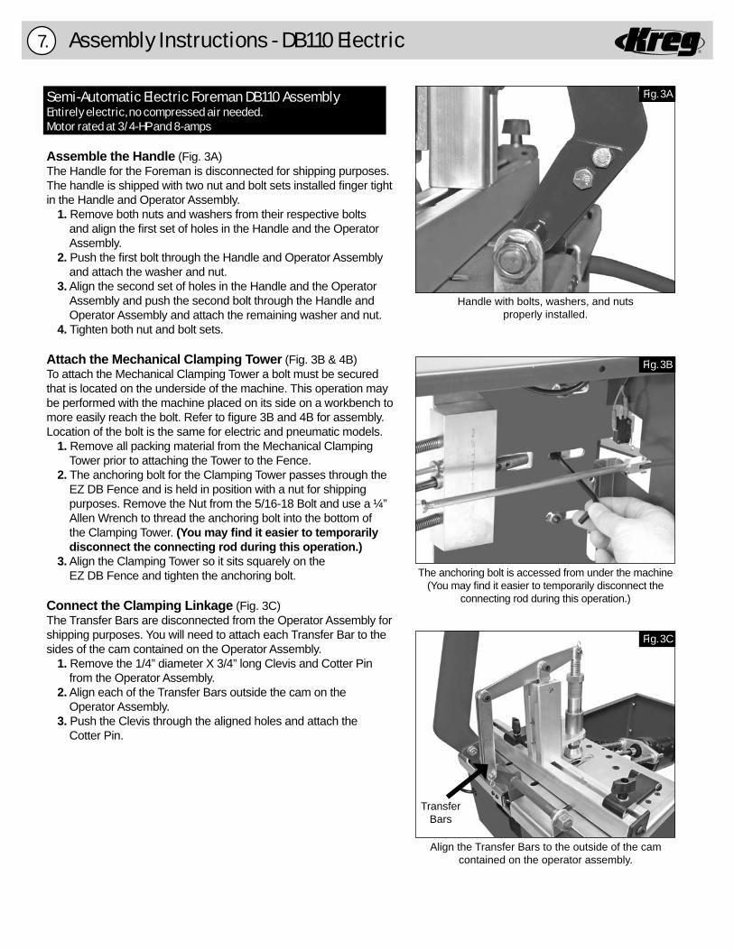
Assembly Instructions - DB110 Electric7.
Fig. 3C
Align the Transfer Bars to the outside of the camcontained on the operator assembly.
Fig. 3A
Fig. 3B
The anchoring bolt is accessed from under the machine(You may fi nd it easier to temporarily disconnect the
connecting rod during this operation.)
Handle with bolts, washers, and nutsproperly installed.
TransferBars
Semi-Automatic Electric Foreman DB110 AssemblyEntirely electric, no compressed air needed. Motor rated at 3/4-HP and 8-amps
Assemble the Handle (Fig. 3A)The Handle for the Foreman is disconnected for shipping purposes. The handle is shipped with two nut and bolt sets installed fi nger tight in the Handle and Operator Assembly. 1. Remove both nuts and washers from their respective bolts and align the fi rst set of holes in the Handle and the Operator Assembly. 2. Push the fi rst bolt through the Handle and Operator Assembly and attach the washer and nut. 3. Align the second set of holes in the Handle and the Operator Assembly and push the second bolt through the Handle and Operator Assembly and attach the remaining washer and nut. 4. Tighten both nut and bolt sets.
Attach the Mechanical Clamping Tower (Fig. 3B & 4B) To attach the Mechanical Clamping Tower a bolt must be secured that is located on the underside of the machine. This operation may be performed with the machine placed on its side on a workbench to more easily reach the bolt. Refer to fi gure 3B and 4B for assembly. Location of the bolt is the same for electric and pneumatic models. 1. Remove all packing material from the Mechanical Clamping Tower prior to attaching the Tower to the Fence. 2. The anchoring bolt for the Clamping Tower passes through the EZ DB Fence and is held in position with a nut for shipping purposes. Remove the Nut from the 5/16-18 Bolt and use a ¼” Allen Wrench to thread the anchoring bolt into the bottom of the Clamping Tower. (You may fi nd it easier to temporarily disconnect the connecting rod during this operation.) 3. Align the Clamping Tower so it sits squarely on the EZ DB Fence and tighten the anchoring bolt.
Connect the Clamping Linkage (Fig. 3C)The Transfer Bars are disconnected from the Operator Assembly for shipping purposes. You will need to attach each Transfer Bar to the sides of the cam contained on the Operator Assembly. 1. Remove the 1/4” diameter X 3/4” long Clevis and Cotter Pin from the Operator Assembly. 2. Align each of the Transfer Bars outside the cam on the Operator Assembly. 3. Push the Clevis through the aligned holes and attach the Cotter Pin.
R
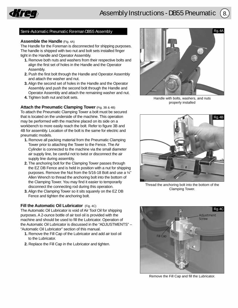
Assembly Instructions - DB55 Pneumatic 8.
Handle with bolts, washers, and nutsproperly installed
Thread the anchoring bolt into the bottom of the Clamping Tower.
Remove the Fill Cap and fi ll the Lubricator.
Fig. 4A
Fig. 4B
Fig. 4C
Fill Cap
Adjustment Screw
Semi-Automatic Pneumatic Foreman DB55 Assembly
Assemble the Handle (Fig. 4A)The Handle for the Foreman is disconnected for shipping purposes. The handle is shipped with two nut and bolt sets installed fi ngertight in the Handle and Operator Assembly. 1. Remove both nuts and washers from their respective bolts and align the fi rst set of holes in the Handle and the Operator Assembly. 2. Push the fi rst bolt through the Handle and Operator Assembly and attach the washer and nut. 3. Align the second set of holes in the Handle and the Operator Assembly and push the second bolt through the Handle and Operator Assembly and attach the remaining washer and nut. 4. Tighten both nut and bolt sets.
Attach the Pneumatic Clamping Tower (Fig. 3B & 4B) To attach the Pneumatic Clamping Tower a bolt must be securedthat is located on the underside of the machine. This operation may be performed with the machine placed on its side on a workbench to more easily reach the bolt. Refer to fi gure 3B and 4B for assembly. Location of the bolt is the same for electric and pneumatic models. 1. Remove all packing material from the Pneumatic Clamping Tower prior to attaching the Tower to the Fence. The Air Cylinder is connected to the machine via the small diameter air supply line, be careful not to twist or disconnect the air supply line during assembly. 2. The anchoring bolt for the Clamping Tower passes through the EZ DB Fence and is held in position with a nut for shipping purposes. Remove the Nut from the 5/16-18 Bolt and use a ¼” Allen Wrench to thread the anchoring bolt into the bottom of the Clamping Tower. You may fi nd it easier to temporarily disconnect the connecting rod during this operation. 3. Align the Clamping Tower so it sits squarely on the EZ DB Fence and tighten the anchoring bolt.
Fill the Automatic Oil Lubricator (Fig. 4C)The Automatic Oil Lubricator is void of Air Tool Oil for shippingpurposes. A 2-ounce bottle of air tool oil is provided with themachine and should be used to fi ll the Lubricator. Operation ofthe Automatic Oil Lubricator is discussed in the “ADJUSTMENTS” –“Automatic Oil Lubricator” section of this manual. 1. Remove the Fill Cap of the Lubricator and add air tool oil to the Lubricator. 2. Replace the Fill Cap in the Lubricator and tighten.
R
9.
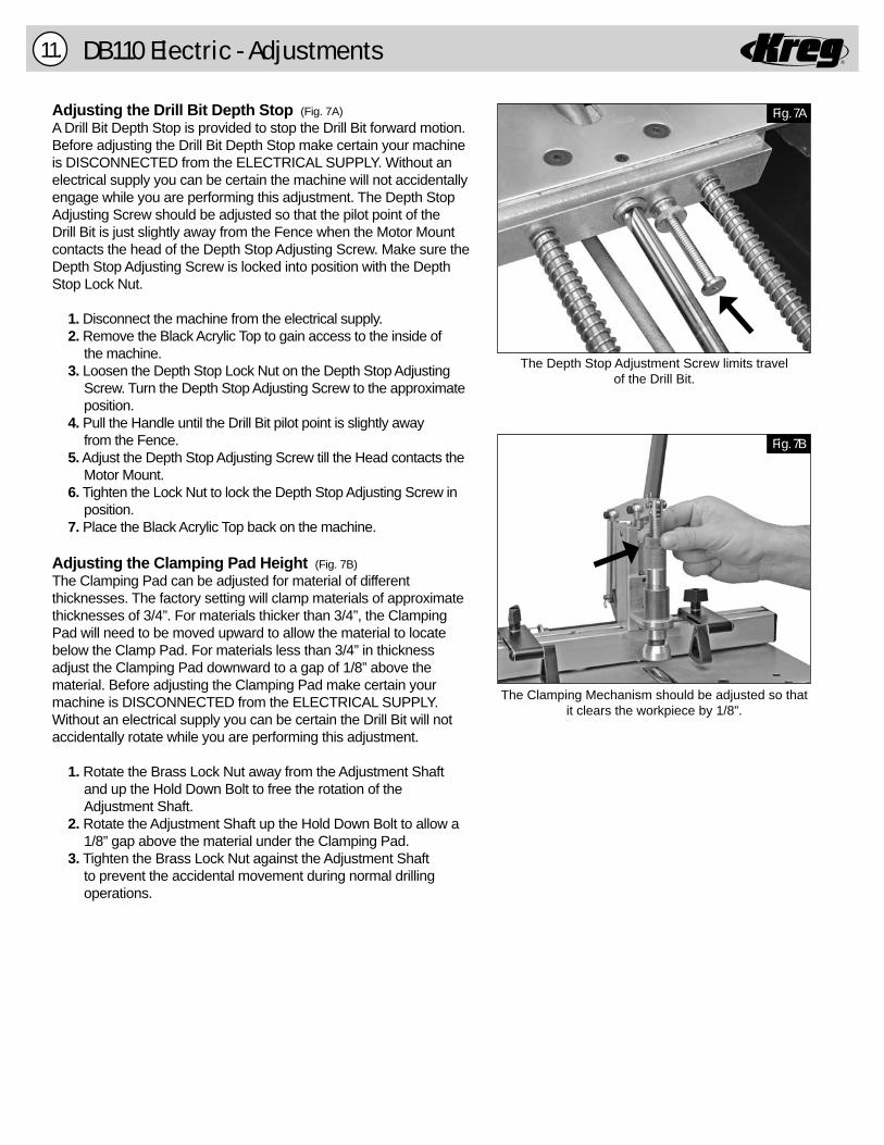
The Drill Bit is held in position with set-screwsin the Drill Adapter.
Fig. 5A
Fig. 5B
Fig. 5C
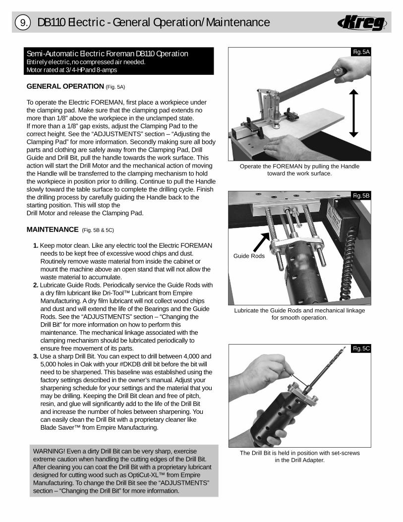
Operate the FOREMAN by pulling the Handle toward the work surface.
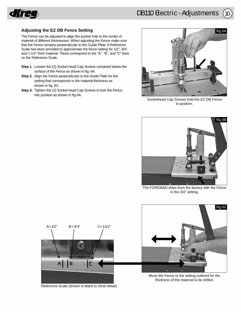
Lubricate the Guide Rods and mechanical linkage for smooth operation.
Guide Rods
Semi-Automatic Electric Foreman DB110 OperationEntirely electric, no compressed air needed. Motor rated at 3/4-HP and 8-amps
GENERAL OPERATION (Fig. 5A)
To operate the Electric FOREMAN, fi rst place a workpiece under the clamping pad. Make sure that the clamping pad extends no more than 1/8” above the workpiece in the unclamped state. If more than a 1/8” gap exists, adjust the Clamping Pad to the correct height. See the “ADJUSTMENTS” section – “Adjusting the Clamping Pad” for more information. Secondly making sure all body parts and clothing are safely away from the Clamping Pad, Drill Guide and Drill Bit, pull the handle towards the work surface. This action will start the Drill Motor and the mechanical action of moving the Handle will be transferred to the clamping mechanism to hold the workpiece in position prior to drilling. Continue to pull the Handle slowly toward the table surface to complete the drilling cycle. Finish the drilling process by carefully guiding the Handle back to the starting position. This will stop the Drill Motor and release the Clamping Pad.
MAINTENANCE (Fig. 5B & 5C)
1. Keep motor clean. Like any electric tool the Electric FOREMAN needs to be kept free of excessive wood chips and dust. Routinely remove waste material from inside the cabinet or mount the machine above an open stand that will not allow the waste material to accumulate. 2. Lubricate Guide Rods. Periodically service the Guide Rods with a dry fi lm lubricant like Dri-Tool™ Lubricant from Empire Manufacturing. A dry fi lm lubricant will not collect wood chips and dust and will extend the life of the Bearings and the Guide Rods. See the “ADJUSTMENTS” section – “Changing the Drill Bit” for more information on how to perform this maintenance. The mechanical linkage associated with the clamping mechanism should be lubricated periodically to ensure free movement of its parts. 3. Use a sharp Drill Bit. You can expect to drill between 4,000 and 5,000 holes in Oak with your #DKDB drill bit before the bit will need to be sharpened. This baseline was established using the factory settings described in the owner’s manual. Adjust your sharpening schedule for your settings and the material that you may be drilling. Keeping the Drill Bit clean and free of pitch, resin, and glue will signifi cantly add to the life of the Drill Bit and increase the number of holes between sharpening. You can easily clean the Drill Bit with a proprietary cleaner like Blade Saver™ from Empire Manufacturing.
WARNING! Even a dirty Drill Bit can be very sharp, exercise extreme caution when handling the cutting edges of the Drill Bit. After cleaning you can coat the Drill Bit with a proprietary lubricant designed for cutting wood such as OptiCut-XL™ from Empire Manufacturing. To change the Drill Bit see the “ADJUSTMENTS” section – “Changing the Drill Bit” for more information.
DB110 Electric - General Operation/Maintenance
R
DB110 Electric - Adjustments 10.
Fig. 6A
Fig. 6B
Fig. 6C
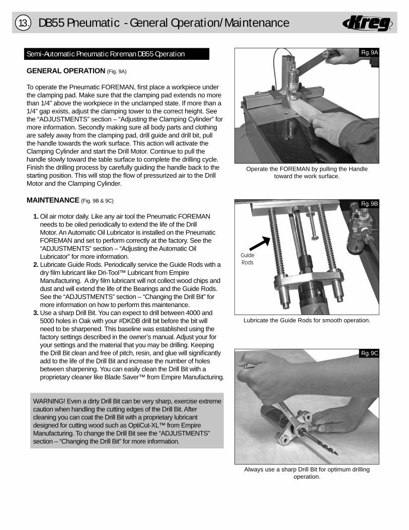
Move the Fence to the setting outlined for thethickness of the material to be drilled.
The FOREMAN ships from the factory with the Fencein the 3/4” setting.
Sockethead Cap Screws hold the EZ DB Fencein position.
Reference Scale (shown in black to show detail)
Adjusting the EZ DB Fence SettingThe Fence can be adjusted to align the pocket hole to the center of material of different thicknesses. When adjusting the Fence make sure that the Fence remains perpendicular to the Guide Plate. A Reference Scale has been provided to approximate the fence setting for 1/2”, 3/4”, and 1-1/2” thick material. These correspond to the “A”, “B”, and “C” lines on the Reference Scale.
Step 1. Loosen the (2) Socket-head Cap Screws contained below the surface of the Fence as shown in fi g. 6A.Step 2. Align the Fence perpendicular to the Guide Plate for the setting that corresponds to the material thickness as shown in fi g. 6C.Step 3. Tighten the (2) Socket-head Cap Screws to lock the Fence into position as shown in fi g 6A.
A B C
A = 1/2” B = 3/4” C = 1-1/2”
RDB110 Electric - Adjustments11.
Fig. 7A
Fig. 7B
The Depth Stop Adjustment Screw limits travelof the Drill Bit.
The Clamping Mechanism should be adjusted so that it clears the workpiece by 1/8”.
Adjusting the Drill Bit Depth Stop (Fig. 7A)A Drill Bit Depth Stop is provided to stop the Drill Bit forward motion. Before adjusting the Drill Bit Depth Stop make certain your machine is DISCONNECTED from the ELECTRICAL SUPPLY. Without an electrical supply you can be certain the machine will not accidentally engage while you are performing this adjustment. The Depth Stop Adjusting Screw should be adjusted so that the pilot point of the Drill Bit is just slightly away from the Fence when the Motor Mount contacts the head of the Depth Stop Adjusting Screw. Make sure the Depth Stop Adjusting Screw is locked into position with the Depth Stop Lock Nut.
1. Disconnect the machine from the electrical supply. 2. Remove the Black Acrylic Top to gain access to the inside of the machine. 3. Loosen the Depth Stop Lock Nut on the Depth Stop Adjusting Screw. Turn the Depth Stop Adjusting Screw to the approximate position. 4. Pull the Handle until the Drill Bit pilot point is slightly away from the Fence. 5. Adjust the Depth Stop Adjusting Screw till the Head contacts the Motor Mount. 6. Tighten the Lock Nut to lock the Depth Stop Adjusting Screw in position. 7. Place the Black Acrylic Top back on the machine.
Adjusting the Clamping Pad Height (Fig. 7B)The Clamping Pad can be adjusted for material of different thicknesses. The factory setting will clamp materials of approximate thicknesses of 3/4”. For materials thicker than 3/4”, the Clamping Pad will need to be moved upward to allow the material to locate below the Clamp Pad. For materials less than 3/4” in thickness adjust the Clamping Pad downward to a gap of 1/8” above the material. Before adjusting the Clamping Pad make certain your machine is DISCONNECTED from the ELECTRICAL SUPPLY. Without an electrical supply you can be certain the Drill Bit will not accidentally rotate while you are performing this adjustment.
1. Rotate the Brass Lock Nut away from the Adjustment Shaft and up the Hold Down Bolt to free the rotation of the Adjustment Shaft. 2. Rotate the Adjustment Shaft up the Hold Down Bolt to allow a 1/8” gap above the material under the Clamping Pad. 3. Tighten the Brass Lock Nut against the Adjustment Shaft to prevent the accidental movement during normal drilling operations.

RDB110 Electric - Adjustments 12.
Adjust the Swing Stop to locate the materialfor repetitive drilling.
Fig. 8A
The Drill Bit is held in position with set-screwsin the Drill Adapter.
Fig. 8B
Fig. 8C
Disconnect the Connecting Rod to remove theElectric Drill Motor from the Guide Rods.
Push motor in slightly and lift assembly up until latch catches on left side of machine.
Tip
This latch will automatically catchand hold assembly in place.
This will allow you to performmaintenance easily on your machine.
Semi-Automatic Electric Foreman DB110 OperationADJUSTMENTS (Cont’)
Swing Stops (Fig. 8A)Two Swing Stops are provided to assist in drilling pocket holes in the same location on multiple workpieces of the same dimension. When the Swing Stop is not used, it will pivot out of the way to allow the workpiece to slide underneath and rest against the fence. To change the location of the Swing Stop simply loosen the knob, move to the new location and tighten the knob to lock the Swing Stop in position.
Changing the Drill Bit (Fig. 8B & 8C)IMPORTANT! Before changing the Drill Bit, make certain yourmachine is DISCONNECTED from the ELECTRICAL SUPPLY. Without an electrical supply you can be certain the Drill Bit will not accidentally engage while you are performing this adjustment.
1. Disconnect the machine from the electrical supply. 2. Remove the Black Acrylic Top to gain access to the inside of the machine. 3. Lift the Tool Plate as it pivots on the hinges till the Safety Latch engages to hold the Tool Plate in position. 4. Remove the Clevis and Cotter Pin from the Connecting Rod to disconnect the Connecting Rod from the Motor Mount. 5. Remove the Drill Motor and Motor Mount assembly. NOTE: Now is a good time to clean and lubricate the Guide Rods according to the “MAINTENANCE” section of this manual. 6. Loosen both Set-screws with the hex key that hold the Drill Bit in place inside the Dill Adapter. 7. Insert a new or re-sharpened Drill Bit into the Drill Adapter, aligning the fl ats on the Drill Bit shank with the set-screws in the Drill Adapter. 8. Tighten the set-screws front and back to maintain equal pressure on the Drill Bit shaft. 9. Re-install the Drill Motor and Motor Mount assembly on the Guide Rods. 10. Connect the Clevis and Cotter Pin through the Connecting Rod and Motor Mount. 11. Lift the Tool Plate to disengage the Safety Latch and lower the Tool Plate into position. 12. Check the Drill Bit Depth Stop settings for the material thickness being drilled. 13. Place the Black Acrylic Top back on the machine.
R
DB55 Pneumatic - General Operation/Maintenance13.
Fig. 9A
Operate the FOREMAN by pulling the Handletoward the work surface.
Fig. 9B
Fig. 9C
Lubricate the Guide Rods for smooth operation.
Always use a sharp Drill Bit for optimum drilling operation.
Guide Rods
Semi-Automatic Pneumatic Foreman DB55 Operation
GENERAL OPERATION (Fig. 9A)
To operate the Pneumatic FOREMAN, fi rst place a workpiece under the clamping pad. Make sure that the clamping pad extends no more than 1/4” above the workpiece in the unclamped state. If more than a 1/4” gap exists, adjust the clamping tower to the correct height. See the “ADJUSTMENTS” section – “Adjusting the Clamping Cylinder” for more information. Secondly making sure all body parts and clothing are safely away from the clamping pad, drill guide and drill bit, pull the handle towards the work surface. This action will activate the Clamping Cylinder and start the Drill Motor. Continue to pull the handle slowly toward the table surface to complete the drilling cycle. Finish the drilling process by carefully guiding the handle back to the starting position. This will stop the fl ow of pressurized air to the Drill Motor and the Clamping Cylinder.
MAINTENANCE (Fig. 9B & 9C)
1. Oil air motor daily. Like any air tool the Pneumatic FOREMAN needs to be oiled periodically to extend the life of the Drill Motor. An Automatic Oil Lubricator is installed on the Pneumatic FOREMAN and set to perform correctly at the factory. See the “ADJUSTMENTS” section – “Adjusting the Automatic Oil Lubricator” for more information. 2. Lubricate Guide Rods. Periodically service the Guide Rods with a dry fi lm lubricant like Dri-Tool™ Lubricant from Empire Manufacturing. A dry fi lm lubricant will not collect wood chips and dust and will extend the life of the Bearings and the Guide Rods. See the “ADJUSTMENTS” section – “Changing the Drill Bit” for more information on how to perform this maintenance. 3. Use a sharp Drill Bit. You can expect to drill between 4000 and 5000 holes in Oak with your #DKDB drill bit before the bit will need to be sharpened. This baseline was established using the factory settings described in the owner’s manual. Adjust your for your settings and the material that you may be drilling. Keeping the Drill Bit clean and free of pitch, resin, and glue will signifi cantly add to the life of the Drill Bit and increase the number of holes between sharpening. You can easily clean the Drill Bit with a proprietary cleaner like Blade Saver™ from Empire Manufacturing.
WARNING! Even a dirty Drill Bit can be very sharp, exercise extreme caution when handling the cutting edges of the Drill Bit. After cleaning you can coat the Drill Bit with a proprietary lubricant designed for cutting wood such as OptiCut-XL™ from Empire Manufacturing. To change the Drill Bit see the “ADJUSTMENTS” section – “Changing the Drill Bit” for more information.
RDB55 Pneumatic - Adjustments 14.
Fig. 10A
Fig. 10B
Fig. 10C
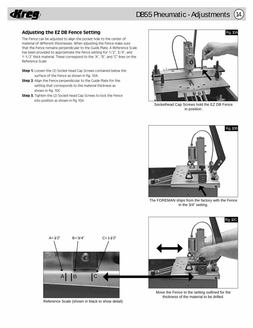
Sockethead Cap Screws hold the EZ DB Fencein position.
The FOREMAN ships from the factory with the Fence in the 3/4” setting.
Move the Fence to the setting outlined for the thickness of the material to be drilled.
Adjusting the EZ DB Fence SettingThe Fence can be adjusted to align the pocket hole to the center of material of different thicknesses. When adjusting the Fence make sure that the Fence remains perpendicular to the Guide Plate. A Reference Scale has been provided to approximate the fence setting for 1/2”, 3/4”, and 1-1/2” thick material. These correspond to the “A”, “B”, and “C” lines on the Reference Scale.
Step 1. Loosen the (2) Socket-head Cap Screws contained below the surface of the Fence as shown in fig. 10A.Step 2. Align the Fence perpendicular to the Guide Plate for the setting that corresponds to the material thickness as shown in fig. 10C.Step 3. Tighten the (2) Socket-head Cap Screws to lock the Fence into position as shown in fig 10A.
Reference Scale (shown in black to show detail)
A B C
A = 1/2” B = 3/4” C = 1-1/2”
RDB55 Pneumatic - Adjustments15.
Fill Cap
Adjustment Screw
Fig. 11A
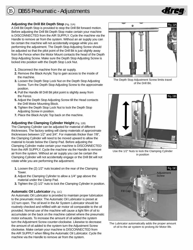
The Depth Stop Adjustment Screw limits travelof the Drill Bit.
Use the 1/2” Nuts to lock the Clamping Cylinder in position
The Lubricator automatically adds the proper amount of oil to the air system to prolong Air Motor life.
Fig. 11B
Fig. 11C
Adjusting the Drill Bit Depth Stop (Fig. 11A)A Drill Bit Depth Stop is provided to stop the Drill Bit forward motion. Before adjusting the Drill Bit Depth Stop make certain your machine is DISCONNECTED from the AIR SUPPLY. Cycle the machine via the Handle to remove air from the system. Without an air supply you can be certain the machine will not accidentally engage while you are performing the adjustment. The Depth Stop Adjusting Screw should be adjusted so that the pilot point of the Drill Bit is just slightly away from the Fence when the Motor Mount contacts the head of the Depth Stop Adjusting Screw. Make sure the Depth Stop Adjusting Screw is locked into position with the Depth Stop Lock Nut.
1. Disconnect the machine from the air supply. 2. Remove the Black Acrylic Top to gain access to the inside of the machine. 3. Loosen the Depth Stop Lock Nut on the Depth Stop Adjusting Screw. Turn the Depth Stop Adjusting Screw to the approximate position. 4. Pull the Handle till Drill Bit pilot point is slightly away from the Fence. 5. Adjust the Depth Stop Adjusting Screw till the Head contacts the Drill Motor Mounting Block. 6. Tighten the Depth Stop Lock Nut to lock the Depth Stop Adjusting Screw in position. 7. Place the Black Acrylic Top back on the machine.
Adjusting the Clamping Cylinder Height (Fig. 11B)The Clamping Cylinder can be adjusted for material of different thicknesses. The factory setting will clamp materials of approximate thicknesses between 1/2” and 3/4”. For materials thicker than 7/8”, the Clamping Cylinder will need to be moved upward to allow the material to locate below the Clamp Pad. Before adjusting the Clamping Cylinder make certain your machine is DISCONNECTED from the AIR SUPPLY. Cycle the machine via the Handle to remove air from the system. Without an air supply you can be certain the Clamping Cylinder will not accidentally engage or the Drill Bit will not rotate while you are performing the adjustment.
1. Loosen the (2) 1/2” nuts located on the rear of the Clamping Tower.
2. Adjust the Clamping Cylinder to allow a 1/4” gap above the material under the Clamp Pad.
3. Tighten the (2) 1/2” nuts to lock the Clamping Cylinder in position.
Automatic Oil Lubricator (Fig. 11C)An Automatic Oil Lubricator is provided to maintain proper lubrication to the pneumatic motor. The Automatic Oil Lubricator is preset at 1/2 turn open. The oil level in the Air System Lubricator should be routinely checked and refi lled with air motor oil comparable to the oil provided. Normal use of the machine will cause a light fi lm of oil to accumulate on the back on the machine cabinet where the pneumatic motor exhausts. To increase the amount of oil added the system turn the Adjustment Screw counter-clockwise. Likewise to decrease the amount of oil added to the system turn the Adjustment Screw clockwise. Make certain your machine is DISCONNECTED from the AIR SUPPLY when fi lling the Automatic Oil Lubricator. Cycle the machine via the Handle to remove air from the system.

RDB55 Pneumatic - Adjustments 16.
Adjust the Swing Stop to locate the materialfor repetitive drilling.
Disconnect the Connecting Rod to remove theAir Drill Motor from the Guide Rods.
Loosen or tighten the collet with 9/16” & 3/4”open ended wrenches.
Fig. 12A
Fig. 12B
Fig. 12C
Push motor in and lift assembly up until latch catches on left of machine.
Tip
This latch will automatically catchand hold assembly in place.
This will allow you to perform maintenance easily on your machine.
Semi-Automatic Pneumatic Foreman DB55 OperationADJUSTMENTS (Cont’)
Swing Stops (Fig. 12A)Two Swing Stops are provided to assist in drilling pocket holes in the same location on multiple work pieces of the same dimension. When the Swing Stop is not used, it will pivot out of the way to allow the work piece to slide underneath and rest against the fence. To change the location of the Swing Stop simply loosen the knob, move to the new location and tighten the Knob to lock the Swing Stop in position.
Changing the Drill Bit (Fig. 12B & 12C)IMPORTANT! Before changing the Drill Bit, make certain your machineis DISCONNECTED from the AIR SUPPLY. Cycle the machine via the Handle to remove air from the system. Without an air supply you can be certain the Drill Bit will not accidentally engage while you are performingthis adjustment. While the air supply line is disconnected from the Air Motorpressurized air with lubricating oil will be vented inside the cabinet if the handle is accidentally moved to the operating position unless the machineis DISCONNECTED from the AIR SUPPLY.
1. Disconnect the machine from the air supply. 2. Remove the Black Acrylic Top to gain access to the inside of the machine. 3. Disconnect the air supply line from the Air Motor by pushing in the collar on the inlet fi tting of the Air Motor and simultaneously pull out the tubing. 4. Lift the Tool Plate as it pivots on the hinges till the Safety Latch engages to hold the Tool Plate in position. 5. Remove the Clevis and Cotter Pin from the Connecting Rod to disconnect the Connecting Rod from the Drill Motor Mounting Block. 6. Remove the Drill Motor and Motor Mount assembly. NOTE: Now is a good time to clean and lubricate the Guide Rods according to the “MAINTENANCE” section of this manual. 7. Use 9/16” and 3/4” open ended wrenches to loosen the Collet. Remove the dull Drill Bit from the Collet. 8. Insert a new or re-sharpened Drill Bit into the Collet, be sure to fully insert the bit until it comes to rest at the bottom of the collet. 9. Use 9/16” and 3/4” open ended wrenches to tighten the Collet. 10. Re-install the Drill Motor and Motor Mount assembly on the Guide Rods. 11. Connect the Clevis and Cotter Pin through the Connecting Rod and Drill Motor Mounting Block. 12. Lift the Tool Plate to disengage the Safety Latch and lower the Tool Plate into position. 13. Make sure the air supply line for the Air Motor is free of debris then connect the air supply line to the Air Motor by pushing in the tubing until it seats in the inlet fi tting of the Air Motor. 14. Check the Drill Bit Depth Stop settings for the material thickness being drilled. 15. Place the Black Acrylic Top back on the machine.

R
Warranty17.
WARRANTYForeman Semi-Automatic Pocket Hole Machines
Kreg Tool Company warrants to its authorized distributors of Kreg products and the original purchasers from such distributors, the #DB55 and DB110 Foreman Semi-Automatic Pocket Hole Machine to be free of defects in materials and workmanship for a period of one (1) year from the date of de-livery to the original purchaser. During said warranty period Kreg will, at its option, repair or replace any product (or component part thereof) proving defective during said period. This warranty applies only to products which are used in accordance with all instructions as to operation, maintenance and safety set forth in catalogs, manuals, and/or instruction sets furnished by Kreg Tool Company.
This warranty becomes effective only if the accompanying card is fully and properly completed and returned to Kreg Tool Company within ten (10) days from date of delivery to the original purchaser.
The drill guide will carry a lifetime warranty. This warranty does not apply to items that would normally be consumed or require replacement due to normal wear (drill bits, lubricants, etc.); for the cost of removal of components if such removal is authorized by Kreg Tool Company; for shipment to Kreg Tool Company’s repair facility; or for reinstal-lation.
This warranty is null and void if the product has been subjected to (1) misuse, abuse or improper service or storage; (2) accident, neglect, damage or other circumstances beyond Kreg Tool Company’s control; (3) modifi cations, disassembly, tampering, alterations or repairs outside of Kreg Tool Com-pany’s factory not authorized by Kreg Tool Company; (4) to any product not bearing its original serial number plate; and (5) for non-original purchas-ers. This warranty does not apply to normal wear and tear, corrosion, abrasion, or repairs required due to natural causes or acts of God.
To obtain warranty service contact the distributor from which the FOREMAN Pocket Hole Boring Machine was purchased, or you may contact Kreg Tool Company directly. Proof of purchase will be required before remedy will be provided under the terms of this warranty. Kreg Tool Company assumes no responsibility for products which are returned without prior authorization. Kreg Tool Company’s obligations under this warranty shall be exclusively limited to repairing or replacing (at Kreg Tool Company’s option) products which are determined by Kreg Tool Company to be defective upon delivery at Kreg Tool Company’s factory, and on inspection by Kreg Tool Company. Under no circumstance shall Kreg Tool Company be liable for incidental or consequential damages resulting from defective products, nor shall Kreg Tool Company’s liability exceed the purchase price paid for the product by the original purchaser.
This is Kreg Tool Company’s sole warranty. Any and all other warranties which may be implied by law, including any warranties for merchantability or fi tness for a particular purpose, are hereby limited to the duration of this warranty. Kreg Tool Company shall not be liable for any loss, damage or expense directly or indirectly related to the use of its products or from any other cause or for consequential damages (including without limitation, loss of time, inconvenience, and loss of production). The warranty contained herein may not be modifi ed and no other warranty, expressed or implied, shall be made by or on behalf of Kreg Tool Company.
Please register your warranty by sending the separate warranty registration card.
Keep this form for your records.
For your records the following information will be useful in the event warranty service is required. For complete records attach copy of purchase invoice to this form.
Date of Purchase: ____/____/____
Purchased From:
Serial Number: (serial number is located on the side of the machine)
Kreg Tool Company, 201 Campus Drive, Huxley, IA 50124
800.447.8638 • www.kregtool.com
R
PLEASE DO NOT RETURN MACHINE BACK TO DEALER IF WARRANTY ISSUES ARISE.CONTACT KREG TOOL COMPANY AT THE ABOVE ADDRESS.

R
Notes 18.

R
Notes
Kreg Tool Company, 201 Campus Drive, Huxley, IA 50124800.447.8638 • www.kregtool.com
R