r Executive Summar.y Structural Arrangement Trade Study · NASA - ROCKWELUSSD - NORTHROP/GRUMMAN -...
30
r j SSD95D0069 Vol. 1 Executive Summar.y Structural Arrangement Trade Study Reusable Hydrogen Composite Tank System (RHCTS) and Graphite Composite Primary Structures (GCPS) Cooperative A_reements NCC8-39 and NCC1-193 J March 14, 1995 Prepared for: NASA Marshall Space Flight Center Langley Research Center Ames Research Center (I_ Rockwell Ae_pace Space SystemsDivision _IORI_ROP CRt.II, IMAN _lb Rockwell Aerospace North American Aircraft https://ntrs.nasa.gov/search.jsp?R=19950016771 2018-08-20T03:58:02+00:00Z
Transcript of r Executive Summar.y Structural Arrangement Trade Study · NASA - ROCKWELUSSD - NORTHROP/GRUMMAN -...

r
jSSD95D0069
Vol. 1
Executive Summar.y
Structural Arrangement Trade Study
Reusable Hydrogen Composite Tank System (RHCTS)and
Graphite Composite Primary Structures (GCPS)
Cooperative A_reements NCC8-39 and NCC1-193 J
March 14, 1995
Prepared for:NASA
Marshall Space Flight CenterLangley Research Center
Ames Research Center
(I_ Rockwell Ae_pace
Space SystemsDivision
_IORI_ROP CRt.II, IMAN _lb Rockwell Aerospace
North American Aircraft
https://ntrs.nasa.gov/search.jsp?R=19950016771 2018-08-20T03:58:02+00:00Z

Briefing Objectives J
SSTO _'_'f/i" v
To present the Trade study process, requirements used, analysisperformed, and data generated
To present the derived Conclusions and Recommendations
Through understanding of the above arrive at NASA/RI cooperative team jointdecisions pertaining to TA 1 and TA 2 future structural developments
NASA - ROCKWELUSSD - NORTHROP/GRUMMAN - ROCKWELI.JNAAD/TULSA - HERCULES I

AgendaSSTO
Trade Study ObjectiveRequirementsOperability FeaturesSubsystems Supporting AnalysisStructural Arrangement OptionsSelection ProcessConclusions and Recommendations
NASA - ROCKWELL/SSD - NORTHROP/GRUMMAN - ROCKWELL/NAADFrULSA - HERCULES I

Trade Study Objectives _J
SSTO _FF/,_- v
Determine the most suitable vehicle structural arrangement and structural
materials applications recognizing:
The most suitable vehicle structural arrangement contains the most
suitable Major Structures, i.e, Hydrogen and LO Tankage concepts,Intertank, wing and Thrust Structure concepts
Consider other potential technology development needs
On the basis of the foregoing recommend the Major Structures for continuingdevelopment in TA 1 and TA 2
NASA - ROCKWELL/SSD - NORTHROP/GRUMMAN - ROCKWELL/NAAD/TULSA - HERCULES I

V
ajor Requirements/Guidelines Direct Trade ,StudySSTORequirements
• Satisfy the National Launch needs- Space Station Missions
• Deliver and return payloads/crews to and from 220 nmi circular/51.6 ° orbit• Provide high degree of reliability and passenger safety per flight• Acceptable cost• Environmentally acceptable (EPA standards, etc.)
Assumptions• Capable of delivering/returning 25,000 Ib to/from Space Station• Payload Bay Volume: 15 x 30 ft• Mission Duration: 2 to 7 days• Airframe Life: 100 missions/20 years• OMS Delta V Budget: 1,100 ft/s• RCS Delta V Budget: 110 ft/s• Cross Range: 1,100 nmi• Capable of withstanding rainstorm on launch pad• Dry Weight Growth Margin: 15%• Autonomous operations (ground and flight)• Parallel, off-line processing of payloads
- Standardized interfaces
° Off-line regularly scheduled depot maintenance
NASA- ROCKWELL/SSD - NORTHROP/GRUMMAN - ROCKWELI_/NAAD/TULSA - HERCULES II

24 ........ConfigurationStructural Arrangement Options StudiedssTo_441A Separate Tanks 2A Tanks
-1, 3 Skin-stringer LH tank ,.,e_,ara,=-2,4 Sandwich LH Tank
-3, 4 Wing not attached to LO Tank
'_,_ FwdLHTank
__:,_ _MId Payload Bay
with one RP Tank
_/_,)VI_F-_, _'Aft LO TankV/ " Shell Thrust Structure
-1, 3 Skin-stringer LH tank-2 Sandwich LH Tank
-3 Wing not attached to LH Tank
Fwd LO Tank
Shell Thrust Structure
3A Common Bulkhead
-1 Skin-stringer LH tank
-2 Sandwich LH Tank
::::_::_ with four RP Tanks
V " ShelIThrust Structure
4A Common Bulkhead-1 Skin-stringer LH tank-2 Sandwich LH tank
Fwd LH Tank
kft LO Tank
Aft Payload Baywith one RP Tank
Truss Thrust Structure for -1Shell Thrust Structure for -2

Wide Range of Structural Materials/TPS Options StudiedssTo
1A-1
Intertank Option 11
AFRSI or TABI
< 550 Fm
AFR 700 -Polyimide HC Core
1B-1 and 2B-1Non-Integral Tank
Option 7
AFRSI or TABI
I °,It lJllHi tlllUlltlllLliUm
AFR 7OO
_/--_olylmlde HC Cor<e=s0F
_- I!HL[!l]!lil;[I]littliNIHHi]iHillHilll<_.L'"'' - _ IM7/977-2
2A-1
Intertank and Wing
Option 10(Mechsnlcmlltf
CSIC Panels ...¢_,_
< 550 Fm
AFR 700 -Polyimide HC Core
Intertank, Wing, Tailand Control Surfaces
Option 11
AFRSI, TABI or AETB
AFR 700 -Polyimide HC Core
Wing Option 12
(Mochanlcally
CSIC Panels ..o=_,_}
< 1200F
Control Surface
Option 14(Mechmnlcmlty
CSIC Panels x,,.=h.=_
< 1200F
TMC Blackglas
NASA - ROCKWELL/SSD - NORTHROPIGRUMMAN - ROCKWELIJNAAD/TULSA - HERCULES.,m

Vehicle Design IncorPorat"esOPerability Features _jVehicle Uiilizes "Clean Pad" SSTO ._7 _t
(No Tower) Approach
JOINTLESS TANKELIMINATES
POTENTIAL LEAKS
SIMPLE PLCANISTER
(3 TYPES) WITHHORIZONTAL
LOADING _
TPS PLACED OUTSIDETANKS TO EASE
WALL INSPECTIONS
\
8 HINGED DOORS IN ENGINE
FAIRINGS FOR SUBSYSTEMS
ACCESSIBILITY
MODULAR RCS SYSTEMS
USE SAME PROPELLANTS
AS MPS Structure Designed to MaximizeEase of Inspection
NASA - ROCKWELL/SSD - NORTHROP/GRUMMAN - ROCKWELL/NAAD/TULSA - HERCULES

Study Addressed Key Structural Design DetailSsT °LH Tank Y-Joint Concept for Sandwich Cylinder
I /Solid Laminate Filleri / /Foam Filler
Rohacell CaM_III____
Wing Attachment to LH Tank - High Design Risk
ADHESIVE
D LINE
WING ATTACH
FITrlNGTANK _
KEENSERT/ _TANK SKIN
Chine Support Avoids Penetration of Tank
l1_3
Tta__ W_F_"n_
NASA - ROCKWELL/SSD - NORTHROP/GRUMMAN - ROCKWELL/NAAD/TULSA - HERCULES II
9

Study Addressed Key ruc =lral
Potential Common Bulkhead Joint Concept
_, 17.8 I_
w,_ "r=',_e_Polnt" C_..o_tPU,, . S%_P_\ 7' ....._._c-_h.... , n ' --- ,
,, 1.";:.._ ::.;,'.i,>':':...::.': ).,! _.,:.:'.;-.:_::. ".::, ;.'.'.,."'__ '.'; :"-', " f: . : i": : ".;;.,:-_.f_-_..__ _,-=L.j___ _ r/ll,.-A-I/ _...__ _:
II AI.dJMachlned He Pu_je Channel , --/ I \
,o.0 "Wame"OrU ..... ____ \ _u=tWeUu,.,_ r'assages _ Inner Face
I ,' Adhesive Bond\
_,.._ Outer Face Sheet
Thrust Structure Hold Down Concept
t I
¢=nP¢=--- - .; "-
AP
Door
Design Details (con't. ssTo
Fairing for Access to Propulsion System
Base Holddown Fitting(11 Plcs)
Post
Longeron(8 Pica)
Aft Skirt Assy
Modular RCS System(2PIcs)
Note: Not to Scale
NASA - ROCKWELL/SSD - NORTHROP/GRUMMAN - ROCKWELL/NAAD/TULSA - HERCULES
10

1A-1 and 1A-1 Intertank Option 11 Have Lowest j_
1A-1
1A-2
1A-3
1A-4
1B-1
2A-1
2A-2
2A-3"
2B-1
3A-1
3A-2
4A-1
4A-2
1A-1 - Int-Optl 1
2A-1 -Int-Optl0
2A-1 - Int-Optl 1
2A-1 - Wg-Optl0
2A-1 - Wg-Optl 1
2A-1 - Wg-Opt12
2A-1 - TI-Optl 1
2A-1 - CS-Optl 1
2A-1 - CS-Opt14
2A-3 - Wg-Optl 1
2B-1-OTF5
-- ] _ C E
_I
. . 7
- . I
]L _ C
1 _ L _ ]
"r r L ]
]•r r i ]i E J--
: L_ ]t I -7
_-- = _ F-.... -" i - 2_ .
0 K 500 K 1000 K 1500 K 2000 K 2500 K 3000 K 3500 K
I NASA - ROCKWELL/SSD- NORTHROP/GRUMMAN - ROCKWELL/NAAD/TULSA - HERCULES
11

/2
41 Selection Criteria Are Used SSTO
2)a.
b,C.
1. DESIGN AND PRODUCTION 5)EFFORT- 10% a.
b.a. Certification Effort - 3% c.b. Verification Effort- 3%c. Producibility Effort- 2%d. IHM Effort- 2% 6)
a.
b.C.
d.
MISCELLANEOUS WEIGHTS - 6%
Primary Structure Weight - 2%TPS Weight - 1%Total Dry Weight - 3%
3) GROSS FUELED WEIGHT- 14%
a. Gross Fueled Weight Sensitivity- 14%
4) PROPULSION INTERFACE - 6%a. Number Of Feed Line Penetrations -
1.5%b. Number Of Propellant Suction Lines-
1.5%c. Ease Of Slosh Baffle Integration- 1.5%d. Ease Of Tank Cleaning - 1.5%
VEHICLE CONTROLLABILITY - 9%Ascent Controllability - 3%Hypersonic Controllability - 3%Subsonic Controllability - 3%
ON PAD OPERATIONS - 12%
Pressurization/fueling Flexibility - 3%Sub-Systems For On-Pad Operations - 3%Systems Requiring Disconnects - 3%Facilities - 3%
7) MAINTENANCE OPERATIONS - 18%
a. Wide Area Coverage Inspection - 4%b. Localized Area Coverage Inspection - 2%c, Accessibility- 1%d. Number of Inspection Points - 2%e. Re-Waterproofing- 1.5%f. Sustained Personnel- 1.5%g. Turn Around Time - 3%h. Facilities- 1.5%i. Equipment Requirements- 1.5%
8) SAFETY - 15%
a. Probability of TankPenetration - 6%
b. Tank Rupture Due ToDebris Impact - 4%
c. Numberof FractureCritical Parts - 2%
d. Probability of LH/LOContact - 1%
e. Amenability to IHM - 2%
9) DEVELOPMENTRISK- 10%
a. Structural Design Risk-3%
b. TPS Design Risk- 3%c. Technology Development
- 4%
10) COST
a. DDT&E Costb. Operations Costc. Production Costd. Life Cycle Coste, Cost Per Flight
t NASA- ROCKWELIJSSD - NORTHROP/GRUMMAN - ROCKWELIJNAAD/TULSA - HERCULES
12

Example Criteria Evaluation
1A Option Ranked Best For Certification Effortssro
effort of analysis, development testing, and demonstration testing required for certification of structure and i
la. Certification Effort - (Qualitative evaluation) - The candidate vehicle options are rated according to the perceived
TPS. Certification refers to only the design and is achievable without fabrication of a vehicle.
1A-11A-21A-31A-41B-12A-12A-22A-32B-13A-13A-24A-14A-2
1A-1 - Int-Optl 12A-1 - Int-Optl02A-1 - Int-Optl 1
2A-1 - Wg-Optl02A-1 - Wg-Optl 12A-1 - Wg-Opt12
2A-1 - TI-Opll 12A-1 - CS-Optl 12A-1 - CS-Opt142A-3 - Wg-Opll 1
2B-1 -OTF5
Certification (Low Is Best)
I
i
II
IJlI
)I
I
1I
I
=lh
I
II
.... i
I!
I
I
I
I
I
I
!
i
I
I
f
I I
I I
t I
II
I
I
I
I
!
I
I
I
I
rJ] Analysis
[__ Develol Jment Te__L
_] Demonstration
g
Testing
1A-11A-21A-31A-41B-12A-12A-22A-32B-13A-13A-24A-14A-2
1A-1 - Int-Optl 12A-1 -Int-Optl02A-1 - Int-OpI11
2A-1 - Wg-Optl02A-1 - Wg-Optl 12A-1 - Wg-Opt12
2A-1 - TI-Op1112A-1 - CS-Optl 12A-1 - CS-Opt142A-3 - Wg-Opll 1
2B-1-OTF5
Ranking (High Is Best)
! t ! iI
' I ' ] i
t II I! [ f
I
Basic Conf.
TPS Options
0 1 2 3 4 5 6 0 2 4 6 8 10
I NASA - ROCKWELIJSSD - NORTHROP/GRUMMAN - ROCKWELL/.NAAD/TULSA - HERCULES
13

• C go " S " d T p Le el Ch tMajor ate rues ummaruze o To v arcosT-0_ / _ SSTO _" 7///
Trade Oplion _ _ "_. "/_
Sek clion Criteria / W! I 5c°rel wr0 1:scor_ ,
DOt DEVELOPMENT RISK- 10% / _._
Trade Oplion 14 I A"IL-.,J._,_,_,_ _
op,'Se°_i°nc,_e,ia / wt lSco,eI WrdIScor% _ _ _ __is.,ISAEn'-'_S_ / _. _ _ TOP LEVEL RESULTS
_roI-'"1 Trade Option t4 1 l_ _ _ _ "--'Je O-tion # 1A- 1 1A-2 /,OlCEj_ wt _ -_ _ _ .,d,., _ . .IIFl _r¢ MAINTENANCE OI_ERATIONS" 1"8';,<, " - / __ _ _ _ Selection Criteria Wt Score I Wt'cl Score! y
LIEJT--_:)er T,ade lion# 1A-1 l^-,7 _ _- _ DESIGN AND o J_---'1___ _ I wt pcorelWrdIScoreJ_ - _ _ r'r_"r_"TION EFFORT 10 Yo 0{ 0(-;_l[_ :let eVk: ON PAD OPERATIONS -1L_ /' "__ _ ==_ rnuuu,,..., .=
_"-I we Nu r_= Tradepption_ ____" " _ _ MISCELLANEOUS ^o/ ^i ,., 00i \We ghtc pal .oc Selection Criteria / Wt I Scorel Wrd I Sc )rel_ _ It^tEI__UT¢ _ 13 7o U i U
-- _rc nsr p,_ VEHICLE CON'FROLLABILITyo 9% _._ _ ;vvCu_nuo i
:or _ fleo Trade Option _ I IA-1 I 1A2 _ t"r_--Dt't_¢2 Er IE/EI'_ --
-- '¢': Su ction Criteria, | W! I Scorel wrd ] Scorel wr _ _ n,.,,,.,,_, ,u,..,-,..,., 14Oyo 0 _ 0 OiAm _ur op GROSS FUELED WEIGHT- 14% _=_ WEIGHT SENSITIVITY
sy, ""-- PROPULSION O!dis Seleclion Criteria -- _ 6% 0_,e -- PROPULSION INTERFACE - 6% INTERFACE
SU,-- SelectionCriteria VEHICLE g% 0 0!
W, Nu_ MISCELLANEOUS WEIGHTS- 6% _ CONTROLLABILITY i =-ru, "=' _e. .....! --i--
Selection Criteria ON PAD OPERATIONS 12% 01 0 0_0j Q
Facn,_ DESIGN AND PRODUCTION EFFORT - 10% ___ _____ |
TradeOption # 1A-1 MAINTENANCE 18% O) 0 O)Equipment inteFF Criteria Wt OPERATIONS j
CertificationEffort 30% C [we SAFETY 15% 0_ 0
3r :ffort 30% 0 i!
} DEVELOPMENT RISK 10% 01 0 0! 0_v, 20% 0 =,
Producibility Effort I iCOST O) 0 Oi q
IIHM Effort 20"/c 0 ) i i /100o/, ) ! 100% ! 0
|Weighted Score 0.00 Weighted Score 0.00 0.
I NASA - ROCKWELIJSSD- NORTHROP/GRUMMAN - ROCKWELL/NAAD/TULSA - HERCULES
14

1A Options Received Best Scores Due To High
Ranking In Nine Key Areas ___, , SSTO " _///
1A- 1 __ I t_tlfi/wmfm_ __ _ I "'/11
1A-2__ l _
I
I
I
I
0 200 400 600 800 1000
[] DESIGN AND PRODUCTION
EFFORT
[] MISCELLANEOUS WEIGHTS
I-IGROSS FUELED WEIGHT
[] PROPULSION INTERFACE
[] VEHICLE CONTROLLABILITY
ON PAD OPERATIONS
[] MAINTENANCE OPERATIONS
[] SAFETY
[] DEVELOPMENT RISK
I NASA- ROCKWELL/SSD - NORTHROP/GRUMMAN - ROCKWELL/NAAD/TULSA - HERCULES
15


Cost Estimates Favor 1A-1 But 2A-1 and 3A-1Are Only Slightly Higher in Cost ,::., . ..._i_
1,_ SSTO_;,
110% 110%
100% 100% o
C
o ili :i::, o
.$ F o_
,i iL: f,_
.,_ eo_ i _ _,L}iI
o _,_ _ ._ii! ,, _'_i I=
z 70% _j '-,,, r!f_ z
, '[illt|_II]
SO% ' '1A-1 IA.2 1A-3 1A-4 1B-1 2A.t 2A-2 2A-3 2B-1 3A.1 3A-2 4A-1 4A.2 1A.1. 2A.1- 2A.1- 2A-1- 2A-1- 2A-t- 2A-1- 2A-1- 2A-1. 2A-3- 213-1.
tnt- I_- Int- Wg- Wg- Wg- 11- CS- CS- Wg- OI"FS-
OpZt_ OpH00p_11 Op_10 OpH10p12 OptH OCtt Opt14 OpZH
Structural Configurations
I NASA - ROCKWELIJSSD - NORTHROPIGRUMMAN - ROCKWELL/NAAD_ULSA - HERCULES I
17

1A Has Most Suitable Structural ArrangementsSTO
1A Separate Tanks
wd LH Tank
Mid Payload Bay
ith one RP Tank
ft LO TankY,/ " Shell Thrust Structure
• Lowest Current Vehicle Gross Weight- Best 1Ais 107, 000 Ibs lower than 2A-1 and 228,900 Ibs
lower than 2A-3
• Lowest Vehicle Cost and best in Evaluation
• On pad prepressurization of Hydrogen tank is notrequired like in 2A
2A Separat________eTank____s
_wd LO Tank
Ik__ " .Id PayloadSay
Shell Thrust Structure
• Hydrogen Tank has no mechanical penetrations(except manhole ) - No wing or fairing attachments
• Hydrogen Tank has lowest skirt Y-joint loading-Asignificant design advantage
• Avoidance of Wing supports into LO Tank is mosteasily achieved with small wing glove - Avoidanceof LH tank attachment with 2A requires long glove
-,ocKw,'-,,O- . ,,
18

3A Common Bulkhead Desig.n Is Prohibitive Risk -Attractive Wth Interta,,nk Design ,
SSTO
3A Common Bulkhead • 3A-1 - Gross Vehicle Weight is currently only42,115 heavier than 1A-1 but Common bulkheaddesign (AI-Li LO tank to Composite LH tank isexcessive risk)
• 3A - Common bulkhead design for CompositeLH and LO tanks reduces 3A Vehicle weight anddesign risk- This is significant developmenteffort
• 3A Modified with Intertank has Gross Vehicle
Weight is 140,000 Ibs heavier than 1A-1 butshould be more controllable
• 3A Modified has LH tank with no wing or fairingattachments
NASA - ROCKWELL/SSD - NORTHROP/GRUMMAN - ROCKWELL/NAAD/TULSA - HERCULES I,, , ,,
19

4A Common Bulkhead Design Represents Prohibitive Risk _J
SSTO _._,//_- v
4A-1 -Gross Vehicle Weight is 241,600 Ibs
4A Common Bu!!(head 1 heavier than 1A-1 but Common bulkhead design
_ (AI-Li LO tank to Composite LH tank is excessiveLrisk)
Fwd LH Tank
__AftLOTank / .4A-Commonbulkheaddesignf.or Composite_[_ __ A, Pay_o.dBay / LH and LO tanks reduces 4A Vehicle weight and_ _ wi,ho.onPTank | design risk -This IS sign,flcant development effort_// " \ -" Truss Thrust Structure for -1 I
Shell Thrust Structure for-2| • Cost is higher than 1A-1
• 4A - Expected advantage of avoidance of wingattachment to cryogenic tankage is achievablewith 1A and 3A
• 4A- Highest exposed tank surface for debris
Impact
NASA-ROCKWELL/SSD- NORTHROP/GRUMMAN- ROCKWELL/NAAD/TULSA- HERCULES I
2O

Preliminary Tri-Propellant Assessment Indicates That _,_Option 1A is Marginally Controllable and Option 2A isStable and Controllable
SSTO
- " 1 " _ _ • Ascent TVC moment authority ""
OptlOnnkA _ _lPlha=-4 deg. with single engine-out to:.
Aft, at Max O _ _- Glmbal • Balance aerodynamic moment
l l point • Provide trajectory controlI I I ,_', _. : ; _, • Provide dynamic stability
500 1000
Min (Lcp/Lc) - 0.13
Option 2ALOX TankForward, at
Isoo X-_
xLc34.1ft
Marqinal overafl GN&C
System Performance
Max QLcp: 70.8 It,at alpha : 4 deg.
g loo0
• Remove errors from
C. G. tracking, engine Installation,
thrust vector misalignment,aero- uncertainties, Nav&control sensors and actuator errors
• Projected angle-of-attack < 5 degreesfor both configruations, assumingnominal is zero.
Min (Lcp/Lc) - 0.73
|
1500
Lc
96.3 It
I_ • Configuration.lA ismarginal inGimbal control effectweness for no engine-out, L . po!nt and no system errors conditions. Pdch plane
v v • _ i
2ooo cg -tracking TVC gimbal angle is from 1.5 to 3.64degrees. Trajectory and disturbance recovery
require 4.2 degrees. Engine -out and other errors
sources account for 1.5 degrees. Est. Max. is+1-7.5 degs. Actuation rate is at least 12 deg/sec.
• Configuration 2A is stable and controllableTVC gimbal requirement is within +/-6 degrees.Lcp= aero moment armLc = control moment arm
XXX 3/2/93 1
NASA-ROCKWELIJSSD - NORTHROPIGRUMMAN - ROCKWELL/NAAD/TULSA - HERCULES
21

2A Wing Attach Shear Fitting MinimizesNormal Loads
©!/
SSTO
SHEAR
ULATION
LOCALBUILDUP
HFITTING
PATH
TANK FRAME
LINK
/
NASA -ROCKWELL/SSD- NORTHROP/GRUMMAN- ROCKWELIJNAAD/TULSA- HERCULES II
22

2A Wing Attachment to Skin-Stringer LH2 Tank_Has High Design Risk
REUSABLE _.;'_I//_f vCRYOTANKS /'7
ADHESIVE
/ BOND LINE
SEAL PLYS f /__
CRES INSERT/ /? _J
KEENSERT / _TANK_¢
_WING ATTACH
FITTING
TANK I
_KIN
• Potential leak path in adhesive between frame & skin.
• Heavy frames at wing attachment causes high normalload between skin & frames - potential for bendinginduced adhesive peel failures in stringers.
• High transverse CTE of composite vs CRES presentspotential for cracking around insert.
• Requires hand laying of seal plys after insert installedin frame.
NASA - ROCKWELL/SSD - ROCKWELL/NAAD/TULSA - HERCULES
23

2A Wing Attachment to Sandwich Tank Has High Design j_Risk But Reduced Mfg. Risk & Leakage Potential _,_,_
ROHACELL CORE REUSABLE _..t_ VCRYOTANKS" /,///
LONGERON
WING ATTACHFITTING
KEENSERT
TANK SHELL
• Heavy frames at wing attachment causes high radials load betweenskin & frames - potential for frame flange peel
• Wing fitting attaches to Iongeron imbedded in sandwich; designadequacy depends on load shearing from iongeron to innerfacesheet and thru adhesive to frame cap
• No penetrations of inner face - no leakpaths (for concept shown)
• Improved producibility over skin-stringer design
NASA - ROCKWELLISSD - ROCKWELL/NAAD/TULSA - HERCULES
24
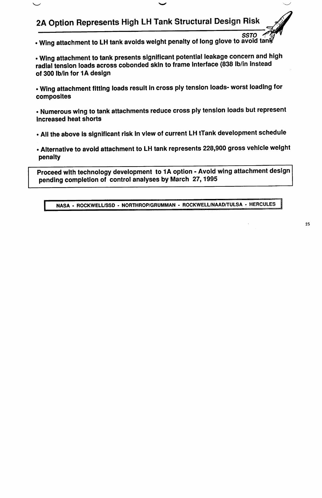
2A Option Represents High LH Tank Structural Design Risk _,J
SSTO
• Wing attachment to LH tank avoids weight penalty of long glove to avoid tant_
• Wing attachment to tank presents significant potential leakage concern and highradial tension loads across cobonded skin to frame interface (838 Ib/in instead
of 300 Ib/in for 1A design
• Wing attachment fitting loads result in cross ply tension loads- worst loading for
composites
• Numerous wing to tank attachments reduce cross ply tension loads but representIncreased heat shorts
• All the above is significant risk in view of current LH tTank development schedule
• Alternative to avoid attachment to LH tank represents 228,900 gross vehicle weight
penalty
Proceed with technology development to 1A option - Avoid wing attachment design
pending completion of control analyses by March 27, 1995
NASA - ROCKWELL/SSD - NORTHROP/GRUMMAN - ROCKWELL/NAAD/TULSA - HERCULES ,I
25

Non-integral Tank May Be Most Likely Design for Strict
Adherence to Debris Impact- Lowest Risk Design __
•i ss oNo option satisfies no penetration probab=l=ty requirement in regime of .99_Current weight penalty of non-integral tank may be negated for strict adherenceto this requirement
Advantages of non-integral design are:
• Non-integral tank- Loss of pressure is not expected to be critical to vehiclesurvival- burst pressure Issue applies to both• Cryogenic Insulation is not exposed to 400 F- Other insulations possible• Avoidance of criticality of Y-joint technology development
Technology development requirements of non-integral tank are enveloped byintegral tank design
Designs to required debris Impact have significant increases in skin thickness -reduced limit stresses, and radial tension loads
I Recommendation.- Do not include debris impact requirement into development Iof hydrogen tank Pursue Investigation of debris impact requirements and Lsolutions
=
NASA - ROCKWELL/SSD -'NORTHROP/GRUMMAN - ROCKWELIJNAAD/TULSA - HERcuLEs" I
26

Conclusions
SSTO
Option 1A ( LH tank forward, Integral tank, payload at midbody) is most suitable
structural arrangement
• Option 1A marginally controllable• Option 2A stable and controllable
Option 2A Wing attachment to composite LH tank has high design risk
Common bulkhead designs represent prohibitive risk
Non Integral tank can be most suitable design for strict adherance to current
debris Impact
NASA - ROCKWELIJSSD - NORTHROP/GRUMMAN - ROCKWELL/NAAD/TULSA - HERCULES I
2?

Development Recommendations
• Proceed with development of integral 1A Hydrogen tank- Development toencompass integral and non-integral LH tank
Above development is also applicable to 3A (with intertank) Hydrogen tankand 1B-1 non-integral tank with short skirts (Avoidance of penetrations)
• Proceed with development of 1A Intertank - Lowest loads provide design withfabrication challenge
• Proceed with development of 1A Wing with supports straddling LO Tank
• Proceed with 1A Conical Shell Thrust Structure - will have highest gimbal forces
• In any future NRA composite LO tank efforts proceed with 1A LO tank developmentbased on wing attachments straddling the LO tank
• Proceed with refinement of 1A Finite Element Model
NASA - ROCKWELL/SSD - NORTHROP/GRUMMAN - ROCKWELL/NAAD/'I'ULSA - HERCULES
28

Development Recommendations - Cont'd
SSTO
Stay with Gr/BMI unpressurized structures
Use of AFR 700 on Intertank, Wing, Wing control surfaces and Tail results inessentially the same gross vehicle weight as Gr/BMI for Space Station mission
Design to 1100 nm polar AOA will increase TPS weight with AFR 700 design
Operations reductions are small because of small reductions in TPS surface area
Use of TMC, and Blackglas protected by CSic TPS, as necessary, representedsignificant vehicle weight increase
CSic TPS repair, and replacement time savings are offset by Increased inspectionand waterproofing hours
All material variations from Gr/BMI with blanket TPS represent TA 2 schedule risk
NASA - ROCKWELL/SSD - NORTHROP/GRUMMAN - ROCKWELL/NAAD/TULSA - HERCULES
29

IJ