Quick Start Guide - Mini Manual
14
IllusionMage Quick Start Guide (Also known as IllusionMage Blender) Modified 2009 Manual was written for IllusionMage – Blender Modif.
-
Upload
george-l-gasby -
Category
Documents
-
view
229 -
download
0
Transcript of Quick Start Guide - Mini Manual

8/3/2019 Quick Start Guide - Mini Manual
http://slidepdf.com/reader/full/quick-start-guide-mini-manual 1/14
Il lusionMageQuick Start Guide
(Also known as IllusionMage Blender)
Modified 2009
Manual was written for IllusionMage – Blender Modif.

8/3/2019 Quick Start Guide - Mini Manual
http://slidepdf.com/reader/full/quick-start-guide-mini-manual 2/14
IllusionMage Blender Mini-Manual
Welcome to the ‘quick-n-dirty’ IllusionMage Blender Manual in pdf format.
This document contains information and instructions to get you on your way withIllusionMage- the 3d modeling/rendering/animation software
Contents
Introduction
Basic editingGetting started with 3DData Blocks The Blenderdata structure BlenderScreensSelectingTransformationsModeling Materials Files3D view manipulation
Adding Objects Mesh editingRendering

8/3/2019 Quick Start Guide - Mini Manual
http://slidepdf.com/reader/full/quick-start-guide-mini-manual 3/14
Introduction
The Object Oriented System
Blender has a strictly object-oriented structure. Every aspect of the 3D world has been organizedin small data blocks. By linking these together, making copies and editing or re-using them, youcan build complex environments with a minimum of memory usage.
The main data blocks Scene This is the ‘canvas’ of the 3D world. It contains the specific rendering information (camera, imageresolution) and the links to Objects. Different Scenes can use the same Objects. Scenes can alsobe linked together to function as a (film) set.
World This block contains sky, stars, exposure, and other environment variables.
Object The basic 3D information block. This contains a position, rotation, size and transformationmatrices. It can be linked to other Objects for hierarchies or deformation. Objects can be ‘empty’(just an axis) or have a link to ObData, the actual 3D information: Mesh, Curve, Lattice, Lamp, etc.Objects can be linked to animation curves (Ipo) and Materials as well.
Mesh This is the triangles and quads mesh data. It contains vertices, faces, and normals. It can have akeyframe block for morphing. It can be linked to Materials.
Curve
Data to be used as Text, Bezier or BSplines and 3D Nurbs Surfaces. It also has a keyframestructure and can be linked to Materials.
Material This data block contains visual properties such as colours, reflectivity and transparency. It can belinked to eight different Texture blocks.
Texture Use images, procedural formulas or plugins to define textures. Can be linked to Material, Lampand World blocks.
Lamp Data to be used for light information, as colours and shadow settings. Can be linked to Textureblocks as well.
Ipo This is the main animation curve system. Ipo blocks can be used by Objects (for movement), butalso by Materials for animated colours.
8/3/2019 Quick Start Guide - Mini Manual
http://slidepdf.com/reader/full/quick-start-guide-mini-manual 4/14
Introduction
Data structure example
e.This Blender screen dump shows a simple Scen
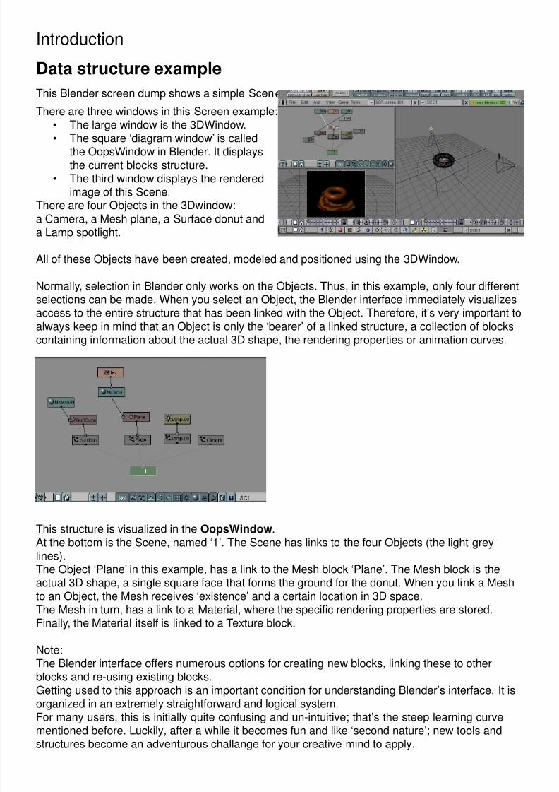
There are three windows in this Screen example:• The large window is the 3DWindow.
• The square ‘diagram window’ is calledthe OopsWindow in Blender. It displaysthe current blocks structure.
• The third window displays the renderedimage of this Scene.
There are four Objects in the 3Dwindow:a Camera, a Mesh plane, a Surface donut anda Lamp spotlight.
All of these Objects have been created, modeled and positioned using the 3DWindow.
Normally, selection in Blender only works on the Objects. Thus, in this example, only four differentselections can be made. When you select an Object, the Blender interface immediately visualizesaccess to the entire structure that has been linked with the Object. Therefore, it’s very important toalways keep in mind that an Object is only the ‘bearer’ of a linked structure, a collection of blockscontaining information about the actual 3D shape, the rendering properties or animation curves.
This structure is visualized in the OopsWindow.At the bottom is the Scene, named ‘1’. The Scene has links to the four Objects (the light grey
lines).The Object ‘Plane’ in this example, has a link to the Mesh block ‘Plane’. The Mesh block is theactual 3D shape, a single square face that forms the ground for the donut. When you link a Meshto an Object, the Mesh receives ‘existence’ and a certain location in 3D space.The Mesh in turn, has a link to a Material, where the specific rendering properties are stored.Finally, the Material itself is linked to a Texture block.
Note:The Blender interface offers numerous options for creating new blocks, linking these to otherblocks and re-using existing blocks.
Getting used to this approach is an important condition for understanding Blender’s interface. It isorganized in an extremely straightforward and logical system.For many users, this is initially quite confusing and un-intuitive; that’s the steep learning curvementioned before. Luckily, after a while it becomes fun and like ‘second nature’; new tools andstructures become an adventurous challange for your creative mind to apply.

8/3/2019 Quick Start Guide - Mini Manual
http://slidepdf.com/reader/full/quick-start-guide-mini-manual 5/14
Introduction
Screens and Windows
.
Each Blender file can have an unlimited number of Screens.
A Screen can be subdivided into windows and each window can be given a certain function.
Each window has a header, which can be at the top or bottom at the user’s discretion. The leftmostbutton displays the window type as an icon.
As usual for any window system, only one window is active at a time, and only this window canreceive the user input. Each window can have a separate mouse and keyboard handling.
To resize a window, simply move the mouse cursor over a window edge. The cursor changesshape. Press and hold LeftMouse to move the edge. Press MiddleMouse to Split the window.Press RightMouse to join two adjacent windows.
At the top of a screen usually the Info window is located. It shows the Scene and Screen nameand - as text - a lot of statistics. If you pull down the window edge, you find the user options. Thesewill be discussed later.
These are the important window types:• 3DWindow. It displays Objects as wireframe, solids or Gouraud shaded.• ButtonsWindow. The visualisation of the specific block types.• IpoWindow. For animation curves and VertexKeys.• OopsWindow. The schematic diagram displaying data blocks.• SequenceWindow. For video editing and post production.• FileWindow. To load or save files.
8/3/2019 Quick Start Guide - Mini Manual
http://slidepdf.com/reader/full/quick-start-guide-mini-manual 6/14
Basic editingBlender is designed as a two-handed system. To minimize mouse strain, almost all commands areavailable both as mouse buttons and as keyboard hot keys. There’s a Toolbox option (pressSPACE) that lists - and can activate - the common hot keys. As a finishing touch, some commandsare available as gestures as well.
Input commands
The Mouse
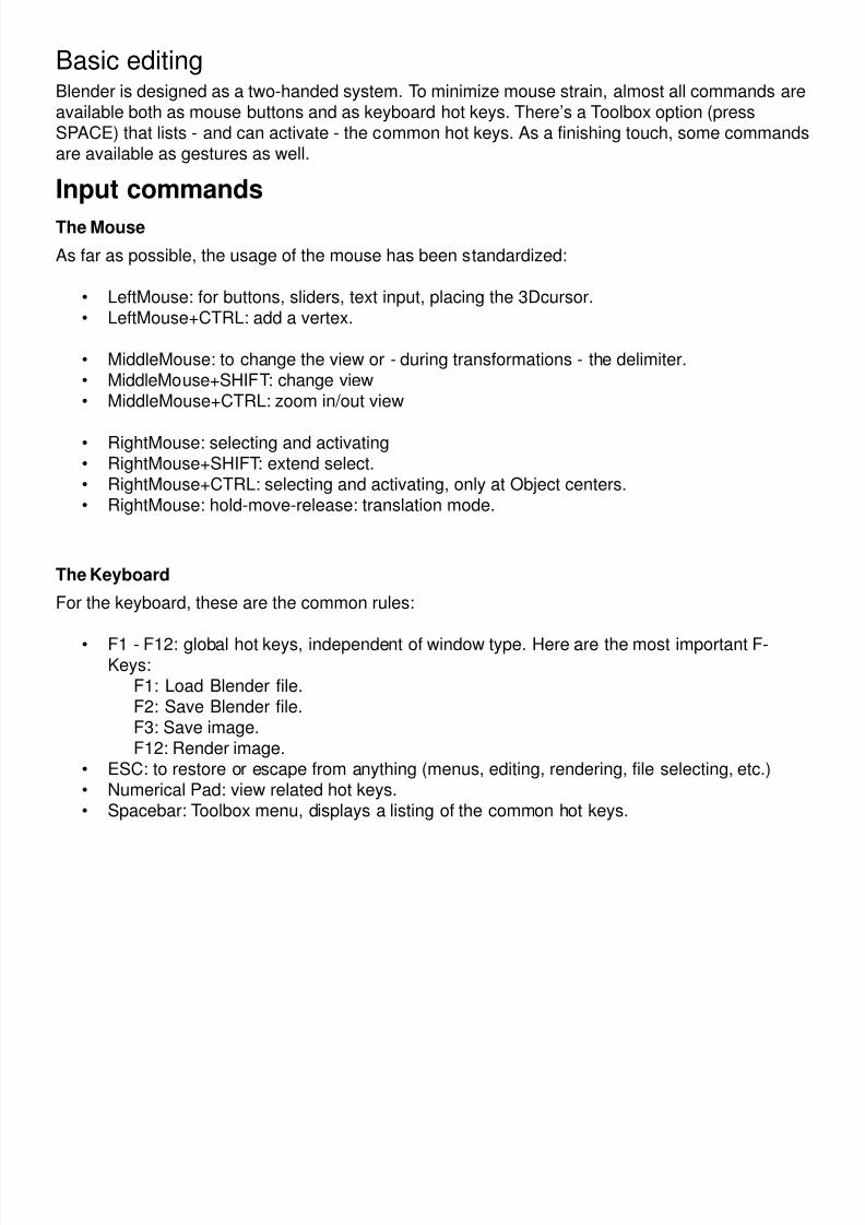
As far as possible, the usage of the mouse has been standardized:
• LeftMouse: for buttons, sliders, text input, placing the 3Dcursor.• LeftMouse+CTRL: add a vertex.
• MiddleMouse: to change the view or - during transformations - the delimiter.• MiddleMouse+SHIFT: change view• MiddleMouse+CTRL: zoom in/out view
• RightMouse: selecting and activating• RightMouse+SHIFT: extend select.• RightMouse+CTRL: selecting and activating, only at Object centers.• RightMouse: hold-move-release: translation mode.
The Keyboard
For the keyboard, these are the common rules:
• F1 - F12: global hot keys, independent of window type. Here are the most important F-Keys:
F1: Load Blender file.F2: Save Blender file.F3: Save image.F12: Render image.
• ESC: to restore or escape from anything (menus, editing, rendering, file selecting, etc.)• Numerical Pad: view related hot keys.• Spacebar: Toolbox menu, displays a listing of the common hot keys.
8/3/2019 Quick Start Guide - Mini Manual
http://slidepdf.com/reader/full/quick-start-guide-mini-manual 7/14
Basic editing
Selecting These are the three methods for selection:
• Selecting with RightMouse always selects (and activates) a single item, it deselectseverything else. However, holding SHIFT while selecting extends the selection.
• Items can be selected with a ‘border’ as well: press BKEY and draw a rectangle with
LeftMouse to select, RightMouse to deselect.• Use the hotkey AKEY to select all or to deselect all items.
Active and Selected
Blender makes a distinction between selected and active.• Only one Object can be active at any given time, for example to allow visualisation of
data in buttons. The active and selected Object is displayed in a lighter colour than otherselected Objects.
• Any number of Objects can be selected at once. Virtually all key commands have an effecton selected Objects.
This is an important distinction because of the non-blocking interface of Blender. Most hot keyactions perform at all selected data. But the ButtonsWindow and IpoWindow can only display thecontents of active data.
Transforms
Moving / rotating / scaling
Most actions in Blender involve moving, rotating or changing size of certain items. Blender offersa wide range of options for this. See the 3DWindow section for a comprehensive list. The optionsare summarised below:
Translation
• GKEY, Grab mode. Move the mouse to translate the selected items, then press LeftMouseor ENTER or SPACE to assign the new location. Press ESC to cancel. Translation is alwayscorrected for the view in the 3Dwindow.
Use the MiddleMouse toggle to limit translation to the X, Y or Z axis. Blender determineswhich axis to use, based on the already initiated movement.
• RightMouse, hold-move. This option allows you to select an Object and ~immediately startGrab mode.
Rotation
• RKEY, Rotation mode. Move the mouse around the rotation centre, then press LeftMouseor ENTER or SPACE to assign the rotation. Press ESC to cancel. Rotation is alwaysperpendicular to the view of the 3DWindow.
Scaling
• SKEY, Scaling mode. Move the mouse from the rotation centre outwards, then pressLeftMouse or ENTER or SPACE to assign the scaling. Use the MiddleMouse toggle to limit
scaling to the X, Y or Z axis. Blender determines the appropriate axis based on the directionof the movement.
8/3/2019 Quick Start Guide - Mini Manual
http://slidepdf.com/reader/full/quick-start-guide-mini-manual 8/14
Basic editing
Objects and EditMode
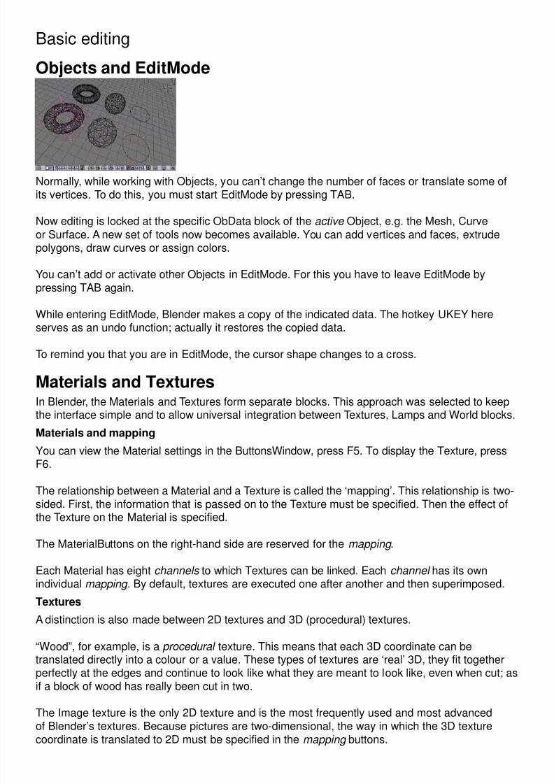
Normally, while working with Objects, you can’t change the number of faces or translate some ofits vertices. To do this, you must start EditMode by pressing TAB.
Now editing is locked at the specific ObData block of the active Object, e.g. the Mesh, Curveor Surface. A new set of tools now becomes available. You can add vertices and faces, extrudepolygons, draw curves or assign colors.
You can’t add or activate other Objects in EditMode. For this you have to leave EditMode bypressing TAB again.
While entering EditMode, Blender makes a copy of the indicated data. The hotkey UKEY hereserves as an undo function; actually it restores the copied data.
To remind you that you are in EditMode, the cursor shape changes to a cross.
Materials and Textures In Blender, the Materials and Textures form separate blocks. This approach was selected to keep
the interface simple and to allow universal integration between Textures, Lamps and World blocks.
Materials and mapping
You can view the Material settings in the ButtonsWindow, press F5. To display the Texture, pressF6.
The relationship between a Material and a Texture is called the ‘mapping’. This relationship is two-sided. First, the information that is passed on to the Texture must be specified. Then the effect ofthe Texture on the Material is specified.
The MaterialButtons on the right-hand side are reserved for the mapping .
Each Material has eight channels to which Textures can be linked. Each channel has its ownindividual mapping . By default, textures are executed one after another and then superimposed.
Textures
A distinction is also made between 2D textures and 3D (procedural) textures.
“Wood”, for example, is a procedural texture. This means that each 3D coordinate can betranslated directly into a colour or a value. These types of textures are ‘real’ 3D, they fit togetherperfectly at the edges and continue to look like what they are meant to look like, even when cut; as
if a block of wood has really been cut in two.
The Image texture is the only 2D texture and is the most frequently used and most advancedof Blender’s textures. Because pictures are two-dimensional, the way in which the 3D texturecoordinate is translated to 2D must be specified in the mapping buttons.
8/3/2019 Quick Start Guide - Mini Manual
http://slidepdf.com/reader/full/quick-start-guide-mini-manual 9/14
Basic editing
Keys and Animation Curves Two methods are normally used in animation software to start a 3D object moving.
• Key Frames.Complete positions are saved for certain time units (frames). An animation is created bymoving an object through them, interpolated fluidly. The animator works from position to
position and can change already created positions.• Motion curves.
Curves can be drawn for each XYZ component for location, rotation and size. These, infact, form the graphs for the movement, with time set out horizontally and the value setout vertically.
Both systems are completely integrated in Blender: in the “Ipo” system. You can create and editIpo’s simply by pressing IKEY in the 3DWindow. A menu appears with a selection of presets.
To visualize the Ipo block, a special window has to be opened. You can change each window intoa IpoWindow with the hotkey SHIFT+F6.
The Ipo block in Blender is universal. It makes no difference whether you are controlling anObject’s movement or the Material’s settings. Once you learn to work with Object Ipos, workingwith other Ipos is obvious.
Saving and loading files Use hotkey F1 to load files, F2 to save files. The active window then changes into a FileWindow.
• Use LeftMouse to activate files or to enter directories.• Press MiddleMouse at a file to load or save it immediately.• Press ENTER to load or save the active file (displayed in the filename button).• Press ESC to cancel the action and restore the previous window type.
The top two buttons in a FileWindow display the directory and the file name respectively. UseLeftMouse to activate a button; press ENTER to assign the text entry to the button.
There are two ways Blender protects the user from software failures and saving errors:• File versions: in the UserMenu (top header, pull down the edge) there’s a “Versions” button.
With this option, before a file is saved, the old file(s) will first be renamed.
For example: the file rt.blend becomes rt.blend1.
• Auto save: with this option, located in the UserMenu as well, a temporary file will be writtenevery ‘x’ minutes. The file name has a unique number (the process id). After successfullyquiting Blender (press QKEY), this file will be renamed as ‘quit.blend’.
Blender has a - sometimes frustrating - preservative memory management.
Deleting an Object for example, doesn’t mean everything that has been linked (Meshes,Materials...) is immediately released in memory. After a few hours of working, you may have a lotof zero-user data blocks.
This feature can be used effectively to ‘undo’ a deletion: use the browse button in the headers to
restore a link.
Data blocks that have zero users are NOT written in files.
Only when a Blender file is loaded, will memory be released and re-organized.
8/3/2019 Quick Start Guide - Mini Manual
http://slidepdf.com/reader/full/quick-start-guide-mini-manual 10/14
Getting started with 3D
Blender start-up
Installation done? Then you’re ready for take off.
Start up Blender as described in the installation section. Start-up should be finished within a fewseconds.
What you see is the contents and window layout of the $HOME/.B.blend file. This file is a regularBlender file and is the default file that loads automatically on start-up. A user can create his owndefault windows, pre-set Materials, models, directories, etc. You can save the user defaults at anytime by pressing CTRL+U.
Part 1 Quick-start guide
3D view manipulation
The largest window is the 3DWindow. It displays a Mesh plane (the square), a Camera and a3Dcursor.
• Click with LeftMouse in the 3DWindow. The 3Dcursor moves to this location. The 3Dcursoris important to indicate where new Objects appear and for rotating and scaling purposes.
• Click, hold and move MiddleMouse in the 3D window. This is the ‘trackball’ style viewrotation. Try this (click-hold-move) at different locations in the window to get used to theTrackBall method.
• Try the same while holding a SHIFT key. SHIFT+MiddleMouse is view translation.• CTRL+MiddleMouse is for zooming in and out.
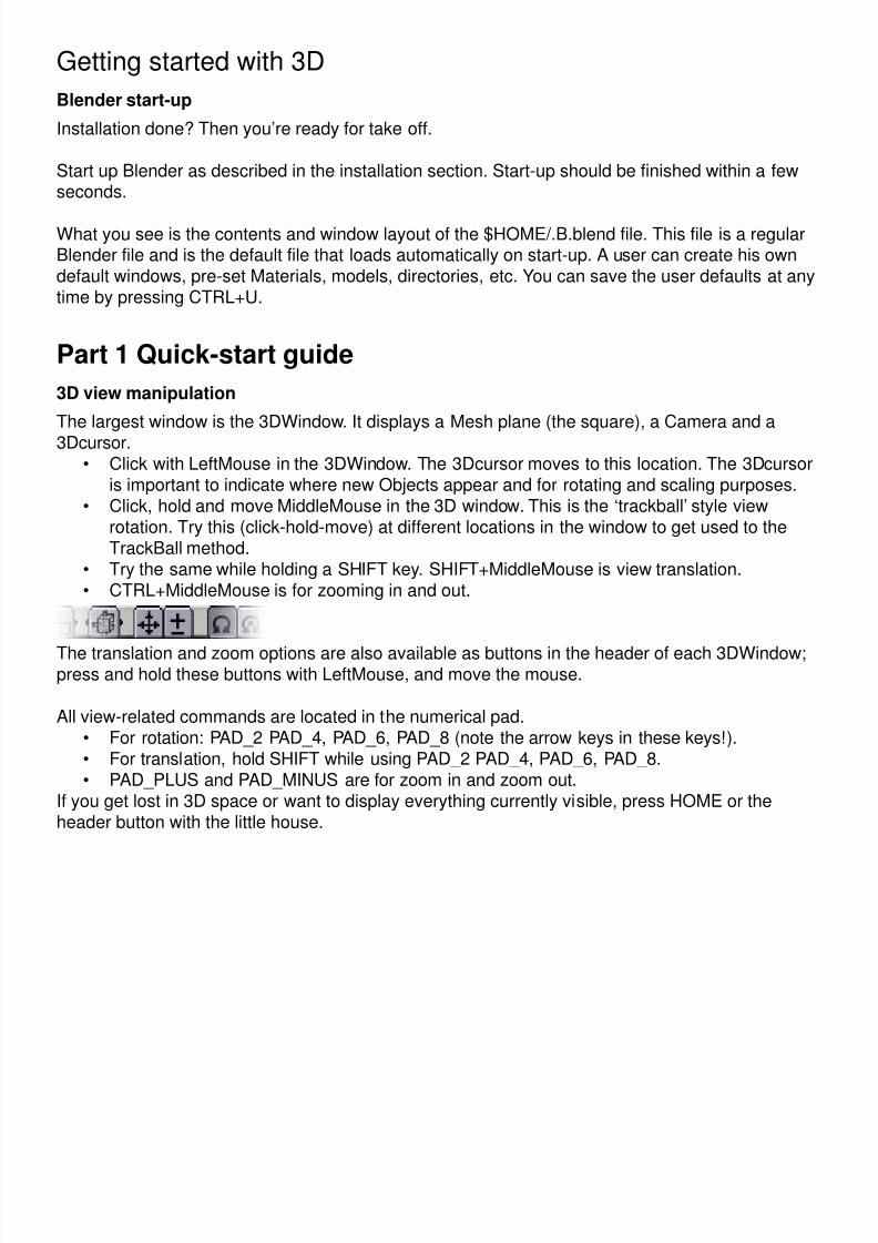
The translation and zoom options are also available as buttons in the header of each 3DWindow;press and hold these buttons with LeftMouse, and move the mouse.
All view-related commands are located in the numerical pad.• For rotation: PAD_2 PAD_4, PAD_6, PAD_8 (note the arrow keys in these keys!).• For translation, hold SHIFT while using PAD_2 PAD_4, PAD_6, PAD_8.• PAD_PLUS and PAD_MINUS are for zoom in and zoom out.
If you get lost in 3D space or want to display everything currently visible, press HOME or theheader button with the little house.

8/3/2019 Quick Start Guide - Mini Manual
http://slidepdf.com/reader/full/quick-start-guide-mini-manual 11/14
Getting started with 3D
View pre-sets
The standard pre-sets ‘Top’, ‘Front’ and ‘Side’ view are also available via the numerical pad• Top view: PAD_7.• Front view: PAD_1.• Side view: PAD_3.
(Note the ‘logical’ location of the keys in the numerical pad).
The view selected is indicated in the header button.
View modes
The 3DWindow has three modes for viewing:• Orthonormal, the basic view mode for modeling.• Perspective. Use the PAD_5 key to toggle Perspective and Orthonormal view mode.• Camera view: press PAD_0. You can get rid of view mode this by invoking any view
command.
Layers
Blender layers are used to organize work and control visibility. Each Object has a layer setting,Scenes and 3DWindows have layers as well, to determine which Objects are visible.
Currently, there are 20 layers available. Press MKEY to move an Object to a certain layer setting.
Part 2 Quick-start guide Adding Objects
Place the 3D cursor one grid unit above the plane. Do this by switching between Top View (PAD_ 7) and Front View (PAD_1).
Press SHIFT+A. This calls up the ToolBox in “Add” mode. Choose the menu item “ADD->Mesh”by pressing LeftMouse. Now the options change to a list of primitives. Choose “IcoSphere”. TheToolBox disappears and a small number requester pops up. Enter a sub-division level by clickingon the left or right side of the button (3 is a nice value). Then press “OK” or ENTER.
Located around the 3Dcursor, a new Object with a Mesh has been added. The Object isautomatically in EditMode, so the vertices and faces of its Mesh can be changed.
We won’t do this now. We leave EditMode by pressing TAB.
Now, we have 3 Objects. You can select these with a RightMouse click, somewhere near thewireframe.
The next step is adding a light. Place the 3D cursor somewhere outside the sphere. Maybe 3-4
grid units away.
Press SHIFT+A. The ToolBox always returns as you previously left it. In this case at: “ADD->IcoSphere”. To go back to the main “ADD” options, click with RightMouse or move the mousecursor to the left side of the ToolBox. Then choose: “ADD->Lamp”.

8/3/2019 Quick Start Guide - Mini Manual
http://slidepdf.com/reader/full/quick-start-guide-mini-manual 12/14
Getting started with 3D
Now a Lamp Object has been added at the 3Dcursor. This type of Object doesn’t have anEditMode.
Press PAD_0 to view from the camera. From this view, Objects can be selected too.
Make a nice composition by using the ‘Grabber’: press GKEY, move the mouse and clickLeftMouse. The Camera can be moved from this view as well.
When you are satisfied, you can render an image: press F12.
Rendering a simple scene like this is fast, but you should notice that it is blocking; the mousecursor changes into a red filled square displaying the current frame number.
The rendered image overlaps the 3D view. To get rid of it: press ESC or F11. To view the imageagain: press F11.
It’s as easy as that!
Material properties
It is time to do something with the ButtonWindow at the bottom of the Screen.
This ButtonWindow has a header at the top (to shorten mouse movements). In this header yousee a row of icon buttons. These buttons indicate the available button groups.
First go to the MaterialButtons. Press the icon button displaying a red sphere.
Then, in the 3DWindow, select with LeftMouse the Object “Plane”. Notice that the Material buttonsalways shows the active Object.
The complete buttons will be explained in a later chapter. Just for now try to locate these sliders:• “R” “G” and “B”: the colour components.• “Ref”: reflectivity.• “Spec”: specular (shine) component• “Hard”: hardness, the specular size.
The ‘Preview’ Render in the MaterialButtons immediately displays the result. Push the little redsphere button above it. This indicates a preview option, it doesn’t affect the actual rendering.
Back in the 3DWIndow, select the Object ‘Sphere’ (using RightMouse). This newly added Objectdoesn’t have a Material yet. To assign a Material we must use the ‘menu’ button in the Buttonsheader:
8/3/2019 Quick Start Guide - Mini Manual
http://slidepdf.com/reader/full/quick-start-guide-mini-manual 13/14
Getting started with 3D
Press and hold this button. Now a menu pops up with 2 choices:
• ‘Material’: you can assign the same Material as already used by ‘Plane’.• ‘ADD NEW”: add a new Material block.
This menu button and its browse functionality is an important Blender feature. You find itthroughout the interface for almost all data types: Textures, Meshes, Worlds, Scenes, etc.
Make a quick rendering to look at the new Material appearances (F12). Note that the ‘Sphere’ stillis rendered faceted. Smoothing by normal interpolation is a not a Material property. Actually, it is aMesh property and can be indicated for each face separately.
Go to the EditButtons (F9) and press the button: “Set Smooth”.
Make a rendering - F12 - to see the result.
Part 3 Quick-start guide
Mesh editing
As mentioned before, the standard editing (such as selecting and translation) can only be donewith Objects. To add faces or to move individual vertices, an Object has to be in EditMode.
You enter and leave EditMode by pressing TAB. The cursor changes shape and selection is nowpossible at individual vertices.
Let’s try this. Clear Blender first (CTRL+X). Select the Plane (RightMouse), and press TAB.
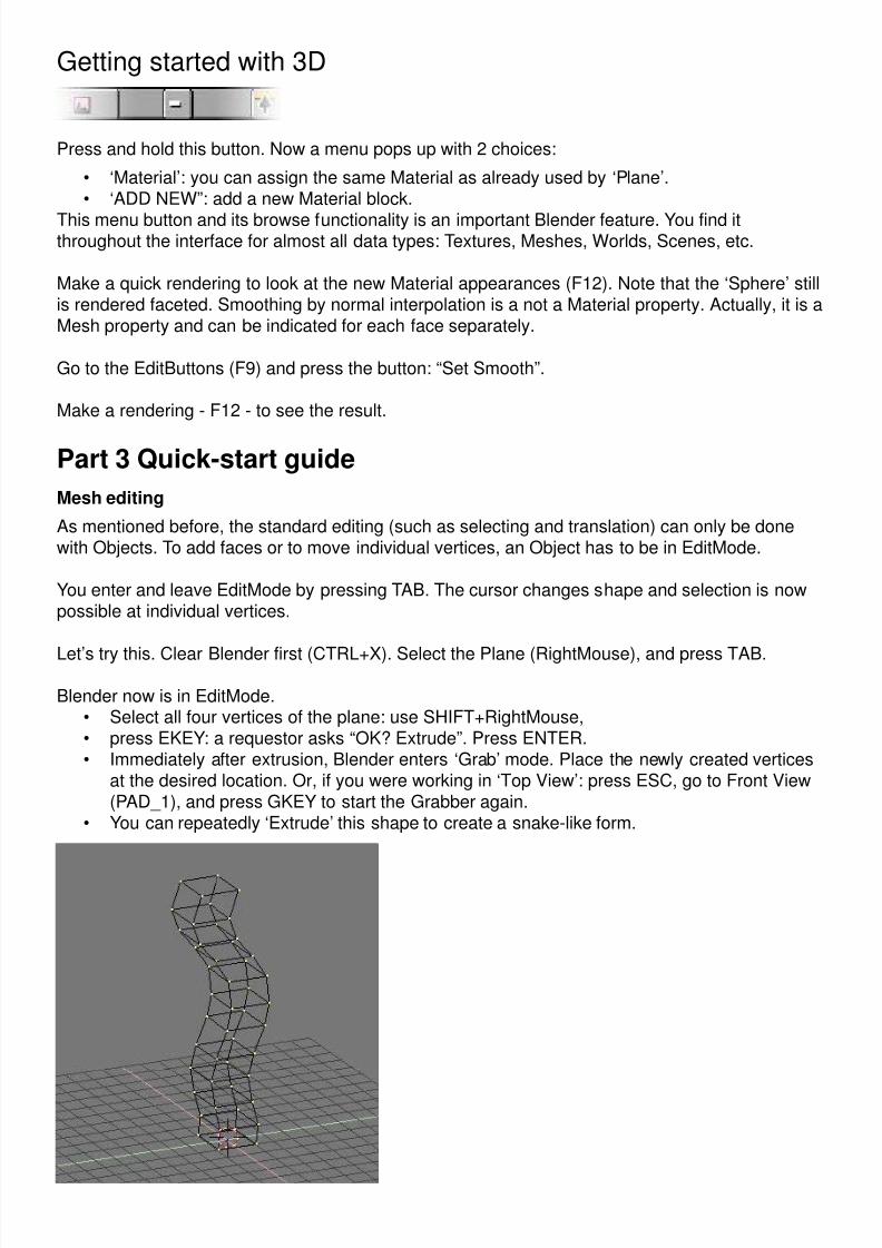
Blender now is in EditMode.• Select all four vertices of the plane: use SHIFT+RightMouse, • press EKEY: a requestor asks “OK? Extrude”. Press ENTER.• Immediately after extrusion, Blender enters ‘Grab’ mode. Place the newly created vertices
at the desired location. Or, if you were working in ‘Top View’: press ESC, go to Front View(PAD_1), and press GKEY to start the Grabber again.
• You can repeatedly ‘Extrude’ this shape to create a snake-like form.
8/3/2019 Quick Start Guide - Mini Manual
http://slidepdf.com/reader/full/quick-start-guide-mini-manual 14/14
Getting started with 3D
Extrusion is a simple and powerful method to create 3D objects. This is how it works:
If the selection contains faces, these are duplicated. At the ‘edge’ of the selection, new facesare created. Blender automatically deletes ‘interior’ faces. For example the Mesh created in theprevious example is completely hollow.
Blender doesn’t have an undo command. To compensate for this, EditMode always saves acopy of the original data. While working in EditMode, the original data can be restored with thecommand UKEY.
In the EditButtons window (press F9) you can find a lot of tools that use extrusion, subdivision, orfilling. These are described more fully in the printed Manual.
Save and Load
To save your work, press F2. The current window changes into a FileSelect. The two large buttonsat the top can be used to enter a directory and a filename respectively. You can exit these buttonswith ENTER.
Press ENTER again to save the file. If the file exists, a requester pops up to confirm a ‘save over’.
A faster way to save without FileSelect is CTRL+W.
To load a Blender file: press F1, move the cursor to a file and press MiddleMouse or clickLeftMouse and press ENTER. A faster method to load without FileSelect is CTRL+O.
Happy Blending!