QUI TRÌNH KIEÅM TRA THÖÛ NGHIEÄM THIEÁT BÒ NAÂNG VAØ ...
179
BỘ LAO ĐỘNG THƯƠNG BINH VÀ XÃ HỘI MINISTRY OF LABOR, INVALID AND SOCIAL AFFAIRS TRUNG TAÂM KIEÅM ÑÒNH KYÕ THUAÄT AN TOAØN KHU VÖÏC 2 CENTER OF INDUSTRIAL SAFETY REGISTRATION ZONE 2 (CISR) QUI TRÌNH KIEÅM TRA THÖÛ NGHIEÄM THIEÁT BÒ NAÂNG VAØ PHÖÔNG TIEÄN, DUÏNG CUÏ MANG TAÛI BOÅ SUNG PROCEDURE FOR LIFTING EQUIPMENT PERIODIC INSPECTION, EXAMINATION AND TESTING Qui trình soá (Procedure No.) : QT 16 Baûn soá (Copy No.): TCVN ISO/ IEC 17020 : 2012 & TCVN ISO/IEC 17025:2007
Transcript of QUI TRÌNH KIEÅM TRA THÖÛ NGHIEÄM THIEÁT BÒ NAÂNG VAØ ...

BỘ LAO ĐỘNG THƯƠNG BINH VÀ XÃ HỘI MINISTRY OF LABOR, INVALID AND SOCIAL AFFAIRS
TRUNG TAÂM KIEÅM ÑÒNH KYÕ THUAÄT AN TOAØN KHU VÖÏC 2 CENTER OF INDUSTRIAL SAFETY REGISTRATION ZONE 2
(CISR)
QUI TRÌNH KIEÅM TRA THÖÛ NGHIEÄM THIEÁT BÒ NAÂNG
VAØ PHÖÔNG TIEÄN, DUÏNG CUÏ MANG TAÛI BOÅ SUNG PROCEDURE FOR LIFTING EQUIPMENT PERIODIC
INSPECTION, EXAMINATION AND TESTING
Qui trình soá (Procedure No.) : QT 16
Baûn soá (Copy No.):
TCVN ISO/ IEC 17020 : 2012 & TCVN ISO/IEC 17025:2007


CENTER OF INDUSTRIAL SAFETY REGISTRATION 2 LIFTING EQUIPMENTS INSPECTION/TESTING PROCEDURE
QT16 – Version 1.3 (07/2018) Pages 2/130 ® Copyright of Center of Industrial Safety Registration zone 2. No Unauthorized Copying of Any Part of This Document
CONTENTS
PART I : COMMON SECTION PAGE
1. Purpose 4
2. Scope 4
3. Personal, Responsibilities 4
4. Referrences 5
5. Terms, Difinitions, Abbreviations 6
6. Testing Equipments 8
7. Testing Place, Weather 9
8.Guideline For Common Inspection/Examination 9
PART 2 : INSPECTION PROCEDURE
QT16-DNV.1 – Inspection/testing Procedure for offshore containers 12
QT16-DNV.2 – Inspection/testing Procedure for Wirerope Slings 19
QT16-DNV.3 – Inspection/testing Procedure for Chain slings 29
QT16-DNV.4 – Inspection/testing Procedure for shackles 37
QT16-DNV.5 – Inspection/testing Procedure for hooks 42
QT16-DNV.6 – Inspection/testing Procedure for Links, Master Links 46
QT16-DNV.7 – Inspection/testing Procedure for Lifting Clamp 50
QT16-DNV.8 – Inspection/testing Procedure for Hammer Locks 54
QT16-DNV.9 – Inspection/testing Procedure for Swivel hoist Ring/Eye bolts 57
QT16-DNV.10 – Inspection/testing Procedure for Eye bolts/Eye Nuts 60
QT16-DNV.11 – Inspection/testing Procedure for TurnBuckles 63
QT16-DNV.12 – Inspection/testing Procedure for Sheave blocks 66
QT16-DNV.13 – Inspection/testing Procedure for Personal Lifting platform/suspended Basket
70

CENTER OF INDUSTRIAL SAFETY REGISTRATION 2 LIFTING EQUIPMENTS INSPECTION/TESTING PROCEDURE
QT16 – Version 1.3 (07/2018) Pages 3/130 ® Copyright of Center of Industrial Safety Registration zone 2. No Unauthorized Copying of Any Part of This Document
QT16-DNV.14 – Inspection/testing Procedure for Lifting beam/spreader/frames
75
QT16-DNV.15 – Inspection/testing Procedure for Manually Operated Hoists 77
QT16-DNV.16 – Inspection/testing Procedure for Electrical/air powered Hoists
84
QT16-DNV.17 – Inspection/testing Procedure for Fibre man made slings 89
QT16-DNV.18 – Inspection/testing Procedure for Bracket (Padeye, lifting Lug)
95
QT16-DNV.19 – Inspection/testing Procedure for drum winch and jaw winch
99
QT16-DNV.20 – Inspection/testing Procedure for Lifting Jack 104
QT16-DNV.21 – Inspection/testing Procedure for Offshore Crane 108
QT16-DNV.22 – Inspection/testing Procedure for DPRS 116
QT16-DNV.23 – Inspection/testing Procedure for Capstan c/w QRH 122
QT16-DNV.24 – Inspection/testing Procedure for Retractable Fall Arrester 126

CENTER OF INDUSTRIAL SAFETY REGISTRATION 2 LIFTING EQUIPMENTS INSPECTION/TESTING PROCEDURE
QT16 – Version 1.3 (07/2018) Pages 4/130 ® Copyright of Center of Industrial Safety Registration zone 2. No Unauthorized Copying of Any Part of This Document
1. PURPOSE
This document provides inspection/testing criteria, procedures and guides to be used when inspecting/ examining for in-service lifting equipments. Following the criteria and procedures contained herein will enable competent personnel to identify lifting equipments that are serviceable and safe for loading and shipping.
2. SCOPE
This document specified procedure and requirements for the inspection/examination/ testing of lifting equipments used on offshore facilities, onshore loading facilities and supply base. Lifting equipment herein are classified as follow:
LIFTING EQUIPMENTS
LIFTING DEVICES
(LIFTING APPLIANCE)
LIFTING GEAR
LIFTED EQUIPMENT RIGGING(RIGGING)
Electric-Air powered Hoist
Chain Hoist Lever Hoist
In-situ lifting beam Jack
Pad eyes
Winch/capstan
Bulk liquid tanks Open freight containers
Closed freight containers Workshops
Laboratories Storage containers
Mini containers Pallets
Open top bins Skips
Baskets Personnel Baskets Gas cylinder racks Spreader frames Equipment skids
Long stock container Modules
Padeyes Section Lifting points & supporting members of
subsea manifolds, Christmas trees & subsea valves
Lifting points and supporting members of machinery
(skids, valves etc)
Wire ropes Wire rope slings
Chain Slings Flat synthetic webbing slings
Polyester round slings Shackles
Hooks/quick release hooks Clamps Rings
Swivels Hammer locks
Sockets Blocks
Stingers
This guideline is intended only to supplement for lifting equipment safety inspection, it does not seek to alter the statutory requirements of lifting equipment safety as well as relative nation safety inspection procedures for lifting equipment.

CENTER OF INDUSTRIAL SAFETY REGISTRATION 2 LIFTING EQUIPMENTS INSPECTION/TESTING PROCEDURE
QT16 – Version 1.3 (07/2018) Pages 5/130 ® Copyright of Center of Industrial Safety Registration zone 2. No Unauthorized Copying of Any Part of This Document
3. PERSONNEL, RESPONSIBILITIES
a) The person, who carried out the inspection/examination/testing for lifting equipment shall be qualified in accordance with CISR training program for inspection/examination/testing for lifting equipment and have the adequate certificate, in valid.
b) The person, who caried out NDT(UT/MT/PT) shall be qualified, in accordance with EN 473, to a minimum of level 2 and have suitable NDT certificate, in valid.
c) The persons, who caried out the inspection/testing shall be ensured all safety conditions before and in all inspection/testing process.
4. REFERENCES BS EN 12079-1:2006 Offshore containers and associated lifting sets –
Part1: Offshore container – Design, Manufacture and marking.
BS EN 12079-3:2006 Offshore containers and associated lifting sets – Part 3: Periodic inspection, Examination and testing.
DNV standard No.2.7-1 Standard for Certification No.2.7-1
EN 970 Non-detructive examination of Fusion welds – Visual examination.
EN 1290 Non-detructive examination of welds – Magnetic particle examination of welds
EN 571-4 Non detructive testing-Penetration testing-Part 1: General principles.
EN ISO 5817a:2003 Welding-Fusion-welded joints in steel, nickel, titanium and their alloys-quality level for imperfections
EN 1291 Non-detructive examination of welds – Magnetic particle testing of welds-Acceptance levels
EN 1289 Non-detructive examination of welds – Penetrant testing of welds-Acceptance levels
TCVN 4244:2005 Vietnamese lifting appliance safety standard
BS EN 13414-3:2003 Wire rope slings-safety
ASME B30.9 Slings
BS EN 818:1996 Shot link chain for lifting purposes
BS EN 13889: 2003 Forged steel shackles for general lifting purposes
BS EN 3551 Alloy steel shackle

CENTER OF INDUSTRIAL SAFETY REGISTRATION 2 LIFTING EQUIPMENTS INSPECTION/TESTING PROCEDURE
QT16 – Version 1.3 (07/2018) Pages 6/130 ® Copyright of Center of Industrial Safety Registration zone 2. No Unauthorized Copying of Any Part of This Document
BSEN 1677-3,5 components for slings -Safety, Forged steel self-locking hooks
BSEN 13155 Cranes – Safety-Non fixed load lifting attachments
BSEN 1677-4 Components for slings – Links grade 8
ASME B30.20 Below the hook lifttng devices
BS 4278 Eyebolt for lifting purpose
BS MA 47 Ships’ cargo blocks
BSEN 14502-1 Suspended basket
BSEN 13001 Crane safety - General design. General principles and requirements
ASME B30.1 Lifting Jack
EN 1494-2000 Mobile or movable jacks and associated lifting equipment
ASME B30.21 Manual operated lever chain hoist
BS EN 13157-2004 Cranes, Safety. Hand powered lifting equipment
ASME B30.11 Monorail Systems and Underhung Cranes
ASME B30.16 Overhead Hoists (Underhung)
BS EN 1492-1 Textile slings- Safety, flat woven webbing slings
BS EN1492-2 Textile slings – Safety round slings, made of man-made fibre for general purpose use
NSL communicating Safety
The International Rigging and lifting hand book
DOE-STD-1090 Hoist and rigging standard of the U.S.Deparment of Energy
AS 1353.1-1997 Flat synthetic-webbing slings
5. TERMS, DEFINITIONS, ABBREVIATIONS
This document used the difinitions, terms and abbreviations mentioned in the applied references and :
- Offshore container (OC): portable unit for repeated use in the transport of goods or equipment handled in open seas to, from, and between fixed and/or floating installations and ships.
- R, Rating : the maximum gross mass of the container including permanent equipment and its cargo, in kg; but excluding the weight of lifting set;
CENTER OF INDUSTRIAL SAFETY REGISTRATION 2 LIFTING EQUIPMENTS INSPECTION/TESTING PROCEDURE
QT16 – Version 1.3 (07/2018) Pages 7/130 ® Copyright of Center of Industrial Safety Registration zone 2. No Unauthorized Copying of Any Part of This Document
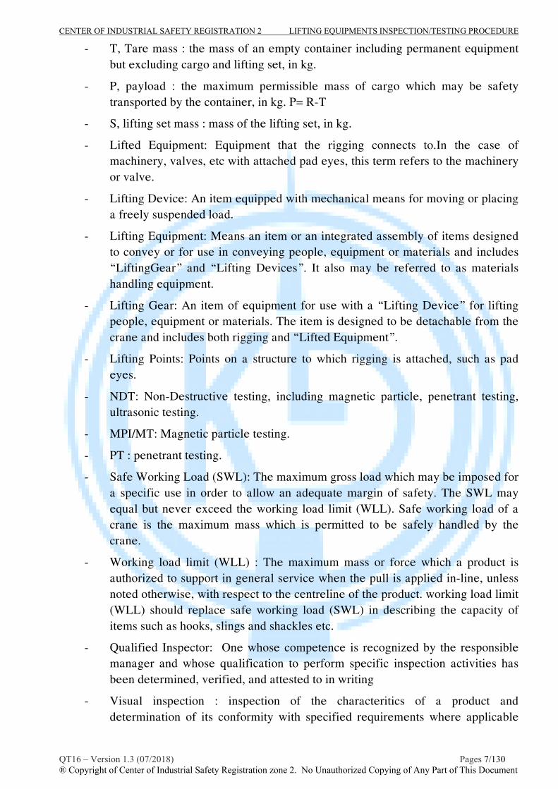
- T, Tare mass : the mass of an empty container including permanent equipment but excluding cargo and lifting set, in kg.
- P, payload : the maximum permissible mass of cargo which may be safety transported by the container, in kg. P= R-T
- S, lifting set mass : mass of the lifting set, in kg.
- Lifted Equipment: Equipment that the rigging connects to.In the case of machinery, valves, etc with attached pad eyes, this term refers to the machinery or valve.
- Lifting Device: An item equipped with mechanical means for moving or placing a freely suspended load.
- Lifting Equipment: Means an item or an integrated assembly of items designed to convey or for use in conveying people, equipment or materials and includes “LiftingGear” and “Lifting Devices”. It also may be referred to as materials handling equipment.
- Lifting Gear: An item of equipment for use with a “Lifting Device” for lifting people, equipment or materials. The item is designed to be detachable from the crane and includes both rigging and “Lifted Equipment”.
- Lifting Points: Points on a structure to which rigging is attached, such as pad eyes.
- NDT: Non-Destructive testing, including magnetic particle, penetrant testing, ultrasonic testing.
- MPI/MT: Magnetic particle testing.
- PT : penetrant testing.
- Safe Working Load (SWL): The maximum gross load which may be imposed for a specific use in order to allow an adequate margin of safety. The SWL may equal but never exceed the working load limit (WLL). Safe working load of a crane is the maximum mass which is permitted to be safely handled by the crane.
- Working load limit (WLL) : The maximum mass or force which a product is authorized to support in general service when the pull is applied in-line, unless noted otherwise, with respect to the centreline of the product. working load limit (WLL) should replace safe working load (SWL) in describing the capacity of items such as hooks, slings and shackles etc.
- Qualified Inspector: One whose competence is recognized by the responsible manager and whose qualification to perform specific inspection activities has been determined, verified, and attested to in writing
- Visual inspection : inspection of the characteritics of a product and determination of its conformity with specified requirements where applicable

CENTER OF INDUSTRIAL SAFETY REGISTRATION 2 LIFTING EQUIPMENTS INSPECTION/TESTING PROCEDURE
QT16 – Version 1.3 (07/2018) Pages 8/130 ® Copyright of Center of Industrial Safety Registration zone 2. No Unauthorized Copying of Any Part of This Document
and based on professional judgement where general requirements apply. Visual inspection may include visual and dimensional.
- Proof load test : The load test to be caried out with the test load requied by the code or standard for the specific equipment.
- Shall : Indicates a mandatory requirement
- Should: Indicates a recommended requirement
6. INSPECTION/TESTING EQUIPMENTS
The equipments, which supported for the inspection/testing include: 6.1. Lifting appliances, lifting gears:
Lifting equipments and lifting gears served to the inspection/testing include but not limit: lifting appliances (cranes, gantry crane, over head crane...), special test rigs; wire rope sling, chain sling, web sling; Shackle, Ring, hooks..; the equipments shall be satisfied requirements as follows: - All equipment is in good working situation, safety. - The structure, capacity and dimension are suitable for the objects to be
inspected/tested (e.g. the minimum capacity shall be at lest 125% requirement capacity/test load for testing).
- The lifting appliances, lifting gear must have the valid inspection/testing certificate.
6.2. Load cell, Dynamometer - Equipments used to measure weight/test force as scales, dynamometers or
loadcells. That equipments is in good working situation, safety; have the valid calibrated certificate.
- The range/capacity of the loadcell ensure that the requirement’s test weight/force is within loadcell capacity/range and the maximum accuracy of calibrated loadcell is 2%.
6.3. Test load (Test mass, test block) - Test load should be secured to evenly distribute inside the container and/or hang
up outside the container (where used, it must have the suitable lifting poin/pad eye for the lifting). The appropriate means of application test load/test mass are:
o Calibrated test blocks o Water bags o Sand bags o Free weights
- Where used, the test block with the identified weight, the test blocks shall be calibrated annually in accordance with acceptable international/nation standard, The measured mass, in kilograms, of each block shall be legibly and durably marked on each block.

CENTER OF INDUSTRIAL SAFETY REGISTRATION 2 LIFTING EQUIPMENTS INSPECTION/TESTING PROCEDURE
QT16 – Version 1.3 (07/2018) Pages 9/130 ® Copyright of Center of Industrial Safety Registration zone 2. No Unauthorized Copying of Any Part of This Document
6.4. NDT equipments and material NDT equipment and material should be in good situation, high quality and have the valid calibrated certificate(equiments), MSDS (material) is in conformity with the CISR’s Material&Testing Equipment control procedure.
7. TESTING PLACE, WEATHER
- The testing site shall have sufficient space to caried out the inspection/testing; hardness, flatness ; ensure the safety distance to the electrical power line is in conformity with the local/nation code ; should be limited/segregated from another working site.
- When caried out the inspection/testing out site, the weather must be in good condition, no rain and wind speed is not exceeding level 4 in beaufort scale (<= 8 m/s).
8. GUIDELINE AND PROCEDURES FOR INSPECTION/EXAMINATION
Each item of lifting equipment shall be examined for a unique identification number and safe working load or working load limit. The corresponding test certificate, proof load certificate, or most resent certificate of thorough examination will be identified and the information checked against what stamped on the equipment.
The client should provide certificate details for each item of lifting equipment at worksite. Inspector may inspect master copies of test certificates for lifting equipment at client’s office by prior arrangement, either before or after an examination program is performed.
Each item of lifting equipment which has been examined and considered suitable for safe continuance service will be certified accordingly. A certificate of examination in the format as appropriate form in this document will be issued by the inspector and approved by CISR manager for all items of lifting equipment which has passed after that.
Each certificate will state in detail the method of examination used. When an item of lifting equipment is found to be defective, one of the following course of action will be pursued:
- Equipment which cannot be repaired in situ will be marked as condemned.
- Equipment which can be repaired will be clearly labeled as unserviceable and a report which will include a brief description of repair required attach to the item. This report will be in the format of “Report of thorough examination of lifting appliance or lifting gear”.
The inspector will prepare a list of all lifting equipment which found to be defective or for which test certificate documentation was incomplete. This list will identify all equipment that has been removed from service, and the list will be given to responsible CISR manager to check prior to send to client.

CENTER OF INDUSTRIAL SAFETY REGISTRATION 2 LIFTING EQUIPMENTS INSPECTION/TESTING PROCEDURE
QT16 – Version 1.3 (07/2018) Pages 10/130 ® Copyright of Center of Industrial Safety Registration zone 2. No Unauthorized Copying of Any Part of This Document
8.1- INSPECTION FLOW CHAT
8.2- DOCUMENTATIONS
The equipment’s owner or user should maintain a record keeping system which contains pertinent information regarding to equipment, record may contain the following:
- Information provided by manufacturer
- Inspection record
- Maintenance record
- Repair record
- Remanufacture record.
8.2.1- Identification
Equipments to be inspeced
Inspection (Visual and
NDT if need)
Proof load Test
Report and issue test Certificate
Return to client with recommend
To “repair”
To “Condemned”
Inspection (Visual and
NDT if need)
Pass
Pass
Fail
Fail
Repairable
NonRepairable

CENTER OF INDUSTRIAL SAFETY REGISTRATION 2 LIFTING EQUIPMENTS INSPECTION/TESTING PROCEDURE
QT16 – Version 1.3 (07/2018) Pages 11/130 ® Copyright of Center of Industrial Safety Registration zone 2. No Unauthorized Copying of Any Part of This Document
The unit serial number provided by manufacturer should be maintained on the equipment and recorded on the equipment record. Identification markings should be provided by owner or user for unidentified equipment which require a maintenance record.
8.2.2- History
Changes in the equipment status which could affect the equipment serviceability or maintenance should be recorded in the equipment record.
8.2.3- Record identification
Entries in the equipment record should include date, names of responsible person involved in the inspection, maintenance, repair, or remanufacture.
8.3. COLOUR CODING
The color code identification is intended to apply for lifting equipment will be appointed by owner or user conformed to each company policy.

CENTER OF INDUSTRIAL SAFETY REGISTRATION 2 LIFTING EQUIPMENTS INSPECTION/TESTING PROCEDURE
QT16 – Version 1.3 (07/2018) Pages 12/130 ® Copyright of Center of Industrial Safety Registration zone 2. No Unauthorized Copying of Any Part of This Document
PROCEDURE No : QT 16-DNV.1
INSPECTION, TESTING PROCEDURE FOR OFFSHORE CONTAINER
A- SCOPE
This procedure provides general guidelines for competent person performing the periodic inspection and load testing of container, cargo baskets, etc. with max. gross mass not exceeded 25,000kg, intended for repeated use, include types:
a) Offshore freight containers like as: - General cargo container : Closed container with doors - Cargo basket: Open top container for general or special cargo - Tank container: container for the transport of dangerous or non-dangerous fluids; - Bulk container: container for the transport of solid in bulk. - Special container: container for the transport of special cargo, e.g. garbage containers, equipments boxes, gas cylinder racks..
b) Offshore service containers like as: Offshore Container built and equipped for the special service task, usually as a temporary installation, e.g. laboratories, workshops, stores, power plant..
c) Waste skip: open or closed offshore container use for storage and removal of waste.
Note: This procedure also applies for some units incorporates permanently installed equipment for lifting and handing and may include equipment for filling, emptying, cooling, heating, etc
The guidance and recommendation will meet the requirements of:
- BS EN 12079:2006 Part 1, 3: Offshore containers and it associated lifting sets.
- DNV CN 2.7-1: DNV standard for certification offshore containers
B- INSPECTION/EXAMINATION
I- Technical Requirements prior to inspection:
The inspector, who caried out the inspection/testing, shall be determined clearly the specifications of the container, e.g max gross mass.. by means of review manufactured documents, last inspection/testing report or re-calculated to check.
II- Inspection procedure:
II.1- Offshore container
- Inspector shall carying out visual inspection, records identified information and specifications of container.
- The Container shall be inspected and assessed in accordance with the requirements as follows :
General visual inspection : The inspection shall be of the exterior and the interior without cargo to ensure that the container is fit for its intended use.

CENTER OF INDUSTRIAL SAFETY REGISTRATION 2 LIFTING EQUIPMENTS INSPECTION/TESTING PROCEDURE
QT16 – Version 1.3 (07/2018) Pages 13/130 ® Copyright of Center of Industrial Safety Registration zone 2. No Unauthorized Copying of Any Part of This Document
All load bearing parts, especially the base structure, shall be inspected. For the containers with fixed equipment, the inspector shall determine whether access to load bearing parts is adequate. The inspection shall be caried out in a situation providing Sufficient lighting and other facilities necessary to allow it to be caried out safety, effectively and the inspection shall be performed in all sides of container.
Markings : The markings and plates shall be checked to ensure that they are adequate and meet the requirements of clause 9 part 1- BS EN 12079:2006 and clause 5- part 3- BS EN 12079:2006 standard (Include Safety marking, Identification Markings, Informations marking and adequate marking for specified kind of container structure, e.g marked the payload of intermediate deck on the inside of the container in a position where it is clearly visible at all times).
The metal structure (primary and secondary structure) : The structure of container shall be visually inspection for corrosion, mechanical damage, injurious deformation. The primary structure shall be in good situation, any steelwork that has suffered significant (greater than 10%) metal loss through corrosion is to be replaced.
Welds : Essential and non-redundant primary structural members shall be welded with full penetration welds. The welds are smooth, without any imperfect of shape, dimensions and other visible cracks.
* Note : When the inspector suspected the crack of welds from visual inspection, he should be required/caried out a suitable NDT examination (MT,PT) as supplemental inspection.
Lifting Points (Pad eye, Pad ear, lashing poins): All padeyes, pad ears, lashing poins shall be thorough visual inspected for corrossion, distorstions, mechanical damages and any other sign of distress or overload.
Recommendations:
The inspector, who carried out the inspection should considered about requirements of BS EN 12079:2006 to inspect and assess as follow:
Note 1 : The pad eye shall have suitable shape, dimensions and palaced in suitable position. The pad eye shall be welded to main frame with full penetration welds.
Note 2: The padeye shall be aligned with the sling to the centre of lift and to permit free movement of the shackle and sling termination without fouling the pad eye, any differrence in the diagonal measurement between lifting poins centres shall not exceed 0,2% of the length of the diagonal, or 5mm, whichever is the greater.
Note 3: The diameter of holes in pad eye shall match the shackle used, clearance between shackle pin and pad eye hole shall not exceed 6% of nominal shackle pin diameter. The tolerence between pad eye thickness (included thickness of cheek plates) and inside width of shackle not exceed 25% of the inside width of shackle.

CENTER OF INDUSTRIAL SAFETY REGISTRATION 2 LIFTING EQUIPMENTS INSPECTION/TESTING PROCEDURE
QT16 – Version 1.3 (07/2018) Pages 14/130 ® Copyright of Center of Industrial Safety Registration zone 2. No Unauthorized Copying of Any Part of This Document
Door closures : Doors, frame, hinges, seals, locks, etc shall be visual inspected and funtionally checked to ensure that they operate in a sastisfactory manner without any undue force being required.
Floors: The floor shall be checked to ensure that it is not deformed and that it shows no signs of distress or overload. Drainage faccilities where fitted, shall be inspected, e.g. Drain holes shall be clear of derbis
Folklift pocket : folk pockets shall be visual inspected from inside corrosion, abration, mechanical damage, injurious deformation (because that are usually not painted inside and may be damaged from folk blades).
* Note 1: the folk pockets should be checked to ensure that all dimension in conformity with the designed and clause 4.4.6 – DNV 2.7-1:2006 requirements, but in any case, the centre distance between pockets pair shall be at least 900mm and not exceed 2050mm.
- NDT examination : In the essential or specified situation, the inspector shall be assigned suitabe NDT examination (MT,PT) as supplemental inspection to detect the cracks, non-continuous imperfect in welds and base metal of pad eye/lifting poins or other force supported point on the steelwork of container.
Structure welds shall be examined as stipulated in table below :
Type of examination
Category of Member Visual Examination Magnetic particle examination (*)
Primary structure : Essential/Non-redundant
100% 100% esspecially for padeyes.
Primary structure : Non-Essential
100% Spot **
Secondary Structure 100% Spot**
* Dye penatrant examination shall be used where magnetic particle examination is not possible.
** Spot means the random examination to the discretion of inspector
NDE methods shall be according to Table 5-2, or to DNV’s Rules for Classification of Ships, Pt.2 Ch.3 Sec.7 or other recognised standards.
The soundness of welded joints shall comply with Table 5-3,or with DNV’s Rules for Classification of Ships, Pt.2 Ch.3 Sec.7 or other recognised standards.

CENTER OF INDUSTRIAL SAFETY REGISTRATION 2 LIFTING EQUIPMENTS INSPECTION/TESTING PROCEDURE
QT16 – Version 1.3 (07/2018) Pages 15/130 ® Copyright of Center of Industrial Safety Registration zone 2. No Unauthorized Copying of Any Part of This Document
II.2 - Lifting set
- The inspection shall be caried out with normally corrected vision, in a situation providing sufficient lighting and other facilities nescesary to allow it to be caried out safety and effectively.
- All of secured lifting set of the container shall be inspected in accordance to relative inspection procedure of CISR and requirement of BS EN 12076 and DNV 2.7.1.
When all the requirement inspections above were assessed with satisfactory, the container and associated lifting sets will be go on the lifting test stage.
III- Lifting Test :
- The inspector should be selected the sets of lifting appliance, loadcell, test weight and lifting gear suitable for specified testing requirements.
- The operator shall be setted up the lifting appliance (or suitable test rig) correctly, safety and suitable for specified testing requirements and put the container/associated lifting sets on the right test position.
- The operator/rigger shall be fitted the slings and other lifting sets in to all pad eyes of container as it’s normal operation condition. The masterling of sling connecting to the hooks of lifting appliance by means of loadcell’s shackle, all fitting shall be corrected and secured. Lift the container by means of hoist of lifting appliance (or hoist of test rig) to check the weight of empty container and it’s associated lifting set through loadcell ( check and determine T).
* Note 1: where the lifting set intended for use with the container is used for the lifting test, care should be taken to ensure that no overloading, distortion, or deformation is included in the lifting set. Should the lifting set normally fitted to the container be used for the lifting test, it should be visually inspected after the loadtest.
* Note 2: The container shall be lifted by a lifting set with an angle to the vertical equal to the design angle.
III.1- Calculation of the requirement weight of added test blocks:
- The inspector shall be calculated to determine the weight of added test block so that the total weights of empty container(T) and test blocks (Pt, testing weight) equal to 2,5 (for all point testing) or 1,5 (for two point testing) multiplied by the rating of maximum gross mass (R) :
+ For all points lifting test :T+ Pt = 2,5x R = 2,5( P+T)
CENTER OF INDUSTRIAL SAFETY REGISTRATION 2 LIFTING EQUIPMENTS INSPECTION/TESTING PROCEDURE
QT16 – Version 1.3 (07/2018) Pages 16/130 ® Copyright of Center of Industrial Safety Registration zone 2. No Unauthorized Copying of Any Part of This Document
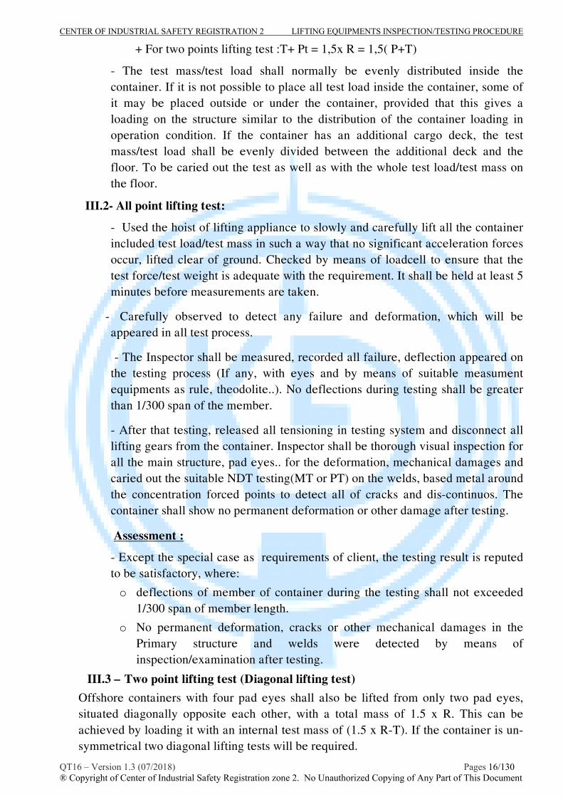
+ For two points lifting test :T+ Pt = 1,5x R = 1,5( P+T)
- The test mass/test load shall normally be evenly distributed inside the container. If it is not possible to place all test load inside the container, some of it may be placed outside or under the container, provided that this gives a loading on the structure similar to the distribution of the container loading in operation condition. If the container has an additional cargo deck, the test mass/test load shall be evenly divided between the additional deck and the floor. To be caried out the test as well as with the whole test load/test mass on the floor.
III.2- All point lifting test:
- Used the hoist of lifting appliance to slowly and carefully lift all the container included test load/test mass in such a way that no significant acceleration forces occur, lifted clear of ground. Checked by means of loadcell to ensure that the test force/test weight is adequate with the requirement. It shall be held at least 5 minutes before measurements are taken.
- Carefully observed to detect any failure and deformation, which will be appeared in all test process.
- The Inspector shall be measured, recorded all failure, deflection appeared on the testing process (If any, with eyes and by means of suitable measument equipments as rule, theodolite..). No deflections during testing shall be greater than 1/300 span of the member.
- After that testing, released all tensioning in testing system and disconnect all lifting gears from the container. Inspector shall be thorough visual inspection for all the main structure, pad eyes.. for the deformation, mechanical damages and caried out the suitable NDT testing(MT or PT) on the welds, based metal around the concentration forced points to detect all of cracks and dis-continuos. The container shall show no permanent deformation or other damage after testing.
Assessment :
- Except the special case as requirements of client, the testing result is reputed to be satisfactory, where:
o deflections of member of container during the testing shall not exceeded 1/300 span of member length.
o No permanent deformation, cracks or other mechanical damages in the Primary structure and welds were detected by means of inspection/examination after testing.
III.3 – Two point lifting test (Diagonal lifting test) Offshore containers with four pad eyes shall also be lifted from only two pad eyes, situated diagonally opposite each other, with a total mass of 1.5 x R. This can be achieved by loading it with an internal test mass of (1.5 x R-T). If the container is un-symmetrical two diagonal lifting tests will be required.

CENTER OF INDUSTRIAL SAFETY REGISTRATION 2 LIFTING EQUIPMENTS INSPECTION/TESTING PROCEDURE
QT16 – Version 1.3 (07/2018) Pages 17/130 ® Copyright of Center of Industrial Safety Registration zone 2. No Unauthorized Copying of Any Part of This Document
After the testing there shall be no significant permanent deformation. * Guidance note: Elastic deformations during lifting should also be observed. The Inspector should ensure that elastic deformations are acceptable.
IV- Schedule of examination and test of offshore containers Containers should be periodically examined and tested as described above according to the schedule based on the assessment of inspector but the interval not exceeding 12 months. The inspector may require other or additional tests and examinations, and dismantling if considered necessary. Note: National authorities may have stricter requirements for periodical inspections. When a lifting test is required, the non-destructive testing and thorough visual examination shall both be carried out after the lifting test.
V- Report the result of inspection/testing :
- The inspector shall be completed and reported the result of inspection/testing in accordance with the form M16.1.1 and issued the certificate in accordance with the form M16.1.2.
- The inspection certificate shall be issued following the CISR’s procedure No. TT09.

CENTER OF INDUSTRIAL SAFETY REGISTRATION 2 LIFTING EQUIPMENTS INSPECTION/TESTING PROCEDURE
QT16 – Version 1.3 (07/2018) Pages 18/130 ® Copyright of Center of Industrial Safety Registration zone 2. No Unauthorized Copying of Any Part of This Document
Example of offshore container :
CENTER OF INDUSTRIAL SAFETY REGISTRATION 2 LIFTING EQUIPMENTS INSPECTION/TESTING PROCEDURE
QT16 – Version 1.3 (07/2018) Pages 19/130 ® Copyright of Center of Industrial Safety Registration zone 2. No Unauthorized Copying of Any Part of This Document
PROCEDURE No : QT 16-DNV.2 INSPECTION, TESTING PROCEDURE FOR WIREROPE SLING
A- SCOPE
This procedure provides general guidelines for competent person performing the periodic
inspection and load testing of wire rope, wire rope sling for general lifting service with diameter of slings are between 8mm to 60mm.
The guidance and recommendation will meet the requirements of :
- BS EN 12079:2006 Part 2, 3: Offshore containers and it associated lifting sets.
- DNV CN 2.7-1: DNV standard for certification offshore containers
- BS EN 13414-1,2,3:2003 : Wire rope slings-safety
- ASME B30.9 : Slings
- TCVN 4244:2005: Vietnamese lifting appliance safety standard.
B- INSPECTION/EXAMINATION/TESTING
I- Technical Requirements prior to inspection:
The inspector, who caried out the inspection/testing, shall be determined clearly the specifications of the wire rope sling, e.g WLL by means of review manufactured documents, last inspection/testing report or re-calculated to check.
II - Inspection/Examination Procedure
- Inspector shall carying out visual inspection, records identified information and specifications of sling in to checklist as M16.2.1 form attached in this procedure.
- The lengths mentioned below shall be measured with a steel tape with 1 mm division. The length of a single leg sling and the length of the individual legs of multi-leg slings shall be measured without load and with the widths of soft eyes being approximately half their length.
- The sling shall be cleaned prior to each inspection because damage may be hidden by dirt or oil. Carefully Visual inspected and dimensioned the condition of the sling in order to identify any obvious damage or deterioration that might affect its use with the requirements as follows :
Formation of eyes:
* Ferrule-secured eye slings: The minimum length of plain rope between the inside ends of ferrules terminating a sling leg shall be 20 times the nominal rope diameter.
* Spliced eye slings : The minimum length of plain rope between the tails of splices shall be at least 15 times the nominal rope diameter.
* Hard eyes : Hard eyes shall be fitted with thimbles conforming to EN 13411-1 * Soft eyes : The peripheral length of a soft eye shall be at least four rope lay
CENTER OF INDUSTRIAL SAFETY REGISTRATION 2 LIFTING EQUIPMENTS INSPECTION/TESTING PROCEDURE
QT16 – Version 1.3 (07/2018) Pages 20/130 ® Copyright of Center of Industrial Safety Registration zone 2. No Unauthorized Copying of Any Part of This Document
lengths. NOTE : A stirrup can be fitted to protect the bearing surface of the soft eye.
* Terminal fittings :
The working load limit of any master link shall be at least equal to that of the sling. The working load limit of any intermediate link fitted to a three-leg or four-leg sling shall be at least equal to 1,6 times the WLL of one of the legs suspended from it.
The working load limit of the lower terminal fitting(s) shall be at least equal to that of the leg(s) to which it is/they are fitted.
The terminal fittings shall be inspected in accordance with relative inspection procedure in this document.
Inspector should considered about some terminal fitting/ferrule defects such as excessive wear, corrosion, distortion, cracks.. to discard use of sling.
Note : In the essential or specified situation, the inspector shall be assigned suitabe NDT examination (MT,PT) as supplemental exmination to detect the cracks, non-continuous imperfect in metal parts.
Rope of sling :
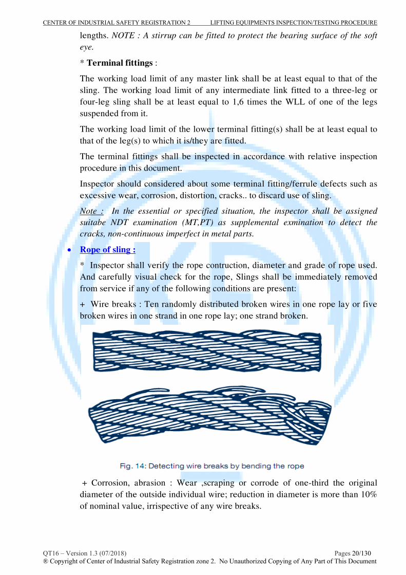
* Inspector shall verify the rope contruction, diameter and grade of rope used. And carefully visual check for the rope, Slings shall be immediately removed from service if any of the following conditions are present:
+ Wire breaks : Ten randomly distributed broken wires in one rope lay or five broken wires in one strand in one rope lay; one strand broken.
+ Corrosion, abrasion : Wear ,scraping or corrode of one-third the original diameter of the outside individual wire; reduction in diameter is more than 10% of nominal value, irrispective of any wire breaks.

CENTER OF INDUSTRIAL SAFETY REGISTRATION 2 LIFTING EQUIPMENTS INSPECTION/TESTING PROCEDURE
QT16 – Version 1.3 (07/2018) Pages 21/130 ® Copyright of Center of Industrial Safety Registration zone 2. No Unauthorized Copying of Any Part of This Document
+ Rope deformation : Inspector should consider about the deformation of rope e.g. Kinking, crushing, birdcaging, or any other damage resulting in distortion of the rope structure. Some discarded criteria as below:
a) Formation of corkscrews : A wire rope must be discarded if the corkscrew formation in the worst affected area has reached a wave height of 1/3 of the rope diameter.
b) Formation of birdcages :When birdcages occur the wire rope must be discarded.
c) Loop formations : A wire rope must be discarded if wire loop formations have considerably changed the rope structure.
d) Local reduction in diameter :A wire rope must be discarded if severe local reductions in diameter occur.
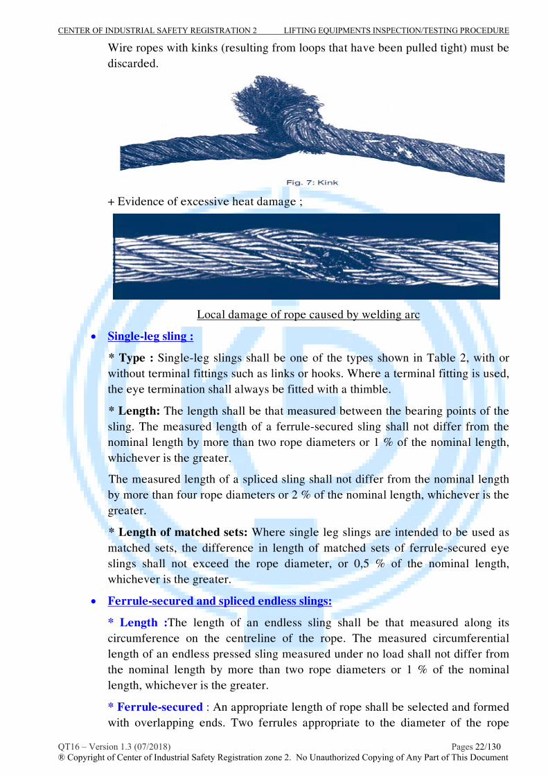
h) Kinks
CENTER OF INDUSTRIAL SAFETY REGISTRATION 2 LIFTING EQUIPMENTS INSPECTION/TESTING PROCEDURE
QT16 – Version 1.3 (07/2018) Pages 22/130 ® Copyright of Center of Industrial Safety Registration zone 2. No Unauthorized Copying of Any Part of This Document
Wire ropes with kinks (resulting from loops that have been pulled tight) must be discarded.
+ Evidence of excessive heat damage ;
Local damage of rope caused by welding arc
Single-leg sling :
* Type : Single-leg slings shall be one of the types shown in Table 2, with or without terminal fittings such as links or hooks. Where a terminal fitting is used, the eye termination shall always be fitted with a thimble.
* Length: The length shall be that measured between the bearing points of the sling. The measured length of a ferrule-secured sling shall not differ from the nominal length by more than two rope diameters or 1 % of the nominal length, whichever is the greater.
The measured length of a spliced sling shall not differ from the nominal length by more than four rope diameters or 2 % of the nominal length, whichever is the greater.
* Length of matched sets: Where single leg slings are intended to be used as matched sets, the difference in length of matched sets of ferrule-secured eye slings shall not exceed the rope diameter, or 0,5 % of the nominal length, whichever is the greater.
Ferrule-secured and spliced endless slings:
* Length :The length of an endless sling shall be that measured along its circumference on the centreline of the rope. The measured circumferential length of an endless pressed sling measured under no load shall not differ from the nominal length by more than two rope diameters or 1 % of the nominal length, whichever is the greater.
* Ferrule-secured : An appropriate length of rope shall be selected and formed with overlapping ends. Two ferrules appropriate to the diameter of the rope

CENTER OF INDUSTRIAL SAFETY REGISTRATION 2 LIFTING EQUIPMENTS INSPECTION/TESTING PROCEDURE
QT16 – Version 1.3 (07/2018) Pages 23/130 ® Copyright of Center of Industrial Safety Registration zone 2. No Unauthorized Copying of Any Part of This Document
shall be pressed in accordance with prEN 13411-3. The adjacent ends of the ferrules shall not be less than three times the length of the ferrule apart after pressing.
* Spliced : The rope shall be formed into a circle such that the two ends overlap by the amount necessary for splicing. Each end shall be spliced back into the main body of the sling. The splicing operation shall be in accordance with EN13411-2.
Multi-leg slings:
* Length : The length shall be that measured between the bearing points of the sling. The measured individual leg lengths shall not differ from the nominal length of the sling by more than two rope diameters or 1 % of the nominal length, whichever is the greater. The difference in length between the individual legs of any multi-leg sling under no load shall not exceed 1,5 times the rope diameter or 0,5 % of the nominal length, whichever is the greater.
* Length of matched sets
The difference in lengths of matched sets of ferrule-secured eye slings shall not exceed the rope diameter, or 0,5 % of the nominal lengths, whichever are the greater.
* Formation of sling
The sling shall comprise two, three or four legs of the types specified in 5.2.1. The rope size type and grade for each leg shall be the same.
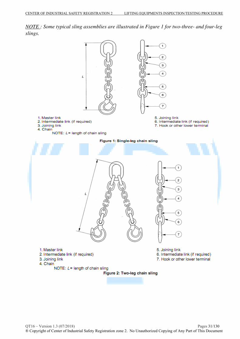
The legs of two-leg slings shall be joined at their upper ends by a master link (see Figure 1). In a three-leg sling, two of the legs shall be joined by a single intermediate master link to the master link, the third leg shall be connected via a second intermediate master link. In a four-leg sling each of the two pairs shall be joined by an intermediate master link to the master link.
Upper eyes shall always be fitted with thimbles, and if lower terminal fittings are used, the eyes shall always be fitted with thimbles. Thimbles shall conform to EN 13411-1.
NOTE : Some typical sling assemblies are illustrated in Figure 1 for two-three- and four-leg slings. The lower terminal fittings can be any of those shown in Table 2.

CENTER OF INDUSTRIAL SAFETY REGISTRATION 2 LIFTING EQUIPMENTS INSPECTION/TESTING PROCEDURE
QT16 – Version 1.3 (07/2018) Pages 24/130 ® Copyright of Center of Industrial Safety Registration zone 2. No Unauthorized Copying of Any Part of This Document

CENTER OF INDUSTRIAL SAFETY REGISTRATION 2 LIFTING EQUIPMENTS INSPECTION/TESTING PROCEDURE
QT16 – Version 1.3 (07/2018) Pages 25/130 ® Copyright of Center of Industrial Safety Registration zone 2. No Unauthorized Copying of Any Part of This Document
III- Proof load test
When all the requirement inspections in the section II above, were assessed with satisfactory, the sling will be go on the lifting test stage.
Personnel in charge of inspection shall decide, with his/her competence and test facilities, the method of proof load testing. He/she can choose either A or B as test method of the mentioned below:
Method A: The wire rope sling set shall be lifted/pulled one (1) time with all legs. based on the sling specification comparing appropriate with table 3 and table 4 of BS EN 13414-1 as below shall indicate the Working Load Limit (in tones) of sling set, therefore test load shall be: 2 x WLL set of sling (for mechanical splice and endless sling); and test load shall be: 1.25 x WLL set of sling (for hand tucked slings- refer to the Part 11.3.2.2 of DOE-STD-1090-2004 for detail).
Note: The angle of legs will be approximately 450 to vertical.
Method B: The wire rope sling set shall be tested by single leg using tension test bed, load test rig or lifting appliance with appropriate test blocks.
- The proof load for mechanical splice single leg slings and endless slings shall be two (2) times the vertical rated load.
- The proof load for multiple leg bridle slings shall be applied to the individual legs and the proof test load shall be either (Only for the sling which used machanical splice) :
+ for 3,4- legs sling : 2 x (WLL All leg s sling )/2,1
+ for 2-legs sling : 2 x (WLL All leg s sling )/1,4
- Any master link to which multiple leg slings are connected shall be proof loaded to two times the force applied by the combined legs.
The wire rope sling shall be carefully loaded in such a way that no significant acceleration forces occur. It shall be held for at least 5 min before reading are taken.
After load test :
After completion of the proof force/load test, and the removal of the force/load, the wire rope or wire rope sling shall be throughout checked for any damage and defect.
- The test shall be considered satisfactory if no cracks, permanent deformation or damage
that would adversely affect the function or safety of the wire rope or wire rope sling is
visible.
- If, satisfactory, the sling set shall be stamped the date of inspection on data plate/sling tag or on ferrule of the sling at the top of sling set.

CENTER OF INDUSTRIAL SAFETY REGISTRATION 2 LIFTING EQUIPMENTS INSPECTION/TESTING PROCEDURE
QT16 – Version 1.3 (07/2018) Pages 26/130 ® Copyright of Center of Industrial Safety Registration zone 2. No Unauthorized Copying of Any Part of This Document

CENTER OF INDUSTRIAL SAFETY REGISTRATION 2 LIFTING EQUIPMENTS INSPECTION/TESTING PROCEDURE
QT16 – Version 1.3 (07/2018) Pages 27/130 ® Copyright of Center of Industrial Safety Registration zone 2. No Unauthorized Copying of Any Part of This Document

CENTER OF INDUSTRIAL SAFETY REGISTRATION 2 LIFTING EQUIPMENTS INSPECTION/TESTING PROCEDURE
QT16 – Version 1.3 (07/2018) Pages 28/130 ® Copyright of Center of Industrial Safety Registration zone 2. No Unauthorized Copying of Any Part of This Document
IV- Schedule of examination and test:
The wire rope sling should be periodically examined and tested as described above according to the schedule based on the assessment of inspector but the interval not exceeding 12 months. The inspector may require other or additional tests and examinations, and dismantling if considered necessary. Note: National authorities may have stricter requirements for periodical inspections.
When the schedule requires a load test, any non-destructive examination and visual inspection shall both be carried out after the load test.
V- Report the result of inspection/testing:
- The inspector shall be completed and reported the result of inspection/testing in accordance with the form M 16.2.1 and issued the inspection/loadtest certificate in accordance with the form M 16.3.2 - The inspection certificate shall be issued in accordance with the CISR’s procedure No. TT09.

CENTER OF INDUSTRIAL SAFETY REGISTRATION 2 LIFTING EQUIPMENTS INSPECTION/TESTING PROCEDURE
QT16 – Version 1.3 (07/2018) Pages 29/130 ® Copyright of Center of Industrial Safety Registration zone 2. No Unauthorized Copying of Any Part of This Document
PROCEDURE No : QT 16-DNV.3 INSPECTION, TESTING PROCEDURE FOR CHAIN SLINGS
A- SCOPE
This procedure provides general guidelines for competent person performing the periodic
inspection and load testing of chain sling for general lifting service with the range of nominal sizes of chain covered by EN 818-2,3 is from 4mm to 45mm..
This guidance and recommendation will meet the requirements of :
- BS EN 12079:2006 Part 2, 3: Offshore containers and it associated lifting sets.
- DNV CN 2.7-1: DNV standard for certification offshore containers
- BS EN 818:1996 : shot link chain for lifting purposes
- ASME B30.9 Chapter 9.1: Alloys steel chain Slings
- TCVN 4244:2005: Vietnamese lifting appliance safety standard.
B- INSPECTION/EXAMINATION/TESTING
I- Technical Requirements prior to inspection:
The inspector, who caried out the inspection/testing, shall be determined clearly the specifications of the chain sling, e.g WLL by means of review manufactured documents, last inspection/testing report or re-calculated to check.
II - Inspection/Examination Procedure
- Inspector shall carying out visual inspection, records identified information and specifications of sling in to checklist as M16.3.1 form attached in this procedure.
- Dimensional: sling should be hung up or stretched out on a level floor in a well-lighted area, remove all twists. Measure the sling length.Multi-leg chain sling, the differences in length between the longest and shortest legs which are nominally the same length shall, when measured under equivalent tension, be not greater than 6 mm for nominal leg lengths up to and including 2 m and not greater than 3 mm/m for nominal leg lengths over 2 m. Discard if a sling has been stretched.
- The sling shall be cleaned prior to each inspection. adequate lighting should be provided and the chain sling should be examined throughout its length to detect any evidence of wear, distortion or external damage. Sling should be withdrawn from service if any of the following are observed:
* The chain sling markings are illegible, ie. Information on the chain sling identification and/or working load limit.
* Distortion of the upper or lower terminals.
* Wear by contact with other objects usually occurs on the outside of the straight portions of the links where it is easily seen and measured. Wear between adjoining links is hidden. The chain should be slack and adjoining links rotated

CENTER OF INDUSTRIAL SAFETY REGISTRATION 2 LIFTING EQUIPMENTS INSPECTION/TESTING PROCEDURE
QT16 – Version 1.3 (07/2018) Pages 30/130 ® Copyright of Center of Industrial Safety Registration zone 2. No Unauthorized Copying of Any Part of This Document
to expose the inner end of each link. Inter link wear, as measured by taking the diameter (see the table below for permissible worn diameter).
* Cuts, nicks, gouges, cracks, excessive corrosion, heat discoloration, bent or distorted links or any other defects.
* Sharp transverse Nicks gouges should be rounded out by grinding and the depth of the gouge or rounded out portion should not exceed values in the table below.
* Distorted or damaged master links, coupling links or attachments; especially those spread in throat opening of hooks. (Please refer EN 1677: components for sling for specific inspection) * If present, latches on hooks should be seat properly, rotate freely, and show no permanent distortion.
Note : concentrated inspection such as below
CENTER OF INDUSTRIAL SAFETY REGISTRATION 2 LIFTING EQUIPMENTS INSPECTION/TESTING PROCEDURE
QT16 – Version 1.3 (07/2018) Pages 31/130 ® Copyright of Center of Industrial Safety Registration zone 2. No Unauthorized Copying of Any Part of This Document
NOTE : Some typical sling assemblies are illustrated in Figure 1 for two-three- and four-leg slings.

CENTER OF INDUSTRIAL SAFETY REGISTRATION 2 LIFTING EQUIPMENTS INSPECTION/TESTING PROCEDURE
QT16 – Version 1.3 (07/2018) Pages 32/130 ® Copyright of Center of Industrial Safety Registration zone 2. No Unauthorized Copying of Any Part of This Document

CENTER OF INDUSTRIAL SAFETY REGISTRATION 2 LIFTING EQUIPMENTS INSPECTION/TESTING PROCEDURE
QT16 – Version 1.3 (07/2018) Pages 33/130 ® Copyright of Center of Industrial Safety Registration zone 2. No Unauthorized Copying of Any Part of This Document
III- Proof load test
When all the requirement inspections in the section II above, were assessed with satisfactory, the sling will be go on the lifting test stage.
Proof test will be caried out by using tension testing machine or lifting appliance with free test weight. Proof load test shall be applied on chain slings at the following circumstance: prior to use, all new, altered, modified, repaired, or periodic inspection ;
Based on the the sling specification comparing appropriate with table 3 of BS EN 818-4 and table 2 of BS EN 818-5 as below, Inspector shall indicated the Working Load Limit (in tones) of sling and rated load of single leg of sling.
Table 3 of BS EN 818-4 : Chain grade 8

CENTER OF INDUSTRIAL SAFETY REGISTRATION 2 LIFTING EQUIPMENTS INSPECTION/TESTING PROCEDURE
QT16 – Version 1.3 (07/2018) Pages 34/130 ® Copyright of Center of Industrial Safety Registration zone 2. No Unauthorized Copying of Any Part of This Document
Table 2 of BS EN 818-5 : Chain grade 4
Personnel in charge of inspection shall decide, with his/her competence and test facilities, the method of proof load testing. He/she can choose either A or B as test method of the mentioned below:
Method A: The chain sling set shall be lifted/pulled one (1) time with all legs. based on the sling specification comparing appropriate with table 3-BS EN 818-4 and table 2 of BS EN 818-4 as above shall indicate the Working Load Limit (in tones) of sling set, therefore test load shall be: 2 x WLL set of sling.
Note: The angle of legs will be approximately 450 to vertical.
Method B: The wire rope sling set shall be tested by single leg using tension test bed, load test rig or lifting appliance with appropriate test blocks.
- The proof load for single leg slings shall be two (2) times the vertical rated load.
- The proof load for multiple leg slings shall be applied to the individual legs and the proof test load shall be either :
+ for 3,4- legs sling : 2 x (WLL All leg s sling )/2,1
CENTER OF INDUSTRIAL SAFETY REGISTRATION 2 LIFTING EQUIPMENTS INSPECTION/TESTING PROCEDURE
QT16 – Version 1.3 (07/2018) Pages 35/130 ® Copyright of Center of Industrial Safety Registration zone 2. No Unauthorized Copying of Any Part of This Document
+ for 2-legs sling : 2 x (WLL All leg s sling )/1,4
- Any master link to which multiple leg slings are connected shall be proof loaded to two times the force applied by the combined legs.
The test load/test force with maximum accuracy +/- 2%, shall be applied to sling or legs without shock. The load shall be applied for a minimum of 5 minutes before measurements are taken.
Note : The inspector should considered to test other parts of chain sling if needed or required, refer to relative inspection procedure in this document for testing.
C. After proof load test
After completion of the proof force test, and the removal of the force, the chain sling shall be throughout examined for any damage and defect.
- The test shall be considered satisfactory if no cracks, permanent deformation or damage
that would adversely affect the function or safety of the chain sling is visible.
- If, satisfactory, the sling set shall be stamped the date of inspection on data plate of sling at the top of sling set and a report/ certificate shall be issuedby the inspector.
IV- Schedule of examination and test:
The Chain sling should be periodically examined and tested as described above according to the schedule based on the assessment of inspector but the interval not exceeding 12 months. The inspector may require other or additional tests and examinations, and dismantling if considered necessary. When the schedule requires a load test, any non-destructive examination and visual inspection shall both be carried out after the load test.
V- Report the result of inspection/testing:
- The inspector shall be completed and reported the result of inspection/testing in accordance with the form M 16.3.1 and issued the inspection/loadtest certificate in accordance with the form M 16.3.2 . - The inspection certificate shall be issued in accordance with the CISR’s procedure No. TT09.

CENTER OF INDUSTRIAL SAFETY REGISTRATION 2 LIFTING EQUIPMENTS INSPECTION/TESTING PROCEDURE
QT16 – Version 1.3 (07/2018) Pages 36/130 ® Copyright of Center of Industrial Safety Registration zone 2. No Unauthorized Copying of Any Part of This Document
PROCEDURE No : QT 16-DNV.4 INSPECTION, TESTING PROCEDURE FOR SHACKLES
A- SCOPE
This procedure provides general guidelines for competent person performing the periodic
inspection and load testing of forged stell shackle for general lifting service with the range of WLL of shackles are from 0,5t to 25t.
The guidance and recommendation will meet the requirements of :
- BS EN 13889: 2003 Forged steel shackles for general lifting purposes.
- BS EN 3551 : Alloy steel shackle
- ASME B30.26-2004: Rigging Hardware
- TCVN 4244:2005: Vietnamese lifting appliance safety standard.
B- INSPECTION/EXAMINATION/TESTING
I- Technical Requirements prior to inspection:
The inspector, who caried out the inspection/testing, shall be determined clearly the specifications of the shackle, e.g WLL by means of review manufactured documents, last inspection/testing report or re-calculated to check.
II - Inspection/Examination Procedure
- Inspector shall carying out visual inspection, records identified information and specifications of shackle in to checklist as M16.4.1 form attached in this procedure.
- The shackle shall be cleaned prior to each inspection because damage may be hidden by dirt, oil, pain. Adequate lighting should be provided to inspection.
- The shackle shall be inspected and assessed in accordance with the requirements as follows :
General visual inspection :
* Marking : The marking shall be legibly and indenlibly marked in a place where the marking will not be removed by use and in the manner that will not impair the mechanical properties. This marking shall include at least the following information placed on the shackle by the manufacturer:
a) working load limit in tonnes e.g. WLL 4,75;
b) the grade number e.g. ‘6’;
c) the manufacturer's name, symbol or code;
d) traceability code.
e) Shackle pins : All shackle pins, 13 mm diameter and above, shall be legibly and indelibly marked with the relevant grade number traceability code and manufacturer's symbol in a manner which will not impair the

CENTER OF INDUSTRIAL SAFETY REGISTRATION 2 LIFTING EQUIPMENTS INSPECTION/TESTING PROCEDURE
QT16 – Version 1.3 (07/2018) Pages 37/130 ® Copyright of Center of Industrial Safety Registration zone 2. No Unauthorized Copying of Any Part of This Document
mechanical properties of the pin. Pins below 13 mm diameter shall be marked with at least either the grade number or the traceability code.
* Visual inspection for mechanical damage and dimensional:
* The inspection shall be all parts of the shackle to ensure that it is fit for its intended use. The shackle shall be fitted with all intended parts and in good condition.
* The main dimensions, shape and special parts shall be in conformity with requirements of applied standards and it’s technical documents. * The principal dimensions of the dee shackle, bow shackle shall conform to Table 2 in which the dimensions are related to the working load limit.
Figure 1 — Dimensions of dee shackles ; bow shackles
Key: 1 Crown ; 2 Body ; 3 Example of screwed pin with eye and collar – type W; 4 Eye ; 5 Bolt type pin with hexagon head, hexagon nut and split cotter pin – type X.

CENTER OF INDUSTRIAL SAFETY REGISTRATION 2 LIFTING EQUIPMENTS INSPECTION/TESTING PROCEDURE
QT16 – Version 1.3 (07/2018) Pages 38/130 ® Copyright of Center of Industrial Safety Registration zone 2. No Unauthorized Copying of Any Part of This Document
The dimensions of the bodies (with the exception of the pin diameters and pin holes) shall be not less than the nominal dimensions and shall not exceed by more than 5% (Refers to tolerances on dimensions of specification in BS 3551).
* Screw threads, Pins, hole diameter shall conform to the requirement in clause 5.2 BS EN 13889-2008 :
* Pins : The collar diameter or width across the flats of the nut shall be at least 1,2D or D+ 3 mm whichever is greater. The outside diameter of the thread shall be the same as the outside diameter of the pin taking into consideration any undercutting of the thread to allow for galvanising or coating.
* The screwed portion of the pin shall be concentric with the main portion. In the case of type W pins, when the pin is fully tightened the length of thread remaining visible between the jaws of the shackle shall not be greater than 1,5 thread pitch.
* In the case of type X pins, when the pin is fully tightened there shall be no thread visible between the jaws of the shackle.
* Hole diameter : The maximum diameter of the unthreaded hole or holes in the body of the shackle shall be either 1,1D or D + 1,5 mm, whichever is greater, where D is the actual pin diameter. Holes in shackle bodies shall be central to the outside of the eyes.
* the shackles must be throughout checked for any of the cracks, distortion, wear, abration and other mechanical as follow:
+ Screw off the pin carrying out checking for wear, distortion or cracking.
+ Check the threaded part for any damage or corrosion.
+ Check the jaw of shackle for any open up.
+ Check the saddle region of the shackle for wear, or evidence of overload.

CENTER OF INDUSTRIAL SAFETY REGISTRATION 2 LIFTING EQUIPMENTS INSPECTION/TESTING PROCEDURE
QT16 – Version 1.3 (07/2018) Pages 39/130 ® Copyright of Center of Industrial Safety Registration zone 2. No Unauthorized Copying of Any Part of This Document
* NDT examination :
Bodies and pins of shackle shall be subjected to magnetic particle or dye penetrant examination in accordance with EN 10228-1 or EN 10228-2 respectively. Testing shall be carried out by a competent person and a distinction shall be made between indications parallel to the contour of the body or pin (see Figure 4 - labelled P) and indications transverse to the contour of the body or pin (see Figure 4 - labelled T)
Indications in the pin head in either direction are permitted.
Pins showing transverse indications shall be rejected and shall not be reworked.
Bodies showing transverse indications shall be rejected. Pins or bodies showing parallel indications shall be rejected.
III- Proof load test
Each shackle, after the throughout check, shall be subject to a proof load test at the centre of the pin equal to 200% of the rated capacity (Test load = 2 x SWL).The shackle shall hold the test load for a minimum 5 minutes without showing permanent deformation or breaking.
After load test, the shackle shall be thoroughly examined (include MT/PT if needed) to ensure that are free from visible flaw, deformation or other defect.
IV- Schedule of examination and test:
The shackle shall be periodically visual inspected, MT/PT examined with interval not exceeding 12 months.
Periodic Load test should be caried out in accordance with recommendation of inspector or client requirements.
When the schedule requires a load test, any non-destructive examination and visual inspection shall both be carried out after the load test.

CENTER OF INDUSTRIAL SAFETY REGISTRATION 2 LIFTING EQUIPMENTS INSPECTION/TESTING PROCEDURE
QT16 – Version 1.3 (07/2018) Pages 40/130 ® Copyright of Center of Industrial Safety Registration zone 2. No Unauthorized Copying of Any Part of This Document
V- Report the result of inspection/testing:
- The inspector shall be completed and reported the result of inspection/testing in accordance with the form M16.4.1 and issued the inspection/loadtest certificate in accordance with the form M16.3.2. - The inspection certificate shall be issued in accordance with the CISR’s procedure No. TT09.

CENTER OF INDUSTRIAL SAFETY REGISTRATION 2 LIFTING EQUIPMENTS INSPECTION/TESTING PROCEDURE
QT16 – Version 1.3 (07/2018) Pages 41/130 ® Copyright of Center of Industrial Safety Registration zone 2. No Unauthorized Copying of Any Part of This Document
PROCEDURE No : QT 16-DNV.5 INSPECTION, TESTING PROCEDURE FOR HOOKS
A- SCOPE
This procedure provides general guidelines for competent person performing periodic inspection and load testing services for lifting hooks with WLL up to 31.5t complying with standard and conde:
+ BSEN 1677-3,5: components for slings , Forged steel lifting hook with latch and eye ;
+ BSEN 13155, Cranes – Safety-Non fixed load lifting attachments;
+ ASME B30.10- Hooks.
B- INSPECTION/EXAMINATION/TESTING
I- Technical Requirements prior to inspection:
The inspector, who caried out the inspection/testing, shall be determined clearly the specifications of the hooks, e.g WLL by means of review manufactured documents, last inspection/testing report or re-calculated to check.
II - Inspection/Examination Procedure
- Inspector shall carying out visual inspection, records identified information and specifications of hook in to checklist as M16.5.1 form attached in this procedure.
- The hooks shall be cleaned prior to each inspection because damage may be hidden by dirt, oil, pain. Adequate lighting should be provided to inspection.
- A qualified inspector shall examine deficiencies and determine whether they constitute a safety hazard. Hooks having any of the following conditions shall be removed from service until repaired or replaced:
* Un-identification: Check the identification of the hook and SWL if it matches to the chain, wire rope, or other suspension members to which they are attached.
* Defects: Check load bearing point, the neck and eye of the hook for any wear, nick, gouge, or cracks.
* Deformation – any bending or twisting exceeding 10degrees from the plane of the unbent hook.
* Damage from chemicals
* Damage, engagement, or malfunction of latch(if provided)
* Evidence of heat damage
* Throat opening – any distortion causing an increase in throat opening exceeding 15%
* Wear – any wear exceeding 10% of the original section dimension of the hook or its load pin.
Safety Latch or self locking component
* Inability to lock: any self locking that does not lock
* Inoperative latch: any latch that does not close the hook’s throat.

CENTER OF INDUSTRIAL SAFETY REGISTRATION 2 LIFTING EQUIPMENTS INSPECTION/TESTING PROCEDURE
QT16 – Version 1.3 (07/2018) Pages 42/130 ® Copyright of Center of Industrial Safety Registration zone 2. No Unauthorized Copying of Any Part of This Document
* Ensure that the latch pin is free from wear, indicated by excessive play.
* Ensure the gap between hook and latch is sufficiently small to prevent load displacement.
* Check that latch mechanism is free to operate.
* NDT examination :
Bodies of hook shall be subjected to magnetic particle or dye penetrant examination in accordance with EN 10228-1 or EN 10228-2(or ASTM E-709 or ASTM E-165) respectively to inspect for surface intersecting discontinuities.
A designated person shall document and resolve the following relevant indications:
a. Arc strikes (welding or electrical).
b. Surface intersecting discontinuities 0.25 in. long or longer.
Note : DISCONTINUITY REMOVAL

CENTER OF INDUSTRIAL SAFETY REGISTRATION 2 LIFTING EQUIPMENTS INSPECTION/TESTING PROCEDURE
QT16 – Version 1.3 (07/2018) Pages 43/130 ® Copyright of Center of Industrial Safety Registration zone 2. No Unauthorized Copying of Any Part of This Document
a. Two directions of discontinuity, “P” and “T,” are shown on Figures below.Discontinuity “P” parallels the contour of the hook, is considered nonserious, and does not require removal. Discontinuity “T,” on the other hand, is transverse to the contour of the hook and is more serious; when occurring in zones B, C, or D, discontinuity “T” may reduce the longevity of the hook.
b. Discontinuities may be removed by grinding longitudinally following the contour of the hook to produce a smooth, gently undulating surface. In zones B and D, such grinding shall not reduce the original hook dimension by more than 10 percent. Such a reduction will not affect the working load limit rating or the ultimate load rating of the hook. In zone C, grinding shall not reduce the original dimension by more than 5 percent.
c. Under normal and proper application, zone A is an unstressed zone. Therefore, it is not required that discontinuities in that zone be ground out.
d. The hook shall be reexamined by performing an NDT after grinding to verify removal of relevant discontinuities
Eye hook
III- Proof load test
Each shackle, after the throughout check, shall be subject to a proof load test at the centre of the pin equal to 200% of the rated capacity (Test load = 2 x SWL).The shackle shall hold the test load for a minimum 5 minutes without showing permanent deformation or breaking.
After load test, the shackle shall be thoroughly examined (include MT/PT if needed) to ensure that are free from visible flaw, deformation or other defect.
IV- Schedule of examination and test:
The hook shall be periodically visual inspected, MT/PT examined with interval not exceeding 12 months (recommendation are 6 months ).
Periodic Load test should be caried out in accordance with recommendation of inspector or client requirements.

CENTER OF INDUSTRIAL SAFETY REGISTRATION 2 LIFTING EQUIPMENTS INSPECTION/TESTING PROCEDURE
QT16 – Version 1.3 (07/2018) Pages 44/130 ® Copyright of Center of Industrial Safety Registration zone 2. No Unauthorized Copying of Any Part of This Document
When the schedule requires a load test, any non-destructive examination and visual inspection shall both be carried out after the load test.
V- Report the result of inspection/testing:
- The inspector shall be completed and reported the result of inspection/testing in accordance with the form M16.5.1 “ inspection/load test report” and issued the inspection/loadtest certificate in accordance with the form M16.3.2 . - The inspection certificate shall be issued in accordance with the CISR’s procedure No. TT09.

CENTER OF INDUSTRIAL SAFETY REGISTRATION 2 LIFTING EQUIPMENTS INSPECTION/TESTING PROCEDURE
QT16 – Version 1.3 (07/2018) Pages 45/130 ® Copyright of Center of Industrial Safety Registration zone 2. No Unauthorized Copying of Any Part of This Document
PROCEDURE No : QT 16-DNV.6 INSPECTION, TESTING PROCEDURE FOR
MASTER LINKS, MASTER LINKS ASSEMBLY, RINGS
A- SCOPE
This procedure provides general guidelines for competent person performing periodic links, rings safety inspection and load testing services complying with BSEN 1677-4 Components for slings – Links grade 8; DOE-STD-1090-2001 Hoisting and Rigging.
B- INSPECTION/EXAMINATION/TESTING
I- Technical Requirements prior to inspection:
The inspector, who caried out the inspection/testing, shall be determined clearly the specifications of the links, link assembly, e.g WLL by means of review manufactured documents, last inspection/testing report or re-calculated to check.
II - Inspection/Examination Procedure
- Inspector shall carying out visual inspection, records identified information and specifications of links in to checklist as M16.6.1 form attached in this procedure.
- The links shall be cleaned prior to each inspection because damage may be hidden by dirt, oil, pain. Adequate lighting should be provided to inspection.
- Links and rings are usually designed and manufactured as a part of the lifting hardware for a specific purpose, such as the peak link on multiple leg slings. However, the rings and links may also be found on the load attachment and of slings. Therefore, the examination of links, master links shall be followed with sling set to which they are attached.
- A qualified inspector shall examine deficiencies and determine whether they constitute a safety hazard. links having any of the following conditions shall be removed from service until repaired or replaced:
* Un-identification: Check the identification of the link and SWL if it matches to the chain,wire rope, or other suspension members to which they are attached.
* Marking: Each link, master link or master link assembly shall be legibly and indelibly marked in a place where the marking will not be removed by use and in a manner that will not impair the mechanical properties. The marking shall include at least the following information.
a) the manufacturer’s product code;
b) The grade number ‘8’;
c) The manufacturer’s name, symbol or mark;
d) The traceability code. .
* Defects: Check load bearing point, the body of the link for any wear, nick, gouge, or cracks.
* Deformation – any bending or twisting exceeding 10degrees from the plane of the unbent link.

CENTER OF INDUSTRIAL SAFETY REGISTRATION 2 LIFTING EQUIPMENTS INSPECTION/TESTING PROCEDURE
QT16 – Version 1.3 (07/2018) Pages 46/130 ® Copyright of Center of Industrial Safety Registration zone 2. No Unauthorized Copying of Any Part of This Document
* Damage from chemicals
* Evidence of heat damage, distortion.
* Wear – any wear exceeding 10% of the original section dimension
* Welded links : The steel in the length affected by welding shall not be displaced at any point so as to undercut the contours of the link. The weld shall be smoothly finished all round. The length affected by welding shall not extend by more than 0,6 of the material diameter to either side of the centre of the weld.
If the link has a flattened section this shall be on the leg of the link opposite to the weld.
Note : concentrated inspection such as below

CENTER OF INDUSTRIAL SAFETY REGISTRATION 2 LIFTING EQUIPMENTS INSPECTION/TESTING PROCEDURE
QT16 – Version 1.3 (07/2018) Pages 47/130 ® Copyright of Center of Industrial Safety Registration zone 2. No Unauthorized Copying of Any Part of This Document
Typical links, link assambly types :
Master link assembly Master link Connecting link
* NDT examination :
Body and weld of links shall be subjected to magnetic particle or dye penetrant examination in accordance with EN 10228-1 or EN 10228-2(or ASTM E-709 or ASTM E-165) respectively to inspect for surface intersecting discontinuities.

CENTER OF INDUSTRIAL SAFETY REGISTRATION 2 LIFTING EQUIPMENTS INSPECTION/TESTING PROCEDURE
QT16 – Version 1.3 (07/2018) Pages 48/130 ® Copyright of Center of Industrial Safety Registration zone 2. No Unauthorized Copying of Any Part of This Document
Indications greater than 2 mm in length shall not be permitted in areas of the link subjected to tensile stresses, in all foreseeable service conditions.
III- Proof load test
Each master link, after the throughout check, shall be subject to a proof load test.
The test equipment used shall apply a force at least equal to the force calculated by multiplying the appropriate it WLL by a factor of 2,5 (see table 5-EN 1677-4-2008 for the WLL of link grade 8 below for reference).the force/load shall be held for 5 minutes.
After removal of the force, there shall be no visible defect such as break, crack and deformation, and the dimensions shall be within the tolerances specified on the manufacturer’s document.
IV- Schedule of examination and test:
The link shall be periodically visual inspected, MT/PT examined with interval not exceeding 12 months (recommendation are 6 months ) such as the schedule inspection of it relevant lifting sling.
Periodic Load test should be caried out in accordance with recommendation of inspector or client requirements.

CENTER OF INDUSTRIAL SAFETY REGISTRATION 2 LIFTING EQUIPMENTS INSPECTION/TESTING PROCEDURE
QT16 – Version 1.3 (07/2018) Pages 49/130 ® Copyright of Center of Industrial Safety Registration zone 2. No Unauthorized Copying of Any Part of This Document
When the schedule requires a load test, any non-destructive examination and visual inspection shall both be carried out after the load test.
V- Report the result of inspection/testing:
- The inspector shall be completed and reported the result of inspection/testing in accordance with the form M 16.6.1 and issued the inspection/loadtest certificate in accordance with the form M16.3.2 . - The inspection certificate shall be issued in accordance with the CISR’s procedure No. TT09.

CENTER OF INDUSTRIAL SAFETY REGISTRATION 2 LIFTING EQUIPMENTS INSPECTION/TESTING PROCEDURE
QT16 – Version 1.3 (07/2018) Pages 50/130 ® Copyright of Center of Industrial Safety Registration zone 2. No Unauthorized Copying of Any Part of This Document
PROCEDURE No : QT 16-DNV.7 INSPECTION, TESTING PROCEDURE FOR
PLATE CLAMPS AND BEAM CLAMPS
A- SCOPE
This part provides general guidelines for competent person performing periodic beam clamp, plate clamp inspection and load testing services to ensure that it is capable of performing the it intended function and fit for use.
The guidance and recommendation will meet the requirements of :
- Manufacturer Recommendation
- The International Rigging and lifting hand book (NSL communicating Safety).
- BSEN 13155 – Non-fixed load fitting attachments
- ASME B30.20- Below the hook lifting devices
- DOE-STD-1090-2004 chapter 14– Below the hook lifting devices
- TCVN 4244:2005: Vietnamese lifting appliance safety standard.
B- INSPECTION/EXAMINATION/TESTING
I- Technical Requirements prior to inspection:
The inspector, who caried out the inspection/testing, shall be determined clearly the specifications of the clamps, e.g WLL, it functions.. by means of review manufactured documents, last inspection/testing report or re-calculated to check.
II - Inspection/Examination Procedure
- Inspector shall carying out visual inspection, records identified information and specifications of shackle in to checklist as M16.7.1 form attached in this procedure.
- The clamps shall be cleaned prior to each inspection because damage may be hidden by dirt, oil, pain. Adequate lighting should be provided to inspection.
- A qualified inspector shall examine deficiencies and determine whether they constitute a safety hazard. Carefully inspected for as requirement below:
* Identification: Check the identification of the clamp and it rated capacity (
Marking: The minimum rated capacity of each clamp shall be metal die stamped,

CENTER OF INDUSTRIAL SAFETY REGISTRATION 2 LIFTING EQUIPMENTS INSPECTION/TESTING PROCEDURE
QT16 – Version 1.3 (07/2018) Pages 51/130 ® Copyright of Center of Industrial Safety Registration zone 2. No Unauthorized Copying of Any Part of This Document
engraved, or embossed in plain view on each clamp. Marking shall be legible at a distance of ten feet and shall remain legible throughout the life of the equipment.)
* Body or frame. The body or frame shall have jaws of unequal length, the shorter jaw being on the side opposite the cam grip in order to facilitate the entrance of steel plates between the jaws. The shorter jaw shall be recessed or other means shall be provided for a positive support of the gripping pad. The lever of the safety lock shall be located within the body or frame, or mounted externally. All other working parts, with the exception of the lifting shackle, shall be constructed within the body or frame.
* Secured attachment shackle, ring, link, chain : carefully examined with requirements of relevant inspection procedure shown on this document.
* Cam grip. The plate gripping surfaces of the cam grips shall have serrations and shall be hardened to a minimum Rockwell “C” hardness reading of 50.
* Gripping pad. The plate gripping surface of the gripping pad shall be serrated. The serrations shall be of a shape and depth to assure a positive grip. Means shall be provided to allow the pad to swivel (rotate) in any direction that contributes to alignment of the clamp with the direction of pull. The entire gripping pad or the serrations thereon shall be hardened to a minimum Rockwell “C” hardness reading of 50.
* Safety lock. The safety lock mechanism shall be of such design that when the lever is in the lock-closed position, the cam grip shall be locked onto a steel plate both with and without tension being applied. Before a suspended steel plate is lowered to rest in an upright plate rack, the actuating lever is moved to a neutral position by the rigger. When the steel plate is lowered to rest (causing a complete release of lifting tension), the actuating lever automatically moves to the lock-open position. In the lock-open position, the cam grip shall be locked in an open position. The clamp may then be raised from the steel plate. Means shall be provided for attachment of a pull cord to the lever.
* Painting. Each clamp shall be painted with high-visibility paint in accordance with the manufacturer’s standard practice.
* Checked for functional and defects: Check load bearing point, the body of the clamp for any wear, nick, gouge, deformation, cracks or other machanical damage and operating functions as follow :
+ Horizontal Clamps:
1. Examine hook ring and lock for wear/stretch in crown of link.
2. Check lateral movement (if any) of hook ring on load bolt connection to serrated
jaws/rocker arms as excessive movement could indicate wear/distortion.
3. Check lateral movement (if any) of serrated jaws/rocker arms on load bolt connection to main body as excessive movement could indicate wear/distortion.
4. Examine the serrations on the jaws or swivel toe and check for wear deformity.
5. Where a toe is fitted, check for lateral movement (if any) of swivel toe on load bolt
connection to rocker arms as excessive movement could indicate wear/distortion.
+ Vertical Clamps:
1. Examine hook ring and check for wear/distortion in the crown of ring.
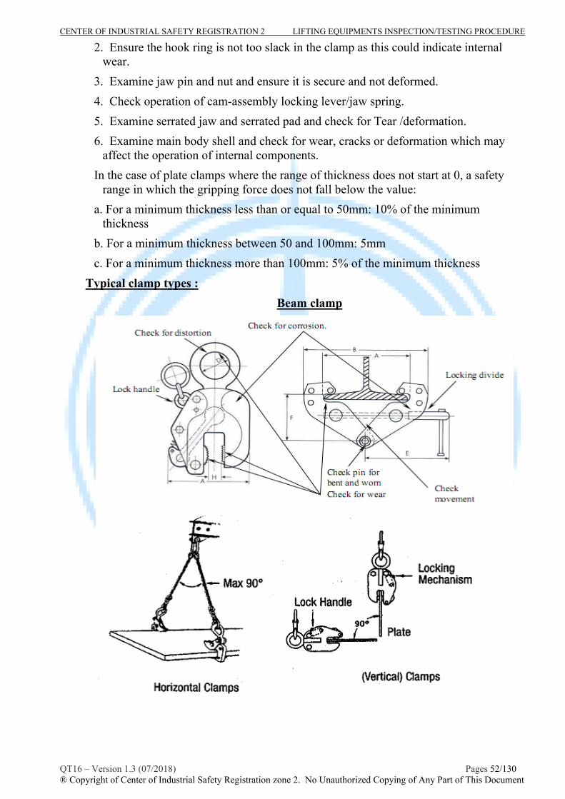
CENTER OF INDUSTRIAL SAFETY REGISTRATION 2 LIFTING EQUIPMENTS INSPECTION/TESTING PROCEDURE
QT16 – Version 1.3 (07/2018) Pages 52/130 ® Copyright of Center of Industrial Safety Registration zone 2. No Unauthorized Copying of Any Part of This Document
2. Ensure the hook ring is not too slack in the clamp as this could indicate internal wear.
3. Examine jaw pin and nut and ensure it is secure and not deformed.
4. Check operation of cam-assembly locking lever/jaw spring.
5. Examine serrated jaw and serrated pad and check for Tear /deformation.
6. Examine main body shell and check for wear, cracks or deformation which may affect the operation of internal components.
In the case of plate clamps where the range of thickness does not start at 0, a safety range in which the gripping force does not fall below the value:
a. For a minimum thickness less than or equal to 50mm: 10% of the minimum thickness
b. For a minimum thickness between 50 and 100mm: 5mm
c. For a minimum thickness more than 100mm: 5% of the minimum thickness
Typical clamp types :
Beam clamp

CENTER OF INDUSTRIAL SAFETY REGISTRATION 2 LIFTING EQUIPMENTS INSPECTION/TESTING PROCEDURE
QT16 – Version 1.3 (07/2018) Pages 53/130 ® Copyright of Center of Industrial Safety Registration zone 2. No Unauthorized Copying of Any Part of This Document
* NDT examination :
Body and weld of clamp should be subjected to magnetic particle or dye penetrant examination in accordance with EN 10228-1 or EN 10228-2(or ASTM E-709 or ASTM E-165) respectively to inspect for surface intersecting discontinuities.
III- Proof load test
Each clamp, after the throughout check, shall be subject to a proof load test. If no specific requirement of manufacturer technical or clien’t requirement, As follow TCVN 4244-2005 standard, appendix 16, the Proof test Load/force (PL) shall be:
* For horizontal and vertical clamp, where SWL 25tons , PL=2x SLW tons ; SWL > 25tons , PL=1,22x SWL+ 20 (tons).
* For beam clamp : PL = 1,5x SWL
The beam/plate clamp shall be carefully loaded in such a way that no significant acceleration forces occur. It shall be held for 5 min before reading taken.
* After load test
After load test, the clamp shall be throughout checked for any damage and defect.
- The test shall be considered satisfactory if no cracks, permanent deformation or damage that would adversely affect the function or safety of clamps is visible.
- If, satisfactory, the clamp shall be stamped the date of inspection on data plate
of the clamp and a report/ certificate shall be issued by the inspector
IV- Schedule of examination and test:
The clamp shall be periodically visual inspected, MT/PT examined with interval not exceeding 12 months (recommendation are 6 months ) such as the schedule inspection of it relevant lifting sling.
Periodic Load test should be caried out in accordance with recommendation of inspector or client requirements.
When the schedule requires a load test, any non-destructive examination and visual inspection shall both be carried out after the load test.
V- Report the result of inspection/testing:
- The inspector shall be completed and reported the result of inspection/testing in accordance with the form M16.7.1 and issued the inspection/loadtest certificate in accordance with the form M16.3.2 . - The inspection certificate shall be issued in accordance with the CISR’s procedure No. TT09.
CENTER OF INDUSTRIAL SAFETY REGISTRATION 2 LIFTING EQUIPMENTS INSPECTION/TESTING PROCEDURE
QT16 – Version 1.3 (07/2018) Pages 54/130 ® Copyright of Center of Industrial Safety Registration zone 2. No Unauthorized Copying of Any Part of This Document
PROCEDURE No : QT 16-DNV.8 INSPECTION, TESTING PROCEDURE FOR
HAMMER LOCKS
A- SCOPE
This part provides general guidelines for competent person performing periodic hammer lock inspection and load testing services to ensure that it is capable of performing the it intended function and fit for use.
The guidance and recommendation will meet the requirements of:
- Manufacturer Recommendation
- TCVN 4244:2005, appendix 11: Vietnamese lifting appliance safety standard.
B- INSPECTION/EXAMINATION/TESTING
I- Technical Requirements prior to inspection:
The inspector, who caried out the inspection/testing, shall be determined clearly the specifications of the hammer lock, e.g WLL, it functions.. by means of review manufactured documents, last inspection/testing report or re-calculated to check.
II - Inspection/Examination Procedure
- Inspector shall carying out visual inspection, records identified information and specifications of hammer lock in to checklist as M16.8.1 form attached in this procedure.
- The hammer lock shall be cleaned prior to each inspection because damage may be hidden by dirt, oil, pain. Adequate lighting should be provided to inspection.
- Hammer locks are designed for using together with chain, master link, hooks and other lifting components as well as with steel wire rope. So hammer locks should have a smooth surface to avoid snagging
- A qualified inspector shall examine deficiencies and determine whether they constitute a safety hazard. Carefully inspected for as requirement below:
* Identification: Check the identification of the hammer lock such as heat number and WLL for model ((Refer to the it technical spec or table 1 & 2 below for dimension and WLL)
* Checked for functional and defects: Check load bearing point, the body of the hammer lock for any wear, nick, gouge, deformation, cracks or other machanical damage and operating functions as follow :
+ Dismantle and Check the pin for wear, distortion or other imperfection.
+ Check loading bearing points for wear, nick, gouge, or cracks.
+ Check for evidence of being welded on the body.

CENTER OF INDUSTRIAL SAFETY REGISTRATION 2 LIFTING EQUIPMENTS INSPECTION/TESTING PROCEDURE
QT16 – Version 1.3 (07/2018) Pages 55/130 ® Copyright of Center of Industrial Safety Registration zone 2. No Unauthorized Copying of Any Part of This Document
Typical hammer lock types :
Coupling link G
Berglock
* NDT examination :
All body and pin of hammer lock should be subjected to magnetic particle or dye penetrant examination in accordance with EN 10228-1 or EN 10228-2(or ASTM E-709 or ASTM E-165) respectively to inspect for surface intersecting discontinuities.
III- Proof load test
The hammer locks shall be load tested together with chain sling, hooks, links and
components in such a way that no significant acceleration forces occur. It shall be held for 5 minutes before reading taken.
The proof load of hammer lock shall be the same with the component that it has been attached to or corresponding with the proof load of the sling leg. . If no specific requirement of manufacturer technical or clien’t requirement, the Proof test Load/force (PL) shall be (TCVN 4244:2005- appendix 11):
+ where SWL 25tons , PL=2x SLW tons ;
+ where SWL > 25tons , PL=1,22x SWL+ 20 (tons).
* After load test
After load test, the hammer lock shall be throughout checked for any damage and defect. The test shall be considered satisfactory if no cracks, permanent

CENTER OF INDUSTRIAL SAFETY REGISTRATION 2 LIFTING EQUIPMENTS INSPECTION/TESTING PROCEDURE
QT16 – Version 1.3 (07/2018) Pages 56/130 ® Copyright of Center of Industrial Safety Registration zone 2. No Unauthorized Copying of Any Part of This Document
deformation or damage that would adversely affect the function or safety of hammer lock is visible. If, satisfactory, the hammer lock shall be stamped the date of inspection on data plate of the hammer lock/the sling that it was attached and a report/ certificate shall be issued by the inspector.
IV- Schedule of examination and test:
The hammer lock shall be periodically visual inspected, MT/PT examined with interval not exceeding 12 months (recommendation are 6 months ) such as the schedule inspection of it relevant lifting sling.
Periodic Load test should be caried out in accordance with recommendation of inspector or client requirements.
When the schedule requires a load test, any non-destructive examination and visual inspection shall both be carried out after the load test.
V- Report the result of inspection/testing:
- The inspector shall be completed and reported the result of inspection/testing in accordance with the form M16.8.1 nd issued the inspection/loadtest certificate in accordance with the form M16.3.2 - The inspection certificate shall be issued in accordance with CISR’s procedure No. TT09.

CENTER OF INDUSTRIAL SAFETY REGISTRATION 2 LIFTING EQUIPMENTS INSPECTION/TESTING PROCEDURE
QT16 – Version 1.3 (07/2018) Pages 57/130 ® Copyright of Center of Industrial Safety Registration zone 2. No Unauthorized Copying of Any Part of This Document
PROCEDURE No : QT 16-DNV.9 INSPECTION, TESTING PROCEDURE FOR
SWIVEL HOIST RINGS/ SWIVEL EYEBOLTS
A- SCOPE
This part provides general guidelines for competent person performing periodic swivel hoist rings/swivel eyebolt inspection and load testing services to ensure that it is capable of performing the it intended function and fit for use.
The guidance and recommendation will meet the requirements of:
- Manufacturer Recommendation
- BS 4278 : Eyebolt for lifting purpose
- TCVN 4244:2005, appendix 11: Vietnamese lifting appliance safety standard.
- DOE-STD-1090 Hoisting and Rigging
B- INSPECTION/EXAMINATION/TESTING
I- Technical Requirements prior to inspection:
The inspector, who caried out the inspection/testing, shall be determined clearly the specifications of the swivel hoist rings/swivel eyebolt, e.g WLL by means of review manufactured documents, last inspection/testing report or re-calculated to check.
II - Inspection/Examination Procedure
- Inspector shall carying out visual inspection, records identified information and specifications of hammer lock in to checklist as M16.9.1 form attached in this procedure.
- The swivel hoist rings/swivel eyebolt shall be cleaned prior to each inspection because damage may be hidden by dirt, oil, pain. Adequate lighting should be provided to inspection.
- A qualified inspector shall examine deficiencies and determine whether they constitute a safety hazard. Carefully inspected for as requirement below:
* Identification: Check the identification of the swivel hoist rings/swivel eyebolt and it WLL that has been forged, stamped or inscribed into each swivel hoist ring, permanently attached metal tag bearing the same information may also use (Consider the angle of the load to the axis of the screw thread of eye bolt. Refer to table below for the rated capacity of the swivel hoisting ring).
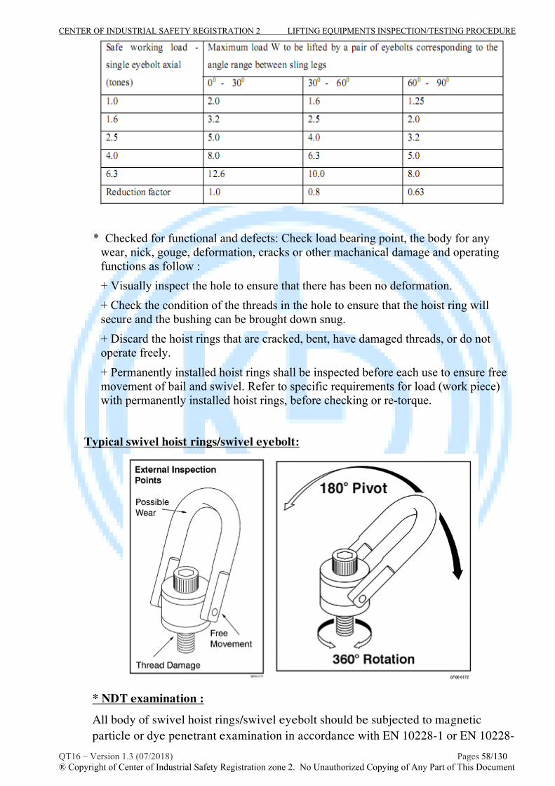
CENTER OF INDUSTRIAL SAFETY REGISTRATION 2 LIFTING EQUIPMENTS INSPECTION/TESTING PROCEDURE
QT16 – Version 1.3 (07/2018) Pages 58/130 ® Copyright of Center of Industrial Safety Registration zone 2. No Unauthorized Copying of Any Part of This Document
* Checked for functional and defects: Check load bearing point, the body for any wear, nick, gouge, deformation, cracks or other machanical damage and operating functions as follow :
+ Visually inspect the hole to ensure that there has been no deformation.
+ Check the condition of the threads in the hole to ensure that the hoist ring will secure and the bushing can be brought down snug.
+ Discard the hoist rings that are cracked, bent, have damaged threads, or do not operate freely.
+ Permanently installed hoist rings shall be inspected before each use to ensure free movement of bail and swivel. Refer to specific requirements for load (work piece) with permanently installed hoist rings, before checking or re-torque.
Typical swivel hoist rings/swivel eyebolt:
* NDT examination :
All body of swivel hoist rings/swivel eyebolt should be subjected to magnetic particle or dye penetrant examination in accordance with EN 10228-1 or EN 10228-

CENTER OF INDUSTRIAL SAFETY REGISTRATION 2 LIFTING EQUIPMENTS INSPECTION/TESTING PROCEDURE
QT16 – Version 1.3 (07/2018) Pages 59/130 ® Copyright of Center of Industrial Safety Registration zone 2. No Unauthorized Copying of Any Part of This Document
2(or ASTM E-709 or ASTM E-165) respectively to inspect for surface intersecting discontinuities in accordance with inspector or client requirement.
III- Proof load test
The Swivel hoist rings shall be load tested in such a way that no significant acceleration forces occur. It shall be held for 5 minutes before reading taken.
If no specific requirement of manufacturer technical or clien’t requirement, the Proof test Load/force (PL) shall be (TCVN 4244:2005- appendix 14):
+ where WLL 25tons , PL=2x WLL tons ;
+ where WLL > 25tons , PL=1,22x WLL+ 20 (tons).
Test weights shall be accurate to with -5 percent, +0 percent of stipulated values.
If proof testing cannot be verified, the swivel hoist rings shall be proof tested before being used to make a critical lift.
After load test, the Swivel hoist rings shall be throughout checked for any damage and defect. The test shall be considered satisfactory if no cracks, permanent deformation or damage that would adversely affect the function or safety of Swivel hoist rings is visible. If, satisfactory, the Swivel hoist rings shall be stamped the date of inspection on data plate and a report/ certificate shall be issued by the inspector.
IV- Schedule of examination and test:
The Swivel hoist rings shall be periodically visual inspected, MT/PT examined with interval not exceeding 12 months (recommendation are 6 months ).
Periodic Load test should be caried out in accordance with recommendation of inspector or client requirements.
When the schedule requires a load test, any non-destructive examination and visual inspection shall both be carried out after the load test.
V- Report the result of inspection/testing:
- The inspector shall be completed and reported the result of inspection/testing in accordance with the form M16.9.1 nd issued the inspection/loadtest certificate in accordance with the form M16.3.2 - The inspection certificate shall be issued in accordance with the CISR’s procedure No. TT09.

CENTER OF INDUSTRIAL SAFETY REGISTRATION 2 LIFTING EQUIPMENTS INSPECTION/TESTING PROCEDURE
QT16 – Version 1.3 (07/2018) Pages 60/130 ® Copyright of Center of Industrial Safety Registration zone 2. No Unauthorized Copying of Any Part of This Document
PROCEDURE No : QT 16-DNV.10 INSPECTION, TESTING PROCEDURE FOR
EYEBOLTS/ EYENUTS
A- SCOPE
This part provides general guidelines for competent person performing periodic eyebolt inspection and load testing services to ensure that it is capable of performing the it intended function and fit for use.
The guidance and recommendation will meet the requirements of:
- BS 4278:1984 : Eyebolt for lifting purpose
- TCVN 4244:2005, appendix 11: Vietnamese lifting appliance safety standard.
- DOE-STD-1090 Hoisting and Rigging
B- INSPECTION/EXAMINATION/TESTING
I- Technical Requirements prior to inspection:
The inspector, who caried out the inspection/testing, shall be determined clearly the specifications of the eyebolt, e.g WLL by means of review manufactured documents, last inspection/testing report or re-calculated to check.
II - Inspection/Examination Procedure
- Inspector shall carying out visual inspection, records identified information and specifications of eyebolts in to checklist as M16.10.1 form attached in this procedure (refer to it technical document or the table below for specifications).
- The eyebolt shall be cleaned prior to each inspection because damage may be hidden by dirt, oil, pain. Adequate lighting should be provided to inspection.
- A qualified inspector shall examine deficiencies and determine whether they constitute a safety hazard. Carefully inspected for as requirement below:
* The Eyebolt shall be marked with :
+ Carbon Steel Eyebolts shall have the manufacturer’s name or identification trademark forged inraised characters on the surface of the eyebolt.
+ Alloy Steel Eyebolts shall have the symbol “A” (denoting alloy steel) and the manufacturer’s name or identification mark forged in raised characters on the surface of the eyebolt.
* Checked for functional and defects: Check load bearing point, the body for any wear, nick, gouge, deformation, cracks or other machanical damage and operating functions as follow :
+ Visual check for shape of eye bolt and any distortion i.e. bent shank, deformed eye, etc. Ensure that the shank of the eyebolt is not undercut and is smoothly radiused into the plane of the shoulder or the contour of the ring for nonshouldered eyebolts.
+ Inspect for any damage or corrosion on the thread or if incorrectly formed.

CENTER OF INDUSTRIAL SAFETY REGISTRATION 2 LIFTING EQUIPMENTS INSPECTION/TESTING PROCEDURE
QT16 – Version 1.3 (07/2018) Pages 61/130 ® Copyright of Center of Industrial Safety Registration zone 2. No Unauthorized Copying of Any Part of This Document
+ Check for general damage i.e. nicks, gouges, or corrosion
Safety loading of eyebolt:

CENTER OF INDUSTRIAL SAFETY REGISTRATION 2 LIFTING EQUIPMENTS INSPECTION/TESTING PROCEDURE
QT16 – Version 1.3 (07/2018) Pages 62/130 ® Copyright of Center of Industrial Safety Registration zone 2. No Unauthorized Copying of Any Part of This Document
* NDT examination :
All body of eyebolt should be subjected to magnetic particle or dye penetrant examination in accordance with EN 10228-1 or EN 10228-2(or ASTM E-709 or ASTM E-165) respectively to inspect for surface intersecting discontinuities in accordance with inspector or client requirement.
III- Proof load test
The eye bolt shall be load tested in such a way that no significant acceleration forces occur. It shall be held for 5 minutes before reading taken.
If no specific requirement of manufacturer technical or clien’t requirement, the Proof test Load/force (PL) shall be (TCVN 4244:2005- appendix 14):
+ where WLL 25tons , PL=2x WLL tons ;
+ where WLL > 25tons , PL=1,22x WLL+ 20 (tons).
Test weights shall be accurate to with -5 percent, +0 percent of stipulated values.
If proof testing cannot be verified, the eye bolt shall be proof tested before being used to make a critical lift.
After load test, the eye bolt shall be throughout checked for any damage and defect. The test shall be considered satisfactory if no cracks, permanent deformation or damage that would adversely affect the function or safety of eye bolt is visible. If, satisfactory, the eye bolt shall be stamped the date of inspection on data plate and a report/ certificate shall be issued by the inspector.
IV- Schedule of examination and test:
The eye bolt shall be periodically visual inspected, MT/PT examined with interval not exceeding 12 months (recommendation are 6 months ).
Periodic Load test should be caried out in accordance with recommendation of inspector or client requirements.
When the schedule requires a load test, any non-destructive examination and visual inspection shall both be carried out after the load test.
V- Report the result of inspection/testing:
- The inspector shall be completed and reported the result of inspection/testing in accordance with the form M16.10.1 and issued the inspection/loadtest certificate in accordance with the form M16.3.2. - The inspection certificate shall be issued in accordance with the CISR’s procedure No. TT09.
CENTER OF INDUSTRIAL SAFETY REGISTRATION 2 LIFTING EQUIPMENTS INSPECTION/TESTING PROCEDURE
QT16 – Version 1.3 (07/2018) Pages 63/130 ® Copyright of Center of Industrial Safety Registration zone 2. No Unauthorized Copying of Any Part of This Document
PROCEDURE No : QT 16-DNV.11 INSPECTION, TESTING PROCEDURE FOR
TURNBUCKLES
A- SCOPE
This part provides general guidelines for competent person performing periodic turn buckle inspection and load testing services to ensure that it is capable of performing the it intended function and fit for use.
The guidance and recommendation will meet the requirements of:
- TCVN 4244:2005, appendix 15: Vietnamese lifting appliance safety standard.
- DOE-STD-1090 CHAPTER 12 Rigging Accessories.
- NSL : Lifting equipment legislation matrix.
B- INSPECTION/EXAMINATION/TESTING
I- Technical Requirements prior to inspection:
The inspector, who caried out the inspection/testing, shall be determined clearly the specifications of the turn buckle, e.g rated capacity by means of review manufactured documents, last inspection/testing report.
II - Inspection/Examination Procedure
- Inspector shall carying out visual inspection, records identified information of specifications of turn buckle in to checklist as M16.11.1 form attached in this procedure (refer to it technical document or the table below for specifications).
- The turn buckle shall be cleaned prior to each inspection because damage may be hidden by dirt, oil, pain. Adequate lighting should be provided to inspection.
- Turnbuckles may be used in sling systems provided that they are engineered, designed, and approved as a part of the sling system. Approved turnbuckles shall be marked and identified for use with the sling set for which they were designed and shall be load-tested as part of the sling set.
- Before each use or periodically, turnbuckles shall be inspected for damage. damaged threads, jamb nuts, or bent frame members make the unit unsuitable for use.
- Jamb nuts or locking devices must be tightened or locked before making lifts with turnbuckles. See Figure below for turnbuckle concentrated inspection areas.
* Checked for functional and defects: Check load bearing point, the body for any wear, nick, gouge, deformation, cracks or other machanical damage and operating functions as follow :
+ Visual check for shape of turnbuckle and any distortion i.e. bent, deformed eye or hook, etc.
+ Inspect for any damage or corrosion on the thread or if incorrectly formed.

CENTER OF INDUSTRIAL SAFETY REGISTRATION 2 LIFTING EQUIPMENTS INSPECTION/TESTING PROCEDURE
QT16 – Version 1.3 (07/2018) Pages 64/130 ® Copyright of Center of Industrial Safety Registration zone 2. No Unauthorized Copying of Any Part of This Document
+ Check for general damage i.e. nicks, gouges, or corrosion.
Typical turnbuckle :
* NDT examination :
All eyes, hooks, jaws should be subjected to magnetic particle or dye penetrant examination in accordance with EN 10228-1 or EN 10228-2(or ASTM E-709 or ASTM E-165) respectively to inspect for surface intersecting discontinuities in accordance with inspector or client requirement.
III- Proof load test
The turnbuckle shall be load tested in such a way that no significant acceleration forces occur. It shall be held for 5 minutes before reading taken.
If no specific requirement of manufacturer technical or clien’t requirement, the Proof test Load/force (PL) shall be (TCVN 4244:2005- appendix 15)PL=2x WLL

CENTER OF INDUSTRIAL SAFETY REGISTRATION 2 LIFTING EQUIPMENTS INSPECTION/TESTING PROCEDURE
QT16 – Version 1.3 (07/2018) Pages 65/130 ® Copyright of Center of Industrial Safety Registration zone 2. No Unauthorized Copying of Any Part of This Document
Test weights/test force shall be accurate to with -5 percent, +0 percent of stipulated values.
After load test, the turnbuckle shall be throughout checked for any damage and defect. The test shall be considered satisfactory if no cracks, permanent deformation or damage that would adversely affect the function or safety of turnbuckle is visible. If, satisfactory, the eye bolt shall be stamped the date of inspection on data plate and a report/ certificate shall be issued by the inspector.
IV- Schedule of examination and test:
The turnbuckle shall be periodically visual inspected, MT/PT examined with interval not exceeding 12 months (recommendation are 6 months ).
Periodic Load test should be caried out in accordance with recommendation of inspector or client requirements.
When the schedule requires a load test, any non-destructive examination and visual inspection shall both be carried out after the load test.
V- Report the result of inspection/testing:
- The inspector shall be completed and reported the result of inspection/testing in accordance with the form M16.11.1 and issued the inspection/loadtest certificate in accordance with the form M16.3.2 . - The inspection certificate shall be issued in accordance with the CISR’s procedure No. TT09.

CENTER OF INDUSTRIAL SAFETY REGISTRATION 2 LIFTING EQUIPMENTS INSPECTION/TESTING PROCEDURE
QT16 – Version 1.3 (07/2018) Pages 66/130 ® Copyright of Center of Industrial Safety Registration zone 2. No Unauthorized Copying of Any Part of This Document
PROCEDURE No : QT 16-DNV.12 INSPECTION, TESTING PROCEDURE FOR
SHEAVE BLOCKS
A- SCOPE
This part provides general guidelines for competent person performing periodic personal sheave blocks inspection and load testing services to ensure that it is capable of performing the it intended function and fit for use.
The guidance and recommendation will meet the requirements of:
- DNV Standard for certification of lifting appliance No.2.2.2
- TCVN 4244:2005, appendix 15: Vietnamese lifting appliance safety standard.
B- INSPECTION/EXAMINATION/TESTING
I- Technical Requirements prior to inspection:
The inspector, who caried out the inspection/testing, shall be determined clearly the specifications of the sheave blocks, e.g rated capacity by means of review manufactured documents, last inspection/testing report.
II - Inspection/Examination Procedure
- Inspector shall carying out visual inspection, records identified information of specifications of sheave blocks in to checklist as M16.12.1 form attached in this procedure (refer to it technical document or the table below for specifications).
- The sheave blocks shall be cleaned prior to each inspection because damage may be hidden by dirt, oil, pain. Adequate lighting should be provided to inspection.
* Checked for functional and defects: Check load bearing point, the body for any wear, nick, gouge, deformation, cracks or other machanical damage and operating functions as follow :
The qualified inspector should check if the sheave rotates freely by hand
The depth of the groove in the sheave should preferably be equal to the diameter of the rope, but in no case should it be less than three-quarters of the diameter of the rope.
The surface of the groove and the outside rim of the sheave should be clean, smooth and free from sharp edges, projections or other defects liable to injure the rope. The edges of the groove should be radiused.
The contour at the bottom of the groove should be circular over an angle of 1280
(corresponding to an angle of flare of 520)
- For Swivel head fittings: Examine the nut or collar of the shank, to ensure that it is securely fastened and free from visible defects. See that the shank is not distorted and turns freely by hand, and that the clearance is not excessive. Grease or oil the shank and the bearing surface of the nut or collar.
- For Binding: Examine for fractures and wastage due to corrosion.

CENTER OF INDUSTRIAL SAFETY REGISTRATION 2 LIFTING EQUIPMENTS INSPECTION/TESTING PROCEDURE
QT16 – Version 1.3 (07/2018) Pages 67/130 ® Copyright of Center of Industrial Safety Registration zone 2. No Unauthorized Copying of Any Part of This Document
- For Side or partition plates: Examine to see these are not buckled or distorted. Buckled side or partition plates may allow the rope to jam between the sheave or side and partition plate: this has been the cause of many accidents.
- Sheaves: Examine for cracks. Verify that the bush is not slack in the sheave and is not worn where in contact with the axle pin. See that each sheave turns freely by hand.
Examine the fit of the rope in the grooves of the sheaves. This is particularly important when a new rope is first reeved, since a worn sheave may result in a high rate of rope wear.
- Axle pins: Examine axle pins for wear; check that they do not rotate, also that they are securely held in place to prevent the pins working out of the shell of the block .
Typical sheave blocks :

CENTER OF INDUSTRIAL SAFETY REGISTRATION 2 LIFTING EQUIPMENTS INSPECTION/TESTING PROCEDURE
QT16 – Version 1.3 (07/2018) Pages 68/130 ® Copyright of Center of Industrial Safety Registration zone 2. No Unauthorized Copying of Any Part of This Document
* NDT examination :
All body, sheave and axle pin should be subjected to magnetic particle or dye penetrant examination in accordance with EN 10228-1 or EN 10228-2(or ASTM E-709 or ASTM E-165) respectively to inspect for surface intersecting discontinuities in accordance with inspector or client requirement.
III- Proof load test
The sheave blocks shall be load tested in such a way that no significant acceleration forces occur. It shall be held for 5 minutes before reading taken. Test weights/test force shall be accurate to with -5 percent, +0 percent of stipulated values.
If no specific requirement of manufacturer technical or clien’t requirement, the Proof test Load/force (PL) shall be as requirement of DNV standard No.2.2.2 as follow:
- Single Sheave Block : PL = 4 SWL
- Multi sheaves Block :
SWL 25tonnes : PL = 2x SWL
25tonnes < SWL 160 tonnes : PL = 0,993 SWL +27tonnes
SWL > 160 tonnes : PL = 1,1 x SWL
In the case of multiple sheave blocks, the safe working load is the resultant load on the head fitting.
In the case of single sheave blocks, the resultant load on the head fitting will be twice the safe working load (SWL) marked on the block.
There should be a separate test on the becket, and its safe working load should be taken as one-fifth of the minimum breaking load of the wire rope.

CENTER OF INDUSTRIAL SAFETY REGISTRATION 2 LIFTING EQUIPMENTS INSPECTION/TESTING PROCEDURE
QT16 – Version 1.3 (07/2018) Pages 69/130 ® Copyright of Center of Industrial Safety Registration zone 2. No Unauthorized Copying of Any Part of This Document
The testing machine should be verified in accordance with the requirements of BS 1610, and maintained within grade B. Its full load should be not more than 10 times the proof load.
- Examination after load test:
After proof loading, all parts of the blocks should be thoroughly examined by a competent person. The shanks of the swivel head fittings and the sheaves should rotate freely by hand, and the block should be accepted only if found free from deformation, cracks, flaws, or other defects.
If satisfactory, the sheave blocks shall be color coded, hard stamped with test details and a report or certificate will be issued.
IV- Schedule of examination and test:
The sheave blocks shall be periodically visual inspected, MT/PT examined with interval not exceeding 12 months (recommendation are 6 months ).
Periodic Load test should be caried out in accordance with recommendation of inspector or client requirements.
When the schedule requires a load test, any non-destructive examination and visual inspection shall both be carried out after the load test.
V- Report the result of inspection/testing:
- The inspector shall be completed and reported the result of inspection/testing in accordance with the form M16.12.1 and issued the inspection/loadtest certificate in accordance with the form M6.3.2 . - The inspection certificate shall be issued in accordance with the CISR’s procedure No. TT09.

CENTER OF INDUSTRIAL SAFETY REGISTRATION 2 LIFTING EQUIPMENTS INSPECTION/TESTING PROCEDURE
QT16 – Version 1.3 (07/2018) Pages 70/130 ® Copyright of Center of Industrial Safety Registration zone 2. No Unauthorized Copying of Any Part of This Document
PROCEDURE No : QT 16-DNV.13 INSPECTION, TESTING PROCEDURE FOR
PERSONAL LIFTING PLATFORM/SUSPENDED BASKETS
A- SCOPE
This part provides general guidelines for competent person performing periodic personal platform inspection and load testing services to ensure that it is capable of performing the it intended function and fit for use.
The guidance and recommendation will meet the requirements of:
- BSEN 14502-1-2005 (Suspended basket)
- DOE-STD-1090 Chapter 4 (Personal Lifting)
B- INSPECTION/EXAMINATION/TESTING
I- Technical Requirements prior to inspection:
The inspector, who caried out the inspection/testing, shall be determined clearly the specifications of the personal platform, e.g rated capacity by means of review manufactured documents, last inspection/testing report.
II - Inspection/Examination Procedure
- Inspector shall carying out visual inspection, records identified information of specifications of personal platform in to checklist as M16.1.1 form attached in this procedure.
- Adequate lighting and other facilities should be provided to caried out the inspection in all side of platform.
- Marking : Suspended baskets shall be fitted with a plate durably marked, with the following information and in visible position:
a) name and address of the manufacturer or supplier;
b) year of construction;
c) type;
d) identification number;
e) dead weight of the suspended basket;
f) rated capacity of the suspended basket and maximum number of persons permitted in it.
- Suspended baskets used on cranes shall be painted in a conspicuous colour. * Checked for dimensional, functional and defects:
+ All platform suspension system such as: wire rope, shackles, rings, master links, and other rigging hardware shall be inspected/examined for any damage, crack, or excessive wear in accordance with the it relevant inspection procedures/standards mentioned in this document.

CENTER OF INDUSTRIAL SAFETY REGISTRATION 2 LIFTING EQUIPMENTS INSPECTION/TESTING PROCEDURE
QT16 – Version 1.3 (07/2018) Pages 71/130 ® Copyright of Center of Industrial Safety Registration zone 2. No Unauthorized Copying of Any Part of This Document
Note: Shackles used in any part of the suspension system shall be a safety type (bolt type shackle with nut and cotter pin).
The rope end terminations shall be fabricated with thimbles spliced eyes with thimble according to EN 13411-2 or ferrule secured eyes with thimble according to EN 13411-3 or thimbles shall be constructed according to EN 13411-1.
Wire rope clips, wedge sockets, or knots shall not be used for the suspension system.
Synthetic webbing, natural or synthetic fiber rope shall not be used for the suspension system.
Chain sling suspension system shall use a minimum of grade 80 chain with safety factor of at least 8 x (weight of basket + rated capacity) and 10 x (weight of basket + rated capacity) for steel wire ropes including the end termination.
+ The floor of platform shall be secured to the frame by welding or some other equally
effective means (e.g. bolted) , slip resistant and have drainage. Any aperture in the floor of the platform shall have dimension through which a sphere of 20mm cannot pass through.
+ When hanging from the hook, the vertical distance between the floor of the platform and the crane hook shall be ≥ 3m.
+ When the suspended basket is designed to be used in situations where falling objects may be a hazard, the basket shall be provided with a roof. Any aperture in the roof of the basket shall have dimensions which shall not allow a sphere of 20 mm to pass through. As a minimum the roof of the basket shall be able to withstand the impact of a steel ball weighing 7 kg, falling from a height of 2 m, without plastic deformations exceeding 50 mm.
+ Suspended baskets shall be protected against corrosion.
+ When calculating the rated capacity of the suspended basket the weight of each person shall be taken as at least 80 kg plus at least 40 kg of equipment for each person
+ Load lifting attachment(s) shall be fitted to the basket in such a way that they can only be removed with tools.
+ The free space on the floor shall be at least 0,6 m x 0,6 m for one person, and at least 0,4 m x 0,4 m more for each additional person.
+ Suspended baskets shall have on each side:
• a side protection with the following characteristics:
� enclosed up to a height of at least 0,5 m so that a sphere of 20 mm cannot pass through;
� the top of the enclosure shall be fitted with a guard rail;
� if the guard rail is lower than 1 m above the floor, another guard rail shall be provided at 1 m;
• a hand rail of at least 16 mm and not more than 40 mm diameter. To avoid crushing hands it shall be located 0,075 m to 0,1 m inside and 0,075 m to 0,1 m above the upper edge of the side protection (see Figure below).
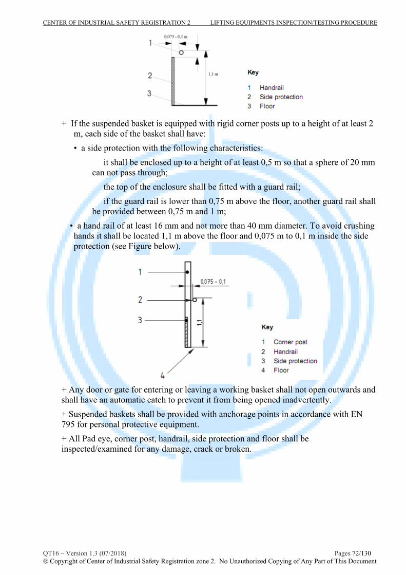
CENTER OF INDUSTRIAL SAFETY REGISTRATION 2 LIFTING EQUIPMENTS INSPECTION/TESTING PROCEDURE
QT16 – Version 1.3 (07/2018) Pages 72/130 ® Copyright of Center of Industrial Safety Registration zone 2. No Unauthorized Copying of Any Part of This Document
+ If the suspended basket is equipped with rigid corner posts up to a height of at least 2
m, each side of the basket shall have:
• a side protection with the following characteristics:
� it shall be enclosed up to a height of at least 0,5 m so that a sphere of 20 mm can not pass through;
� the top of the enclosure shall be fitted with a guard rail;
� if the guard rail is lower than 0,75 m above the floor, another guard rail shall be provided between 0,75 m and 1 m;
• a hand rail of at least 16 mm and not more than 40 mm diameter. To avoid crushing hands it shall be located 1,1 m above the floor and 0,075 m to 0,1 m inside the side protection (see Figure below).
+ Any door or gate for entering or leaving a working basket shall not open outwards and shall have an automatic catch to prevent it from being opened inadvertently.
+ Suspended baskets shall be provided with anchorage points in accordance with EN 795 for personal protective equipment.
+ All Pad eye, corner post, handrail, side protection and floor shall be inspected/examined for any damage, crack or broken.

CENTER OF INDUSTRIAL SAFETY REGISTRATION 2 LIFTING EQUIPMENTS INSPECTION/TESTING PROCEDURE
QT16 – Version 1.3 (07/2018) Pages 73/130 ® Copyright of Center of Industrial Safety Registration zone 2. No Unauthorized Copying of Any Part of This Document
Typical personal platform :
Suspended basket longer than 2 m Suspended basket with single suspension
Suspended basket longer than 2 m Personnel Lift Platform
* NDT examination :
All padye, suspended point.. should be subjected to magnetic particle or dye penetrant examination in accordance with EN 10228-1 or EN 10228-2(or ASTM E-709 or ASTM E-165) respectively to inspect for surface intersecting discontinuities in accordance with inspector or client requirement.
III- Proof load test
The personal platform with lifting accessories shall be load tested in such a way that no significant acceleration forces occur. It shall be held for 5 minutes before reading taken. Test weights/test force shall be accurate to with -5 percent, +0 percent of stipulated values with the load suitably distributed.

CENTER OF INDUSTRIAL SAFETY REGISTRATION 2 LIFTING EQUIPMENTS INSPECTION/TESTING PROCEDURE
QT16 – Version 1.3 (07/2018) Pages 74/130 ® Copyright of Center of Industrial Safety Registration zone 2. No Unauthorized Copying of Any Part of This Document
If no specific requirement of manufacturer technical or clien’t requirement, the Proof test Load/force (PL) shall be as follow table for detail:
+ At least annually and at each new job site, before personnel are hoisted, the personnel platform and suspension system shall be load-tested to 150 percent of the personnel platform’s rated capacity, the load is applied at the worst position on the floor, any resulting inclination shall not exceed 20o.
+ Structural repair or modification to the platform requires load-testing to 150 percent of the rated capacity.
d. After load-testing, any deficiencies revealed during the inspection shall be corrected and another load test shall be conducted.
- Examination after load test :
After proof loading, all parts of the platform with lifting accessories should be thoroughly examined by a competent person. It should be accepted only if found free from deformation, cracks, flaws, or other defects.
If satisfactory, the personal platform shall be color coded, hard stamped with test details and a report or certificate will be issued.
IV- Schedule of examination and test:
The personal platform shall be periodically visual inspected, MT/PT examined with interval not exceeding 12 months (recommendation are 6 months ).
Periodic Load test should be caried out in accordance with recommendation of inspector or client requirements at least annually.
When the schedule requires a load test, any non-destructive examination and visual inspection shall both be carried out after the load test.
V- Report the result of inspection/testing:
- The inspector shall be completed and reported the result of inspection/testing in accordance with the form M16.1.1 and issued the inspection/loadtest certificate in accordance with the form M16.1.2 . - The inspection certificate shall be issued in accordance with the CISR’s procedure No. TT09.

CENTER OF INDUSTRIAL SAFETY REGISTRATION 2 LIFTING EQUIPMENTS INSPECTION/TESTING PROCEDURE
QT16 – Version 1.3 (07/2018) Pages 75/130 ® Copyright of Center of Industrial Safety Registration zone 2. No Unauthorized Copying of Any Part of This Document
PROCEDURE No : QT 16-DNV.14 INSPECTION, TESTING PROCEDURE FOR
LIFTING BEAM, LIFTING SPREADER, LIFTING FRAME
A- SCOPE
This part provides general guidelines for competent person performing periodic lifting beam/spreader/frame inspection and load testing services to ensure that it is capable of performing the it intended function and fit for use.
The guidance and recommendation will meet the requirements of:
- DNV Standard for certification of lifting appliance No.2.2.2
- BSEN 13001, Crane safety - General design. General principles and requirements.
- BSEN 13155: Crane safety- none fixed load lifting attachments
- The International Rigging & Lifting Handbook (NSL Communicating Safety )
- ASME B30.20 : Below the hook lifting devices
- TCVN 4244:2005: Vietnamese lifting appliance safety standard.
B- INSPECTION/EXAMINATION/TESTING
I- Technical Requirements prior to inspection:
The inspector, who caried out the inspection/testing, shall be determined clearly the specifications of the lifting beam/spreader, e.g rated capacity by means of review manufactured documents, last inspection/testing report.
II - Inspection/Examination Procedure
- Inspector shall carying out visual inspection, records identified information of specifications of lifting beam in to checklist as M16.1.1 form attached in this procedure .
- Adequate lighting and other facilities should be provided to caried out the inspection in all side of lifting beam/spreader.
- Marking : The rated capacity of each lifting device shall be marked on the main structure where it is visible and legible. If the lifting device comprises several items, each detachable from the assembly, each lifting device shall be marked with its rated capacity. At aminimum, a nameplate, name tag, or other permanent marker shall be affixed displaying the following data.
+ Manufacturer’s name
+ Lifting device weight (if over 100 lb).
+ Serial number (if applicable).
+ Rated capacity.
CENTER OF INDUSTRIAL SAFETY REGISTRATION 2 LIFTING EQUIPMENTS INSPECTION/TESTING PROCEDURE
QT16 – Version 1.3 (07/2018) Pages 76/130 ® Copyright of Center of Industrial Safety Registration zone 2. No Unauthorized Copying of Any Part of This Document
- Loose equipments which was attached with beam/spreader shall be inspected according to their relevant procedures/standard metioned in this document.
- Checked for dimensional, functional and defects:
+Structural deformation, cracks, or excessive wear on any part : The beam/spreader shall be replaced if
Plate : Any loss of metal exceed to 10% of plate thickness, 20% of plate thickness in the localized area.
Section of structure : Any loss of metal exceed to 10% of section area, 20% of section area in the localized area of auxiliary structure, reduce 3% in diameter with the circle sections.
Note : The inspector shall be measured the mentioned thickness by adequate method, e.g. UT..
+ Loose or missing guards, fasteners, covers, stops, or nameplates.
+ All operating mechanisms and automatic hold-and-release mechanisms
for misadjustments interfering with operation.
+ Loose bolts or fasteners.
+ Check for suspect/counterfeit parts (see Terminology and Definitions).
+ Cracked or worn gears, pulleys, sheaves, sprockets, bearings, chains, and belts.
+ Excessive wear of friction pads, linkages, and other mechanical parts.
+ Excessive wear at hoist-attaching points and load-support shackles or pins.
+ External evidence of damage to motors or controls.
+ Particular attention shall be paid to hollow sections which may have dents or localized buckling and to the flanges of structural steel sections.
+ Check for signs of cracking or distortion around welds.
Note: If the lifting beam is intended to tilt, the manufacturer shall indicate the maximum permissible angle of tilt from the horizontal. If the lifting beam is intended for horizontal use, the design shall tolerate a tilt of up to 60 from the horizontal.
If any of the above are found defective the lifting beam/spreader shall be taken out of service repairing.

CENTER OF INDUSTRIAL SAFETY REGISTRATION 2 LIFTING EQUIPMENTS INSPECTION/TESTING PROCEDURE
QT16 – Version 1.3 (07/2018) Pages 77/130 ® Copyright of Center of Industrial Safety Registration zone 2. No Unauthorized Copying of Any Part of This Document
Typical lifting beam/ spreader bar/frame :
Load-supporting lifting devices
Friction-type pressure gripping lifting devices.
Indentation-type gripping lifting device
Typical cask lift fixture

CENTER OF INDUSTRIAL SAFETY REGISTRATION 2 LIFTING EQUIPMENTS INSPECTION/TESTING PROCEDURE
QT16 – Version 1.3 (07/2018) Pages 78/130 ® Copyright of Center of Industrial Safety Registration zone 2. No Unauthorized Copying of Any Part of This Document
* NDT examination :
All padye, suspended point, hooks, lifting forced welds.. should be subjected to magnetic particle or dye penetrant examination in accordance with EN 10228-1 or EN 10228-2(or ASTM E-709 or ASTM E-165) respectively to inspect for surface intersecting discontinuities in accordance with inspector or client requirement.
III- Proof load test
The lifting beam/spreader shall be load tested in such a way that no significant acceleration forces occur. It shall be held for 10 minutes before reading taken. Test weights/test force shall be accurate to with -5 percent, +0 percent of stipulated values with the load suitably distributed.
If no specific requirement of manufacturer technical or clien’t requirement, the Proof test Load/force (PL) shall be (DNV No.2.2.2):
+ where SWL 10tonnes , PL=2x SWLtonnes ;
+ where 10tonnes < SWL 160tonnes , PL=1,04x SWL+ 9,6 tonnes.
+ where SWL > 160tonnes , PL=1,1x SWL.
- Examination after load test :
After proof loading, all parts of the beam/spreader should be thoroughly examined by a competent person. It should be accepted only if found free from deformation, cracks, flaws, or other defects.
If satisfactory, the beam/spreader shall be marked with test details and a report or certificate will be issued.
IV- Schedule of examination and test:
The beam/spreader shall be periodically visual inspected, MT/PT examined with interval not exceeding 12 months (recommendation are 6 months ).
Periodic Load test should be caried out in accordance with recommendation of inspector or client requirements at least annually.
When the schedule requires a load test, any non-destructive examination and visual inspection shall both be carried out after the load test.
V- Report the result of inspection/testing:
- The inspector shall be completed and reported the result of inspection/testing in accordance with the form M16.1.1 and issued the inspection/loadtest certificate in accordance with the form M16.1.2 - The inspection certificate shall be issued in accordance with the CISR’s procedure No. TT09.

CENTER OF INDUSTRIAL SAFETY REGISTRATION 2 LIFTING EQUIPMENTS INSPECTION/TESTING PROCEDURE
QT16 – Version 1.3 (07/2018) Pages 79/130 ® Copyright of Center of Industrial Safety Registration zone 2. No Unauthorized Copying of Any Part of This Document
PROCEDURE No : QT 16-DNV.15 INSPECTION, TESTING PROCEDURE FOR
MANUAL OPERATED CHAIN HOIST
A- SCOPE
This procedure provides general guidelines for competent person performing periodic manual operated chain hoist (chain block and lever chai hoist, with friction brake type load-controlling mechanisms) inspection and load testing services to ensure that it is capable of performing the it intended function and fit for use.
The guidance and recommendation will meet the requirements of:
- ASME B30.21 : Manual operated lever chain hoist
- BS EN 13157-2004: Cranes, Safety. Hand powered lifting equipment
- DOE STD 1090 -2004 chapter 8 : Hoists
- TCVN 4244-2005 : Vietnamese lifting appliance safety standard.
B- INSPECTION/EXAMINATION/TESTING
I- Technical Requirements prior to inspection:
The inspector, who caried out the inspection/testing, shall be determined clearly the specifications of the manual operated chain hoist, e.g SWL by means of review manufactured documents, last inspection/testing report.
II - Inspection/Examination Procedure
- Inspector shall carying out visual inspection, records identified information of specifications of manual operated chain hoist in to checklist as M16.15.1 form attached in this procedure (refer to it technical document or or check on marking for specifications).
- Adequate lighting and other facilities should be provided to caried out the inspection in all aspects of manual operated chain hoist.
- Manual operated chain hoist to be inspected should be hung up to carefully inspect, specially chain sling.
- Marking: Manual operated chain hoist shall be marked permanently and legibly on a non removable of the device with at least the following informations:
a) Name of the manufacturer;
c) Serial number or model
d) Capacity in tons
e) size of load chain
- The Manual operated chain hoist shall be disassembled for cleaning and internal examination for internal wear or damage if external appearance indicates there may be internal difficulty.

CENTER OF INDUSTRIAL SAFETY REGISTRATION 2 LIFTING EQUIPMENTS INSPECTION/TESTING PROCEDURE
QT16 – Version 1.3 (07/2018) Pages 80/130 ® Copyright of Center of Industrial Safety Registration zone 2. No Unauthorized Copying of Any Part of This Document
- Checked for functional and defects as follow:
+ Cracked or damaged housing, Incorrectly functioning ; Bolts, rivets, nuts, and pins for being loose or absent.
+ Controls and operating mechanisms, Hoist braking system for proper operation. + Lever for bends, cracks, and the like ; hand chain for nicks, gouges, distortion, wear, cracks, and corrosion
+ Load chain reeving for compliance with hoist manufacturer’s recommendations.
+ Worn, corroded, cracked, or distorted parts such as pins, bearings, shafts, gears, rollers locking, and clamping devices.
+ Excessive wear on load brakes.
+ Excessive wear of chains, load sprockets, sheaves, and chain stretch.
+ Deterioration or damage of end connections and terminations load chains.
+ Any wear exceeding 10% of the original section dimension of the hook or its load pin.
+ Hook-retaining nuts or collars and pins, welds, or riveting used to secure the
retaining members. Check that hook latch, if provided, is not missing and that it operates properly
+ Any cracks in hooks.
+ Hooks having more than 15 percent in excess of normal throat opening, or
more than 10 degree twist from the plane of the unbent hook (see hooks inspection procedure in this document for additional hook requirements).
+Warning labels for illegibility or absence.
+ Hoist braking system for proper operation.
- examination for load chain : The load chain shall be examined in all length of chain. Inspector shall do the following during inspections :
+ Operate the hoist under load in raising and lowering directions, and observe
the operation of the chain and sprockets. The chain should feed smoothly into
and away from the sprockets.
+ Examine visually for cracks, gouges, nicks, weld spatter, corrosion, and distorted links. Slacken the chain and move adjacent links to one side to inspect for wear at the contact points. If you observe wear or suspect stretching, measure the chain according to the hoist manufacturer’s instructions. If instructions are not
available, proceed as follows:
* Select an unworn, unstretched length of the chain (e.g., at the slack end)
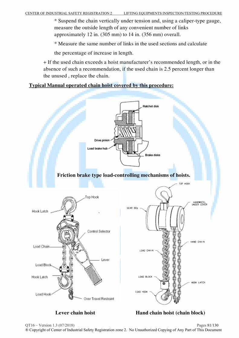
CENTER OF INDUSTRIAL SAFETY REGISTRATION 2 LIFTING EQUIPMENTS INSPECTION/TESTING PROCEDURE
QT16 – Version 1.3 (07/2018) Pages 81/130 ® Copyright of Center of Industrial Safety Registration zone 2. No Unauthorized Copying of Any Part of This Document
* Suspend the chain vertically under tension and, using a caliper-type gauge, measure the outside length of any convenient number of links approximately 12 in. (305 mm) to 14 in. (356 mm) overall.
* Measure the same number of links in the used sections and calculate
the percentage of increase in length.
+ If the used chain exceeds a hoist manufacturer’s recommended length, or in the absence of such a recommendation, if the used chain is 2.5 percent longer than the unused , replace the chain.
Typical Manual operated chain hoist covered by this procedure:
Friction brake type load-controlling mechanisms of hoists.
Lever chain hoist Hand chain hoist (chain block)

CENTER OF INDUSTRIAL SAFETY REGISTRATION 2 LIFTING EQUIPMENTS INSPECTION/TESTING PROCEDURE
QT16 – Version 1.3 (07/2018) Pages 82/130 ® Copyright of Center of Industrial Safety Registration zone 2. No Unauthorized Copying of Any Part of This Document
* NDT examination :
Inspector should be assigned suitable added NDT method such as magnetic particle or dye penetrant examination in accordance with EN 10228-1 or EN 10228-2(or ASTM E-709 or ASTM E-165) to inspect for surface intersecting discontinuities of hooks, links of manual operated chain hoists for his/her added inspection requirement.
III- Testing :
The manual operated chain hoists shall be subjected to test as follow:
III.1- Functioning test ( Recommended following requirements of DOE STD 1090 -2004 chapter 8)
- Check all functions of the hoist, including lifting and lowering without load.
- After testing unloaded, apply a load of at least 50 lb (23 kg) with hand chain hoist or 100lb(46kg) with lever chain hoists multiplied by the number of load-supporting parts of load chain to the hoist to check proper load control.
III.2- Static load test ( according to EN 13157:2004 +A 1:2009)
- The test load/test force is 150% rated capacity ( 1,5 SWL) if the SWL less than 20 tonnes and 125% rated capacity ( 1,25 SWL) if the SWL equal or greater 20tonnes.
- The chain hoists shall be capable of holding the test load/test force within 10minutes. Observe the test process.
- After this test, the chain hoist and it parts should be accepted only if found free from permanent deformations, cracks, or other defects.
III.3- Dynamic load test
- The test load/test force is 110% rated capacity ( 1,1 SWL)
- Lifting and lowering this load for 3 cycles. The chain hoist shall be capable of lifting and lowering this load normally. The load brake control shall stop and hold the load when the lever force (hand chain) is removed and the lever stroke is completed.
If satisfactory, the chain hoist shall be hard stamped in adequate position (or data plate) with test details and a report or certificate will be issued.
IV- Schedule of examination and test:
The manual operated chain hoist shall be periodically visual inspected, MT/PT examined with interval not exceeding 12 months (recommendation are 6 months ).
Periodic Load test should be caried out in accordance with recommendation of inspector or client requirements at least annually.
When the schedule requires a load test, any non-destructive examination and visual inspection shall both be carried out after the load test.

CENTER OF INDUSTRIAL SAFETY REGISTRATION 2 LIFTING EQUIPMENTS INSPECTION/TESTING PROCEDURE
QT16 – Version 1.3 (07/2018) Pages 83/130 ® Copyright of Center of Industrial Safety Registration zone 2. No Unauthorized Copying of Any Part of This Document
V- Report the result of inspection/testing:
- The inspector shall be completed and reported the result of inspection/testing in accordance with the form M16.15.1 and issued the inspection/loadtest certificate in accordance with the form M16.2.2 . - The inspection certificate shall be issued in accordance with the CISR’s procedure No. TT09.

CENTER OF INDUSTRIAL SAFETY REGISTRATION 2 LIFTING EQUIPMENTS INSPECTION/TESTING PROCEDURE
QT16 – Version 1.3 (07/2018) Pages 84/130 ® Copyright of Center of Industrial Safety Registration zone 2. No Unauthorized Copying of Any Part of This Document
PROCEDURE No : QT 16-DNV.16 INSPECTION, TESTING PROCEDURE FOR ELECTRIC/AIR POWERED CHAIN HOIST
A- SCOPE
This procedure provides general guidelines for competent person performing periodic electric/air powered hoist (that are not permanently mounted on overhead cranes) inspection and load testing services to ensure that it is capable of performing the it intended functions and fit for use.
The guidance and recommendation will meet the requirements of:
- EN 13157:2004+A1:2009 : Cranes - Safety - Hand powered cranes
- ASME B30.16 : Overhead Hoists (Underhung)
- DOE STD 1090 -2004 chapter 8 : Hoists
- TCVN 4244-2005 : Vietnamese lifting appliance safety standard.
B- INSPECTION/EXAMINATION/TESTING
I- Technical Requirements prior to inspection:
The inspector, who caried out the inspection/testing, shall be determined clearly the specifications of the object to be inspected/examined/tested, e.g SWL by means of review manufactured documents, last inspection/testing report.
II - Inspection/Examination Procedure
- Inspector shall carying out visual inspection, records identified information of specifications of the object to be inspected in to checklist as M16.16.1 form attached in this procedure (refer to it technical document or or check on marking for specifications).
- Adequate lighting and other facilities should be provided to caried out the inspection in all aspects of the object to be inspected.
- The object to be inspected should be hung up to carefully inspect, specially load chain, load- wire rope.
- Marking: Electric/air powered hoist shall be marked permanently and legibly on a non removable of the device with at least the following informations:
a) Electric powered hoists
* The rated capacity shall be permanently marked on the hoist or load block
* Name of manufacturer
* Manufacturer’s model or serial number
* Voltage of AC or DC power supply and phase/frequency of AC power supply.

CENTER OF INDUSTRIAL SAFETY REGISTRATION 2 LIFTING EQUIPMENTS INSPECTION/TESTING PROCEDURE
QT16 – Version 1.3 (07/2018) Pages 85/130 ® Copyright of Center of Industrial Safety Registration zone 2. No Unauthorized Copying of Any Part of This Document
* Electrical Circuit
* warning labels ( e.g electrical hazard, safety use..)
b)Air powered hoists
* The rated capacity shall be permanently marked on the hoist or load block
* Name of manufacturer
* Manufacturer’s model or serial number
* Rated air pressure.
* warning labels ( e.g presurize hazard, safety use..)
- The hoists shall be disassembled for internal examination for internal wear or damage if external appearance indicates there may be internal difficulty.
- Checked for functional and defects as follow:
+ Cracked or damaged housing, Incorrectly functioning ; Bolts, rivets, nuts, and pins for being loose or absent.
+ Controls and operating mechanisms, Hoist braking system for proper operation.
+ Load reeving for compliance with hoist manufacturer’s recommendations.
+ Cracked or worn drums or sheaves.
+ Worn, corroded, cracked, or distorted parts such as pins, bearings, shafts, gears, rollers locking, and clamping devices.
+ Excessive wear on motor or load brakes.
+ Excessive wear of chains, load sprockets, drums, sheaves, and chain stretch.
+ Deterioration or damage of end connections and terminations of wire rope, load chains.
+ Any wear exceeding 10% of the original section dimension of the hook or its load pin.
+ Hook-retaining nuts or collars and pins, welds, or riveting used to secure the
retaining members. Check that hook latch, if provided, is not missing and that it operates properly
+ Any cracks in hooks.
+ Hooks having more than 15 percent in excess of normal throat opening, or
more than 10 degree twist from the plane of the unbent hook (see hooks inspection procedure in this document for additional hook requirements).
+Warning labels for illegibility or absence.
+ Hoist braking system for proper operation.
+ Electrical apparatus for signs of pitting or any deterioration of controller contactors, limit switches, and push-button switches.
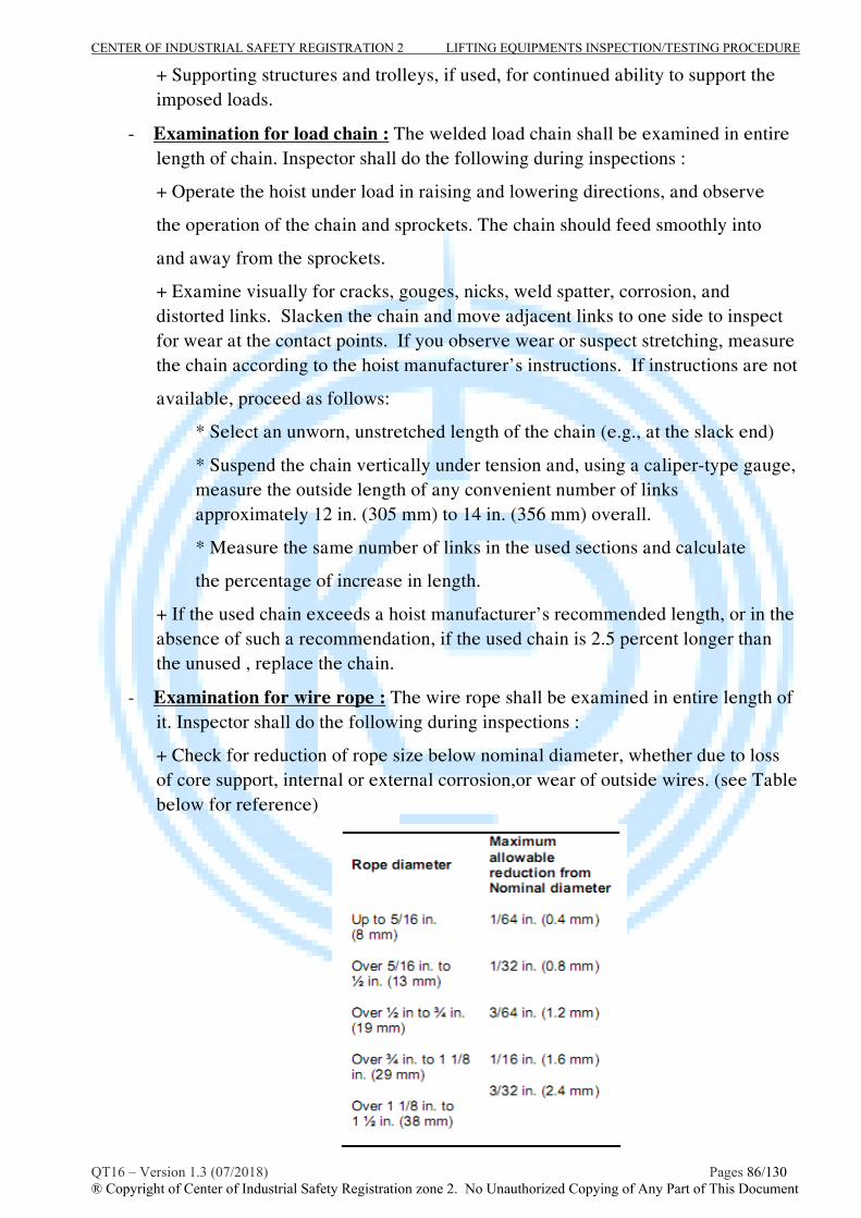
CENTER OF INDUSTRIAL SAFETY REGISTRATION 2 LIFTING EQUIPMENTS INSPECTION/TESTING PROCEDURE
QT16 – Version 1.3 (07/2018) Pages 86/130 ® Copyright of Center of Industrial Safety Registration zone 2. No Unauthorized Copying of Any Part of This Document
+ Supporting structures and trolleys, if used, for continued ability to support the imposed loads.
- Examination for load chain : The welded load chain shall be examined in entire length of chain. Inspector shall do the following during inspections :
+ Operate the hoist under load in raising and lowering directions, and observe
the operation of the chain and sprockets. The chain should feed smoothly into
and away from the sprockets.
+ Examine visually for cracks, gouges, nicks, weld spatter, corrosion, and distorted links. Slacken the chain and move adjacent links to one side to inspect for wear at the contact points. If you observe wear or suspect stretching, measure the chain according to the hoist manufacturer’s instructions. If instructions are not
available, proceed as follows:
* Select an unworn, unstretched length of the chain (e.g., at the slack end)
* Suspend the chain vertically under tension and, using a caliper-type gauge, measure the outside length of any convenient number of links approximately 12 in. (305 mm) to 14 in. (356 mm) overall.
* Measure the same number of links in the used sections and calculate
the percentage of increase in length.
+ If the used chain exceeds a hoist manufacturer’s recommended length, or in the absence of such a recommendation, if the used chain is 2.5 percent longer than the unused , replace the chain.
- Examination for wire rope : The wire rope shall be examined in entire length of it. Inspector shall do the following during inspections :
+ Check for reduction of rope size below nominal diameter, whether due to loss of core support, internal or external corrosion,or wear of outside wires. (see Table below for reference)

CENTER OF INDUSTRIAL SAFETY REGISTRATION 2 LIFTING EQUIPMENTS INSPECTION/TESTING PROCEDURE
QT16 – Version 1.3 (07/2018) Pages 87/130 ® Copyright of Center of Industrial Safety Registration zone 2. No Unauthorized Copying of Any Part of This Document
+ Check for numbers of broken outside wires and the distribution or concentration of such broken wires.
+ Worn outside wires.
+ Sections of rope that are normally hidden during inspection or maintenance procedures, such as parts passing over sheaves (these are points most subject to deterioration)
+ Corroded or broken wires at end connections.
+ Corroded, cracked, bent, worn, or improperly applied end connections.
+ Kinking, crushing, cutting, or unstranding.
+ The inspector should consider to replace wire rope in cases:
* In hoist ropes, 12 randomly distributed broken wires in one rope lay, or 4
broken wires in one strand in one rope lay.
* Wear of one-third of the original diameter of outside individual wires.
* Kinking, crushing, birdcaging, or any other damage resulting in distortion of the rope structure.
* Evidence of heat damage from any cause.
* Reductions from nominal diameter greater than those shown in Table above.
Typical electric/air powered hoists covered by this procedure:
electric/air powered welded chain hoists electric/air powered wire rope hoists
* NDT examination :
Inspector should be assigned suitable added NDT method such as magnetic particle or dye penetrant examination in accordance with EN 10228-1 or EN 10228-2(or ASTM E-709 or ASTM E-165) to inspect for surface intersecting discontinuities of hooks, links of the hoists for his/her added inspection requirement.

CENTER OF INDUSTRIAL SAFETY REGISTRATION 2 LIFTING EQUIPMENTS INSPECTION/TESTING PROCEDURE
QT16 – Version 1.3 (07/2018) Pages 88/130 ® Copyright of Center of Industrial Safety Registration zone 2. No Unauthorized Copying of Any Part of This Document
III- Testing :
The electric/air-powered hoists shall be subjected to test as follow:
III.1- Functioning test
- Check all functions of the hoist, including lifting and lowering without load.
- Check operation of brakes.
- Determine the trip-setting of limit devices by tests under no-load conditions. Conduct tests first by hand, if practical, and then under slowest speed obtainable. Test with increasing speeds up to maximum speed.
III.2- Static load test
- The test load/test force is 125% rated capacity ( 1,25 SWL)
- The chain hoists shall be capable of holding the test load/test force within 10minutes. Observe the test process.
- After this test, the hoist and it parts should be accepted only if found free from permanent deformations, cracks, or other defects.
III.3- Dynamic load test
- The test load/test force is 110% rated capacity ( 1,1 SWL)
- Lifting and lowering this load for 3 cycles. The hoist shall be capable of lifting and lowering this load normally. The load brake control shall stop and hold the load hook when controls are released; limit the speed of the load during lowering to a maximum of 120 percent of the rated lowering speed for the load being handled; stop and hold the load hook in the event of a complete power failure.
- If satisfactory, the hoist shall be hard stamped in adequate position (or data plate) with test details and a report or certificate will be issued.
IV- Schedule of examination and test:
The electric/air-powered hoists mentioned in this procedure shall be periodically visual inspected, MT/PT examined with interval not exceeding 12 months (recommendation are 6 months ). Periodic Load test should be caried out in accordance with recommendation of inspector or client requirements at least annually.
When the schedule requires a load test, any non-destructive examination and visual inspection shall both be carried out after the load test.
V- Report the result of inspection/testing:
- The inspector shall be completed and reported the result of inspection/testing in accordance with the form M16.16.1 and issued the inspection/loadtest certificate in accordance with the form M 16.2.2 - The inspection certificate shall be issued in accordance with the CISR’s procedure No. TT09.

CENTER OF INDUSTRIAL SAFETY REGISTRATION 2 LIFTING EQUIPMENTS INSPECTION/TESTING PROCEDURE
QT16 – Version 1.3 (07/2018) Pages 89/130 ® Copyright of Center of Industrial Safety Registration zone 2. No Unauthorized Copying of Any Part of This Document
PROCEDURE No : QT 16-DNV.17
INSPECTION, TESTING PROCEDURE FOR MAN-MADE FIBRE SLINGS
A- SCOPE
This procedure provides general guidelines for competent person performing the periodic
inspection and load testing of man-made web sling, round sling with SWL up to 40tonnes for general lifting service.
The guidance and recommendation will meet the requirements of :
- BS EN 1492-1, Textile slings- Safety, flat woven webbing slings;
- BS EN1492-2, Textile slings – Safety round slings, made of man-made fibre for general purpose use);
- AS 1353.1-1997 : Flat webling
- DOE-STD-1090-2001 Hoisting and Rigging.
B- INSPECTION/EXAMINATION/TESTING
I- Technical Requirements prior to inspection:
The inspector, who caried out the inspection/testing, shall be determined clearly the specifications of the fible sling, e.g WLL by means of review manufactured documents, last inspection/testing report.
II - Inspection/Examination Procedure
- Inspector shall carying out visual inspection, records identified information and specifications of sling in to checklist as M16.17.1 form attached in this procedure.
- Marking : The fible shall be marked by manufacturer at lests informations below:
The working load limit, on straight pull.
The material of sling, e.g. polyester, nilon, polypropylene..
Grade of fitting, where applicable
The nominal length
the traceability code or serial, model number
The sling shall be coloured with the color code in accordance with the table below (refer to EN 1492:2008 and AS 1353 :1997 )
Dimensional : sling should be hung up or stretched out on a level floor in a well-lighted area, remove all twists. Measure the sling length.
Round sling : The effective working length of a roundsling shall not differ from the nominal length by more than 2 % of the nominal length, when laid flat and pulled taut by hand tension and measured with a steel tape or rule graduated in increments of 1 mm.

CENTER OF INDUSTRIAL SAFETY REGISTRATION 2 LIFTING EQUIPMENTS INSPECTION/TESTING PROCEDURE
QT16 – Version 1.3 (07/2018) Pages 90/130 ® Copyright of Center of Industrial Safety Registration zone 2. No Unauthorized Copying of Any Part of This Document
Webing sling : The effective working length of a webing firble sling shall have an accuracy of ±3 percent of the nominal length.
- Visual inspection : The sling shall be cleaned prior to each inspection. adequate lighting should be provided and the sling should be examined throughout its length to detect any evidence of tear, excessive wear, fiber broken or external damage. Sling should be withdrawn from service if any of the following are observed:
* Acid or caustic burns.
* Melting or charring of any part of the surface.
* Snags, punctures, tears, or cuts.
* Heat damages
* Broken or worn stitches.
* Wear or elongation exceeding the amount recommended by the manufacturer.
* Distortion, cracks of fittings.
* Knots in any part.
* Missing or illegible sling identification.
Note1 : right measured method such as below

CENTER OF INDUSTRIAL SAFETY REGISTRATION 2 LIFTING EQUIPMENTS INSPECTION/TESTING PROCEDURE
QT16 – Version 1.3 (07/2018) Pages 91/130 ® Copyright of Center of Industrial Safety Registration zone 2. No Unauthorized Copying of Any Part of This Document
Table 2- EN 1492-2:2008 Working load limit and color code

CENTER OF INDUSTRIAL SAFETY REGISTRATION 2 LIFTING EQUIPMENTS INSPECTION/TESTING PROCEDURE
QT16 – Version 1.3 (07/2018) Pages 92/130 ® Copyright of Center of Industrial Safety Registration zone 2. No Unauthorized Copying of Any Part of This Document
Note 2 : Some typical defects of sling

CENTER OF INDUSTRIAL SAFETY REGISTRATION 2 LIFTING EQUIPMENTS INSPECTION/TESTING PROCEDURE
QT16 – Version 1.3 (07/2018) Pages 93/130 ® Copyright of Center of Industrial Safety Registration zone 2. No Unauthorized Copying of Any Part of This Document
Note 3 : Some typical firble sling
Webing sling
Round sling

CENTER OF INDUSTRIAL SAFETY REGISTRATION 2 LIFTING EQUIPMENTS INSPECTION/TESTING PROCEDURE
QT16 – Version 1.3 (07/2018) Pages 94/130 ® Copyright of Center of Industrial Safety Registration zone 2. No Unauthorized Copying of Any Part of This Document
III- Proof load test
When all the requirement inspections in the section II above, were assessed with satisfactory, the sling will be go on the lifting test stage.
Proof test will be caried out by using tension testing machine or lifting appliance with free test weight. Proof load test shall be applied on slings at the following circumstance: prior to critical use, all new or periodic inspection ;
Unless other requirements applies, assembled slings with fittings shall be subjected to a proof force test. The proof load are :
- Single-leg slings and endless slings : 2x SWL
- Multiple-leg bridle slings shall be applied to the individual legs with proof test load/force :
+ for 2-legs sling : 2 x (WLL All leg s sling )/1,4
+ for 3,4-legs sling : 2 x (WLL All leg s sling )/2,1
- Any master link to which multiple leg slings are connected shall be proof loaded to two times the force applied by the combined legs.
The accuracy of test load/test force within - 5% to 0% of stipulated values, the test load/test force shall be applied to each section without shock. The load shall be applied for a minimum of 5 minutes before measurements are taken.
IV- Schedule of examination and test:
Fibre slings shall be periodically inspected, examined and tested annually or before critical use.
V- Report the result of inspection/testing:
- The inspector shall be completed and reported the result of inspection/testing in accordance with the form M16.17.1 and issued the inspection/loadtest certificate in accordance with the form M16.3.2 . - The inspection certificate shall be issued in accordance with the CISR’s procedure No. TT09.

CENTER OF INDUSTRIAL SAFETY REGISTRATION 2 LIFTING EQUIPMENTS INSPECTION/TESTING PROCEDURE
QT16 – Version 1.3 (07/2018) Pages 95/130 ® Copyright of Center of Industrial Safety Registration zone 2. No Unauthorized Copying of Any Part of This Document
PROCEDURE No : QT 16-DNV.18
INSPECTION, TESTING PROCEDURE FOR BRACKETS (FABRICATED PAD-EYE, LIFITNG LUGS..)
A- SCOPE
This procedure provides general guidelines for competent person performing the periodic
inspection and load testing of brackets as lifting point, supporting point or securing point, mouted in lifting steel structure or offshore steel platform, for suspending, surporting or securing.
The guidance and recommendation will meet the requirements of :
- DNV No. 2.2.2 : Standard for certification of Lifting Appliance
- API RD 2A : Recommended practice for planing, designing, contructing fixed offshore platforms.
- APPEA, guidelines for lifting equipment (Australia Petroleum & Exploration Association Limited).
B- INSPECTION/EXAMINATION/TESTING
I- Technical Requirements prior to inspection:
The inspector, who caried out the inspection/testing, shall be determined clearly the specifications of the brackets , e.g WLL by means of review design technical documents, last inspection/testing report.
II - Inspection/Examination Procedure
- Inspector shall carying out visual inspection, records identified information and specifications of brackets in to checklist as M16.18.1 form attached in this procedure.
- Marking : The brackets shall be marked by manufacturer at lests informations below:
The working load limit, as stamped.
The identification, example ID No., Ser.No..
Grade of material (If any)
- Dimensional : The dimensions of brackets shall be carefully checked and It in compliance with design requirements document. In some case, when brackets are padeye, the inspector will use table 1 below for reference or caculate according to the Apendix D-DNV 2.7-1 to check the WLL of Padeye.
Ascertain that the direction of pull is correct.
Check the brackets alignment to the line of force for any tilt, with accuracy within +/-2.5 degree.

CENTER OF INDUSTRIAL SAFETY REGISTRATION 2 LIFTING EQUIPMENTS INSPECTION/TESTING PROCEDURE
QT16 – Version 1.3 (07/2018) Pages 96/130 ® Copyright of Center of Industrial Safety Registration zone 2. No Unauthorized Copying of Any Part of This Document
*

CENTER OF INDUSTRIAL SAFETY REGISTRATION 2 LIFTING EQUIPMENTS INSPECTION/TESTING PROCEDURE
QT16 – Version 1.3 (07/2018) Pages 97/130 ® Copyright of Center of Industrial Safety Registration zone 2. No Unauthorized Copying of Any Part of This Document
- Visual inspection : The brackets shall be cleaned prior to each inspection. adequate lighting should be provided and the brackets should be examined throughout its surface and welds to detect any evidence of cracks, excessive wear, deformation or other damage. brackets should be withdrawn from service for repair if any of the following are observed:
* Any deformation, distortion of padeye,
* excessive abration, corrosion.. which cause to loss metal section of brackets.
* cracks, cut, nick.. in welds and base
* excessive undercut, lack of penatration.. of welds.
* excessive damage for hole of padeye. Check if the hole is smooth enough so as not to create point load damage to the fitments.
* NDT examination :
Body and weld of brackets shall be subjected to magnetic particle or dye penetrant examination in accordance with EN 10228-1 or EN 10228-2(or ASTM E-709 or ASTM E-165) respectively to inspect for surface intersecting discontinuities.
III- Proof load test
When all the requirement inspections in the section II above, were assessed with satisfactory, the padeye will be go on to the lifting test stage.
Proof test will be caried out by using hydraulic pull tester or lifting appliance with free test weight.
Unless other requirements applies, the padeye shall be subjected to a proof force test. The proof test load for welded padeye to Item are (According to Apendix F-DNV Standard for certifiaction lifting appliance, 2008) :
Safety Working Load (SWL) Proof test load
Up to 20 tonnes 1,25 x SWL
20 – 50 tonnes SWL + 5 tonnes
Above 50 tonnes 1,1 x SWL
The accuracy of test load/test force within + 2% of stipulated values, the test load/test force shall be applied to each section without shock. The load shall be applied for a minimum of 5 minutes before measurements are taken.
IV- Schedule of examination and test:
In normal case, brackets shall be periodically inspected, examined and tested annually or before critical use.
V- Report the result of inspection/testing:

CENTER OF INDUSTRIAL SAFETY REGISTRATION 2 LIFTING EQUIPMENTS INSPECTION/TESTING PROCEDURE
QT16 – Version 1.3 (07/2018) Pages 98/130 ® Copyright of Center of Industrial Safety Registration zone 2. No Unauthorized Copying of Any Part of This Document
- The inspector shall be completed and reported the result of inspection/testing in accordance with the form M16.18.1 and issued the inspection/loadtest certificate in accordance with the form M16.1.2 . - The inspection certificate shall be issued in accordance with the CISR’s procedure No. TT09.
Typical proof load testing diagram for Brackets:

CENTER OF INDUSTRIAL SAFETY REGISTRATION 2 LIFTING EQUIPMENTS INSPECTION/TESTING PROCEDURE
QT16 – Version 1.3 (07/2018) Pages 99/130 ® Copyright of Center of Industrial Safety Registration zone 2. No Unauthorized Copying of Any Part of This Document
PROCEDURE No : QT 16 DNV .19 INSPECTION, TESTING PROCEDURE FOR
JAW WINCHS & DRUM WINCHS
A- SCOPE
This procedure provides general guidelines for competent person performing periodic inspection and load testing services for jaw winchs and Drum winchs to ensure that it is capable of performing the it intended function and fit for use.
The guidance and recommendation will meet the requirements of:
- BS EN 13157-2004: Cranes, Safety. Hand powered lifting equipment
- DOE STD 1090 -2004 chapter 8 : Hoists
- TCVN 4244-2005 : Vietnamese lifting appliance safety standard.
B- INSPECTION/EXAMINATION/TESTING
I- Technical Requirements prior to inspection:
The inspector, who caried out the inspection/testing, shall be determined clearly the specifications of the object to be inspected, e.g SWL by means of review manufactured documents, last inspection/testing report.
II - Inspection/Examination Procedure
- Inspector shall carying out visual inspection, records identified information of specifications of the object to be inspected in to checklist as M16.19.1 form attached in this procedure (refer to it technical document or or check on marking for specifications).
- Adequate lighting and other facilities should be provided to caried out the inspection in all aspects of the object to be inspected.
- Marking: jaw winchs and Drum winchs shall be marked permanently and legibly on a non removable of the device with at least the following informations:
+ For Drum Winchs
a) Name of the manufacturer;
c) Serial number or model
d) Rated capacity
e) size and quality of wire rope
f) the marking of the direction of movement
g)the marking of the direction of winding of the rope
h)the number of winding layers

CENTER OF INDUSTRIAL SAFETY REGISTRATION 2 LIFTING EQUIPMENTS INSPECTION/TESTING PROCEDURE
QT16 – Version 1.3 (07/2018) Pages 100/130 ® Copyright of Center of Industrial Safety Registration zone 2. No Unauthorized Copying of Any Part of This Document
+ For Jaw Winchs
a) Name of the manufacturer;
c) Serial number or model
d) Rated capacity
e) size and quality of wire rope
f) the marking of the direction of movement
- The object to be inspected should be disassembled for cleaning and internal examination for internal wear or damage if external appearance indicates there may be internal difficulty.
- Checked for functional and defects as follow:
TT Inspection Items Discription
For Jaw winchs For Drum winchs
1 Springs Visual examination Visual examination
2 Guarding covers Visual examination Visual examination
3 Hook-anchorage Visual examination Visual examination
4 Wire rope, fibre loaded rope
Visual examination Visual examination
5 Wire rope clamping machanism
Visual examination N/A
6 Wire rope terminations Visual examination Visual examination
7 Safety Device Visual examination Visual examination
8 Handling installation and fastening
Visual examination Visual examination
9 Drum-Drum flanges N/A Visual examination
10 Braking Visual check and Funtional test
Visual check and Funtional test
11 Marking Visual examination Visual examination
+ Cracked or damaged housing, Incorrectly functioning ; Bolts, rivets, nuts, and pins for being loose or absent.
+ Controls and operating mechanisms, Hoist braking system for proper operation. + Lever for bends, cracks, and the like
+ Load wire rope reeving for compliance with hoist manufacturer’s recommendations.
+ Worn, corroded, cracked, or distorted parts such as pins, bearings, shafts, gears, rollers locking, and clamping devices.

CENTER OF INDUSTRIAL SAFETY REGISTRATION 2 LIFTING EQUIPMENTS INSPECTION/TESTING PROCEDURE
QT16 – Version 1.3 (07/2018) Pages 101/130 ® Copyright of Center of Industrial Safety Registration zone 2. No Unauthorized Copying of Any Part of This Document
+ Excessive wear on load brakes.
+ Excessive wear of load sheaves.
+ Deterioration or damage of end connections and terminations load rope.
+ Any wear exceeding 10% of the original section dimension of the hook or its load pin.
+ Hook-retaining nuts or collars and pins, welds, or riveting used to secure the
retaining members. Check that hook latch, if provided, is not missing and that it operates properly
+ Any cracks in hooks.
+ Hooks having more than 15 percent in excess of normal throat opening, or
more than 10 degree twist from the plane of the unbent hook (see hooks inspection procedure in this document for additional hook requirements).
+Warning labels for illegibility or absence.
- examination for load wire rope, webling rope : The load rope shall be examined in all length of rope as requirement of relative inspection procedure in this document . Inspector shall do the following during inspections :
+ Operate the winch under light load in raising and lowering directions, and observe the operation of rope, drum and other . The rope should feed/worn smoothly into and away from the drum/clamping mechanism.
Typical Jaw winchs and drum winch covered by this procedure:

CENTER OF INDUSTRIAL SAFETY REGISTRATION 2 LIFTING EQUIPMENTS INSPECTION/TESTING PROCEDURE
QT16 – Version 1.3 (07/2018) Pages 102/130 ® Copyright of Center of Industrial Safety Registration zone 2. No Unauthorized Copying of Any Part of This Document
* NDT examination :
Inspector should be assigned suitable added NDT method such as magnetic particle or dye penetrant examination in accordance with EN 10228-1 or EN 10228-2(or ASTM E-709 or ASTM E-165) to inspect for surface intersecting discontinuities of hooks, links of winchs for his/her added inspection requirement.
III- Testing :
The winch shall be subjected to test as follow:
III.1- Functioning test
- Check all functions of the winch, including lifting and lowering with light load is 10% of rated load.
III.2- Static load test ( according to EN 13157:2004 +A 1:2009)
- The test load/test force is 150% rated capacity ( 1,5 SWL) if the SWL less than 20 tonnes and 125% rated capacity ( 1,25 SWL) if the SWL equal or greater 20tonnes.
- The winchs shall be capable of holding the test load/test force within 10minutes. Observe the test process.
- After this test, the winchs and it parts should be accepted only if found free from permanent deformations, cracks, or other defects.

CENTER OF INDUSTRIAL SAFETY REGISTRATION 2 LIFTING EQUIPMENTS INSPECTION/TESTING PROCEDURE
QT16 – Version 1.3 (07/2018) Pages 103/130 ® Copyright of Center of Industrial Safety Registration zone 2. No Unauthorized Copying of Any Part of This Document
III.3- Dynamic load test
- The test load/test force is 110% rated capacity ( 1,1 SWL)
- Lifting and lowering this load for 3 cycles. The winchs shall be capable of lifting and lowering this load normally. The load brake/clamping mechanism control shall stop and hold the load when the lever force is removed and the lever stroke is completed.
If satisfactory, the winchs shall be hard stamped in adequate position (or data plate) with test details and a report or certificate will be issued.
IV- Schedule of examination and test:
The jaw winchs and drum winch shall be periodically visual inspected, MT/PT examined with interval not exceeding 12 months (recommendation are 6 months ).
Periodic Load test should be caried out in accordance with recommendation of inspector or client requirements at least annually.
When the schedule requires a load test, any non-destructive examination and visual inspection shall both be carried out after the load test.
V- Report the result of inspection/testing:
- The inspector shall be completed and reported the result of inspection/testing in accordance with the form M16.19.1 and issued the inspection/loadtest certificate in accordance with the form M16.2.2 . - The inspection certificate shall be issued in accordance with the CISR’s procedure No. TT09.

CENTER OF INDUSTRIAL SAFETY REGISTRATION 2 LIFTING EQUIPMENTS INSPECTION/TESTING PROCEDURE
QT16 – Version 1.3 (07/2018) Pages 104/130 ® Copyright of Center of Industrial Safety Registration zone 2. No Unauthorized Copying of Any Part of This Document
PROCEDURE No : QT 16.20 INSPECTION, TESTING PROCEDURE FOR
LIFTING JACKS( Pneumatic, machanical, hydraulic jacks)
A- SCOPE
This part provides general guidelines for competent person performing periodic lifting jacks (hydraulic jacks, mechanical ratchet jacks, hand or power operated mechanical screw jacks) inspection and load testing services to ensure that it is capable of performing the it intended function and fit for use.
The guidance and recommendation will meet the requirements of:
- ASME B30.1 : Lifting Jack
- EN 1494-2000 : Mobile or movable jacks and associated lifting equipment
B- INSPECTION/EXAMINATION/TESTING
I- Technical Requirements prior to inspection:
The inspector, who caried out the inspection/testing, shall be determined clearly the specifications of the lifting jacks, e.g rated capacity by means of review manufactured documents, last inspection/testing report.
II - Inspection/Examination Procedure
- Inspector shall carying out visual inspection, records identified information of specifications of lifting jacks in to checklist as M16.20.1 form attached in this procedure (refer to it technical document or check on marking for specifications).
- Adequate lighting and other facilities should be provided to caried out the inspection in all aspects of lifting jacks.
- Marking: Lifting jacks shall be marked permanently and legibly on a non removable of the device with at least the following informations:
a) Name and address of the manufacturer or supplier;
b) year of construction;
c) Serial number or batch code
d) Rated load
e) hint to residual risks.
f) Where the rated load depend on the configuration of the jack, the rated load shall be shown for each configulation on a load plate, preferably in diagrammatic form or by means of load table.
- The jack shall be disassembled for cleaning and internal examination for internal wear or damage if external appearance indicates there may be internal difficulty.
- Checked for functional and defects as follow:

CENTER OF INDUSTRIAL SAFETY REGISTRATION 2 LIFTING EQUIPMENTS INSPECTION/TESTING PROCEDURE
QT16 – Version 1.3 (07/2018) Pages 105/130 ® Copyright of Center of Industrial Safety Registration zone 2. No Unauthorized Copying of Any Part of This Document
+ Cracked or damaged housing, Incorrectly functioning swivel heads or adj.screw
+ Improper engagement or extreme wear of pawl and rack
+ Chipped, cracked, or broken rack teeth
+ Excessive wear, bending, or other damage to threads
+ Leaking hydraulic fluid
+Scored or damaged plunger, piston rod
+ Improperly functioning swivel heads and caps
+ Loose bolts or rivets
+Damaged or improperly assembled accessory equipment
+ Other items as specified in manufacturer’s instruction which may affect operation.
Typical lifting Jack covered by this procedure:
Mechanical ratchet jacks Hand or power operated mechanical screw jacks
Hydraulic Jack Hydraulic Jack with load indicator

CENTER OF INDUSTRIAL SAFETY REGISTRATION 2 LIFTING EQUIPMENTS INSPECTION/TESTING PROCEDURE
QT16 – Version 1.3 (07/2018) Pages 106/130 ® Copyright of Center of Industrial Safety Registration zone 2. No Unauthorized Copying of Any Part of This Document
* NDT examination :
Inspector should be assigned suitable added NDT method such as magnetic particle or dye penetrant examination in accordance with EN 10228-1 or EN 10228-2(or ASTM E-709 or ASTM E-165) to inspect for surface intersecting discontinuities of jacks as his/her requirement.
III- Testing :
The lifting jack shall be subjected to test as follow:
III.1 : Hydraulic jack
1- functioning test
- Check the correct operation of the controls operate unload jack through one commplete cycle
- Place the rated load distributed as specified by the manufacture on the jack, operate it through one cycle. Record the maximum pressure in the steady state for hydraulic and pneumatic jacks .
- Record the time taken to fully lower the jack whire carrying the rated load. The average lower speed shall not exceed 0,15m/s.
- Leave the jack still carying rated load, fully raised for 10 minutes. Measure and record the vetical descent of the jack in this time. Generally this descent shall not exceed 2mm, on hydraulic jack using machanical linkages (e.g. trolley jacks) maximum descent shall not exceed 5mm.
2- static load test
- Lift the lift pad without the load to haft stroke position. Exposed the jack positioned vertically to a vertical load of :
150 % of the rated load in case of manual operated machanical jack.
150 % of maximum possible load in all other cases.
- Under this condittion (height adatation spindle turned to highest position), it shall be posible to carying the load, to sustain it for a period of 15 minutes and to lower it.
- After this test, the tested jack shall be dismantled to inspect for any permanent deformation for all parts.
3- dynamic load test
- For the following test, the pressure relief valve of hydraulic and pneumatic jack shall be neutralized:
- Position the jack vertically and apply the vertical load of:
110 % of the rated load in case of manual operated machanical jack.
110 % of maximum possible load in all other cases.

CENTER OF INDUSTRIAL SAFETY REGISTRATION 2 LIFTING EQUIPMENTS INSPECTION/TESTING PROCEDURE
QT16 – Version 1.3 (07/2018) Pages 107/130 ® Copyright of Center of Industrial Safety Registration zone 2. No Unauthorized Copying of Any Part of This Document
- the jack shall then be capable of lifting and lowering this load through it entire stroke as for intended use.
- After this test, the tested jack shall be dismantled to inspect for any permanent deformation for all parts.
After each test, all parts of the jack should be accepted only if found free from permanent deformation, cracks, fluid leakage, or other defects.
If satisfactory, the jack shall be hard stamped in adequate position with test details and a report or certificate will be issued.
IV- Schedule of examination and test:
The jack shall be periodically visual inspected, MT/PT examined with interval not exceeding 12 months (recommendation are 6 months ).
Periodic Load test should be caried out in accordance with recommendation of inspector or client requirements at least annually.
When the schedule requires a load test, any non-destructive examination and visual inspection shall both be carried out after the load test.
V- Report the result of inspection/testing:
- The inspector shall be completed and reported the result of inspection/testing in accordance with the form M16.20.1 and issued the inspection/loadtest certificate in accordance with the form M16.2.2 - The inspection certificate shall be issued in accordance with the CISR’s procedure No. TT09.

CENTER OF INDUSTRIAL SAFETY REGISTRATION 2 LIFTING EQUIPMENTS INSPECTION/TESTING PROCEDURE
QT16 – Version 1.3 (07/2018) Pages 108/130 ® Copyright of Center of Industrial Safety Registration zone 2. No Unauthorized Copying of Any Part of This Document
PROCEDURE No : QT 16-DNV.21 INSPECTION, TESTING PROCEDURE FOR
SHIPBOARD CRANES AND OFFSHORE CRANES
A- SCOPE
This procedure provides general guidelines for competent person performing periodic inspection and load testing services for shipboard and offshore cranes (testing crane as a unit) to ensure that it is capable of performing the it intended functions and fit for use.
The guidance and recommendation will meet the requirements of:
- ABS Guide for Certification of Lifting appliances – July 2007
- API - 2D: Offshore crane maintenance and inspection
- TCVN 6968-2001: Rules for offshore lifting appliances.
- TCVN 6272-2003: Rules for cargo handling appliances of Ships
B- INSPECTION/EXAMINATION/TESTING
I- Technical Requirements prior to inspection:
The inspector, who caried out the inspection/testing, shall be determined clearly the specifications of the object to be inspected/examined/tested, e.g SWL by means of review manufactured documents, last inspection/testing report.
II - Inspection/Examination Procedure
- Inspector shall carying out visual inspection, records identified information of specifications of the object to be inspected in to checklist as M16.16.1 form attached in this procedure (refer to it’s technical document or check on marking for specifications).
- Adequate lighting and other facilities should be provided to caried out the inspection in all aspects of the object to be inspected.
- The crane to be inspected should be in normal operation condition.
- Marking: the crane shall be marked permanently and legibly on a non removable of the device with at least the following informations:
* Name of manufacturer
* Manufacturer’s model or serial number
* The SWL and max/min working radius (or span) shall be permanently marked on the boom.
* Load chart in control position.
* Voltage of AC or DC power supply and phase/frequency of AC power supply should be noted in electrical equipment/system .
* warning labels ( e.g electrical hazard, safety use..)

CENTER OF INDUSTRIAL SAFETY REGISTRATION 2 LIFTING EQUIPMENTS INSPECTION/TESTING PROCEDURE
QT16 – Version 1.3 (07/2018) Pages 109/130 ® Copyright of Center of Industrial Safety Registration zone 2. No Unauthorized Copying of Any Part of This Document
- The cranes and it’s importance parts should be disassembled for internal examination for internal wear or damage if external appearance indicates there may be internal difficulty (folowing requirement of inspector).
- Checked for functional and defects as follow:
The metal structure : The main structure of crane such as Boom, girder, A-frame, pedestal, padeyes… shall be visually inspection for corrosion, mechanical damage, injurious deformation. The primary structure shall be in good situation, any steelwork that has suffered significant (greater than 10%) metal loss through corrosion is to be replaced.
Operating machanisms : All working machanisms of crane such as hoisting, slewing, luffering,.. and it control system shall be visually inspection for assambly situation, corrosion of parts, mechanical damage, injurious deformation and operation situation as follow:
+ Cracked or damaged housing, Incorrectly functioning ; Bolts, rivets, nuts, and pins for being loose or absent.
+ Controls and operating mechanisms, Hoist braking system for proper operation.
+ Load reeving for compliance with hoist manufacturer’s recommendations.
+ Cracked or worn winch drums or sheaves.
+ Worn, corroded, cracked, or distorted parts such as pins, bearings, shafts clamping devices…
+ Excessive wear on brakes drum and lines.
+ Deterioration or damage of end connections and terminations of wire rope, load chains.
+ Any wear exceeding 10% of the original section dimension of the hook or its load pin.
+ Hook-retaining nuts or collars and pins, welds, or riveting used to secure the
retaining members. Check that hook latch, if provided, is not missing and that it operates properly
+ Any cracks in hooks.
+ Hooks having more than 15 percent in excess of normal throat opening, or
more than 10 degree twist from the plane of the unbent hook (see hooks inspection procedure in this document for additional hook requirements).
+Warning labels for illegibility or absence.
+ Hoist braking system for proper operation.
+ Electrical apparatus for signs of pitting or any deterioration of controller contactors, limit switches, and push-button switches.
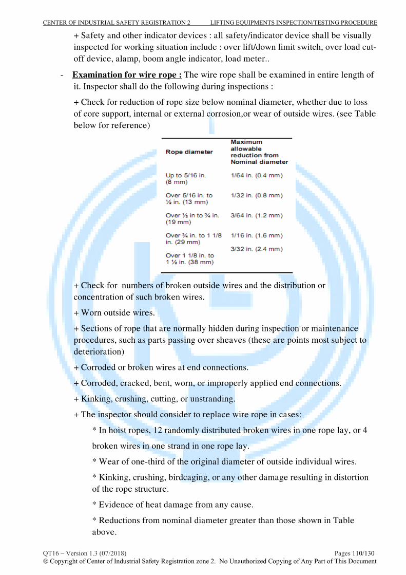
CENTER OF INDUSTRIAL SAFETY REGISTRATION 2 LIFTING EQUIPMENTS INSPECTION/TESTING PROCEDURE
QT16 – Version 1.3 (07/2018) Pages 110/130 ® Copyright of Center of Industrial Safety Registration zone 2. No Unauthorized Copying of Any Part of This Document
+ Safety and other indicator devices : all safety/indicator device shall be visually inspected for working situation include : over lift/down limit switch, over load cut-off device, alamp, boom angle indicator, load meter..
- Examination for wire rope : The wire rope shall be examined in entire length of it. Inspector shall do the following during inspections :
+ Check for reduction of rope size below nominal diameter, whether due to loss of core support, internal or external corrosion,or wear of outside wires. (see Table below for reference)
+ Check for numbers of broken outside wires and the distribution or concentration of such broken wires.
+ Worn outside wires.
+ Sections of rope that are normally hidden during inspection or maintenance procedures, such as parts passing over sheaves (these are points most subject to deterioration)
+ Corroded or broken wires at end connections.
+ Corroded, cracked, bent, worn, or improperly applied end connections.
+ Kinking, crushing, cutting, or unstranding.
+ The inspector should consider to replace wire rope in cases:
* In hoist ropes, 12 randomly distributed broken wires in one rope lay, or 4
broken wires in one strand in one rope lay.
* Wear of one-third of the original diameter of outside individual wires.
* Kinking, crushing, birdcaging, or any other damage resulting in distortion of the rope structure.
* Evidence of heat damage from any cause.
* Reductions from nominal diameter greater than those shown in Table above.

CENTER OF INDUSTRIAL SAFETY REGISTRATION 2 LIFTING EQUIPMENTS INSPECTION/TESTING PROCEDURE
QT16 – Version 1.3 (07/2018) Pages 111/130 ® Copyright of Center of Industrial Safety Registration zone 2. No Unauthorized Copying of Any Part of This Document
Typical crane covered by this procedure:

CENTER OF INDUSTRIAL SAFETY REGISTRATION 2 LIFTING EQUIPMENTS INSPECTION/TESTING PROCEDURE
QT16 – Version 1.3 (07/2018) Pages 112/130 ® Copyright of Center of Industrial Safety Registration zone 2. No Unauthorized Copying of Any Part of This Document

CENTER OF INDUSTRIAL SAFETY REGISTRATION 2 LIFTING EQUIPMENTS INSPECTION/TESTING PROCEDURE
QT16 – Version 1.3 (07/2018) Pages 113/130 ® Copyright of Center of Industrial Safety Registration zone 2. No Unauthorized Copying of Any Part of This Document
* NDT examination :
Inspector should be assigned suitable added NDT method such as magnetic particle or dye penetrant examination in accordance with EN 10228-1 or EN 10228-2(or ASTM E-709 or ASTM E-165) to inspect for surface intersecting discontinuities of hooks, links of the crane structure and it parts for his/her added inspection requirement.
III- Testing :
The crane shall be subjected to test as follow:
III.1- Functioning test
- Check all functions of the hoist, slewing, luffering include lifting and lowering without load.
- Check operation of brakes.
- Determine the trip-setting of limit devices by tests under no-load conditions. Conduct tests first by hand, if practical, and then under slowest speed obtainable. Test with increasing speeds up to maximum speed.
III.2- Proff load test
Proof Test Load
The crane is to be tested onboard to the following proof loads:

CENTER OF INDUSTRIAL SAFETY REGISTRATION 2 LIFTING EQUIPMENTS INSPECTION/TESTING PROCEDURE
QT16 – Version 1.3 (07/2018) Pages 114/130 ® Copyright of Center of Industrial Safety Registration zone 2. No Unauthorized Copying of Any Part of This Document
Proof load testing and inspection
Unless otherwise, the Proof Load Test is to be carried out using movable known weights. Booms shall be tested at the minimum, maximum and intermediate radii. These radii are to be stated on the Certificate of Test together with the proof loads used. Test rating conditions most likely to represent all intended service should be selected. The proof load should be lifted and held for at least five minutes. The Proof Load Test should include
hoisting and lowering of the main hook load, auxiliary hook load and boom; slewing (swinging) and luffing; test of safety, fail-safe and limiting devices and load-moment and boom-angle indicators.
For testing subsequent to the Original Test, in the case of hydraulic cranes, when owing to built-in arrangements for limitation of pressure, or in electric drive cranes when there is built-in load limiting control, it is impossible to lift the required proof-load, it will be sufficient to lift the greatest possible load. When the load lifted is less than the proof test load required in table 1 above, a notation is to be made on the certificate that this load was the maximum possible load. However, in no case is the test load to be less than the safe working load stated on the certificate. It will also be noted on the certificate that the load was limited by a built in electric or hydraulic load limit control and that the adjusting devices or relief valves were found sealed.
After being tested, each crane, together with all critical accessories, is to be examined to see whether any part has been damaged or permanently deformed by the test. The inspector should examine at least the following items:
i) Foundation, main steel structure (mast, boom, pedestal...)
ii) Sheaves and rope guides
iii) Wire ropes including end connections
iv) Hoist machinery, brakes and clutches
v) Hooks
vi) Slewing assembly and bolting arrangements

CENTER OF INDUSTRIAL SAFETY REGISTRATION 2 LIFTING EQUIPMENTS INSPECTION/TESTING PROCEDURE
QT16 – Version 1.3 (07/2018) Pages 115/130 ® Copyright of Center of Industrial Safety Registration zone 2. No Unauthorized Copying of Any Part of This Document
- If satisfactory, the crane shall be hard stamped in adequate position (or data plate) with test details and a report or certificate will be issued.
IV- Schedule of examination and test:
The crane mentioned in this procedure shall be periodically visual inspected, MT/PT examined with interval not exceeding 12 months. Periodic Load test should be carried out in accordance with recommendation of inspector or client requirements but with interval not exceeding 48 months.
When the schedule requires a load test, any non-destructive examination and visual inspection shall both be carried out after the load test.
V- Report the result of inspection/testing:
- The inspector shall be completed and reported the result of inspection/testing in accordance with the form M16.21.1 and issued the inspection/loadtest certificate in accordance with the form M 16.2.2 - The inspection certificate shall be issued in accordance with the CISR’s procedure No. TT09.

CENTER OF INDUSTRIAL SAFETY REGISTRATION 2 LIFTING EQUIPMENTS INSPECTION/TESTING PROCEDURE
QT16 – Version 1.3 (07/2018) Pages 116/130 ® Copyright of Center of Industrial Safety Registration zone 2. No Unauthorized Copying of Any Part of This Document
PROCEDURE No : QT 16 DNV .22 INSPECTION, TESTING PROCEDURE FOR
DONUT PERSONAL RESCUE SYSTEM
A- SCOPE
This procedure provides general guidelines for competent person performing periodic inspection and load testing services for “donut personal rescue system” to ensure that it is capable of performing it’s intended function and fit for use.
The “DPRS- donut personal rescue system” includes: Descender device; Harness and connectors.
The guidance and recommendation will meet the requirements of: - IM/DON/96: Instruction manual for donut personal rescue system.
- BS EN 341:1993 - Personal protective equipment against falls from a height. Descender devices
- BSEN 362:1993 - Personal protective equipment against falls from a height. Connectors
- BS EN 365: 1993- Personal protective equipment against falls from a height. General requirement for instructions for use and for marking
B- INSPECTION/EXAMINATION/TESTING
I- Technical Requirements prior to inspection:
The inspector, who caried out the inspection/testing, shall be determined clearly the specifications of the object to be inspected, e.g SWL by means of review manufactured documents, last inspection/testing report.
II - Inspection/Examination Procedure
- Inspector shall be carried out visual inspection, records identified information of specifications of the object to be inspected in to checklist as M16.22.1 form attached in this procedure (refer to it technical document or check on marking for specifications).
- Adequate lighting and other facilities should be provided to carry out the inspection in all aspects of the object to be inspected.
- Marking/Warning: Donut Descender shall be marked permanently and legibly on a non removable of the device with at least the following information:
a)Manufacturer or supplier;
c) Fabrication number/model;
d) Year of production ;
e) descender device class (A,B,C,D);
f) Maximum descent height;
g)Maximum descent load

CENTER OF INDUSTRIAL SAFETY REGISTRATION 2 LIFTING EQUIPMENTS INSPECTION/TESTING PROCEDURE
QT16 – Version 1.3 (07/2018) Pages 117/130 ® Copyright of Center of Industrial Safety Registration zone 2. No Unauthorized Copying of Any Part of This Document
attached to the each descender device there must be a short version of instruction for use.
- The vacuum packaging should be inspected for signs of damage, leaking or ingress of water, chemical etc..
- The object to be inspected should be disassembled for cleaning and thorough inspection/examination for all internal parts.
- Checked for functional and defects as follow:
TT Inspection Items Discription
1 Springs Visual examination
2 Guarding covers Visual examination
3 Hook-anchorage, shackle Visual examination
4 Wire rope, fibre loaded rope
Visual examination 4.1.1-4.1.4 BS EN 341:1993
5 Wire rope clamping mechanism Visual examination
6 Wire rope terminations
Visual examination 4.1.5 BS EN 341:1993
7 Hand operated, Safety Device
Visual examination 4.2 BS EN 341:1993
8 installation and fastening Visual examination
9 Braking Visual check and Functional test
10 Marking Visual examination
+ Cracked or damaged housing, Incorrectly functioning; Bolts, rivets, nuts, and pins for being loose or absent.
+ Controls and operating mechanisms, braking system for proper operation.
+ Worn, corroded, cracked, or distorted parts such as pins, bearings, shafts, gears, rollers locking, and clamping devices.
+ Excessive corrosion/wear on load brakes.
+ Excessive corrosion/wear of load sheaves.
+ Deterioration or damage of end connections and terminations load rope.
+ Any wear exceeding 10% of the original section dimension of the hook or its load pin.
+ Hook-retaining nuts or collars and pins, welds, or riveting used to secure the

CENTER OF INDUSTRIAL SAFETY REGISTRATION 2 LIFTING EQUIPMENTS INSPECTION/TESTING PROCEDURE
QT16 – Version 1.3 (07/2018) Pages 118/130 ® Copyright of Center of Industrial Safety Registration zone 2. No Unauthorized Copying of Any Part of This Document
retaining members. Check that hook latch, if provided, is not missing and that it operates properly
+ Any cracks in hooks.
+ Hooks having more than 15 percent in excess of normal throat opening, or
more than 10 degree twist from the plane of the unbent hook (see hooks inspection procedure in this document for additional hook requirements).
+Warning labels for illegibility or absence.
- examination for load wire rope, webling rope : The load rope shall be examined in all length of rope as requirement of relative inspection procedure in this document .
Typical Donut personal rescue system covered by this procedure:

CENTER OF INDUSTRIAL SAFETY REGISTRATION 2 LIFTING EQUIPMENTS INSPECTION/TESTING PROCEDURE
QT16 – Version 1.3 (07/2018) Pages 119/130 ® Copyright of Center of Industrial Safety Registration zone 2. No Unauthorized Copying of Any Part of This Document
* NDT examination :
Inspector should be assigned suitable added NDT method such as magnetic particle or dye penetrant examination in accordance with EN 10228-1 or EN 10228-2(or ASTM E-709 or ASTM E-165) to inspect for surface intersecting discontinuities of hooks, links.. for his/her added inspection requirement.
III- Testing :
The DPRS shall be subjected to test as follow:
III.1- Descender device
Functioning test for descender device according to requirement of BS EN 341:1993 clause 5.7, as follow:
- Descent height of test: design descent height of device.
- Test load: maximum load is 150 kg for class A,B,C and 100 kg for class D ; Minimum load is 30kg for all class.
- The descender device shall be load tested for both maximum and minimum load.
- Testing method:

CENTER OF INDUSTRIAL SAFETY REGISTRATION 2 LIFTING EQUIPMENTS INSPECTION/TESTING PROCEDURE
QT16 – Version 1.3 (07/2018) Pages 120/130 ® Copyright of Center of Industrial Safety Registration zone 2. No Unauthorized Copying of Any Part of This Document
Test load: Using the spherical type test bag (made from PVC) contained smaller bags of steel balls. maximum accuracy of test load is 2%.
Anchorage point: using suitable crane (SWL, lifting height..), the attached hook of descender device should be anchored to crane hook.
Test control device: Using wet device and wet rope to control the hand operated device in descender from ground.
Test procedure:
Install Donut personal rescue system as manufacturer instruction.
Put the test load in to harness and secured it to the harness.
Anchor the attached hook of descender to the hook of crane.
Using the crane to hoist the descender to the test height (design descent height of descender device).
Pull the wet rope to control the wet device to release the clamping device in descender and lowering the descender c/w test load and counter lowering time.
Calculate the average of descent velocity base on the descent height and descent time. The average descent velocity for class A,B,C shall be kept between 0,5 m/s and 2 m/s; for the D class device it must be possible to maintain a descent velocity of a maximum 2m/s.
The temperature of descender wire strop and other touched parts after test are not exceed 480C.
After this test, the DPRS and it parts should be accepted only if found free from permanent deformations, cracks, or other defects.
III.2- Connectors
Please refer to inspection/testing No. QT 16 DNV .3 for detail.
III.3- Harness: without load test.
If satisfactory, the DPRS shall be tagged with suitable tag name and a report/certificate will be issued.
IV- Re packing and vacuum packing for the units.
After inspection and testing with satisfactory result, all of descender device and attached parts shall be re-packing and vacuum packing as instruction of manufacture. The vacuum bag shall be vacuumed to maximum 50mm Hg.
V- Schedule of examination and test:

CENTER OF INDUSTRIAL SAFETY REGISTRATION 2 LIFTING EQUIPMENTS INSPECTION/TESTING PROCEDURE
QT16 – Version 1.3 (07/2018) Pages 121/130 ® Copyright of Center of Industrial Safety Registration zone 2. No Unauthorized Copying of Any Part of This Document
The descender c/w accessories shall be periodically visual inspected, MT/PT examined with interval not exceeding 12 months.
Periodic Load test should be caried out in accordance with recommendation of inspector or client requirements at least 2 years.
When the schedule requires a load test, any non-destructive examination and visual inspection shall both be carried out after the load test.
V- Report the result of inspection/testing:
- The inspector shall be completed and reported the result of inspection/testing in accordance with the form M16.22.1 and issued the inspection/loadtest certificate in accordance with the form M 16.2.2. - The inspection certificate shall be issued in accordance with the CISR’s procedure No. TT09.

CENTER OF INDUSTRIAL SAFETY REGISTRATION 2 LIFTING EQUIPMENTS INSPECTION/TESTING PROCEDURE
QT16 – Version 1.3 (07/2018) Pages 122/130 ® Copyright of Center of Industrial Safety Registration zone 2. No Unauthorized Copying of Any Part of This Document
PROCEDURE No : QT 16 DNV .23 INSPECTION, TESTING PROCEDURE FOR
CAPSTAN C/W QUICK RELEASE HOOKS(QRH)
A- SCOPE
This procedure provides general guidelines for competent person performing periodic inspection and load testing services for Capstan c/w Quick release hook (QRH) to ensure that it is capable of performing the its intended function and fit for use.
The guidance and recommendation will meet the requirements of:
+ BSEN 13155, Cranes – Safety-Non fixed load lifting attachments;
+ ASME B30.10- Hooks.
+ TCVN 4244-2005: Vietnamese lifting appliance safety standard.
B- INSPECTION/EXAMINATION/TESTING
I- Technical Requirements prior to inspection:
The inspector, who carry out the inspection/testing, shall be determined clearly the specifications of the object to be inspected, e.g SWL by means of review manufactured documents, last inspection/testing report.
II - Inspection/Examination Procedure
- Inspector shall carry out visual inspection, records identified information of specifications of the object to be inspected in to checklist as M16.23.1 form attached in this procedure (refer to its technical document or checking on data plate for specifications).
- Adequate lighting and other facilities should be provided to carry out the inspection in all aspects of the object to be inspected.
- Marking: the tested object shall be marked permanently and legibly on a non removable of the device with at least the following information:
a) Name of the manufacturer;
b) Serial number or model;
c) Rated capacity;
d) The marking of the direction of movement
- The object to be inspected should be disassembled for cleaning and internal examination for internal wear or damage if external appearance indicates there may be internal difficulty.
- Checking for functional and defects as follow:
TT Inspection Items Description
Type of check NDT

CENTER OF INDUSTRIAL SAFETY REGISTRATION 2 LIFTING EQUIPMENTS INSPECTION/TESTING PROCEDURE
QT16 – Version 1.3 (07/2018) Pages 123/130 ® Copyright of Center of Industrial Safety Registration zone 2. No Unauthorized Copying of Any Part of This Document
1 Support structure Visual examination
2 Capstan lead Visual examination
3 Hold down Bolt/nut Visual examination
4 Capstan motor and gear box Visual examination
5 Capstan Brake Visual examination
6 Capstan control box
Visual examination Electrical safety examination
7 Footswitch Visual examination/
functional test
8 QRH Visual examination
9 Hook casting (Item 1) Visual
examination+NDT MT/PT
10 Primary trip lever (Item 3)
Visual check and functional test
11 Manual release lever(Item 4)
Visual check and functional test
12 Cam roll bearing(Item 5) Visual examination
13 Pivot pin (Item 9) Visual examination
14 Load pin/loadcell Visual examination
15 Marking Visual examination
The visual check shall be carried out for:
+ Cracks or damage of housing, incorrect assembly; Bolts, rivets, nuts, pins for being loose or absent.
+ Controls and operating mechanisms, Hoist braking system for proper operation. + Levers for bends, cracks, and the like
+ Worn, corroded, cracked, or distorted parts such as pins, bearings, shafts, gears, rollers locking, and clamping devices.
+ Excessive wear on load brakes.
+ Excessive wear of Capstan.
+ Any wear exceeding 10% of the original section dimension of the hook or its load pin.
+ Hook-retaining nuts or collars and pins, welds, or riveting used to secure the retaining members. Check that hook latch, if provided, is not missing and that it operates properly
+ Any cracks in hooks.
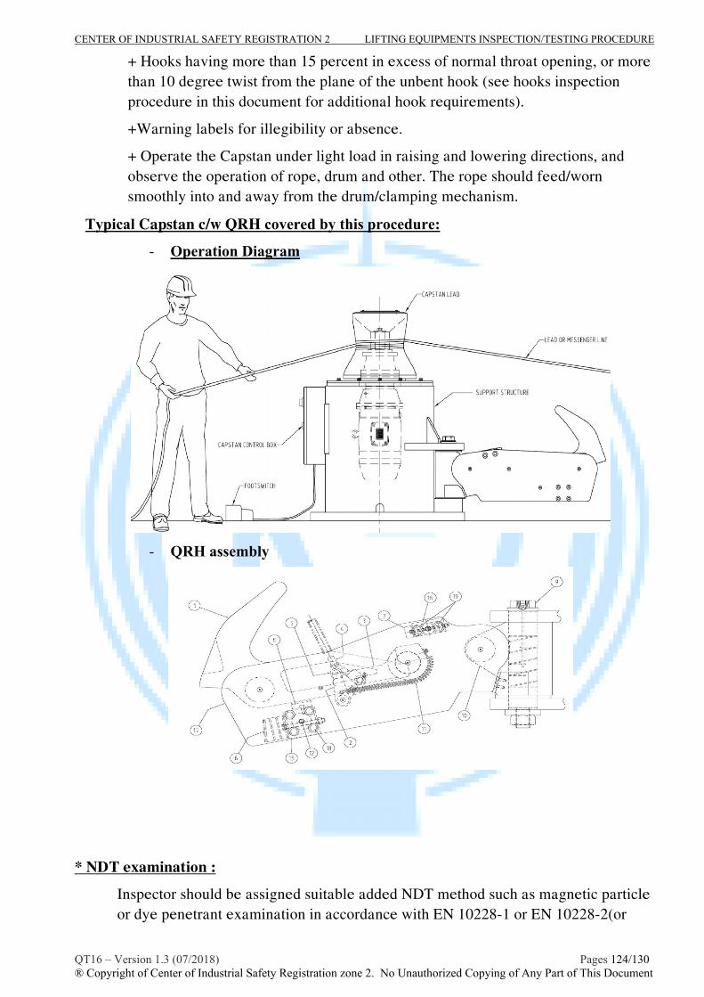
CENTER OF INDUSTRIAL SAFETY REGISTRATION 2 LIFTING EQUIPMENTS INSPECTION/TESTING PROCEDURE
QT16 – Version 1.3 (07/2018) Pages 124/130 ® Copyright of Center of Industrial Safety Registration zone 2. No Unauthorized Copying of Any Part of This Document
+ Hooks having more than 15 percent in excess of normal throat opening, or more than 10 degree twist from the plane of the unbent hook (see hooks inspection procedure in this document for additional hook requirements).
+Warning labels for illegibility or absence.
+ Operate the Capstan under light load in raising and lowering directions, and observe the operation of rope, drum and other. The rope should feed/worn smoothly into and away from the drum/clamping mechanism.
Typical Capstan c/w QRH covered by this procedure:
- Operation Diagram
- QRH assembly
* NDT examination :
Inspector should be assigned suitable added NDT method such as magnetic particle or dye penetrant examination in accordance with EN 10228-1 or EN 10228-2(or

CENTER OF INDUSTRIAL SAFETY REGISTRATION 2 LIFTING EQUIPMENTS INSPECTION/TESTING PROCEDURE
QT16 – Version 1.3 (07/2018) Pages 125/130 ® Copyright of Center of Industrial Safety Registration zone 2. No Unauthorized Copying of Any Part of This Document
ASTM E-709 or ASTM E-165) to inspect for surface intersecting discontinuities of hooks, for his/her added inspection requirement.
III- Testing :
The capstan and hooks should be subjected to test as follow:
III.1- Functioning test:
- Check all functions of the capstan include raising and lowering with light load is 10% of rated load.
- Check all functions of QRH include function of mechanisms, quick release function in manual/ automatic.
III.2- Static load test for support structure and hooks:
- The test load/test force is 125% rated capacity (1,25 WLL).
- The object shall be capable of holding the test load/test force within 10minutes. Observe the test process.
- After this test, the object and it parts should be accepted only if found free from permanent deformations, cracks, or other defects.
If satisfactory, the object to be tested shall be hard stamped in adequate position (or tagged data plate) with test details and a report or certificate will be issued.
IV- Schedule of examination and test:
The Capstan c/w QRH shall be periodically visual inspected, MT/PT examined and functional tested with interval not exceeding 12 months.
Periodic Load test should be carried out in accordance with recommendation of inspector or client requirements at least 05 years.
When the schedule requires a load test, any non-destructive examination and visual inspection shall both be carried out after the load test.
V- Report the result of inspection/testing:
- The inspector shall be completed and report the result of inspection/testing in accordance with the form M16.23.1 and issue the inspection/loadtest certificate in accordance with the form M16.2.2 . - The inspection certificate shall be issued in accordance with the CISR’s procedure No. TT09.

CENTER OF INDUSTRIAL SAFETY REGISTRATION 2 LIFTING EQUIPMENTS INSPECTION/TESTING PROCEDURE
QT16 – Version 1.3 (07/2018) Pages 126/130 ® Copyright of Center of Industrial Safety Registration zone 2. No Unauthorized Copying of Any Part of This Document
PROCEDURE No : QT 16 DNV .24 INSPECTION, TESTING PROCEDURE FOR
RETRACTABLE FALL ARRESTER
A- SCOPE
This procedure provides general guidelines for competent person on performing periodic inspection and load testing services for “Retractable Fall Arrester” to ensure that it is capable of performing it’s intended function and fit for use.
The periodical inspection is aimed to:
verify that the PPE has not been modified; verify the good condition of the PPE; identify possible damages / defects that could require a further control or cause the
discarding of the PPE;
The guidance and recommendation will meet the requirements of:
- BS EN 360:2002 - Personal protective equipment against falls from a height – Retractable Type fall arrester. - BS EN 364:1992 - Personal protective equipment against falls from a height – Test methods - BS EN 362:1993 - Personal protective equipment against falls from a height. Connectors
- BS EN 365: 1993 - Personal protective equipment against falls from a height. General requirement for instructions for use and for marking
B- INSPECTION/EXAMINATION/TESTING
I- Technical Requirements prior to inspection:
The inspector, who carried out the inspection/testing, shall be determined clearly the specifications of the object to be inspected, e.g SWL by means of review manufactured documents, last inspection/testing report.
II - Inspection/Examination Procedure
- Inspector shall be carried out visual inspection, records identified information of specifications of the object to be inspected in to checklist as in M16.24.1 form attached in this procedure (refer to it technical document or check on marking for specifications).
- Adequate lighting and other facilities should be provided to carry out the inspection in all aspects of the object to be inspected.
- Marking/Warning: Retractable Fall Arrester shall be marked permanently and legibly on a non removable of the device with at least the following information:
a)Manufacturer or supplier;
c) Fabrication number/model;
d) Year of production;
e) The specific conditions under which a retractable type fall arrester may be used, e.g. vertical, horizontal or inclined;

CENTER OF INDUSTRIAL SAFETY REGISTRATION 2 LIFTING EQUIPMENTS INSPECTION/TESTING PROCEDURE
QT16 – Version 1.3 (07/2018) Pages 127/130 ® Copyright of Center of Industrial Safety Registration zone 2. No Unauthorized Copying of Any Part of This Document
f) Pictogram or other method to indicate the necessity for users to read the instructions for use
- The object to be inspected should be disassembled for cleaning and thorough inspection/examination for all internal parts (If needed).
- Checked for functional and defects as follow groups:
TT Inspection Items Description
1 HARDWARE Swivel; ring; Connector; hook…
2 HOUSING/BODY Parts and assembly of housing
3 LIFE LINE Wire rope; webbing sling; synthetic sling..
4 SHOCK PACK Impact indicator,.
5 LABEL/TAG Warning/Marking
6 FUNCTION Retractable, Brake mechanism.
a. Checking for housing and label/marking:
+ Inspect the unit’s housing for loose or absent fasteners and bent, cracked, distorted, worn, malfunctioning or damaged parts.
+Warning labels for illegibility or absence.
b. Checking for hardware and function(Connector, ring, swivel, hook, brake..):
+ Controls and operating mechanisms, braking/locking system for proper operation.
+ Worn, corroded, cracked, or distorted parts such as pins, bearings, shafts, gears, rollers locking, and clamping devices, connector…
+ Deterioration or damage of end connections and terminations load rope.
+Function of connector gate and lock; operating signal of impact indicator.
+ Any wear exceeding 10% of the original section dimension of the hook or its load pin.
+ Hook-retaining nuts or collars and pins, welds, or riveting used to secure the retaining members. Check that hook latch, if provided, is not missing and that it operates properly
+ Any cracks in hooks.
+ Hooks having more than 15 percent in excess of normal throat opening, or more than 10 degree twist from the plane of the unbent hook (see hooks inspection procedure in this document for additional hook requirements).
+ The braking mechanism can be tested by grasping the lifeline above the load indicator and applying a sharp steady pull downward which will engage the brakes. There should be no slippage of the lifeline while the brakes are engaged. Once tension
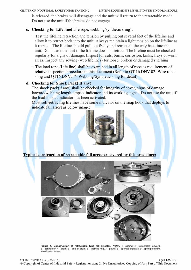
CENTER OF INDUSTRIAL SAFETY REGISTRATION 2 LIFTING EQUIPMENTS INSPECTION/TESTING PROCEDURE
QT16 – Version 1.3 (07/2018) Pages 128/130 ® Copyright of Center of Industrial Safety Registration zone 2. No Unauthorized Copying of Any Part of This Document
is released, the brakes will disengage and the unit will return to the retractable mode. Do not use the unit if the brakes do not engage.
c. Checking for Life line(wire rope, webbing/synthetic sling):
+ Test the lifeline retraction and tension by pulling out several feet of the lifeline and allow it to retract back into the unit. Always maintain a light tension on the lifeline as it retracts. The lifeline should pull out freely and retract all the way back into the unit. Do not use the unit if the lifeline does not retract. The lifeline must be checked regularly for signs of damage. Inspect for cuts, burns, corrosion, kinks, frays or worn areas. Inspect any sewing (web lifelines) for loose, broken or damaged stitching
+ The load rope (Life line) shall be examined in all length of rope as requirement of relative inspection procedure in this document (Refer to QT 16.DNV.02- Wire rope sling and QT16.DNV.17- Webbing/Synthetic sling for detail).
d. Checking for Shock Pack( If any) The shock pack(if any) shall be checked for integrity of cover, signs of damage, lanyard/webbing length, impact indicator and its working signal. Do not use the unit if the load impact indicator has been activated. Most self-retracting lifelines have some indicator on the snap hook that deploys to indicate fall arrest as below image:
Typical construction of retractable fall arrester covered by this procedure:

CENTER OF INDUSTRIAL SAFETY REGISTRATION 2 LIFTING EQUIPMENTS INSPECTION/TESTING PROCEDURE
QT16 – Version 1.3 (07/2018) Pages 129/130 ® Copyright of Center of Industrial Safety Registration zone 2. No Unauthorized Copying of Any Part of This Document
* NDT examination :
Inspector should be assigned suitable added NDT method such as magnetic particle or dye penetrant examination in accordance with EN 10228-1 or EN 10228-2(or ASTM E-709 or ASTM E-165) to inspect for surface intersecting discontinuities of hooks, links… for his/her added inspection requirement.
III- Testing:
The RFA should be subjected to Dynamic Performance test as follow:
Testing in accordance with requirement of BS EN 364:1993 clause 5.7, as follow requirement and procedure:
Test load: Using the cylindrical type steel rigid with mass 100kg, nominal diameter of rigid is 200mm. Maximum accuracy of test load is 1%.
Rigid Anchorage point: The rigid anchorage structure shall be so constructed that its natural frequency. The rigid anchorage point shall be a ring of (20± 1) mm bore and (15 ± 1) mm diameter cross section, or a rod of same diameter cross section.
The force measuring apparatus shall be capable of measuring forces from 1,2 kN to 20 kN with an accuracy of ± 2 %.
Secure the top of the arrester to the rigid structural anchorage point incorporating the force measurement instrument as shown in Figure 9.
Withdraw the retractable lanyard 600 mm from the fall arrester and attach a clip to prevent retraction. Attach the 100 kg mass. Raise the mass so that its eyebolt is horizontally in line with the clip and, at a maximum of 300 mm horizontally from the centre line, hold it by the quick release device.
Let the mass fall and measure the peak arrest force. After the fall and with the mass at rest measure the displacement H. If the arrester includes a fall indicator, confirm that this has operated in accordance with the manufacturer’s information.
After this test, the object to be tested and it parts should be accepted only if found free from permanent deformations, cracks, or other defects.

CENTER OF INDUSTRIAL SAFETY REGISTRATION 2 LIFTING EQUIPMENTS INSPECTION/TESTING PROCEDURE
QT16 – Version 1.3 (07/2018) Pages 130/130 ® Copyright of Center of Industrial Safety Registration zone 2. No Unauthorized Copying of Any Part of This Document
If satisfactory, the RFA shall be tagged with suitable tag name and a report/certificate will be issued.
IV- Schedule of examination and test:
The RFA c/w accessories shall be periodically visual inspected, MT/PT examined, function test with interval not exceeding 12 months.
Periodic Load test should be carried out in accordance with specific recommendation of inspector or client requirements at least 2 years.
When the schedule requires a load test, any non-destructive examination and visual inspection shall both be carried out after the load test.
V- Report the result of inspection/testing:
- The inspector shall be completed and reported the result of inspection/testing in accordance with the form M16.24.1 and issued the inspection/loadtest certificate in accordance with the form M16.3.2. - The inspection certificate shall be issued in accordance with the CISR’s procedure No. TT09.

Form M 16.1.1 - QT 16 Ver. 1.3 – Lifted equipment report Page 1/2
CISR CENTER OF INDUSTRIAL SAFETY
REGISTRATION ZONE 2
6 floor, Citilight tower 45, Vo Thi Sau, Dakao Ward, District 1, HCM City Tel:083.8275301‐064.615653Fax:083.8275300‐064.592665
Website : www.kiemdinh.vn ;
REPORT OF INSPECTION/EXAMINATION/TESTING FOR LIFTED EQUIPMENT (Container, Skid, Skip, Basket, Lifting frame…)
Work order No. :……………………..Date :…………….. Location :
Client/ owner
Name : Address
References Inspection procedure QT 16 – Lifting equipments inspection/testing procedure Codes/Standards
Testing Equipments to be used for examination/testing: See reverse side for detail DETAIL OF INSPECTION/EXAMINATION/TESTING
No. of equipment to be inspected 1 2 3
Type of Equipment Offshore container
MSK 65 Skid of Generator
HTTACHI 750 Lifting frame DEMAG 12K
Max.gross mass (R-rating) 10 t 10 /
Tare mass (T) 2 t N/A 2 t
Payload(P);Safe working load(SWL) P = 8 t N/A SWL =8 t
External dimensions (LxWxH) 6x1,5x1,2m 3x1,5x1,2m 3x1,5x0,4m
Manufacturer PTSC OS PTSC OS Demag
Date of manufacturer 2009 2009 1998
Serial/ID No. C2314 C 1114 K 1111
Diameter of hole of pad-eyes Ø 32 Ø 20 Ø 32
Max angle to vertical of sling legs 450 450 450
Secured Lifting set (*) N/A N/A N/A
Type of inspection/examination Visual NDT Visual NDT Visual NDT +Marking s s s +Primary structure s s s +Secondary structure s N/A N/A +Welds s s s s s s +Lifting point (Padeye, pad ear) s s s s s s +Door closures N/A N/A N/A +Floor s N/A N/A +Forklift pocket s s N/A
All point load test with test load (2,5R) See reverse side for detail Two point load test (1,5R) See reverse side for detail
Assessments : □ Accept □ Repair
□ Reject
□ Accept □ Repair
□ Reject
□ Accept □ Repair
□ Reject Next recommended inspection We certify that the above particulars are correct, and that the examination and test was carried out by the competent person in the manner set forth on the applied procedure/standards.
Inspector/Examiner:…………………….. Witness:………………………………….. Signature :…………………………………. Signature :…………………….…………. Remarks: Use reverside for more description, recommendation,interpretation.. if need ; (*) Use reverside or appropriate form in the procedure QT16 for detail inspection if need.;N/A : Not applicable ; S : it is sastisfactory ; R : it isn’t sastisfactory

Form M 16.1.1 - QT 16 Ver. 1.3 – Lifted equipment report Page 2/2
1- Defects/imperfects to be found in the visual inspection/MT-PT Examination/Load test ………………………………………………………………………………………………………………………………………………………………………………………………………………………………………………………………………………………………………………………………………………………………………………………………………………………………………………………………………………………………………… ………………………………………………………………………………………………………………………… ……………………………………………………………………………………………………………………… ………………………………………………………………………………………………………………………… ……………………………………………………………………………………………………………………… ………………………………………………………………………………………………………………………… ………………………………………………………………………………………………………………………… ……………………………………………………………………………………………………………………………………………………………………………………………………………………………………………………………………………………………………………………………………………………………………………………………………………………………………………………………………………………………………… ………………………………………………………………………………………………………………………… ……………………………………………………………………………………………………………………… ………………………………………………………………………………………………………………………… 2- Load Test Record
No. of tested object
(1) (2) (3) (4)
Test Date
Test equipment Serial/ID Number Description of
Equipment Calibrated cert. No Valid until
Type of test
Applied Standard
Required Test Load/Test Force
Real Test Load/Force
Holding time (min)
Tested Result □ Pass
□ Reject
□ Pass
□ Reject
□ Pass
□ Reject
□ Pass
□ Reject Note: if the test not pass, carefully record all of defects such as broken, deformation, crack… in Item 1.
……………………………………………………………………………………………………………………… ………………………………………………………………………………………………………………………… NDT ( MT PT) was carried out by technician:…………………………………………………………. ASNT level 2, No……………………….. For ........................................................................................ ………………………………………………………………………………………………………………………… ………………………………………………………………………………………………………………………… ………………………………………………………………………… before load test after load test NDT report No: …………………………… firm issued…………………………………………………………

Form M 16.2.1 - QT 16 Ver. 1.3 – Wire rope sling report Page 1/2
CISR CENTER OF INDUSTRIAL SAFETY
REGISTRATION ZONE 2
6 floor, Citilight tower 45, Vo Thi Sau, Dakao Ward, District 1, HCM City Tel:083.8275301‐064.615653Fax:083.8275300‐064.592665
Website : www.kiemdinh.vn ;
REPORT OF INSPECTION/EXAMINATION/TESTING FOR WIRE ROPE LIFTING SLING
Work order No. :……………………..Date :…………….. Location :
Client/ owner
Name : Address
References Inspection procedure QT 16 – Lifting equipments inspection/testing procedure Codes/Standards
Testing Equipments to be used for examination/testing: See reverse side for detail DETAIL OF INSPECTION/EXAMINATION/TESTING
No. of equipment to be inspected 1 2 3
Type/Mode of Sling 4 legs wire rope
sling
Safe working load (SWL) 05t
Max angle to vertical of sling legs 450
Manufacturer Valin Ltd.
Date of manufacturer 2000
Serial/ID No. KT-1111
Contruction of rope, Length and Diameter of legs
6x36 + 1 IWRC 3m x Ø 20
Contruction of rope, Length and Diameter of forerunner
6x36 + 1 IWRC 1m x Ø 40
Secured lifting gear (*)
Type of inspection/examination Visual NDT Visual NDT Visual NDT +Marking and Identification s +Master link s s +Intermediate link, Leg link s s +Fore runner rope and rope eyes s +Leg rope and rope eyes s +Dimensions of matched legs s
Load test with all legs (2 SWL) See reverse side for detail Load test with individual leg See reverse side for detail
Assessments : □ Accept □ Repair
□ Reject
□ Accept □ Repair
□ Reject
□ Accept □ Repair
□ Reject Next recommended inspection We certify that the above particulars are correct, and that the examination and test was carried out by
the competent person in the manner set forth on the applied procedure/standards.
Inspector/Examiner:…………………….. Witness:………………………………….. Signature :…………………………………. Signature :…………………….…………. Remarks: Use reverside for more description, recommendation,interpretation.. if need ; (*) Use reverside or appropriate form in the procedure QT16 for detail inspection if need.;N/A : Not applicable ; S : it is sastisfactory ; R : it isn’t sastisfactory

Form M 16.2.1 - QT 16 Ver. 1.3 – Wire rope sling report Page 2/2
1- Defects/imperfects to be found in the visual inspection/MT-PT Examination/Load test ………………………………………………………………………………………………………………………………………………………………………………………………………………………………………………………………………………………………………………………………………………………………………………………………………………………………………………………………………………………………………… ………………………………………………………………………………………………………………………… ……………………………………………………………………………………………………………………… ………………………………………………………………………………………………………………………… ……………………………………………………………………………………………………………………… ………………………………………………………………………………………………………………………… ………………………………………………………………………………………………………………………… ……………………………………………………………………………………………………………………………………………………………………………………………………………………………………………………………………………………………………………………………………………………………………………………………………………………………………………………………………………………………………… ………………………………………………………………………………………………………………………… ……………………………………………………………………………………………………………………… ………………………………………………………………………………………………………………………… 2- Load Test Record
No. of tested object
(1) (2) (3) (4)
Test Date
Test equipment Serial/ID Number Description of
Equipment Calibrated cert. No Valid until
Type of test
Applied Standard
Required Test Load/Test Force
Real Test Load/Force
Holding time (min)
Tested Result □ Pass
□ Reject
□ Pass
□ Reject
□ Pass
□ Reject
□ Pass
□ Reject Note: if the test not pass, carefully record all of defects such as broken, deformation, crack… in Item 1.
……………………………………………………………………………………………………………………… ………………………………………………………………………………………………………………………… NDT ( MT PT) was carried out by technician:…………………………………………………………. ASNT level 2, No……………………….. For ........................................................................................ ………………………………………………………………………………………………………………………… ………………………………………………………………………………………………………………………… ………………………………………………………………………… before load test after load test NDT report No: …………………………… firm issued…………………………………………………………
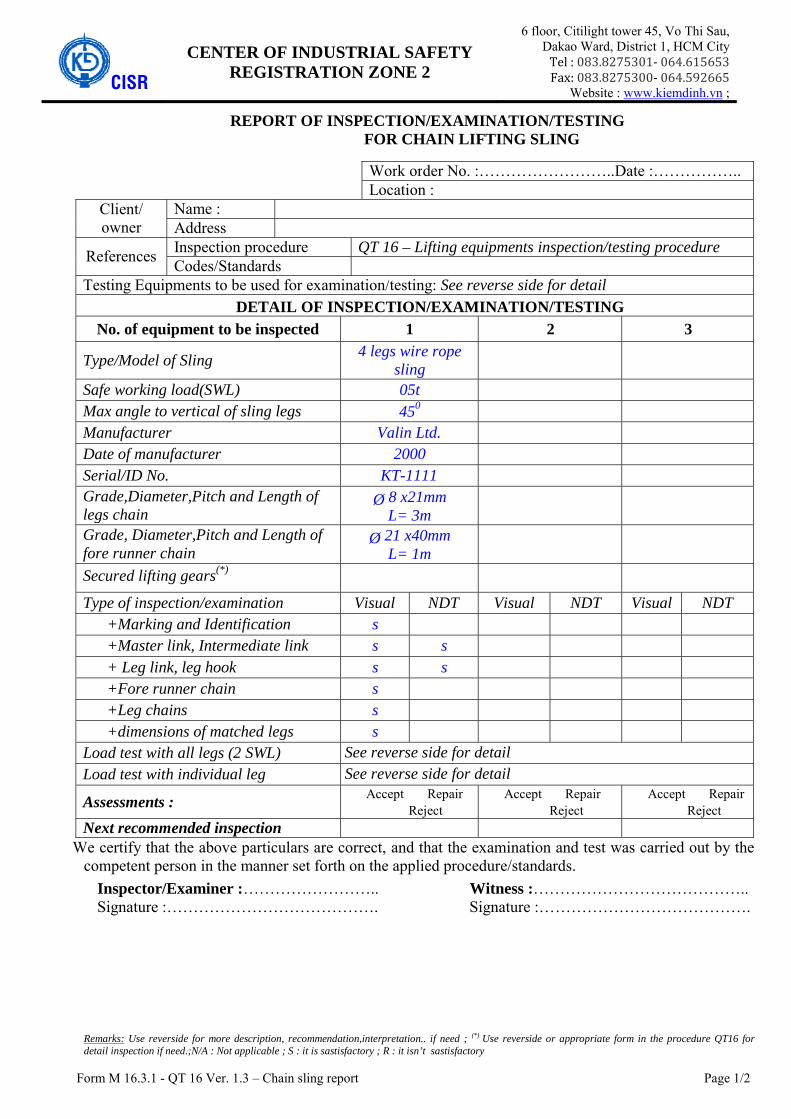
Form M 16.3.1 - QT 16 Ver. 1.3 – Chain sling report Page 1/2
CISR CENTER OF INDUSTRIAL SAFETY
REGISTRATION ZONE 2
6 floor, Citilight tower 45, Vo Thi Sau, Dakao Ward, District 1, HCM City Tel:083.8275301‐064.615653Fax:083.8275300‐064.592665
Website : www.kiemdinh.vn ;
REPORT OF INSPECTION/EXAMINATION/TESTING FOR CHAIN LIFTING SLING
Work order No. :……………………..Date :……………..
Location :Client/ owner
Name : Address
References Inspection procedure QT 16 – Lifting equipments inspection/testing procedure Codes/Standards
Testing Equipments to be used for examination/testing: See reverse side for detail DETAIL OF INSPECTION/EXAMINATION/TESTING
No. of equipment to be inspected 1 2 3
Type/Model of Sling 4 legs wire rope
sling
Safe working load(SWL) 05t
Max angle to vertical of sling legs 450
Manufacturer Valin Ltd.
Date of manufacturer 2000 Serial/ID No. KT-1111 Grade,Diameter,Pitch and Length of legs chain
Ø 8 x21mm L= 3m
Grade, Diameter,Pitch and Length of fore runner chain
Ø 21 x40mm L= 1m
Secured lifting gears(*)
Type of inspection/examination Visual NDT Visual NDT Visual NDT +Marking and Identification s +Master link, Intermediate link s s
+ Leg link, leg hook s s
+Fore runner chain s
+Leg chains s
+dimensions of matched legs s
Load test with all legs (2 SWL) See reverse side for detail Load test with individual leg See reverse side for detail
Assessments : � Accept � Repair
� Reject� Accept � Repair
� Reject � Accept � Repair
� RejectNext recommended inspection
We certify that the above particulars are correct, and that the examination and test was carried out by the competent person in the manner set forth on the applied procedure/standards.
Inspector/Examiner :…………………….. Witness :………………………………….. Signature :…………………………………. Signature :………………………………….
Remarks: Use reverside for more description, recommendation,interpretation.. if need ; (*) Use reverside or appropriate form in the procedure QT16 for detail inspection if need.;N/A : Not applicable ; S : it is sastisfactory ; R : it isn’t sastisfactory

Form M 16.3.1 - QT 16 Ver. 1.3 – Chain sling report Page 2/2
1- Defects/imperfects to be found in the visual inspection/MT-PT Examination/Load test ……………………………………………………………………………………………………………………… ……………………………………………………………………………………………………………………… ……………………………………………………………………………………………………………………… ……………………………………………………………………………………………………………………… ……………………………………………………………………………………………………………………… ……………………………………………………………………………………………………………………… ……………………………………………………………………………………………………………………… ……………………………………………………………………………………………………………………… ……………………………………………………………………………………………………………………… ……………………………………………………………………………………………………………………… ……………………………………………………………………………………………………………………… ……………………………………………………………………………………………………………………… ……………………………………………………………………………………………………………………… ……………………………………………………………………………………………………………………… ……………………………………………………………………………………………………………………… ……………………………………………………………………………………………………………………… ……………………………………………………………………………………………………………………… ………………………………………………………………………………………………………………………
2- Load Test Record No. of tested
object (1) (2) (3) (4)
Test Date
Test equipment Serial/ID Number Description of
Equipment Calibrated cert. No Valid until
Type of test
Applied Standard
Required Test Load/Test Force
Real Test Load/Force
Holding time (min)
Tested Result □ Pass
□ Reject
□ Pass
□ Reject
□ Pass
□ Reject
□ Pass
□ Reject Note: if the test not pass, carefully record all of defects such as broken, deformation, crack… in Item 1. ……………………………………………………………………………………………………………………… ……………………………………………………………………………………………………………………… NDT(� MT �PT) was carried out by technician :……………………………………........…………. ASNT level 2, No……………………….. For .................................................................................... ……………………………………………………………………………………………………………………… ……………………………………………………………………………………………………………………… …………………………………………………………………………� before load test � after load test
NDT report No: …………………………… firm issued…………………………………………………………

Form M 16.4.1- QT 16 Ver. 1.3– shackle report Page 1/2
CISR
CENTER OF INDUSTRIAL SAFETY
REGISTRATION ZONE 2
6 floor, Citilight tower,45 Vo Thi Sau Dakao Ward, District 1, HCM City
Tel : 083.8275301‐064.615653 Fax: 083.8275300‐064.592665 Website : www.kiemdinh.vn ;
REPORT OF INSPECTION/EXAMINATION/TESTING FOR SHACKLES
Work order No. :……………………..Date :……………..
Location :Client/ owner
Name : Address
References Inspection procedure QT 16 – Lifting equipments inspection/testing procedure Codes/Standards
Testing Equipments to be used for examination/testing: See reverse side for detail DETAIL OF INSPECTION/EXAMINATION/TESTING
No. of equipment to be inspected 1 2 3 4
Type/Model of Shackle CROSBY S2101
Working load limit (WLL) 05t
Grade, material 6
Manufacturer CROSBY
Date of manufacturer 2000
Body Serial/ID No. KT-1111
Shackle body, Diameter of shackle hole.
Bow, forged steel
Ø 31mm
Pin, Diameter of Pin Bolt type pin
Ø 30mm
Type of inspection/examination Visual NDT Visual NDT Visual NDT Visual NDT
+Marking and Identification s
+Shackle body s s
+Shackle hole (thread if any) s
+Opening up of shackle s +Pin s s
+Thread of pin, bolt s
+Other :
Proof Load test (test load = 2x WLL) See reverse side for detail Assessments :
� Accept � Repair � Reject
� Accept � Repair � Reject
� Accept � Repair � Reject
� Accept � Repair � Reject
Next recommended inspection We certify that the above particulars are correct, and that the examination and test was carried out by the competent person in the manner set forth on the applied procedure/standards.
Inspector/Examiner :…………………….. Witness :………………………………….. Signature :…………………………………. Signature :………………………………….
Remarks: Use reverside for more description, recommendation,interpretation.. if need ; (*) Use reverside or appropriate form in the procedure QT16 for detail inspection if need.;N/A : Not applicable ; S : it is sastisfactory ; R : it isn’t sastisfactory
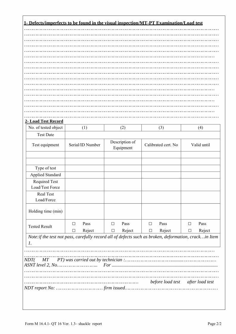
Form M 16.4.1- QT 16 Ver. 1.3– shackle report Page 2/2
1- Defects/imperfects to be found in the visual inspection/MT-PT Examination/Load test ………………………………………………………………………………………………………………………… ………………………………………………………………………………………………………………………… ………………………………………………………………………………………………………………………… ………………………………………………………………………………………………………………………… ………………………………………………………………………………………………………………………… ……………………………………………………………………………………………………………………… ………………………………………………………………………………………………………………………… ………………………………………………………………………………………………………………………… ………………………………………………………………………………………………………………………… ………………………………………………………………………………………………………………………… ………………………………………………………………………………………………………………………… ……………………………………………………………………………………………………………………… ………………………………………………………………………………………………………………………… ……………………………………………………………………………………………………………………… ………………………………………………………………………………………………………………………… ……………………………………………………………………………………………………………………… …………………………………………………………………………………………………………………………
2- Load Test Record
No. of tested object (1) (2) (3) (4)
Test Date
Test equipment Serial/ID Number Description of
Equipment Calibrated cert. No Valid until
Type of test
Applied Standard
Required Test Load/Test Force
Real Test Load/Force
Holding time (min)
Tested Result □ Pass
□ Reject
□ Pass
□ Reject
□ Pass
□ Reject
□ Pass
□ Reject
Note:if the test not pass, carefully record all of defects such as broken, deformation, crack…in Item 1.
……………………………………………………………………………………………………………………… ………………………………………………………………………………………………………………………… NDT(� MT �PT) was carried out by technician :…………………………….........…………………… ASNT level 2, No……………………….. For ......................................................................................... ………………………………………………………………………………………………………………………… ………………………………………………………………………………………………………………………… ……………………………………………………………………… � before load test � after load test NDT report No: …………………………… firm issued…………………………………………………………

Form M 16.5.1- QT 16 Ver. 1.3- hook report Page 1/2
CISR
CENTER OF INDUSTRIAL SAFETY
REGISTRATION ZONE 2
6 floor, Citilight tower,45 Vo Thi Sau Dakao Ward, District 1, HCM City
Tel : 083.8275301‐064.615653 Fax: 083.8275300‐064.592665
Website : www.kiemdinh.vn ;
REPORT OF INSPECTION/EXAMINATION/TESTING FOR LIFTING HOOKS
Work order No. :……………………..Date :……………..
Location :Client/ owner
Name : Address
References Inspection procedure QT 16 – Lifting equipments inspection/testing procedure Codes/Standards
Testing Equipments to be used for examination/testing: See reverse side for detail DETAIL OF INSPECTION/EXAMINATION/TESTING
No. of equipment to be inspected 1 2 3 4
Type/Model of HOOKS Swivel hook S2101
Working load limit (WLL) 05t
Material grade N/A
Manufacturer CROSBY
Date of manufacturer 2000
Serial/ID No. KT-1111 Weight of hooks 15kg
Pin, Diameter of Pin N/A
Diameter of Eye of hook N/A
Type of inspection/examination Visual NDT Visual NDT Visual NDT Visual NDT
+Marking and Identification s
+hook body s s +throat opening of hook s
+hole of eye hooks n/a
+Pins n/a
+thread of pin, bolt n/a
+ Latch s
+ Swivel s s Proof Load test (test load = 2x WLL) See reverse side for detail
Assessments :
� Accept � Repair � Reject
� Accept � Repair � Reject
� Accept � Repair � Reject
� Accept � Repair � Reject
Next recommended inspection We certify that the above particulars are correct, and that the examination and test was carried out by the competent person in the manner set forth on the applied procedure/standards.
Inspector/Examiner :…………………….. Witness :………………………………….. Signature :…………………………………. Signature :………………………………….
Remarks: Use reverside for more description, recommendation,interpretation.. if need ; (*) Use reverside or appropriate form in the procedure QT16 for detail inspection if need.;N/A : Not applicable ; S : it is sastisfactory ; R : it isn’t sastisfactory

Form M 16.5.1- QT 16 Ver. 1.3- hook report Page 2/2
1- Defects/imperfects to be found in the visual inspection/MT-PT Examination/Load test ………………………………………………………………………………………………………………………… ………………………………………………………………………………………………………………………… ……………………………………………………………………………………………………………………… ………………………………………………………………………………………………………………………… ……………………………………………………………………………………………………………………… ………………………………………………………………………………………………………………………… ………………………………………………………………………………………………………………………… ………………………………………………………………………………………………………………………… ……………………………………………………………………………………………………………………… ………………………………………………………………………………………………………………………… ……………………………………………………………………………………………………………………… ………………………………………………………………………………………………………………………… ………………………………………………………………………………………………………………………… ……………………………………………………………………………………………………………………… ………………………………………………………………………………………………………………………… ………………………………………………………………………………………………………………………… 2- Load Test Record
No. of tested object
(1) (2) (3) (4)
Test Date
Test equipment Serial/ID Number Description of
Equipment Calibrated cert.
No Valid until
Type of test
Applied Standard
Required Test Load/Test Force
Real Test Load/Force
Holding time (min)
Tested Result □ Pass □ Reject
□ Pass □ Reject
□ Pass □ Reject
□ Pass □ Reject
Note: if the test not pass, carefully record all of defects such as broken, deformation, crack…in Item 1.
……………………………………………………………………………………………………………………… ………………………………………………………………………………………………………………………… NDT(� MT �PT) was carried out by technician :…………………………………………………………. ASNT level 2, No……………………….. For ......................................................................................... ………………………………………………………………………………………………………………………… ………………………………………………………………………………………………………………………… ……………………………………………………………………… � before load test � after load test
NDT report No: …………………………… firm issued…………………………………………………………

Form M 16.6.1- QT 16 Ver. 1.3 - link report Page 1/2
CISR
CENTER OF INDUSTRIAL SAFETY
REGISTRATION ZONE 2
6 floor, Citilight tower, 45 Vo Thi Sau Dakao Ward, District 1, HCM City
Tel : 083.8275301‐064.615653 Fax: 083.8275300‐064.592665 Website : www.kiemdinh.vn ;
REPORT OF INSPECTION/EXAMINATION/TESTING FOR LINK, MASTER LINK, RING
Work order No. :……………………..Date :……………..
Location :Client/ owner
Name : Address
References Inspection procedure QT 16 – Lifting equipments inspection/testing procedure Codes/Standards
Testing Equipments to be used for examination/testing: See reverse side for detail DETAIL OF INSPECTION/EXAMINATION/TESTING
No. of equipment to be inspected 1 2 3 4
Type/Model of Links Master link assembly
Working load limit (WLL) 05t
Material grade 8
Manufacturer CROSBY
Date of manufacturer 2000
Serial/ID No. KT-1111 Dimension of master links 15kg
Dimension of intermediate links N/A
Type of inspection/examination Visual NDT Visual NDT Visual NDT Visual NDT
-Marking and Identification s
-Master link s s
+Worn, corrosion, gouge.. s +Distortion, deformation.. s
+Crack; heat-chemical damage s
- Intermediate links n/a
+Worn, corrosion, gouge..
+Distortion, deformation..
+Crack; heat-chemical damage Proof load test (test load = 2WLL) See reverse side for detail
Assessments :
� Accept � Repair � Reject
� Accept � Repair � Reject
� Accept � Repair � Reject
� Accept � Repair � Reject
Next recommended inspection We certify that the above particulars are correct, and that the examination and test was carried out by the competent person in the manner set forth on the applied procedure/standards.
Inspector/Examiner :…………………….. Witness :……………………………… Signature :…………………………………. Signature :………………………………
Remarks: Use reverside for more description, recommendation,interpretation.. if need ; (*) Use reverside or appropriate form in the procedure QT16 for detail inspection if need.;N/A : Not applicable ; S : it is sastisfactory ; R : it isn’t sastisfactory

Form M 16.6.1- QT 16 Ver. 1.3 - link report Page 2/2
1- Defects/imperfects to be found in the visual inspection/MT-PT Examination/Load test ………………………………………………………………………………………………………………………… ………………………………………………………………………………………………………………………… ………………………………………………………………………………………………………………………… ………………………………………………………………………………………………………………………… ………………………………………………………………………………………………………………………… ……………………………………………………………………………………………………………………… ………………………………………………………………………………………………………………………… ……………………………………………………………………………………………………………………… ………………………………………………………………………………………………………………………… ………………………………………………………………………………………………………………………… ………………………………………………………………………………………………………………………… ………………………………………………………………………………………………………………………… ………………………………………………………………………………………………………………………… ………………………………………………………………………………………………………………………… ………………………………………………………………………………………………………………………… 2- Load Test Record
No. of tested object
(1) (2) (3) (4)
Test Date
Test equipment Serial/ID Number Description of
Equipment Calibrated cert.
No Valid until
Type of test
Applied Standard
Required Test Load/Test Force
Real Test Load/Force
Holding time (min)
Tested Result □ Pass □ Reject
□ Pass □ Reject
□ Pass □ Reject
□ Pass □ Reject
Note: if the test not pass, carefully record all of defects such as broken, deformation, crack…in Item 1.
……………………………………………………………………………………………………………………… ………………………………………………………………………………………………………………………… NDT(� MT �PT) was carried out by technician :…………………………………………………… ASNT level 2, No……………………….. For ......................................................................................... ………………………………………………………………………………………………………………………… ………………………………………………………………………………………………………………………… …………………………………………………………………… � before load test � after load test
NDT report No: …………………………… firm issued…………………………………………………………

Form M 16.7.1- QT 16 Ver. 1.3- clamp report Page 1/2
CISR
CENTER OF INDUSTRIAL SAFETY
REGISTRATION ZONE 2
6 floor, Citilight tower, 45 Vo Thi Sau, Dakao Ward, District 1, HCM City
Tel : 083.8275301‐064.615653 Fax: 083.8275300‐064.592665 Website : www.kiemdinh.vn ;
REPORT OF INSPECTION/EXAMINATION/TESTING FOR PLATE/BEAM CLAMP
Work order No. :……………………..Date :……………..
Location :Client/ owner
Name : Address
References Inspection procedure QT 16 – Lifting equipments inspection/testing procedure Codes/Standards
Equipments to be used for examination/testing: See reverse side for detailDETAIL OF INSPECTION/EXAMINATION/TESTING
No. of equipment to be inspected 1 2 3
4
Type/Model of Clamp Beam clamp Working load limit (WLL) 05t
Manufacturer CROSBY
Date of manufacturer 2000 Serial/ID No. KT-1111 Maximum thickness of plate or sizes ofbeam can be clamped.
I 200
Secured lifting gears(*) N/A
Type, result of inspection/examination Visual NDT Visual NDT Visual NDT Visual NDT
+Marking and Identification s
+Body s s +Pin, thread of pin s s
+Eye, rings s s
+Bearing surface s
+Locking lever & spring n/a
+Locking device (Clamping bolt..) s
+ general operation s +Paint, maintenance s
Proof load test (test load = ………….) See reverse side for detail Assessments :
� Accept � Repair � Reject
� Accept � Repair � Reject
� Accept � Repair � Reject
� Accept � Repair � Reject
Next Recommended inspection
Inspector/Examiner :…………………….. Witness :………………………………….. Signature :…………………………………. Signature :………………………………….
Remarks: Use reverside for more description, recommendation,interpretation.. if need ; (*) Use reverside or appropriate form in the procedure QT16 for detail inspection if need.;N/A : Not applicable ; S : it is sastisfactory ; R : it isn’t sastisfactory

Form M 16.7.1- QT 16 Ver. 1.3- clamp report Page 2/2
1- Defects/imperfects to be found in the visual inspection/MT-PT Examination/Load test ………………………………………………………………………………………………………………………… ………………………………………………………………………………………………………………………… ………………………………………………………………………………………………………………………… ………………………………………………………………………………………………………………………… ………………………………………………………………………………………………………………………… ……………………………………………………………………………………………………………………… ………………………………………………………………………………………………………………………… ……………………………………………………………………………………………………………………… ………………………………………………………………………………………………………………………… ………………………………………………………………………………………………………………………… ………………………………………………………………………………………………………………………… ………………………………………………………………………………………………………………………… ………………………………………………………………………………………………………………………… ……………………………………………………………………………………………………………………… ………………………………………………………………………………………………………………………… ……………………………………………………………………………………………………………………… ………………………………………………………………………………………………………………………… 2- Load Test Record
No. of tested object
(1) (2) (3) (4)
Test Date
Test equipment Serial/ID Number Description of
Equipment Calibrated cert.
No Valid until
Type of test
Applied Standard
Required Test Load/Test Force
Real Test Load/Force
Holding time (min)
Tested Result □ Pass □ Reject
□ Pass □ Reject
□ Pass □ Reject
□ Pass □ Reject
Note: if the test not pass, carefully record all of defects such as broken, deformation, crack… in Item 1.
……………………………………………………………………………………………………………………… ………………………………………………………………………………………………………………………… NDT(� MT �PT) was carried out by technician :……………… ………………………………………. ASNT level 2, No……………………….. For ......................................................................................... ………………………………………………………………………………………………………………………… ………………………………………………………………………………………………………………………… ………………………………………………………………… � before load test � after load test NDT report No: …………………………… firm issued…………………………………………………………

Form M 16.8.1- QT 16 Ver. 1.3- hammer lock report Page 1/2
CISR
CENTER OF INDUSTRIAL SAFETY
REGISTRATION ZONE 2
6 floor, Citilight tower, 45 Vo Thi Sau Dakao Ward, District 1, HCM City
Tel : 083.8275301‐064.615653 Fax: 083.8275300‐064.592665
Website : www.kiemdinh.vn ;
REPORT OF INSPECTION/EXAMINATION/TESTING FOR HAMMER LOCKS
Work order No. :……………………..Date :……………..
Location :Client/ owner
Name : Address
References Inspection procedure QT 16 – Lifting equipments inspection/testing procedure Codes/Standards
Equipments to be used for examination/testing: See reverse side for detailDETAIL OF INSPECTION/EXAMINATION/TESTING
No. of equipment to be inspected 1 2 3
4
Type of hammer lock Coupling Link G
Model of hammer lock G-10-8
Working load limit (WLL) 05t
Manufacturer CROSBY
Date of manufacturer 2000 Serial/ID No. KT-1111
Matched chain size 10mm
Secured lifting gears(*) N/A
Type, result of inspection/examination Visual NDT Visual NDT Visual NDT Visual NDT
+Marking and Identification s
+Body(worn, gouge, cracks..) s s +Pin, thread of pin, nuts s s
+welds on body s s
+Bearing surface s
+ Operation
+ Other
Proof load test (test load = ………….) See reverse side for detail Assessments :
� Accept � Repair � Reject
� Accept � Repair � Reject
� Accept � Repair � Reject
� Accept � Repair � Reject
Next Recommended inspection
Inspector/Examiner :…………………….. Witness :………………………………….. Signature :…………………………………. Signature :………………………………….
Remarks: Use reverside for more description, recommendation,interpretation.. if need ; (*) Use reverside or appropriate form in the procedure QT16 for detail
inspection if need.;N/A : Not applicable ; S : it is sastisfactory ; R : it isn’t sastisfactory
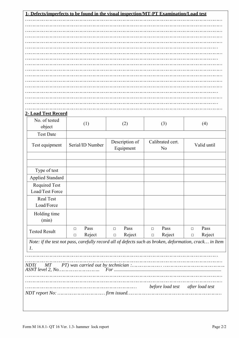
Form M 16.8.1- QT 16 Ver. 1.3- hammer lock report Page 2/2
1- Defects/imperfects to be found in the visual inspection/MT-PT Examination/Load test ………………………………………………………………………………………………………………………… ………………………………………………………………………………………………………………………… ………………………………………………………………………………………………………………………… ………………………………………………………………………………………………………………………… ………………………………………………………………………………………………………………………… ……………………………………………………………………………………………………………………… ………………………………………………………………………………………………………………………… ……………………………………………………………………………………………………………………… ………………………………………………………………………………………………………………………… ………………………………………………………………………………………………………………………… ………………………………………………………………………………………………………………………… ………………………………………………………………………………………………………………………… ………………………………………………………………………………………………………………………… ……………………………………………………………………………………………………………………… ………………………………………………………………………………………………………………………… ……………………………………………………………………………………………………………………… ………………………………………………………………………………………………………………………… 2- Load Test Record
No. of tested object
(1) (2) (3) (4)
Test Date
Test equipment Serial/ID Number Description of
Equipment Calibrated cert.
No Valid until
Type of test
Applied Standard
Required Test Load/Test Force
Real Test Load/Force
Holding time (min)
Tested Result □ Pass □ Reject
□ Pass □ Reject
□ Pass □ Reject
□ Pass □ Reject
Note: if the test not pass, carefully record all of defects such as broken, deformation, crack… in Item 1.
……………………………………………………………………………………………………………………… ………………………………………………………………………………………………………………………… NDT(� MT �PT) was carried out by technician :………………… ……………………………………. ASNT level 2, No……………………….. For ......................................................................................... ………………………………………………………………………………………………………………………… ………………………………………………………………………………………………………………………… …………………………………………………………………… � before load test � after load test NDT report No: …………………………… firm issued…………………………………………………………

Form M 16.9.1 - QT 16 Ver. 1.3- Swivel ring/bolt report Page 1/2
CISR
CENTER OF INDUSTRIAL SAFETY
REGISTRATION ZONE 2
6 floor, Citilight tower, 45 Vo Thi Sau Dakao Ward, District 1, HCM City
Tel : 083.8275301‐064.615653 Fax: 083.8275300‐064.592665
Website : www.kiemdinh.vn ;
REPORT OF INSPECTION/EXAMINATION/TESTING FOR SWIVEL HOIST RING/SWIVEL EYE BOLT
Work order No. :……………………..Date :……………..
Location :Client/ owner
Name : Address
References Inspection procedure QT 16 – Lifting equipments inspection/testing procedure Codes/Standards
Equipments to be used for examination/testing: See reverse side for detailDETAIL OF INSPECTION/EXAMINATION/TESTING
No. of equipment to be inspected 1 2 3
4
Type equipment SWIVEL EYE BOLT
Model G-10-8
Working load limit (WLL) 05t
Manufacturer CROSBY
Date of manufacturer 2000 Serial/ID No. KT-1111
Secured lifting gears(*) N/A
Type, result of inspection/examination Visual NDT Visual NDT Visual NDT Visual NDT
+Marking and Identification s
+Body ring(worn, gouge, cracks..) s s
+Bearing surface s s +shank bolt, thread s s
+ Eye of bolt
+Rotation s
+ Other
Proof load test (test load = ………….) See reverse side for detail Assessments :
� Accept � Repair � Reject
� Accept � Repair � Reject
� Accept � Repair � Reject
� Accept � Repair � Reject
Next Recommended inspection
Inspector/Examiner :…………………….. Witness :………………………………….. Signature :…………………………………. Signature :………………………………….
Remarks: Use reverside for more description, recommendation,interpretation.. if need ; (*) Use reverside or appropriate form in the procedure QT16 for detail inspection if need.;N/A : Not applicable ; S : it is sastisfactory ; R : it isn’t sastisfactory

Form M 16.9.1 - QT 16 Ver. 1.3- Swivel ring/bolt report Page 2/2
1- Defects/imperfects to be found in the visual inspection/MT-PT Examination/Load test ………………………………………………………………………………………………………………………… ………………………………………………………………………………………………………………………… ………………………………………………………………………………………………………………………… ………………………………………………………………………………………………………………………… ………………………………………………………………………………………………………………………… ………………………………………………………………………………………………………………………… ………………………………………………………………………………………………………………………… ………………………………………………………………………………………………………………………… …………………………………………………………………………………………………………………………………………………………………………………………………………………………………………………… ………………………………………………………………………………………………………………………… ………………………………………………………………………………………………………………………… ……………………………………………………………………………………………………………………… ………………………………………………………………………………………………………………………… ……………………………………………………………………………………………………………………… ………………………………………………………………………………………………………………………… 2- Load Test Record
No. of tested object
(1) (2) (3) (4)
Test Date
Test equipment Serial/ID Number Description of
Equipment Calibrated cert.
No Valid until
Type of test
Applied Standard
Required Test Load/Test Force
Real Test Load/Force
Holding time (min)
Tested Result □ Pass □ Reject
□ Pass □ Reject
□ Pass □ Reject
□ Pass □ Reject
Note: if the test not pass, carefully record all of defects such as broken, deformation, crack… in Item 1.
………………………………………………………………………………………………………………………… ……………………………………………………………………………………………………………………… ………………………………………………………………………………………………………………………… NDT(� MT �PT) was carried out by technician :…………………… …………………………………. ASNT level 2, No……………………….. For ......................................................................................... ………………………………………………………………………………………………………………………… ………………………………………………………………………………………………………………………… …………………………………………………………………… � before load test � after load test NDT report No: …………………………… firm issued…………………………………………………………

Form M 16.10.1- QT 16 Ver. 1.3- eye bolt/eye nut report Page 1/2
CISR
CENTER OF INDUSTRIAL SAFETY
REGISTRATION ZONE 2
6 floor, Citilight tower, 45 Vo Thi Sau Dakao Ward, District 1, HCM City
Tel : 083.8275301‐064.615653 Fax: 083.8275300‐064.592665 Website : www.kiemdinh.vn ;
REPORT OF INSPECTION/EXAMINATION/TESTING FOR EYE BOLTS/EYE NUTS
Work order No. :……………………..Date :……………..
Location :Client/ owner
Name : Address
References Inspection procedure QT 16 – Lifting equipments inspection/testing procedure Codes/Standards
Equipments to be used for examination/testing: See reverse side for detailDETAIL OF INSPECTION/EXAMINATION/TESTING
No. of equipment to be inspected 1 2 3
4
Type equipment SWIVEL EYE BOLT
Model G-10-8
Working load limit (WLL) 05t
Manufacturer CROSBY
Date of manufacturer 2000 Serial/ID No. KT-1111
Secured lifting gears(*) N/A
Type, result of inspection/examination Visual NDT Visual NDT Visual NDT Visual NDT
+Marking and Identification s
+body (worn, gouge, cracks..) s s
+Bearing surface s s +shank bolt, thread s s
+ Eye of bolt
+shoulder of bolt s
+ contour of ring Proof load test See reverse side for detail
Assessments :
� Accept � Repair � Reject
� Accept � Repair � Reject
� Accept � Repair � Reject
� Accept � Repair � Reject
Next Recommended inspection We certify that the above particulars are correct, and that the examination and test was carried out
by the competent person in the manner set forth on the applied procedure/standards.
Inspector/Examiner Witness
Remarks: Use reverside for more description, recommendation,interpretation.. if need ; (*) Use reverside or appropriate form in the procedure QT16 for detail inspection if need.;N/A : Not applicable ; S : it is sastisfactory ; R : it isn’t sastisfactory

Form M 16.10.1- QT 16 Ver. 1.3- eye bolt/eye nut report Page 2/2
1- Defects/imperfects to be found in the visual inspection/MT-PT Examination/Load test ………………………………………………………………………………………………………………………… ………………………………………………………………………………………………………………………… ………………………………………………………………………………………………………………………… ………………………………………………………………………………………………………………………… ………………………………………………………………………………………………………………………… ……………………………………………………………………………………………………………………… ………………………………………………………………………………………………………………………… ……………………………………………………………………………………………………………………… ………………………………………………………………………………………………………………………… ………………………………………………………………………………………………………………………… ………………………………………………………………………………………………………………………… ………………………………………………………………………………………………………………………… ………………………………………………………………………………………………………………………… ……………………………………………………………………………………………………………………… ………………………………………………………………………………………………………………………… 2- Load Test Record
No. of tested object
(1) (2) (3) (4)
Test Date
Test equipment Serial/ID Number Description of
Equipment Calibrated cert.
No Valid until
Type of test
Applied Standard
Required Test Load/Test Force
Real Test Load/Force
Holding time (min)
Tested Result □ Pass □ Reject
□ Pass □ Reject
□ Pass □ Reject
□ Pass □ Reject
Note: if the test not pass, carefully record all of defects such as broken, deformation, crack… in Item 1.
……………………………………………………………………………………………………………………… …………………………………………………………………………………………………………………………
NDT(� MT � PT) was carried out by technician :…………………………………………………………. ASNT level 2, No……………………….. For ......................................................................................... ………………………………………………………………………………………………………………………… ………………………………………………………………………………………………………………………… ………………………………………………………………………… � before load test � after load test NDT report No: …………………………… firm issued…………………………………………………………

Form M 16.11.1- QT 16 Ver. 1.3- turnbuckle report Page 1/2
CISR
CENTER OF INDUSTRIAL SAFETY
REGISTRATION ZONE 2
6 floor, Citilight tower, 45 Vo Thi Sau Dakao Ward, District 1, HCM City
Tel : 083.8275301‐064.615653 Fax: 083.8275300‐064.592665 Website : www.kiemdinh.vn ;
REPORT OF INSPECTION/EXAMINATION/TESTING FOR TURNBUCKLES
Work order No. :……………………..Date :……………..
Location :Client/ owner
Name : Address
References Inspection procedure QT 16 – Lifting equipments inspection/testing procedure Codes/Standards
Equipments to be used for examination/testing: See reverse side for detailDETAIL OF INSPECTION/EXAMINATION/TESTING
No. of equipment to be inspected 1 2 3
4
Type equipment Jaw & Eye
Model G-10-8
Working load limit (WLL) 05t
Manufacturer CROSBY
Date of manufacturer 2000 Serial/ID No. KT-1111
Secured lifting gears(*) N/A
Type, result of inspection/examination Visual NDT Visual NDT Visual NDT Visual NDT
+Marking and Identification s
+body (worn, bend, cracks..) s s
+Thread of hole of body s s +hooks end fitting, thread s s
+Eyesend fitting, thread
+Jaw end fitting, thread s
+ Pins of Jaw
+ Welds (if any)
Proof load test (test load =2 WLL) See reverse side for detail Assessments :
� Accept � Repair � Reject
� Accept � Repair � Reject
� Accept � Repair � Reject
� Accept � Repair � Reject
Next Recommended inspection We certify that the above particulars are correct, and that the examination and test was carried out
by the competent person in the manner set forth on the applied procedure/standards.
Inspector/Examiner Witness
Remarks: Use reverside for more description, recommendation,interpretation.. if need ; (*) Use reverside or appropriate form in the procedure QT16 for detail inspection if need.;N/A : Not applicable ; S : it is sastisfactory ; R : it isn’t sastisfactory

Form M 16.11.1- QT 16 Ver. 1.3- turnbuckle report Page 2/2
1- Defects/imperfects to be found in the visual inspection/MT-PT Examination/Load test ………………………………………………………………………………………………………………………… ………………………………………………………………………………………………………………………… ………………………………………………………………………………………………………………………… ………………………………………………………………………………………………………………………… ………………………………………………………………………………………………………………………… ……………………………………………………………………………………………………………………… ………………………………………………………………………………………………………………………… ……………………………………………………………………………………………………………………… ………………………………………………………………………………………………………………………… ………………………………………………………………………………………………………………………… ………………………………………………………………………………………………………………………… ………………………………………………………………………………………………………………………… ………………………………………………………………………………………………………………………… ……………………………………………………………………………………………………………………… ………………………………………………………………………………………………………………………… ……………………………………………………………………………………………………………………… ………………………………………………………………………………………………………………………… 2- Load Test Record
No. of tested object
(1) (2) (3) (4)
Test Date
Test equipment Serial/ID Number Description of
Equipment Calibrated cert.
No Valid until
Type of test
Applied Standard
Required Test Load/Test Force
Real Test Load/Force
Holding time (min)
Tested Result □ Pass □ Reject
□ Pass □ Reject
□ Pass □ Reject
□ Pass □ Reject
Note: if the test not pass, carefully record all of defects such as broken, deformation, crack… in Item 1.
……………………………………………………………………………………………………………………… ………………………………………………………………………………………………………………………… NDT(� MT �PT) was carried out by technician :…………… …………………………………………. ASNT level 2, No……………………….. For ......................................................................................... ………………………………………………………………………………………………………………………… ………………………………………………………………………………………………………………………… ………………………………………………………………… � before load test � after load test NDT report No: …………………………… firm issued…………………………………………………………

Form M 16.12.1- QT 16 Ver. 1.3- sheave block report Page 1/2
CISR
CENTER OF INDUSTRIAL SAFETY
REGISTRATION ZONE 2
6 floor, Citilight tower, 45 Vo Thi sau Dakao Ward, District 1, HCM City
Tel : 083.8275301‐064.615653 Fax: 083.8275300‐064.592665 Website : www.kiemdinh.vn ;
REPORT OF INSPECTION/EXAMINATION/TESTING
FOR SHEAVE BLOCKS
Work order No. :……………………..Date :……………..Location :
Client/ owner
Name : Address
References Inspection procedure QT 16 – Lifting equipments inspection/testing procedure Codes/Standards
Equipments to be used for examination/testing: See reverse side for detailDETAIL OF INSPECTION/EXAMINATION/TESTING
No. of equipment to be inspected 1 2 3 4 Type equipment Pulley block Model G-10-8
Safe working load (SWL) 05t
Number and diameter of Sheaves 4x Ø320
Manufacturer CROSBY Date of manufacturer 2000
Serial/ID No. KT-1111
Type, result of inspection/examination Visual NDT Visual NDT Visual NDT Visual NDT
+Marking and Identification s
+head fitting(worn, bend, cracks..) s s
+cross head and collar s s +side straps s s
+side plates
+axle pin, nuts s
+ sheaves
+ bottom through pin, nuts
+ Becket (if any) + Cheek weights, bolt & nuts
Load test See reverse side for detail Assessments :
� Accept � Repair � Reject
� Accept � Repair � Reject
� Accept � Repair � Reject
� Accept � Repair � Reject
Next Recommended inspection We certify that the above particulars are correct, and that the examination and test was carried out by the competent person in the manner set forth on the applied procedure/standards.
Inspector/Examiner :…………………….. Witness :……………………………… Signature :…………………………………. Signature :………………………………
Remarks: Use reverside for more description, recommendation,interpretation.. if need ; (*) Use reverside or appropriate form in the procedure QT16 for detail inspection if need.;N/A : Not applicable ; S : it is sastisfactory ; R : it isn’t sastisfactory

Form M 16.12.1- QT 16 Ver. 1.3- sheave block report Page 2/2
1- Defects/imperfects to be found in the visual inspection/MT-PT Examination/Load test ………………………………………………………………………………………………………………………… ………………………………………………………………………………………………………………………… ………………………………………………………………………………………………………………………… ………………………………………………………………………………………………………………………… ………………………………………………………………………………………………………………………… ……………………………………………………………………………………………………………………… ………………………………………………………………………………………………………………………… ……………………………………………………………………………………………………………………… ………………………………………………………………………………………………………………………… ………………………………………………………………………………………………………………………… ………………………………………………………………………………………………………………………… ………………………………………………………………………………………………………………………… ………………………………………………………………………………………………………………………… ……………………………………………………………………………………………………………………… ………………………………………………………………………………………………………………………… ……………………………………………………………………………………………………………………… ………………………………………………………………………………………………………………………… 2- Load Test Record
No. of tested object
(1) (2) (3) (4)
Test Date
Test equipment Serial/ID Number Description of
Equipment Calibrated cert.
No Valid until
Type of test
Applied Standard
Required Test Load/Test Force
Real Test Load/Force
Holding time (min)
Tested Result □ Pass □ Reject
□ Pass □ Reject
□ Pass □ Reject
□ Pass □ Reject
Note: if the test not pass, carefully record all of defects such as broken, deformation, crack… in Item 1.
……………………………………………………………………………………………………………………… ………………………………………………………………………………………………………………………… NDT(� MT �PT) was carried out by technician :………………… ……………………………………. ASNT level 2, No……………………….. For ......................................................................................... ………………………………………………………………………………………………………………………… ………………………………………………………………………………………………………………………… …………………………………………………………………… � before load test � after load test
NDT report No: …………………………… firm issued…………………………………………………………

Form M 16.15.1 - QT 16 Ver. 1.3 - chain block Page 1/2
CISR
CENTER OF INDUSTRIAL SAFETY
REGISTRATION ZONE 2
6 floor, Citilight tower, 45 Vo Thi Sau Dakao Ward, District 1, HCM City
Tel : 083.8275301‐064.615653 Fax: 083.8275300‐064.592665 Website : www.kiemdinh.vn ;
REPORT OF INSPECTION/EXAMINATION/TESTING FOR HAND CHAIN BLOCK, LEVER CHAIN HOIST
Work order No. :……………………..Date :……………..
Location :Client/ owner
Name : Address
References Inspection procedure QT 16 – Lifting equipments inspection/testing procedure Codes/Standards
Testing Equipments to be used for examination/testing: See reverse side for detail DETAIL OF INSPECTION/EXAMINATION/TESTING
No. of equipment to be inspected 1 2 3
Type/Model of equipment Hand chain block
NITO-K3
Serial/ID No. 2222
(SWL)/Lifting height 3 t/6m
Parts and size of load chain 3 parts line Ø8 x 21mm
Manufacturer CROSBY
Date of manufacturer 2000
Type, result of inspection/examination Visual NDT Visual NDT Visual NDT +Marking and Identification s +housing, bolts-nuts, rivets, pins.. s s
+Top hook, latch s
+Load chain, reeving, end fitting,pins s
+ Load wheel
+Hand chain,(Hand Lever) s s
+ Hand wheel (Control selector). +Load block, Load hook,latch
+
Funtioning test with unloaded Static test (test load = 1,5x SWL if SWL < 20t; =1,25xSWL if SLW ≥ 20t) See reverse side for detail
Dynamic load test (test load = 1,1SWL) See reverse side for detail
Assessments : � Accept � Repair
� Reject� Accept � Repair
� Reject � Accept � Repair
� RejectNext recommended inspection We certify that the above particulars are correct, and that the examination and test was carried out by the competent person in the manner set forth on the applied procedure/standards.
Inspector/Examiner :…………………….. Witness :…………………………… Signature :…………………………………. Signature :……………………………
Remarks: Use reverside for more description, recommendation,interpretation.. if need ; (*) Use reverside or appropriate form in the procedure QT16 for detail inspection if need.;N/A : Not applicable ; S : it is sastisfactory ; R : it isn’t sastisfactory

Form M 16.15.1 - QT 16 Ver. 1.3 - chain block Page 2/2
1- Defects/imperfects to be found in the visual inspection/MT-PT Examination/Load test ………………………………………………………………………………………………………………………… ………………………………………………………………………………………………………………………… ………………………………………………………………………………………………………………………… ………………………………………………………………………………………………………………………… ………………………………………………………………………………………………………………………… ……………………………………………………………………………………………………………………… ………………………………………………………………………………………………………………………… ……………………………………………………………………………………………………………………… ………………………………………………………………………………………………………………………… ………………………………………………………………………………………………………………………… ………………………………………………………………………………………………………………………… ………………………………………………………………………………………………………………………… ………………………………………………………………………………………………………………………… ……………………………………………………………………………………………………………………… ………………………………………………………………………………………………………………………… 2- Load Test Record
No. of tested object
(1) (2) (3) (4)
Test Date
Test equipment Serial/ID Number Description of
Equipment Calibrated cert.
No Valid until
Type of test
Applied Standard
Required Test Load/Test Force
Real Test Load/Force
Holding time (min)
Tested Result □ Pass □ Reject
□ Pass □ Reject
□ Pass □ Reject
□ Pass □ Reject
Note: if the test not pass, carefully record all of defects such as broken, deformation, crack… in Item 1.
……………………………………………………………………………………………………………………… ………………………………………………………………………………………………………………………… NDT(� MT �PT) was carried out by technician :…………………………………………………………. ASNT level 2, No……………………….. For ......................................................................................... ………………………………………………………………………………………………………………………… ………………………………………………………………………………………………………………………… ……………………………………………………………………… � before load test � after load test NDT report No: …………………………… firm issued…………………………………………………………

Form M 16.16.1 - QT 16 Ver. 1.3 – Electric/air powered hoist Page 1/2
CISR
CENTER OF INDUSTRIAL SAFETY
REGISTRATION ZONE 2
6 floor, Citilight tower, 45 Vo Thi Sau Dakao Ward, District 1, HCM City
Tel : 083.8275301‐064.615653 Fax: 083.8275300‐064.592665
Website : www.kiemdinh.vn ;
REPORT OF INSPECTION/EXAMINATION/TESTING FOR ELECTRIC/AIR POWERED CHAIN HOIST
Work order No. :……………………..Date :……………..
Location :Client/ owner
Name : Address
References Inspection procedure QT 16 – Lifting equipments inspection/testing procedure Codes/Standards
Testing Equipments to be used for examination/testing: See reverse side for detail DETAIL OF INSPECTION/EXAMINATION/TESTING
Type/Model of equipment
Serial/ID No. (SWL)/Lifting height
Parts and size of load chain (wire rope)
Specification of power (electric power or Pressured air)
Manufacturer Date of manufacturer
Type, result of inspection/examination Visual NDT +Marking and Identification
+housing, bolts-nuts, rivets, pins..
+Top hook, latch +Load chain (load wire rope), reeving, end fitting,endconection, pins..
+ Load sprocket, drum, sheaves..
+Load block, Load hook,latch
+ Limit switch, over load device(*)
+Electrical, pressured air safety
+ Control Funtioning test with unloaded
Static test (test load = 1,25xSWL) See reverse side for detail
Dynamic load test (test load = 1,1SWL) See reverse side for detail Assessments : � Accept � Repair � Reject
Next recommended inspection We certify that the above particulars are correct, and that the examination and test was carried out by the competent person in the manner set forth on the applied procedure/standards.
Inspector/Examiner :…………………….. Witness :………………………………….. Signature :…………………………………. Signature :………………………………….
Remarks: Use reverside for more description, recommendation,interpretation.. if need ; (*) Use reverside or appropriate form in the procedure QT16 for detail inspection if need.;N/A : Not applicable ; S : it is sastisfactory ; R : it isn’t sastisfactory

Form M 16.16.1 - QT 16 Ver. 1.3 – Electric/air powered hoist Page 2/2
1- Defects/imperfects to be found in the visual inspection/MT-PT Examination/Load test ………………………………………………………………………………………………………………………… ………………………………………………………………………………………………………………………… ………………………………………………………………………………………………………………………… ………………………………………………………………………………………………………………………… ………………………………………………………………………………………………………………………… ……………………………………………………………………………………………………………………… ………………………………………………………………………………………………………………………… ……………………………………………………………………………………………………………………… ………………………………………………………………………………………………………………………… ………………………………………………………………………………………………………………………… ………………………………………………………………………………………………………………………… ………………………………………………………………………………………………………………………… ………………………………………………………………………………………………………………………… ……………………………………………………………………………………………………………………… ………………………………………………………………………………………………………………………… ……………………………………………………………………………………………………………………… ………………………………………………………………………………………………………………………… 2- Load Test Record
No. of tested object
(1) (2) (3) (4)
Test Date
Test equipment Serial/ID Number Description of
Equipment Calibrated cert.
No Valid until
Type of test
Applied Standard
Required Test Load/Test Force
Real Test Load/Force
Holding time (min)
Tested Result □ Pass □ Reject
□ Pass □ Reject
□ Pass □ Reject
□ Pass □ Reject
Note: if the test not pass, carefully record all of defects such as broken, deformation, crack… in Item 1.
……………………………………………………………………………………………………………………… ………………………………………………………………………………………………………………………… NDT(� MT �PT) was carried out by technician :…………………………………………………………. ASNT level 2, No……………………….. For ......................................................................................... ………………………………………………………………………………………………………………………… ………………………………………………………………………………………………………………………… ……………………………………………………………………… � before load test � after load test NDT report No: …………………………… firm issued…………………………………………………………

Form M 16.17.1- QT 16 Ver. 1.3 - fibre sling report Page 1/2
CISR
CENTER OF INDUSTRIAL SAFETY
REGISTRATION ZONE 2
6 floor, Citilight tower, 45 Vo Thi Sau Dakao Ward, District 1, HCM City
Tel : 083.8275301‐064.615653 Fax: 083.8275300‐064.592665
Website : www.kiemdinh.vn ;
REPORT OF INSPECTION/EXAMINATION/TESTING FOR MAN-MADE FIBRE SLING
Work order No. :……………………..Date :……………..
Location :Client/ owner
Name : Address
References Inspection procedure QT 16 – Lifting equipments inspection/testing procedure Codes/Standards
Testing Equipments to be used for examination/testing: See reverse side for detail DETAIL OF INSPECTION/EXAMINATION/TESTING
No. of equipment to be inspected 1 2 3
Type/Model of Sling 4 legs wire rope
sling
Working load limit (WLL) 05t
Max.Angle to vertical (multi legs)
Manufacturer Valin Ltd.
Date of manufacturer 2000
Serial/ID No. KT-1111
Material, effective length and size 6x36+1 IWRC
3m x Ø20
Type of inspection/examination Visual NDT Visual NDT Visual NDT +Marking and Identification s
+ Link, master link (multi legs sling)
+End fitting (Distortion, crack..) s s
+Fibre sling s
- Acid or caustic burn
- Snags, puncture, tears, cuts s - Wears, Elongation s
- Heat damage; melting s
- Broken or worn stitches
- Knots any part
Load test See reverse side for detail
Assessments : � Accept � Repair
� Reject� Accept � Repair
� Reject � Accept � Repair
� RejectNext recommended Inspection We certify that the above particulars are correct, and that the examination and test was carried out by the competent person in the manner set forth on the applied procedure/standards.
Inspector/Examiner :…………………….. Witness :………………………………….. Signature :…………………………………. Signature :………………………………….
Remarks: Use reverside for more description, recommendation,interpretation.. if need ; (*) Use reverside or appropriate form in the procedure QT16 for detail inspection if need.;N/A : Not applicable ; S : it is sastisfactory ; R : it isn’t sastisfactory

Form M 16.17.1- QT 16 Ver. 1.3 - fibre sling report Page 2/2
1- Defects/imperfects to be found in the visual inspection/MT-PT Examination/Load test ………………………………………………………………………………………………………………………… ………………………………………………………………………………………………………………………… ………………………………………………………………………………………………………………………… ………………………………………………………………………………………………………………………… ………………………………………………………………………………………………………………………… ……………………………………………………………………………………………………………………… ………………………………………………………………………………………………………………………… ……………………………………………………………………………………………………………………… ………………………………………………………………………………………………………………………… ……………………………………………………………………………………………………………………… ………………………………………………………………………………………………………………………… ……………………………………………………………………………………………………………………… ……………………………………………………………………………………………………………………… ………………………………………………………………………………………………………………………… ……………………………………………………………………………………………………………………… ……………………………………………………………………………………………………………………… 2- Load Test Record
No. of tested object
(1) (2) (3) (4)
Test Date
Test equipment Serial/ID Number Description of
Equipment Calibrated cert.
No Valid until
Type of test
Applied Standard
Required Test Load/Test Force
Real Test Load/Force
Holding time (min)
Tested Result □ Pass □ Reject
□ Pass □ Reject
□ Pass □ Reject
□ Pass □ Reject
Note: if the test not pass, carefully record all of defects such as broken, deformation, crack… in Item 1.
……………………………………………………………………………………………………………………… …………………………………………………………………………………………………………………………
NDT(� MT � PT) was carried out by technician :……………………………………………………. ASNT level 2, No……………………….. For ......................................................................................... ………………………………………………………………………………………………………………………… ………………………………………………………………………………………………………………………… ……………………………………………………………………… � before load test � after load test NDT report No: …………………………… firm issued…………………………………………………………

Form M 16.18.1- QT 16 Ver. 1.3- pad eye report Page 1/2
CISR
CENTER OF INDUSTRIAL SAFETY
REGISTRATION ZONE 2
6 floor, Citilight tower, 45 Vo Thi Sau Dakao Ward, District 1, HCM City
Tel : 083.8275301‐064.615653 Fax: 083.8275300‐064.592665
Website : www.kiemdinh.vn ;
REPORT OF INSPECTION/EXAMINATION/TESTING FOR BRACKETS (FABRICATED PADEYE, LIFITING LUG)
Work order No. :……………………..Date :……………..
Location :Client/ owner
Name : Address
References Inspection procedure QT 16 – Lifting equipments inspection/testing procedure Codes/Standards
Equipments to be used for examination/testing:Ser/ID Number Description of Equipment Calibrated cert. No Valid until
DETAIL OF INSPECTION/EXAMINATION/TESTING
No. of equipment to be inspected 1 2 3 4
Type/category of equipment Susspended pad eye
working load limit (WLL) 05t
Dimension of Pad eye 4x Ø320
Diameter of hole of pad eye
Manufacturer CROSBY
Date of manufacturer 2000 Serial/ID No. KT-1111
Type, result of inspection/examination Visual NDT Visual NDT Visual NDT Visual NDT
+Marking and Identification s +body of bracket (deformation, distortion, worn..)
s s
+cheeks plate s s
+hole of pad eye s s +welds
+base metal s
+ dimensional check Load test (test load =1,25 WLL where WLL< 20T; =SWL+05T where 20T ≤ SWL ≤ 50T; =1,1SWL where WLL>50T )
20t, S
Assessments :
� Accept � Repair � Reject
� Accept � Repair � Reject
� Accept � Repair � Reject
� Accept � Repair � Reject
Next Recommended inspection We certify that the above particulars are correct, and that the examination and test was carried out by the competent person in the manner set forth on the applied procedure/standards.
Inspector/Examiner :…………………….. Witness :………………………………….. Signature :…………………………………. Signature :………………………………….
Remarks: Use reverside for more description, recommendation,interpretation.. if need ; (*) Use reverside or appropriate form in the procedure QT16 for detail inspection if need.;N/A : Not applicable ; S : it is sastisfactory ; R : it isn’t sastisfactory

Form M 16.18.1- QT 16 Ver. 1.3- pad eye report Page 2/2
Defects/imperfects to be found in the visual inspection/MT-PT Examination/Load test ………………………………………………………………………………………………………………………… ………………………………………………………………………………………………………………………… ………………………………………………………………………………………………………………………… ………………………………………………………………………………………………………………………… ………………………………………………………………………………………………………………………… ……………………………………………………………………………………………………………………… ………………………………………………………………………………………………………………………… ……………………………………………………………………………………………………………………… ………………………………………………………………………………………………………………………… ………………………………………………………………………………………………………………………… ………………………………………………………………………………………………………………………… ………………………………………………………………………………………………………………………… ……………………………………………………………………………………………………………………… ………………………………………………………………………………………………………………………… ………………………………………………………………………………………………………………………… ………………………………………………………………………………………………………………………… ………………………………………………………………………………………………………………………… Other (Sketchs, interpretations, detail inspection…) ……………………………………………………………………………………………………………………… ………………………………………………………………………………………………………………………… ……………………………………………………………………………………………………………………… ………………………………………………………………………………………………………………………… ……………………………………………………………………………………………………………………… ………………………………………………………………………………………………………………………… ………………………………………………………………………………………………………………………… ………………………………………………………………………………………………………………………… ………………………………………………………………………………………………………………………… ………………………………………………………………………………………………………………………… ………………………………………………………………………………………………………………………… ……………………………………………………………………………………………………………………… ………………………………………………………………………………………………………………………… ……………………………………………………………………………………………………………………… ………………………………………………………………………………………………………………………… ………………………………………………………………………………………………………………………… ………………………………………………………………………………………………………………………… ………………………………………………………………………………………………………………………… ………………………………………………………………………………………………………………………… ………………………………………………………………………………………………………………………… ………………………………………………………………………………………………………………………… ………………………………………………………………………………………………………………………… ………………………………………………………………………………………………………………………… ………………………………………………………………………………………………………………………… ………………………………………………………………………………………………………………………… NDT( MT PT ) was carried out by technician :…………………………………………………………. ASNT level 2, No……………………….. For ......................................................................................... ………………………………………………………………………………………………………………………… ………………………………………………………………………………………………………………………… ………………………………………………………………… before load test after load test NDT report No: …………………………… firm issued…………………………………………………………

Form M 16.19.1-QT 16 Ver. 1.3- drum,jaw winch Page 1/2
CISR
CENTER OF INDUSTRIAL SAFETY
REGISTRATION ZONE 2
6 floor, Citilight tower, 45 Vo Thi Sau Dakao Ward, District 1, HCM City
Tel : 083.8275301‐064.615653 Fax: 083.8275300‐064.592665
Website : www.kiemdinh.vn ;
REPORT OF INSPECTION/EXAMINATION/TESTING FOR DRUM/JAW WINCH
Work order No. :……………………..Date :……………..
Location :Client/ owner
Name : Address
References Inspection procedure QT 16 – Lifting equipments inspection/testing procedure Codes/Standards
Testing Equipments to be used for examination/testing:Ser/ID Number Description of Equipment Calibrated cert. No Valid until
DETAIL OF INSPECTION/EXAMINATION/TESTING
No. of equipment to be inspected 1 2 3
Type/Model of equipment DRUM WINCH
NITO-K3
Serial/ID No. 2222
Safe working load (SWL) 3 t
Size, quality of wire rope 6m
Number of rope winding layers 3 Manufacturer CROSBY
Date of manufacturer 2000
Type, result of inspection/examination Visual NDT Visual NDT Visual NDT +Marking and Identification s
+Guading cover, bolts-nuts, pins.. s s
+Hook-anchorage s +Wire rope, fibre loaded rope s
+ Wire rope clamping machanism
+Wire rope terminations s s
+Safety Device s
+ Handling installation and fastening
+Drum;Drum flanges + Braking, Funtioning test Static test (test load = 1,5x SWL if SWL < 20t; =1,25xSWL if SLW ≥ 20t)
Dynamic load test (test load = 1,1SWL) (2,0SWL=20t) ,S
Assessments : � Accept � Repair
� Reject� Accept � Repair
� Reject � Accept � Repair
� RejectNext recommended inspection We certify that the above particulars are correct, and that the examination and test was carried out by the competent person in the manner set forth on the applied procedure/standards.
Inspector/Examiner :…………………….. Witness :………………………………….. Signature :…………………………………. Signature :………………………………….
Remarks: Use reverside for more description, recommendation,interpretation.. if need ; (*) Use reverside or appropriate form in the procedure QT16 for detail inspection if need.;N/A : Not applicable ; S : it is sastisfactory ; R : it isn’t sastisfactory
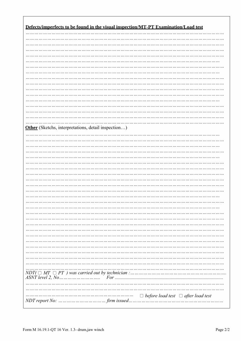
Form M 16.19.1-QT 16 Ver. 1.3- drum,jaw winch Page 2/2
Defects/imperfects to be found in the visual inspection/MT-PT Examination/Load test ………………………………………………………………………………………………………………………… ………………………………………………………………………………………………………………………… ………………………………………………………………………………………………………………………… ………………………………………………………………………………………………………………………… ………………………………………………………………………………………………………………………… ……………………………………………………………………………………………………………………… ………………………………………………………………………………………………………………………… ……………………………………………………………………………………………………………………… ………………………………………………………………………………………………………………………… ………………………………………………………………………………………………………………………… ………………………………………………………………………………………………………………………… ………………………………………………………………………………………………………………………… ……………………………………………………………………………………………………………………… ………………………………………………………………………………………………………………………… ………………………………………………………………………………………………………………………… ………………………………………………………………………………………………………………………… ………………………………………………………………………………………………………………………… Other (Sketchs, interpretations, detail inspection…) ……………………………………………………………………………………………………………………… ………………………………………………………………………………………………………………………… ……………………………………………………………………………………………………………………… ………………………………………………………………………………………………………………………… ……………………………………………………………………………………………………………………… ………………………………………………………………………………………………………………………… ………………………………………………………………………………………………………………………… ………………………………………………………………………………………………………………………… ………………………………………………………………………………………………………………………… ………………………………………………………………………………………………………………………… ………………………………………………………………………………………………………………………… ……………………………………………………………………………………………………………………… ………………………………………………………………………………………………………………………… ……………………………………………………………………………………………………………………… ………………………………………………………………………………………………………………………… ………………………………………………………………………………………………………………………… ………………………………………………………………………………………………………………………… ………………………………………………………………………………………………………………………… ………………………………………………………………………………………………………………………… ………………………………………………………………………………………………………………………… ………………………………………………………………………………………………………………………… ………………………………………………………………………………………………………………………… ………………………………………………………………………………………………………………………… ………………………………………………………………………………………………………………………… ………………………………………………………………………………………………………………………… NDT( MT PT ) was carried out by technician :…………………………………………………………. ASNT level 2, No……………………….. For ......................................................................................... ………………………………………………………………………………………………………………………… ………………………………………………………………………………………………………………………… ………………………………………………………………… before load test after load test NDT report No: …………………………… firm issued…………………………………………………………

Form M 16.20.1- QT 16 Ver. 1.3- Jack report Page 1/2
CISR
CENTER OF INDUSTRIAL SAFETY
REGISTRATION ZONE 2
6 floor, Citilight tower, 45 Vo Thi Sau Dakao Ward, District 1, HCM City
Tel : 083.8275301‐064.615653 Fax: 083.8275300‐064.592665
Website : www.kiemdinh.vn ;
REPORT OF INSPECTION/EXAMINATION/TESTING FOR HYDRAULIC/MECHANICAL JACK
Work order No. :……………………..Date :……………..
Location :Client/ owner
Name : Address
References Inspection procedure QT 16 – Lifting equipments inspection/testing procedure Codes/Standards
Testing Equipments to be used for examination/testing:Ser/ID Number Description of Equipment Calibrated cert. No Valid until
DETAIL OF INSPECTION/EXAMINATION/TESTING
No. of equipment to be inspected 1 2 3
Type/Model of equipment Hydraulic Jack
NITO-K3
Serial/ID No. 2222
Rated load-Safe working load (SWL) 3 t
Working height 6m
Manufacturer CROSBY Date of manufacturer 2000
Type, result of inspection/examination Visual NDT Visual NDT Visual NDT +Marking and Identification s
+Housing, bolts-nuts, pins.. s s
+Swivel head, adj. screw s
+Paw and rack s + Rack teeth
+Lifting Screw(bend, crack, thread..) s s
+ Plunger, piston rod
+Leaking hydraulic fluid s
+ Hand pressure pump
+Pressure vavle, pressure gauge Funtioning test
Static test (test load = 1,5x SWL )
Dynamic load test (test load = 1,1SWL) (2,0SWL=20t) ,S
Assessments : Accept Repair Reject
Accept Repair Reject
Accept Repair Reject
Next recommended inspection We certify that the above particulars are correct, and that the examination and test was carried out by the competent person in the manner set forth on the applied procedure/standards.
Inspector/Examiner :…………………….. Witness :………………………………….. Signature :…………………………………. Signature :………………………………….
Remarks: Use reverside for more description, recommendation,interpretation.. if need ; (*) Use reverside or appropriate form in the procedure QT16 for detail inspection if need.;N/A : Not applicable ; S : it is sastisfactory ; R : it isn’t sastisfactory

Form M 16.20.1- QT 16 Ver. 1.3- Jack report Page 2/2
Defects/imperfects to be found in the visual inspection/MT-PT Examination/Load test ………………………………………………………………………………………………………………………… ………………………………………………………………………………………………………………………… ………………………………………………………………………………………………………………………… ………………………………………………………………………………………………………………………… ………………………………………………………………………………………………………………………… ……………………………………………………………………………………………………………………… ………………………………………………………………………………………………………………………… ……………………………………………………………………………………………………………………… ………………………………………………………………………………………………………………………… ………………………………………………………………………………………………………………………… ………………………………………………………………………………………………………………………… ………………………………………………………………………………………………………………………… ……………………………………………………………………………………………………………………… ………………………………………………………………………………………………………………………… ………………………………………………………………………………………………………………………… ………………………………………………………………………………………………………………………… ………………………………………………………………………………………………………………………… Other (Sketchs, interpretations, detail inspection…) ……………………………………………………………………………………………………………………… ………………………………………………………………………………………………………………………… ……………………………………………………………………………………………………………………… ………………………………………………………………………………………………………………………… ……………………………………………………………………………………………………………………… ………………………………………………………………………………………………………………………… ………………………………………………………………………………………………………………………… ………………………………………………………………………………………………………………………… ………………………………………………………………………………………………………………………… ………………………………………………………………………………………………………………………… ………………………………………………………………………………………………………………………… ……………………………………………………………………………………………………………………… ………………………………………………………………………………………………………………………… ……………………………………………………………………………………………………………………… ………………………………………………………………………………………………………………………… ………………………………………………………………………………………………………………………… ………………………………………………………………………………………………………………………… ………………………………………………………………………………………………………………………… ………………………………………………………………………………………………………………………… ………………………………………………………………………………………………………………………… ………………………………………………………………………………………………………………………… ………………………………………………………………………………………………………………………… ………………………………………………………………………………………………………………………… ………………………………………………………………………………………………………………………… ………………………………………………………………………………………………………………………… NDT( MT PT ) was carried out by technician :…………………………………………………………. ASNT level 2, No……………………….. For ......................................................................................... ………………………………………………………………………………………………………………………… ………………………………………………………………………………………………………………………… ………………………………………………………………… before load test after load test NDT report No: …………………………… firm issued…………………………………………………………

Form M 16.21.1- QT 16 Ver. 1.3- offshore crane Page 1/2
CISR CENTER OF INDUSTRIAL SAFETY
REGISTRATION ZONE 2
6 floor,Citilight tower,45 Vo Thi Sau Dakao Ward, District 1, HCM City Tel : 028. 38275301-0254. 3592665 Fax: 028. 38275300-0254. 3592665
Website : www.kiemdinh.vn ;
REPORT OF INSPECTION/PROOF LOAD TESTING
FOR SHIPBOARD/OFFSHORE CRANE
Work order No. :……………………..Date :…………….. Location :………………………………………………….
Client/ owner
Name : Address
References Inspection procedure QT 16 – Lifting equipments inspection/testing procedure Codes/Standards
Testing Equipments to be used for examination/testing: Ser/ID Number Description of Equipment Calibrated cert. No Valid until
CRANE INSPECTION/LOADTEST CHECKLIST
TYPE OF SURVEY : Visual/ overall survey Function test and proof load test Date :………………….
OWNER : ADDRESS : TYPE OF CRANE: DATE OF MFG: MODEL: SERIAL No. : SWL : RADIUS: PLACE: DATE OF SURVEY:
…………………………………………………………………………………......... ……………………………………………………………………………………….. ……………………………………………………………………………………….. ……………………………………………………………………………………….. ……………………………………………………………………………………….. ………………………………………………………………………………………. ……………………………………………………………………………………….. ………………………………………………………………………………………. ……………………………………………………………………………………… ………………………………………………………………………………………
1. OVERALL SURVEY (CRANE ITEM) (*) HOOK BLOCK (*) OPERATOR CAB 1.33 MAIN HOIST HOOK 1.1 GENERAL CONDITION 1.34 WHIP HOIST HOOK 1.2 IDENTIFICATION OF CONTROLS 1.35 BOOM HOIST BUCKET 1.3 SAFETY LABEL WIRES 1.4 CAPACITY CHART/TABLE 1.36 MAIN HOIST
STRUCTURE 1.37 WHIP HOIST
1.5 LADDERS GRATING AND ACCESS
1.38 BOOM TOPPING
1.6 MAIN PEDESTAL, MOUNTING BOLTS
LUBRICATION
1.7 MAIN BOOM 1.39 RUNNING GEAR 1.8 JIB BOOM 1.40 MACHINERY 1.9 ROTATING MOUNTING BOLTS 1.41 WIRE & RIGGING
1.10 FOOT SECTION 2. FUNCTION TESTING 1.11 COUNTER WEIGHT
2.1 INSTRUMENTS AT CABIN, LIGHTS 1.12 BOOM HYDRAULIC CYLINDER SHEAVES AND RUNNING GEAR SEFETY DEVICES 1.13 BOOM HEEL PINS 2.2 ANTI -TWO BLOCK SYSTEM 1.14 BOOM TOPPING HOIST SHEAVES 2.3 SAFE LOAD METER/CUT-OUT 1.15 BOOM WHIP LINE SHEAVES 2.4 MAIN HOIST SLACK WIRE CUT-OUT 1.16 BOOM MAIN HOIST SHEAVES 2.5 WHIP HOIST SLACK WIRE CUT-OUT
1.17 COLUMN WHIP LINE SHEAVES 2.6 MAIN HOIST UPPER LIMITED CUT-OUT
1.18 COLUMN BOOM TOPPING 2.7 WHIT HOIST UPPER LIMITED CUT-
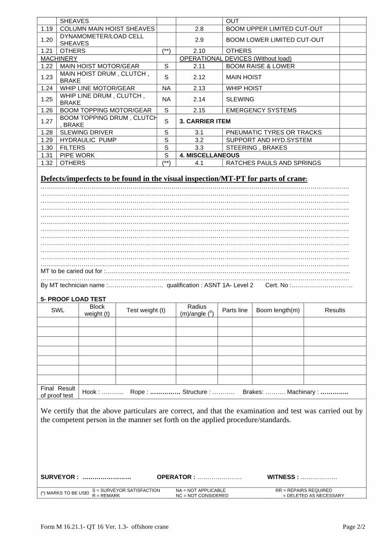
Form M 16.21.1- QT 16 Ver. 1.3- offshore crane Page 2/2
SHEAVES OUT 1.19 COLUMN MAIN HOIST SHEAVES 2.8 BOOM UPPER LIMITED CUT-OUT
1.20 DYNAMOMETER/LOAD CELL SHEAVES
2.9 BOOM LOWER LIMITED CUT-OUT
1.21 OTHERS (**) 2.10 OTHERS MACHINERY OPERATIONAL DEVICES (Without load) 1.22 MAIN HOIST MOTOR/GEAR S 2.11 BOOM RAISE & LOWER
1.23 MAIN HOIST DRUM , CLUTCH , BRAKE
S 2.12 MAIN HOIST
1.24 WHIP LINE MOTOR/GEAR NA 2.13 WHIP HOIST
1.25 WHIP LINE DRUM , CLUTCH , BRAKE
NA 2.14 SLEWING
1.26 BOOM TOPPING MOTOR/GEAR S 2.15 EMERGENCY SYSTEMS
1.27 BOOM TOPPING DRUM , CLUTCH, BRAKE
S 3. CARRIER ITEM
1.28 SLEWING DRIVER S 3.1 PNEUMATIC TYRES OR TRACKS 1.29 HYDRAULIC PUMP S 3.2 SUPPORT AND HYD.SYSTEM 1.30 FILTERS S 3.3 STEERING , BRAKES 1.31 PIPE WORK S 4. MISCELLANEOUS 1.32 OTHERS (**) 4.1 RATCHES PAULS AND SPRINGS
Defects/imperfects to be found in the visual inspection/MT-PT for parts of crane: ……………………………………………………………………………………………………………………………………. ……………………………………………………………………………………………………………………………………. ……………………………………………………………………………………………………………………………………. ……………………………………………………………………………………………………………………………………. ……………………………………………………………………………………………………………………………………. ……………………………………………………………………………………………………………………………………. ……………………………………………………………………………………………………………………………………. ……………………………………………………………………………………………………………………………………. ……………………………………………………………………………………………………………………………………. ……………………………………………………………………………………………………………………………………. ……………………………………………………………………………………………………………………………………. ……………………………………………………………………………………………………………………………………. MT to be caried out for :………………………………………………………………………………………………………... ……………………………………………………………………………………………………………………………………. By MT technician name :……………………… qualification : ASNT 1A- Level 2 Cert. No :………………………… 5- PROOF LOAD TEST
SWL Block
weight (t) Test weight (t)
Radius (m)/angle (0)
Parts line Boom length(m) Results
Final Result of proof test
Hook : ……….. Rope : …………… Structure : ……….. Brakes: ………. Machinary : …………..
We certify that the above particulars are correct, and that the examination and test was carried out by the competent person in the manner set forth on the applied procedure/standards.
SURVEYOR : …………………… OPERATOR : …………………. WITNESS : ……………… (*) MARKS TO BE USED
S = SURVEYOR SATISFACTION R = REMARK
NA = NOT APPLICABLE NC = NOT CONSIDERED
RR = REPAIRS REQUIRED = DELETED AS NECESSARY

Form M 16.22.1-QT 16 Ver. 1.3- donut personal rescue system Page 1/2
CISR CENTER OF INDUSTRIAL SAFETY
REGISTRATION ZONE 2
6 floor, Citilight tower, 45 Vo Thi Sau Dakao Ward, District 1, HCM City Tel : 028. 38275301-0254. 3592665 Fax: 028. 38275300-0254. 3592665
Website : www.kiemdinh.vn ;
REPORT OF INSPECTION/EXAMINATION/TESTING
FOR DONUT PERSONAL RESCUE SYSTEM
Work order No. :……………………..Date :…………….. Location :
Client/ owner
Name : Address
References Inspection procedure QT 16 – Lifting equipments inspection/testing procedure Codes/Standards
Testing Equipments to be used for examination/testing: Ser/ID Number Description of Equipment Calibrated cert. No Valid until
DETAIL OF INSPECTION/EXAMINATION/TESTING
equipment to be inspected Result Remark
Type/Model of equipment DRUM WINCH
NITO-K3
Serial/ID No. 2222 Class of descender Descent height 3 t Descent load 6m Manufacturer CROSBY Date of manufacturer 2000 Type, result of inspection/examination Visual NDT Test Result +Marking and Identification s +Packing, vacuum situation s s + Descender +Hook-anchorage, shackles s +Wire rope, fibre loaded rope s + Wire rope clamping machanism +Wire rope terminations s s +Safety Device s + Connectors +Harnness Static strength test for parts
Function test for descender
Test height: ….m ; Test 1: Maximum Test load: ………kg , descent time :……(s) Test 2: Minimum Test load: 30 kg , descent time :……(s) Calculated velocity of descent for test 1: ……...m/s Calculated velocity of descent for test 1: ……...m/s
Assessments : Accept Repair Reject
Next recommended inspection
We certify that the above particulars are correct, and that the examination and test was carried out by the competent person in the manner set forth on the applied procedure/standards.
Inspector/Examiner :…………………….. Witness :………………………………….. Signature :…………………………………. Signature :………………………………….

Form M 16.22.1-QT 16 Ver. 1.3- donut personal rescue system Page 2/2
Remarks: Use reverside for more description, recommendation,interpretation.. if need ; (*) Use reverside or appropriate form in the procedure QT16 for detail inspection if need.;N/A : Not applicable ; S : it is sastisfactory ; R : it isn’t sastisfactory
Defects/imperfects to be found in the visual inspection/MT-PT Examination/Load test ………………………………………………………………………………………………………………………………………………………………………………………………………………………………………………………………………………………………………………………………………………………………………………………………………………………………………………………………………………………………………… ………………………………………………………………………………………………………………………… ……………………………………………………………………………………………………………………… ………………………………………………………………………………………………………………………… ……………………………………………………………………………………………………………………… ………………………………………………………………………………………………………………………… ………………………………………………………………………………………………………………………… ……………………………………………………………………………………………………………………………………………………………………………………………………………………………………………………………………………………………………………………………………………………………………………………………………………………………………………………………………………………………………… ………………………………………………………………………………………………………………………… ……………………………………………………………………………………………………………………… ………………………………………………………………………………………………………………………… Other ( Sketchs, interpretations, detail inspections….) ………………………………………………………………………………………………………………………… ……………………………………………………………………………………………………………………………………………………………………………………………………………………………………………………..………………………………………………………………………………………………………………………………………………………………………………………………………………………………………………………………………………………………………………………………………………………………………………………………………………………………………………………………………………………………………… ……………………………………………………………………………………………………………………………………………………………………………………………………………………………………………………………………………………………………………………………………………………………………………………………………………………………………………………………………………………………………………………………………………………………………………………………………………………………………………………………………………………………………………………………………………………………… ………………………………………………………………………………………………………………………… ……………………………………………………………………………………………………………………… ……………………………………………………………………………………………………………………………………………………………………………………………………………………………………………………………………………………………………………………………………………………………………………………………………………………………………………………………………………………………………………………………………………………………………………………………………………………………………………………………………………………………………………………………………………………………… ………………………………………………………………………………………………………………………… ……………………………………………………………………………………………………………………… ………………………………………………………………………………………………………………………… NDT( MT PT) was carried out by technician :…………………………………………………………. ASNT level 2, No……………………….. For ......................................................................................... ………………………………………………………………………………………………………………………… ………………………………………………………………………………………………………………………… ………………………………………………………………………… before load test after load test NDT report No: …………………………… firm issued…………………………………………………………

Form M 16.23.1 - QT 16 Ver. 1.3 – Capstan c/w QRH Page 1/2
CISR CENTER OF INDUSTRIAL SAFETY
REGISTRATION ZONE 2
6 floor,Citilight tower,45 Vo Thi Sau Dakao Ward, District 1, HCM City Tel : 028. 38275301-0254. 3592665 Fax: 028. 38275300-0254. 3592665
Website : www.kiemdinh.vn ;
REPORT OF INSPECTION/EXAMINATION/TESTING FOR CAPSTAN C/W QUICK RELEASE HOOKS (QRH)
Work order No. :……………………..Date :…………….. Location :
Client/ owner
Name : Address
References Inspection procedure QT 16 – Lifting equipments inspection/testing procedure Codes/Standards
Testing Equipments to be used for examination/testing: See reverse side for detail DETAIL OF INSPECTION/EXAMINATION/TESTING
Type/Model of equipment
Serial/ID No. Working load limit (WLL) Numbers of hook Specification of power (electric /hydraulic/pneumatic) Manufacturer Date of manufacturer Type, result of inspection/examination/measurement: Visual/Measurement NDT +Marking and Identification +Housing, support structure, bolts-nuts, rivets, pins.. +Capstan lead/Drum +Capstan motor and gear box; Capstan Brake
+Capstan control box; +Footswitch
+QRH -Hook casting
+Primary trip lever; Manual release lever; Cam roll bearing.
+Pivot pin; Load pin/loadcell.
+ Electrical resistance measurement
+Ground connection resistance measurement
+ Control system Functioning test with unloaded for QRH Functioning test with unloaded for Capstan Static test for hook(test load = 1,25xSWL) See reverse side for detail Dynamic load test for hook(test load = 1,1SWL) See reverse side for detail
Assessments : Accept Repair Reject
Next recommended inspection
We certify that the above particulars are correct, and that the examination and test was carried out by the competent person in the manner set forth on the applied procedure/standards.
Inspector/Examiner:…………………….. Witness:………………………………….. Signature :…………………………………. Signature :……………………………. Remarks: Use reverside for more description, recommendation,interpretation.. if need ; (*) Use reverside or appropriate form in the procedure QT16 for detail inspection if need.;N/A : Not applicable ; S : it is sastisfactory ; R : it isn’t sastisfactory

Form M 16.23.1 - QT 16 Ver. 1.3 – Capstan c/w QRH Page 2/2
1- Defects/imperfects to be found in the visual inspection/MT-PT Examination/Load test ………………………………………………………………………………………………………………………………………………………………………………………………………………………………………………………………………………………………………………………………………………………………………………………………………………………………………………………………………………………………………… ………………………………………………………………………………………………………………………… ……………………………………………………………………………………………………………………… ………………………………………………………………………………………………………………………… ……………………………………………………………………………………………………………………… ………………………………………………………………………………………………………………………… ………………………………………………………………………………………………………………………… ……………………………………………………………………………………………………………………………………………………………………………………………………………………………………………………………………………………………………………………………………………………………………………………………………………………………………………………………………………………………………… ………………………………………………………………………………………………………………………… ……………………………………………………………………………………………………………………… ………………………………………………………………………………………………………………………… 2- Testing Record
Equipment/tool to be used for testing
Serial/ID Number Description of
Equipment Calibrated cert. No Valid until
Type of test Applied Standard Required Test
Load/Test Force Real Test Load/Force
Tested Result
Function test Pass Reject
Static load test for hook
Pass Reject
Dynamic load test for hooks
Pass Reject
Note: if the test is not passed, carefully record all of defects such as broken, deformation, crack… in Item 1.
……………………………………………………………………………………………………………………… ………………………………………………………………………………………………………………………… NDT( MT PT) was carried out by technician:…………………………………………………………. ASNT level 2, No……………………….. For ........................................................................................ ………………………………………………………………………………………………………………………… ………………………………………………………………………………………………………………………… ………………………………………………………………………… before load test after load test NDT report No: …………………………… firm issued…………………………………………………………

Form M 16.24.1 - QT 16 Ver. 1.3 – Capstan c/w QRH Page 1/2
CISR CENTER OF INDUSTRIAL SAFETY
REGISTRATION ZONE 2
6 floor, Citilight tower, 45 Vo Thi Sau Dakao Ward, District 1, HCM City Tel : 028. 38275301-0254. 3592665 Fax: 028. 38275300-0254. 3592665
Website : www.kiemdinh.vn ;
REPORT OF INSPECTION/EXAMINATION/TESTING FOR CAPSTAN C/W QUICK RELEASE HOOKS (QRH)
Work order No. :……………………..Date :…………….. Location :
Client/ owner
Name : Address
References Inspection procedure QT 16 – Lifting equipments inspection/testing procedure Codes/Standards
Testing Equipments to be used for examination/testing: See reverse side for detail DETAIL OF INSPECTION/EXAMINATION/TESTING
Type/Model of equipment
Serial/ID No. Manufacturer. Date of manufacturer. Specific condition (Vertical, horizontal, inclined) Type, result of inspection/examination/measurement: Visual/Measurement NDT +Marking and Identification +Housing, bolts-nuts, rivets, pins.. +Hardware such as: connector, rings, swivel, hooks
- Connector - Rings/Bolt; Swivel - Hooks
+Brake mechanism and its operation
+Life line: wire rope, webbing/synthetic rope
+ Termination of life line;
+Shock pack: Lanyard/ webbing;
+Shock pack: Impact indicator ;
Functioning test with light load for RFA Dynamic Performance Test (Test load 100kg) See reverse side for detail
Assessments : Accept Repair Reject
Next recommended inspection
We certify that the above particulars are correct, and that the examination and test was carried out by the competent person in the manner set forth on the applied procedure/standards.
Inspector/Examiner:…………………….. Witness:………………………………….. Signature :…………………………………. Signature :……………………………. Remarks: Use reverside for more description, recommendation,interpretation.. if need ; (*) Use reverside or appropriate form in the procedure QT16 for detail inspection if need.;N/A : Not applicable ; S : it is sastisfactory ; R : it isn’t sastisfactory

Form M 16.24.1 - QT 16 Ver. 1.3 – Capstan c/w QRH Page 2/2
1- Defects/imperfects to be found in the visual inspection/MT-PT Examination/Load test ………………………………………………………………………………………………………………………………………………………………………………………………………………………………………………………………………………………………………………………………………………………………………………………………………………………………………………………………………………………………………… ………………………………………………………………………………………………………………………… ……………………………………………………………………………………………………………………… ………………………………………………………………………………………………………………………… ……………………………………………………………………………………………………………………… ………………………………………………………………………………………………………………………… ………………………………………………………………………………………………………………………… ……………………………………………………………………………………………………………………………………………………………………………………………………………………………………………………………………………………………………………………………………………………………………………………………………………………………………………………………………………………………………… ………………………………………………………………………………………………………………………… ……………………………………………………………………………………………………………………… ………………………………………………………………………………………………………………………… 2- Testing Record
Equipment/tool to be used for testing
Serial/ID Number Description of
Equipment Calibrated cert. No Valid until
Type of test Applied Standard Required Test
Load/Test Force Real Test Load/Force
Tested Result
Function test Pass Reject
Dynamic performance test
Pass Reject
Note: if the test is not passed, carefully record all of defects such as broken, deformation, crack… in Item 1.
……………………………………………………………………………………………………………………… ………………………………………………………………………………………………………………………… NDT( MT PT) was carried out by technician:…………………………………………………………. ASNT level 2, No……………………….. For ........................................................................................ ………………………………………………………………………………………………………………………… ………………………………………………………………………………………………………………………… ………………………………………………………………………… before load test after load test NDT report No: …………………………… firm issued…………………………………………………………

Note : · ·
(*)This should be changed by the specified name of equipment which have been examined/testedUse the vietnamese-english tilte paper for this form
Form M 16.1.2-QT 16 Ver. 1.3- lifted equipment certificate.
CERTIFICATE OF TEST / THOROUGH EXAMINATION FOR LIFTED EQUIPMENTS *
Cert. No. /TN/KĐ2
Date Ref.No.
Client Name : Address
Owner References
Procedure QT 16 – Lifting equipments inspection/testing procedureCodes/Standards IMCA M 179, Guidance on the use of cable laid slings and
grommets Date of examination/test : 19/ 05/2010 Place : PTSC Supply base – Vung tau-Viet namReason for issuing the certificate : initial certificate Recertificate After repair other (given reason) :…………………………………………………………………………………..
Type and model : OFFSHORE CONTAINER ; LONG BASKET; MACHINERY SUPPORTED FRAME…
Manufacturer :……………………………………………………….Serial/ID number :…………………………
Max.gross mass (Rating) R(tonne)
…………………….
Tare mass (T)(tonne)
………………………..
Payload (P)(tonne)
……………………
Externaldimension(LxWxH) ……………………..
Test load applied(2,5R)……………………. ……………………..
Testload applied (1,5R)……………………….. ………………………..
Max.angle of legs sling (from vertical- degree) …………………….
Min.shackle boltdiameter (mm)
……………………
Inspection/Examination/Testing Result Remarks The lifting appliances has been visually inspected and MT examinated as follow:
Marking : With data tag attached dimentional : suitable with design technical document Visual check for defects : it in good situation, free from any defects MT examination: MT was carried out for all surface of body and pin shackle
Passed
Assessments : That lifted equipment were examined/load tested and found to be in good condition, theexamination after the test showed that the said equipment withstood the proof load and free from permanent deformation or other defects. Recommended for next examination/test : Visual inspectionRemarks : The expression “tonne” shall mean a tonne or 1000kg.
We certify that the above particulars are correct, and that the examination and test was carried out by the competent person in the manner set forth on the applied procedure/standards.
Inspector/Examiner For CISR Director

Note : · ·
(*)This should be changed by the specified name of equipment which have been examined/testedUse the vietnamese-english tilte paper for this form
Form M 16.2.2 – QT 16 Ver. 1.3- lifting appliance certificate
CERTIFICATE OF TEST / THOROUGH EXAMINATION FOR LIFTING APPLIANCES*
Cert. No. : ………………………./TN/KĐ2Date : ……………………… Ref. report No. : ………………………
Client Name : Address
Owner References
Procedure QT 16 – Lifting equipments inspection/testing procedureCodes/Standards IMCA M 179, Guidance on the use of cable laid slings and
grommets Date of examination/test : 19/ 05/2010 Place : PTSC Supply base – Vung tau-Viet namReason for issuing the certificate : initial certificate Recertificate After repair other (given reason) :…………………………………………………………………………………..
(1) Distinguishing
Mark/No.
(2) Situation and description of lifting
appliance(type, model, manufacturer, specification ..) which have been tested and
thorough examined
(3) Angle to the horizontal or
radius at which test load applied
(4) Proof test
load applied (tonnes)
(5) Safe working load at design angle (SWL-
tonnes)
Inspection/Examination/Testing Result Remarks
The lifting appliances has been visually inspected and MT examinated as follow: Marking : With data tag attached dimentional : suitable with design technical document Visual check for defects : it in good situation, free from any defects MT examination: MT was carried out for all surface of body and pin shackle
Passed
Assessments : That lifting appliance were examined/load tested and found to be in good condition, theexamination after the test showed that the said equipment withstood the proof load and free from permanent deformation or other defects and it safe working load is as show in column (5). Recommended for next examination/test : Visual inspectionRemarks : The expression “tonne” shall mean a tonne or 1000kg.
We certify that the above particulars are correct, and that the examination and test was carried out by the competent person in the manner set forth on the applied procedure/standards.
Inspector/Examiner For CISR Director

Note : · ·
(*)This should be changed by the specified name of equipment which have been examined/testedUse the vietnamese-english tilte paper for this form
Form M 16.3.2- QT 16 Ver. 1.3 - rigging certificate.
CERTIFICATE OF TEST / THOROUGH EXAMINATION FOR LOOSE GEAR( RIGGING)
Cert. No. /TN/KĐ2
Date Ref.No.
Client Name : Address
Owner References
Inspectionprocedure
QT 16 – Lifting equipments inspection/testing procedure
Codes/Standards IMCA M 179, Guidance on the use of cable laid slings and grommetsDate of examination/test : 19/ 05/2010 Place : PTSC Supply base – Vung tau-Viet nam
Reason for issuing the certificate : initial certificate Recertificate After repair (1)
Distinguishing Mark/No.
(2) Situation and description of gear (type,
model, the dimensions of gear, material of which it made..)
(4) Number tested
(5) Proof test
load applied (tonnes)
(6) Safe working load at design angle (SWL-
tonnes)
Inspection/Examination/Testing Result Remarks
The loose gear has been visually inspected and MT examinated as follow:Marking : With data tag attached dimentional : Both end soft Eye, free from any defects Visual check for defect : it in good situation, free from any defects MT examination: MT was carried out for all surface of body and pin shackle
Passed
Assessments : That loose gear were examined/load tested and found to be in good condition, theexamination after the test showed that the said loose gear withstood the proof load and free from permanent deformation or other defects and it safe working load is as show in column (6). Recommended for next examination/test : Visual inspectionRemarks : See reverse side or refer to the Ref.Report mentioned above for more details. The expression “tonne” shall mean a tonne or 1000kg.
We certify that the above particulars are correct, and that the examination and test was carried out by the competent person in the manner set forth on the applied procedure/standards.
Inspector/Examiner For CISR Director