Queensland Electricity Connection Manual · 2019-11-21 · Queensland Electricity Connection Manual...
124
Transcript of Queensland Electricity Connection Manual · 2019-11-21 · Queensland Electricity Connection Manual...

Queensland Electricity Connection Manual
Check this is the latest version before use. EX Manual 01811 Ver 2 EE NA000403R509 Ver 2
Joint document between Energex and Ergon Energy Energex Limited ABN 40 078 849 055 Ergon Energy Corporation Limited ABN 50 087 646 062
THIS PAGE HAS BEEN DELIBERATELY LEFT BLANK
Queensland Electricity Connection Manual
Check this is the latest version before use. i EX Manual 01811 Ver 2 EE NA000403R509 Ver 2
Joint document between Energex and Ergon Energy Energex Limited ABN 40 078 849 055 Ergon Energy Corporation Limited ABN 50 087 646 062
Table of Contents
Distributors Contact Details ..................................................................................... 1 Dial Before You Dig ................................................................................................... 1 Foreword .................................................................................................................... 3 Purpose and Scope ................................................................................................... 4 Definitions, Abbreviations and Acronyms .............................................................. 4 References ................................................................................................................. 4 Responsibilities ......................................................................................................... 5 1. Important Information ....................................................................................... 16
Use of this document ......................................................................................... 16 1.1. Scope ................................................................................................................ 16 1.2. Failure to comply with this manual ..................................................................... 17 1.3. Exceptional Circumstances ................................................................................ 17 1.4. Enquiries ........................................................................................................... 17 1.5. Distributors Contact Details for QECM Correspondence .................................... 18 1.6. Historic Buildings and Flora with Vegetation Protection Orders.......................... 18 1.7. Revisions and alterations ................................................................................... 18 1.8. Drawings ........................................................................................................... 18 1.9.
2. Customers Installations ................................................................................... 20 Request for Electrical Connection ...................................................................... 20 2.1. Request for Initial Connection, Service Alteration, Metering Change or Inverter 2.2.
change............................................................................................................... 20 Alterations and Additions ................................................................................... 21 2.3. Breaking of Metering Terminal Cover/Metering Isolation Link/Metering Neutral 2.4.
Link Seals .......................................................................................................... 21 Examination, Test and Connection .................................................................... 22 2.5. Unmetered Supplies .......................................................................................... 22 2.6. Identification in Multiple Installations .................................................................. 22 2.7. Protective Fault Current Devices ....................................................................... 22 2.8. Power Factor ..................................................................................................... 23 2.9.
Limitations on Starting Currents of AC Motors ................................................... 23 2.10. Interference with Supply of Electricity to Other Customers ................................. 25 2.11. High Voltage Installations .................................................................................. 25 2.12. Customer's Generating Systems ....................................................................... 26 2.13. Determination of Maximum Demand .................................................................. 26 2.14. Requirement for Circuit Breakers in Rural/Isolated Areas .................................. 26 2.15.
3. Determination of the Number of Phases to be Installed ................................ 28 General .............................................................................................................. 28 3.1. Urban Areas ...................................................................................................... 28 3.2. Non-Urban Areas ............................................................................................... 28 3.3.
4. Balancing of Load and Limitation on Equipment ........................................... 30 General .............................................................................................................. 30 4.1. Connection of Equipment - Current Limitations .................................................. 30 4.2. Equipment Having Fluctuating Loads................................................................. 31 4.3. Harmonic Interference or Wave Form Distortion ................................................ 31 4.4. Rectifiers ........................................................................................................... 32 4.5. Connection of Equipment - Voltage Limitations .................................................. 32 4.6.
Queensland Electricity Connection Manual
Check this is the latest version before use. ii EX Manual 01811 Ver 2 EE NA000403R509 Ver 2
Joint document between Energex and Ergon Energy Energex Limited ABN 40 078 849 055 Ergon Energy Corporation Limited ABN 50 087 646 062
Connection of Equipment - Isolated Generation Localities ................................. 32 4.7.5. Service Lines and Connection point ............................................................... 34
General .............................................................................................................. 34 5.1. Connection point ................................................................................................ 34 5.2. Service Lines ..................................................................................................... 34 5.3. Overhead Service Lines .................................................................................... 35 5.4. Underground Service Lines ............................................................................... 40 5.5. Additional Service Lines in Urban Areas ............................................................ 42 5.6. Additional Service Lines in Non-Urban Areas .................................................... 42 5.7. Alterations to Service Lines ............................................................................... 42 5.8. Consumer’s mains on the Distributor’s Poles ..................................................... 43 5.9.
Substations on Customer's Premises ................................................................ 43 5.10. Joints in Consumer’s mains ............................................................................... 44 5.11.
6. Metering Requirements .................................................................................... 62 General .............................................................................................................. 62 6.1. Controlled loads ................................................................................................. 62 6.2. Metering Isolation .............................................................................................. 62 6.3. Metering Active and Neutral Requirements ........................................................ 66 6.4. Metering and Control Equipment - Accommodation ........................................... 68 6.5. Metering and Control Equipment - Position ........................................................ 68 6.6. Metering and Control Equipment - Housing ....................................................... 72 6.7. Metering and Control Equipment – Spacing Requirements ................................ 73 6.8. Metering and Control Equipment - Mounting ...................................................... 74 6.9.
Metering Locks .................................................................................................. 75 6.10. Current Transformer Equipment supplied by the Distributor ............................... 75 6.11. Current Transformer Metering – Housing ........................................................... 75 6.12. Changes to Existing Current Transformer Metering Installations........................ 76 6.13.
Electrical Contractor’s LV CT Metering Check Sheet .................................................... 77 7. Controlled Supplies - Method of Control ........................................................ 84
General .............................................................................................................. 86 7.1. Network Devices ................................................................................................ 86 7.2. Contactor for Control of Non-Continuous Load .................................................. 87 7.3. Size of Network Device Wiring ........................................................................... 87 7.4.
8. Arrangements for Embedded Generating Systems Connected to the Distribution Network ............................................................................................... 98
Explanation of Metering Schemes Available ...................................................... 98 8.1. Agreements ....................................................................................................... 98 8.2. Approval of Equipment ...................................................................................... 98 8.3. Connection Requirements for EG Systems ........................................................ 99 8.4. Labelling Requirements to AS/NZS 4777.1 ........................................................ 99 8.5.
9. High Voltage Metering .................................................................................... 102 General Requirements ..................................................................................... 102 9.1. Testing Requirements ...................................................................................... 102 9.2. Operation of High Voltage Equipment .............................................................. 102 9.3. Maintenance and Repairs of High Voltage Equipment ..................................... 102 9.4. Conversion from Low Voltage Supply to High Voltage Supply ......................... 102 9.5. Metering Requirements ................................................................................... 103 9.6. Establishing a Network Connection and NMI ................................................... 103 9.7.
Queensland Electricity Connection Manual
Check this is the latest version before use. iii EX Manual 01811 Ver 2 EE NA000403R509 Ver 2
Joint document between Energex and Ergon Energy Energex Limited ABN 40 078 849 055 Ergon Energy Corporation Limited ABN 50 087 646 062
Offer of Supply Letter and/or Network Connection Agreement ......................... 103 9.8. Connection point .............................................................................................. 103 9.9.
Revenue Metering ........................................................................................... 104 9.10. Meter Enclosure .............................................................................................. 105 9.11. Secondary Wiring ............................................................................................ 106 9.12.
Appendix A - Specification for Metallic Enclosures for Meters in Direct Connected Installations ........................................................................................ 108
A.1 Scope and General .......................................................................................... 108 A.2 Design and Construction ................................................................................. 108 A.3 Dimensions ...................................................................................................... 110
Appendix B - Glossary of Terms .......................................................................... 112 Appendix C - Amendment Record ....................................................................... 118

Queensland Electricity Connection Manual
Check this is the latest version before use. Page 1 of 118 EX Manual 01811 Ver 2 EE NA000403R509 Ver 2
Joint document between Energex and Ergon Energy Energex Limited ABN 40 078 849 055 Ergon Energy Corporation Limited ABN 50 087 646 062
DISTRIBUTORS CONTACT DETAILS Energex
Web Address www.energex.com.au
CT Metering Order Form www.energex.com.au/service_providers/electrical_contractors.html
General Customer Service
13 12 53
E-mail request can be sent to [email protected]
Loss of Supply 13 62 62
Emergencies 13 19 62
C&I Substation Manual Available from Technical Documents section of Energex website: www.energex.com.au
Metering Locks https://www.energex.com.au/home/our-services/meters/energex-locks
EWR (Form 2) Enquiries/Technical Information - QECM enquiries.
1300 762 397
Ergon Energy
Web Address www.ergon.com.au
EWR (Form A) and CT Metering Order Form
Available from Electrical Contractors section of Ergon Energy website: www.ergon.com.au
General Customer Service
13 74 66 For all areas - New Applications, Point of Attachment Site Visits, Breaking Meter Seals.
E-mail requests can be sent to [email protected] or by completing the Contact Form as provided under “Contact Us” on Ergon Energy’s Web site: www.ergon.com.au
24 Hour Faults and Emergencies
13 22 96
Metering Locks 1300 323 301 toll free number. Metering Locks can be purchased from API Locksmiths (Queensland Locksmiths) by phone or on-line at www.queenslandlocksmiths.com.au .
Technical Information -QECM enquiries.
1800 237 466 Electrical Contractor Hotline (EC Use only)
DIAL BEFORE YOU DIG
Queensland Electricity Connection Manual
Check this is the latest version before use. Page 2 of 118 EX Manual 01811 Ver 2 EE NA000403R509 Ver 2
Joint document between Energex and Ergon Energy Energex Limited ABN 40 078 849 055 Ergon Energy Corporation Limited ABN 50 087 646 062
Phone 1100 - free call (except from mobiles) Fax 1300-652-077
Website www.1100.com.au
Dial before you Dig is the national referral service for information on the location of underground infrastructure.
Australia’s major service providers have a single web-enabled information service for information on the location of underground communications, gas, water and electricity infrastructure.
The Dial before you Dig online service is available 24 hours a day and enables users to have more control over their enquiry as you detail the dig site on the mapping software yourself.
Use the website to ensure that you ‘Dial Before You Dig’ before any excavation work.
When calling the 1100 phone number the operator may require the following:
• your name and address
• name of company
• contact telephone number
• fax number for return information
• contact name on site
• site address and both nearest cross streets
• start date of proposed work
• type of work being carried out
Note: Section 68 of the Electrical Safety Regulation 2013 sets out the duties of persons working near overhead and underground electric lines.

Queensland Electricity Connection Manual
Check this is the latest version before use. Page 3 of 118 EX Manual 01811 Ver 2 EE NA000403R509 Ver 2
Joint document between Energex and Ergon Energy Energex Limited ABN 40 078 849 055 Ergon Energy Corporation Limited ABN 50 087 646 062
FOREWORD The Queensland Electricity Connection Manual (QECM) has been compiled in conjunction with Energex and Ergon Energy and is the same jurisdictional document referred to as the Electricity Connection and Metering Manual (ECMM) in the Metrology Procedure: Part A National Electricity Market. Note: Printed versions of the QECM are “uncontrolled copies” - the latest version is available on the Energex website (www.energex.com.au ) or Ergon Energy website (www.ergon.com.au ).
Safety In all activities undertaken, the safety of our employees, contractors, customers and the community is paramount. Safety is our number one value and there is a commitment to ensuring that "safety must come first" to achieve a no injuries workplace. In accordance with legislative requirements we have developed Policies, Standards and Work Practices that our workers are required to follow to ensure the safety of themselves, other workers, customers and the community. We trust that electrical contractors and persons in control of sites will appreciate that our workers will not undertake any work in a situation where there are uncontrolled risks inconsistent with our safe systems of work.
Disclaimer Whilst the QECM contains material relevant to the electricity industry legislation, codes of practice and standards, it is not intended to provide legal advice on how electrical contractors can meet their own statutory obligations or comply with legislation, codes of practice or industry standards such as AS/NZS 3000 (Wiring Rules).
The QECM does not provide advice for the purposes of section 68 of the Electrical Safety Regulation 2013. The Electrical Safety Act 2002, Electrical Safety Regulation 2013 and associated codes of practice establish requirements for electrical safety and place obligations on employers, self-employed persons and others. These documents may be obtained from the Queensland Government website (www.worksafe.qld.gov.au).
Whilst care has been taken in the preparation of the QECM, the distribution entities do not guarantee that the information contained in the QECM is accurate, complete or up to date at time of publication. To the extent permitted by the relevant legislation the distributor will not be responsible for any loss, damage, cost or expense incurred as a result of any error, omission or misrepresentation in relation to the information contained in the QECM.
Copyright Copyright © 2018 Energex Limited and Ergon Energy Corporation Limited. This publication is copyright. Except as permitted under the Copyright Act 1968 no part of this publication may be reproduced by any process without the specific written permission of the copyright owner.
All rights reserved.
Queensland Electricity Connection Manual
Check this is the latest version before use. Page 4 of 118 EX Manual 01811 Ver 2 EE NA000403R509 Ver 2
Joint document between Energex and Ergon Energy Energex Limited ABN 40 078 849 055 Ergon Energy Corporation Limited ABN 50 087 646 062
PURPOSE AND SCOPE The purpose of this manual is to promote industry uniformity through standardisation of practices throughout Queensland. The document is for use by Electrical Contractors, Consulting Engineers, Architects, Metering Providers and others directly concerned with electrical installations that are connected, or are to be connected, to the respective supply network.
Electrical installation compliance and obligations contained in this manual forms part of the (Queensland) Electricity Distribution Network Code and the National Electricity Rules.
DEFINITIONS, ABBREVIATIONS AND ACRONYMS Unless otherwise stated definitions, abbreviations and acronyms used in AS/NZS 3000 (Wiring Rules) and the current Legislation referenced in the QECM have the same meaning when used in this document.
Refer to the Glossary of Terms for general definitions.
Note: Words and terms defined in the Glossary are identified within the text by italicising (e.g. distributor).
REFERENCES Referenced Legislation: Electricity Act 1994 (Qld) Electricity Regulation 2006 (Qld) Electricity Distribution Network Code (made under the Electricity Act 1994 (Qld)) Electrical Safety Act 2002 (Qld) Electrical Safety Regulation 2013 (Qld) Electrical Safety Code of Practice 2010 – Working near exposed live parts Queensland Government Gazette – Notified Prices (Tariff Gazette, http://www.qca.org.au) Work Health and Safety Act 2011 (Qld) National Electricity Rules Referenced Standards: AS 1243 Voltage transformers for measurement and protection AS/NZS 1269.1 Occupational noise management - Measurement and assessment of
noise immission and exposure AS 1284.4 Electricity metering Socket mounting system AS 1397 Steel sheet and strip - hot dip zinc-coated or aluminium/zinc-coated AS 1657 Fixed platforms, walkways, stairways and ladders - Design construction
and installation AS 2067 Substations and high voltage installations exceeding 1kV ac AS/NZS 3000 Wiring Rules AS/NZS 3012 Electrical installations - Construction and demolition sites AS 4645.1 Gas distribution networks – Network management AS/NZS 4777.1 Grid connection of energy systems via inverters - Installation
requirements AS/NZS 4777.2 Grid connection of energy systems via inverters - Inverter requirements AS 5601 Australian Gas Code AS 6002 Domestic electricity meter enclosures AS 60044 series Instrument transformers
Queensland Electricity Connection Manual
Check this is the latest version before use. Page 5 of 118 EX Manual 01811 Ver 2 EE NA000403R509 Ver 2
Joint document between Energex and Ergon Energy Energex Limited ABN 40 078 849 055 Ergon Energy Corporation Limited ABN 50 087 646 062
AS/NZS 60079.10.1 Classification of hazardous areas - Examples of area classification - Flammable gases
AS 60269 series Low-voltage fuses AS 60529 Degrees of protection provided by enclosures (IP Code) AS 60974.6 Arc welding equipment - Welding power sources AS/NZS 61000 Series Electromagnetic compatibility (EMC) AS/IEC 62196 Plugs, socket-outlets, vehicle connectors and vehicle inlets – Conductive
charging of electric vehicles EE STNW1170/ Connection Standard for Micro Embedded Generating Units (0 – EX STD01143 ≤30 kVA) EE STNW1174 Standard for Connection of Embedded Generating Systems (>30 kW EX STD01618 to 1,500 kW) to a Disitributor’s LV Network STNW1175 Standard for Connection of Embedded Generating Systems to a
Disitributor’s HV Network RESPONSIBILITIES The Customer:
• selects an electricity retailer; • where applicable, negotiates or nominates an agent to negotiate provision of the electricity
supply with the distributor; • contacts their retailer when advised by an electrical contractor; • for initial connections, the customer is responsible to ensure trees are cut/trimmed to provide
clear access for an overhead service; • provides a safe working environment for the electrical contractor, meter reader, etc; • ensures the meter enclosure is accessible at all times. If behind a locked gate ensures that
the gate is fitted with the distributor’s metering lock; • ensures the meter enclosure is clear of vegetation and that the meter reader can read the
meter without stepping on, or damaging valuable plants etc; • ensures that the connection point is clear at all times to allow safe access by the distributor’s
personnel; • notifies the retailer, distributor and metering provider where applicable, when supply is to be
permanently disconnected from a premises (supply abolishment); and • contacts the retailer prior to any work being done that may impact on the metering installation.
The Relevant Distributor:
• negotiates provision of the electricity supply with the customer or the customer’s agent (generally an electrical contractor);
• transports and delivers electricity which is purchased by retailers and sold to customers; • examines and tests the consumer’s mains, main switchboard and main earth of a customer’s
installation before it is initially connected to the distributor’s electricity network; • may be the metering provider, where the transitional provisions apply • provides the Distributor Network Devices; • connects the electricity supply to a customer’s installation up to the load side of the Metering
Isolation Links (subject to rectification of any defects) and subject to the customer selecting a retailer, and the retailer requesting the connection;
• is responsible for the reliability and quality of the electricity supply at the connection point; • is responsible for the issue of NMIs (refer to local distributor’s web site for guidelines).
The Metering Provider:
Queensland Electricity Connection Manual
Check this is the latest version before use. Page 6 of 118 EX Manual 01811 Ver 2 EE NA000403R509 Ver 2
Joint document between Energex and Ergon Energy Energex Limited ABN 40 078 849 055 Ergon Energy Corporation Limited ABN 50 087 646 062
The metering provider must be accredited by AEMO and shall comply with the following responsibilities; • when appointed by the metering coordinator, they are to supply, install and maintain the
metering equipment on a customer’s premises in accordance with this QECM, • to ensure all customer energy is metered and to notify by the appropriate notification form to
the distributor any unmetered circuits identified, • notify the distributor immediately and cease any work if evidence of tampering of metering or
control equipment is detected, • retain or utilise distributor’s network devices where the customer requires controlled tariffs, • where the distributor is the metering provider, comply with distributor’s requirements for
installation, sealing and testing of metering equipment, • where the metering provider is not the distributor, notify the distributor by the appropriate
process prior to conducting any onsite works, • the metering provider shall attach a label to the metering installation detailing the NMI, the
metering provider and metering provider contact details, • ensure that all safety and security requirements are maintained for all types of metering
installations, • inspect and confirm the metering installation is compliant with this QECM and relevant safety
requirements, and issue corrective action notices if defects exist.
The Relevant Retailer:
• purchases electricity and sells it to customers; • nominates prices and negotiates contracts where applicable, for the sale of electricity to
customers; • where the distributor is not the metering provider, provides the distributor with details of the
metering coordinator and/or metering provider; • requests the distributor to connect, disconnect or alter the customer’s installation in
accordance with the customer’s contract (Service Order Request if applicable).
The Electrical Contractor:
• ensures all electrical work is in accordance with Queensland Legislation, AS/NZS 3000 (Wiring Rules), other relevant Standards and the requirements of the QECM (in particular ensuring that unterminated cables cannot be energised by inserting a fuse or link or by closing a switch or circuit breaker);
• where ‛exceptional circumstances’ occur, ensures that permission is obtained by submitting a written request to the distributor for a variation;
• ensures that the distributor is advised when there is a significant increase in the electrical load at an installation;
• advises the customer when increases in load require changes to the electrical installation including meter changes;
• must not work on or remove metering equipment unless they are the appointed metering provider;
• on completion of electrical work that involves metering or metering alterations, advises the customer that they must contact the retailer and notify that the work is complete (See note in Clause 2.2);
• issues the customer with a certificate of testing and compliance; • submits appropriate forms in a timely manner and ensures that the information on the forms is
accurate (e.g. correct address); • notifies the metering provider of any broken metering seals; • notifies the distributor of any broken network device seals; and
Queensland Electricity Connection Manual
Check this is the latest version before use. Page 7 of 118 EX Manual 01811 Ver 2 EE NA000403R509 Ver 2
Joint document between Energex and Ergon Energy Energex Limited ABN 40 078 849 055 Ergon Energy Corporation Limited ABN 50 087 646 062
• rectifies any departures from this manual that have been identified by the distributor/metering provider;
The Electrical Consultant:
• designs the electrical installation in accordance with Queensland Legislation, AS/NZS 3000 (Wiring Rules), other relevant Standards and the requirements of this manual;
• where ‛exceptional circumstances’ occur, ensures that permission is obtained by submitting a written request to the distributor for a variation;
• on large projects liaises with the distributor to ensure adequate supply is available when required;
• ensures that the distributor is advised when there is a significant increase in the electrical load at an installation;
• advises the customer when increases in load require changes to the electrical installation including meter changes.
Stakeholder Interaction Diagrams: The following diagrams have been included as a guide to assist the users of this manual to understand the process interaction between the customer, electrical contractor, retailer, distributor and metering provider:
1) Initial Connection - Direct Connected Metering; 2) Initial Connection - Current Transformer Metering; 3) Electrical Installation Work Involving Metering Changes; 4) Service and Metering Change - Additional Phases; 5) Service Alteration - No Metering Changes; 6) Micro Embedded Generating (EG) Unit Connection to the Distribution Network; 7) Initial Connection - High Voltage Installation.
Queensland Electricity Connection Manual
Check this is the latest version before use. Page 8 of 118 EX Manual 01811 Ver 2 EE NA000403R509 Ver 2
Joint document between Energex and Ergon Energy Energex Limited ABN 40 078 849 055 Ergon Energy Corporation Limited ABN 50 087 646 062
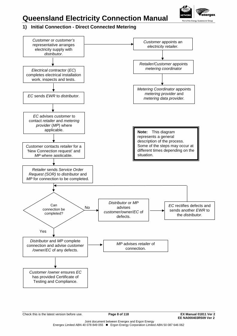
1) Initial Connection - Direct Connected Metering
No
Yes
Customer or customer’s representative arranges
electricity supply with distributor.
Electrical contractor (EC) completes electrical installation
work, inspects and tests.
EC advises customer to contact retailer and metering
provider (MP) where applicable.
Customer contacts retailer for a ‘New Connection request’ and
MP where applicable.
Retailer sends Service Order Request (SOR) to distributor and
MP for connection to be completed.
Distributor or MP advises
customer/owner/EC of defects.
EC rectifies defects and sends another EWR to
the distributor.
Distributor and MP complete connection and advise customer
/owner/EC of any defects. MP advises retailer of
connection.
EC sends EWR to distributor.
Note: This diagram represents a general description of the process. Some of the steps may occur at different times depending on the situation.
Customer /owner ensures EC has provided Certificate of Testing and Compliance.
Can connection be completed?
Customer appoints an electricity retailer.
Retailer/Customer appoints metering coordinator
Metering Coordinator appoints metering provider and metering data provider.
Queensland Electricity Connection Manual
Check this is the latest version before use. Page 9 of 118 EX Manual 01811 Ver 2 EE NA000403R509 Ver 2
Joint document between Energex and Ergon Energy Energex Limited ABN 40 078 849 055 Ergon Energy Corporation Limited ABN 50 087 646 062
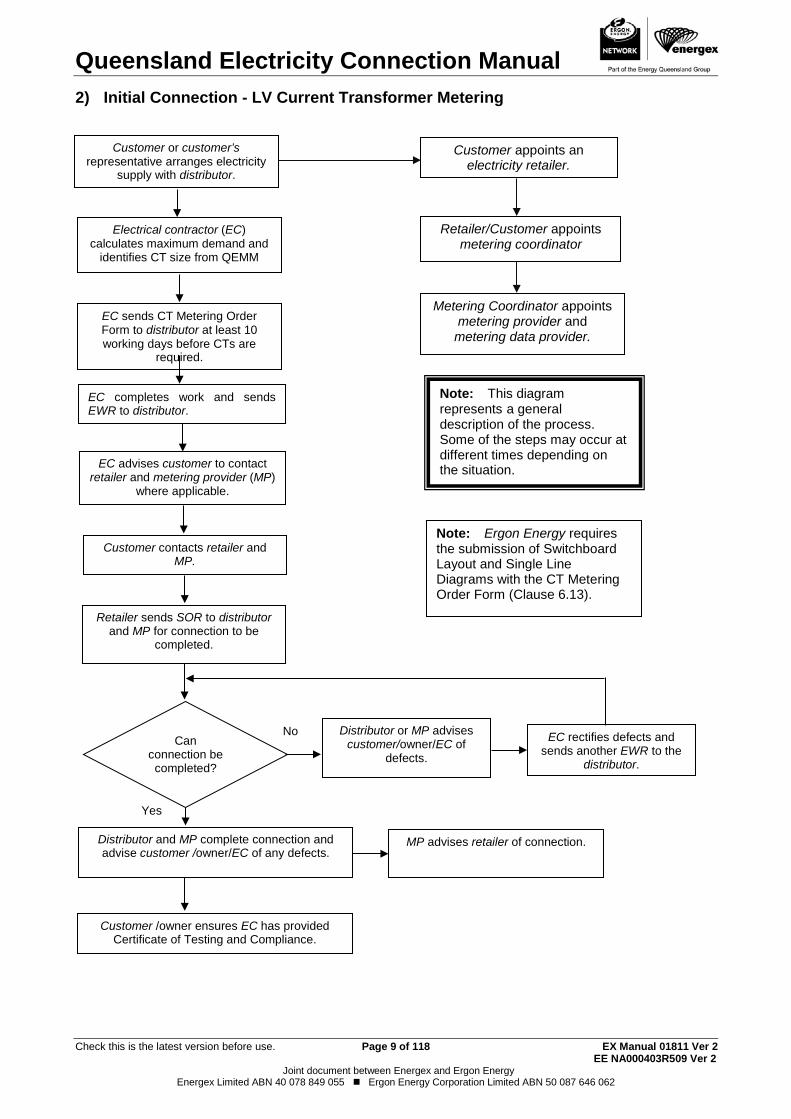
2) Initial Connection - LV Current Transformer Metering
No
Yes
Electrical contractor (EC) calculates maximum demand and
identifies CT size from QEMM
EC sends CT Metering Order Form to distributor at least 10 working days before CTs are
required.
EC advises customer to contact retailer and metering provider (MP)
where applicable.
Customer contacts retailer and MP.
Retailer sends SOR to distributor and MP for connection to be
completed.
Can connection be completed?
Distributor or MP advises customer/owner/EC of
defects.
EC rectifies defects and sends another EWR to the
distributor.
Distributor and MP complete connection and advise customer /owner/EC of any defects. MP advises retailer of connection.
Customer or customer’s representative arranges electricity
supply with distributor.
EC completes work and sends EWR to distributor.
Note: Ergon Energy requires the submission of Switchboard Layout and Single Line Diagrams with the CT Metering Order Form (Clause 6.13).
Note: This diagram represents a general description of the process. Some of the steps may occur at different times depending on the situation.
Customer /owner ensures EC has provided Certificate of Testing and Compliance.
Customer appoints an electricity retailer.
Retailer/Customer appoints metering coordinator
Metering Coordinator appoints metering provider and metering data provider.
Queensland Electricity Connection Manual
Check this is the latest version before use. Page 10 of 118 EX Manual 01811 Ver 2 EE NA000403R509 Ver 2
Joint document between Energex and Ergon Energy Energex Limited ABN 40 078 849 055 Ergon Energy Corporation Limited ABN 50 087 646 062
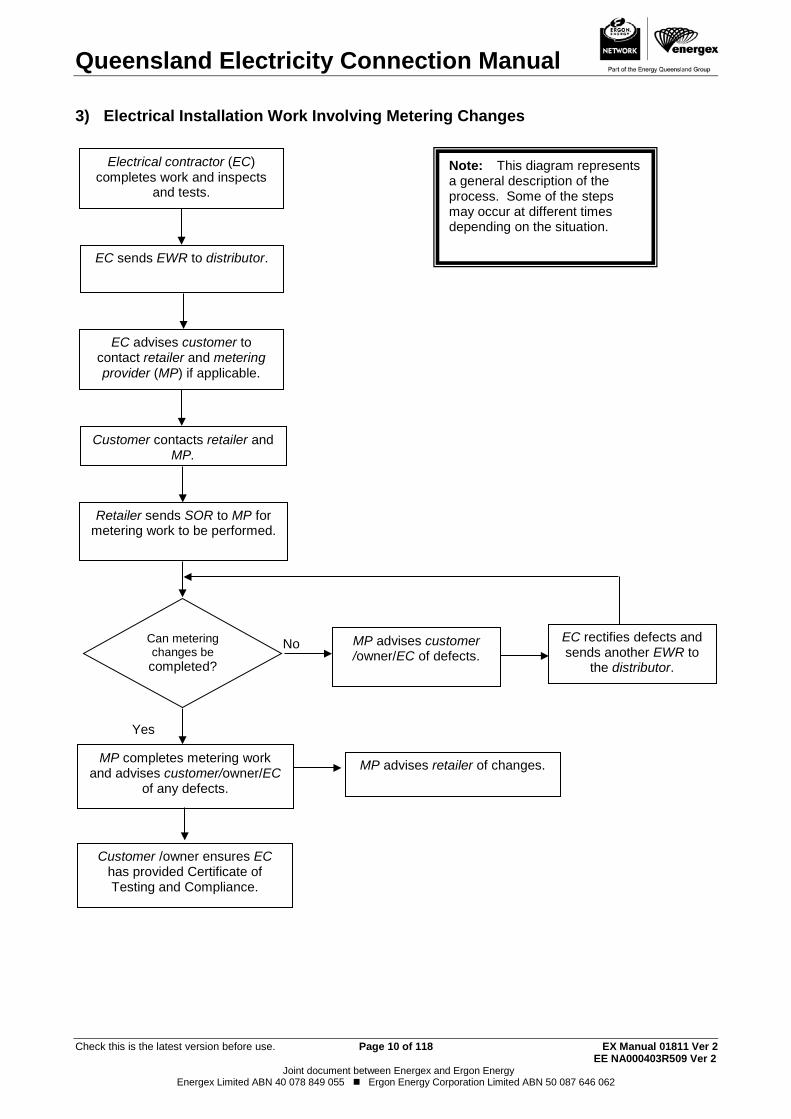
3) Electrical Installation Work Involving Metering Changes
No
Yes
Electrical contractor (EC) completes work and inspects
and tests.
EC sends EWR to distributor.
EC advises customer to contact retailer and metering provider (MP) if applicable.
Customer contacts retailer and MP.
Retailer sends SOR to MP for metering work to be performed.
Can metering changes be completed?
MP advises customer /owner/EC of defects.
EC rectifies defects and sends another EWR to
the distributor.
MP completes metering work and advises customer/owner/EC
of any defects.
MP advises retailer of changes.
Note: This diagram represents a general description of the process. Some of the steps may occur at different times depending on the situation.
Customer /owner ensures EC has provided Certificate of Testing and Compliance.
Queensland Electricity Connection Manual
Check this is the latest version before use. Page 11 of 118 EX Manual 01811 Ver 2 EE NA000403R509 Ver 2
Joint document between Energex and Ergon Energy Energex Limited ABN 40 078 849 055 Ergon Energy Corporation Limited ABN 50 087 646 062
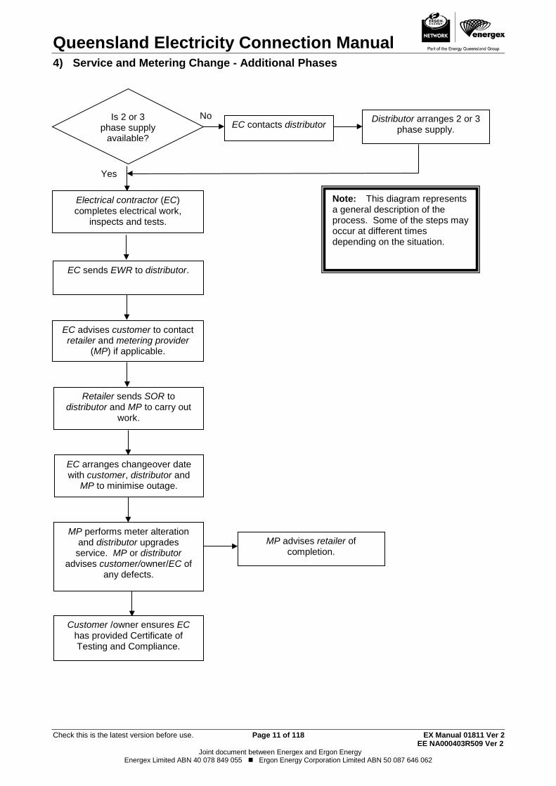
4) Service and Metering Change - Additional Phases
No
Yes
Is 2 or 3 phase supply
available? EC contacts distributor Distributor arranges 2 or 3
phase supply.
Electrical contractor (EC) completes electrical work,
inspects and tests.
EC sends EWR to distributor.
EC advises customer to contact retailer and metering provider
(MP) if applicable.
Retailer sends SOR to distributor and MP to carry out
work.
EC arranges changeover date with customer, distributor and
MP to minimise outage.
MP performs meter alteration and distributor upgrades service. MP or distributor
advises customer/owner/EC of any defects.
MP advises retailer of completion.
Note: This diagram represents a general description of the process. Some of the steps may occur at different times depending on the situation.
Customer /owner ensures EC has provided Certificate of Testing and Compliance.
Queensland Electricity Connection Manual
Check this is the latest version before use. Page 12 of 118 EX Manual 01811 Ver 2 EE NA000403R509 Ver 2
Joint document between Energex and Ergon Energy Energex Limited ABN 40 078 849 055 Ergon Energy Corporation Limited ABN 50 087 646 062
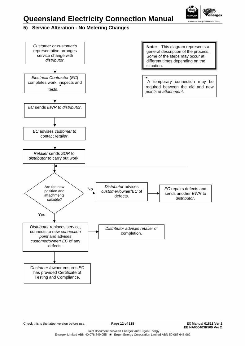
5) Service Alteration - No Metering Changes
No
Yes
Are the new position and attachments
suitable?
Customer or customer’s representative arranges
service change with distributor.
Electrical Contractor (EC) completes work, inspects and
tests. *
*A temporary connection may be
required between the old and new points of attachment.
Distributor advises customer/owner/EC of
defects.
EC repairs defects and sends another EWR to
distributor.
Distributor replaces service, connects to new connection
point and advises customer/owner/ EC of any
defects.
EC advises customer to contact retailer.
Retailer sends SOR to distributor to carry out work.
EC sends EWR to distributor.
Distributor advises retailer of completion.
Note: This diagram represents a general description of the process. Some of the steps may occur at different times depending on the situation.
Customer /owner ensures EC has provided Certificate of Testing and Compliance.
Queensland Electricity Connection Manual
Check this is the latest version before use. Page 13 of 118 EX Manual 01811 Ver 2 EE NA000403R509 Ver 2
Joint document between Energex and Ergon Energy Energex Limited ABN 40 078 849 055 Ergon Energy Corporation Limited ABN 50 087 646 062
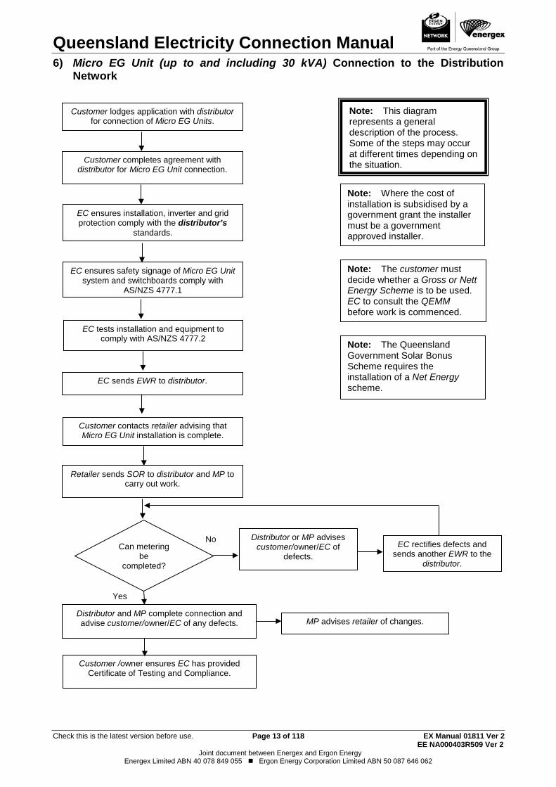
6) Micro EG Unit (up to and including 30 kVA) Connection to the Distribution Network
No
Yes
Customer contacts retailer advising that Micro EG Unit installation is complete.
EC ensures installation, inverter and grid protection comply with the distributor’s
standards.
EC tests installation and equipment to comply with AS/NZS 4777.2
Can metering be
completed?
EC rectifies defects and sends another EWR to the
distributor.
Distributor and MP complete connection and advise customer/owner/EC of any defects.
MP advises retailer of changes.
Note: Where the cost of installation is subsidised by a government grant the installer must be a government approved installer.
Customer lodges application with distributor for connection of Micro EG Units.
EC ensures safety signage of Micro EG Unit system and switchboards comply with
AS/NZS 4777.1
Customer completes agreement with distributor for Micro EG Unit connection.
Retailer sends SOR to distributor and MP to carry out work.
EC sends EWR to distributor.
Distributor or MP advises customer/owner/EC of
defects.
Note: The customer must decide whether a Gross or Nett Energy Scheme is to be used. EC to consult the QEMM before work is commenced.
Note: The Queensland Government Solar Bonus Scheme requires the installation of a Net Energy scheme.
Note: This diagram represents a general description of the process. Some of the steps may occur at different times depending on the situation.
Customer /owner ensures EC has provided Certificate of Testing and Compliance.
Queensland Electricity Connection Manual
Check this is the latest version before use. Page 14 of 118 EX Manual 01811 Ver 2 EE NA000403R509 Ver 2
Joint document between Energex and Ergon Energy Energex Limited ABN 40 078 849 055 Ergon Energy Corporation Limited ABN 50 087 646 062
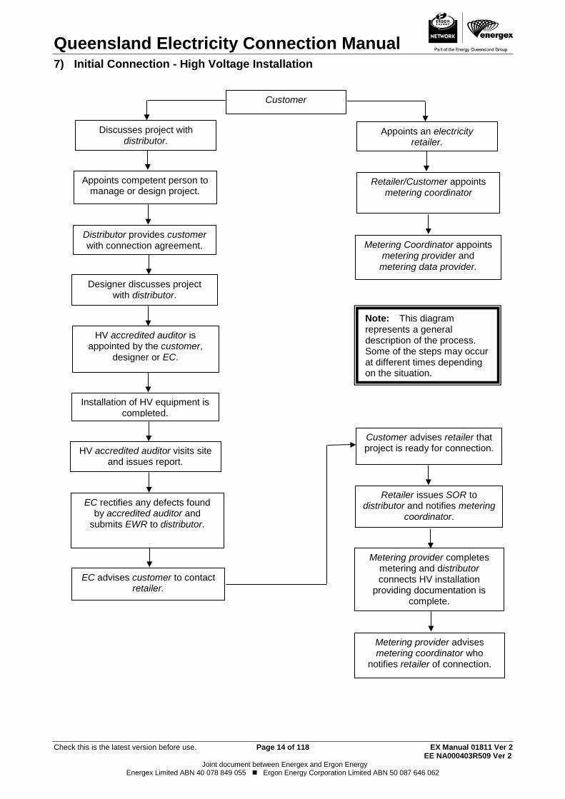
7) Initial Connection - High Voltage Installation
Customer
Discusses project with distributor.
Designer discusses project with distributor.
Installation of HV equipment is completed.
HV accredited auditor visits site and issues report.
EC advises customer to contact retailer.
Metering provider completes metering and distributor connects HV installation
providing documentation is complete.
Appoints competent person to manage or design project.
Appoints an electricity retailer.
Retailer/Customer appoints metering coordinator
Distributor provides customer with connection agreement.
Customer advises retailer that project is ready for connection.
HV accredited auditor is appointed by the customer,
designer or EC.
Retailer issues SOR to distributor and notifies metering
coordinator. EC rectifies any defects found
by accredited auditor and submits EWR to distributor.
Metering provider advises metering coordinator who
notifies retailer of connection.
Note: This diagram represents a general description of the process. Some of the steps may occur at different times depending on the situation.
Metering Coordinator appoints metering provider and metering data provider.

Queensland Electricity Connection Manual
Check this is the latest version before use. Page 15 of 118 EX Manual 01811 Ver 2 EE NA000403R509 Ver 2
Joint document between Energex and Ergon Energy Energex Limited ABN 40 078 849 055 Ergon Energy Corporation Limited ABN 50 087 646 062
THIS PAGE HAS BEEN DELIBERATELY LEFT BLANK
Queensland Electricity Connection Manual
Check this is the latest version before use. Page 16 of 118 EX Manual 01811 Ver 2 EE NA000403R509 Ver 2
Joint document between Energex and Ergon Energy Energex Limited ABN 40 078 849 055 Ergon Energy Corporation Limited ABN 50 087 646 062
1. IMPORTANT INFORMATION Use of this document 1.1.
This document is to be read in conjunction with the current:
(a) Australian Standards, in particular AS/NZS 3000 (Wiring Rules).
(b) Relevant Legislation and respective Regulations and Codes (see References pg 5).
(c) The National Electricity Rules.
(d) QECM addendums published in relation to specific topics (on and from the date they are published).
(e) Queenland Electricity Metering Manual (QEMM)
Note: The requirements of the Queensland Electricity Legislation are to be considered in the design, installation, operation and maintenance of the customer’s electrical installation
This is a self-contained document except where it specifically refers to other related documents and supersedes previous versions of both the Energex and Ergon Energy Electricity Connection and Metering Manuals.
Scope 1.2.This document provides guidelines for connection of supply, metering and load control arrangements of a customer's installation.
Where departures from these guidelines may be necessary, prior consultation with the distributor will be required. (Refer to Clause 1.4, Exceptional Circumstances).
Note: If there is any inconsistency between the guidelines provided in the QECM and -
(a) the relevant legislation (i.e. the Electricity Act 1994, the Electrical Safety Act 2002 and their respective Regulations or Codes of Practice), AS/NZS 3000 (Wiring Rules) and the National Electricity Rules, or
(b) the terms contained in a distributor’s letter of offer to supply, or a connection agreement;
then the relevant legislation set out above at clause 1.2 (a), shall prevail in the first instance, followed by Clause 1.2 (b), the terms of a letter of offer to supply or a connection agreement.
Small Customers 1.2.1
The conditions of supply and metering requirements detailed in this document apply for all customers who consume less than 100MWh per annum (i.e. a Small Customer) and are connected to the distributor’s electricity network.
Large Market Customers 1.2.2
The conditions of supply and metering for customers who are Registered Participants according to National Electricity Rules, consume 100MWh or more annually and have an Electricity Sales Contract with a retailer are detailed in the National Electricity Rules Chapter 5 - Network Connection.
Where specific detail is not covered by the National Electricity Rules the requirements of this document apply. Connections for new large customers must comply with the Queensland Electricity Regulation 2006.
Un-metered Supplies 1.2.3
The conditions of supply for customers whose connection point is not metered, and are connected to the distribution network, are detailed in this document.
Queensland Electricity Connection Manual
Check this is the latest version before use. Page 17 of 118 EX Manual 01811 Ver 2 EE NA000403R509 Ver 2
Joint document between Energex and Ergon Energy Energex Limited ABN 40 078 849 055 Ergon Energy Corporation Limited ABN 50 087 646 062
Remote Generated Areas 1.2.4
The conditions of supply and metering requirements detailed in this document apply to all customers’ installations and are to be read in conjunction with Ergon Energy document PW000202R114 - "Guidelines for Electrical Installations at Isolated Systems." Call Customer Service (refer page 1).
Failure to comply with this manual 1.3.Should an installation not satisfy the requirements of these and/or other applicable rules, the connection of electricity supply may be delayed or withheld, and installations with supply may be disconnected, until such time as the non-compliance(s) has been rectified.
Exceptional Circumstances 1.4.In exceptional circumstances the stated requirements contained within the QECM may be waived and/or modified by the submission of a written request to the relevant distributor. (Refer to Clause 1.6 for contact details).
The request shall include all of the following:
(a) A detailed statement of the reasons why non-compliance with this manual is sought.
(b) Full details and diagrams, as necessary, showing the specific aspect of a requested variation to the QECM.
(c) Property location details.
No action or variation should be undertaken until a written approval from the distributor, has been received.
Note: Any variation approval will only apply to the individual property as listed in the request (i.e. it does not cover, or set any precedent, for any other installation).
Request for an interpretation of the QECM 1.4.1
A request for an interpretation of the QECM must be made in writing to the relevant distributor. A reply will be provided by the distributor within 10 working days from receipt of the written request.
Request for dispensation from the QECM 1.4.2
A request for dispensation from the requirements of the QECM must be made in writing to the relevant distributor. A reply will be provided within 10 working days from receipt of the written request.
Request for an QECM amendment 1.4.3
A request for an amendment of the QECM must be made in writing to the relevant distributor. Acknowledgement of receipt of the amendment will be provided within 10 working days from receipt of the written request.
Enquiries 1.5.Unless indicated, enquiries are to be by email or by written communication.
Enquiries before the work commences or whilethe work is underway. 1.5.1
Contact the phone numbers on page 1 of the QECM.
Enquiries regarding defects identified by the distributor 1.5.2
Contact the distributor advising the following information:
Queensland Electricity Connection Manual
Check this is the latest version before use. Page 18 of 118 EX Manual 01811 Ver 2 EE NA000403R509 Ver 2
Joint document between Energex and Ergon Energy Energex Limited ABN 40 078 849 055 Ergon Energy Corporation Limited ABN 50 087 646 062
(a) Customer name and address and NMI if available;
(b) Reference number on the distributor’s document;
(c) Nature of enquiry;
(d) Electrical contractor’s number and return address details (if applicable).
If the installation has not been connected to supply a reply will be provided within 2 working days from receipt of request.
If the installation has been connected to supply a reply will be provided within 5 working days from receipt of request. (Refer to Clause 1.6 for contact details).
Distributors Contact Details for QECM Correspondence 1.6.Contact details for QECM amendments or enquiries are:
Energex: Email [email protected]
Write to: Energex Limited QECM Request
GPO Box 1461
BRISBANE Qld 4001
Ergon Energy: Email: [email protected]
Write to: Ergon Energy QECM Request
PO Box 308
ROCKHAMPTON Qld 4700 Historic Buildings and Flora with Vegetation Protection Orders 1.7.
The electrical contractor should consult the owner if the building appears to have historical significance. Historic buildings may require the requirements of this manual be waived and/or modified for attachment of overhead services, meter positions etc.
Similarly, flora protected by a Vegetation Protection Order may require special arrangements for the erection or alteration of overhead or underground services.
Electrical contractors should contact the distributor before starting work (See Exceptional Circumstances above).
Revisions and alterations 1.8.Energex and Ergon Energy reserve the right to revise this publication. The current edition of this document is available on the Energex website at www.energex.com.au or the Ergon Energy website at www.ergon.com.au.
Drawings 1.9.The drawings have been placed in the body of the document after the section to which they are most relevant but may be referred to in more than one section.
Queensland Electricity Connection Manual
Check this is the latest version before use. Page 19 of 118 EX Manual 01811 Ver 2 EE NA000403R509 Ver 2
Joint document between Energex and Ergon Energy Energex Limited ABN 40 078 849 055 Ergon Energy Corporation Limited ABN 50 087 646 062
THIS PAGE HAS BEEN DELIBERATELY LEFT BLANK

Queensland Electricity Connection Manual
Check this is the latest version before use. Page 20 of 118 EX Manual 01811 Ver 2 EE NA000403R509 Ver 2
Joint document between Energex and Ergon Energy Energex Limited ABN 40 078 849 055 Ergon Energy Corporation Limited ABN 50 087 646 062
2. CUSTOMERS INSTALLATIONS Request for Electrical Connection 2.1.
An application for supply must be made to an electricity retailer licensed to operate in Queensland.
The distributor cannot energise a customer’s installation unless:
(a) The customer has a retail sales contract; and
(b) The retailer has then requested the distributor to connect the customer via a SOR transaction; and
(c) An Electrical Work Request (EWR) has been submitted.
Where possible, and to hasten completion, the customer should provide the National Metering Identifier to the retailer.
Large Customers 2.1.1
A large customer who consumes 100MWh or more per annum and requires an initial connection by the distributor must also arrange for the metering to be installed by an accredited metering provider. They must also request their initial connection via their chosen retailer.
To enable the connection to be completed to schedule, a customer will be required to advise the distributor of their expected annual consumption.
Request for Initial Connection, Service Alteration, Metering Change or Inverter 2.2.change
Electrical Contractors shall submit an Electrical Work Request (EWR) when they:
(a) Require an initial supply at an installation; or
(b) Require service alterations.
Where alterations to an installation are to be carried out, the distributor shall be advised of any of the following situations:
(a) Where the electricity service may be over or in the vicinity of a swimming pool or hazardous area as defined in AS/NZS 3000 (Wiring Rules);
(b) Any proposal for new or additions to an existing HV installation (i.e. the connection point and or the metering transformer may need upgrading).
For major changes or load increases the customer, or their electrical contractor or consultant, should contact the distributor at the earliest opportunity to obtain an estimate of the time that may be required to modify the network to accommodate the changes or load increases; or
(c) Complete work that requires additional metering or a change to existing metering when the distributor is the metering provider; or
(d) Complete work that requires additional load control equipment or a change to existing load control equipment; or
(e) Require Micro EG unit Inverter additions, upgrades or replacement.
Queensland Electricity Connection Manual
Check this is the latest version before use. Page 21 of 118 EX Manual 01811 Ver 2 EE NA000403R509 Ver 2
Joint document between Energex and Ergon Energy Energex Limited ABN 40 078 849 055 Ergon Energy Corporation Limited ABN 50 087 646 062
Alterations and Additions 2.3.The electrical contractor shall submit an Electrical Work Request (EWR) in adequate time for the modification to the distributor’s service and or network to be completed before supply is required.
Examples of alterations and/or additions to the customer electrical installation that require submission of an EWR may include:
(a) The installation of additional phase/s;
(b) The relocation of the connection point;
(c) Any increase in loading that requires an increase in the capacity of the service or distribution network;
(d) The installation of a service following repair works (e.g. repair works after storm damage).
Note: Customers with a NMI classification - Large, are to provide the contact details of their metering provider.
Breaking of Metering Terminal Cover/Metering Isolation Link/Metering Neutral 2.4.Link Seals
In the interests of electrical safety and to ensure the integrity of metering and network devices the metering provider and/or the distributor will seal this equipment.
Approval will be given for the metering terminal cover/metering isolation link/metering neutral link seals only, to be removed by an electrical contractor provided notification is given to the distributor or the metering provider either before the removal of the seals or as soon as practicable after the event.
An Electrical Work Request (EWR) must be submitted to the distributor as soon as possible after metering alterations are completed.
Where the metering terminal cover has been damaged or alterations to the metering cable entry point allows contact with live parts, the electrical contractor shall leave the installation in a safe state (e.g. fill/cover holes with a suitable material) and submit an EWR that advises a new metering terminal cover is required. Alterations to metering terminal covers are not permitted.
Note: For remotely read interval meter installations, the customer is to provide the contact details of their metering provider. The nominated metering provider is responsible to ensure the metering installation complies with the requirements of Chapter 7, of the National Electricity Rules and this document where applicable.
Within the Ergon Energy distribution area, notification of broken seals (for Receiver bridging only) can be done via a phone call to the National Contact Centre.
Within the Ergon Energy distribution area, an EWR (Form A) must be submitted when there is an upgrade or replacement of an existing micro EG unit inverter, or when an inverter is added to an existing inverter. A new meter will not be required but normal system compliance checking is still required. A new application must be lodged for any inverter change or addition within both the Ergon Energy and Energex distribution areas and also for solar panel changes within the Ergon Energy distribution area. (Refer to Clause 8.2).
Queensland Electricity Connection Manual
Check this is the latest version before use. Page 22 of 118 EX Manual 01811 Ver 2 EE NA000403R509 Ver 2
Joint document between Energex and Ergon Energy Energex Limited ABN 40 078 849 055 Ergon Energy Corporation Limited ABN 50 087 646 062
Examination, Test and Connection 2.5.The distributor’s electricity connection officer is required to examine and test the consumer’s mains and main switchboard of an installation before the initial connection to supply (up to the load side of the Metering Isolation Link and Metering Neutral Link). The examination, test, and connection shall not be regarded as implying compliance with any specification and the electrical contractor remains responsible for the standard of the work, regardless of whether an officer from the distributor examines, or tests, the whole or part of the installation.
The re-energisation of an installation after customer requested switching shall not be regarded as implying compliance with any specification and the electrical contractor remains responsible for the standard of the work, regardless of whether an officer from the distributor examines, or tests, the whole or part of the installation.
Unmetered Supplies 2.6.Unmetered supply may be available where the distributor considers it impractical to read or maintain metering equipment or where metering equipment would be susceptible to damage. Approval must be obtained from the distributor prior to the installation of an unmetered supply. Where the distributor consents to an unmetered supply (e.g. telephone cabinet, bus shelter, traffic signals, etc.) the following general conditions will apply:
(a) Approval must be gained (as appropriate) from any relevant authority for equipment installed in the road reserve. (Refer to the Electricity Regulation 2006);
(b) The distributor must be advised prior to any changes to the loading of the installation;
(c) Socket outlets are not permitted;
(d) The installation shall consist of a small steady uniform load. (Refer to Clause 5.9(a) for installation of consumer’s mains on the distributor’s pole).
Identification in Multiple Installations 2.7.Each individually metered section of a multiple installation shall be clearly identifiable (e.g. shop, unit or factory number). The number shall be permanently marked on the main switchboard, distribution board (if applicable), meter, isolator and front door of the individual shop/unit so that the distributor may install the required connection for the installation. A site plan of the overall layout of the site shall also be permanently displayed on the inside door of the main switchboard.
An electrical test must be carried out to ensure that the meter wiring does supply that particular part of the installation that is identified by the switchboard and unit marking. This is required to confirm the relationship between the national metering identifier (NMI), the meter number/s and the address are correct.
Protective Fault Current Devices 2.8.Protective devices installed by the customer shall have an interrupting capacity adequate for the prospective short circuit current at the point of installation.
In the event of the fault current being increased at any point on an installation because of provisions for additional load, the customer shall be responsible for the upgrading of all equipment not rated for the prospective fault level.
Prospective fault level details may be obtained by contacting the distributor. (Refer to page 1 for contact details).
Notes: 1. The distributor’s (HRC) low voltage service fuse rated up to 100A will provide suitable
fault current limiting for a customer’s installation. Refer to QEMM for additional meter protection requirements.
Queensland Electricity Connection Manual
Check this is the latest version before use. Page 23 of 118 EX Manual 01811 Ver 2 EE NA000403R509 Ver 2
Joint document between Energex and Ergon Energy Energex Limited ABN 40 078 849 055 Ergon Energy Corporation Limited ABN 50 087 646 062
2. For low voltage supplies the distributor’s service fuse shall not be considered as overload protection for the consumer’s mains.
3. Installation of fault current limiters may be required to protect direct connected metering on the customer’s installation. (Refer to Clause 6.3.1).
Information on high fault currents can be found in the Electrical Safety Office - Code of Practice for Electrical Work and the Electrical Safety Office web site.
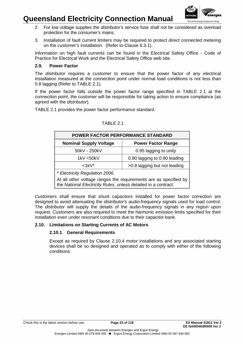
Power Factor 2.9.The distributor requires a customer to ensure that the power factor of any electrical installation measured at the connection point under normal load conditions is not less than 0.8 lagging (Refer to TABLE 2.1).
If the power factor falls outside the power factor range specified in TABLE 2.1 at the connection point, the customer will be responsible for taking action to ensure compliance (as agreed with the distributor).
TABLE 2.1 provides the power factor performance standard.
TABLE 2.1
POWER FACTOR PERFORMANCE STANDARD Nominal Supply Voltage Power Factor Range
50kV - 250kV 0.95 lagging to unity 1kV <50kV 0.90 lagging to 0.90 leading
<1kV* >0.8 lagging but not leading * Electricity Regulation 2006. At all other voltage ranges the requirements are as specified by the National Electricity Rules, unless detailed in a contract.
Customers shall ensure that shunt capacitors installed for power factor correction are designed to avoid attenuating the distributor’s audio-frequency signals used for load control. The distributor will supply the details of the audio-frequency signals in any region upon request. Customers are also required to meet the harmonic emission limits specified for their installation even under resonant conditions due to their capacitor bank.
Limitations on Starting Currents of AC Motors 2.10. General Requirements 2.10.1
Except as required by Clause 2.10.4 motor installations and any associated starting devices shall be so designed and operated as to comply with either of the following conditions:
Queensland Electricity Connection Manual
Check this is the latest version before use. Page 24 of 118 EX Manual 01811 Ver 2 EE NA000403R509 Ver 2
Joint document between Energex and Ergon Energy Energex Limited ABN 40 078 849 055 Ergon Energy Corporation Limited ABN 50 087 646 062
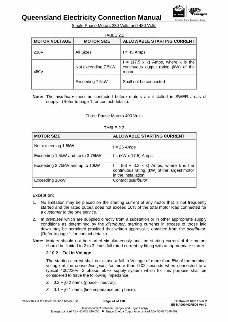
Single Phase Motors 230 Volts and 480 Volts
TABLE 2.2 MOTOR VOLTAGE MOTOR SIZE ALLOWABLE STARTING CURRENT 230V
All Sizes
I = 45 Amps
480V
Not exceeding 7.5kW
I = (17.5 x k) Amps, where k is the continuous output rating (kW) of the motor.
Exceeding 7.5kW
Shall not be connected.
Note: The distributor must be contacted before motors are installed in SWER areas of
supply. (Refer to page 1 for contact details).
Three Phase Motors 400 Volts
TABLE 2.3
MOTOR SIZE ALLOWABLE STARTING CURRENT Not exceeding 1.5kW
I = 26 Amps
Exceeding 1.5kW and up to 3.75kW
I = (kW x 17.5) Amps
Exceeding 3.75kW and up to 10kW
I = (53 + 3.3 x k) Amps, where k is the continuous rating, (kW) of the largest motor in the installation.
Exceeding 10kW
Contact distributor.
Exception: 1. No limitation may be placed on the starting current of any motor that is not frequently
started and the rated output does not exceed 10% of the total motor load connected for a customer to the one service.
2. In premises which are supplied directly from a substation or in other appropriate supply conditions as determined by the distributor, starting currents in excess of those laid down may be permitted provided that written approval is obtained from the distributor. (Refer to page 1 for contact details).
Note: Motors should not be started simultaneously and the starting current of the motors should be limited to 2 to 3 times full rated current by fitting with an appropriate starter.
Fall in Voltage 2.10.2
The starting current shall not cause a fall in Voltage of more than 5% of the nominal voltage at the connection point for more than 0.02 seconds when connected to a typical 400/230V, 3 phase, 50Hz supply system which for this purpose shall be considered to have the following impedance:
Z = 0.2 + j0.2 ohms (phase - neutral);
Z = 0.1 + j0.1 ohms (line impedance per phase).
Queensland Electricity Connection Manual
Check this is the latest version before use. Page 25 of 118 EX Manual 01811 Ver 2 EE NA000403R509 Ver 2
Joint document between Energex and Ergon Energy Energex Limited ABN 40 078 849 055 Ergon Energy Corporation Limited ABN 50 087 646 062
Test Methods 2.10.3
(a) Fall in Voltage shall be measured by instrumentation with a high-speed measurement capability.
(b) Starting currents shall be measured by instrumentation with a high-speed measurement capability or by the locked rotor method, with the rated voltage and frequency applied to the terminals of the motor.
(c) In any case where the test methods specified in paragraphs (a) and (b) above cannot conveniently be applied, another test method that conforms to recognised practices in the electrical industry may be used.
Note: The distributor will accept test results from a recognised testing laboratory or manufacturer's certified test results.
Special Provisions 2.10.4
For both three phase and single phase motors the distributor may require maximum starting currents lower than those set out or may limit the rating of any motor to be connected if such lower starting currents or limits of motor capacity are necessary to prevent interference with supply to other customers.
For isolated generation areas within the Ergon Energy distribution area, special limitations may be applied on starting currents of electric motors (including air conditioners) and also may require time delay controls on motor starting circuits after a power outage. Any special requirements are outlined in the Ergon Energy document PW000202R114 - "Guidelines for Electrical Installations at Isolated Systems" which is available on request by contacting Ergon Energy Customer Service. (Refer to page 1 for contact details).
Interference with Supply of Electricity to Other Customers 2.11.Customers shall take reasonable precautions to prevent transformer arc welding machines, motor starting, fluorescent lighting, Micro Embedded Generation and any other equipment from interfering with the satisfactory operation of the distributor’s network or other customers systems etc.
The requirements of AS/NZS 61000 series standards "Electromagnetic Compatibility (EMC)" shall be observed at all times.
The fact that the distributor may have connected the apparatus or equipment causing the interference shall not exempt the customer from this requirement. Also see Clauses 4.2 to 4.6 of this manual.
Note: Customers with an electrical installation or equipment which may be sensitive to voltage variation, transients, loss of one or more phases of supply or due to leakage current are advised to install protective equipment to limit possible damage.
High Voltage Installations 2.12.Any person intending to install high voltage equipment at a premise shall consult the distributor before taking steps to obtain or install such equipment.
Where the distributor agrees, subject to certain conditions, (such as a minimum demand being met), with a customer’s request for a high voltage connection, the agreed voltage is the standard voltage for the supply. (Refer to the Electricity Regulation 2006 for standard voltages). The distributor will provide a letter of offer or connection agreement outlining these conditions.
The Electrical Safety Act 2002 requires all new or altered high voltage electrical installations to be inspected by an Accredited Auditor before connection to supply. For additional information on Accredited Auditors contact the Electrical Safety Office. The auditor should be involved in the project at an early stage.
Queensland Electricity Connection Manual
Check this is the latest version before use. Page 26 of 118 EX Manual 01811 Ver 2 EE NA000403R509 Ver 2
Joint document between Energex and Ergon Energy Energex Limited ABN 40 078 849 055 Ergon Energy Corporation Limited ABN 50 087 646 062
More information in relation to high voltage installations is included in Chapter 9 of this manual
Customer's Generating Systems 2.13. General 2.13.1
The installation of customer’s generating systems shall comply with AS/NZS 3000 (Wiring Rules). The consumer’s mains neutral shall not be switched or broken on the distribution supply side of the MEN connection. The generating system neutral is required to be clearly identified at the main neutral link.
Non-Parallel Operation with Distributors Supply 2.13.2
Customer's generating system for emergency supply
This section applies for the installation of generating system on a customer’s premises to provide a supply of electricity to the customer’s electrical installation, during an interruption of the supply of electricity.
(a) The customer shall ensure that, when the generating system is operating to give emergency supply, it is installed with effective isolation between― (i) all active conductors of the part of the electrical installation or electrical
installations to which the generating system is connected; and (ii) the part of the electrical installation still connected to the supply from the
distributor.
(b) The connection of the generating system shall be so arranged that the metering provider’s revenue meters do not meter the alternate supply and all metering equipment, including CTs are able to be isolated to enable access whilst the generating system is in service (i.e. the changeover switch must be installed on the load side of the meter).
Parallel Operation with Distributor’s Supply (Co-Generation) 2.13.3
Customer's generating system for interconnection to supply network
(a) A customer shall not install generating plant for interconnection with the distributor’s supply network without prior agreement.
(b) The agreement shall include the conditions for securing safe and stable parallel operation of the supply network and the generating system.(refer to section 28 of the Electricity Regulation 2006).
Note: Co-generation is allowable from all forms of alternative energy supplies such as solar panel (photovoltaic), wind turbine, diesel generation etc.
Refer to Section 8 for details of the metering schemes for interconnection of EG systems connected to the distribution network.
Appropriate revenue metering will be installed in accordance with the negotiated supply arrangements.
Determination of Maximum Demand 2.14.Unless limited by a fixed setting circuit breaker, the determination of the maximum demand of an installation shall be calculated, measured or assessed in accordance with the guidelines given in AS/NZS 3000 (Wiring Rules).
Requirement for Circuit Breakers in Rural/Isolated Areas 2.15.The distributor requires circuit breaker/s for main switch/s as part of the customer’s installation and these circuit breaker/s are required to coordinate with the service fuse/circuit breaker. The distributor may require the customer's protective device to be changed or altered to provide adequate discrimination. Electricity Regulation 2006, sections 29 and 30.
Queensland Electricity Connection Manual
Check this is the latest version before use. Page 27 of 118 EX Manual 01811 Ver 2 EE NA000403R509 Ver 2
Joint document between Energex and Ergon Energy Energex Limited ABN 40 078 849 055 Ergon Energy Corporation Limited ABN 50 087 646 062
Notes: 1. These regulations refer to the customer owned circuit breaker main switch/s provided as
part of the customer's installation and not to the customer's sub-circuit protection or the distributor’s service fuse/circuit breaker.
2. Refer to Glossary of Terms for definition of rural/isolated area.
Queensland Electricity Connection Manual
Check this is the latest version before use. Page 28 of 118 EX Manual 01811 Ver 2 EE NA000403R509 Ver 2
Joint document between Energex and Ergon Energy Energex Limited ABN 40 078 849 055 Ergon Energy Corporation Limited ABN 50 087 646 062
3. DETERMINATION OF THE NUMBER OF PHASES TO BE INSTALLED General 3.1.
The number of phases provided to supply load at an installation shall be the number required by Section 4 of this manual for individual apparatus or the number determined by this section, whichever is the greater.
Note: The electrical contractor or designer should consult with the customer to determine future loading requirements. Provision for additional phases or larger consumer’s mains may be required (e.g. air conditioning load, Micro EG Unit, EVSE).
Urban Areas 3.2. Single Customer Installations 3.2.1
Other than where multi-phase appliances are installed on the premises, if the maximum demand as calculated in accordance with AS/NZS 3000 (Wiring Rules) is:
(a) not greater than 80A, then supply shall be one phase and neutral;
(b) between 80 and 140A, then supply shall be two phases and neutral;
(c) greater than 140A, then supply shall be three phases and neutral.
The distributor approves the use of 3 phase underground or overhead supply where 3 phase load (e.g. air conditioner or pump) is connected and the remainder of the installation is balanced across the 3 phases.
Multi Customer Installations 3.2.2
Other than where multi-phase appliances are installed on the premises the number of phases shall be determined by the following methods:
(a) A maximum of two individually metered units may be connected to a single phase supply if the maximum demand calculated in accordance with AS/NZS 3000 (Wiring Rules) does not exceed 70A.
(b) Where there are more than two individually metered units, the installation shall be arranged for a three phase supply (e.g. three units - one per phase) unless otherwise advised by the distributor.
Note: Separate services and meter positions shall be installed for a duplex (two units divided by a common wall) where each portion has a separate (freehold) title. (Refer also to Clause 6.6.3.5 for Community Title Scheme arrangements).
Non-Urban Areas 3.3.In non-urban areas connection of additional phases to the customer’s electrical installation may be necessary even though not required under the guidelines given in Clause 3.2.
Notes: 1. Where single phase 11kV only is available the maximum demand may be increased up to
100A depending on the capacity of the local transformer and supporting high voltage infrastructure.
2. Load limitations may apply for single wire earth return (SWER) systems.
For electrical installations in these areas electrical contractors should consult the distributor. (Refer to page 1 for contact details).

Queensland Electricity Connection Manual
Check this is the latest version before use. Page 29 of 118 EX Manual 01811 Ver 2 EE NA000403R509 Ver 2
Joint document between Energex and Ergon Energy Energex Limited ABN 40 078 849 055 Ergon Energy Corporation Limited ABN 50 087 646 062
THIS PAGE HAS BEEN DELIBERATELY LEFT BLANK
Queensland Electricity Connection Manual
Check this is the latest version before use. Page 30 of 118 EX Manual 01811 Ver 2 EE NA000403R509 Ver 2
Joint document between Energex and Ergon Energy Energex Limited ABN 40 078 849 055 Ergon Energy Corporation Limited ABN 50 087 646 062
4. BALANCING OF LOAD AND LIMITATION ON EQUIPMENT General 4.1.
The load of an installation (including all primary and secondary tariff loads), or separately metered portion of an installation supplied by separate consumer’s mains or submains, shall be so balanced that at the time of maximum demand on such installation or portion of such installation the current in any phase does not exceed the current in any other phase by more than 20A or 20% whichever is the greater (unless otherwise approved in writing by the distributor). The principal tariff load (and secondary tariff load where possible) shall be balanced across all supplied phases and the use of controlled or time of use tariffs to balance another tariff across phases will not be accepted.
The distributor may apply additional conditions when large loads are connected in rural (non-urban) areas.
Connection of Equipment - Current Limitations 4.2.Equipment (not specified elsewhere in this part, or a lighting installation or a sign) designed to operate at 230V and whose rating is:
(a) Not greater than 25A will be connected between one phase and neutral.
(i) In exceptional circumstances the distributor may approve the connection of single phase appliances rated at more than 25A; and
(ii) In multiphase electrical installations the equipment may, with the approval of the distributor, be connected to more than one phase and neutral provided the load of the installation is to be balanced across the supply phases.
(b) Greater than 25A, but not greater than 50A, shall be connected between two phases and neutral, except that in multiphase electrical installations the equipment may, with the approval of the distributor be connected to more than two phases and neutral.
(c) Greater than 50A, shall be connected to three phases and neutral.
Domestic Ranges 4.2.1
Urban Areas
Where an individually metered installation includes a cooking range or ranges, a total rating not exceeding 13kW may be connected to one phase and neutral.
If the total rating exceeds 13kW then:
(a) For one range it shall be connected to at least two phases and neutral; or
(b) For two or more ranges each range may be connected to one phase and neutral of a multiphase supply.
Non-Urban Areas
Where in accordance with Clause 3.2 an electrical installation is required to be connected to either two phase and neutral, or three phase and neutral, all ranges should be balanced over the number of phases connected.
Commercial Cooking Appliances 4.2.2
Any such appliance, whose total rating at 230V is:
(a) Not greater than 35A, shall be connected to one phase and neutral; or
(b) Greater than 35A, shall be connected to a minimum of two phases and neutral.
Queensland Electricity Connection Manual
Check this is the latest version before use. Page 31 of 118 EX Manual 01811 Ver 2 EE NA000403R509 Ver 2
Joint document between Energex and Ergon Energy Energex Limited ABN 40 078 849 055 Ergon Energy Corporation Limited ABN 50 087 646 062
Water Heaters 4.2.3
(a) Instantaneous water heater systems
I. Residential
The rated current of an instantaneous water heater shall not exceed 40A (total load) for a three phase system or 20A for a single phase system in a residential building, unless otherwise approved in writing by the distributor.
II. Commercial/Industrial
The rated current of an instantaneous water heater shall not exceed 40A (total load) for a three phase system or 40A for a single phase system (Energex only) or 20A for a single phase system (Ergon Energy only) in a commercial or industrial building, unless otherwise approved in writing by the distributor.
(b) For the suitability of water heaters for controlled or night rate supplies reference should be made to the Network Tariff Guide (available from the distributor’s web site) e.g. where the heating unit rating exceeds 1800W, it shall not exceed 13.5W per litre of heat storage volume for heat exchange type water heaters or 15.5W per litre of rated hot water delivery for other storage type water heaters.
Kilns in Domestic Installations 4.2.4
A kiln, which has a total rating not exceeding 30A, shall be connected to one phase and neutral in domestic installations.
A kiln with a total rating exceeding 30A shall be connected to two or more phases and balanced over the number of phases connected to the installation.
Electric Vehicle Supply Equipment 4.2.5
Electric vehicle supply equipment shall be compliant with AS/IEC 62196.
I. Residential
The rated current of the EVSE shall not exceed 40A (total load) for a three phase system or 20A for a single phase system in a residential building, unless otherwise approved in writing by the distributor.
II. Commercial/Industrial
The rated current of the EVSE shall not exceed 40A (total load) for a three phase system or 40A for a single phase system (Energex only) or 20A for a single phase system (Ergon Energy only) in a commercial or industrial building, unless otherwise approved in writing by the distributor.
Equipment Having Fluctuating Loads. 4.3.Examples of equipment having fluctuating loads are: Welding Machines, X-Ray equipment, furnaces etc.
The distributor reserves the right to specify the conditions under which an electricity supply will be given for equipment having rapidly fluctuating loads such as welding machines (other than welding machines complying with AS 60974.6, or previous standards superseded by this standard, and marked "Limited Input"), X-ray equipment and furnaces.
No work should be carried out by a customer until advice has been received on the terms on which supply will be given. (Refer to Clause 2.11 "Interference with Supply of Electricity to Other Customers").
Harmonic Interference or Wave Form Distortion 4.4.The distributor reserves the right to specify the conditions under which an electricity supply will be given for equipment which would cause excessive distortion to the wave form of the
Queensland Electricity Connection Manual
Check this is the latest version before use. Page 32 of 118 EX Manual 01811 Ver 2 EE NA000403R509 Ver 2
Joint document between Energex and Ergon Energy Energex Limited ABN 40 078 849 055 Ergon Energy Corporation Limited ABN 50 087 646 062
supply system voltage. (e.g. rectifiers, frequency converters, load control devices using thyristors or saturable reactors).
Rectifiers 4.5.Alternating to direct current rectifying equipment shall not be connected to the distributor’s system unless:
(a) The rectifier is of the full-wave type; or
(b) A double-wound transformer is interposed between the rectifier and the supply system; or
(c) The rectifier is used in conjunction with an electrical measuring instrument or in similar applications where the rectified current does not exceed 100mA.
Note: Further information regarding general limits may be obtained from AS/NZS 61000 series "Electromagnetic Compatibility (EMC)".
Additional limits apply to avoid harmonic interference to the distributor’s audio frequency load control system. (Refer to Clause 2.9 of this manual).
Connection of Equipment - Voltage Limitations 4.6.All equipment must be able to operate satisfactorily within the voltage limits detailed in the current Queensland Electricity Legislation.
Connection of Equipment - Isolated Generation Localities 4.7.Load restrictions on electric motors, welders, air conditioners and other electrical equipment in excess of 2.4kW may apply in isolated remote generation areas throughout Ergon Energy. Call Customer Service (refer page 1) to clarify any restrictions contained in Ergon Energy document PW000202R114 - "Guidelines for Electrical Installations at Isolated Systems".

Queensland Electricity Connection Manual
Check this is the latest version before use. Page 33 of 118 EX Manual 01811 Ver 2 EE NA000403R509 Ver 2
Joint document between Energex and Ergon Energy Energex Limited ABN 40 078 849 055 Ergon Energy Corporation Limited ABN 50 087 646 062
THIS PAGE HAS BEEN DELIBERATELY LEFT BLANK
Queensland Electricity Connection Manual
Check this is the latest version before use. Page 34 of 118 EX Manual 01811 Ver 2 EE NA000403R509 Ver 2
Joint document between Energex and Ergon Energy Energex Limited ABN 40 078 849 055 Ergon Energy Corporation Limited ABN 50 087 646 062
5. SERVICE LINES AND CONNECTION POINT General 5.1.
Each individual electrical installation (as defined in AS/NZS 3000 (Wiring Rules)) shall have a separate and individual connection to the supply network (i.e. Separate connection point - service line, point of attachment, consumer’s mains etc).
Note: The distributor will not accept any “Joint Use” arrangements where two or more customers share the same property pole and/or property line and/or overhead service (e.g. small lot subdivisions).
Connection point 5.2.Unless otherwise determined or approved by the distributor, the connection point shall be located as detailed in Clauses 5.2.1 and 5.2.2.
Low Voltage 5.2.1
The connection point shall be located -
(a) at the termination of the overhead service line onto a building or structure where the service line is installed without the use of property poles (i.e. typically the first span of service line to the first structure); or
(b) on the first property pole (termination pole) from the point of origin of the service line where supply is connected by means of a property line.
Unless otherwise approved by the distributor, the termination pole shall not be located more than 20m from the property boundary. Where the service line does not cross a property boundary the first property pole shall not be located more than 20m from the origin of the service line.
In the case where the service line crosses a road reserve and extends into private property, the total length of the service line from the distributor’s supply pole to the first property pole shall not exceed 50m; or
Note: To comply with this requirement, the distance that the first property pole is located within the property may need to be reduced so that the 50m limit of the service line is not exceeded (in special situations the service length may be increased at the discretion of the distributor).
(c) in a service pillar or pit at the customer’s property boundary in underground residential distribution areas and non - CBD commercial and industrial areas; or
(d) at the termination of the underground service line on the customer’s premises. This arrangement is generally restricted to the CBD; or
(e) at the low voltage terminals of a distribution transformer installed at the customer’s premises or at the load terminals of any switch or circuit protective device that may be installed by the distributor at such transformer. (Refer to Clause 5.10 "Substations on Customer's Premises").
High Voltage 5.2.2
The connection point shall be as agreed by the distributor and another Registered Participant, Non-registered customer or Franchise Customer and documented in the connection agreement.
Service Lines 5.3. Working on or near the Distributor’s Assets 5.3.1
It is the responsibility of the electrical contractor to obtain permission to work on or near the distributor’s assets. (Refer to Electricity Act 1994) Examples where authorisation is required include, work on or near the point of attachment, accessing
Queensland Electricity Connection Manual
Check this is the latest version before use. Page 35 of 118 EX Manual 01811 Ver 2 EE NA000403R509 Ver 2
Joint document between Energex and Ergon Energy Energex Limited ABN 40 078 849 055 Ergon Energy Corporation Limited ABN 50 087 646 062
standard underground pillars or work at the low voltage end of a distribution transformer. Information on the requirements for becoming an authorised person can be obtained from the distributor’s call centre. (Refer to page 1 for contact details).
General 5.3.2
Unless otherwise advised, the distributor will provide either an overhead service line or an underground connection point (typically an underground service pillar). For further details on each service line type refer to Clauses 5.4 and 5.5.
For service lines in general:
(a) A charge may be made by the distributor for the installation and removal of a temporary service line.
(b) A charge may be made by the distributor for any additional service line or additional phases for hobby or other purposes.
(c) Where a customer requests that a type of service line, other than that proposed by the distributor, be installed and the distributor agrees to install such type of service line, the customer shall be required to pay additional costs in line with the Connection policy.
(d) Where a customer requests that an existing service line be altered, and the distributor agrees to make such alteration, the customer shall be required to pay all costs.
(e) Where the customer requests an alternate point of origin for a service line, a capital contribution may be required for any extension of the distributor’s mains.
(f) The customer shall ensure sufficient clear unobstructed access to, around, and below the point of attachment and connection point to allow the distributor to safely maintain the service. Note requirements of Clause 5.4 below.
(g) The customer via their electrical contractor is required to provide the means of connection for either an underground or overhead connection, e.g. a suitable mains connection box or suitably sized enclosure with insulating shrouds to suit, complete with 12mm stainless steel bolts, nuts, washers and spring washers. The electrical contractor shall lug the conductors. Where aluminium cable is used for underground consumer’s mains, cable ends are required to be terminated with suitable bi-metallic connectors, for connection to fuses and neutral link.
Overhead Service Lines 5.4.The distributor shall determine the point of origin, the route, the point of attachment and the facilities required for the attachment and connection of the service line. NOTE: This may include provision of a customer property pole as a suitable point of attachment, (Refer to Clause 5.4.2 for requirements). A direct line service is always the preferred option i.e. direct from the appropriate network distribution pole to the customer’s first point of attachment. The customer or their electrical contractor shall consult the distributor prior to planning the installation. (Refer to service clearance details in Drawings QECM 5.1 and 5.2).
The distributor will not erect or connect a service line that crosses an adjacent property or premises.
Queensland Electricity Connection Manual
Check this is the latest version before use. Page 36 of 118 EX Manual 01811 Ver 2 EE NA000403R509 Ver 2
Joint document between Energex and Ergon Energy Energex Limited ABN 40 078 849 055 Ergon Energy Corporation Limited ABN 50 087 646 062
Only a person authorised by the distributor, shall install and connect an overhead service line to the customer’s installation.
The distributor shall determine the type of overhead service line and shall supply, install and maintain the service line at its own cost (the service line will be installed from the distributor’s works to the connection point), except that:
(a) Where the service is a Standard Control Service and the distributor has agreed to an overhead service line in excess of 20m (either low or high voltage) the customer may be charged for all costs of the length of service line in excess of 20m. This distance is measured from the point where it crosses the customer's property alignment, or where such service line does not cross the property alignment, in excess of 20m from the point of origin of the service line. The contribution to be made by the customer is to be calculated in line with the Connection policy.
(b) All poles or other structures on the customer’s premises for the attachment of an overhead service line and overhead consumer’s mains shall be provided and maintained by the customer.
(c) The distributor will not erect an overhead service line at any height over a hazardous area or pool zone as defined in AS/NZS 3000 (Wiring Rules). (Refer to Drawing QECM 6.4)
(d) A customer shall provide suitable facilities on their premises, acceptable to the distributor for the attachment and connection of a service line. This may require the customer to install a property pole.
(e) A customer must ensure that the route for a new overhead service line is cleared of trees and other flora that may contact the line and that the line clearances remain unaffected by subsequent works on the premises. (e.g. building alterations, land fill, driveways, trafficable areas, changes in landscape etc).
(f) Overhead conductors after the connection point are the responsibility of the customer.
(g) Flying fox services are at the discretion of the distributor and prior written approval is mandatory.
Prior approval for a flying fox service arrangement is essential; the distributor will not approve any flying fox arrangement without prior consultation.
Additional costs associated with the flying fox service connection (refer 5.3.2 (c) and (d)) will be payable in full prior to connection.
Note: Details of overhead services line clearances are shown in Drawings QECM 5.1 and 5.2.
Cross Road Service Poles 5.4.1
The distributor shall only install cross road service poles:
(a) Where required to maintain statutory clearances across the roadway; and
(b) Where no property pole would be required if the distributor’s mains poles were erected on the same side of the road as the property (consultation with the distributor required).
Property Poles 5.4.2
(a) Precautions must be taken to prevent both internal and external corrosion in steel property poles. Due to the difficulties of assessing the extent of internal corrosion of steel in ground poles a rag bolt assembly is mandatory where a steel pole is used for the first property pole. Refer to Drawings QECM 5.3, 5.5 and 5.6 for a 1.0kN SWL design or 5.4, 5.7 and 5.8 for a 3.5kN SWL design. Note that these drawings have prior RPEQ certification and if this design is
Queensland Electricity Connection Manual
Check this is the latest version before use. Page 37 of 118 EX Manual 01811 Ver 2 EE NA000403R509 Ver 2
Joint document between Energex and Ergon Energy Energex Limited ABN 40 078 849 055 Ergon Energy Corporation Limited ABN 50 087 646 062
used exactly as detailed in the drawings then additional RPEQ certification is not required. If ANY modification is made to this design (including simple welding of attachments) then RPEQ certification is required for that modification hence electrical contractors should not be making on-site modifications without
obtaining RPEQ sign off. Similarly pole manufacturers should not change the design of the drawings without obtaining RPEQ sign off. These drawings are not mandatory but provided as an example of an approved design. Electrical contractors can use other designs but must have RPEQ certification and provide a copy of the RPEQ certificate with the pole for approval by the distributor connection officer prior to connecting supply.
For Builder’s Temporary Supply (BTS), where a steel reusable pole is used, refer to Drawings QECM 5.9, 5.10 and 5.11 for details of an approved design. The connection of the overhead service line can be facilitated with the use of a mains connection box suitable for copper conductors.
The point of attachment is to be mounted within 600mm from the top of the pole (however this distance can be increased to ensure the point of attachment is no higher than 8m from the ground) and the connection point is to be as per Clause 5.4.5 (a).
(b) Timber property poles are to be suitably treated and have a minimum SWL rating of 5kN (as indicated on the pole disc). Other types of timber property poles are acceptable provided they meet the requirements of AS/NZS 3000 (Wiring Rules) Appendix D.
(c) Other types of property poles are acceptable that have an RPEQ certificate and
are rated fit for use i.e. (1kN, 3.5kN or 7kN) and must also comply with Clause 5.4.6.
(d) Private equipment can be installed on a property pole. The private equipment must not be located above the service line, shall be at least 1.2m below the point of attachment (does not include consumer’s mains/sub mains) and must be in a position that does not limit access to the point of attachment.
Overhead Service Line Attachments 5.4.3
(a) Standard service cables used are XLPE insulated aluminium in sizes 25mm², 35mm² (Energex only), 50mm² (Ergon Energy only) and 95mm². Paralleling of 25mm2, 35mm² (Energex only) and 50mm2 (Ergon Energy Only) is not allowed for residential connections. Paralleling of 95mm² is allowed for a commercial/industrial connection but is not the preferred arrangement. The preferred arrangement is 240mm² Al 4 core underground cables with a Commercial & Industrial pillar as the connection point. A 6mm2 copper service line may be used for small unmetered supplies such as telephone cabinets etc.
(b) The following safe working loads (SWL) apply:
(i) Attachments for 25mm² and 35mm² (Energex only) overhead service lines shall have a load rating of 1kN working load. (Refer to Drawing QECM 5.12).
(ii) 50mm² (Ergon Energy only) and 95mm² services shall have a load rating of 3.5kN working load and parallel (twin) 95mm2 overhead service lines (refer above condition) shall have a load rating of 7kN working load. Safe working loads shall be determined by applying a factor of 2 to failing loads.
Within the Ergon Energy distribution area it is required that all customer property poles be a minimum of 5.0m out of the ground.
Queensland Electricity Connection Manual
Check this is the latest version before use. Page 38 of 118 EX Manual 01811 Ver 2 EE NA000403R509 Ver 2
Joint document between Energex and Ergon Energy Energex Limited ABN 40 078 849 055 Ergon Energy Corporation Limited ABN 50 087 646 062
For overhead service lines requiring a 3.5kN design for the eye bolt, raiser bracket or service pole, (other than hardwood timber which requires 5kN), the customer must provide certification from a suitably qualified person (i.e. an RPEQ) that the structure is suitable for the application. (Refer to Drawing QECM 5.15).
(c) The method of attachment of an overhead service line to a structure shall be such that mechanical load is transmitted to the frame of the structure. Details of approved attachment details for 1kN and 3.5kN service attachments are contained in Drawings QECM 5.12; 5.13; 5.14 and 5.15.
(d) ‘J’ Hooks are not permitted on fascias or poles. For 1kN services a minimum M12 open eye screw or eye bolt is acceptable. For other services up to 3.5kN a minimum M16 eye bolt is required
(e) Where any electric line or electrical article of a customer’s electrical installation is to be supported by any structure, other than a wooden or steel pole conforming to the requirements of AS/NZS 3000 (Wiring Rules), the customer must provide certification from a suitably qualified person (i.e. an RPEQ) that the structure is suitable for the application.
(f) The maximum height of the point of attachment of any overhead service line on a customer’s premises shall not exceed 8m above ground or floor level and shall have ready and safe access by ladder. This maximum height may only be exceeded in special situations where the distributor has approved the arrangement, and given this approval in writing.
(g) Where raiser brackets or eyebolts are used, the design and installation is to make provision for work to be carried out safely. (Refer to the Workplace Health and Safety Legislation).
(h) The point of attachment must not be positioned such that the distributor’s personnel need to climb on roofs or enter swimming pool areas. (Refer to Drawing QECM 6.4).
Raiser Brackets 5.4.4
Proprietary raiser brackets (not exceeding 1.2m in height), certified by an RPEQ, tested to a suitable SWL (e.g. 1kN or 3.5kN minimum rating for raiser brackets), and approved by Energex or Ergon Energy are deemed suitable.
Notes: 1. Within the Ergon Energy distribution area, the maximum size overhead service
line that will be erected to 1kN rated brackets is 3 phase 25mm2. (Refer to Clause 5.4.3(a) for 3.5kN bracket requirements).
2. Refer to Drawing QECM 5.12 for examples of acceptable service raiser bracket designs i.e. brackets that display an SWL and are fitted with a means of attachment that will retain the service in high wind conditions (e.g. a pigtail or closed loop).
3. Where timber is used as an anchorage for 1kN raiser brackets and eye bolts it is to be a minimum of 100mm X 75mm and securely fastened to or part of the building structural frame. (A bracket mounted on a fascia without suitable bracing to the structural frame is not considered to be an effective method).
4. Through roof mounted service raiser brackets shall be positioned no further than 0.5m back from the edge of the roof or guttering.
5. All service raiser brackets shall be positioned so that any backstay attached to the roof is in line with the direction of the service pull +/- 20 degrees.
Queensland Electricity Connection Manual
Check this is the latest version before use. Page 39 of 118 EX Manual 01811 Ver 2 EE NA000403R509 Ver 2
Joint document between Energex and Ergon Energy Energex Limited ABN 40 078 849 055 Ergon Energy Corporation Limited ABN 50 087 646 062
6. Where an approved side pull type service raiser bracket is installed, and the angle of the service line from the point of attachment to the connection point exceeds 60 degrees or is greater than that recommended by the manufacture, a service raiser bracket designed for this application shall be installed. The height of this bracket shall not exceed 1.2m.
Connection point Overhead Service Lines 5.4.5
(a) The connection point shall be no more than 600mm from the point of attachment.
(b) The point of attachment and the connection point are to be positioned on the building or structure where the distributor’s personnel have unobstructed ready and safe access from the same common ladder position. That is, it must be positioned where personnel do not climb on roofs, enter adjoining properties, or carry ladders through structures, and or buildings for access.
(c) Clear level and safe access to the point of attachment shall be maintained by the customer to allow the distributor to maintain the service. A clear level area below the point of attachment that allows a ladder ratio of 4:1 vertical to horizontal is deemed suitable.
(d) The customer shall, at their expense, relocate the point of attachment to an acceptable position complying with Section 5 when the existing point of attachment is located in an unsuitable location and:
- Electrical work is performed at an existing installation resulting in a major alteration as per clause 6.6.5 or;
- Building works are carried out at premises that results in the requirements of clause 5.4.5 (b) or (c) not being satisfied.
Connection Arrangements at Connection point 5.4.6
(a) A suitable mains connection box, complete with house service connectors, shall be provided by the customer for the connection of overhead service lines to consumer’s mains.
(b) Suitable mains connection boxes shall be mounted to provide adequate support by brackets or similar and not be reliant on rigid conduit for support. (Refer to Drawings QECM 5.13; 5.14 and 5.15).
(c) If consumer’s mains are replaced or upgraded on an existing installation, a suitable mains connection box or an insulated enclosure shall be installed to the same standard as for a new service.
(d) Where an overhead service line is to be connected to overhead consumer’s mains, clamps suitable for this application shall be provided. This does not apply where parallel overhead service lines or parallel consumer’s mains are installed.
(e) Where the conductors of either the service line or consumer’s mains are of a size not suitable for a mains connection box, the method of connection shall be such that the consumer’s mains are terminated with cable lugs within a UV resistant insulated enclosure. (Refer to Note 1 below and to Drawings QECM 5.13, 5.14 and 5.15). The customer (via their electrical contractor) is required to provide an approved UV resistant insulated enclosure and crimp lugs complete with shroud, 12mm stainless steel bolts, nuts, washers and spring washers fitted onto the consumer’s mains.
Queensland Electricity Connection Manual
Check this is the latest version before use. Page 40 of 118 EX Manual 01811 Ver 2 EE NA000403R509 Ver 2
Joint document between Energex and Ergon Energy Energex Limited ABN 40 078 849 055 Ergon Energy Corporation Limited ABN 50 087 646 062
Exception: The requirement for a suitable mains connection box or UV enclosure is waived where the distributor’s service line is terminated onto aerial overhead consumer’s mains.
TABLE 5.1 below gives the suitable sizes of UV resistant insulated enclosures: TABLE 5.1
UV RESISTANT INSULATED ENCLOSURE Service Type PVC Enclosure Size
Single 35 or 50mm² LV ABC service
360mm X 270mm X 205mm*
Single & Parallel (Twin) 95mm² LV ABC service
540mm X 360mm X 220mm
* Certain manufacturers utilise a spacer to achieve 220mm depth.
Notes: 1. Suitable mains connection boxes are available for conductors up to 95mm2.
Where double insulated sheathed cables are used for the consumer’s mains, the sheathing must be removed in accordance with the manufacturer’s instructions before termination into the IPC connector.
2. Refer to Clause 6.5 for phase identification requirements.
3. It is recommended that these enclosures be mounted vertically with entry of consumer’s mains positioned low, through the bottom of the enclosure.
4. For a builder’s temporary supply (BTS), that utilises a reusable steel pole, the connection of the overhead service line can be facilitated with the use of a suitable mains connection box. Refer to Drawings QECM 5.9; 5.10 and 5.11 for details of steel BTS poles design. All BTS must be metered.
Underground Service Lines 5.5.The distributor shall determine the point of origin, the route and the point of entry of the service line. The customer or electrical contractor shall consult the distributor prior to planning the installation.
For underground service lines:
(a) Where supply is by either a low voltage or a high voltage underground service line, the customer shall be charged all costs for the length of service line in excess of 7m from the point -
(i) where it crosses the customer's property alignment; or,
(ii) where such a service line does not cross the property alignment in excess of 7m from the point of origin of the service line, except as provided for in Clause 5.2.1(c).
(b) Where required by the distributor for commercial or industrial installations, customers shall provide suitable facilities on their premises for the entrance, support, protection and termination of an underground service line. (Refer to the Energex Commercial and Industrial Substation Manual for details or the Ergon Energy Indoor Distribution Substation Design Standard).
Underground Pit Systems 5.5.1
In areas where an underground pit system has been installed (e.g. In the Energex distribution area at Northlakes, Inala and Runaway Bay and at various locations in the Ergon Energy distribution area) special requirements apply to the installation/upgrade of the consumer mains. (Contact the relevant distributor for details).
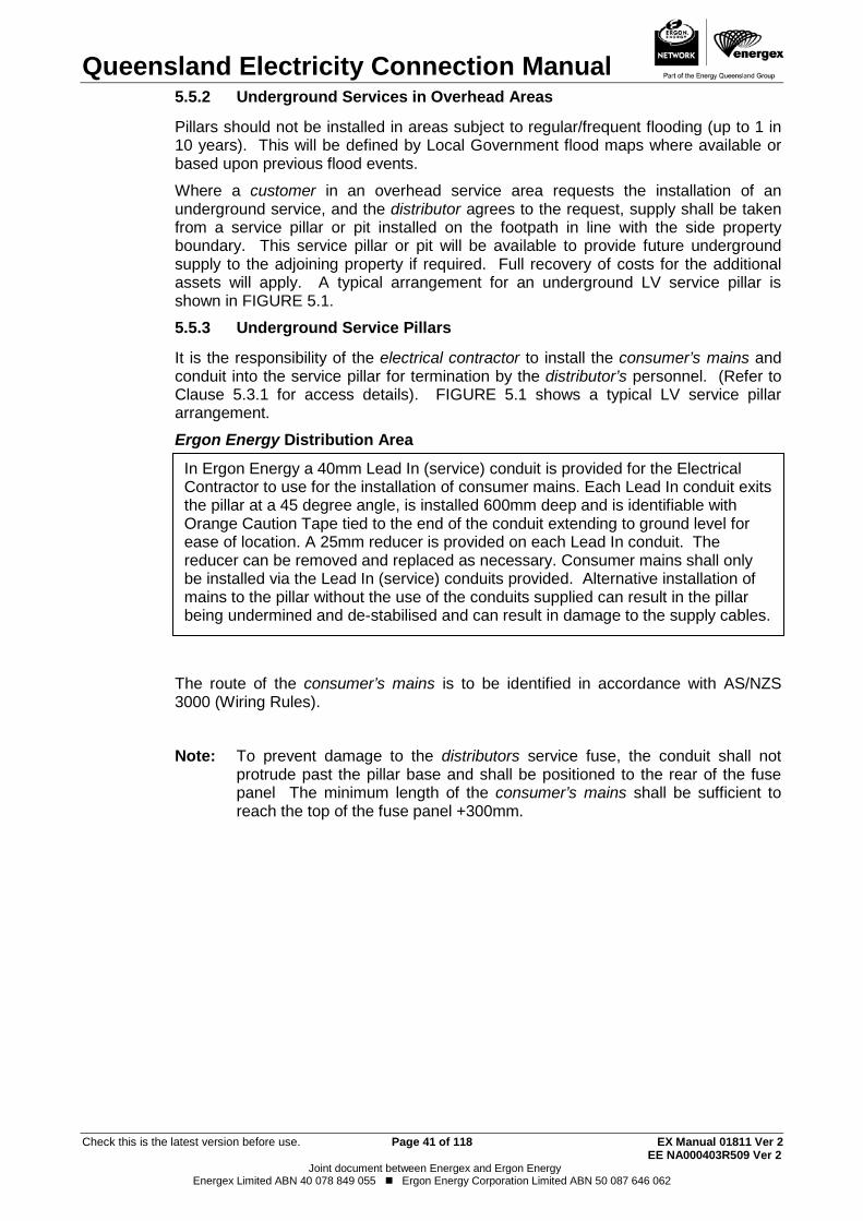
Queensland Electricity Connection Manual
Check this is the latest version before use. Page 41 of 118 EX Manual 01811 Ver 2 EE NA000403R509 Ver 2
Joint document between Energex and Ergon Energy Energex Limited ABN 40 078 849 055 Ergon Energy Corporation Limited ABN 50 087 646 062
Underground Services in Overhead Areas 5.5.2
Pillars should not be installed in areas subject to regular/frequent flooding (up to 1 in 10 years). This will be defined by Local Government flood maps where available or based upon previous flood events.
Where a customer in an overhead service area requests the installation of an underground service, and the distributor agrees to the request, supply shall be taken from a service pillar or pit installed on the footpath in line with the side property boundary. This service pillar or pit will be available to provide future underground supply to the adjoining property if required. Full recovery of costs for the additional assets will apply. A typical arrangement for an underground LV service pillar is shown in FIGURE 5.1.
Underground Service Pillars 5.5.3
It is the responsibility of the electrical contractor to install the consumer’s mains and conduit into the service pillar for termination by the distributor’s personnel. (Refer to Clause 5.3.1 for access details). FIGURE 5.1 shows a typical LV service pillar arrangement.
Ergon Energy Distribution Area
The route of the consumer’s mains is to be identified in accordance with AS/NZS 3000 (Wiring Rules).
Note: To prevent damage to the distributors service fuse, the conduit shall not
protrude past the pillar base and shall be positioned to the rear of the fuse panel The minimum length of the consumer’s mains shall be sufficient to reach the top of the fuse panel +300mm.
In Ergon Energy a 40mm Lead In (service) conduit is provided for the Electrical Contractor to use for the installation of consumer mains. Each Lead In conduit exits the pillar at a 45 degree angle, is installed 600mm deep and is identifiable with Orange Caution Tape tied to the end of the conduit extending to ground level for ease of location. A 25mm reducer is provided on each Lead In conduit. The reducer can be removed and replaced as necessary. Consumer mains shall only be installed via the Lead In (service) conduits provided. Alternative installation of mains to the pillar without the use of the conduits supplied can result in the pillar being undermined and de-stabilised and can result in damage to the supply cables.
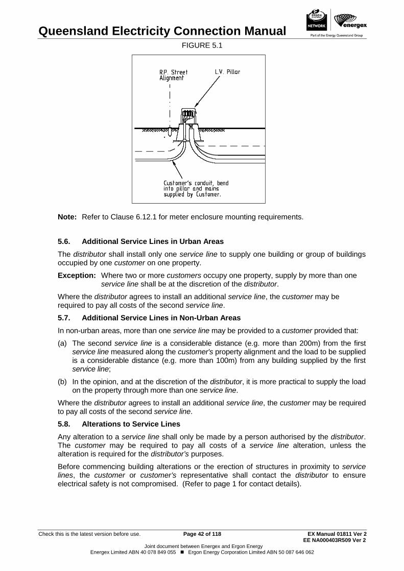
Queensland Electricity Connection Manual
Check this is the latest version before use. Page 42 of 118 EX Manual 01811 Ver 2 EE NA000403R509 Ver 2
Joint document between Energex and Ergon Energy Energex Limited ABN 40 078 849 055 Ergon Energy Corporation Limited ABN 50 087 646 062
FIGURE 5.1
Note: Refer to Clause 6.12.1 for meter enclosure mounting requirements.
Additional Service Lines in Urban Areas 5.6.The distributor shall install only one service line to supply one building or group of buildings occupied by one customer on one property.
Exception: Where two or more customers occupy one property, supply by more than one service line shall be at the discretion of the distributor.
Where the distributor agrees to install an additional service line, the customer may be required to pay all costs of the second service line.
Additional Service Lines in Non-Urban Areas 5.7.In non-urban areas, more than one service line may be provided to a customer provided that:
(a) The second service line is a considerable distance (e.g. more than 200m) from the first service line measured along the customer's property alignment and the load to be supplied is a considerable distance (e.g. more than 100m) from any building supplied by the first service line;
(b) In the opinion, and at the discretion of the distributor, it is more practical to supply the load on the property through more than one service line.
Where the distributor agrees to install an additional service line, the customer may be required to pay all costs of the second service line.
Alterations to Service Lines 5.8.Any alteration to a service line shall only be made by a person authorised by the distributor. The customer may be required to pay all costs of a service line alteration, unless the alteration is required for the distributor’s purposes.
Before commencing building alterations or the erection of structures in proximity to service lines, the customer or customer’s representative shall contact the distributor to ensure electrical safety is not compromised. (Refer to page 1 for contact details).
Queensland Electricity Connection Manual
Check this is the latest version before use. Page 43 of 118 EX Manual 01811 Ver 2 EE NA000403R509 Ver 2
Joint document between Energex and Ergon Energy Energex Limited ABN 40 078 849 055 Ergon Energy Corporation Limited ABN 50 087 646 062
Consumer’s mains on the Distributor’s Poles 5.9.In general, consumer’s mains shall not be installed on the distributor’s poles. However, approval at the discretion of the distributor may be given under the conditions set out in part (a) and (b) below:
(a) Unmetered Installations Unmetered installations are generally owned by a telecommunications company, public body (or affiliated operator) or other companies (approved by a public body) and installed on public land. (Refer to Clause 2.6).
When the installation does not meet the requirements of an unmetered supply (e.g. council public parks) it will be treated as a metered installation.
In no case shall the maximum demand of these installations exceed the rating of a standard overhead service (i.e. 100A per phase). This arrangement generally applies only to Rate 3 Public Lighting where a standard charge per light applies.
Where the above has been satisfied, approval may be granted for the public body (or affiliated operator) or other companies (approved by a public body) to install the consumer’s mains on poles designated by the distributor.
Note: Specific requirements apply (particular poles types are unsuitable). The customer must contact the distributor for details and approval.
(b) Metered Installations: In all cases this arrangement is totally at the discretion of the distributor and the following criteria must be satisfied:
(i) The supply network is within the boundaries of the customer’s property; and
(ii) The installation actual demand is above 400A (i.e. in excess of a standard overhead service arrangement); or
(iii) The electrical installation is owned by a Public Body or other companies (approved by a public body) and complies with the following -
• the installation is for the use of the general public; and
• the installation is installed on public land; and
• the public body or other companies (approved by a public body) is able to demonstrate that there is a community benefit in not installing a property pole (e.g. supply to parkland etc.); and
• the distributor’s network is within a reasonable distance from the connection point (i.e. not more than 20m); and
• the network is on the same side of the road as the installation; and
• the installation maximum demand is not greater than 100A per phase.
Note: Special conditions apply for all the above and approval, as well as the details of the requirements, must be obtained from the distributor prior to the commencement of any design or installation work. The customer shall meet all associated costs.
Substations on Customer's Premises 5.10.Where the aggregate maximum demand exceeds or is reasonably estimated to exceed 100kVA as determined by AS/NZS 3000 (Wiring Rules), the distributor may require a customer to provide free of charge the space necessary for a substation in accordance with the Electricity Regulation 2006.
Queensland Electricity Connection Manual
Check this is the latest version before use. Page 44 of 118 EX Manual 01811 Ver 2 EE NA000403R509 Ver 2
Joint document between Energex and Ergon Energy Energex Limited ABN 40 078 849 055 Ergon Energy Corporation Limited ABN 50 087 646 062
Consumer’s Mains Connections to Transformer Terminals 5.10.1
Where consumer’s mains originate at the terminals of a transformer, they shall be adequately supported and shall be connected to the transformer terminals by flexible braid connectors and adaptor plates.
The electrical contractor is responsible for the supply and installation of the low voltage support stand/terminal cover, flexible braid connectors, adaptor plates and consumer’s mains, plus any equipment required by the distributor’s Commercial and Industrial Substation Manual. (Refer to page 1 for details).
Multiple Transformers 5.10.2
Where multiple transformers supply a single switchboard each transformer must be connected to a separate bus section, however, a bus-tie switching arrangement is permitted provided:
(a) The bus-tie switches are fitted with fail safe interlocking devices to prevent paralleling of the supplies; and
(b) If the bus-tie switches are a type that cannot be operated under load, fitted with a warning label to indicate the operating requirements; and
(c) Be installed and identified in accordance with AS/NZS 3000 (Wiring Rules).
In general, where the distributor agrees to provide more than one connection point to an installation, the customer must ensure that the supplies cannot be connected in parallel.
Buried Earthing Systems 5.10.3
Provision of a high voltage substation requires the installation of buried earthing systems. These earthing systems are generally installed within 5m of the substation, however in some cases additional earthing cables may be required. These additional earthing cables would generally be located under the line and may extend some distance away from the substation. For safety reasons, it is important that building foundations, customers’ low voltage earths or other metallic structures be located a distance of at least 5m or more away from the high voltage earthing system. The distributor will provide advice on the location of the earthing system for specific installations if required.
Joints in Consumer’s mains 5.11.Joints in un-metered consumer’s mains are permitted provided they comply with AS/NZS 3000 (Wiring Rules) and are not vulnerable to tampering by re-instating insulation to equivalent of an unbroken cable.

Queensland Electricity Connection Manual
Check this is the latest version before use. Page 45 of 118 EX Manual 01811 Ver 2 EE NA000403R509 Ver 2
Joint document between Energex and Ergon Energy Energex Limited ABN 40 078 849 055 Ergon Energy Corporation Limited ABN 50 087 646 062
THIS PAGE HAS BEEN DELIBERATELY LEFT BLANK
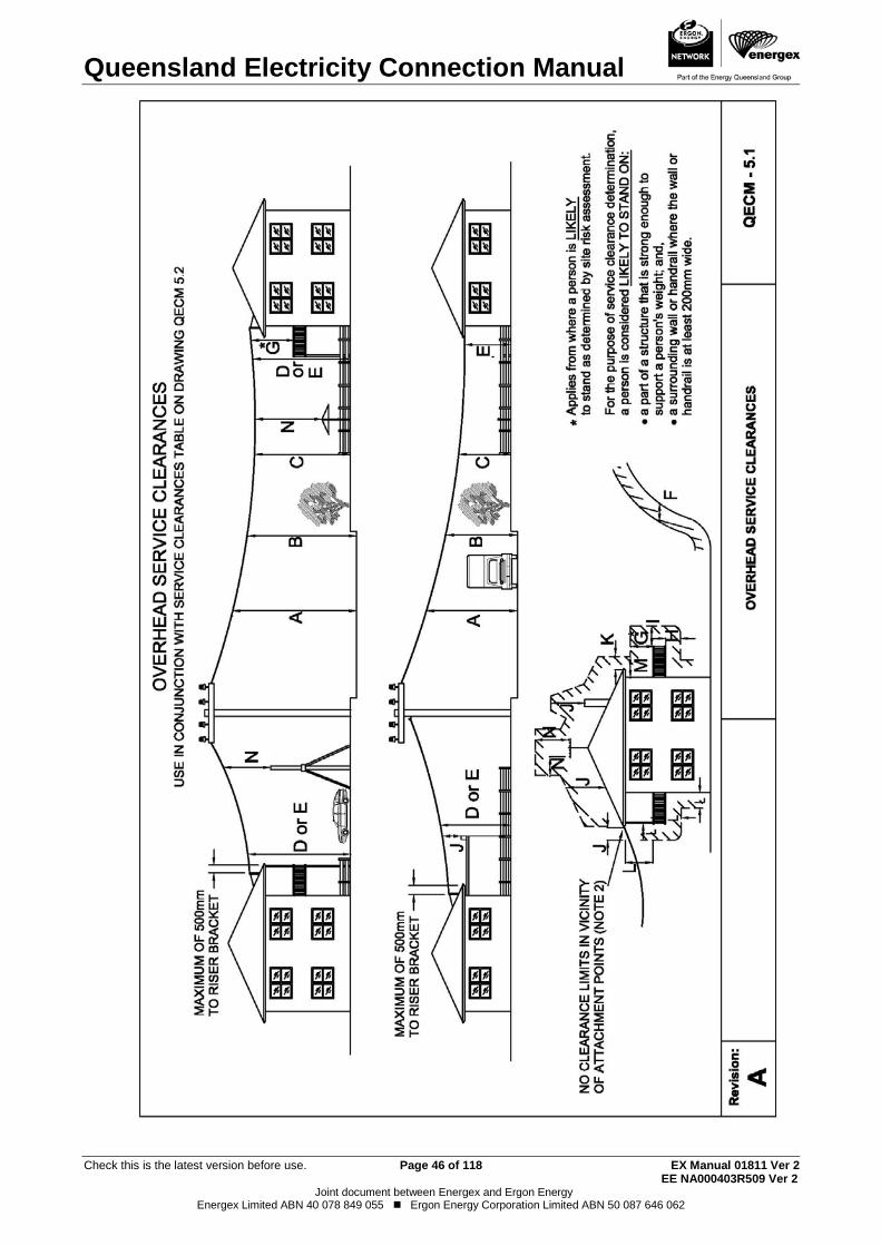
Queensland Electricity Connection Manual
Check this is the latest version before use. Page 46 of 118 EX Manual 01811 Ver 2 EE NA000403R509 Ver 2
Joint document between Energex and Ergon Energy Energex Limited ABN 40 078 849 055 Ergon Energy Corporation Limited ABN 50 087 646 062
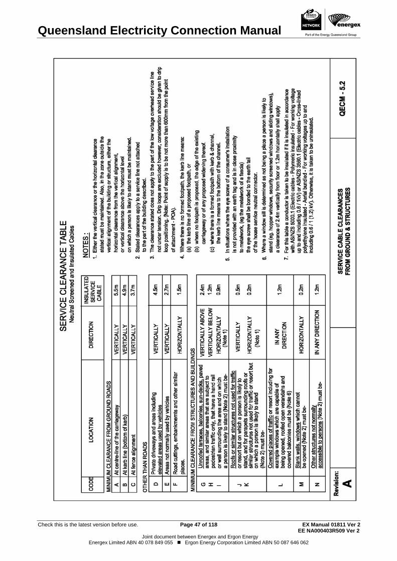
Queensland Electricity Connection Manual
Check this is the latest version before use. Page 47 of 118 EX Manual 01811 Ver 2 EE NA000403R509 Ver 2
Joint document between Energex and Ergon Energy Energex Limited ABN 40 078 849 055 Ergon Energy Corporation Limited ABN 50 087 646 062
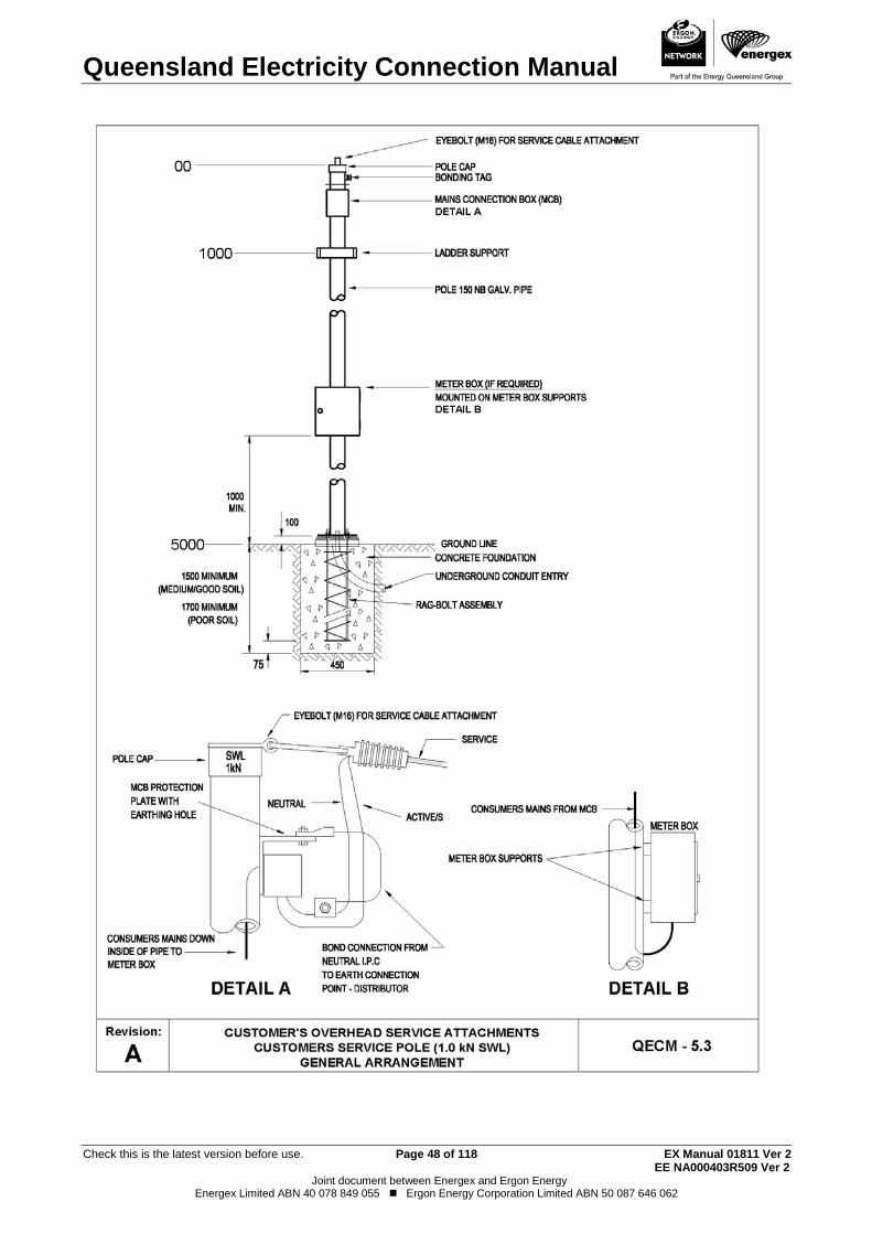
Queensland Electricity Connection Manual
Check this is the latest version before use. Page 48 of 118 EX Manual 01811 Ver 2 EE NA000403R509 Ver 2
Joint document between Energex and Ergon Energy Energex Limited ABN 40 078 849 055 Ergon Energy Corporation Limited ABN 50 087 646 062
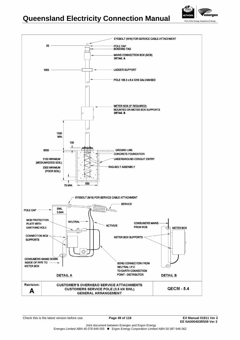
Queensland Electricity Connection Manual
Check this is the latest version before use. Page 49 of 118 EX Manual 01811 Ver 2 EE NA000403R509 Ver 2
Joint document between Energex and Ergon Energy Energex Limited ABN 40 078 849 055 Ergon Energy Corporation Limited ABN 50 087 646 062
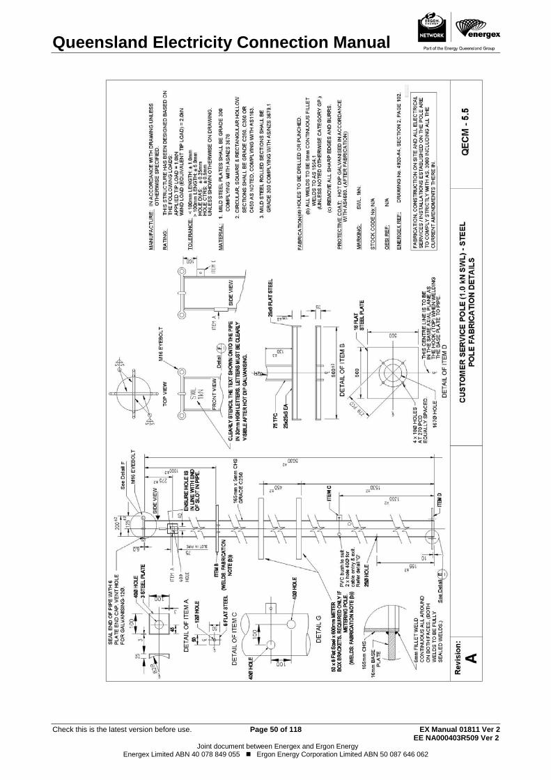
Queensland Electricity Connection Manual
Check this is the latest version before use. Page 50 of 118 EX Manual 01811 Ver 2 EE NA000403R509 Ver 2
Joint document between Energex and Ergon Energy Energex Limited ABN 40 078 849 055 Ergon Energy Corporation Limited ABN 50 087 646 062
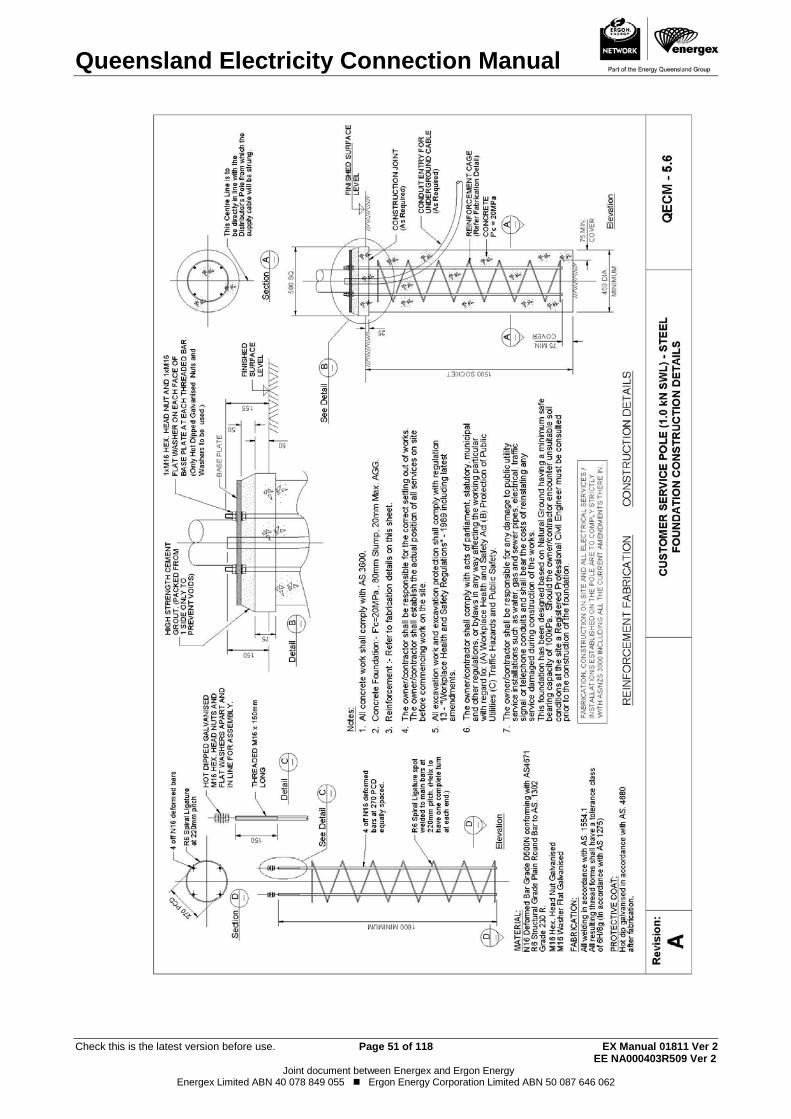
Queensland Electricity Connection Manual
Check this is the latest version before use. Page 51 of 118 EX Manual 01811 Ver 2 EE NA000403R509 Ver 2
Joint document between Energex and Ergon Energy Energex Limited ABN 40 078 849 055 Ergon Energy Corporation Limited ABN 50 087 646 062
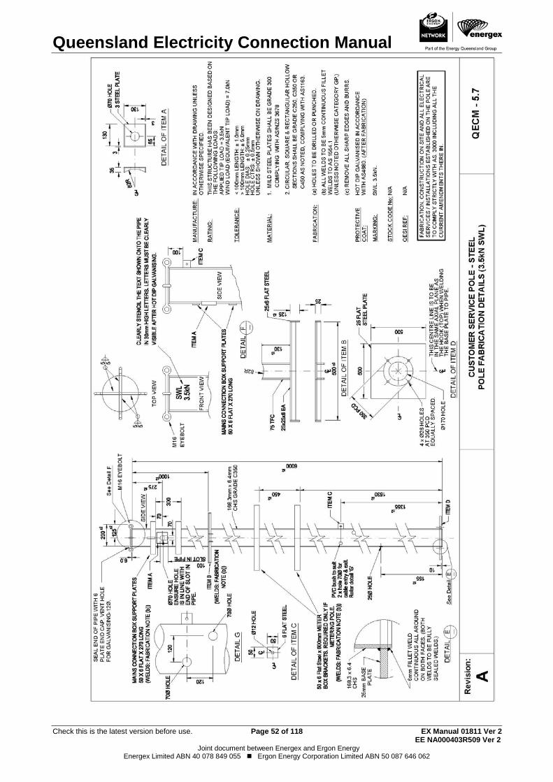
Queensland Electricity Connection Manual
Check this is the latest version before use. Page 52 of 118 EX Manual 01811 Ver 2 EE NA000403R509 Ver 2
Joint document between Energex and Ergon Energy Energex Limited ABN 40 078 849 055 Ergon Energy Corporation Limited ABN 50 087 646 062
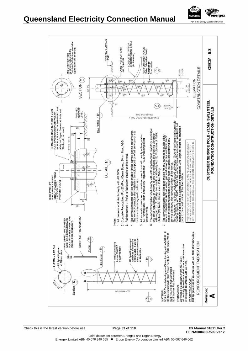
Queensland Electricity Connection Manual
Check this is the latest version before use. Page 53 of 118 EX Manual 01811 Ver 2 EE NA000403R509 Ver 2
Joint document between Energex and Ergon Energy Energex Limited ABN 40 078 849 055 Ergon Energy Corporation Limited ABN 50 087 646 062
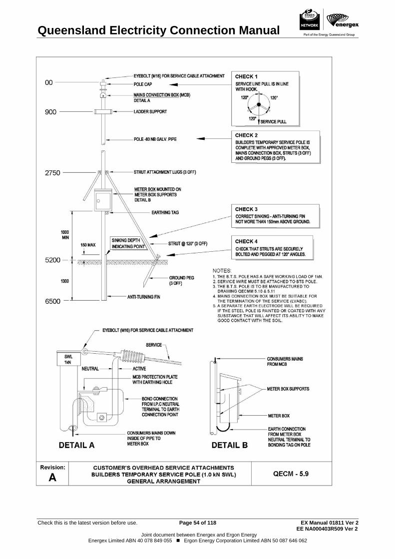
Queensland Electricity Connection Manual
Check this is the latest version before use. Page 54 of 118 EX Manual 01811 Ver 2 EE NA000403R509 Ver 2
Joint document between Energex and Ergon Energy Energex Limited ABN 40 078 849 055 Ergon Energy Corporation Limited ABN 50 087 646 062
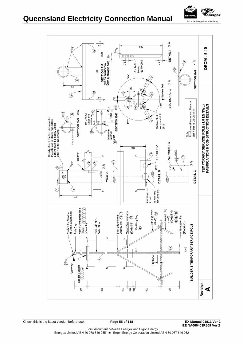
Queensland Electricity Connection Manual
Check this is the latest version before use. Page 55 of 118 EX Manual 01811 Ver 2 EE NA000403R509 Ver 2
Joint document between Energex and Ergon Energy Energex Limited ABN 40 078 849 055 Ergon Energy Corporation Limited ABN 50 087 646 062

Queensland Electricity Connection Manual
Check this is the latest version before use. Page 56 of 118 EX Manual 01811 Ver 2 EE NA000403R509 Ver 2
Joint document between Energex and Ergon Energy Energex Limited ABN 40 078 849 055 Ergon Energy Corporation Limited ABN 50 087 646 062
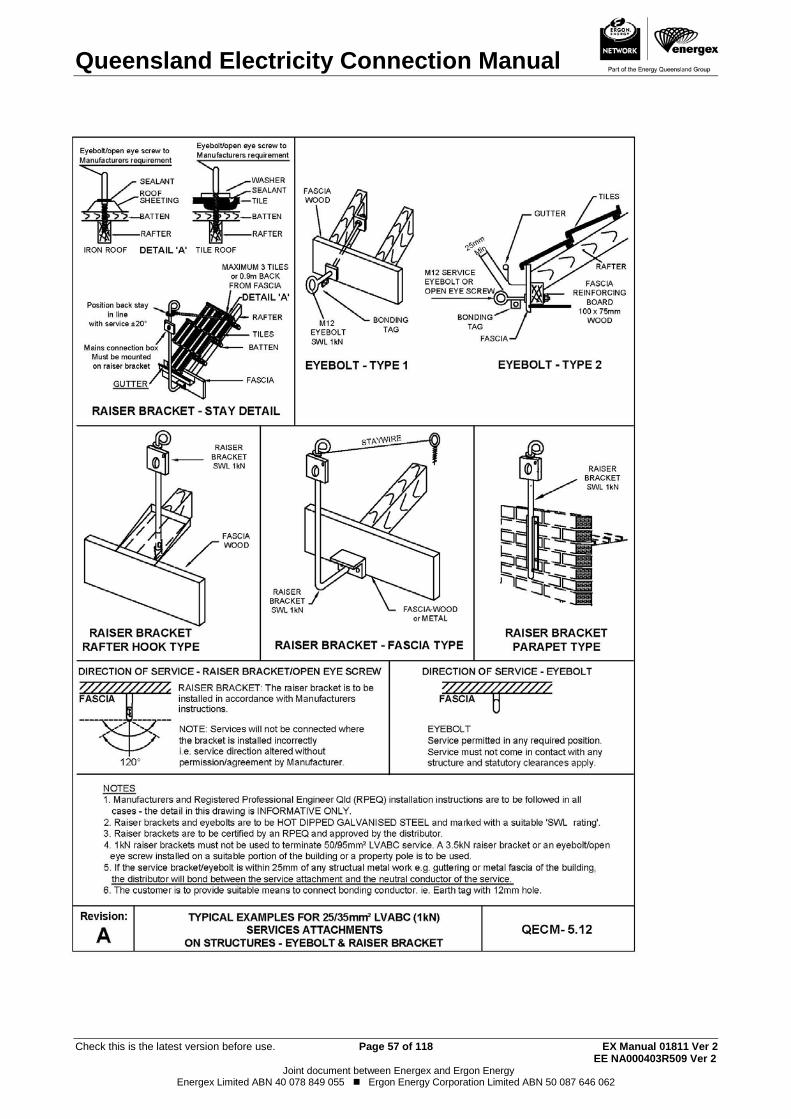
Queensland Electricity Connection Manual
Check this is the latest version before use. Page 57 of 118 EX Manual 01811 Ver 2 EE NA000403R509 Ver 2
Joint document between Energex and Ergon Energy Energex Limited ABN 40 078 849 055 Ergon Energy Corporation Limited ABN 50 087 646 062
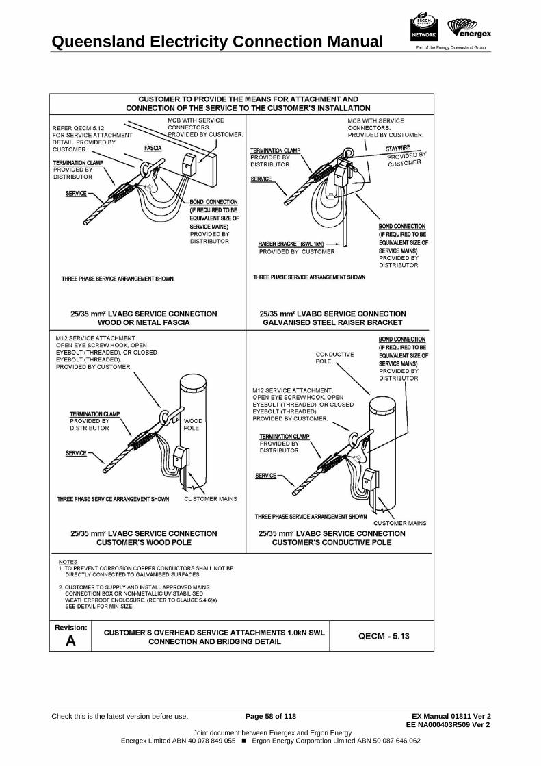
Queensland Electricity Connection Manual
Check this is the latest version before use. Page 58 of 118 EX Manual 01811 Ver 2 EE NA000403R509 Ver 2
Joint document between Energex and Ergon Energy Energex Limited ABN 40 078 849 055 Ergon Energy Corporation Limited ABN 50 087 646 062
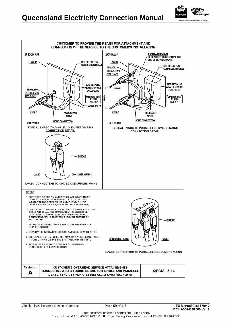
Queensland Electricity Connection Manual
Check this is the latest version before use. Page 59 of 118 EX Manual 01811 Ver 2 EE NA000403R509 Ver 2
Joint document between Energex and Ergon Energy Energex Limited ABN 40 078 849 055 Ergon Energy Corporation Limited ABN 50 087 646 062
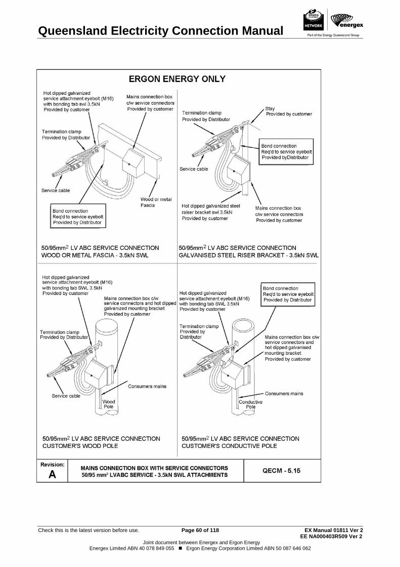
Queensland Electricity Connection Manual
Check this is the latest version before use. Page 60 of 118 EX Manual 01811 Ver 2 EE NA000403R509 Ver 2
Joint document between Energex and Ergon Energy Energex Limited ABN 40 078 849 055 Ergon Energy Corporation Limited ABN 50 087 646 062

Queensland Electricity Connection Manual
Check this is the latest version before use. Page 61 of 118 EX Manual 01811 Ver 2 EE NA000403R509 Ver 2
Joint document between Energex and Ergon Energy Energex Limited ABN 40 078 849 055 Ergon Energy Corporation Limited ABN 50 087 646 062
THIS PAGE HAS BEEN DELIBERATELY LEFT BLANK
Queensland Electricity Connection Manual
Check this is the latest version before use. Page 62 of 118 EX Manual 01811 Ver 2 EE NA000403R509 Ver 2
Joint document between Energex and Ergon Energy Energex Limited ABN 40 078 849 055 Ergon Energy Corporation Limited ABN 50 087 646 062
6. METERING REQUIREMENTS6.1. GeneralMetering installations are to comply with this document (QECM) and the Queensland Electricity Metering Manual (QEMM)
Where a customer directs a retailer to request metering or tariff changes, any alterations to the customer’s switchboard installation or meter enclosure shall be the customer’s responsibility (e.g. removal of asbestos contaminated waste) (Refer to Clause 6.7).
Network devices deemed to be necessary to control electricity consumption shall be supplied and maintained by the distributor and shall remain their property. All meter and network device active terminals shall be connected directly to the Metering Isolation Link or Metering Active Link for direct connected installations.
All phases of a service line are required to be connected at the initial connection of the premises.
All metering and control equipment shall be back-wired and mounted on a side hinged panel attached to a metering enclosure or a switchboard frame.
Customer's ancillary equipment such as surge diverters, voltmeters, phase failure relays etc. shall be connected on the load side of the revenue metering equipment. Customer owned current transformers for energy management are permitted on the line side of revenue metering equipment at multiple tenancy installations.
6.2. Controlled loads Where controlled loads are required (Controlled Supply/Night Rate tariffs), provision for a separate network device shall be made (Refer to Drawing QECM 6.1 for cable access drilling details). The network device will only be installed when the customer has requested controlled load as part of the EWR for the installation.
Section 7 contains more detail on requirements for connection of controlled loads
6.3. Metering Isolation To facilitate the requirements of the Electrical Safety Act 2002 and Electrical Safety Regulation 2013 for performing electrical work, and the Electricity Act 1994 and Electricity Regulation 2006, supply to the revenue metering equipment for each customer is to be capable of being individually isolated.
All metering shall be connected with suitable active isolation devices connected to the line side of the metering to allow safe access to the metering equipment.
Isolation of Direct Connected Metering 6.3.1
Direct connected metering shall be installed on the line side of the individual installation’s main switches.
6.3.1.1 Single Installations A metering isolation link per phase shall be connected to the line side of the metering. This arrangement maintains supply to electronic meters. (Refer to Clause 6.3.2 and Drawing QECM 6.2).
Exception:
Queensland Electricity Connection Manual
Check this is the latest version before use. Page 63 of 118 EX Manual 01811 Ver 2 EE NA000403R509 Ver 2
Joint document between Energex and Ergon Energy Energex Limited ABN 40 078 849 055 Ergon Energy Corporation Limited ABN 50 087 646 062
Where overload protection for the consumer’s mains, in accordance with AS/NZS 3000 (Wiring Rules), cannot be achieved by the positioning of the installation’s circuit breaker main switches on the load side of the metering the following shall apply:
A metering isolation D curve circuit breaker connected on the line side of the metering, and sized for overload protection of the consumer’s mains, shall be installed on the front of the meter panel in place of the metering isolation link. The circuit breaker shall be enclosed in a sealable non-metallic enclosure with a clear cover to allow the customer to determine if the circuit breaker is in the open or closed position without removing the cover and shall comply with rating limitations as per the QEMM.
Notes:
1. Enclosures that are lockable only are not acceptable.
2. The distributor’s service fuse shall not be considered as overload protection (refer to Clause 2.8).
3. Where metering isolation circuit breakers are used in a three phase installation, all three phases must have circuit breakers. If individual CBs are used they must comply with Clause 6..3.2.
If the marking on the circuit breaker is not legible when the cover is in place, the open and closed positions are to be identified by additional marking on the enclosure.
A permanent indelible label shall be fixed on or adjacent to the circuit breaker enclosure stating the following:
6.3.1.2 Multiple Installations A lockable load-break isolator (with facility for locking off) that is capable of isolating supply to the entire electrical installation shall be installed for all multiple customer installations including multiple customers fed from remote metering points. Where a circuit breaker main switch is installed for overload protection of the consumer’s mains in accordance with AS/NZS 3000 (Wiring Rules), it shall be lockable, connected on the line side of the metering and can be used in place of the building isolator (Refer to Drawings QECM 6.3-1 and 6.3-2).
Metering isolation links are required for individual customers. (Refer to Clause 6.3.2).
6.3.1.3 Metering Isolation - Existing Installations When minor work is being carried out at an existing installation (including a like for like meter change, network device change or connection of additional circuits) it will not be necessary to alter the wiring of the meter to before the main switch. (Refer to the notes below).
This change need only be made where there is a major alteration to the metering or switchboard (for example where the switchboard is replaced, when replacing single phase meters with a polyphase meter or connection of additional phase/s). This will include the addition of metering isolation link/s (Refer to Clause 6.3.1.1).
All meters at the one meter location must follow the same sequence (i.e. be either all “before” or all “after” the main switch/s or any lockable isolator).
Exceptions: 1. Where direct connected meters are installed to facilitate a customer requested
supply/tariff change, additional tariffs (e.g. controlled supply tariff) or installation
Metering isolation circuit breaker Contact an Electrical Contractor if off.
Queensland Electricity Connection Manual
Check this is the latest version before use. Page 64 of 118 EX Manual 01811 Ver 2 EE NA000403R509 Ver 2
Joint document between Energex and Ergon Energy Energex Limited ABN 40 078 849 055 Ergon Energy Corporation Limited ABN 50 087 646 062
of an Micro EG Unit on an existing single customer installation, they shall be connected on the line side of the individual installation's switchgear and provision for isolation is required in accordance with Clause 6.3.1.1.
2. On existing multi-tenancy installations where the individual tenancy main switch is connected on the line side of the meters, a new meter shall be connected on the line side of the individual tenancy main switch. A means of isolation in accordance with Clause 6.3.1.1 must be provided to allow isolation of the meter without interrupting supply to other customers.
3. On existing single phase multi-tenancy installations utilising plug-in meters, the need to fit isolation link/s is not required in situations where a replacement plug-in meter is to be used. These include a single phase tenancy with a Micro Embedded Generating (EG) Unit or a tenancy with Time of Use metering (TOU)
Notes for Clause 6.6.1.3: 1. Where the distributor’s service fuse is greater than 80A, fault current limiting
devices (supplied and installed by the customer) complying with AS/NZS 3000 (Wiring Rules), are required to protect any direct connected meters. Fault current limiting devices shall be installed as per AS/NZS3000. (Refer to Drawings QECM 6.3-1 and 6.3-2).
2. Standard practice in multiple tenancy direct connected metering installations, where the service fuse protection is greater than 100A, is to install a 80A fuse in the metering isolation link in place of the solid link. Where fuses are installed, the metering provider will provide the fuse and place a label on the panel adjacent to the metering isolation links stating: “WARNING - The metering isolation links have been fused for protection of metering provider Equipment”.
3. Where the metering provider determines that the meter requires an 80A fuse for adequate overload/fault protection, metering providers can install an 80A fuse in the metering isolation link provided the Maximum Demand of the installation does not exceed 80A. Should a 100A supply be required, the metering provider shall ensure the meter used is suitably rated for, and protected by, the 100A service fuse. All other requirements of Notes 1 and 2 above remain applicable.
Metering Isolation Links/CBs 6.3.2
Metering isolation links/CBs shall be installed in accordance with the following:
(a) Metering isolation links shall be clear cased type that comply with AS 60269, sealable, back wired, fitted with a tubular link and installed on the line side of all direct connected metering equipment; and
(b) All metering isolation links/CBs on a metering panel shall be connected in the same line - load sequence; and
(c) The metering isolation links shall be mounted horizontally or vertically on the front of the metering panel and if not obvious, clearly labelled to indicate the meter and portion of the installation that they control. Clearance around the ends of metering isolation links shall be 40mm; and
(d) The load through a metering isolation link/CB shall not exceed 125A. In multiple supply applications (e.g. general and controlled supplies), where the load exceeds 125A, additional metering isolation links/CBs shall be required. Where a fuse is used to replace the solid link (Refer to Clause 6.3.1.3) the maximum load through the metering isolation link shall not exceed the rating of the fuse; and
(e) On multiple installations metering isolation links/CBs shall be provided for each network device and installed on or adjacent to the relevant meter/metering equipment; and
Queensland Electricity Connection Manual
Check this is the latest version before use. Page 65 of 118 EX Manual 01811 Ver 2 EE NA000403R509 Ver 2
Joint document between Energex and Ergon Energy Energex Limited ABN 40 078 849 055 Ergon Energy Corporation Limited ABN 50 087 646 062
(f) For customers with three phase supply the metering isolation links/CBs are to be grouped together and if not obvious, permanent labelling must be applied to the meter panel to show the meter(s) and installation that they control.
Within the Energex distribution area where metering isolation links are fitted on an existing meter panel with surface wiring a front wired metering isolation link suitable for this purpose is acceptable.
Aluminium cables are not suitable for connection directly into Metering Isolation Link terminals unless fitted with a suitable means of termination, such as a soft-form bi-metallic sleeve or ferrule that is compatible with the Metering Isolation Link terminal metal.
Where cables of these types are used as consumers mains, they shall comply with the requirements of the electrical component/cable manufacturers and AS/NZS 3000, particularly in regard to termination and bending.
Isolation of Current Transformer Metering 6.3.3
Current Transformer metering shall be capable of being individually isolated by a suitable isolator or main switch. All isolation equipment shall be clearly identified and readily accessible and shall be installed and maintained by the customer.
Where direct connected metering is installed at the same switchboard as current transformer metering, the direct connected metering is to comply with Clause 6.3.1.
(a) Specific Single Customer Current Transformer Metered Installations Specific single customer current transformer metered installations include installations where:
(i) Supply to the installation is interrupted for extended continuous periods of time (>2 days) e.g. irrigation pumps, flood lifters, grain silos etc. (i.e. where the main switch is used to control the installation and leave the electronic meter without supply so that it cannot be read); or
(ii) “Safety Services” are installed and require supply to be maintained.
Note: AS/NZS 3000 (Wiring Rules) permits lockable isolators for installations supplying “Safety Services”.
In these specific single customer current transformer metered installations the customer shall install a lockable load-break isolator (with facility for locking on and off) on the line side of the current transformer metering chamber with the main switch(s) installed on the load side. In these specific installations, the isolator may be locked in the on position. (Refer to Drawing QECM 6.3-2). Where the metering current transformers are installed remote from the main switchboard, the isolator shall be marked “Metering Isolator”.
(b) Other Single Customer Current Transformer Metered Installations
This includes all other single customer current transformer metered installations where supply to the meter will not be interrupted for extended continuous periods of time.
The preferred arrangement is to connect all single customer current transformer metered installations as per (a) above, however, in the interests of reducing costs to the customer, a main switch used as the lockable isolator installed on the line side of the current transformer metering is permitted provided isolation of customer
Queensland Electricity Connection Manual
Check this is the latest version before use. Page 66 of 118 EX Manual 01811 Ver 2 EE NA000403R509 Ver 2
Joint document between Energex and Ergon Energy Energex Limited ABN 40 078 849 055 Ergon Energy Corporation Limited ABN 50 087 646 062
outgoing circuits is still provided on the same switchboard as the CTs. The main switch shall be capable of being locked in the off position. (Refer to Drawing QECM6.3-2).
(c) Multiple Customer Current Transformer Metered Installations (i) Isolation of entire installation (Building Isolator).
A lockable load-break isolator (with facility for locking off) that is capable of isolating supply to the entire electrical installation is required.
Note: A charge will be made where the distributor is required to isolate supply.
(ii) Isolation of individual customers. A lockable load-break isolator (with facility for locking off) shall be installed on the line side of each set of revenue metering current transformers with the customer’s main switch(s) installed on the load side located on the same switchboard as the CTs. (Refer to Drawings QECM 6.3-1 and 6.3-2).
Metering Active and Neutral Requirements 6.4. Connection of Metering Neutral Conductors to Main Neutral 6.4.1
The metering neutral shall be connected to the main neutral in such a manner that it cannot be disconnected or removed, e.g.
(a) Soldered or crimped to the main neutral;
(b) A flag lug under the main neutral connection. Slotted lugs shall not be used;
(c) A sealable terminal or bolt on the neutral link/bar where -
(ii) (i) the consumer’s mains are a busway or busbar arrangement;
(iii) the installation main switchboard is supplied by more than one connection point and a bus-tie arrangement is in place (the consumer’s mains neutrals shall be connected to a common neutral link/bar);
(d) Where the main neutral conductor is 25 mm2 or larger a sealable terminal may be used;
(e) Under a stud fitted with a suitable nut that is drilled and tapped into the consumer’s mains neutral lug, provided the arrangement can be sealed.
Note: In domestic installations where parallel consumer’s mains are used the metering neutral conductor shall be soldered to one conductor only.
Queensland Electricity Connection Manual
Check this is the latest version before use. Page 67 of 118 EX Manual 01811 Ver 2 EE NA000403R509 Ver 2
Joint document between Energex and Ergon Energy Energex Limited ABN 40 078 849 055 Ergon Energy Corporation Limited ABN 50 087 646 062
Accessibility of Neutral Connections 6.4.2
The metering neutral connection is to be readily accessible and shall not be located behind a panel where access requires isolation of supply.
On heavy current switchboards (Refer to AS/NZS 3000 (Wiring Rules)) the main neutral and MEN connections to the busbar shall be located in an accessible position with a minimum of 600mm clearance from exposed live parts. If a minimum clearance of 600mm cannot be achieved, the use of a permanent barrier or location within a chamber separate from that of the main switch or other exposed live parts is acceptable.
The arrangement must allow the main neutral and MEN connections to be safely accessed without isolating the supply to the switchboard or moving other cables. (Refer to AS/NZS 3000 (Wiring Rules)).
The use of shrouds over cable connections is not a sufficient barrier as the shrouds need to be removed during polarity testing (unless access to conductors is provided via test probe holes without the need to remove the shrouds).
Metering Neutral Links 6.4.3
The metering neutral shall be connected to a dedicated terminal of a metering neutral link.
All meter and network device neutral terminals shall be connected to a dedicated terminal of the metering neutral link via a separate neutral conductor.
Soldered meter and network device neutral connections are not permitted.
Existing installations
Where direct connected meters are installed to facilitate a customer requested supply/tariff change, additional tariffs (e.g. controlled supply tariff) or installation of an Micro EG Unit on an existing single customer installation, a metering neutral link shall be installed and connected as per the requirements of Clause 64.3.
Metering Active and Neutral Link Construction 6.4.4
Metering active and neutral links shall -
(a) incorporate a separate connecting device for the incoming and each outgoing circuit; and
(b) consist of tunnel terminals using either of methods (i); (ii) or (iii) for termination of the conductors.
(i) Two screws shall be provided for each terminal; or
(ii) One screw, the outside diameter of which is not less than 80% of the tunnel diameter; or
(iii) One screw, which is arranged so that the conductor is clamped by suitable ferrules or plates in direct contact with the conductor.
Where metering active or neutral links are used, they must be sealable or, where this facility does not exist (for larger sized consumer’s mains), the links must be installed within a suitable dedicated enclosure fitted with a sealable cover.
Metering Active and Neutral Link Mounting 6.4.5
Metering active and neutral links shall be mounted on the rear of the meter panel or meter enclosure.
Where metering active and neutral links are mounted on the rear of the meter panel, they shall be mounted in such a way that they do not interfere with the mounting of the metering equipment.
Queensland Electricity Connection Manual
Check this is the latest version before use. Page 68 of 118 EX Manual 01811 Ver 2 EE NA000403R509 Ver 2
Joint document between Energex and Ergon Energy Energex Limited ABN 40 078 849 055 Ergon Energy Corporation Limited ABN 50 087 646 062
To not interfere with metering equipment (normally mounted on the upper or middle section of the meter panel) it is preferable for the metering active and neutral links to be mounted as close as practical to the bottom of the meter panel.
Where metering active and neutral links are mounted on the rear of the meter enclosure and the material on which they are mounted is conductive, they shall be mounted on insulating material with low water absorption properties that will extend past the live parts of the link by a minimum of 25mm in all directions. This mounting arrangement is not required where the link has been specifically designed and type tested for installation onto metal surfaces.
Access to metering links must not be obstructed by any structure or wiring within the switchboard.
Metering Active and Neutral Link Labelling 6.4.6
A permanent label is required on the front of the meter panel to indicate the location of the metering active and neutral links.
Metering active and neutral links shall be identified as such and marked to identify which meter is fed from each outgoing circuit of the metering link. Labelling must be legible and durable in accordance with AS/NZS 3000.
Metering and Control Equipment - Accommodation 6.5.The customer shall provide and maintain at their expense, suitable space, housing, mounting and connecting facilities to accommodate meters and control equipment for each supply arrangement (e.g. general and controlled supplies).
Unless otherwise specified and agreed with the distributor, the minimum space requirements for high voltage metering panels shall be as specified in Section 9.
Metering and Control Equipment - Position 6.6. General 6.6.1
Meters and control equipment shall be positioned so that they are not subjected to mechanical damage, vibration, high temperature or other environmental situations that might affect their correct operation (e.g. exposure to direct sunlight). Where security of a meter enclosure is necessary, a metering lock must be purchased to allow access. (Refer to Clause 6.10).
The customer shall provide safe and ready access so that meters and control equipment may be fixed, read, tested, adjusted and removed without difficulty at any reasonable time but generally between the hours of 8.00am to 5.00pm Monday to Friday. The minimum access requirements for a meter enclosure shall be as per the requirements for switchboards as detailed in AS/NZS 3000 (Wiring Rules).
Unless otherwise approved by the distributor, or as varied by Clause 6.6.3, all meters and control equipment supplied for any one installation (as defined in the National Electricity Rules) shall be located in one readily accessible position, preferably on an outside wall at the front of the building.
Current transformer meters should be installed towards the front of the building on a readily accessible outside wall.
Direct connect meters shall be positioned in the same location as the Main switch and MEN point to allow required testing to be undertaken by the distributor.
Note: Where a property or building is of a type that may be subdivided, the meters and wiring should be located in an area that would be set aside as common property or within each individual lot.
Queensland Electricity Connection Manual
Check this is the latest version before use. Page 69 of 118 EX Manual 01811 Ver 2 EE NA000403R509 Ver 2
Joint document between Energex and Ergon Energy Energex Limited ABN 40 078 849 055 Ergon Energy Corporation Limited ABN 50 087 646 062
Domestic Properties 6.6.2
On domestic premises a meter position suitable to the distributor shall satisfy the following criteria:
(a) Unless otherwise approved in writing by the distributor, meters shall be erected on the side of the premises facing a street from which there is pedestrian access or within the first 2 m along an adjacent side of the premises. (Refer to Drawing QECM 6.4).
(b) Meters shall not be located behind any fence in an urban area, other than the perimeter fence located at the extremities of the property boundary.
Where access to meters is through locked gates in the perimeter fence, the distributor’s metering lock purchased from an authorised locksmith must be installed. The lock must be accessible from outside the gate. (Refer to Clause 6.10).
Note: Key/security card boxes or dual locking bars are acceptable.
(c) On domestic rural or urban properties greater than half a hectare, the metering equipment shall be situated in a readily accessible position in accordance with (a) and or (d) of this clause.
(d) For acreage and farm properties the metering equipment shall be accessible by motor vehicles.
Note: The preferred meter position is at the main residence, central meter position or at the front property boundary.
Unmetered Submains 6.6.3
6.6.3.1 Unmetered Submains - General Details of the proposed meter positions, unmetered submains and their circuit protective devices shall be submitted to the distributor for approval before their installation.
Exception: Approval is not required where the unmetered submains comply with Clauses 6.6.3.3 to 6.6.3.5.
Voltage drop on unmetered submains shall not exceed 2.5% of the supply voltage (voltage drop calculations must be included with the submission). (Refer to page 1 for contact details).
6.6.3.2 Meter Positions – Multiple Metering Points Installations with multiple metering points as detailed in Clauses 6.6.3.3 and 6.6.3.4 are to have community metering (where required) located on the main switchboard.
6.6.3.3 High Rise Buildings For buildings up to four floors, a single meter position on common property on the ground floor is approved.
For high rise buildings in excess of four floors, one meter position on every floor is approved.
6.6.3.4 Shopping Centres For shopping centres, other than high rise buildings complying with Clause 6.6.3.3 above, an additional metering point for every twelve customers will be permitted.
6.6.3.5 Community (Strata) Title and Cluster Developments For reticulation in community title or cluster developments that is not owned by the distributor, in general the distributor will provide one connection point to the installation. Unless otherwise approved by the distributor, all community metering
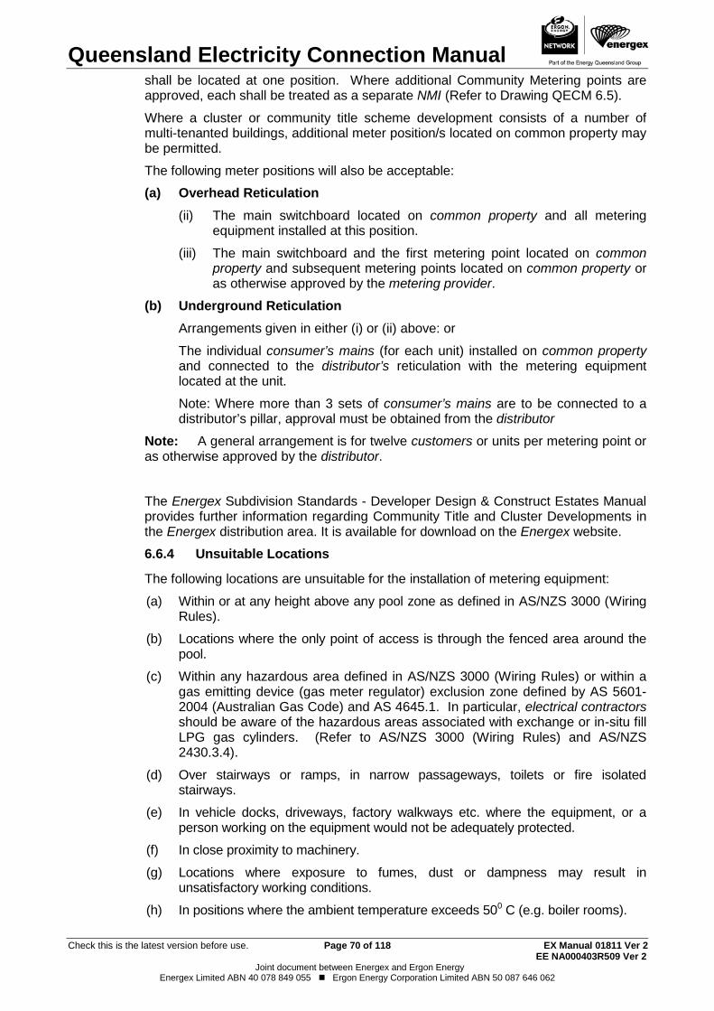
Queensland Electricity Connection Manual
Check this is the latest version before use. Page 70 of 118 EX Manual 01811 Ver 2 EE NA000403R509 Ver 2
Joint document between Energex and Ergon Energy Energex Limited ABN 40 078 849 055 Ergon Energy Corporation Limited ABN 50 087 646 062
shall be located at one position. Where additional Community Metering points are approved, each shall be treated as a separate NMI (Refer to Drawing QECM 6.5).
Where a cluster or community title scheme development consists of a number of multi-tenanted buildings, additional meter position/s located on common property may be permitted.
The following meter positions will also be acceptable:
(a) Overhead Reticulation (ii) The main switchboard located on common property and all metering
equipment installed at this position.
(iii) The main switchboard and the first metering point located on common property and subsequent metering points located on common property or as otherwise approved by the metering provider.
(b) Underground Reticulation Arrangements given in either (i) or (ii) above: or
The individual consumer’s mains (for each unit) installed on common property and connected to the distributor’s reticulation with the metering equipment located at the unit.
Note: Where more than 3 sets of consumer’s mains are to be connected to a distributor’s pillar, approval must be obtained from the distributor
Note: A general arrangement is for twelve customers or units per metering point or as otherwise approved by the distributor.
The Energex Subdivision Standards - Developer Design & Construct Estates Manual provides further information regarding Community Title and Cluster Developments in the Energex distribution area. It is available for download on the Energex website.
Unsuitable Locations 6.6.4
The following locations are unsuitable for the installation of metering equipment:
(a) Within or at any height above any pool zone as defined in AS/NZS 3000 (Wiring Rules).
(b) Locations where the only point of access is through the fenced area around the pool.
(c) Within any hazardous area defined in AS/NZS 3000 (Wiring Rules) or within a gas emitting device (gas meter regulator) exclusion zone defined by AS 5601-2004 (Australian Gas Code) and AS 4645.1. In particular, electrical contractors should be aware of the hazardous areas associated with exchange or in-situ fill LPG gas cylinders. (Refer to AS/NZS 3000 (Wiring Rules) and AS/NZS 2430.3.4).
(d) Over stairways or ramps, in narrow passageways, toilets or fire isolated stairways.
(e) In vehicle docks, driveways, factory walkways etc. where the equipment, or a person working on the equipment would not be adequately protected.
(f) In close proximity to machinery.
(g) Locations where exposure to fumes, dust or dampness may result in unsatisfactory working conditions.
(h) In positions where the ambient temperature exceeds 500 C (e.g. boiler rooms).
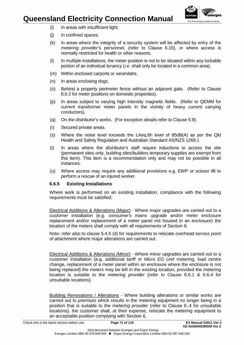
Queensland Electricity Connection Manual
Check this is the latest version before use. Page 71 of 118 EX Manual 01811 Ver 2 EE NA000403R509 Ver 2
Joint document between Energex and Ergon Energy Energex Limited ABN 40 078 849 055 Ergon Energy Corporation Limited ABN 50 087 646 062
(i) In areas with insufficient light.
(j) In confined spaces.
(k) In areas where the integrity of a security system will be affected by entry of the metering provider’s personnel, (refer to Clause 6.10), or where access is normally restricted for health or other reasons.
(l) In multiple installations, the meter position is not to be situated within any lockable portion of an individual tenancy (i.e. shall only be located in a common area).
(m) Within enclosed carports or verandahs.
(n) In areas enclosing dogs.
(o) Behind a property perimeter fence without an adjacent gate. (Refer to Clause 6.6.2 for meter positions on domestic properties).
(p) In areas subject to varying high intensity magnetic fields. (Refer to QEMM for current transformer meter panels in the vicinity of heavy current carrying conductors).
(q) On the distributor’s works. (For exception details refer to Clause 5.9).
(r) Secured private areas.
(s) Where the noise level exceeds the LAeq.8h level of 85dB(A) as per the Qld Health and Safety Regulation and Australian Standard AS/NZS 1269.1
(t) In areas where the distributor’s staff require inductions to access the site (permanent sites only, building sites/builders temporary supplies are exempt from this item). This item is a recommendation only and may not be possible in all instances.
(u) Where access may require any additional provisions e.g. EWP or scissor lift to perform a rescue of an injured worker.
Existing Installations 6.6.5
Where work is performed on an existing installation, compliance with the following requirements must be satisfied;
Electrical Additions & Alterations (Major) - Where major upgrades are carried out to a customer installation (e.g. consumer’s mains upgrade and/or meter enclosure replacement and/or replacement of a meter panel not housed in an enclosure) the location of the meters shall comply with all requirements of Section 6.
Note: refer also to clause 5.4.5 (d) for requirements to relocate overhead service point of attachment where major alterations are carried out.
Electrical Additions & Alterations (Minor) - Where minor upgrades are carried out to a customer installation (e.g. additional tariff or Micro EG Unit metering, load centre change, replacement of a meter panel within an enclosure where the enclosure is not being replaced) the meters may be left in the existing location, provided the metering location is suitable to the metering provider (refer to Clause 6.6.1 & 6.6.4 for unsuitable locations).
Building Renovations / Alterations - Where building alterations or similar works are carried out to premises which results in the metering equipment no longer being in a position that is suitable to the metering provider (refer to Clause 6..4 for unsuitable locations), the customer shall, at their expense, relocate the metering equipment to an acceptable position complying with Section 6.
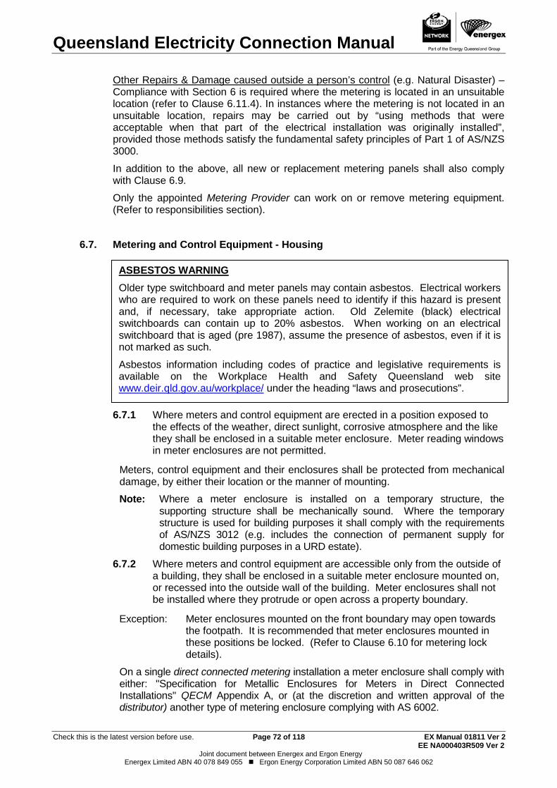
Queensland Electricity Connection Manual
Check this is the latest version before use. Page 72 of 118 EX Manual 01811 Ver 2 EE NA000403R509 Ver 2
Joint document between Energex and Ergon Energy Energex Limited ABN 40 078 849 055 Ergon Energy Corporation Limited ABN 50 087 646 062
Other Repairs & Damage caused outside a person’s control (e.g. Natural Disaster) – Compliance with Section 6 is required where the metering is located in an unsuitable location (refer to Clause 6.11.4). In instances where the metering is not located in an unsuitable location, repairs may be carried out by “using methods that were acceptable when that part of the electrical installation was originally installed”, provided those methods satisfy the fundamental safety principles of Part 1 of AS/NZS 3000.
In addition to the above, all new or replacement metering panels shall also comply with Clause 6.9.
Only the appointed Metering Provider can work on or remove metering equipment. (Refer to responsibilities section).
Metering and Control Equipment - Housing 6.7.
Where meters and control equipment are erected in a position exposed to 6.7.1the effects of the weather, direct sunlight, corrosive atmosphere and the like they shall be enclosed in a suitable meter enclosure. Meter reading windows in meter enclosures are not permitted.
Meters, control equipment and their enclosures shall be protected from mechanical damage, by either their location or the manner of mounting.
Note: Where a meter enclosure is installed on a temporary structure, the supporting structure shall be mechanically sound. Where the temporary structure is used for building purposes it shall comply with the requirements of AS/NZS 3012 (e.g. includes the connection of permanent supply for domestic building purposes in a URD estate).
Where meters and control equipment are accessible only from the outside of 6.7.2a building, they shall be enclosed in a suitable meter enclosure mounted on, or recessed into the outside wall of the building. Meter enclosures shall not be installed where they protrude or open across a property boundary.
Exception: Meter enclosures mounted on the front boundary may open towards the footpath. It is recommended that meter enclosures mounted in these positions be locked. (Refer to Clause 6.10 for metering lock details).
On a single direct connected metering installation a meter enclosure shall comply with either: "Specification for Metallic Enclosures for Meters in Direct Connected Installations" QECM Appendix A, or (at the discretion and written approval of the distributor) another type of metering enclosure complying with AS 6002.
ASBESTOS WARNING Older type switchboard and meter panels may contain asbestos. Electrical workers who are required to work on these panels need to identify if this hazard is present and, if necessary, take appropriate action. Old Zelemite (black) electrical switchboards can contain up to 20% asbestos. When working on an electrical switchboard that is aged (pre 1987), assume the presence of asbestos, even if it is not marked as such.
Asbestos information including codes of practice and legislative requirements is available on the Workplace Health and Safety Queensland web site www.deir.qld.gov.au/workplace/ under the heading “laws and prosecutions”.
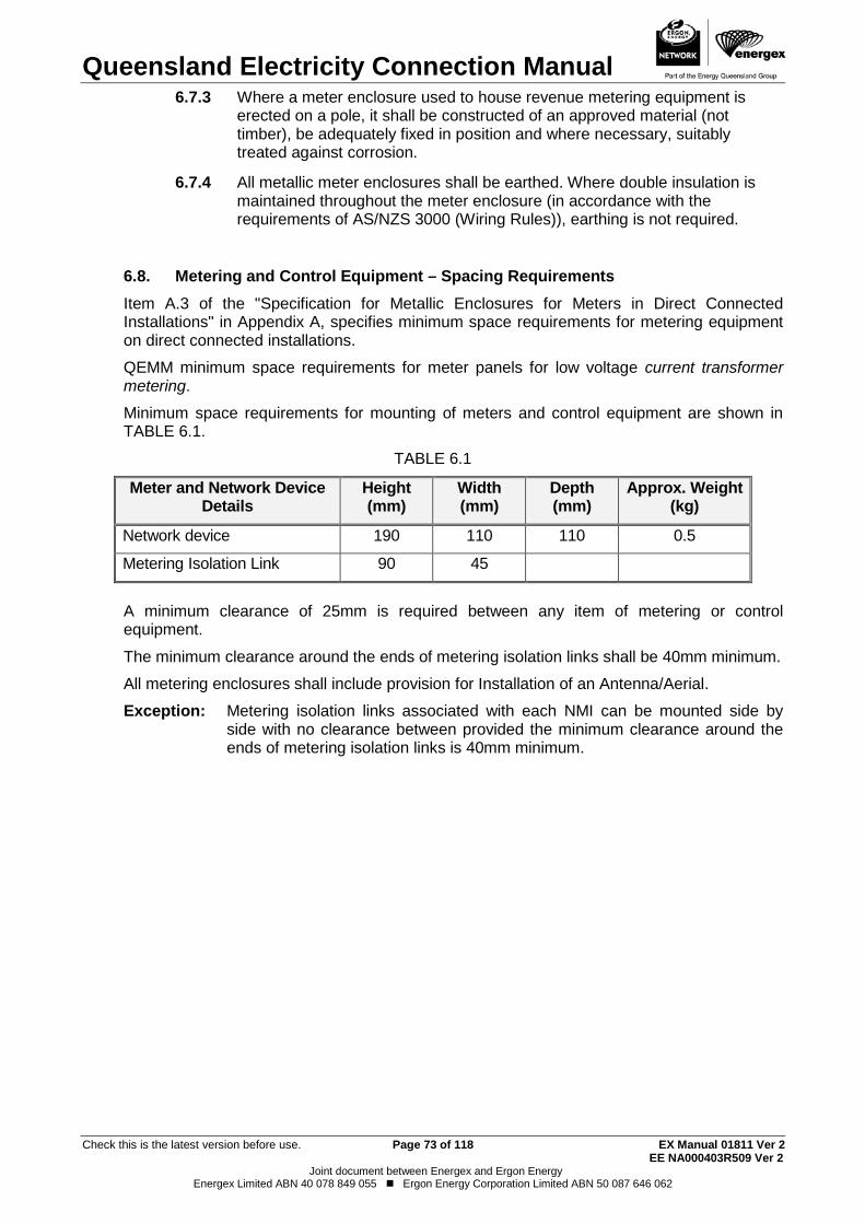
Queensland Electricity Connection Manual
Check this is the latest version before use. Page 73 of 118 EX Manual 01811 Ver 2 EE NA000403R509 Ver 2
Joint document between Energex and Ergon Energy Energex Limited ABN 40 078 849 055 Ergon Energy Corporation Limited ABN 50 087 646 062
Where a meter enclosure used to house revenue metering equipment is 6.7.3erected on a pole, it shall be constructed of an approved material (not timber), be adequately fixed in position and where necessary, suitably treated against corrosion.
All metallic meter enclosures shall be earthed. Where double insulation is 6.7.4maintained throughout the meter enclosure (in accordance with the requirements of AS/NZS 3000 (Wiring Rules)), earthing is not required.
Metering and Control Equipment – Spacing Requirements 6.8.
Item A.3 of the "Specification for Metallic Enclosures for Meters in Direct Connected Installations" in Appendix A, specifies minimum space requirements for metering equipment on direct connected installations.
QEMM minimum space requirements for meter panels for low voltage current transformer metering.
Minimum space requirements for mounting of meters and control equipment are shown in TABLE 6.1.
TABLE 6.1
Meter and Network Device Details
Height (mm)
Width (mm)
Depth (mm)
Approx. Weight (kg)
Network device 190 110 110 0.5
Metering Isolation Link 90 45
A minimum clearance of 25mm is required between any item of metering or control equipment.
The minimum clearance around the ends of metering isolation links shall be 40mm minimum.
All metering enclosures shall include provision for Installation of an Antenna/Aerial.
Exception: Metering isolation links associated with each NMI can be mounted side by side with no clearance between provided the minimum clearance around the ends of metering isolation links is 40mm minimum.
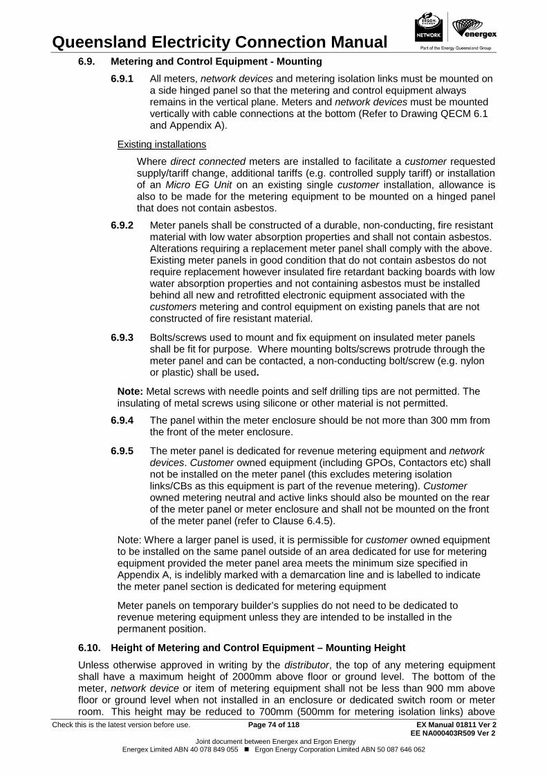
Queensland Electricity Connection Manual
Check this is the latest version before use. Page 74 of 118 EX Manual 01811 Ver 2 EE NA000403R509 Ver 2
Joint document between Energex and Ergon Energy Energex Limited ABN 40 078 849 055 Ergon Energy Corporation Limited ABN 50 087 646 062
Metering and Control Equipment - Mounting 6.9. All meters, network devices and metering isolation links must be mounted on 6.9.1
a side hinged panel so that the metering and control equipment always remains in the vertical plane. Meters and network devices must be mounted vertically with cable connections at the bottom (Refer to Drawing QECM 6.1 and Appendix A).
Existing installations
Where direct connected meters are installed to facilitate a customer requested supply/tariff change, additional tariffs (e.g. controlled supply tariff) or installation of an Micro EG Unit on an existing single customer installation, allowance is also to be made for the metering equipment to be mounted on a hinged panel that does not contain asbestos.
Meter panels shall be constructed of a durable, non-conducting, fire resistant 6.9.2material with low water absorption properties and shall not contain asbestos. Alterations requiring a replacement meter panel shall comply with the above. Existing meter panels in good condition that do not contain asbestos do not require replacement however insulated fire retardant backing boards with low water absorption properties and not containing asbestos must be installed behind all new and retrofitted electronic equipment associated with the customers metering and control equipment on existing panels that are not constructed of fire resistant material.
Bolts/screws used to mount and fix equipment on insulated meter panels 6.9.3shall be fit for purpose. Where mounting bolts/screws protrude through the meter panel and can be contacted, a non-conducting bolt/screw (e.g. nylon or plastic) shall be used.
Note: Metal screws with needle points and self drilling tips are not permitted. The insulating of metal screws using silicone or other material is not permitted.
The panel within the meter enclosure should be not more than 300 mm from 6.9.4the front of the meter enclosure.
The meter panel is dedicated for revenue metering equipment and network 6.9.5devices. Customer owned equipment (including GPOs, Contactors etc) shall not be installed on the meter panel (this excludes metering isolation links/CBs as this equipment is part of the revenue metering). Customer owned metering neutral and active links should also be mounted on the rear of the meter panel or meter enclosure and shall not be mounted on the front of the meter panel (refer to Clause 6.4.5).
Note: Where a larger panel is used, it is permissible for customer owned equipment to be installed on the same panel outside of an area dedicated for use for metering equipment provided the meter panel area meets the minimum size specified in Appendix A, is indelibly marked with a demarcation line and is labelled to indicate the meter panel section is dedicated for metering equipment
Meter panels on temporary builder’s supplies do not need to be dedicated to revenue metering equipment unless they are intended to be installed in the permanent position.
Height of Metering and Control Equipment – Mounting Height 6.10.Unless otherwise approved in writing by the distributor, the top of any metering equipment shall have a maximum height of 2000mm above floor or ground level. The bottom of the meter, network device or item of metering equipment shall not be less than 900 mm above floor or ground level when not installed in an enclosure or dedicated switch room or meter room. This height may be reduced to 700mm (500mm for metering isolation links) above
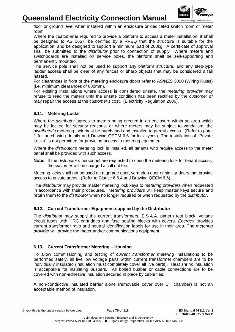
Queensland Electricity Connection Manual
Check this is the latest version before use. Page 75 of 118 EX Manual 01811 Ver 2 EE NA000403R509 Ver 2
Joint document between Energex and Ergon Energy Energex Limited ABN 40 078 849 055 Ergon Energy Corporation Limited ABN 50 087 646 062
floor or ground level when installed within an enclosure or dedicated switch room or meter room. Where the customer is required to provide a platform to access a meter installation, it shall be designed to AS 1657, be certified by a RPEQ that the structure is suitable for the application, and be designed to support a minimum load of 200kg. A certificate of approval shall be submitted to the distributor prior to connection of supply. Where meters and switchboards are installed on service poles, the platform shall be self-supporting and permanently mounted. The service pole shall not be used to support any platform structure, and any step-type ladder access shall be clear of any fences or sharp objects that may be considered a fall hazard. For clearances in front of the metering enclosure doors refer to AS/NZS 3000 (Wiring Rules) (i.e. minimum clearances of 600mm). For existing installations where access is considered unsafe, the metering provider may refuse to read the meters until the unsafe condition has been rectified by the customer or may repair the access at the customer’s cost. (Electricity Regulation 2006).
Metering Locks 6.11.Where the distributor agrees to meters being erected in an enclosure within an area which may be locked for security reasons, or where meters may be subject to vandalism, the distributor’s metering lock must be purchased and installed to permit access. (Refer to page 1 for purchasing details and Drawing QECM 6.6 for lock types). The installation of “Private Locks” is not permitted for providing access to metering equipment.
Where the distributor’s metering lock is installed, all tenants who require access to the meter panel shall be provided with such access.
Note: If the distributor’s personnel are requested to open the metering lock for tenant access, the customer will be charged a call out fee.
Metering locks shall not be used on a garage door, verandah door or similar doors that provide access to private areas. (Refer to Clause 6.6.4 and Drawing QECM 6.6).
The distributor may provide master metering lock keys to metering providers when requested in accordance with their procedures. Metering providers will keep master keys secure and return them to the distributor when no longer required or when requested by the distributor.
Current Transformer Equipment supplied by the Distributor 6.12.The distributor may supply the current transformers, E.S.A.A. pattern test block, voltage circuit fuses with HRC cartridges and fuse sealing blocks with covers. Energex provides current transformer ratio and neutral identification labels for use in their area. The metering provider will provide the meter and/or communications equipment.
Current Transformer Metering – Housing 6.13.To allow commissioning and testing of current transformer metering installations to be performed safely, all live low voltage parts within current transformer chambers are to be individually insulated (insulation must completely cover all live parts). Heat shrink insulation is acceptable for insulating busbars. All bolted busbar or cable connections are to be covered with non-adhesive insulation secured in place by cable ties.
A non-conductive insulated barrier alone (removable cover over CT chamber) is not an acceptable method of insulation.
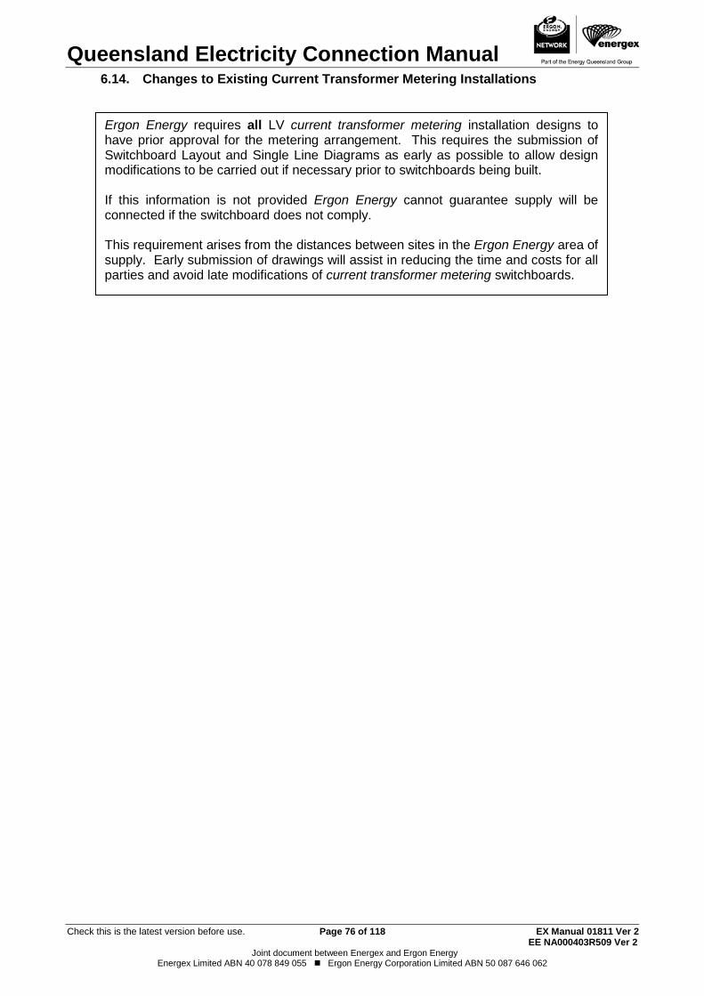
Queensland Electricity Connection Manual
Check this is the latest version before use. Page 76 of 118 EX Manual 01811 Ver 2 EE NA000403R509 Ver 2
Joint document between Energex and Ergon Energy Energex Limited ABN 40 078 849 055 Ergon Energy Corporation Limited ABN 50 087 646 062
Changes to Existing Current Transformer Metering Installations 6.14.
Ergon Energy requires all LV current transformer metering installation designs to have prior approval for the metering arrangement. This requires the submission of Switchboard Layout and Single Line Diagrams as early as possible to allow design modifications to be carried out if necessary prior to switchboards being built. If this information is not provided Ergon Energy cannot guarantee supply will be connected if the switchboard does not comply. This requirement arises from the distances between sites in the Ergon Energy area of supply. Early submission of drawings will assist in reducing the time and costs for all parties and avoid late modifications of current transformer metering switchboards.
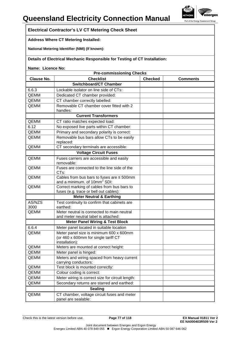
Queensland Electricity Connection Manual
Check this is the latest version before use. Page 77 of 118 EX Manual 01811 Ver 2 EE NA000403R509 Ver 2
Joint document between Energex and Ergon Energy Energex Limited ABN 40 078 849 055 Ergon Energy Corporation Limited ABN 50 087 646 062
Electrical Contractor’s LV CT Metering Check Sheet
Address Where CT Metering Installed: National Metering Identifier (NMI) (If known):
Details of Electrical Mechanic Responsible for Testing of CT Installation: Name: Licence No:
Pre-commissioning Checks
Clause No.
Checklist
Checked
Comments Switchboard/CT Chamber 6.6.3 Lockable isolator on line side of CTs: QEMM Dedicated CT chamber provided: QEMM CT chamber correctly labelled: QEMM Removable CT chamber cover fitted with 2
handles:
Current Transformers QEMM CT ratio matches expected load: 6.12 No exposed live parts within CT chamber: QEMM Primary and secondary polarity is correct: QEMM Removable bus bars allow CTs to be easily
replaced:
QEMM CT secondary terminals are accessible: Voltage Circuit Fuses QEMM Fuses carriers are accessible and easily
removable:
QEMM Fuses are connected to the line side of the CTs:
QEMM Cables from bus bars to fuses are ≤ 500mm and a minimum. of 10mm2 SDI:
QEMM Correct marking of cables from bus bars to fuses (e.g. trace or bell out cables):
Meter Neutral & Earthing AS/NZS 3000
Test continuity to confirm that cabinets are earthed:
QEMM Meter neutral is connected to main neutral and meter neutral label is attached:
Meter Panel Wiring & Test Block 6.6.4 Meter panel located in suitable location QEMM Meter panel size is minimum 600 x 600mm
(or 460 x 600mm for single tariff CT installation):
QEMM Meters are mounted at correct height: QEMM Meter panel is hinged: QEMM Meters and wiring spaced from heavy current
carrying conductors:
QEMM Test block is mounted correctly: QEMM Colour coding is correct: QEMM Meter wiring is correct size for circuit length: QEMM Secondary returns are starred and earthed: Sealing QEMM CT chamber, voltage circuit fuses and meter
panel are sealable:
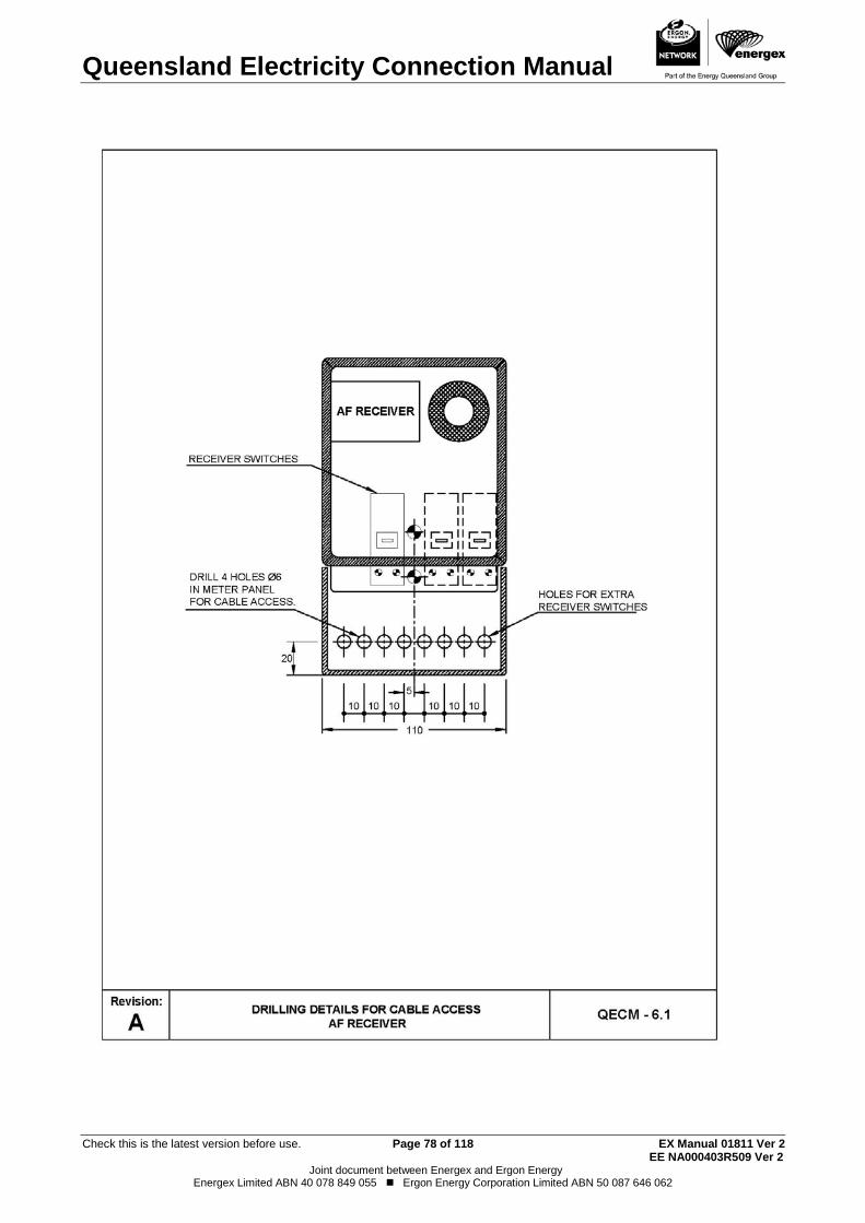
Queensland Electricity Connection Manual
Check this is the latest version before use. Page 78 of 118 EX Manual 01811 Ver 2 EE NA000403R509 Ver 2
Joint document between Energex and Ergon Energy Energex Limited ABN 40 078 849 055 Ergon Energy Corporation Limited ABN 50 087 646 062
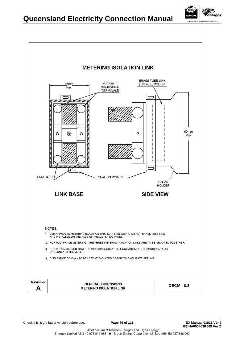
Queensland Electricity Connection Manual
Check this is the latest version before use. Page 79 of 118 EX Manual 01811 Ver 2 EE NA000403R509 Ver 2
Joint document between Energex and Ergon Energy Energex Limited ABN 40 078 849 055 Ergon Energy Corporation Limited ABN 50 087 646 062
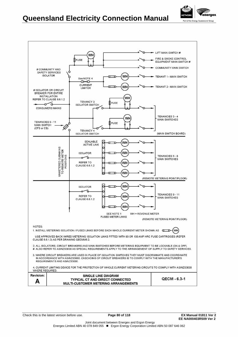
Queensland Electricity Connection Manual
Check this is the latest version before use. Page 80 of 118 EX Manual 01811 Ver 2 EE NA000403R509 Ver 2
Joint document between Energex and Ergon Energy Energex Limited ABN 40 078 849 055 Ergon Energy Corporation Limited ABN 50 087 646 062

Queensland Electricity Connection Manual
Check this is the latest version before use. Page 81 of 118 EX Manual 01811 Ver 2 EE NA000403R509 Ver 2
Joint document between Energex and Ergon Energy Energex Limited ABN 40 078 849 055 Ergon Energy Corporation Limited ABN 50 087 646 062
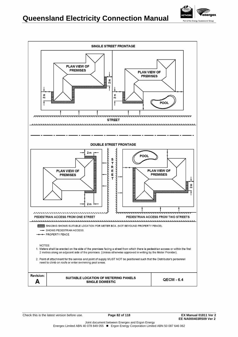
Queensland Electricity Connection Manual
Check this is the latest version before use. Page 82 of 118 EX Manual 01811 Ver 2 EE NA000403R509 Ver 2
Joint document between Energex and Ergon Energy Energex Limited ABN 40 078 849 055 Ergon Energy Corporation Limited ABN 50 087 646 062
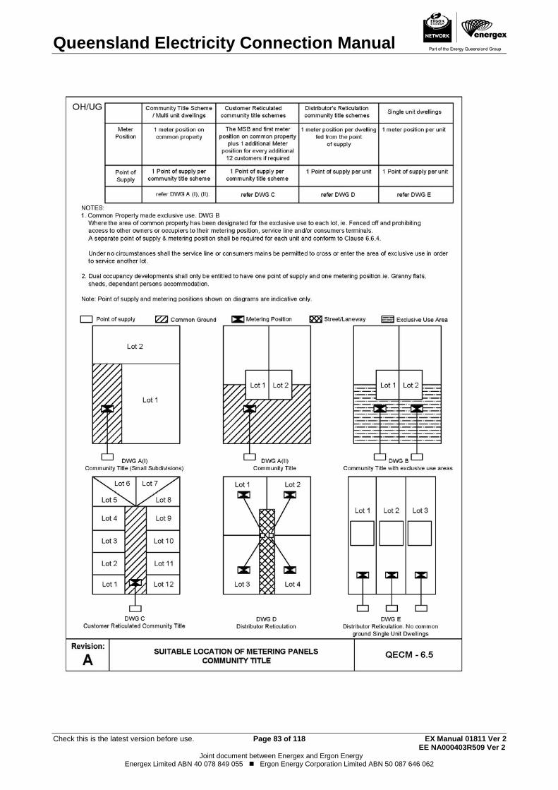
Queensland Electricity Connection Manual
Check this is the latest version before use. Page 83 of 118 EX Manual 01811 Ver 2 EE NA000403R509 Ver 2
Joint document between Energex and Ergon Energy Energex Limited ABN 40 078 849 055 Ergon Energy Corporation Limited ABN 50 087 646 062
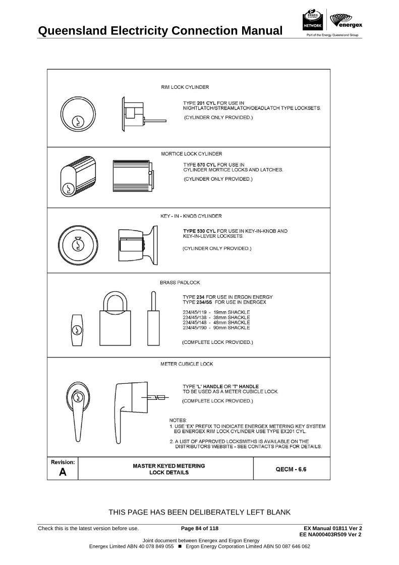
Queensland Electricity Connection Manual
Check this is the latest version before use. Page 84 of 118 EX Manual 01811 Ver 2 EE NA000403R509 Ver 2
Joint document between Energex and Ergon Energy Energex Limited ABN 40 078 849 055 Ergon Energy Corporation Limited ABN 50 087 646 062
THIS PAGE HAS BEEN DELIBERATELY LEFT BLANK
Queensland Electricity Connection Manual
Check this is the latest version before use. Page 85 of 118 EX Manual 01811 Ver 2 EE NA000403R509 Ver 2
Joint document between Energex and Ergon Energy Energex Limited ABN 40 078 849 055 Ergon Energy Corporation Limited ABN 50 087 646 062
Queensland Electricity Connection Manual
Check this is the latest version before use. Page 86 of 118 EX Manual 01811 Ver 2 EE NA000403R509 Ver 2
Joint document between Energex and Ergon Energy Energex Limited ABN 40 078 849 055 Ergon Energy Corporation Limited ABN 50 087 646 062
7. CONTROLLED SUPPLIES - METHOD OF CONTROL General 7.1.
For controlled supplies, the distributor will supply a network device.
Two and three switch network devices will be utilised for the following situations:
(a) For single installations where a combination of water heating and other controlled loads are connected. (Refer to Drawings QECM 7.1, 7.3, 7.5, 7.6 and 7.7). (b) For multiple installations, such as flats and home units. (Refer to Drawing QECM7.4)
The electrical contractor shall install all network device wiring. The electrical contractor shall install all meter wiring unless an agreement has been negotiated with the metering provider.
Equipment connected to a controlled supply is to be permanently connected however specific equipment may be connected via a socket outlet at the distributor’s discretion (refer to Frequently Asked Questions document in Technical Documents Section of distributor’s website). Where a socket outlet is provided for this purpose, it shall be dedicated to the controlled supply equipment (spare controlled supply outlets are not permitted). A permanent indelible label shall be fixed on or adjacent to the socket outlet stating the following:
Network Devices 7.2. Where equipment other than water heating, is to be connected to a 7.2.1
controlled supply, this equipment is to be connected via a dedicated circuit and connected to a dedicated switch in a multi-switch network device.
Note: On existing installations where submains are installed from the main
switchboard/metering point to a distribution switchboard other equipment can be connected to the controlled supply, however, it will be switched at the same time as the hot water supply. This shall only be permitted provided the main switchboard/metering point and distribution switchboard are not located within close proximity (within 20 meters) or back to back with each other.
Single phase installations with controlled supplies shall be connected in 7.2.2accordance with Drawings QECM 7.1 - 7.3
Multiple installations where multi-switch network devices are utilised must be 7.2.3provided with a network device switch per customer in accordance with Drawing QECM 7.4. Switching of individual customer’s hot water by the use of contactors is not permitted.
Notes: 1. Connections to multi-switch network devices shall be clearly labelled to
identify the switch applicable to each customer.
2. A separate metering isolation link is to be used for supply to the network device(s). Where more than one switch per customer is required then an individual network device per customer shall be used as per Clause 7.2.2.
Controlled Supply Only
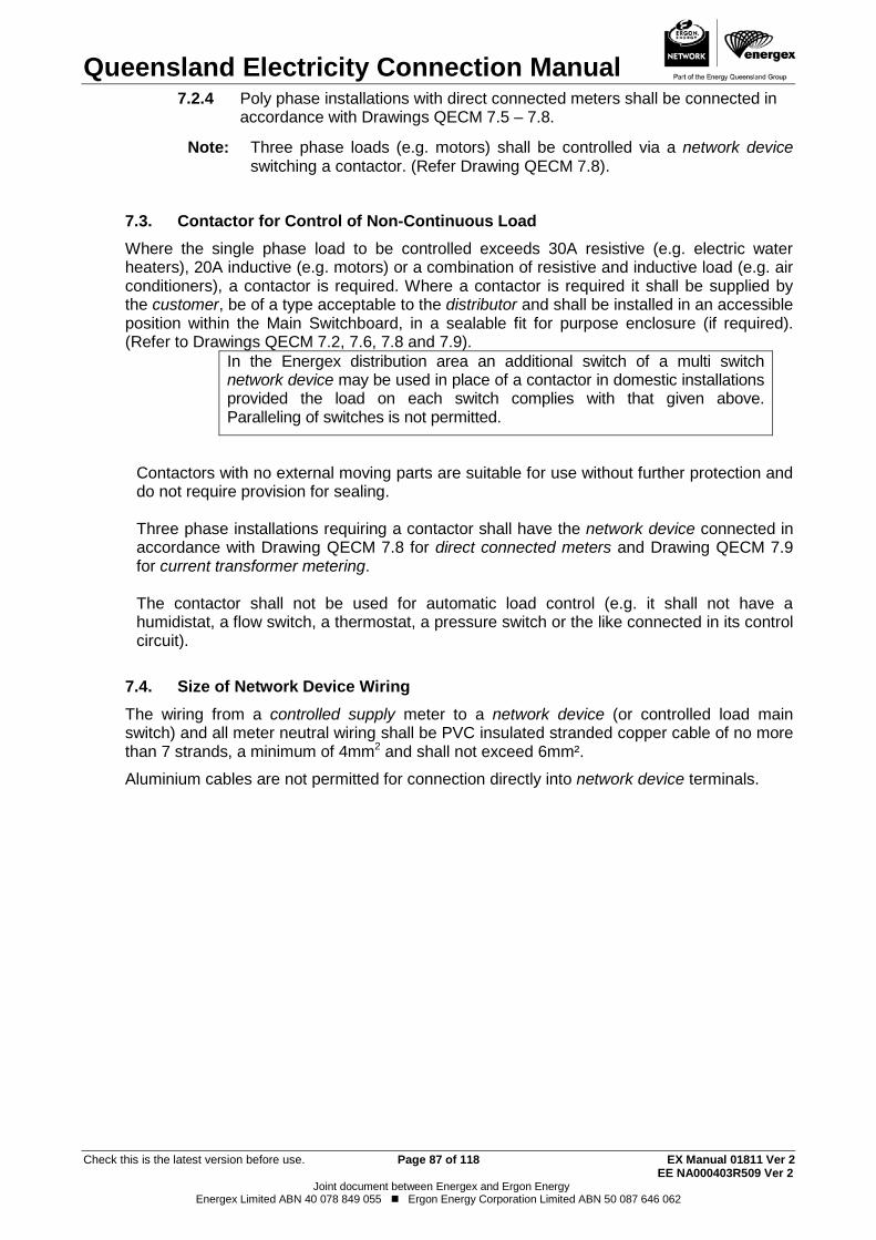
Queensland Electricity Connection Manual
Check this is the latest version before use. Page 87 of 118 EX Manual 01811 Ver 2 EE NA000403R509 Ver 2
Joint document between Energex and Ergon Energy Energex Limited ABN 40 078 849 055 Ergon Energy Corporation Limited ABN 50 087 646 062
Poly phase installations with direct connected meters shall be connected in 7.2.4accordance with Drawings QECM 7.5 – 7.8.
Note: Three phase loads (e.g. motors) shall be controlled via a network device switching a contactor. (Refer Drawing QECM 7.8).
Contactor for Control of Non-Continuous Load 7.3.Where the single phase load to be controlled exceeds 30A resistive (e.g. electric water heaters), 20A inductive (e.g. motors) or a combination of resistive and inductive load (e.g. air conditioners), a contactor is required. Where a contactor is required it shall be supplied by the customer, be of a type acceptable to the distributor and shall be installed in an accessible position within the Main Switchboard, in a sealable fit for purpose enclosure (if required). (Refer to Drawings QECM 7.2, 7.6, 7.8 and 7.9).
In the Energex distribution area an additional switch of a multi switch network device may be used in place of a contactor in domestic installations provided the load on each switch complies with that given above. Paralleling of switches is not permitted.
Contactors with no external moving parts are suitable for use without further protection and do not require provision for sealing. Three phase installations requiring a contactor shall have the network device connected in accordance with Drawing QECM 7.8 for direct connected meters and Drawing QECM 7.9 for current transformer metering. The contactor shall not be used for automatic load control (e.g. it shall not have a humidistat, a flow switch, a thermostat, a pressure switch or the like connected in its control circuit).
Size of Network Device Wiring 7.4.The wiring from a controlled supply meter to a network device (or controlled load main switch) and all meter neutral wiring shall be PVC insulated stranded copper cable of no more than 7 strands, a minimum of 4mm2 and shall not exceed 6mm².
Aluminium cables are not permitted for connection directly into network device terminals.

Queensland Electricity Connection Manual
Check this is the latest version before use. Page 88 of 118 EX Manual 01811 Ver 2 EE NA000403R509 Ver 2
Joint document between Energex and Ergon Energy Energex Limited ABN 40 078 849 055 Ergon Energy Corporation Limited ABN 50 087 646 062
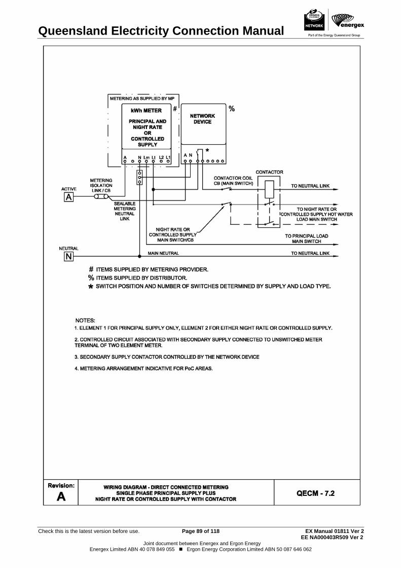
Queensland Electricity Connection Manual
Check this is the latest version before use. Page 89 of 118 EX Manual 01811 Ver 2 EE NA000403R509 Ver 2
Joint document between Energex and Ergon Energy Energex Limited ABN 40 078 849 055 Ergon Energy Corporation Limited ABN 50 087 646 062
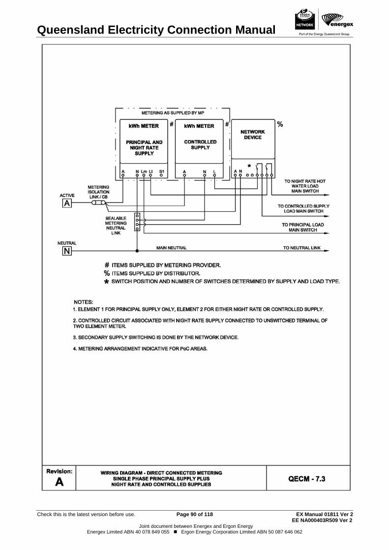
Queensland Electricity Connection Manual
Check this is the latest version before use. Page 90 of 118 EX Manual 01811 Ver 2 EE NA000403R509 Ver 2
Joint document between Energex and Ergon Energy Energex Limited ABN 40 078 849 055 Ergon Energy Corporation Limited ABN 50 087 646 062
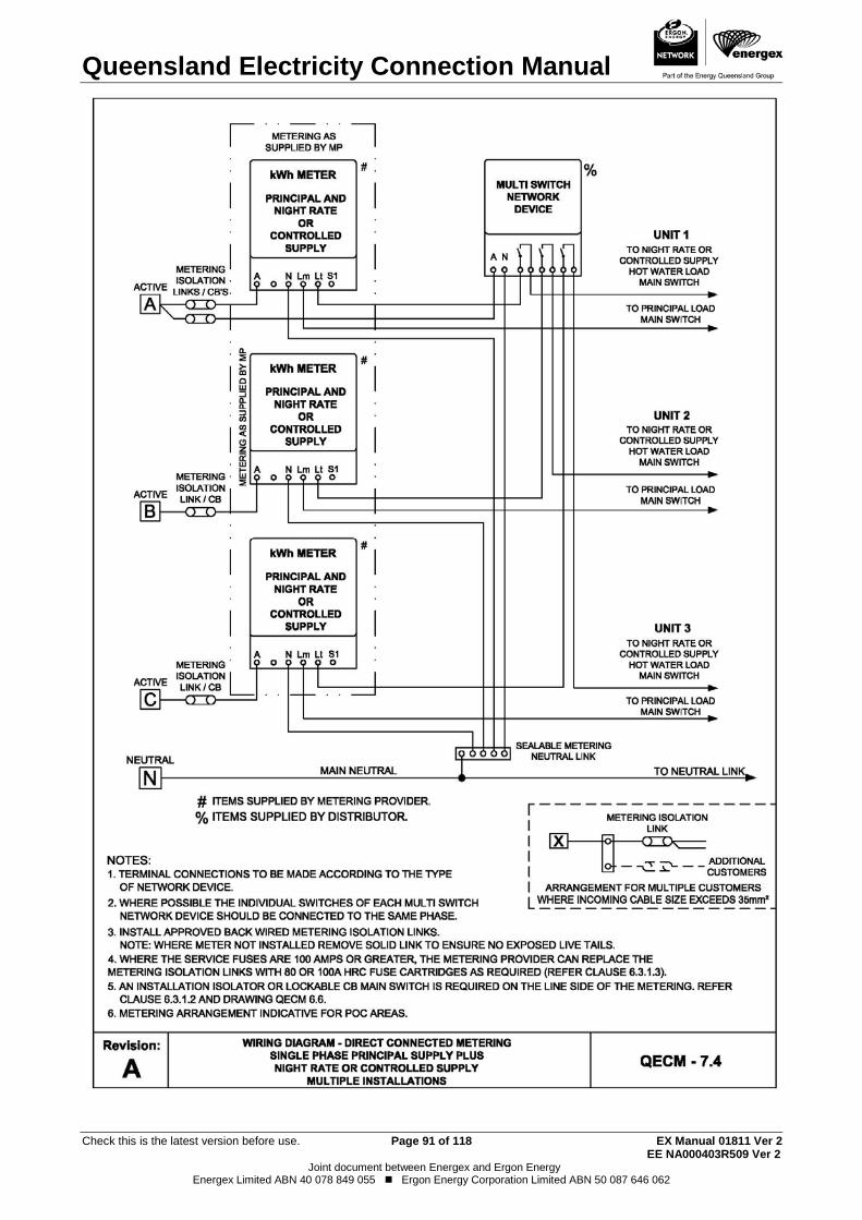
Queensland Electricity Connection Manual
Check this is the latest version before use. Page 91 of 118 EX Manual 01811 Ver 2 EE NA000403R509 Ver 2
Joint document between Energex and Ergon Energy Energex Limited ABN 40 078 849 055 Ergon Energy Corporation Limited ABN 50 087 646 062
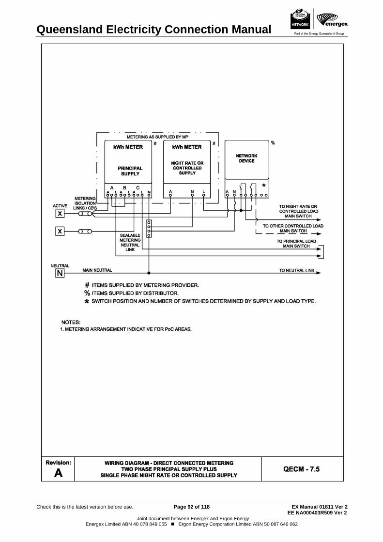
Queensland Electricity Connection Manual
Check this is the latest version before use. Page 92 of 118 EX Manual 01811 Ver 2 EE NA000403R509 Ver 2
Joint document between Energex and Ergon Energy Energex Limited ABN 40 078 849 055 Ergon Energy Corporation Limited ABN 50 087 646 062
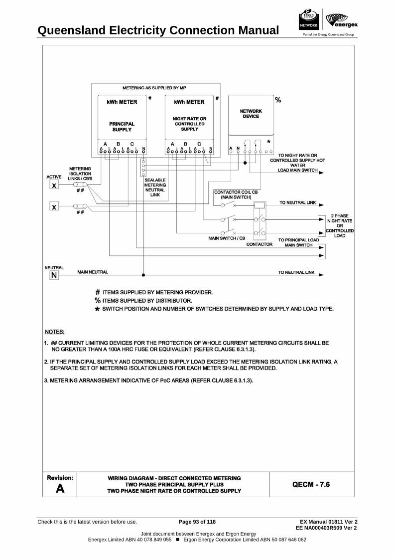
Queensland Electricity Connection Manual
Check this is the latest version before use. Page 93 of 118 EX Manual 01811 Ver 2 EE NA000403R509 Ver 2
Joint document between Energex and Ergon Energy Energex Limited ABN 40 078 849 055 Ergon Energy Corporation Limited ABN 50 087 646 062
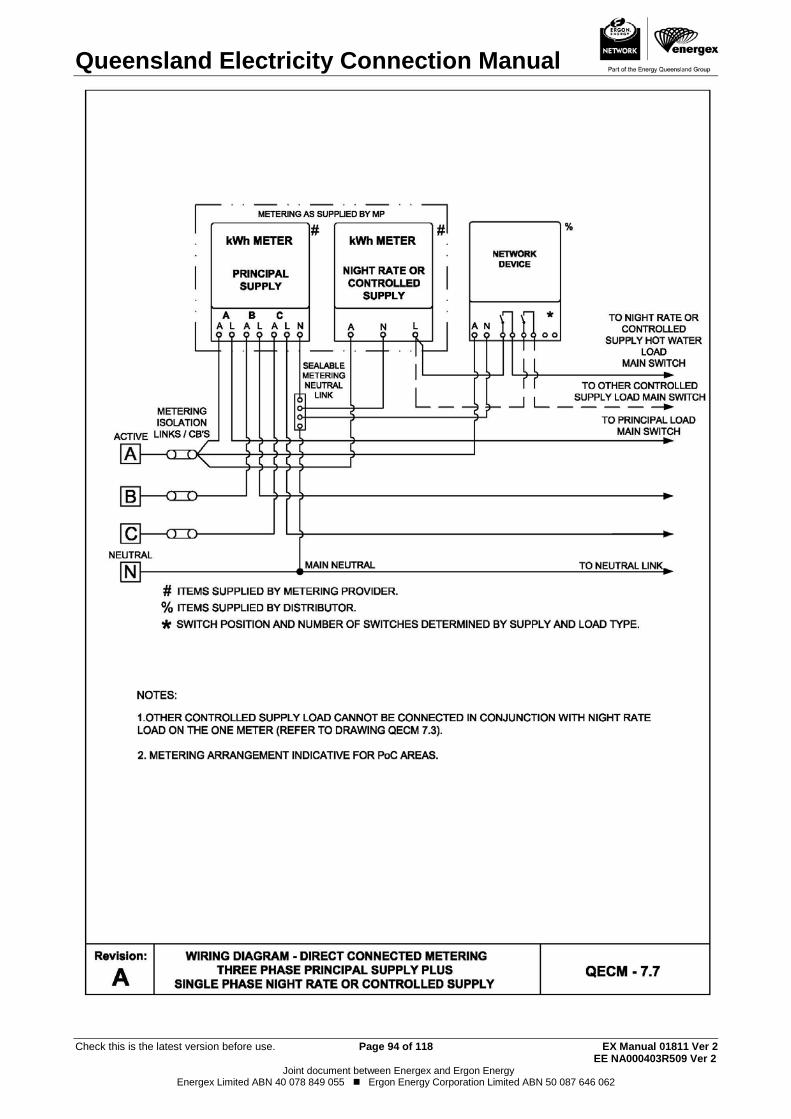
Queensland Electricity Connection Manual
Check this is the latest version before use. Page 94 of 118 EX Manual 01811 Ver 2 EE NA000403R509 Ver 2
Joint document between Energex and Ergon Energy Energex Limited ABN 40 078 849 055 Ergon Energy Corporation Limited ABN 50 087 646 062
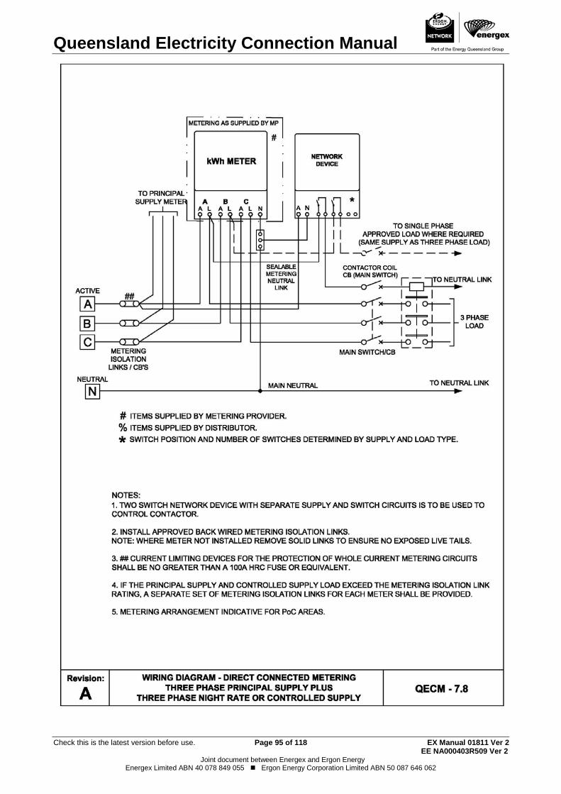
Queensland Electricity Connection Manual
Check this is the latest version before use. Page 95 of 118 EX Manual 01811 Ver 2 EE NA000403R509 Ver 2
Joint document between Energex and Ergon Energy Energex Limited ABN 40 078 849 055 Ergon Energy Corporation Limited ABN 50 087 646 062
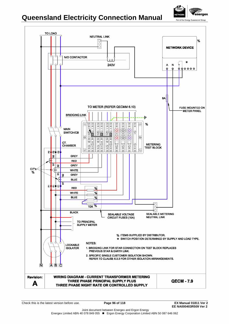
Queensland Electricity Connection Manual
Check this is the latest version before use. Page 96 of 118 EX Manual 01811 Ver 2 EE NA000403R509 Ver 2
Joint document between Energex and Ergon Energy Energex Limited ABN 40 078 849 055 Ergon Energy Corporation Limited ABN 50 087 646 062

Queensland Electricity Connection Manual
Check this is the latest version before use. Page 97 of 118 EX Manual 01811 Ver 2 EE NA000403R509 Ver 2
Joint document between Energex and Ergon Energy Energex Limited ABN 40 078 849 055 Ergon Energy Corporation Limited ABN 50 087 646 062
THIS PAGE HAS BEEN DELIBERATELY LEFT BLANK
Queensland Electricity Connection Manual
Check this is the latest version before use. Page 98 of 118 EX Manual 01811 Ver 2 EE NA000403R509 Ver 2
Joint document between Energex and Ergon Energy Energex Limited ABN 40 078 849 055 Ergon Energy Corporation Limited ABN 50 087 646 062
8. ARRANGEMENTS FOR EMBEDDED GENERATING SYSTEMS CONNECTED TO THE DISTRIBUTION NETWORK
Explanation of Metering Schemes Available 8.1.Two metering schemes are available for the grid-connected Embedded Generating (EG) systems, known as the “Net Energy” and the “Gross Energy” schemes. All EG systems installations must be compliant with the distributor’s connection standards.
The Queensland Government Solar Bonus Scheme requires the installation of a Net Energy metering solution.
The Net Energy metering scheme has a single import/export meter installed in the place of the existing general supply energy consumption meter(s).
The Gross Energy metering scheme may require an additional import/ export meter installed on the meter panel to record the EG system supply energy generation only.
Agreements 8.2.All customers with an EG system must have an Network Connection Agreement for the EG system in place with the distributor before the EG system can be connected to the distributor’s supply network. This includes systems that are configured as minimal-export or non-export back to the distribution network.
The customer or their agent shall nominate the metering scheme on the application form for network connection of an EG system, and the electrical contractor shall nominate the metering scheme on their Electrical Work Request sent to the distributor. Customers wishing to be compensated for any electricity exported by the EG system to the distributor’s supply network other than through the Queensland Government Solar Bonus Scheme must also have a Power Purchase Agreement in place with their retailer. Details on determining eligibility for the Queensland Government Solar Bonus Scheme can be found at the Queensland Government website https://www.qld.gov.au/housing/buying-owning-home/feed-in-tariffs.
Approval of Equipment 8.3.Typical direct connected metering arrangements have been developed in line with EG system requirements and retailer offered supply types however it is up to the metering provider to install suitable metering arrangement to meet site requirements
For the “Net Energy Scheme” Drawings QEMM 7.1 to 7.8 cover typical single and polyphase supply/service connections for single and polyphase EG systems.
For the “Gross Energy Scheme” Drawings QEMM 8.1 and 8.2 cover typical single and three phase supply/service connections for single and polyphase EG systems.
Notes: 1. Exceptions to the above standards may be approved upon receipt of a written
application in exceptional circumstances. Applications shall be made in writing to the distributor. Standard charges will apply for such arrangements.
2. It must be noted that the “Gross Scheme” may require an additional meter, and the end user must be made aware that provision of this space is required at the current metering location.
3. In a “Net Scheme”, if the principal metering has more than one phase, it is a requirement that a polyphase meter must be used.
Queensland Electricity Connection Manual
Check this is the latest version before use. Page 99 of 118 EX Manual 01811 Ver 2 EE NA000403R509 Ver 2
Joint document between Energex and Ergon Energy Energex Limited ABN 40 078 849 055 Ergon Energy Corporation Limited ABN 50 087 646 062
Connection Requirements for EG Systems 8.4.Connection requirements associated with EG systems connected to the distribution network shall be in accordance with:
Total Inverter Rating (kVA) Energex Ergon Energy Up to and including 30kVA STD01143 STNW1170
Greater than 30 kW to 1,500 kW where connection point with distributor is at low voltage (LV)
STD01618 STNW1174
Greater than 30 kW and less than 5MW where connection point with distributor is at high voltage (HV)
STNW1175 STNW1175
Any EVSE installation capable of export to the grid (i.e. vehicle to grid) will be treated as an EG system.
Labelling Requirements to AS/NZS 4777.1 8.5.For installations sized 200 kVA and less, installation shall be compliant with the labelling requirements of AS/NZS 4777.1.

Queensland Electricity Connection Manual
Check this is the latest version before use. Page 100 of 118 EX Manual 01811 Ver 2 EE NA000403R509 Ver 2
Joint document between Energex and Ergon Energy Energex Limited ABN 40 078 849 055 Ergon Energy Corporation Limited ABN 50 087 646 062
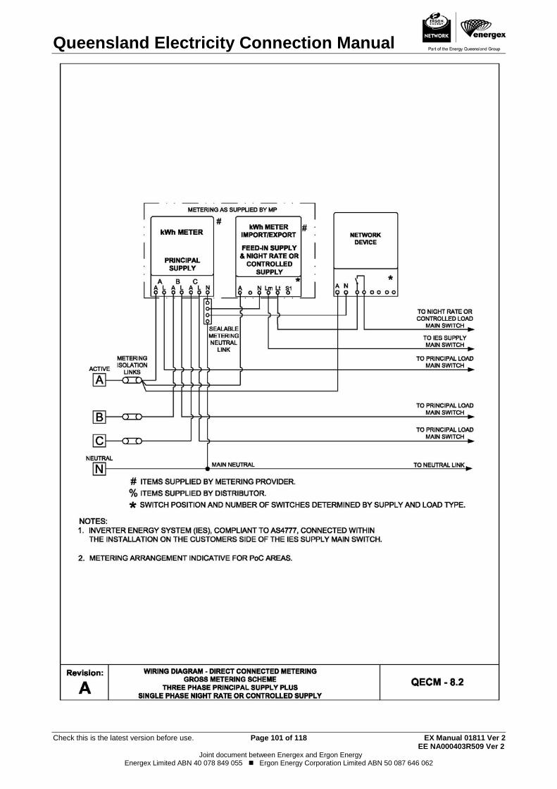
Queensland Electricity Connection Manual
Check this is the latest version before use. Page 101 of 118 EX Manual 01811 Ver 2 EE NA000403R509 Ver 2
Joint document between Energex and Ergon Energy Energex Limited ABN 40 078 849 055 Ergon Energy Corporation Limited ABN 50 087 646 062
Queensland Electricity Connection Manual
Check this is the latest version before use. Page 102 of 118 EX Manual 01811 Ver 2 EE NA000403R509 Ver 2
Joint document between Energex and Ergon Energy Energex Limited ABN 40 078 849 055 Ergon Energy Corporation Limited ABN 50 087 646 062
9. HIGH VOLTAGE METERING General Requirements 9.1.
The customer is required to supply, install and maintain all electrical equipment supplied by the customer. All high voltage equipment must be compatible with the distributor’s supply. Relays, current transformers and other protective equipment must have characteristics compatible with the distributor’s existing protective system.
The design, construction and installation of all high voltage equipment shall comply with the appropriate Australian Standards (e.g. AS/NZS 3000 (Wiring Rules) and AS 2067) or other equivalent Standards (e.g. IEC Standards). Plans, drawings and particulars describing the proposed installation and its operating conditions shall be provided.
The distributor will advise the customer of the prospective fault level and the normal fluctuations of supply voltage for which provisions should be made.
Testing Requirements 9.2.The customer shall meet the cost of any high voltage testing as required by AS 2067 and auditing in accordance with the Electrical Safety Act 2002.
The metering coordinator shall ensure that high voltage revenue metering instrument transformers are tested and maintained in accordance with the National Electricity Rules.
Operation of High Voltage Equipment 9.3.The customer is responsible for ensuring that the high voltage installation is operated in accordance with the requirements of the Electrical Safety Act 2002, the Electrical Safety Regulation 2013 and the Code of Practice for Electrical Work.
The customer has an obligation to ensure all persons who are involved in the high voltage isolation and access procedures have been trained and assessed as competent to perform the roles for which they are responsible.
Testing, earthing and safety equipment suitable for operation of the high voltage equipment shall be readily available on site.
For high voltage installations consisting of more than one item of switchgear, an operating diagram in the form of a single line schematic of the complete installation is to be permanently displayed adjacent to the main switch or switches.
Where items of switchgear are remote from the main switchboard, it is recommended that the operating diagram also be permanently displayed at these locations.
Maintenance and Repairs of High Voltage Equipment 9.4.A customer who takes supply at high voltage shall ensure that the high voltage installation is maintained so that any malfunction will not create a hazard or cause interference to the distributor’s supply.
All costs associated with the maintenance or repairs of the customer's high voltage installation shall be met by the customer.
Note: The customer must be prepared for power interruptions during high voltage testing procedures, maintenance or repairs.
Conversion from Low Voltage Supply to High Voltage Supply 9.5.A customer planning to convert from supply at low voltage to supply at high voltage shall negotiate with the distributor before commencement of work.
Options to be considered may include the following:
(a) Replacement of the distributor’s substation and other assets or purchase of this equipment from the distributor; and
Queensland Electricity Connection Manual
Check this is the latest version before use. Page 103 of 118 EX Manual 01811 Ver 2 EE NA000403R509 Ver 2
Joint document between Energex and Ergon Energy Energex Limited ABN 40 078 849 055 Ergon Energy Corporation Limited ABN 50 087 646 062
(b) Any costs associated with converting the installation for compliance with AS/NZS 3000 (Wiring Rules) and AS 2067.
Metering Requirements 9.6.The customer or customer’s representative (electrical contractor or consultant) must contact the distributor prior to commencing any project that may require high voltage metering. High voltage metering is complex and the following may need to be considered:
(a) Specialised metering design (voltage change-over schemes etc.).
(b) Compliance with the National Electricity Rules.
(c) Equipment with long lead times (e.g. 6 to 12 months) may be required.
(d) Full or partial check metering requirements for large loads.
(e) Generator connections and import/export load flows.
(f) Test certificates for metering instrument transformers from an accredited laboratory.
The relevant metering requirements in previous chapters also apply to high voltage installations. Where there are differences between the information in Section 9 and the remainder of the QECM, the requirements of Section 9 prevail in relation to high voltage metering. The additional details contained in Section 9 are specific to high voltage metering installations. The distributor or metering provider can be contacted for additional information.
Establishing a Network Connection and NMI 9.7.For high voltage connections the process of metering the site, data collection and settlement of energy requires the following steps:
1. The customer is required to engage an electricity retailer licensed to operate in Queensland.
2. The retailer is required to appoint a metering coordinator.
3. The metering coordinator is required to appoint the metering data provider and the provider.
4. The retailer is required to submit a SOR to the distributor to make the network connection.
The above process will establish a NMI per connection point in line with the distributor’s policies and the AEMO “National Metering Identifier Procedure” (refer to Flowchart 7 – Initial Connection – High Voltage Installation in Responsibilities Section).
Offer of Supply Letter and/or Network Connection Agreement 9.8.The distributor will negotiate a connection agreement detailing the conditions for the high voltage supply. This correspondence will include network requirements and the responsibility for providing the high voltage metering.
Connection point 9.9.Refer to Clause 5.2.2 for connection point arrangements.
The revenue metering point shall be located as close as practicable to the connection point.
Queensland Electricity Connection Manual
Check this is the latest version before use. Page 104 of 118 EX Manual 01811 Ver 2 EE NA000403R509 Ver 2
Joint document between Energex and Ergon Energy Energex Limited ABN 40 078 849 055 Ergon Energy Corporation Limited ABN 50 087 646 062
Revenue Metering 9.10.The arrangement for the high voltage revenue metering installation will be determined during the connection enquiry and application process: (a) A Type 1-3 metering installation; as required for HV connections is an
unregulated distribution service in Queensland and the customer is responsible for supplying, installing, maintaining and testing the metering installation including the instrument transformers.
(b) The metering installation contains the metering current transformers and the metering voltage transformers (revenue metering instrument transformers). Wherever practicable this equipment shall be located within the customer’s installation and be accessible to the metering provider. The metering installation shall comply with the requirements outlined in the AEMO Metrology Procedure Part A and the National Electricity Rules Chapter 7 and be approved by the metering coordinator.
(c) The customer shall provide revenue metering instrument transformers, associated equipment and plant. The equipment must be ready for the nominated metering provider to connect metering and communication equipment.
(d) Revenue metering instrument transformers will remain the customer’s property, and the customer will be responsible for maintaining, servicing and if failure occurs, replacing the metering instrument transformers in accordance with the requirements of the National Electricity Rules.
Note: Any fault or defect is required to be rectified within 2 business days or the metering coordinator must obtain an exemption from AEMO.
(e) The revenue metering instrument transformers are to be specified, installed, tested and maintained in accordance with the requirements of the National Electricity Rules, relevant Australian Standards (AS/NZS 3000 (Wiring Rules), AS 2067, AS 1243, AS 60044 series) and the QECM
(f) Instrument Transformer test certificates in accordance with the requirements of the National Electricity Rules Schedules 7.2 and 7.3 shall be provided to the metering provider prior to installation of the equipment.
i) Where revenue metering instrument transformers are tested in Australia, endorsed reports from a laboratory accredited by NATA are required; or
ii) Where revenue metering instrument transformers are tested overseas, endorsed reports from a laboratory accredited by an organisation recognised by ILAC (International Laboratory Accreditation Cooperation) are required.
(g) Metering installation designs that are approved by a metering provider or metering coordinator shall also be provided to the distributor prior to connection. The customer shall supply a single line diagram, HV switchboard layout, and a schematic diagram showing the wiring details from the instrument transformers (current and voltage transformers) to the metering panel.
(h) The customer is required to supply, install and test the secondary wiring and meter enclosure/panel and terminate the secondary wiring at the meter panel and the metering instrument transformers.
(i) The customer is responsible for ensuring that all requirements and steps in the metering installation process are coordinated in an efficient and timely manner to allow supply to be connected when required.
(j) The customer shall provide readily accessible high voltage test points on either side of the metering instrument transformers, in the
Queensland Electricity Connection Manual
Check this is the latest version before use. Page 105 of 118 EX Manual 01811 Ver 2 EE NA000403R509 Ver 2
Joint document between Energex and Ergon Energy Energex Limited ABN 40 078 849 055 Ergon Energy Corporation Limited ABN 50 087 646 062
specification/design of their switchgear. This will enable the metering provider to conduct the periodic high voltage metering instrument transformer accuracy tests (e.g. primary injection tests), required by the National Electricity Rules, with minimal power outages and disruption to the customer and their equipment.
(k) For metering installations greater than 1000 GWh pa per connection point, the current transformer core and secondary wiring associated with the meter(s) shall not be used for any other purpose unless otherwise agreed by AEMO.
(l) For metering installations less than 1000 GWh pa per connection point the current transformer core and secondary wiring associated with the meter(s) may be used for other purposes (e.g. local metering or protection) provided the metering coordinator demonstrates to the satisfaction of AEMO that the accuracy of the metering installation is not compromised and suitable procedures/measures are in place to protect the security of the metering installation.
(m) The metering voltage instrument transformers may be used to supply customers metering at the discretion and approval of the metering provider on a case by case basis. The secondary voltage supply from the voltage transformers will be separately fused with fuses located in an accessible position as near as practicable to the voltage transformer secondary connection. The revenue metering instrument transformers’ secondary wiring is to be earthed at one point only in accordance with the metering provider’s requirements.
(n) The minimum spacing between the meter wiring and other current carrying conductors shall comply with QEMM
(o) Adequate and safe access must be provided for the installation, routine and corrective maintenance of revenue metering equipment in accordance with AEMO requirements.
Meter Enclosure 9.11.The following requirements apply to high voltage metering enclosures:
(a) Unless otherwise detailed in the supply agreement the customer must supply a pre-wired meter panel and enclosure to the requirements of the metering provider. Wiring diagrams can be obtained from the metering provider.
(b) Any metering enclosure mounted externally must have an appropriate IP rating and be positioned so that adequate mechanical protection is provided.
(c) A hinged panel with minimum dimensions of 600mm x 600mm is required for the mounting of meters and metering test block on the same vertical surface.
(d) A metering enclosure installed on a pole in association with a distributor owned metering unit, will be supplied and maintained by the distributor.
(e) No customer owned equipment is to be installed within the metering provider’s dedicated metering enclosure.
(f) The supply and wiring of the meter panel may be carried out by the metering provider as part of a negotiated agreement.
(g) The customer is responsible for earthing of the metering enclosure in accordance with relevant standards and practices including consideration for earth potential rise.
(h) The customer should consider providing lockable front meter doors in locations where security may be an issue.
Queensland Electricity Connection Manual
Check this is the latest version before use. Page 106 of 118 EX Manual 01811 Ver 2 EE NA000403R509 Ver 2
Joint document between Energex and Ergon Energy Energex Limited ABN 40 078 849 055 Ergon Energy Corporation Limited ABN 50 087 646 062
Secondary Wiring 9.12.The following requirements apply to metering units supplied by the metering provider and revenue metering instrument transformers owned and installed by the customer.
(a) The customer shall supply and install the secondary wiring between the revenue metering instrument transformers and the test block or terminal strip.
(b) Revenue metering instrument transformer secondary wiring is to follow the most direct route and the number of terminations and links must be kept to a minimum.
(c) Revenue metering instrument transformer secondary wiring is to be PVC insulated stranded cable of no more than 7 strands.
(d) The secondary wiring shall be sized to ensure that the burden on the revenue metering instrument transformers is not exceeded.
(e) All taps of multi-tap CTs to be brought out to the marshalling box or metering enclosure (in the absence of a marshalling box).
(f) Any connection point in the revenue metering instrument transformers’ secondary circuit (terminals, links, fuses etc.) that is accessible must be identified as “Revenue Metering” and must be able to be covered and sealed.

Queensland Electricity Connection Manual
Check this is the latest version before use. Page 107 of 118 EX Manual 01811 Ver 2 EE NA000403R509 Ver 2
Joint document between Energex and Ergon Energy Energex Limited ABN 40 078 849 055 Ergon Energy Corporation Limited ABN 50 087 646 062
THIS PAGE HAS BEEN DELIBERATELY LEFT BLANK
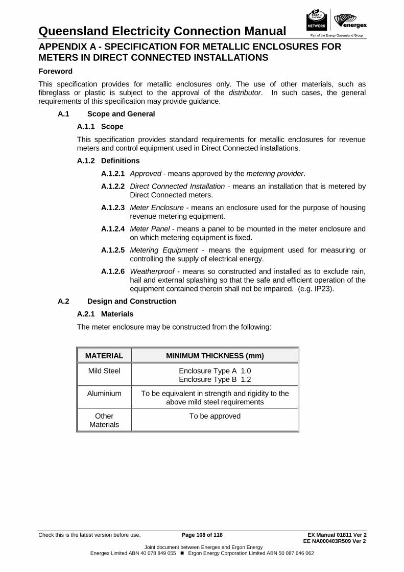
Queensland Electricity Connection Manual
Check this is the latest version before use. Page 108 of 118 EX Manual 01811 Ver 2 EE NA000403R509 Ver 2
Joint document between Energex and Ergon Energy Energex Limited ABN 40 078 849 055 Ergon Energy Corporation Limited ABN 50 087 646 062
APPENDIX A - SPECIFICATION FOR METALLIC ENCLOSURES FOR METERS IN DIRECT CONNECTED INSTALLATIONS Foreword This specification provides for metallic enclosures only. The use of other materials, such as fibreglass or plastic is subject to the approval of the distributor. In such cases, the general requirements of this specification may provide guidance.
A.1 Scope and General A.1.1 Scope This specification provides standard requirements for metallic enclosures for revenue meters and control equipment used in Direct Connected installations.
A.1.2 Definitions A.1.2.1 Approved - means approved by the metering provider.
A.1.2.2 Direct Connected Installation - means an installation that is metered by Direct Connected meters.
A.1.2.3 Meter Enclosure - means an enclosure used for the purpose of housing revenue metering equipment.
A.1.2.4 Meter Panel - means a panel to be mounted in the meter enclosure and on which metering equipment is fixed.
A.1.2.5 Metering Equipment - means the equipment used for measuring or controlling the supply of electrical energy.
A.1.2.6 Weatherproof - means so constructed and installed as to exclude rain, hail and external splashing so that the safe and efficient operation of the equipment contained therein shall not be impaired. (e.g. IP23).
A.2 Design and Construction A.2.1 Materials The meter enclosure may be constructed from the following:
MATERIAL MINIMUM THICKNESS (mm)
Mild Steel Enclosure Type A 1.0 Enclosure Type B 1.2
Aluminium To be equivalent in strength and rigidity to the above mild steel requirements
Other Materials
To be approved
Queensland Electricity Connection Manual
Check this is the latest version before use. Page 109 of 118 EX Manual 01811 Ver 2 EE NA000403R509 Ver 2
Joint document between Energex and Ergon Energy Energex Limited ABN 40 078 849 055 Ergon Energy Corporation Limited ABN 50 087 646 062
A.2.2 Construction A.2.2.1 The enclosure should be constructed free of burrs at the opening.
A.2.2.2 The enclosure, if of steel construction, shall be of galvanised or zincalume material and shall comply with the requirements of AS 1397 “Steel sheet and strip - hot dip zinc-coated or aluminium/zinc-coated”.
A galvanised steel meter enclosure shall have all galvanised surfaces repaired with a suitable zinc rich coating. All exterior surfaces of the enclosure should be painted with one coat of “etch primer”.
A.2.2.3 The use of aluminium shall be restricted to corrosion resistant alloys as recommended for the exposure to be encountered in service (stainless steel is an acceptable alternative).
A.2.2.4 Rivets shall be of a material that is compatible with the case material and must not react to set up points of corrosion.
A.2.2.5 Where additional mechanical strength is required stiffening ribs may be utilised. Such ribs must not in any way reduce the minimum internal dimensions.
A.2.3 Door A.2.3.1 The meter enclosure is to be fitted with a hinged door of sufficient
strength to prevent buckling or warping.
A.2.3.2 The door shall be side hinged, unless otherwise approved by the metering provider, and fitted with a suitable non-corroding chain or other approved means to limit the door travel to approximately 100 degrees. The door may be hinged at either the left or right side of the meter enclosure and shall be fitted with a simple self-latching device.
A.2.3.3 Hinges provided shall be of non-corroding material and so designed or fitted with non-corroding pins as to prevent seizing.
A.2.4 Door Latch The latching device provided shall engage automatically and hold the door firmly closed.
A.2.5 Entry of Wiring Adequate provisions shall be made for knockouts or slots for the entry of wiring to the meter enclosure. (Refer to AS/NZS 3000 (Wiring Rules) for fire protection requirements).
Entries may be provided in the top of the enclosure but in this case the final assembly should withstand the test in Appendix A Clause 2.7.
A.2.6 Earthing To ensure an effective Earth of the Switchboard Surround an earthing stud or terminal complying with the requirements of AS/NZS 3000 (Wiring Rules) shall be provided for the connection of an earthing conductor within the enclosure. The stud or terminal shall not obstruct equipment within the enclosure.
A.2.7 Weatherproofing The enclosure is to comply with AS/NZS 60529 "Degrees of Protection Provided by Enclosures" to a minimum of IP23.
The enclosure shall provide adequate ventilation to minimise condensation and be capable of draining any moisture that may collect within the enclosure.

Queensland Electricity Connection Manual
Check this is the latest version before use. Page 110 of 118 EX Manual 01811 Ver 2 EE NA000403R509 Ver 2
Joint document between Energex and Ergon Energy Energex Limited ABN 40 078 849 055 Ergon Energy Corporation Limited ABN 50 087 646 062
A.2.8 Meter Panel A.2.8.1 Meter panels shall be constructed of durable, non-conducting, fire
resistant material with low water absorption properties and shall not contain asbestos.
A.2.8.2 The meter panel shall be side hinged on a vertical axis so that the metering equipment always remains in the vertical plane.
A.2.8.3 Panel hinges should be of the double off-set type that allows for the panel to be swung into the fully opened position and shall be of adequate strength to support the meter panel, and associated metering equipment.
The hinges shall be constructed of a suitable non-corroding material. When the meter panel is opened at an angle of 90 degrees, the design of the enclosure and hinges should be such to withstand without undue distortion a weight of 25kg suspended vertically at a position 25mm from the outer edge of the panel.
A.3 Dimensions A.3.1 General Two basic types of meter enclosures are provided for, the dimensions of which are to be suitable for recessing into brick, block or framed walls. Other meter enclosures of adequate size to house the meters with recommended clearances and suitable construction may be used. The meter panel must meet the minimum size set out in the table below. This table is indicative of the most commonly supplied metering enclosures that comply with the QECM.
Metal Enclosure
Minimum Thickness Mild Steel
Minimum Space Required For
Metering Equipment
Clearance From
Back of Meter Panel to Back of Enclosure
Clearance From Back of Meter Panel to Inside of Door
Type A
Type B
1.0mm
1.2mm
480mm x 460mm
(high) (wide)
600mm x 550mm (high) (wide)
75mm
185mm

Queensland Electricity Connection Manual
Check this is the latest version before use. Page 111 of 118 EX Manual 01811 Ver 2 EE NA000403R509 Ver 2
Joint document between Energex and Ergon Energy Energex Limited ABN 40 078 849 055 Ergon Energy Corporation Limited ABN 50 087 646 062
THIS PAGE HAS BEEN DELIBERATELY LEFT BLANK.
Queensland Electricity Connection Manual
Check this is the latest version before use. Page 112 of 118 EX Manual 01811 Ver 2 EE NA000403R509 Ver 2
Joint document between Energex and Ergon Energy Energex Limited ABN 40 078 849 055 Ergon Energy Corporation Limited ABN 50 087 646 062
APPENDIX B - GLOSSARY OF TERMS Accredited Auditor A person appointed under section 129 of the Electrical Safety Act
2002 to audit high voltage or hazardous area installations before connection to supply. Further information may be obtained from the Electrical Safety Office.
AEMO ‘Australian Energy Market Operator’ is responsible for the day to day management of wholesale and retail energy market operations and emergency management protocols; on-going market development required to incorporate new rules, infrastructure and participants; and long term market planning through demand forecasting data and scenario analysis.
AF Receiver See “Network Device” Capital Contribution A contribution towards costs associated with a standard control
service, such as any necessary augmentation of connection assets at the connection point, dedicated network extension or augmentation of the shared distribution network to accommodate the connection/modification. A capital contribution will only be levied where there is a difference between the cost to provide the connection service and the revenue that will be earned by the distributor from the connection service.
Card Operated Meter A meter that contains control equipment that switches on and off in accordance with the amount of credit stored in the meter.
Common Property Common property means so much of a parcel as from time to time is not comprised in any lot. Building Units and Group Titles Act 1980
Connection Point
The agreed point of supply established between Network Service Provider(s) and another Registered Participant, Non-Registered Customer or franchise customer.
Note (1): AS/NZS 3000 refers to the ‘Connection Point’ as the ‘Point of Supply’. Previous editions of AS/NZS 3000 referred to the ‘Connection Point’ as the ‘consumer’s terminals’.
Note (2): The Queensland Electricity Regulation 2006 uses the definition ‘consumer’s terminals’.
Note (3): The National Electricity Rules uses the definition ‘connection point’.
Note (4): This is the point which differentiates the responsibilities of the Network Service Provider and the application of AS/NZS 3000.
Connection Policy
The distributor’s connection policy provides an outline of connection services, when connection charges may be payable by customers and how those charges are calculated.
Consumer’s Mains The conductors between the connection point and the main switchboard.
Consumer’s Terminals See connection point.
Queensland Electricity Connection Manual
Check this is the latest version before use. Page 113 of 118 EX Manual 01811 Ver 2 EE NA000403R509 Ver 2
Joint document between Energex and Ergon Energy Energex Limited ABN 40 078 849 055 Ergon Energy Corporation Limited ABN 50 087 646 062
Controlled Load, Controlled Supply
Those loads that are wired separately from other appliances, are controlled by means of frequency injection receiver or time clock, and are separately metered from the remaining load at the metering point.
Current Transformer Metering
A metering arrangement where electricity flow is measured by a meter using current transformers (CTs).
Customer A person, including a relevant body corporate, who receives, or wants to receive, a supply of electricity for a premises from an electricity entity or special approval holder.
Direct Connected Meter A meter where the electricity flow is directly measured by the meter i.e. the current under measurement passes through the meter itself.
Distribution Entity, Distributor
A distribution entity is a person who holds a distribution authority that authorises its holder to supply electricity using a supply network within its distribution area. See sections 37, 38 and 39 of the Queensland Electricity Act 1994. (Refer to definition for Relevant Distribution Entity).
EG system (s) One or more electricity generating units and auxiliary equipment that are interconnected with a distributor’s network.
Electrical Contractor (EC)
A person licensed under the Electrical Safety Act 2002 to conduct a business or undertaking that includes the performance of electrical work.
Electrical Work Request (EWR)
The request from the customer’s electrical contractor to a distributor to perform a distribution service e.g. (i) Energex - Form 2; or (ii) Ergon Energy - Form A - Request for Initial Connection, Metering
Change or Service Alteration
Energex Energex Limited - ABN 40 078 849 055
Enhanced Metering A scheme, which is not normally considered to be part of standard metering as described in this manual (e.g. has pulse inputs, outputs, or remote communications). Additions that are above and beyond the metering provided in this manual.
Ergon Energy Ergon Energy Corporation Limited ABN 50 087 646 062
EVSE Electric Vehicle Supply Equipment as defined in AS/IEC 62196
Excluded Customer A customer who cannot choose their retailer. For example, customers connected to isolated power systems.
Gross Energy Scheme The Gross Energy Scheme separately meters the full energy output of the Micro EG Unit. The energy consumed at the premises is metered normally.
High Voltage Metering A high voltage metering arrangement where electricity flow is
measured by a meter using current transformers and voltage transformers.
Queensland Electricity Connection Manual
Check this is the latest version before use. Page 114 of 118 EX Manual 01811 Ver 2 EE NA000403R509 Ver 2
Joint document between Energex and Ergon Energy Energex Limited ABN 40 078 849 055 Ergon Energy Corporation Limited ABN 50 087 646 062
Interconnected Connection of an EG system capable of parallel operation with a distributor’s netowrk.
Isolated Power System A supply network that does not form part of and is not connected to the national grid and may include an isolated feeder.
Large Customer A customer whose annual consumption is equal to, or greater than, 100MWh, and is connected to the distributor’s network.
Large Non-market Customer
A large non-market customer, for premises, is a large customer for the premises who is also a non-market customer for the premises.
Metering Coordinator A person who has been registered by AEMO under Chapter 2 of the
National Electricity Rules to engage in the coordination and provision of metering services at a connection point in accordance with Chapter 7 of the National Electricity Rules.
Metering Data Agent An agent appointed by AEMO to undertake the collection, processing and transfer of metering data to AEMO and other registered participants.
Metering Data Provider
A person who meets the requirements listed in schedule 7.3 of the National Electricity Rules and has been accredited and registered by AEMO to undertake the collection, processing, storage and delivery of metering data and the management of NMI Standing Data.
Metering Provider (MP) A person who meets the requirements listed in schedule 7.2 of the National Electricity Rules and has been accredited and registered by AEMO to undertake the provision, installation and maintenance of metering installations. Note: The distributor is the metering provider in non-NEM areas.
Micro EG Unit A grid connected Micro Embedded Generating Unit as defined in AS/NZS 4777.1.
NATA The National Association of Testing Authorities.
National Electricity Rules
The rules under which the National Electricity Market operates.
National Metering Identifier (NMI)
A National Metering Identifier (NMI) is a unique national identifier that relates to the metering installation at a customer’s premises.
Net Energy Scheme The Net Energy Scheme provides for the separate measurement of the energy supplied from the LV network to the customer’s installation in excess of the Micro EG Unit generation, and the excess energy supplied to the LV network from the premises by the Micro EG Unit after the energy needs at the premises are met.
Queensland Electricity Connection Manual
Check this is the latest version before use. Page 115 of 118 EX Manual 01811 Ver 2 EE NA000403R509 Ver 2
Joint document between Energex and Ergon Energy Energex Limited ABN 40 078 849 055 Ergon Energy Corporation Limited ABN 50 087 646 062
Network Device, AF Receiver
Apparatus or equipment that: (a) enables a distributor to monitor, operate or control the network for the purposes of providing network services, which may include switching devices, measurement equipment and control equipment; and (b) is located at or adjacent to a metering installation at the connection point of a customer.
NMI Classification Small - annual consumption less than 100MWh Large - annual consumption equal to, or greater than 100MWh.
Point of Attachment The point at which aerial conductors of a service line or aerial consumer’s mains are terminated on a customer’s structure.
Point of Entry The point at which the consumer’s mains or the underground service cable enters a structure.
Premises Premises includes - (a) a building or other structure; and (b) a part of a building or other structure; and (c) land where a building or other structure is situated. Premises, of a customer, means premises owned or occupied by the customer. Queensland Electricity Act 1994
QECM Queensland Electricity Connection Manual
QECMM Queensland Electricity Connection and Metering Manual. On 24th August 2018 the QECMM content was separated into two new documents, the QECM and the QEMM and the QECMM was withdrawn.
QEMM Queensland Electricity Metering Manual
Relevant Distribution Entity, Distributor
The relevant distribution entity for a premises, means the distribution entity to whose supply network the premises are, or will be, connected. Note: For the purposes of this document the relevant distribution
entity will be referred to as the ‘distributor’.
Relevant Retail Entity, Retailer
The relevant retail entity for a premise, means the retail entity who, under a retail contract, supplies or has agreed to supply electricity to the premises. Note: For the purposes of this document the relevant retail entity will
be referred to as the ‘retailer’.
Retail Entity A person who holds a retail authority to sell electricity and retail services (a ‘retail authority’ authorises its holder to provide customer retail services under the terms of the authority).
RPEQ Registered Professional Engineer Queensland.
Queensland Electricity Connection Manual
Check this is the latest version before use. Page 116 of 118 EX Manual 01811 Ver 2 EE NA000403R509 Ver 2
Joint document between Energex and Ergon Energy Energex Limited ABN 40 078 849 055 Ergon Energy Corporation Limited ABN 50 087 646 062
Rural/Isolated Area
A rural/Isolated area is defined as one with a density of less than 5 lots per hectare (i.e. would generally have a dedicated supply transformer). Note: This definition is only applicable within the Ergon Energy
distribution area.
Service Line An electric line that- (a) forms part of the works of an electricity entity; and (b) connects consumer terminals to - (i) other parts of the works of the electricity entity; or (ii) the works of another electricity entity. Schedule 9 of the Queensland Electricity Regulation 2006.
Small Customer A customer who consumes less than 100MWh per annum and is connected to the distributor’s network.
SOR
Service Order Request - This is a request from a Retailer to a Distributor to perform a distribution service (e.g. New Connections, Metering Alterations and Service Upgrades). It is also referred to as a B2B request.
Suitable Mains Connection Box
A mains connection box that is deemed to be compliant with the distributor’s technical specifications. Details are available by contacting the distributor via the methods listed on page 1
Two element Meter
A single phase two element device which includes both metering and load switching within one meter.
Type 1-7 Metering Installation
As defined in the National Electricity Rules
Unmetered Supply A Type 7 metering installation classification (NER) where a metering installation does not require a meter to measure the flow of electricity in a power conductor and accordingly there is a requirement to determine by other means the energy data that is deemed to flow in the power conductor and managed by the relevant Distribution Entity.
Urban A residential area with a system of street lighting.

Queensland Electricity Connection Manual
Check this is the latest version before use. Page 117 of 118 EX Manual 01811 Ver 2 EE NA000403R509 Ver 2
Joint document between Energex and Ergon Energy Energex Limited ABN 40 078 849 055 Ergon Energy Corporation Limited ABN 50 087 646 062
THIS PAGE HAS BEEN DELIBERATELY LEFT BLANK.
Queensland Electricity Connection Manual
Check this is the latest version before use. Page 118 of 118 EX Manual 01811 Ver 2 EE NA000403R509 Ver 2
Joint document between Energex and Ergon Energy Energex Limited ABN 40 078 849 055 Ergon Energy Corporation Limited ABN 50 087 646 062
APPENDIX C - AMENDMENT RECORD Please note: It is not possible to cover all of the changes in the following list, nor can the changes be covered in the detail and context as they appear within the manual. As an Electrical Contractor it is the responsibility of you and your endorsees to be fully conversant with the content and requirements of the Queensland Electricity Connection Manual. Date 24/08/18 Previous Version: Version 12 of the QECMM Version 1 update includes the separation of the metering component from this manual to the QEMM Additionally, clauses have been rearranged to group similar items together. Changes are extensive and have not been included in detail in this Appendix.