
QUALIFICATION EVALUATION OF THE TOWER … the apollo spacecraft program launch escape system by b,...
114
NASA . . .._ , . . . , . ._. TECHNICAL NOTE QUALIFICATION EVALUATION OF THE TOWERJETTISONMOTOR FOR THE APOLLO SPACECRAFT PROGRAM LAUNCH ESCAPE SYSTEM by B, J, Lee MannedSpacecraftCenter Hoaston, Texas 77058 NATIONAL AERONAUTICS AND SPACE ADMINISTRATION WASHINGTON, D. C. APRIL 1971 https://ntrs.nasa.gov/search.jsp?R=19710015557 2018-07-10T00:37:21+00:00Z
Transcript of QUALIFICATION EVALUATION OF THE TOWER … the apollo spacecraft program launch escape system by b,...
NASA
. . .._ , . . . , . ._ .
TECHNICAL NOTE
QUALIFICATION EVALUATION OF THE TOWER JETTISON MOTOR FOR THE APOLLO SPACECRAFT PROGRAM LAUNCH ESCAPE SYSTEM
by B, J , Lee
Manned Spacecraft Center Hoaston, Texas 77058
N A T I O N A L A E R O N A U T I C S A N D S P A C E A D M I N I S T R A T I O N W A S H I N G T O N , D. C. APRIL 1971
https://ntrs.nasa.gov/search.jsp?R=19710015557 2018-07-10T00:37:21+00:00Z
TECH LIBRARY KAFB, NM
.REPORT NO. 1 2 . GOVERNMENT ACCESSION NO. I 3. R E C I P I E N T ' S C A > n ~ v u I.". NASA TN &29.5 I I QUALIFICATION EVALUATION OF THE TOWER JETTISON MOTOR FOR THE APOLLO 6. PERFORMING ORGANIZATION CODE
SPACECRAFT PROGRAM LAUNCH ESCAPE SYSTEM
I. T I T L E AND S U B T I T L E 5. REPORT DATE I April 1971
B. J. Lee, MSC I MSC S-216
3 . PERFORMING ORGANIZATION NAME AND ADDRESS
Manned Spacecraft Center Houston, Texas 77058
10. WORK UNIT NO. I 914-50-60-01-72 I I I . CONTRACT OR GRANT NO.
I 12. SPONSORING AGENCY NAME AND ADDRESS 13. REPORT TYPE AND PERIOD COVERED
National Aeronautics and Space Administration I Technical Note Washington, D. C. 20546
14. SPONSORING AGENCY CODE
1
15. SUPPLEMENTARY NOTES
16. ABSTRACT
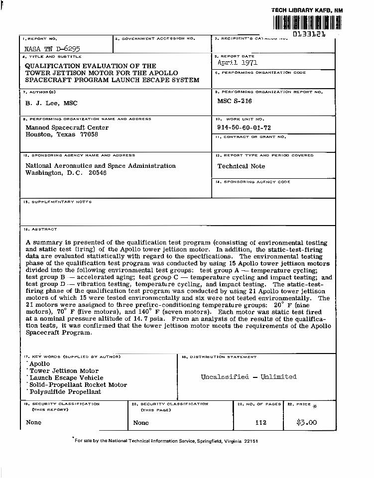
A summary is presented of the qualification test program (consisting of environmental testing and static test firing) of the Apollo tower jettison motor. In addition, the static-test-firing data are evaluated statistically with regard to the specifications. The environmental testing phase of the qualification test program was conducted by using 15 Apollo tower jettison motors divided into the following environmental test groups: test group A - temperature cycling; test group B - accelerated aging; test group C - temperature cycling and impact testing; and test group D - vibration testing, temperature cycling, and impact testing. The static-test- firing phase of the qualification test program was conducted by using 21 Apollo tower jettison motors of which 15 were tested environmentally and six were not tested environmentally. The 21 motors woere assigned to three prefire-conditioning temperature groups: 20" F (nine motors), 70 F (five motors), and 140 F (seven motors). Each motor was static test fired at a nominal pressure altitude of 14.7 psia. From an analysis of the results of the qualifica- tion tests, it was confirmed that the tower jettison motor meets the requirements of the Apollo Spacecraft Program.
17. KEY-WORDS (SUPPLIED B Y AUTHOR)
* Apollo ' Tower Jettison Motor ' Launch Escape Vehicle ' Solid-Propellant Rocket Motor ' Polysulfide Propellant
18. D ISTRIBUTION STATEMENT
Uncalssified - Unlimited
19. SECURITY CLASSIFICATION 22. PRICE 21. NO. OF PAGES 20. SECURITY CLASSIF ICATION
(THIS REPORT) W H I S PAGE) *
None $3 00 112 None
For sale by the National Technical Information Service, Springfield, Virginia 22151

CONTENTS
. Section
SUMMARY . . . . . . . . . . . . . . . . . . . . . . . . . . . . . . . . . . . . . INTRODUCTION . . . . . . . . . . . . . . . . . . . . . . . . . . . . . . . . . . SYMBOLS . . . . . . . . . . . . . . . . . . . . . . . . . . . . . . . . . . . . . TOWER JETTISON MOTOR DESCRIPTION . . . . . . . . . . . . . . . . . . . . ENVIRONMENTAL TESTING . . . . . . . . . . . . . . . . . . . . . . . . .
Temperature Cycling . . . . . . . . . . . . . . . . . . . . . . . . . . . . . . Accelerated Aging . . . . . . . . . . . . . . . . . . . . . . . . . . . . . . . Temperature Cycling and Impact Testing . . . . . . . . . . . . . . . . . . . Vibration Testing. Temperature Cycling. and Impact Testing . . . . . . . .
STATIC TEST FIRING . . . . . . . . . . . . . . . . . . . . . . . . . . . . . . . Installation . . . . . . . . . . . . . . . . . . . . . . . . . . . . . . . . . . . Instrumentation . . . . . . . . . . . . . . . . . . . . . . . . . . . . . . . . . Calibration . . . . . . . . . . . . . . . . . . . . . . . . . . . . . . . . . . . . Preselected Controlled Static-Test- Firing Conditions . . . . . . . . . . . . Motor Performance Data and Analysis . . . . . . . . . . . . . . . . . . . . Structural Integrity and Physical- Measurements . . . . . . . . . . . . . . . Failure Analysis . . . . . . . . . . . . . . . . . . . . . . . . . . . . . . . .
CONCLUSIONS . . . . . . . . . . . . . . . . . . . . . . . . . . . . . . . . . . . REFERENCES . . . . . . . . . . . . . . . . . . . . . . . . . . . . . . . . . . .
Page
1
2
3
6
8
8
8
8
9
10
11
11
11
12
12
17
19
21
22
iii

TABLES
Table
I
11
111
IV
V
VI
VII
VIII
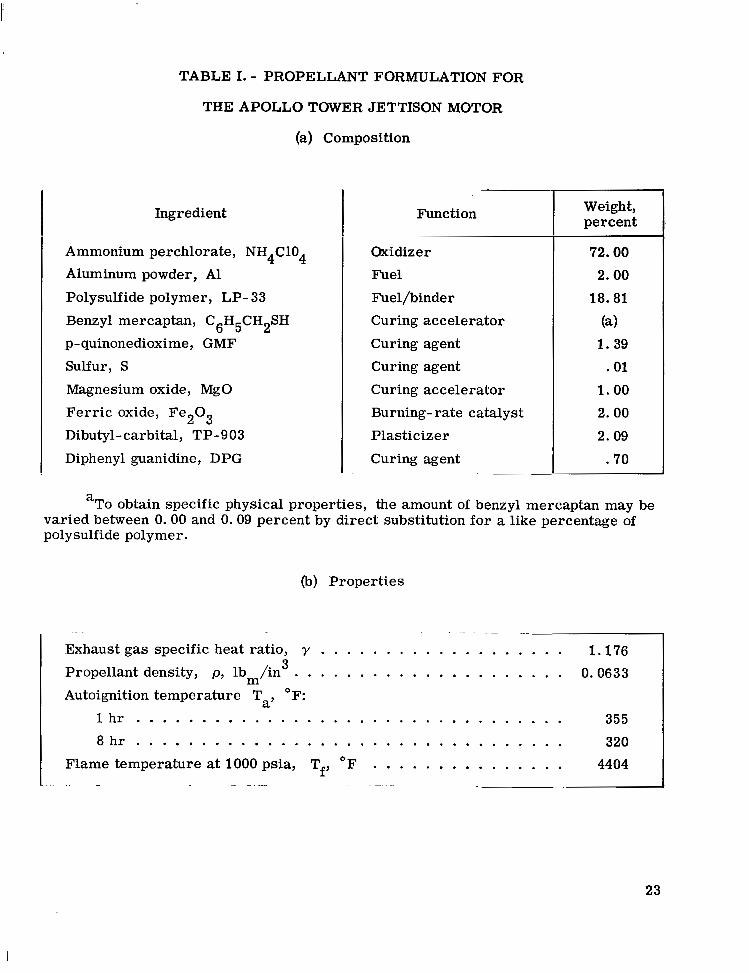
PROPELLANT FORMULATION FOR THE APOLLO TOWER JETTISON MOTOR
(a) Composition . . . . . . . . . . . . . . . . . . . . . . . . . . . . . 23 (b) Propert ies . . . . . . . . . . . . . . . . . . . . . . . . . . . . . . 23
SUMMARY OF ENVIRONMENTAL TESTING . . . . . . . . . . . . . . 24
SUMMARY OF MOTOR PERFORMANCE DATA . . . . . . . . . . . . 25
STATIC TEST INSTRUMENTATION . . . . . . . . . . . . . . . . . . 29
VARIATION OF MOTOR PERFORMANCE AS A FUNCTION OF MOTOR OPERATING TIME TRANSFORMED TO A PREFIRE-CONDITIONING TEMPERATURE OF 29" F AND THE TWO-SIDED TOLERANCE LIMITS
(a) Chamber pressure . . . . . . . . . . . . . . . . . . . . . . . . . 30 (b) Thrust corrected to sea-level pressure altitude (PA) . . . . . . . 35
VARIATION OF MOTOR PERFORMANCE AS A FUNCTION OF MOTOR OPERATING TIME TRANSFORMED TO A PREFIRE-CONDITIONING TEMPERATURE OF 70" F AND THE TWO-SIDED TOLERANCE LIMITS
(a) Chamber pressure . . . . . . . . . . . . . . . . . . . . . . . . . 40 (b) Thrust corrected to sea-level pressure altitude (PA) . . . . . . . 45
VARIATION OF MOTOR PERFORMANCE AS A FUNCTION OF MOTOR OPERATING TIME TRANSFORMED TO A PREFIRE-CONDITIONING TEMPERATURE OF 140" F AND THE TWO-SIDED TOLERANCE LIMITS
(a) Chamber pressure . . . . . . . . . . . . . . . . . . . . . . . . . 50 (b) Thrust corrected to sea-level pressure altitude (PA) . . . . . . . 55
SUMMARY OF MOTOR PERFORMANCE DATA TRANSFORMED TO SPECIFIC PREFIRE-CONDITIONING TEMPERATURES AND THE ONE-SIDED AND TWO-SIDED TOLERANCE LIMITS
(a) Transformed to 20" F . . . . . . . . . . . . . . . . . . . . . . . . 60 (b) Transformed to 70" F . . . . . . . . . . . . . . . . . . . . . . . . . 62 (c) Transformed to 140" F . . . . . . . . . . . . . . . . . . . . . . . 64
iv
". ~ ~ ............. 1

TABLES
Table Page
M SUMMARY OF MOTOR PHYSICAL MEASUREMENTS
(a) Motors tested in 1964 . . . . . . . . . . . . . . . . . . . . . . . . . 66 (b) Motors tested in 1965 . . . . . . . . . . . . . . . . . . . . . . . . . 67
X SUMMARY OF MOTOR PHYSICAL MEASUREMENTS AND THE ONE-SIDED AND TWO-SIDED TOLERANCE LIMITS . . . . . . 68
V
I
FIGURES
Figure
1 Saturn V launch vehicle and Apollo spacecraft . . . . . . . . . . . . . 2 Apollo launch escape system and command module . . . . . . . . . . 3 The tower jettison motor for the Apollo launch escape system
(a) Schematic . . . . . . . . . . . . . . . . . . . . . . . . . . . . . . . (b) Pictorial view . . . . . . . . . . . . . . . . . . . . . . . . . . . . (c) Photograph . . . . . . . . . . . . . . . . . . . . . . . . . . . . .
4 Nozzle assembly
(a) Schematic of small-throat nozzle . . . . . . . . . . . . . . . . . (b) Schematic of large-throat nozzle . . . . . . . . . . . . . . . . . . (c) Pictorial view . . . . . . . . . . . . . . . . . . . . . . . . . . . . (d) Photograph . . . . . . . . . . . . . . . . . . . . . . . . . . . . .
5 Propellant grain
(a) Schematic . . . . . . . . . . . . . . . . . . . . . . . . . . . . . . . (b) Photograph . . . . . . . . . . . . . . . . . . . . . . . . . . . . .
6 Motor ignition system
(a) Schematic of the TE-381 igniter assembly . . . . . . . . . . . . . (b) Pictorial view of the TE-381 igniter assembly . . . . . . . . . . (d) Pictorial view of Apollo standard initiator . Load of main (c) Schematic of pyrotechnic igniter cartridge . . . . . . . . . . . .
charge and ignition charge vary with lot . . . . . . . . . . . . . . (e) Schematic of igniter pellet container . . . . . . . . . . . . . . . . (f) Pictorial view of igniter pellet container . . . . . . . . . . . . .
Page
69
70
71 71 72
73 73 73 74
75 76
77 77 78
78 79 79
7 Impact testing
(a) Edgewise drop testing . . . . . . . . . . . . . . . . . . . . . . . 80 (b) Pendulum impact testing . . . . . . . . . . . . . . . . . . . . . . 81
8 Accelerometer and thermocouple locations and definition of axes
(a) Schematic of accelerometer locations (accelerometers 2 to 6 mounted on motor case) . . . . . . . . . . . . . . . . . . . . . 82
(b) Schematic of thermocouple locations . . . . . . . . . . . . . . . 82
vi
I

Figure Page
9 Vibration test fixtures
(a) Schematic of longitudinal vibration test fixture . . . . . . . . . . . 83
(c) Schematic of tr'msverse vibration test fixture . . . . . . . . . . . 84 (d) Photograph of longitudinal vibration test fixture
with temperature-conditioning unit . . . . . . . . . . . . . . . . 85
(b) Schematic of lateral vibration test fixture . . . . . . . . . . . . . 83
(e) Cornerwise drop testing . . . . . . . . . . . . . . . . . . . . . . . 86
10 Static test stand
(a) Schematic of top view . . . . . . . . . . . . . . . . . . . . . . . . 87 (b) Schematic of side view . . . . . . . . . . . . . . . . . . . . . . . . $7 (c) Schematic of end view . . . . . . . . . . . . . . . . . . . . . . . . 87
(e) Photograph. side view . . . . . . . . . . . . . . . . . . . . . . . . 89 (d) Photograph. end view . . . . . . . . . . . . . . . . . . . . . . . . 88
11 Variation of motor time characteristics as a function of prefire-conditioning temperature
(a) Ignition-delay times independent of prefire cavity
(b) Ignition-delay times of the two motors in ignition
(c) Ignition-delay times of the seven motors in ignition
(d) Ignition-delay times of the three motors in ignition
pressure and the number of igniter cartridges used . . . . . . . 90
category 1 (duplicated only a failed igniter cartridge) . . . . . . 90
category 2 (simulated only a failed nozzle closure) . . . . . . . 90
category 3 (duplicated a failed igniter cartridge and simulated a failed nozzle closure) . . . . . . . . . . . . . . 90
(e) Ignition-delay times of the five motors in ignition
(f) Thrust-rise times independent of prefire cavity
(g) Thrust-rise times of the two motors in ignition
(h) Thrust-rise times of the seven motors in ignition
(i) Thrust-rise times of the three motors in ignition
category 4 (duplicated normal ignition conditions) . . . . . . . . 91
pressure and the number of igniter cartridges used . . . . . . . 9 1
category 1 (duplicated only a failed igniter cartridge) . . . . . . 91
category 2 (simulated only a failed nozzle closure) . . . . . . . 9 1
category 3 (duplicated a failed igniter cartridge and simulated a failed nozzle closure) . . . . . . . . . . . . . . 92
(j) Thrust-rise times of the five motors in ignition category 4 (duplicated normal ignition conditions) . . . . . . . . 92
(k) Web burn time . . . . . . . . . . . . . . . . . . . . . . . . . . . . 92 (1) Action time . . . . . . . . . . . . . . . . . . . . . . . . . . . . . . 92 (m) Tailoff time . . . . . . . . . . . . . . . . . . . . . . . . . . . . . 93 (n )To ta l t ime . . . . . . . . . . . . . . . . . . . . . . . . . . . . . . 93
vii
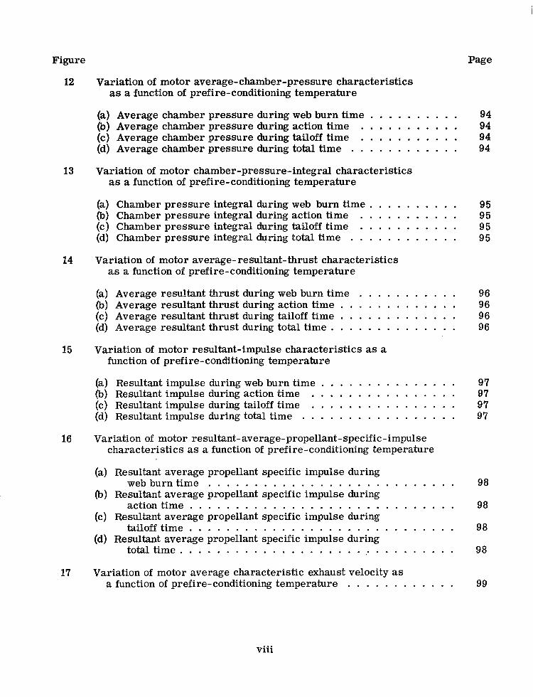
Figure Page
12 Variation of motor average-chamber-pressure characteristics as a function of prefire-conditioning temperature
(a) Average chamber pressure during web burn time . . . . . . . . . . 94 (b) Average chamber pressure during action time . . . . . . . . . . . 94 (c) Average chamber pressure during tailoff time . . . . . . . . . . . 94 (d) Average chamber pressure during total time . . . . . . . . . . . . 94
13 Variation of motor chamber-pressure-integral characteristics as a function of prefire-conditioning temperature
(a) Chamber pressure integral during web burn time . . . . . . . . . . 95
(c) Chamber pressure integral during tailoff time . . . . . . . . . . . 95 (b) Chamber pressure integral during action time . . . . . . . . . . . 95
(d) Chamber pressure integral during total time . . . . . . . . . . . . 95
14 Variation of motor average-resultant-thrust characteristics as a function of prefire-conditioning temperature
(a) Average resultant thrust during web burn time . . . . . . . . . . . 96 (b) Average resultant thrust during action time . . . . . . . . . . . . . 96 (c) Average resultant thrust during tailoff time . . . . . . . . . . . . . 96 (d) Average resultant thrust during total time . . . . . . . . . . . . . . 96
15 Variation of motor resultant-impulse characteristics as a function of prefire-conditioning temperature
(a) Resultant impulse during web burn time . . . . . . . . . . . . . . . 97 (b) Resultant impulse during action time . . . . . . . . . . . . . . . . 07 (c) Resultant impulse during tailoff time . . . . . . . . . . . . . . . . 97 (d) Resultant impulse during total time . . . . . . . . . . . . . . . . . 97
16 Variation of motor resultant-average-propellant-specific-impulse characteristics as a function of prefire-conditioning temperature
(a) Resultant average propellant specific impulse during
(b) Resultant average propellant specific impulse during
(c) Resultant average propellant specific impulse during
(d) Resultant average propellant specific impulse during
web burn time . . . . . . . . . . . . . . . . . . . . . . . . . . . 98
action time . . . . . . . . . . . . . . . . . . . . . . . . . . . . . 98
tailoff time . . . . . . . . . . . . . . . . . . . . . . . . . . . . . 98
total time . . . . . . . . . . . . . . . . . . . . . . . . . . . . . . 98
17 Variation of motor average characteristic exhaust velocity as a function of prefire-conditioning temperature . . . . . . . . . . . . 99
viii

Figure Page
18 Variation of motor average burning rate during web burn time as a function of prefire-conditioning temperature . . . . . . . . . . 99
19 Variation of motor maximum chamber pressure as a function of prefire-conditioning temperature . . . . . . . . . . . . 99
20 Variation of motor average resultant thrust-vector excursion angle as a function of motor average location of resultant thrust vector . . . . . . . . . . . . . . . . . . . . . . . . . . . . . 99
21 Nominal motor performance as a function of operating time and the calculated statistical limits (two-sided tolerance limits) at 20" F
(a) Chamber pressure . . . . . . . . . . . . . . . . . . . . . . . . . 100 (b) Resultant thrust . . . . . . . . . . . . . . . . . . . . . . . . . . . 100
22 Nominal motor performance as a function of operating time and the calculated statistical limits (two-sided tolerance limits) at 70" F
(a) Chamber pressure . . . . . . . . . . . . . . . . . . . . . . . . . 101 (b) Resultant thrust . . . . . . . . . . . . . . . . . . . . . . . . . . . f O f
23 Nominal motor performance as a function of operating time and the calculated statistical limits (two-sided tolerance limits) at 140" F
(a) Chamber pressure . . . . . . . . . . . . . . . . . . . . . . . . . 102 (b) Resultant thrust . . . . . . . . . . . . . . . . . . . . . . . . . . . 102
24 Time characteristics definition
(a) Based on chamber pressure . . . . . . . . . . . . . . . . . . . . 103 (b) Based on thrust . . . . . . . . . . . . . . . . . . . . . . . . . . . 103
ix
QUALIFICATION EVALUATION OF THE TOWER JETTISON
MOTOR FOR THE APOLLO SPACECRAR- PROGRAM
LAUNCH ESCAPE SYSTEM
By B. J. Lee Manned Spacecraft Center
SUMMARY
The Apollo spacecraft launch escape system provides the capability for a suc- cessful mission abort if any system affecting crew safety should malfunction. The launch escape system is designed to provide this capability from the earliest practicable time following crew insertion into the command module until the launch escape system is jettisoned from, and out of the path of, the command module shortly after the launch vehicle second-stage ignition and staging. If any system affecting crew safety should malfunction, the launch escape system will separate the command module from, and out of the path of, the launch vehicle. Propulsion for the launch escape system is provided by the launch escape, pitch control, and tower jettison motors.
To evaluate the performance of each motor, programs were established for de- velopment, qualification, and flight tests. A summary is presented of the qualification test program, which includes environmental testing and static test firing, of the tower jettison motor. In addition, the static-test-firing.data are evaluated statistically with regard to the specifications.
The environmental testing phase of the qualification test program was conducted by using 15 tower jettison motors that were divided into the following environmental test groups:
1. Group A - tempefature cycling
2. Group B - accelerated aging
3. Group C - temperature cycling and impact testing
4. Group D - vibration testing, temperature cycling, and impact testing
The static-test-firing phase of the qualification test program was conducted by using 21 tower jettison motors of which 15 were tested environmentally and six were not tested environmentally. These 2 1 motors were assigned to three prefire- conditioning temperature groups: 20" F (nine motors), 70" F (five motors), and 140" F (seven motors). The motors were static test fired at a nominal pressure altitude of 14.7 psia.
I'

The Apollo tower jettison motor specifications require that certain performance parameters meet specific tolerance limits at prefire-conditioning temperatures of 20°, 70°, and 140" F.
Because a solid-propellant rocket motor of fixed geometry and given propellant will yield a different performance at differing prefire-conditioning temperatures, and since there were only a limited number of motors allotted to the qualificoation test pro- gram, all motor performance data were transformed to the specified 20 , 70°, and 140" F prefire-conditioning temperatures to increase the statistical confidence; a sta- tistical analysis was then performed on these transformed data. From an analysis of the results of the qualification tests, it was confirmed that the tower jettison motor meets the specifications of the Apollo Spacecraft Program.
INTRODUCTION
The Apollo spacecraft launch escape system (LES) (figs. 1 and 2) provides the capability for a successful mission abort if any system affecting crew safety should malfunction. The LES is designed to provide this capability from the earliest practi- cable time following crew insertion into the command module until the LES is jettisoned from, and out of the path of, the command module (CM) shortly after the launch vehicle second-stage ignition and staging. If any system affecting crew safety should malfunc- tion, the LES will separate the CM from, and out of the path of, the launch vehicle (LV).
The LES (fig. 2) consists of the following:
1. The Q-ball assembly (located at the forward extremity of the LES) provides the aerodynamic incidence-angle and dynamic-pressure measurements that are re- quired by the LV and the launch escape emergency detection system.
2. The canard assembly (an aerodynamic control mechanism) reorients the separated CM/LES in a heat-shield-forward attitude to allow satisfactory deployment of the earth recovery system after the LES is jettisoned from the CM and removed from the CM path.
3. The ballast provides aerodynamic stability for the CM/LES after separation from the LV.
4. The launch escape motor (a 3.23-KS-139400 solid-propellant rocket motor) provides the LES propulsion to separate the CM fro?, and out of the path of, the LV. A nominal thrust-vector angle of approximately 2.75 from the motor longitudinal axis is required for the removal of the CM/LES from the path of the LV. To provide the correct thrust-vector angle, the throat area of one of the two nozzles in the pitch plane is approximately 15 percent larger than the throat area of either of the two yaw-plane nozzles that are approximately equal in size. The throat area of the second nozzle in the pitch plane is approximately 13 percent smaller than the throat area of either of the two nozzles in the yaw plane. During a nominal flight, the launch escape motor can be used to jettison the LES if the tower jettison motor malfunctions.
2
5. The pitch control motor .(a 0.62-KS-2170 solid-propellant rocket motorb which is ignited in conjunction with the launch escape motor, is used to provide a 15 to 20" down-range pitchover of the CM/LES immediately after initiation of a mission abort either from the launch pad o r until 41 seconds after lift-off, at which time an alti- tude of approximately 10 000 feet is reached.
6. The tower jettison motor (a 1.2-KS-33800 solid-propellant rocket motor) pro- vides the primary propulsion to jettison the LES from the CM after the LV second-stage ignition and staging. A nominal thrust-vector angle of approximately 4" from the motor longitudinal axis is required for the removal of the jettisoned LES from the CM path. To provide the correct thrust-vector angle, the throat area of one of the two tower- jettison-motor nozzles is approximately 16 percent larger than the throat area of-the other nozzle. During a mission abort, the tower jettison motor is used to separate the LES from the CM (after burnout of the launch escape and pitch control motors) and to remove the LES from the CM path.
7. A tower structure forms the intermediate construction between the CM and the launch escape motor.
8. A boost protective cover shields the CM thermal coating, windows, and for- ward heat shield from the dynamic-pressure and aerodynamic-heating environment imposed during booster operations and from the launch-escape-motor and tower- jettison-motor exhaust products.
To evaluate the performance of the launch escape, pitch control, and tower jetti- son motors, programs were established for development, qualification, and flight tests. A summary of the tower-jettison-motor qualification test program, which included en- vironmental testing and static test firing, is presented. In addition, the static-test-, firing data a r e evaluated statistically with regard to the specifications.
SYMBOLS
At throat area, in 2
C* characteristic exhaust velocity, ft/sec
C* average characteristic exhaust velocity, ft/sec
F resultant thrust, lbf
Fa
-
- average resultant thrust during action time, lbf
- Fb average resultant thrust during web burn time, lbf
F maximum resultant thrust, lbf max.
3
I
- Ft average resultant thrust during total time, lbf
- Ftail average resultant thrust during tailoff time, lb
f
g y H z acceleration density
gravitational conversion factor, 32.174 lbm-ft lbf-sec / 2 gC
I - resultant impulse, lbf-sec
'a resultant impulse during action time, lbf-sec
Ib resultant impulse during web burn time, lbf-sec
I resultant propellant specific impulse, lbf-sec lbm SP /
It resultant impulse during total time, lbf-sec
Itail
f resultant average propellant specific impulse during action time, lbf-sec lbm
resultant impulse during tailoff time, lbf-sec
SP, a / f SP, b
-
Isp, tail
P
P max.
resultant average propellant specific impulse during web burn time, lbf - sec/lbm
resultant average propellant specific impulse during total time, lbf-sec / lbm
resultant average propellant specific impulse during tailoff time, lbf-sec lbm / chamber pressure, psia
maximum chamber pressure, psia
average chamber pressure during action time, psia
average chamber pressure during web burn time, psia
- Pt average chamber pressure during total time, psia
pt,il average chamber pressure during tailoff time, psia
4
r
r - b
T
Ta
Tf
T P
t
ta
5 3
td
tf
tf
tt
‘tail
max .
W P
Y
e
P
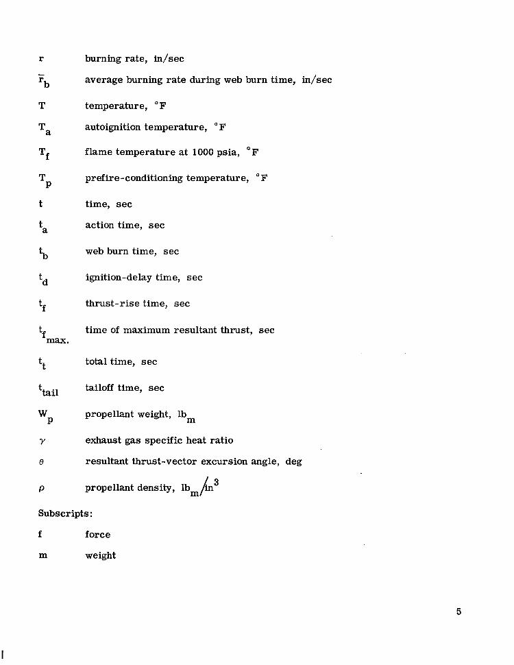
burning rate, in/sec
average burning rate during web burn time, in/sec
temperature, OF
autoignition temperature, OF
flame temperature at 1000 psia, F
prefire-conditioning temperature, OF
time, sec
action time, sec
web burn time, sec
ignition-delay time, sec
thrust-rise time, sec
time of maximum resultant thrust, sec
total time, sec
tailoff time, sec
propellant weight, lbm
exhaust gas specific heat ratio
resultant thrust-vector excursion angle, deg
propellant density, lbm/h3
Subscripts:
f force
m weight
5
I
111 I l l I II II II . m 1.1.1
TOWER JETTl SON MOTOR DESCRI PTI ON
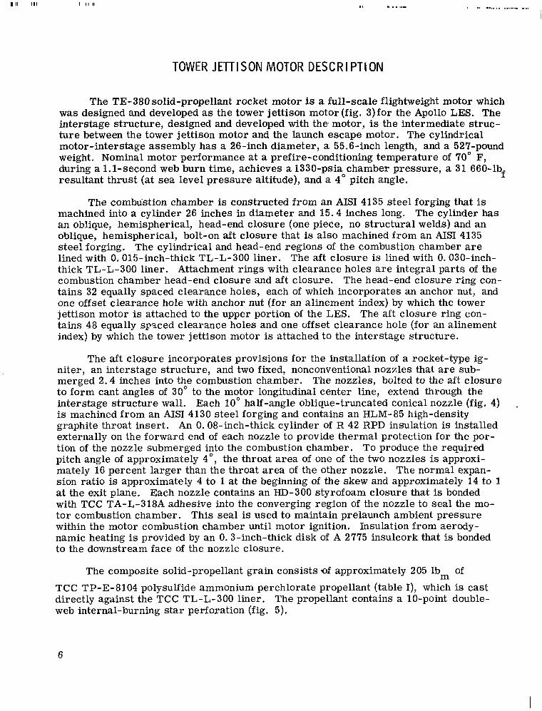
The TE-380 solid-propellant rocket motor is a full-scale flightweight motor which was designed and developed as the tower jettison motor (fig. 3)for the Apollo LES. The interstage structure, designed and developed with t h e motor, is the intermediate struc- ture between the tower jettison motor and the launch escape motor. The cylindrical motor-interstage assembly has a 26-inch diameter, a 55.6-inch length, and a 527-pound weight. Nominal motor performance at a prefire-conditioning temperature of 70" F, during a 1.1-second web burn time, achieves a 1330-psia chamber pressure, a 31 660-lbf resultant thrust (at sea level pressure altitude), and a 4" pitch angle.
The combtistion chamber is constructed from an AISI 4135 steel forging that is machined into a cylinder 26 inches in diameter and 15.4 inches long. The cylinder has an oblique, hemispherical, head-end closure (one piece, no structural welds) and an oblique, hemispherical, bolt-on aft closure that is also machined from an AISI 4135 steel forging. The cylindrical and head-end regions of the combustion chamber are lined with 0.015-inch-thick TL-L-300 liner. The aft closure is lined with 0.030-inch- thick TL-L-300 liner. Attachment rings with clearance holes are integral parts of the Combustion chamber head-end closure and aft closure. The head-end closure ring con- tains 32 equally spaced clearance holes, each of which incorporates an anchor nut, and one offset clearance hole with anchor nut (for an alinement index) by which the tower jettison motor is attached to the upper portion of the LES. The aft closure ring con- tains 48 equally spaced clearance holes and one offset clearance hole (for an alinement index) by which the tower jettison motor is attached to the interstage structure.
The aft closure incorporates provisions for the installation of a rocket-type ig- niter, an interstage structure, and two fixed, nonconventional nozzles that are sub- merged 2.4 inches into the combustion chamber. The nozzles, bolted to the aft closure to form cant angles of 30" to the motor longitudinal center line, extend through the interstage structure wall. Each 10" half-angle oblique-truncated conical nozzle (fig. 4) . is machined from an AISI 4130 steel forging and contains an HLM-85 high-density graphite throat insert. An 0.08-inch-thick cylinder of R 42 RPD insulation is installed externally on the forward end of each nozzle to provide thermal protection for the por- tion of the nozzle submerged into the combustion chamber. To produce the required pitch angle of approximately 4", the throat area of one of the two nozzles is approxi- mately 16 percent larger than the throat area of the other nozzle. The normal expan- sion ratio is approximately 4 to 1 at the beginning of the skew and approximately 14 to 1 at the exit plane. Each nozzle contains an HD-300 Styrofoam closure that is bonded with TCC TA-L-318A adhesive into the converging region of the nozzle to seal the mo- tor combustion chamber. This seal is used to maintain prelaunch ambient pressure within the motor combustion chamber until motor ignition. Insulation from aerody- namic heating is provided by an 0.3-inch-thick disk of A 2775 insulcork that I s bonded to the downstream face of the nozzle closure.
The composite solid-propellant grain consists of approximately 205 lbm of TCC TP-E-8104 polysulfide ammonium perchlorate propellant (table I), which is cast directly against the TCC TL-L-300 liner. The propellant contains a 10-point double- web internal-burning star perforation (fig. 5).
6
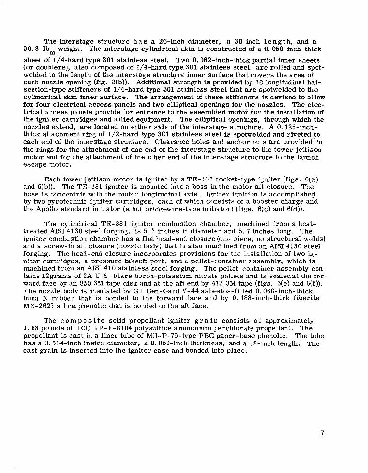
The interstage structure h a s a 26-inch diameter, a 30-inch 1 e n g t h, and a 90. 3-lbm weight. The interstage cylindrical skin is constructed of a 0.050-inch-thick sheet of 1/4-hard type 301 stainless steel. Two 0.062-inch-thick partial inner sheets (or doublers), also composed of 1/4-hard type 301 stainless steel, are rolled and spot- welded to the length of the interstage structure inner surface, that covers the area of each nozzle opening (fig. 3(b)). Additional strength is provided by 18 longitudinal hat- section-type stiffeners of 1/4-hard type 301 stainless steel that are spotwelded to. the cylindrical skin inner surface. The arrangement of these stiffeners is devised to allow for four electrical access panels and two elliptical openings for the nozzles. The elec- trical access panels provide for entrance to the assembled motor for the installation of the igniter cartridges and allied equipment. The elliptical openings, through which the nozzles extend, are located on either side of the 5nterstage structure. A 0.125-inch- thick attachment ring of 1/2-hard type 301 stainless steel is spotwelded and riveted to each end of the interstage structure. Clearance holes and anchor nuts %re provided' in the rings for the attachment of one end of the. interstage structure to the tower jettison motor and for the attachment of the other end of the interstage structure to the launch escape motor.
Each tower jettison motor is ignited by a TE-381 rocket-type igniter (figs. 6(a) and 6(b)). The TE-381 igniter is mounted into a boss in the motor aft closure. The boss is concentric with the motor longitudinal axis. Igniter ignition is accomplished by two pyrotechnic igniter cartridges, each of which consists of a booster charge and the Apollo standard initiator (a hot bridgewire-type initiator) (figs. 6(c) and 6(d)).
The cylindrical TE- 38 1 igniter combustion chamber, machined from a heat- treated AISI 4130 steel forging, is 5.3 inches in diameter and 5.7 inches long. The igniter combustion chamber has a flat head-end closure (one piece, no structural welds) and a screw-in aft closure (nozzle body) that is also machined from an AISI 4130 steel forging. The head-end closure incorporates provisions for the installation of two ig- niter cartridges, a pressure takeoff port, and a pellet-container assembly, which is machined from an AISI 410 stainless steel forging. The pellet-container assembly con- tains 12 grams of 2A U. s. Flare boron-potassium nitrate pellets and is sealedat the for- ward face by an 850 3M tape disk and at the aft end by 473 3M tape (figs. 6(e) and 6(f)). The nozzle body is insulated by GT Gen-Gard V-44 asbestos-filled 0.060-inch-thick buna N rubber that is bonded to the forward face and by 0.188-inch-thick fiberite MX-2625 silica phenolic that is bonded to the aft face.
The c o m p o s i t e solid-propellant igniter g r a in consists o f approximately 1.83 pounds of TCC TP-E-8104 polysulfide ammonium perchlorate propellant. The propellant is cast in a liner tube of Mil-P-79 -type PBG paper-base phenolic. The tube has a 3. 534-inch inside diameter, a 0.050-inch thickness, and a 12-inch length. The cast grain is inserted into the igniter case and bonded into place.

ENVIRONMENTAL TESTING
The environmental testing phase of the qualification test program (table 11, refs. 1 and 2) was conducted by using 15 tower jettison motors that were assigned to the following environmental test groups:
1. Group A - temperature cycling
2. Group B - accelerated aging
3. Group C - temperature cycling and impact testing
4. Group D - vibration testing, temperature cycling, and impact testing
The procedures for each test group were conducted in the following manner.
Temperature Cycling
Tower jettison motors serial number (SN) AQ-VII- 1, SN A&-VIII- 1, SN A&-IX- 1, SN AQ-"2, SN AQ-"3, SN AQ-IX-4, and SN AQ-XI-1 were assigned to test group A, temperature cycling. Motors SN AQ-VIII-1, SN A&-E-1, SN AQ-X-2, SN AQ-IX-3 and SN AQ-IX-4 were temperature cycled by successive stabilization at 140", -20°, 140", -20°, and 140" F. Motors SN AQ-VII-1 and SN AQ-XI-1 were temperature cy- cled by successive stabilization at -20"; 140", -20", 140", and -20" F. After being temperature cycled, all motors were inspected visually and found to be free of. defect.
Accelerated Aging
Tower jettison motors SN AQ-X-1 and SN AQ-X-2, assigned to test groupB, were aged for 75 days at 160" F. Both motors were then static test fired.
Temperature Cycling and I mpact Testing
Tower jettison motors SN AQ-V-1 and SN AQ-V-2 were assigned to test group C for temperature cycling and impact testing. Motor SN AQ-V-1 was placed in a ship- ping container, and with the shipping container lid removed, the motor was tempera- ture cycled by successive stabilization at 140", -Zoo, 140°, -20", and 140" F. The motor was stabilized at 70" F, and the lid was reinstalled on the shipping container. The container was removed from the temperature-conditioning unit, delivered to the drop-test facility, and positioned with one end of the container base on a sill 5 inches high. The opposite end of the container base was raised to 18 inches and allowed to free fall onto solid, reinforced concrete (fig. 7(a)). This edgewise drop test was applied once to each end of the container. During the edgewise drop-test preparations, the motor and the shipping container w e r e exposed t o ambient temperature for 16 minutes.
8
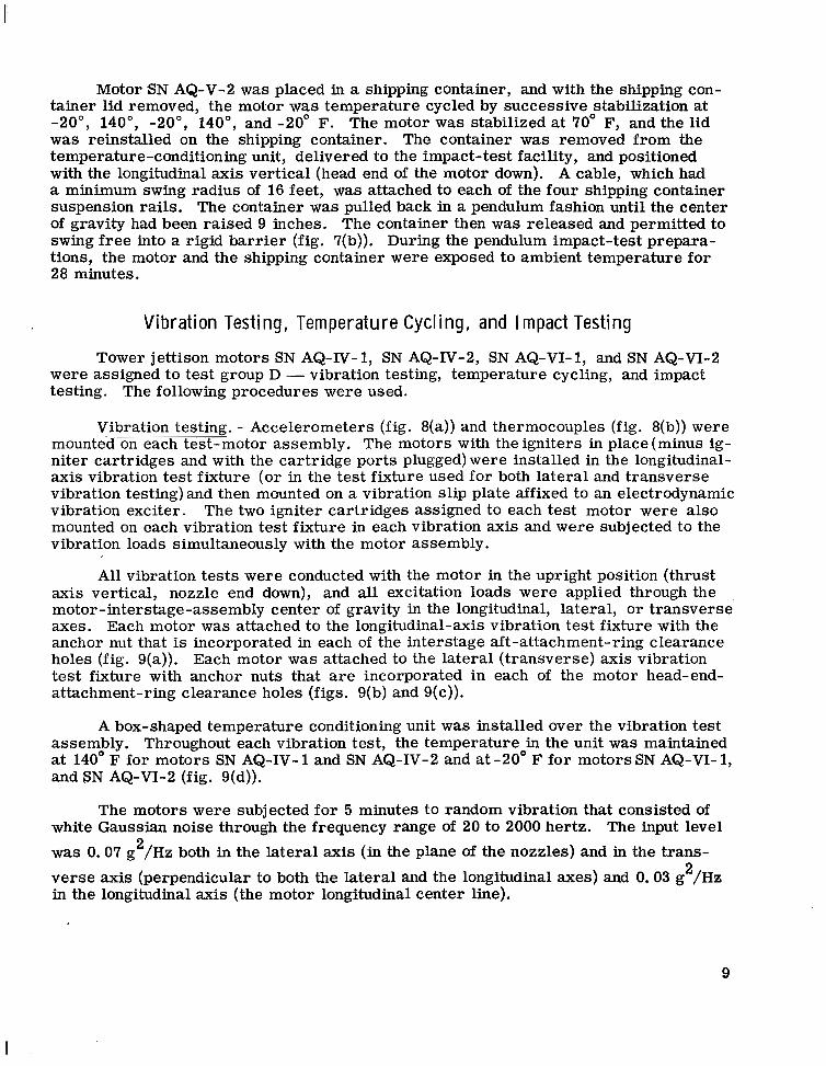
Motor -SN AQ-V-2 was placed in a shipping container, and with the shipping con- tainer lid removed, the motor was temperature cycled by successive stabilization at -20°, 140°, -20°, 140°, and -20" F. The motor was stabilized at 70" F, and the lid was reinstalled on the shipping container. The container was removed from the temperature-conditioning unit, delivered to the impact-test facility, and positioned with the longitudinal axis vertical (head end of the motor down). A cable, which had a minimum swing radius of 16 feet, was attached to each of the four shipping container suspension rails. The container was pulled back in a pendulum fashion until the center of gravity had been raised 9 inches. The container then was released and permitted to swing free into a rigid barrier (fig. 7(b)). During the pendulum impact-test prepara- tions, the motor and the shipping container were exposed to ambient temperature for 28 minutes.
Vibration Testing, Temperature Cycling, and Impact Testing
Tower jettison motors SN AQ-IV-1, SN AQ-IV-2, SN AQ-VI-1, and SN AQ-VI-2 were assigned to test group D - vibration testing, temperature cycling, and impact testing. The following procedures were used.
Vibration testing. - Accelerometers (fig. 8(a)) and thermocouples (fig. 8(b)) were mounted on each test-motor assembly. The motors with theigniters in place(minus ig- niter cartridges and with the cartridge ports plugged) were installed in the longitudinal- axis vibration test fixture (or in the test fixture used for both lateral and transverse vibration testing)and then mounted on a vibration slip plate affixed to an electrodynamic vibration exciter. The two igniter cartridges assigned to each test motor were also mounted on each vibration test fixture in each vibration axis and were subjected to the vibration loads simultaneously with the motor assembly.
All vibration tests were conducted with the motor in the upright position (thrust axis vertical, nozzle end down), and all excitation loads were applied through the motor-interstage-assembly center of gravity in the longitudinal, lateral, or transverse axes. Each motor was attached to the longitudinal-axis vibration test fixture with the anchor nut that is incorporated in each of the interstage aft-attachment-ring clearance holes (fig. 9(a)). Each motor was attached to the lateral (transverse) axis vibration test fixture with anchor nuts that are incorporated in each of the motor head-end- attachment-ring clearance holes (figs. 9(b) and 9(c)).
A box-shaped temperature conditioning unit was installed over the vibration test assembly. Throughout each vibration test, the temperature in the unit was maintained at 140' F for motors SN AQ-IV- 1 and SN AQ-IV-2 and at -20' F for motors SN AQ-VI- 1, and SN AQ-VI-2 (fig. 9(d)).
The motors were subjected for 5 minutes to random vibration that consisted of white Gaussian noise through the frequency range of 20 to 2000 hertz. The input level was 0.07 g /Hz both in the lateral axis (in the plane of the nozzles) and in the trans- verse axis (perpendicular to both the lateral and the longitudinal axes) and 0.03 g /Hz in the longitudinal axis (the motor longitudinal center line).
2 2
9
I
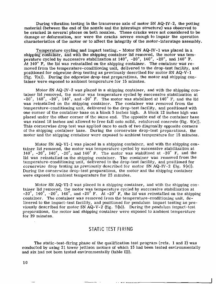
During vibration testing in the transverse axis of motor SN AQ-IV-2, the potting material (between the end of the nozzle and the interstage structure) was observed to be cracked in several places on both nozzles. These cracks were not considered to be damage or deformation, nor were the cracks severe enough to impair the operation characteristics of the motor or to affect the integrity of the motor-interstage assembly.
Temperature cycling ~~ " and .. . impact testing. - Motor SN AQ-N-1 was placed in a shipping container, and with the shipping container lid removed, the motor was tem- perature cycled by successive stabilization at 140", -20", 140", -20", and 140" F. At 140" F, the lid was reinstalled on the shipping container. The container was re- moved from the temperature-conditioning unit, delivered to the drop-test facility, and positioned for edgewise drop testing as previously described for motor SN AQ-V-1 (fig. 7(a)). During the edgewise drop-test preparations, the motor and shipping con- tainer were exposed to ambient temperature for 15 minutes.
Motor SN AQ-N-2 was placed in a shipping container, and with the shipping con- tainer lid removed, the motor was temperature cycled by successive stabilization at -20", 140°, -20", 140", and -20" F. The motor was stabilized at 140" F, and the lid was reinstalled on the shipping container. The container was removed from the temperature-conditioning unit, delivered to the drop-test facility, and positioned with one corner of the container base on a block 5 inches high. A block 12 inches high was placed under the other corner of the same end. The opposite end of the container base was raised 18 inches and allowed to f ree fall onto solid, reinforced concrete (fig. 9(e)). This cornerwise drop test was applied once to each of two diagonally opposite corners of the shipping container base. During the cornerwise drop-test preparations, the motor and the shipping container were exposed to ambient temperature for 15 minutes.
Motor SN AQ-VI-1 was placed in a shipping container, and with the shipping con- tainer lid removed, the motor was temperature cycled by successive stabilization at 140", -20°, 140", -20°, and 140" F. The motor was stabilized at -20" F, and the lid was reinstalled on the shipping container. The container was removed from the temperature-conditioning unit, delivered to the drop-test facility, and positioned for cornerwise drop testing as previously described for motor SN AQ-IV-2 (fig. 9(e)). During the cornerwise drop-test preparations, the motor and the shipping container were exposed to ambient temperature for 25 minutes.
Motor SN AQ-VI-2 was placed in a shipping container, and with the shipping con- tainer lid removed, the motor was temperature cycled by successive stabilization at -20", 140", -20", 140", and -20" F. At -20" F, the lid was reinstalled on the shipping container. The container was removed from the temperature-conditioning unit, de- livered to the impact-test facility, and positioned for pendulum impact testing as pre- viously described for motor SN AQ-V-2 (fig. 7(b)). During the pendulum impact-test preparations, the motor and shipping container were exposed to ambient temperature for 29 minutes.
STAT1 C TEST FI RING
The static-test-firing phase of the qualification test program (refs. 1 and 2) was conducted by using 21 tower jettison motors of which 15 had been tested environmentally and six had not been tested environmentally (table III).
10
I nstallation
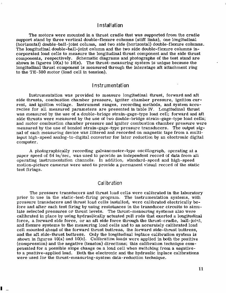
The motors were mounted in a thrust cradle that was supported from the cradle support stand by three vertical double-flexure columns (stiff links), one longitudinal (horizontal) double-ball-joint column, and two side (horizontal) double-flexure columns. The longitudinal double-ball-joint column and the two side double-flexure columns in- corporated load cells to measure the longitudinal thrust component and the side thrust components, respectively. Schematic diagrams and photographs of the test stand are shown in figures lO(a) to lO(e). The thrust-measuring system is unique because the longitudinal thrust component is measured through the interstage aft attachment ring to the TE-380 motor (load cell in tension).
Instrumentation
Instrumentation was provided to measure longitudinal thrust, forward and aft side thrusts, combustion chamber pressure, igniter chamber pressure, ignition cur- rent, and ignition voltage. Instrument ranges, recording methods, and system accu- racies for all measured parameters are presented in table IV. Longitudinal thrust was measured by the use of a double-briage strain-gage-type load cell; forward and aft side thrusts were measured by the use of two double-bridge strain-gage-type load cells; and motor combustion chamber pressure and igniter combustion chamber pressure were measured by the use of bonded strain-gage-type pressure transducers. The output sig- nal of each measuring device was filtered and recorded on magnetic tape from a multi- input high-speed analog-to-digital converter for later reduction by an electronic digital computer.
A photographically recording galvanometer-type oscillograph, operating at a paper speed of 64 in/sec, was used to provide an independent record of data from all operating instrumentation channels. In addition, standard- speed and high-speed motion-picture cameras were used to provide a permanent visual record of the static test firings.
Calibration
The pressure transducers and thrust load cells were calibrated in the laboratory prior to use in the static-test-firing program. The instrumentation systems, with pressure transducers and thrust load cells installed, were calibrated electrically be- fore and after each test firing by using resistances in the transducer circuits to simu- late selected pressures o r thrust levels. The thrust-measuring systems also were calibrated in place by using hydraulically actuated pull rods that exerted a longitudinal force, a forward side force, o r an aft side force through the thrust-cradle, ball-joict, and flexure systems to the measuring load cells and to an accurately calibrated load cell mounted ahead of the forward thrust buttress, the forward side-thrust buttress, and the aft side-thrust buttress. Only the longitudinal inplace calibration system is shown in figures lO(a) and 10(b). Calibration loads were applied in both the positive (compression) and the negative (tension) directions; this calibration technique com- pensated for a possible slope change on a load cell when switching from a negative- to a positive-applied load. Both the electronic and the hydraulic inplace calibrations were used for the thrust-measuring-system data-reduction technique.
11
I

Preselected Controlled Static-Test-Firing Conditions
The 21 motors to be static test fired were divided into three prefire-conditioning temperature groups: 20" F (nine motors), 70" F (five motors), and 140' F (seven motors). Each temperature group was subdivided into the following ignition categories.
1. Category 1 - Simulated only a failed igniter cartridge
2. Category 2 - Simulated only a failed nozzle closure
3. Category 3 - Simulated a failed igniter cartridge and simulated a failed nozzle closure
4. Category 4 - Simulated normal ignition conditions
The nine motors assigned to the 20" F temperature group were subdivided into ignition categories as follows: category 1, one motor; category 2, three motors; category 3, two motors; and category 4, three motors. Motor SN-AQ-111-2 in cate- gory 4 of this temperature group experienced a failure of its interstage structure dur- ing the ignition transient of the static test firing, with subsequent destruction of the motor assembly. Consequently, all static test performance data for this motor are deleted from the performance evaluation. The justification for deletion of these data is presented in the section entitled "Failure Analysis. ''
The five motors assigned to the 70" F temperature group were subdivided into ignition categories as follows: category 1, none; category 2, two motors; category 3, one motor; and category 4, two motors. Data are available from all motors in this group.
The seven motors assigned to the 140" F temperature group were subdivided into ignition categories as follows: category 1, one motor; category 2, four motors; cate- gory 3, one motor; and category 4, one motor. Motors SN AQ-V-1 and SN AQ-X-1 in category 2 and motor SN AQ-VIII-1 in category 3 of this temperature group displayed unusually long igniter ignition-delay times, which resulted in prolonged ignition-delay times, thrust-rise times, and total firing times for each motor. Consequently, these data were deleted from the performance evaluation. The justification for deletion of these data is presented in the section entitled "Failure Analysis. ' '
Motor Performance Data and Analysis
The static-test-firing motor performance data are summarized in table 111 and are presented in figures 11 to 23. The motors were static test fired at a nominal pressure altitude of 14.7 psia (sea level). Therefore, all motor performance data are values obtained at approximately sea-level pressure altitude (table 111). A technique to correct these performance test values to vacuum pressure altitude values is pre- sented in reference 3.
The specification (ref. 2) for the Apollo tower jettison motor requires that cer- tain performance parameters meet, specific tolerance limits at prefire-conditioning temperatures of 20", 70", and 140 F. Because a solid-propellant rocket motor of
1 2
fixed geometry and given propellant will yield a different performance at differing prefire-conditioning temperatures, the motor performance data were transformed to the specified 20", 70", and 140" F prefire-conditioning temperatures to increase the statistical confidence; a statistical analysis was then performed on these transformed data. The variation of motor performance as a function of motor operating time trans- formed to the specified 20°, 70°, and 140" F prefire-conditioning temperatures and the two-sided tolerance limits are presented in tables V to VU and in figures 21 to 23. The minimum and maximum two-sided tolerance limits in figures 21 to 23 are not ac- tual minimum and maximum performance traces, but are only the bounds within which these traces will lie.
The statistical analysis consisted of calculating means, standard deviations, one-sided tolerance limits, and two-sided tolerance limits (for 99 percent of the popu- lation with 95-percent confidence). As previously mentioned, the data for motors SN AQ-III-2, SN AQ-V-1, SN AQ-VIII-1, and SN AQ-X-1 have been deleted from the performance evaluation. The justification for deleting these data is presented in the section entitled "Failure Analysis. ''
The data analysis method used in this report is discussed in reference 3. When more than one instrumentation channel was used to obtain values for a single param- eter, the average of these values was used, unless otherwise noted, to calculate the data presented in the following discussion.
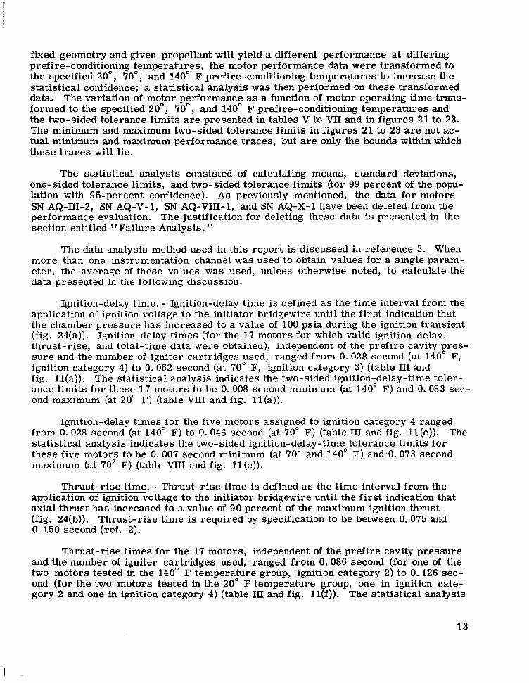
Ignition-delay time. - Ignition-delay time is defined as the time interval from the application of ignition voltage to the initiator bridgewire until the first indication that the chamber pressure has increased to a value of 100 psia during the ignition transient (fig. 24(a)). Ignition-delay times (for the 17 motors for which valid ignition-delay, thrust-rise, and total-time data were obtained), independent of the prefire cavity gres- sure and the number of igniter cartridges used, ranged from 0.028 second (at 140 F, ignition category 4) to 0.062 second (at 70" F, ignition category 3) (table 111 and fig. ll(a)). The statistical analysis indicates the two-sided ignition-delay-time toler- ance limits for these 17 motors to be 0. 008 second minimum (at 140" F) and 0.083 sec- ond maximum (at 20" F) (table W I and fig. 11 (a)).
Ignition-delay times for the five motors assigned to ignition category 4 ranged from 0.028 second (at 140" F) to 0.046 second (at 70" F) (table 111 and fig. l l (e)) . The statistical analysis indicates the two-sided ignition-delay-time tolerance limits for these five motors to be 0.007 second minimum (at 70" and 140" F) and 0.073 second maximum (at 70" F) (table VIlI and fig. l l (e)) .
Thrust-rise time. - Thrust-rise time is defined as the time interval from the application of ignition voltage to the initiator bridgewire until the first indication that axial thrust has increased to a value of 90 percent of the maximum ignition thrust (fig. 24(b)). Thrust-rise time is required by specification to be between 0.075 and 0.150 second (ref. 2).
Thrust-rise times for the 17 motors, independent of the prefire cavity pressure and the number of igniter cartridges used, ranged from 0.086 second (for one of the two motors tested in the 140" F temperature group, ignition category 2) to 0.126 sec- ond (for the two motors tested in the 20" F temperature group, one in ignition cate- gory 2 and one in ignition category 4) (table 111 and fig. ll(f)). The statistical analysis
13
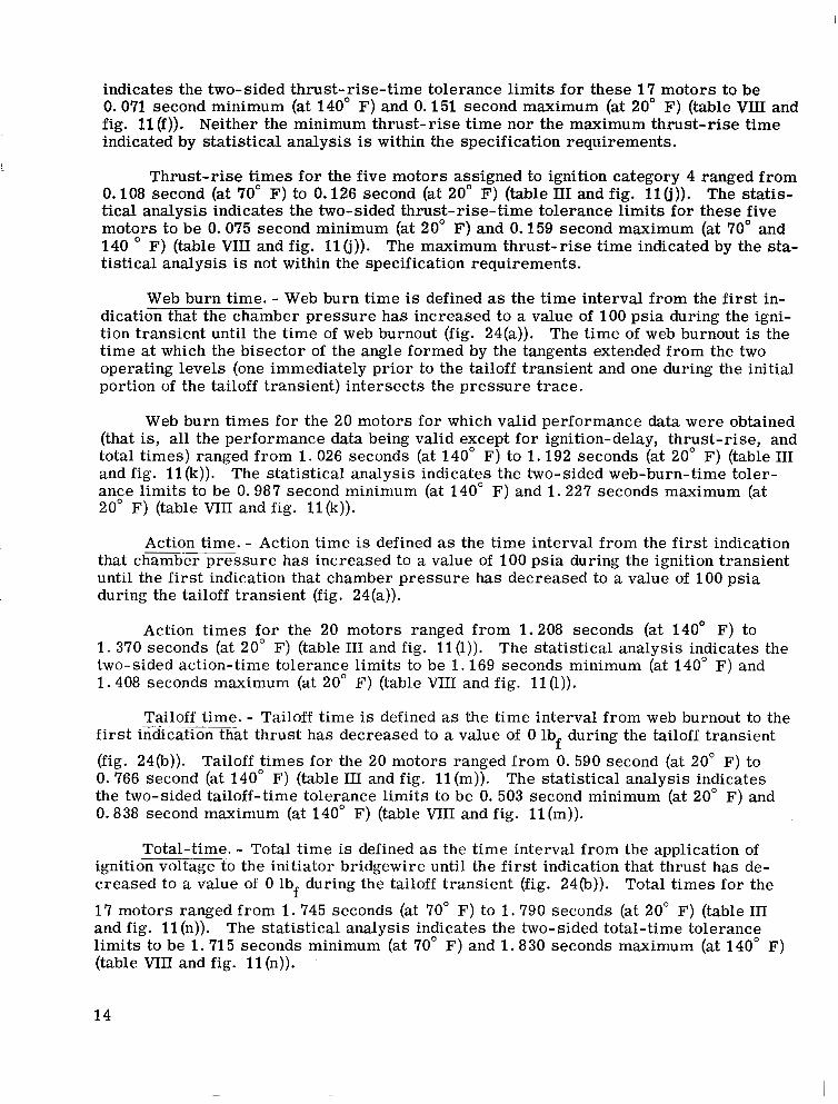
indicates the two-sided thrust-rise-time tolerance limits for these 17 motors to be 0.071 second minimum (at 140" F) and 0.151 second maximum (at 20" F) (table VIII and fig. l l ( f ) ) . Neither the minimum thrust-rise time nor the maximum thrust-rise time indicated by statistical analysis is within the specification requirements.
Thrust-rise times for the five motors assigned to ignition category 4 ranged from 0.108 second (at 70" F) to 0.126 second (at 20" F) (table 111 and fig. 11 (j)). The statis- tical analysis indicates the two-sided thrust-rise-time tolerance limits for these five motors to be 0.075 second minimum (at 20" F) and 0.159 second maximum (at 70" and 140 " F) (table VIII and fig. 11 6)). The maximum thrust-rise time indicated by the sta- tistical analysis is not within the specification requirements.
Web burn time. - Web burn time is defined as the time interval from the first in- dication that the chamber pressure has increased to a value of 100 psia during the igni- tion transient until the time of web burnout (fig. 24(a)). The time of web burnout is the time at which the bisector of the angle formed by the tangents extended from the two operating levels (one immediately prior to the tailoff transient and one during the initial portion of the tailoff transient) intersects the pressure trace.
Web burn times for the 20 motors for which valid performance data were obtained (that is, all the performance data being valid except for ignition-delay, thrust-rise, and total times) ranged from 1.026 seconds (at 140" F) to 1.192 seconds (at 20" F) (table I11 and fig. 11 (k)). The statistical analysis indicates the two-sided web-burn-time toler- ance limits to be 0.987 second minimum (at 140" F) and 1.227 seconds maximum (at 20" F) (table VI11 and fig. l l (k ) ) .
Action time. - Action time is defined as the time interval from the first indication that chamber pressure has increased to a value of 100 psia during the ignition transient until the first indication that chamber pressure has decreased to a value of 100 psia during the tailoff transient (fig. 24(a)).
Action times for the 20 motors ranged from 1.208 seconds (at 140" F) to 1 . 370 seconds (at 20" F) (table I11 and fig. 11 (1)). The statistical analysis indicates the two-sided action-time tolerance limits to be 1 .169 seconds minimum (at 140" F) and 1.408 seconds maximum (at 20" F) (table VI11 and fig. 11 (1)).
Tailoff time. - Tailoff time is defined as the time interval from web burnout to the first indicationthat thrust has decreased to a value of 0 lbf during the tailoff transient (fig. 24(b)). Tailoff times for the 20 motors ranged from 0. 590 second (at 20" F) to 0. 766 second (at 140" F) (table I11 and fig. 11 (m)). The statistical analysis indicates the two-sided tailoff-time tolerance limits to be 0. 503 second minimum (at 20" F) and 0.838 second maximum (at 140" F) (table VI11 and fig. l l ( m ) ) .
Total-time. - Total time is defined as the time interval from the application of ignition voltage to the initiator bridgewire until the first indication that thrust has de- creased to a value of 0 lbf during the tailoff transient (fig. 24(b)). Total times for the
17 motors ranged from 1.745 seconds (at 70" F) to 1 . 7 9 0 seconds (at 20" F) (table III and fig. 11 (n)). The statistical analysis indicates the two-sided total-time tolerance limits to be 1 .71 5 seconds minimum (at 70" F) and 1 .830 seconds maximum (at 140" F) (table VI11 and fig. 11 (n)).
14
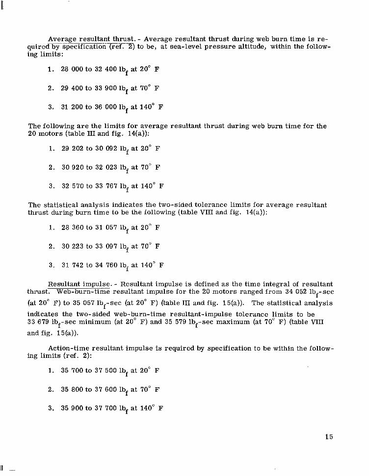
Average resultant thrust. - Average resultant thrust during web burn time is re- q u i r e d b y - ~ p ~ f i c r i ( r e f . - ~ to be, at sea-level pressure altitude, within the follow- ing limits:
1. 28 000 to 32 400 lbf at 20" F
2. 29 400 to 33 900 lbf at 70" F
3. 31 200 to 36 000 lbf at 140" F
The following are the limits for average resultant thrust during web burn time for the 20 motors (table 111 ana fig. 14(a)):
1. 29 202 to 30 092 lbf at 20" F
2. 30 920 to 32 023 lbf at 70" F
3. 32 570 to 33 767 lbf at 140" F
The statistical analysis indicates the two-sided tolerance limits for average resultant thrust during burn time to be the following (table VI11 and fig. 14(a)):
1. 28 360 to 31 057 lbf a t 20" F
2. 30 223 to 33 097 lbf at 70" F
3. 31 742 to 34 760 lbf a t 140" F
Resultant impulse. - Resultant impulse is defined as the time integral of resultant thrust. Web-burn-time resultant impulse for the 20 motors ranged from 34 052 lb sec (at 20" F) to 35 057 lbf-sec (at 20" F) (table I11 and fig. 15(a)). The statistical analysis indicates the two-sided web-burn-time resultant-impulse tolerance limits to be 33 679 lbf-sec minimum (at 28" F) and 35 579 lbf-sec maximum (at 70" F) (table VI11
and fig. 15(a)).
f -
Action-time resultant. impulse is required by specification to be within the follow- ing limits (ref. 2):
1. 35 700 to 37 500 lbf at 20" F
2. 35 800 to 37 600 lbf at 70" F
3. 35 900 to 37 700 lbf at 140" F
1 5
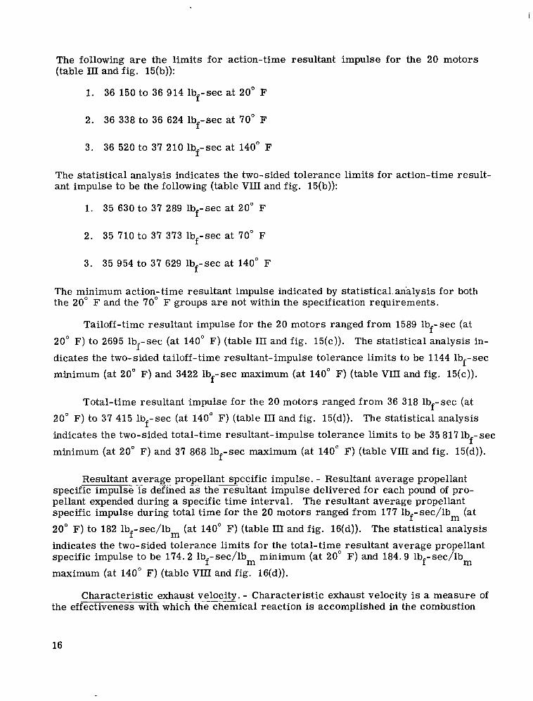
The following are the limits for action-time resultant impulse for the 20 motors (table III and fig. 15(b)):
1. 36 150 to 36 914 lbf-sec at 20" F
2. 36 338 to 36 624 lbf-sec at 70" F
3. 36 520 to 37 210 lbf-sec at 140" F
The statistical analysis indicates the two-sided tolerance limits for action-time result- ant impulse to be the following (table VI11 and fig. 15(b)):
1. 35 630 to 37 289 lbf-sec at 20" F
2. 35 710 to 37 373 lbf-sec at 70" F
3. 35 954 to 37 629 lbf-sec at 140" F
The minimum action-time resultant impulse indicated by statistical.analysis for both the 20" F and the 70" F groups are not within the specification requirements.
Tailoff-time resultant impulse for the 20 motors ranged from 1589 lbf-sec (at
20" F) to 2695 lbf-sec (at 140" F) (table I11 and fig. 15(c)). The statistical analysis in- dicates the two-sided tailoff-time resultant-impulse tolerance limits to be 1144 lbf-sec minimum (at 20" F) and 3422 lbf-sec maximum (at 140" F) (table VIII and fig. 15(c)).
Total-time resultant impulse for the 20 motors ranged from 36 318 lbf-sec (at 20" F) to 37 415 lbf-sec (at 140" F) (table I11 and fig. 15(d)). The statistical analysis indicates the two-sided total-time resultant-impulse tolerance limits to be 35 817 lb sec
minimum (at 20" F) and 37 868 lbf-sec maximum (at 140" F) (table VI11 and fig. 15(d)). f -
Resultant average propellant specific . "" impulse. . .. - Resultant average propellant specific impulse is-defined-as the resultant impulse delivered for each pound of pro- pellant expended during a specific time interval. The resultant average propellant specific impulse during total time for the 20 motors ranged from 177 lbf-sec/lbm (at 20" F) to 182 lbf-sec/lbm (at 140" F) (table 111 and fig. 16(d)). The statistical analysis indicates the two-sided tolerance limits for the total-time resultant average propellant specific impulse to be 174.2 lbf- sec/lbm minimum (at 20" F) and 184.9 lbf- sec/lbm maximum (at 140" F) (table VIII and fig. 16(d)).
Characteristic exhaust velocity. - Characteristic exhaust velocity is a measure of the effectiveness with-whichthe chemical reaction is accomplished in the combustion
16
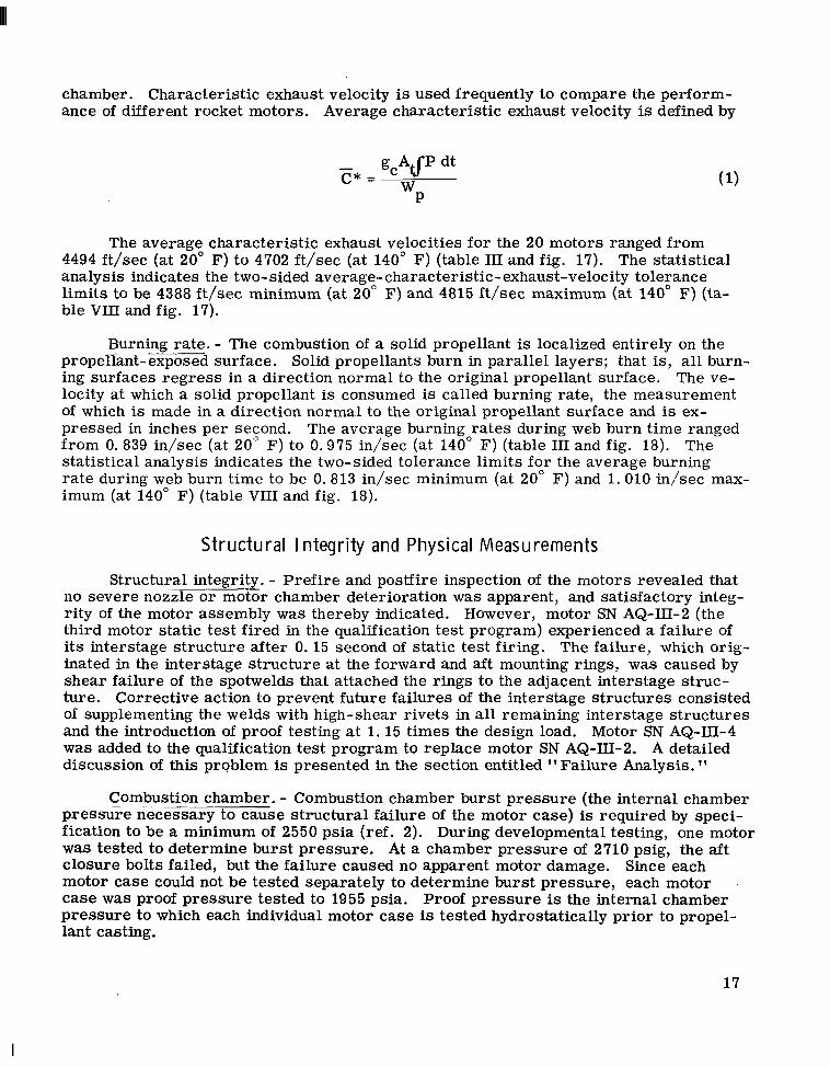
chamber. Characteristic exhaust velocity is used frequently to compare the perform- ance of different rocket motors. Average characteristic exhaust velocity is defined by
The average characteristic exhaust velocities for the 20 motors ranged from 4494 ft/sec (at 20" F) to 4702 ft/sec (at 140" F) (table 111 and fig. 17). The statistical analysis indicates the two-sided average-characteristic-exhaust-velocity tolerance limits to be 4388 ft/sec minimum (at 20" F) and 4815 ft/sec maximum (at 140" F) (ta- ble VIII and fig. 17).
Burning rate. - The combustion of a solid propellant is localized entirely on the propeiiant-exposed surface. Solid propellants burn in parallel layers; that is, all burn- ing surfaces regress in a direction normal to the original propellant surface. The ve- locity at which a solid propellant is consumed is called burning rate, the measurement of which is made in a direction normal to the original propellant surface and is ex- pressed in inches per second. The average burning rates during web burn time ranged from 0.839 in/sec (at 20" F) to 0.975 in/sec (at 140" F) (table I11 and fig. 18). The statistical analysis indicates the two-sided tolerance limits for the average burning rate during web burn time to be 0.813 in/sec minimum (at 20" F) and 1 .010 in/sec max- imum (at 140" F) (table VI11 and fig. 18).
Structural I ntegrity and Physical Measurements
Structural integrity. - Prefire and poslfire inspection of the motors revealed that no severe nozzle o r motor chamber deterioration was apparent, and satisfactory integ- rity of the motor assembly was thereby indicated. However, motor SN AQ-111-2 (the third motor static test fired in the qualification test program) experienced a failure of its interstage structure after 0. 15 second of static test firing. The failure, which orig- inated in the interstage structure at the forward and aft mounting rings, was caused by shear failure of the spotwelds that attached the rings to the adjacent interstage struc- ture. Corrective action to prevent future failures of the interstage structures consisted of supplementing the welds with high-shear rivets in all remaining interstage structures and the introduction of proof testing at 1. 15 times the design load. Motor SN AQ-111-4 was added to the qualification test program to replace motor SN AQ-III-2. A detailed discussion of this problem is presented in the section entitled "Failure Analysis.
Combustion " .. chamber. - Combustion chamber burst pressure (the internal chamber pressure necessary to cause structural failure of the motor case) is required by speci- fication to be a minimum of 2550 psia (ref. 2). During developmental testing, one motor was tested to determine burst pressure. At a chamber pressure of 2710 psig, the aft closure bolts failed, but the failure caused no apparent motor damage. Since each motor case could not be tested separately to determine burst pressure, each motor case was proof pressure tested to 1955 psia. Proof pressure is the internal chamber pressure to which each individual motor case is tested hydrostatically prior to propel- lant casting.
17
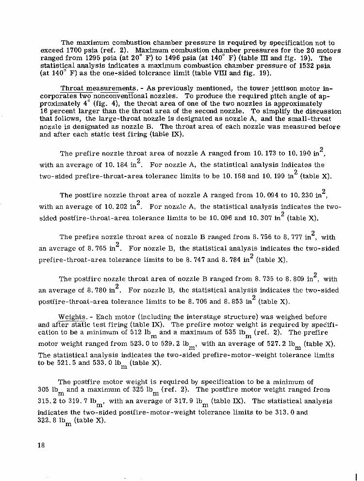
The maximum combustion chamber pressure is required by specification not to exceed 1700 psia (ref. 2). Maximum combustion chamber pressures for the 20 motors ranged from 1295 psia (at 20" F) to 1496 psia (at 140" F) (table III and fig. 19). The statistical analysis indicates a maximum combustion chamber pressure of 1532 psia (at 140" F) as the one-sided tolerance limit (table VIII and fig. 19).
Throat measurements. - As previously mentioned, the tower jettison motor in- corporates two nonconventional nozzles. To produce the required pitch angle of ap- proximately 4" (fig. 4), the throat area of one of the two nozzles is approximately 16 percent larger than the throat area of the second nozzle. To simplify the discussion that follows, the large-throat nozzle is designated as nozzle A, and the small-throat nozzle is designated as nozzle B. The throat area of each nozzle was measured before and after each static test firing (table IX).
The prefire nozzle throat area of nozzle A ranged from 10.173 to 10.190 in , 2
with an average of 10. 184 in . For nozzle A, the statistical analysis indicates the two-sided prefire-throat-area tolerance limits to be 10. 168 and 10. 199 in (table X).
2
2
The posffire nozzle throat area of nozzle A ranged from 10.094 to 10.230 in , 2
with an average of 10.202 in . For nozzle A, the statistical analysis indicates the two- sided postfire-throat-area tolerance limits to be 1.0. 096 and 10. 307 in (table X).
2 2
The prefire nozzle throat area of nozzle B ranged from 8. 756 to 8. 777 in , with 2
an average of 8. 765 in . For nozzle B, the statistical analysis indicates the two-sided prefire-throat-area tolerance limits to be 8. 747 and 8. 784 in (table X).
2
2
The posffire nozzle throat area of nozzle B ranged from 8.735 to 8.809 in , with an average of 8. 780 in . For nozzle B, the statistical analysis indicates the two-sided postfire-throat-area tolerance limits to be 8.706 and 8.853 in (table X).
2 2
2
Weights. - Each motor (including the interstage structure) was weighed before and after static test firing (table IX). The prefire motor weight is required by specifi- cation to be a minimum of 512 lb and a maximum of 535 lbm (ref. 2). The prefire motor weight ranged from 523.0 to 529.2 lb,, with an average of 527.2 lbm (table X).
The statistical analysis indicates the two-sided prefire-motor-weight tolerance limits to be 521.5 and 533.0 lbm (table X).
m
The postfire motor weight is required by specification to be a minimum of 305 lbm and a maximum of 325 lbm (ref. 2). The postfire motor weight ranged from
315.2 to 319. 7 lb,, with an average of 317.9 lb (table IX). The statistical analysis indicates the two-sided posffire-motor-weight tolerance limits to be 313.0 and 322.8 lbm (table X).
m
18
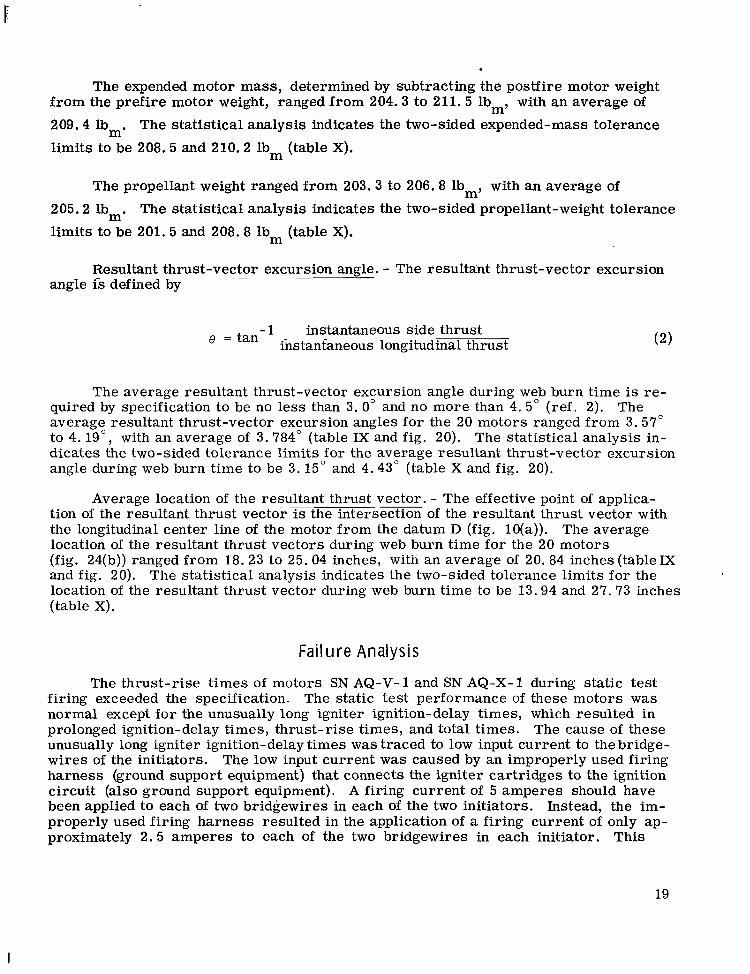
The expended motor mass, determined by subtracting the postfire motor weight from the prefire motor weight, ranged from 204.3 to 211.5 lbm, with an average of 209.4 lbm. The statistical analysis indicates the two-sided expended-mass tolerance limits to be 208.5 and 210.2 lbm (table X).
The propellant weight ranged from 203.3 to 206.8 lb,, with an average of 205.2 lb,. The statistical analysis indicates the two-sided propellant-weight tolerance limits to be 201. 5 and 208.8 lbm (table X).
Resultant thrust-vector excursion angle. - The resultant thrust-vector excursion angle is defined by
e = tan -1 instantaneous side thrust instantaneous longitudinal thrust
The average resultant thrust-vector excursion angle during web burn time is re- quired by specification to be no less than 3. 0" and no more than 4.5" (ref. 2). The average resultant thrust-vector excursion angles for the 20 motors ranged from 3.57" to 4. 19", with an average of 3.784" (table IX and fig. 20). The statistical analysis in- dicates the two-sided tolerance limits for the average resultant thrust-vector excursion angle during web burn time to be 3.15" and 4.43" (table X and fig. 20).
Average location of the resultant thrust vector. - The effective point of applica- tion of the resultant thrust vector is the intersection of the resultant thrust vector with the longitudinal center line of the motor from the datum D (fig. lO(a)). The average location of the resultant thrust vectors during web burn time for the 20 motors (fig. 24(b)) ranged from 18.23 to 25. 04 inches, with an average of 20. 84 inches (tableIX and fig. 20). The statistical analysis indicates the two-sided tolerance limits for the location of the resultant thrust vector during web burn time to be 13.94 and 27. 73 inches (table X).
Failure Analysis
The thrust-rise times of motors SN AQ-V-1 and SN AQ-X-1 during static test firing exceeded the specification. The static test performance of these motors was normal except for the unusually long igniter ignition-delay times, which resulted in prolonged ignition-delay times, thrust-rise times, and total times. The cause of these unusually long igniter ignition-delay times was traced to low input current to thebridge- wires of the initiators. The low input current was caused by an improperly used firing harness (ground support equipment) that connects the igniter cartridges to the ignition circuit (also ground support equipment). A firing current of 5 amperes should have been applied to each of two bridgewires in each of the two initiators. Instead, the im- properly used firing harness resulted in the application of a firing current of only ap- proximately 2.5 amperes to each of the two bridgewires in each initiator. This
19
I

condition was corrected for all subsequent testing by fabricating two special firing har- nesses. One of these firing harnesses was used for static test firings of motors as- signed to ignition categories 1 and 3, of which both duplicated a failed igniter cartridge; the other special firing harness was used for static test firings of motors assigned to ignition categories 2 and 4, of which both duplicated normal igniter ignition conditions. Because the failures of motors SN AQ-V-1 and SN AQ-X-1 were a direct result of im- properly used ground support equipment rather than the result of a motor malfunction, the ignition-delay times, thrust-rise times, and tbtal times obtained from these motors were deleted from the performance evaluations.
The thrust-rise time of motor SN A&-VIII- 1 during static test firing also ex- ceeded the specification. The static-test-firing performance of this motor was normal except for an unusually long igniter ignition-delay time, which resulted in prolonged ignition-delay, thrust-rise, and total times. A thorough check of the electrical and instrumentation systems confirmed that the proper firing current, cartridge resist- ances, and igniter harness were used. The precise cause of this failure could not be determined from the available information; however, the following were regarded as possible factors contributing to the malfunction.
1. Inert debris from the igniter cartridge
2. Relatively small-diameter flame ports (fig. S(a)) in the igniter case
3. Premature expulsion of the booster powder charge from the igniter cartridge
4. Deflection of the igniter cartridge flame by the igniter cartridge closures into the heat-sink area of the igniter case
The corrective action included modification of the igniter assembly to permit greater tolerance for the debris associated with the igniter cartridge. The diameter of the flame ports in the igniter case were enlarged from 0.375 to 0.500 inch to pre- clude passage blockage. The two-layer vinyl tape cover on the boron-potassium nitrate pellet container was reduced to a single-layer tape cover to permit easier tape burnthrough. These modifications were effected for test motor assemblies SN AQ-V-2 and SN A&-E- 1.
Following the completion of the tower jettison motor qualification test program, an igniter t e s t program was conducted by which it was verified that the igniter modifications were successful (ref. 4). It should be noted, however, that the Apollo Spacecraft Program systems are required to demonstrate success following only a single failure. The malfunction of motor SN A&-VIII-1 occurred during the time that the motor was duplicating a double failure mode (a failed initiator cartridge and a failed nozzle closure), and the tower jettison motor is not required to demonstrate success under these conditions. Because the igniter assembly was modified and because a dou- ble failure mode was being duplicated, the ignition-delay, thrust-rise, and total times obtained during testing of motor SN AQ-VIII- 1 were deleted from the performance evaluation.
Failure of the interstage structure of motor SN AQ-111-2 (the third motor static test fired) during static test firing caused the subsequent destruction of the motor assembly. The failure, which originated at the interstage structure forward and aft
20
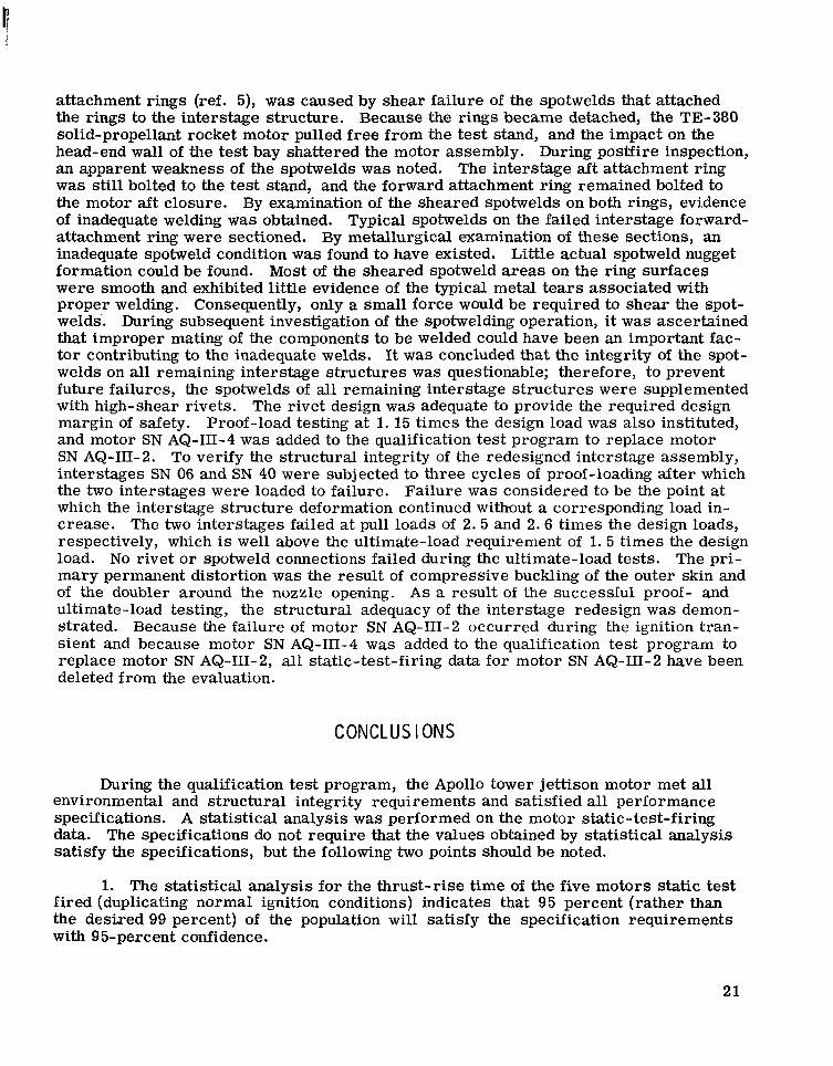
attachment rings (ref. 5), was caused by shear failure of the spotwelds that attached the rings to the interstage structure. Because the rings became detached, the TE-380 solid-propellant rocket motor pulled free from ihe test stand, and the impact on the head-end wall of the test bay shattered the motor assembly. During postfire inspection, an apparent weakness of the spotwelds was noted. The interstage aft attachment ring was still bolted to the test stand, and the forward attachment ring remained bolted to the motor aft closure. By examination of the sheared spotwelds on both rings, evidence of inadequate welding was obtained. Typical spotwelds on the failed interstage forward- attachment ring were sectioned. By metallurgical examination of these sections, an inadequate spotweld condition was found to have existed. Little actual spotweld nugget formation could be found. Most of the sheared spotweld a reas on the ring surfaces were smooth and exhibited little evidence of the typical metal tears associated with proper welding. Consequently, only a small force would be required to shear the spot- welds. During subsequent investigation of the spotwelding operation? it was ascertained that improper mating of the components to be welded could have been an important fac- tor contributing to the inadequate welds. It was concluded that the integrity of the spot- welds on all remaining interstage structures was questionable; therefore, to prevent future failures, the spotwelds of all remaining interstage structures were supplemented with high-shear rivets. The rivet design was adequate to provide the required design margin of safety. Proof-load testing at 1. 15 times the design load was also instituted, and motor SN AQ-III-4 was added to the qualification test program to replace motor SN AQ-111-2. To verify the structural integrity of the redesigned interstage assembly, interstages SN 06 and SN 40 were subjected to three cycles of proof-loading after which the two interstages were loaded to failure. Failure was considered to be the point at which the interstage structure deformation continued without a corresponding load in- crease. The two interstages failed at pull loads of 2 . 5 and 2 . 6 times the design loads, respectively, which is well above the ultimate-load requirement of 1. 5 times the design load. No rivet o r spotweld connections failed during the ultimate-load tests. The pri- mary permanent distortion was the result of compressive buckling of the outer skin and of the doubler around the nozzle opening. A s a result of the successful proof- and ultimate-load testing, the structural adequacy of the interstage redesign was demon- strated. Because the failure of motor SN AQ-III-2 occurred during the ignition tran- sient and because motor SN AQ-111-4 was added to the qualification test program to replace motor SN AQ-111-2, all static-test-firing data for motor SN AQ-III-2 have been deleted from the evaluation.
CONCLUSIONS
During the qualification test program, the Apollo tower jettison motor met all environmental and structural integrity requirements and satisfied all performance specifications. A statistical analysis was performed on the motor static-test-firing data. The specifications do not require that the values obtained by statistical analysis satisfy the specifications, but the following two points should be noted.
1. The statistical analysis for the thrust-rise time of the five motors static test fired (duplicating normal ignition conditions) indicates that 95 percent (rather than the desired 99 percent) of the population will satisfy the specification requirements with 95-percent confidence.
21

2. The statistical analysis for the action-time resultant impulse of the 20 motors static test fired also indicates that 95 percent (rather than the desired 99 percent) of the population will satisfy the specification requirements with 95-percent confidence. '
The product variance of the thrust-rise time will have only a negligible effect on the performance of the launch escape system because the product variance of the worst case indicates that the tower jettison motor will reach 90 percent of maximum thrust only 0.009 second in excess of the specification requirement of 0.150 second. The product variance of the action-time resultant impulse for the 20 motors static test fired will have only a negligible effect on the performance of the launch escape system. From the results of the qualification test evaluation, it was confirmed that the tower jettison motor is. qualified for the Apollo Spacecraft Program because the motor will jettison the launch escape system safely from the command module and out of the com- mand module path either shortly after the launch vehicle second-stage ignition and staging or during a mission abort.
Manned Spacecraft Center National Aeronautics and Space Administration
Houston, Texas, March 11, 1970 914-50-60-01-72
REFERENCES
1. Anon. : Qualification Test Program Final Report, August 1964 to May 1965 (U). Doc. No. A-027, Thiokol Chemical Corp. , Elkton Division, Sept. 29, 1965.
2. Anon. : Rocket Motor, Tower Jettison, Launch Escape System (U). Specification, Doc. No. MC 467-0001# F, North American Aviation, Inc. , Space and Informa- tion Systems Division, July 28, 1964.
3. Lee, B. J. ; and Burchfield, P. B. : Solid Propellant Rocket Motor Performance Computer Programs Using the Group Transformation Method. NASA T N D-3667, 1966.
4. Anon. : Apollo Tower Jettison Program Monthly Progress Report Number 32 (U). Doc. No. A-232, Thiokol Chemical Corp. , Elkton Division, Apr. 15, 1965.
5. Anon. : Apollo Tower Jettison Program Monthly Progress Report Number 31 (U). Doc. No. A-231, Thiokol Chemical Corp. , Elkton Division, Mar. 15, 1965.
22
I'
TABLE I. - PROPELLANT FORMULATION FOR
THE APOLLO TOWER JETTISON MOTOR
(a) Composition
r Ingredient
Ammonium perchlorate, NH4C104 Aluminum powder, A1 Polysulfide polymer, LP- 33 Benzyl mercaptan, C6H5CH2SH p-quinonedioxime, GMF
Sulfur, S
Magnesium oxide, MgO Ferr ic oxide, Fe203 Dibutyl-carbital, TP-903 Diphenyl guanidine, DPG
I 1 Function Weight,
percent
Oxidizer Fuel Fuel/binder Curing accelerator Curing agent Curing agent Curing accelerator Burning- rate catalyst Plasticizer Curing agent
72.00 2.00
18.81
( 4 1.39 . 01
1.00 2.00 2.09 .70
aTo obtain specific physical properties, the amount of benzyl mercaptan may be varied between 0.00 and 0.09 percent by direct substitution for a like percentage of polysulfide polymer.
(b) Properties
.. - ....
Exhaust gas specific heat ratio, y . . . . . . . . . . . . . . . . . . . 1.176 Propellant density, p, lbm/in 3 . . . . . . . . . . . . . . . . . . . . . 0.0633 Autoignition temperature Ta, O F :
1 h r . . . . . . . . . . . . . . . . . . . . . . . . . . . . . . . . . 355 8 h r . . . . . . . . . . . . . . . . . . . . . . . . . . . . . . . . . 320
Flame temperature at 1000 psia, Tf, O F . . . . . . . . . . . . . . . 4404 - ~ "" . - ""
23
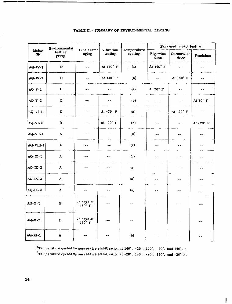
TABLE II. - SUMMARY OF ENVIRONMENTAL TESTING
Motor SN I Environmen
testing group
AQ-IV-1 D
AQ-IV-2 D
AQ-V-1 C
AQ-V- 2 C
AQ- VI- 1 D
AQ-VI-% D
AQ-Vn-1 A
AQ-VIII-1
AQ-E-2
4Q-X-1 B
I IQ-X-2 B
Vibration testing
___-
At 140" F _ _ _ ~ ~ - .
At 140" F _ _ _ _
"
___~"
"
At -20" F
cycling Temperature
~
-I- ~ ~. " . .~
Packaged impact testing
Edgewisc drop
At 140" E
~"
- ~-
"
.~
At 70" F
- ~
Cornerwisl drop Pendulum
"" " ~
"
" ""
"
"
" ~
At 70" F
"
.~
At -20" F ~
aTemperature cycled by successive stabilization at 140", - Z o o , 140", -20". and 140" .F. bTemperature cycled by successive stabilization at -20", 140", -20", 140°, and -20" F.
24
I
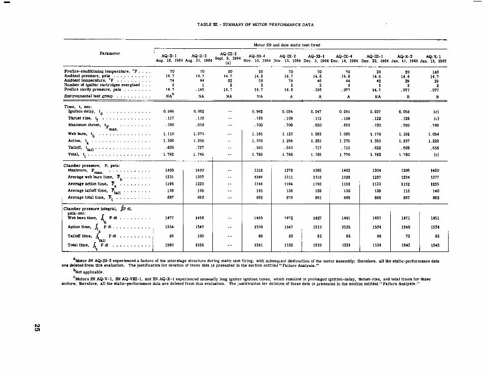
TABLE Ill. - SUMMARY OF MOTOR PERFORMANCE DATA
Motor SN and date static test flred
Parameter ' AQ-II-1 AQ-II-2 AQ-m-2 AQ-III-4 AQ-JX-2 AQ-XI-1 AQ-M-4 AQ-Ill-1 AQ-X-2 AQ-X-1 Aug. 18, 1964 Aug. 31, 1964 :) 1964 Nov. 10, 1964 Nov. 13, 1964 Dec. 3, 1964 Dec. 14, 1964 Dec. 22, 1964 Jan. 11. 1965 Jan. 13, 1965
Preflre-conditloning temperature, " F Ambient pressure, p s i
IO IO 20 . . . . . . . . . . . 14. I 14. I 14. I 14.8 Amblent temperature, "F . . . . . . . . . . . 74 84 82 Number of Igniter cartridges energized 2 Prefire cavity pressure, p s i
1 14. 7
2 . . . . . . . . ,145 14. I 2
Environmental test group . . . . . . . . . . N A ~ NA NA NA A A A NA B
~ ~~~~~
. . . . 20 I O I O IO 20 20 140 14.8 14.8 14.8 14.8 14. I
58 1 4 46 44 42 29 29 2
14.6 ,156 . 011 14. I ,011 . 011 2
B
14. I
2 2 . . . 14. I
2 1
L
Time, 1, sec: Ignition delay, td . . . . . . . . . . . . . 0.046 0.062 "
Thrust rlse, tr . . . . . . . . . . . . . . ,111 ,110 "
Maximum thrust, t . . . . . . . . . . IO0 ,650 "
Webburn, $, . . . . . . . . . . . . . . . 1.110 1.073 "
Action, t . . . . . . . . . . . . . . . . . 1.300 1.268 "
Tailoff, thil . . . . . . . . . . . . . . . . ,630 ,121 "
Fmuc.
Total, tt . . . . . . . . . . . . . . . . . . 1.762 1.145 "
-c Chamber pressure, P, psla:
Maxlmum, Pa, . . . . . . . . . . . . 1400 Average web burn time, Fb . . . . . . . . 1331
Average action time, pa . . . . . . . . . 1195
Average tailoff time, Ftail . . . . . . . . 136 , Average total time, Ft . . . . . . . . . . 887 1
1430 1351
1220
138 892
"
"
"
"
"
1 %-Etn time: P dt 1 :;;:
' Chamber pressure integral, JP dt,
1 . . . . . . . . . Action time, P d t . . . . . . . . . . . Tailoff time, P dt . . . . . . . . . 86
Totaltime, $ P d t . . . . . . . . . . . 1563 ttail
1456
" 1556
" 100
" 1541
"
0.042 0.034 0.041 0.041 0.031 0.058 ( 4 . 126 ,108 ,112 ,108 ,122 ,126 (C) . I00 . IO0 ,650 ,650 . IO0 .700 , 7 0 0
1.165 1.123 1.083 1.085 1.178 1.192 1.054
1.338 1.296 1.263 1.279 1.353 1.331 1.222 .593 ,643 . I11 . I15 .622 ,608 .658
1. 188 1. 188 1.165 1.170 1.782 1. I80 (C)
1318 1249
1144
145 862
1455
1530
86
1541
1310 1385 1402 1304 1306 1450 1311 1318 1328 1231 1234 1311 1194 1198 1192 ' 1133 1152 1255
130 128 130 139 118 140 810
~ 861 ~ 866 ~ 866 ~ 861 89 2
1412
1534 1540 1534 1525 1513 1547
1451 1411 1451 1441 1421
83 , 92 72 86 93 92
1555 1543 1543 1534 1531 1519
are deleted from thls evaluation. The justification for deletion of these data is presented in the section entitled "Failure Analysis." 'Motor SN AQ-III-2 experienced a failure of the interstage structure during static test firing, with subsequent destruction of the motor assembly; therefore, all the static-performance data
%ot applicable. 'Motors SN AQ-V-1, SN AQ-MI-1, and SN AQ-X-1 experienced unusually long igniter ignition times, which resulted in prolonged ignition-delay, thrust-rise, and total times for these
motors; therefore, all the statlc-performance data are deleted from this evaluation. The justification for deletion of these data is presented in the section entitled "Failure Analysis."
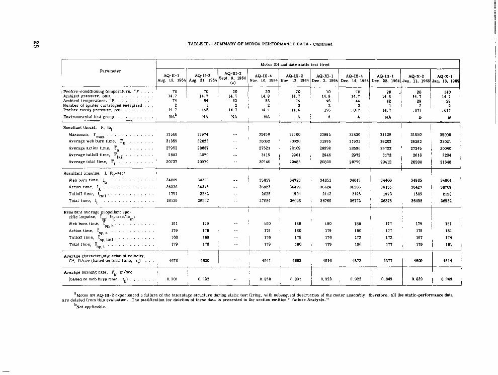
L\3 0)
TABLE In. - SUMMARY OF MOTOR PERFORMANCE DATA - Continued
Motor SN and date static test fired Parameter
AQ-11-1 Jan. 13. 1965 Jan. 11, 1965 Dec. 22. 1964 Dec. 14, 1964 Dec. 3. 1964 Nov. 13, 1964 Nov. 10. 1964 ::, 1964 Aug. 31, 1964 Aug. 18. 1964
AQ-X-1 AQ-X-) AQ-m-1 AQ-IX-4 AQ-XI-1 AQ-IX-2 AQ-111-4 AQ-11-2
IPrefire-conditioning temperature, "F . . . . 14 .1
147: I 70 70 20 . 20 Ambient pressure, psia . . . . . . . . . . . 14.7 1 14;; 1 14;i 1 14.7 '' 140
Ambient temperature. 'F . . . . . . . . . . 74 84 82 ' 58 74 46 44 Number of igniter cartridges energized . . .
29
Prefire cavity pressure, psia . . . . . . . . 14.7 14. 7 14.6 1
. 145 14. 7 2 2
,156 ,077 , 14.1 2
,077 ,077 2 2 1 2 2 . ' 1
Environmental test group . . . . . , . . . . , NAb NA NA , NA ' ~ i A A NA 1 B B
Resultant thrust, F, Ibf: I I I , j t
Maximum, Fmax, . . , . . . . , . . . . . 33500 33974 " 32450 32700 33895 33830 i 31129 1 31050 ~ 35000 Average web burn time. Fb . . . . . . . 31359 32023 " ' 30092 ' 30920 31995 31933 29202 29283 ! 33021 Average action time, F . . . . . . . . . 27952 28687 " 27521 , 28109 28998 28590 I 26722 I 21245 I 30040 Average tailoff time, Ttai, . . . . . . . . 2843 3070 " 3415 I 2961 , 2946 2972 , 3172 2613 ' 3234
Average total time, f t . . . . . . . . . . ' 20737 20970 " 20740 I 20485 ' 20830 20776 20412 ~ 20504 ~ 21348
- -
I 1 I I
Resultant impulse, 1. Ibf-sec: I
"I
Webburn time, I,, . . . . . . . . . . . . 34809 34361 - - 1 35051 ~ 34723 ! 34651 34647 1 34400 1 34905 34804 '
Action time, la , . . . . . . . . . . . . . 36338 36375 " 36823 36429 36624 36566 36155 1 36427 I 36709 Tailoff time, Itail . . . . . . . . . . . . . 179 1 2232 " 2025 1904 2112 2125 1913 1589 I 2128 Total time, It . . . . . . . . . . . . . . 36539 36593 " 37084 36628 , 36765 36173 ' 36375 , 36498 , 36932
Resultant average propellant spe-
181 179 "
I I , I 1 I
I I 180 ' 180 I 180 180 177 179 181 ,
Action time, Isp, a . . . . . . . . . . . . 179 178 " 179 ' 180 179 180 I 177 ' 179 ' 181 Tailoff time, Isp, tail . . . . . . . . . . . 160 169 176 , 175
Total time, Isp, . . , , . , , , . , . . , 179 178 ' " " I 179 ; 180 I 179 180
P*, ft/sec (based on total time, tt) . . . 4670 4620 1 - - , 4541 1 4663 i 4516 4572 4577 4609 4614
L____" , I 1
Average characteristic exhaust velocity, 1 I 1
Average burning rate, rb, in/sec I
! ! i (based on web burn time, 5) . . . . . . . 0.901 0.932 , " ~ 0.858 ~ 0.891 i 0.923 0.922 I 0.849 I 0.839 I 0.949 ~
a r e deleted from this evaluation. The justification for deletion of these data is presented in the section entitled "Failure Analysis." aMotor SN AQ-111-2 experienced a failure of the interstage structure during static test firing, with subsequent destruction of the motor assembly: therefore, all the static-performance data
bNot applicable.
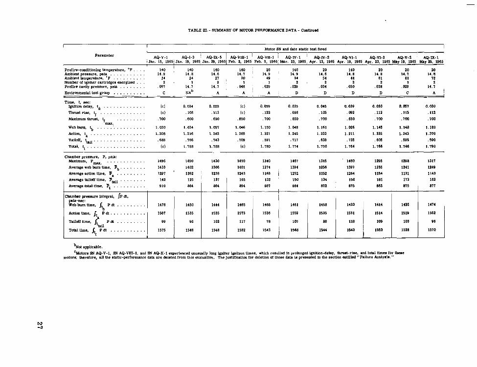
TABLE m. - SUMMARY OF MOTOR PERFORMANCE DATA - contirmed
I I Motor SN and date static test fired I
Parameter AQ-V-1 I AQ-1-3 ! AQ-M-3 I AQ-MI-1 AQ-VII-1 AQ-I"-1 AQ-lV-2 ' AQ-VI-1 AQ-VI-2 AQ-V-2 ~ AQ-E-1 ~Jan. 15. 19651 Jan. 19. 1965 Jan. 29. 19651 Feb. 2. 1965, Feb. 9. 19651 Mar. 25. 1965 A m . 13. 1965 ADr. 19. 1965 A m . 23. 1965 Mnv 19. 1965 Mnv 25. 1965
Prefire-conditioning temperature, "F . . . . 140 ' 140 140 Ambient pressure, psia . . . . . . . . . . . 14.9 14.8 14.6
140 ' 20 140 20 140 20 20 20 14.1 ' 14.9 ' 14.9
Ambient temperature, 'F . . . . . . . . . . 14 24 27 30 ' 49 14.8 14.8 14. I 14.8
Number of igniter cartridges energized 34
. . . 2 , 1 54 44 61 81 I2
1 Prefire cavity pressure, psia . . . . . . . . ,011 14. I 14.1 , ,048 I ,029 , ,029
2 , ,034
2 2 1 2 ,050
2 ,038 ,028 14. I
Environmental test group . . . . . . . . . . C N A ~ A A ' A : D D D D C A I
Time, t, see:
14.6
2 : 1
1 - 1
Ignition delay, td . . . . . . . . . . . . . (C) 0.034 0.028 (c) 0.059 0.035 0.045 0.039 0.050 0.051 0.030 Thrust rise, tf . . . . . . . . . . . . . . (C) ,108 ,113 (C) ,122 ,086 ,105 ,092 ,112 ,115 ,112 Maximum thrust, tf . . . . . . . . . . loo ,600 ,650 .E50 . loo .650 .loo ,650 .loo .loo .loo
Webburn, $, . . . . . . . . . . . . . . . . 1.030 1.034 1.051 1.046 1.150 1.048 1.161 1.026 1.145 1.148 1.180 Actim, t . . . . . . . . . . . . . . . . . 1.208 1.216 1.242 1.265 1.321 1.245 1.333 1.211 1.335 1.343 1.310 Tailoff, thu. . . . . . . . . . . . . . . . ,688 .I66 ,143 . 109 . 591 .I11 .639 .I35 .605 f595 .590 Total, tt . . . . . . . . . . . . . . . . . . (C) 1. I88 1.788 (C) 1.180 1.114 1.170 1.164 1.166 1.146 1. I90
m u .
Chamber pressure, P, psia: Maximum, P-. . . . . . . . . . . . . 1496 1490 1430 1410 1340 1461 1315 ' 1460 1295 1298 1311 Average web bun time, pb . . . . . . . . 1433 1402 1366 1401 1214 1394 1256 1391 1235 1241 1249 Avenge action time, Fa . . . . . . . . . 1291 . 1262 1236 1243 1163 ~ 1252 1152 1264 1134 1191 1140 Average tnildf time, YUil . . . . . . . . 143 125 '
811 815 863 815 ' 861 884 ~ 812 894 864 Average totnl time, Yt . . . . . . . . . . 910 864 165 , 132 150 134 150 181 113 162 131
I I
Chamber pressure integral, JP dt,
Web burn time, psia-see:
Action time, jt P dt . . . . . . . . . . . 1561 1535
1510 1528 1523 1543 1544 1568 1543 1582 1546 1546 1515 Total time, j P d t . . . . . . . . . . . 96 103 109 110 86 101 I 8 111 102 D6 99 Tailofi time, P d t . . . . . . . . .
1562 1519 1514 1531 1535 1559 1536 1513 1535 tb P d t . . . . . . . . .
1414 1425 1414 1433 1456 1461 1465 1465 1444 1450 1416
a
ttail
tt
%or applicable. 'Motors SN AQ-V-1, SN AQ-MI-1, and SN AQ-X-1 experienced unusually long igniter ignition times, which resulted in prolonged ignition-delay, thrust-rise. and total times for these
motors; therefore, all the static-Performance data are deleted from this evaluation. The justification for deletion of these data is presented In the section entitled " Failure Analyeis. "
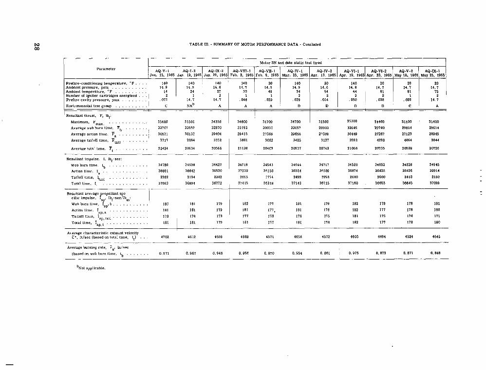
TABLE III. - SUMMARY OF MOTOR PERFORMANCE DATA - Concluded
Parameter
Prefire-conditioning temperature, " F . . . . Ambient temperature, " F . , . . . . . . . . Number of igniter cartridges energized . . . Prefire cavity pressure, psia . . . . , . . . ,017 14. 7 14. I Environmental test group . , . . . , . . . . C N A ~ A
Resultant thrust, F, Ibf: Maximum, Fmax, . . . . . . . . . . ... 35400 35500 34250 Average web burn time, F . . . , . . . 33161 33557 32510 Average action time, F . . . . , . . . . ~ 30531 30133 29404 Average tailoll time, ftaii . . . . . . . . ' 3317 2864 3152
Average total time, Ft . . . . . . . . . . 21424 20634 20566
Resuitant impulse. 1. ibl-sec: Web burn time. Ib . . . . . . . . . . . . Action time, la . . . . . . . . . . . . . . Tailoff time, ltail . . . , . . . . . . . . Total time, I, . . . . . . . . . . . . . .
-1
Resuitant average_propeiiant spe- cific impulse, Isp. Ibf-sec/lbm: Web burn time, IC,>, b , . . . . . . . . . . Action time, is,, a . . . . . . . . . . . Tailofl time, isp, . . . . . . . . . . Total time, isp, . . . . . . . . . . . .
-r
34780 36881 2282
31063
34698 34421 36642 36520 2194 2342
36894 36112
182 181 178 181 I
181 119 181 119 114 113 181 119
Motor SN and date static test fired
AQ-VIII-1 May 25, 1965 May 19, 1985 Apr. 23, 1985 Apr. 19, 1965 Apr. 13, 1965 Mar. 25, 1965 Feb. 9, 1965 eb. 2, 1965
AQ-M-I AQ-V-2 AQ-VI-2 AQ-VI-I AQ-IV-2 AQ-IV-1 AQ-VII-1
140 14. I
20 14.9
140 14.9
20 14.6
140 14.8
20 14. I
20 14. I
20 14. I
A A ' D D ' C i A I
34600 31100 34100 33192 30031 33051
31500 35300 31400 31100 ' 31400
27389 30449 27281 21123 26945 29415 27366 29658 29903 33645 29740 29814 29614
3801 3002 3485 3121 3592 4298 4064 3644
21138 20403 20931 20743 21066 20155 20988 20126
34719 34543 34644 34117 34520 34052 34226 34945 37210 36150 36924 36509 36874 36428 36426 36914 2695 1714 2499 1998 2640 2600 2418 2150
37415 36318 31143 361 15 31160 , 36653 36645 31W9
182 111 181 119 182 118 178 181 181 111. 181 118 182 111 118 180 111 110 118 115 181 115 174 171 181 111 181 118 182 111 118 180
Aberage characteristic exhaust velocity I c*, ft/sec (based on total time, tt) . . . 4702 ~ 4612 4589 4668 4511 4658 4512 4603 4494 4524 4645
______ Average turning rate, Tb. in/sec
(based on web burn time, t,, . . . . . . . 0.971 0.961 0.946 0.956 0.870 0.954 0,861 0.975 0.813 0.871 0.848 ~ _ _ _
bNot applicable.
TABLE IV. - STATIC TEST INSTRUMENTATION
system accuracy Measuring Range of
device Parameter measuring Recording
device i Steady device ! state at Integral,
Method of system calibration
operating percent level
I
Axial force, lbf a+ 0.25 " j Bonded strain- 0 to 50 000 lbf Multiinput high- 1 Hydraulically actuated a t nominal """"""""""_ """""_I """"" I gage-type load speed analog- ' lbads of 0, 10 000. 20 000,
I cell ' to-digital ; 30 000, and 40 000 lbf I Total impulse, " j t0.33 ,
lbf -sec 1 I 1 converter
I
, Forward side force, ai 0.24 -- ' Bonded strain- 0 to 2000 lbf , Multiinput high- Hydraulically actuated a t nominal
lbf gage-type load , i speed analog- loads of 0, 500, 1000, 1500,
a
, cell I to-digital and 2000 lbf I converter 1-
Motor chamber I T 0.16 I - - Bonded strain- 0 to 2000 psia Multiinput high- Electrical calibration at nominal
pressure, psia ~ gage-type speed analog- levels of 0, 500, 1000, 1500, ""_"""""""" """""_ """"" transducers to-digital ' and 2000 psia Chamber pressure " t 0 . 3 3 converter
integral, psia-sec
Aft side force, lbf a r3 . 3 " Bonded strain 0 to 500 lbf Multiinput high- Hydraulically activated a t nomi- gage-type load speed analog- nal loads of 0, 125, 250, cell to-digital ' 375, and 500 lbf
, 1 converter I
Time intervals Compared with 60 amps Photographically " Synchronous " b+ 0.1 timing line generator
recording galvanometer- type oscillo- graph
apercent. bMilliseconds.
01 W

w 0 TABLE V. - VARIATION OF MOTOR PERFORMANCE AS A FUNCTION OF MOTOR OPERATING TIME TRANSFORMED TO
A PREFIRE-CONDITIONING TEMPERATURE OF 20" F AND THE TWO-SIDED TOLERANCE LIMITS
(a) Chamber pressure
- PEHCENT - PERCENT - YEINS WITH TWO-SIDE@ TOLFRANCE LIMITS - - #E9 BURN - TAILOFF - T R A N S F O R W I T I M E S P S E C - TRANSFORMEP CHAMBER PRESSUREPPSII - - T I q E - T I 4 E - MEAN - MINIHUY - M A X I Y U M
- - . . . . . . . . . . . . . . . . . . . . . . . . . . . . . . . . . . . . . . . . . . . . . . . . . . . . . . . . . . . . . . . . . . . . . . . . . . - - "_"""""~"""""""~"""~""~""""""~~""""-~""""~"-"-"""-----""""~-"-~ - MEAN - YIVIMUY - MAXIMlIu - . . . . . . . . . . . . . . . . . . . . . . . . . . . . . . . . . . . . . . . . . . . . . . . . . . . . . . . . . . . . . . . . . . . . . . . . . . . . . . . . .
.oo
1.56 .78
2.34 3.12 3.91 U.69 5.47 6.25 7.03 7.81 8.59
10.16 9.57
10.94 11.72 12.50 13.28 14.06 14.84 15.62 16.41 17.19 17.97
i9.53 20.31 21.09 21.87 22.66 23.44 24.22 25.00 25.78 26.56 27.34 28.12 28.91 29.69 30.47 31.25 32.03 32.81
18.75
0 0 0 0 0 0 0 0 0 0 0 0 0 0 0 0 0
0 0
0 0 0 0 0 0 0 0 0 0
0 0
0 0 0 0 0 0 0 0 0 0 0 0
.ooooo 00864 -01728 e02592 .OW56 .04320 .OS184 .Oh048 .Oh912 .07776 ,08640 .09504 -10368 -11232 ,12096 ,12960 .13824 .lU68R .15552 .16416 .172flO .18144 .I9008 .19872 ,20736 ,21600 ,22464 ,23328 ,24192 e25056 .25920 ,26784
,28512 e29376 -30240 ,31104
-32832 -3 1968
e33696 -34560 35424 36288
,27648
.ooooo ,00956 e01912
.03824 ,02868
,04781 05737 06693 07649 -08605 ,09561 -10517 -11473 -12429 -13386 ,14342 15298 -16254 .I7210 e18166 ,19122 -20078 -21034 e21991 ~22947 -23903 -24859 -25815 e26771 .27727 -28683 29639 -30595
-32508 -31552
e33464 34420
-36332 e35376
,37288 e38244 -39200 -40157
260.15S6 - 100.53P7 - 438.7600 - 622.0118 - 797.81336 - 950.0211 - 1151.0452 - lfl66.8119 - 1207.3601 - 121t6.0335 - 1270.lSP8 - 1293.0780 - 1296.9331 - 1299.0141 - 1299.7598 - 1798.8957 - 1297.33b6 - 1295.5245 - 1293.7579 - 1293.2178 - 1292.5854 - 1292.7520 - 1292.3065 - 1291.7836 - 1291.5652 - 1291.2913 - 1289.3441 - 1286.0201 - 1276.9963 - 1201.5866 - 1273.0168 - 1266.7651 - 1265.4667 - 1266.5205 - 1269.2173 - 1267.8264 - 1270.4855 - 1272.42@1 - 1274.87A3 - 1277.8522 -
12~5.1707 -
1269.41744 - 1265.7402 -
.ooon -
.no017 -
.noon -
.onon - 130.7186 - b14.9410 - 593.7573 - 1033.5293 - P93.976? - 1127.5799 - 1187.2790 - 1225.9984 - 1230e6908 - 1230.5453 - 1229.7833 - 1328.9051 - 1230.5075 - 1729.6935 - 1?29.7957 - 1231.4355 - 1231.9616 - 1234.5594 - 1735.9403 - 1735.8681 - 1334.3449 - 1233.6114 - 1223.6637 - 1229.9687 -
1212.n6n4 -
1316.729n - 1P10.7647 - 1207.3114 - 1205.3310 - 1202.1809 - 1203.2972 - 1202.6303 - 1205.3909 - 1207.5357 - 1209.2736 - 1210.4620 - 1211.2104 - 1213.2131 - 1215.6812 -
682.2ROP 105.7746
10RP.8585
1469.8886 1485.1013 1439.8665 1408.2143
1364.4871 1353.1186 135R.281n 1360.657q 1363.32@0 1367.3374 1369.7364 136R.RPh3
134~.nl(nn
13~2.391-10
1364 9797, 136n.S41* 1357.720P 1355.0001
1350.9447 1348.6737 1347.6991 1348.7856
1399.2196 1348.5766 1346.4445 1343.227A
1333.Q777
1355.2091
1348.9713
1338.7221
L330.2530
1327.65n1
1329.161n
132R.7529 1328.8503
1328.1173
1330.1091 1333.6@57 1336.5436 1390.0273
TABLE V. - VARIATION OF MOTOR PERFORMANCE AS A FUNCTION OF MOTOR OPERATING TIME TRANSFORMED TO
A PREFIRE-CONDITIONING TEMPERATURE OF 20" F AND THE TWO-SIDED TOLERANCE LIMITS - Continued
(a) Chamber pressure - Continued
""""-""""-"""""""~-""""""~"-"""""""-""""""""""""""""""""""""""""""""" - PERCENT - PERCENT - MEANS WITH TWO-SIDED TOLERAYCE L I M I T S - - - "~"~""""""""""~""~"""-"-"""""""""""""""""""""""""""""""- - dE3 BURN - TAILOFF - TRANSFORMED TIMES,SEC - TRANSFORMFD CHbMRER PSFSSUREePSIA - - - ~"""-"""""""--"""""""-""""""""""""""""""""""""""""""""" - T I Y E - TIYE - MEAN - MINIMUM - MAXIYUM - MEAN - YINIMUM - MAXIMl lM - """"""""""""~-"""""""""""--"~"""""~"""""""""""""""""""""""""""""""""~ 33.59
35.16 34.37
35.94 36.72
38 26 37.50
39 06 39.84 40.62 41.41 42.19 42.97 43.75 44.53 45.31 40.09 46.87
48.44 47.66
49.22 50.00 50.78 51 56 52.34 53.12 53.91
55.47 54 69
56.25 57.03 57.81 58.59 59.37 60.16
61.72 60.94
63.28 62 50
64.06 64.84
66.41 65.62
0
0 0
0 0 0 0 0 0 0 0 0 0 0 0 0 0 0 0 0 0 0 0 0 0 0 0
0 0
0 0 0 0 0 0 0 0 0 0
0 0
0 0
-37152
3A880 ,38016
e40608 .39744
e41472 ,42336 .43200 ,44064
,45792 .4492A
.46656
.47520 . 4A384 ,49248 ,50112 .SO976 .51840 ,52704 -53568 ,54432
55296 .56160 -57025 ,57888 e58752 5961 5
,60479 ,61343 ,62207 -63071 ,65935
-65663 -64799
-66527 -67391
-69119 -69983 -70847
~ 6 8 2 5 5
,71711 e72575 ,73439
1281.2023 - 1283,2086 - 1285.16Pl - 1286.7979 - 1288.1375 - 1291.7~337 - 1294.5604 - 1293.1782 - 1298.5411 - 1296.3459 - 1303.1592 - 1301.3178 - 1301.7572 - 1305.7540 - 1306.4705 - 1306.9264 - 1307.2694 - 1308.1952 - 1309.1229 - 1310.3484 - 1310.9831 - 1312.9969 - 1313.8391 - 1314.3905 - 1314,5561 - 1314.3612 - 1313.4662 - 1313,2609 - 1312,6576 - 1311,6071 - 1310,6645 - 1309.7566 - 1308,7632 - 1306.6095 - 1307.4344 - 1304.4885 - 1300.6338 - 1302,7101 -
1290.0101 -
1309.8002 - 1312.1069 -
1313.7700 -
1305,6657 -
1219.1267 - 1222.7862 - 172512864 - 1226.0971 - 1225.R44n - 1227.356@ - 1228.3551 - 1229.R381 - 1231.5777 - 1334.5005 - 1238.5143 - 1243.0361 - 1241.7166 - 1244.1114 - 1243.1798 - 1842.6382 - 1342.7332 - 1243.5425 - 1245.1964 - 1244.7250 - IW~.RIR~ - 1242.0571 - 1839.6822 - 1238,7439 - 1238.2982 - 1240.6R02 - 1241.4012 - 124105358 - 1241.5096 - 1340.5655 - 139006687 - 1240.9308 - 124006983 - 1239.9160 - 1238.3113 - 1236.9912 - 1237.1040 - 1237.9881 - 1237.7771 - 1235.2857 - 1229.9820 - 1218.6883 - 1224.5060 -
1343.2779 1543.6310 1345.037R 1347.4986
1352.660 1
1356.51R3 1357.5437
135A.5670 1360.91P9
1565.4020 1363.2823
1368.32A2
1371.1196
1350.4311
135Se2122
1358.1912
1370.3029
1371.194n 1373.52nR
1382 .28~n
1370 9963
1374.781R 1578.6397
13P5.9216 1387.249Q
1387.3799 1386.99Rfl
1307.2129
1386.5660
1307.576e
1386.R712
1385.P2.36 1384.P843 1383,2983 1383.0177 1382.5260 13811.3824 1376.8806
1376.0457 1575.9419
1378.995n 1300.9303 1382,5794
CL w """~"""-"-"-"""""""""~"""""-"""""""""""""""~""""""""""""-""""-""""--""--
: 3
TABLE V. - VAFUATION OF MOTOR PERFORMANCE As A FUNCTION OF MOTOR OPERATING TIME TRANSFORMED TO
A PREFIRE-CONDITIONING TEMPERATURE OF 20" F AND THE TWO-SIDED TOLERANCE LIMITS - Continued
(a) Chamber pressure - Continued
. . . . . . . . . . . . . . . . . . . . . . . . . . . . . . . . . . . . . . . . . . . . . . . . . . . . . . . . . . . . . . . . . . . . . . . . . . . . . . . . . . . . . . - PESCENT - PERCENT - MEANS WITH TWO-SIDED TOLERANCE LIMITS - - - . . . . . . . . . . . . . . . . . . . . . . . . . . . . . . . . . . . . . . . . . . . . . . . . . . . . . . . . . . . . . . . . . . . . . . . . - WEB BURN - TAILOFF - TRANSFORMED T I M E S ~ S E C - TRbNSFORMED CHBMBER PSESSUREePSIA - - TIYE - TIME - MEAN - MINIMUM - MIXIMUM - MEAN - MIYIMUM - MAXIMW
- 67.19 - 0 - e78264 - .74303 - ,82225 - 1299.1453 - 1216.1517 - 1361.13A9 - - b7.97 - 0 - e79174 - .75167 - e83182 - 1297.4P07 - 1214.0634 - 1380.89nQ - - C8.75 - 0 - .80084 - e76031 - ,84138 - 1295.5401 - 1?13.1064 - 1377.9739 -
- - __~___"_"~_"~_"~~""~"""~""""""~""""""~"~""""-"~~""-"-""----"--""------ - . . . . . . . . . . . . . . . . . . . . . . . . . . . . . . . . . . . . . . . . . . . . . . . . . . . . . . . . . . . . . . . . . . . . . . . . . . . . . . . . . . . . . . . .
- 69.53 - 0 - e80995 - .76895 - eBSO94 - 1293.2724 - 1712.5549 - :374.1ma - - 70.31 - 0 - e81905 - ,77759 - e86050 - 1290.3102. - 1?10.9258 - 1369.6947 - - 71.09 - 0 - .e2815 - ,78625 - e87006 - 1286.8952 - 1209.0929 - 1364 6975 - - 72.66 - 0 - ,84635 - ,80351 - e88918 - 1282.0157 - 1305.2216 - 1358.8099 - - 11.87 - 0 - 083725 - .79487 - -87962 - 1284.0423 - 1206.6556 - 1361.42Pq - - 73.44 - 0 - .85545 - e81215 - .E9874 - 12RO.llO4 - 1203.7539 - 1356 e 466n - - 74.22 - 0 - e86455 - .e2079 - .go830 - 1278.3n71 - 1203.2745 - 1353.3397 - - 75.00 - 0 - e87365 - -82945 - -91786 - 1275.5059 - 1102.1175 - 1349.0547 - - 75.78 - - ,88275 - ,83807 - e92743 - 1272.8113 .. lPOO.AO06 - 134~.~22n - - 77.34 - 0 - e90095 - .a5535 - 1301.2694 - 1336.2537 - - .91005 - -86399 - -95611 - 1268.2457 1702.6n43 - 1333.8871 -
- e92825 - .8R127 - .97523 - 1265.6018 - 1199.Q683 - 1331.3352 - ,89855 - -99435 - 1262.4671 - 1194.3079 - 1330.6264 -
0 - 76.56 - 0 - .e9185 - ,84671 - ,93699 - 1270.6462 - 1700.n9gn - 1341 1935 - - 78.12 - 0 - 78.91 - 0 - e91915 - e87263 - . 9 6 ~ - 1267,2703 - 1202.1534 - 1332 e 3877 - - 79.69 - 0 - 80.47 - 0 - .93735 - .88991 - ,98479 - 1263.R106 - 1195.7917 - 1331.8395 - - 31-25 - 0 - - 82.03 - 0 - .95555 - -94645 -
-90719 - 1.00391 - 1261.3537 - 1193.7425 - 1318.964n - - 32.81 - 0 - e96465 - ,91583 - 1.01348 - 1260.6257 - - 85.59 - 0 1193.6292 - - .97375 - e92447 1.02304 - 1259.9646 - 1327.6223 -
- 84.37 - 1193.0873 - 0
1326eRQlP - - 85.16 t
e98285 - 0 - e99196 - e93311 - 1.03260 - 1259.2528
,94175 - 1.04216 - 1258.9931 .. 1190.8889 - 1327.6167 - 1190.6099 - 1327.3765 - - 85.94 - 0 - e95039 - 1.05172 - 1258.3453 1189.9380 - - 86.72 - 1.00106 -
0 - 1.01016 - -95903 - 1.06128 - 1257.9148 - 1326.7525 - 1191.2984 - 1324.5313 - - 87.50 - 0 - - 88.28 - 0
1.01926 - - 1.02836 - e96767 - 1.07084 - 1257.4661 - e97631 - 1.OBOQO - 1256.7870
1191.2014 - 1323.7309 - - 89.06 - 1189.0688 -
0 - 89.84 - 1.03746 - 0 - 1.04656 - -99359 - 1.09953 - 1254.1424 - - 90.62 - 0 - 1.05566 - 1.00223 - 1.10909 - 1253.2960 - 1182.6769 - 1325.6079 -
- 91.41 0 - 1.06476 - 1.01087 - 1.11865 - 1253.2731 - 1181.0251 - 1325.566" - - 92.19 - 0 - 92.97 - 0 - 93.7s - 0 - 1.09206 - 1.03679 - 1.14733 - 1252.6177 - 1173.4844 - - 94.53 - 0 - 95.31 - 0 - - 96.09 - 1.11026 -
0 - 1.11936 - 1.05407 - 1.16645 - 1251.8798 - 1168.3751 - 1.06271 - 1.17601 - 1251.0725 - 1335.3846 -
- 96.87 - 1165.6652 - 1336.281R - - 97.66 - 0
0 1.12846 - 1.07135 - 1.18558 - 1249.9153 - - 1.13756 - 1.07999 - 1159.8296 - 13~0.001n -
- 98.44 - 1.19514 - 1248.5027 - 1152.1721 - 1344.8333 - - 99.22 - 0 1.14666 - 1.08863 - 1.20470 .. 1243.5671 -
0 - 1.15576 - 1.09727 - 1.21426 - 1227.0648 - 1139.4232 - 1347.7110 - - 100.00 - 0 - 1.16487 - 1.10591 - 1.22382 - 1189.6236 - 1067.4869 - 1311.76n3 - 1116.1310 - 1337.9986 - "~""~""""-""""""~"""""~""~""~"""""~"""""""""""""""~""""""""~""-""~-"""~"~
,94655 - 1268.7613 -
-
1324.505~ - ,96495 - 1.08996 - 1255.4688 - 1185.4881 - 1325.4495 -
1180.9055 - 132s.6~17 - - 1.07386 - 1.01951 - 1.12821 - 1253.3827 - - 1.08296 - 1.02815 - 1.13777 - 1252.8392 - 1177.0161 - 132R.6624 - - 1.10116 - 1.04543 - 1.15689 - 1252.3433 - 1170.6768 - 1334.0097 -
-
1180.2370 - 1326.52R3 - 1331.7510 -
- -
TABLE V. - VARUTION OF MOTOR PERFORMANCE AS A FUNCTION OF MOTOR OPERATING TIME TRANSFORMED TO
w w
A PREFIRE-CONDITIONING TEMPERATURE OF 20" F AND THE TWO-SIDED TOLERANCE LIMITS - Continued
(a) Chamber pressure - Continued
"""""""""""""""""""""~~~"~""""""""""-""-""""""""~"""""~""-"""""""""""" - PERCENT - PERCENT - VEINS WITH TWO-SIDED TOLERANCE LIMITS - - WE3 BURN - TAILOFF - TRANSFORMED TIMESPSEC - TRANS FOR ME^ CHAMBER P Q E S S U R E P P S I ~ - - TIME - T I M E - MEAN - MINIMUM - M A X I M U M - MEAN - MINIMUM - MAXIMLJM - - - ""~""""~""""""""""""-""""-"~""""""""""~""-""""""""""""~"~ - - """"""""""""""~"""""""~""~""""""""""""""""""""-"""-"""" "~"""""""""~""""~"""""""~~""""~"""-~~""""-~~"""~"""""""""~""""""""-""""~"~ - 0
0 1.17036 - 1.11074 - 1.22999 - 1154.0990 - ln27.3495 - 1280.0485 - - 2.90 - - - 1.45 - 1016761 - 1.10833 - 1.22690 - 1173.1091 - 1 n 4 ~ . ~ 3 2 s - 1297.7837 - 0 - 4.35 - 1.17311 - 1.11312 - 1.23310 - 1132.2906 - ino3.49211 - 1261.0897 - 0 - 5.80 - 1.17586 - 1.11550 - 1.23623 - 1108.2760 - 977.9973 - 1238.5546 - 0 - 7.25 - 1.17861 1.11786 - 1.23937 - 1081.6438 - 949.3469 - 1213.94On - 0 - 8.70 - 0
1.18136 - 1.12020 - 1.24252 - 1052.4747 - - 10.14 - 1.18411 - 1.12252 - 1.24569 - 1021.3997 - 917.1226 - 1187.82h9 - ~ 1 . 3 4 8 6 - 1161.45n7 -
0 - 13.04 - 0 - 14-49 - 1.18961 - 1.12714 - 1.25208 -
1.19236 - 1.12942 - 1.25529 - 0 - 15.94 - 1.19510 - 1.13169 - 1.25852 - 0 - 17.39 - 1.19785 - 1.13395 - 1.26176 - 847.6161 - 674.6546 - 1020.5777 - 718.~1001 - 1049.061Q - 0 - 18.84 - 1.20060 - 1.13619 - 1.26501 - 811.4154 - 0 - 20.29 - 1.20335 - 1.13843 - 1.26828 - 0 - 21.74 - 1.20610 - 775.4313 - 587.7444 - 963.119? -
1.14065 - 1.27156 - 0 - 23.19 - 1.20805 - 1.14285 - 1.27485 - 740.3729 - 544.5980 - 936.1277 - 0 - 24.64 - 7n6.0741 - 503.6092 -
1.21160 - 1,14505 - 1.27815 - - 0 - 26.09 - 1.21435 - 1.14723 - 1.28147 - 673.0166 - 465.1025 - 880.930A - 0 - 27.54 - 1.21710 - 1.14940 - 1.28479 - 641.1414 - 628.7281 - 853.5547 -
610.5435 - 0 - 28.99 - 1.21985 - 1.15157 - 1.28813 - 0 - 30.43 - 1.22260 - 1.15372 - 1.29147 - 581.3595 - 363.2859 - 799.4337 - 0 - 31.88 - 1.22534 - 1.15586 - 1.29483 - 553.4519 - 333.8213 - 773.0825 - 0 - 33.33 - 1.22809 - 1.15799 - 1.29820 - 526.8169 - 307.52517 - 746.1087 - 0 - 34.78 - 1.23084 - 1.16011 - 1.30158 - 501.9629 - 283.2932 - 720.6326 - 0 - 36.23 - 1.23359 - 1.16222 - 1.30496 - 478.4255 - 261.4843 - 695.3667 - 0 - 37.68 - 1.23634 - 1.16432 - 1.30836 - 456.2211 - 241.9997 - 670.4426 - 0 - 39.13 - 434.9340 -
1.23909 - 1.16641 - 1.31177 - - . 0 - 40.58 - 1.24184. - 1.16850 - 1.31518 - 414.7693 - 208.0269 - 621.511a -
395.6135 - 0 - 442.03 - 1.24459 - 1.17057 - 1.31860 - 194.0778 - 597.1491 -
- 0 ' - 43.48 - 1.24734 - 1.17264 - 1.32203 - 377.4544 - 360.3006 - 181.5066 - 573.4021 -
0 - 44.Y3 - 1.25009 - 1.17470 - 1.32547 - 171.3171 - 549.2841 - 0 - 46.38 - 1.25284 - 1.17675 - 1.32892 - 344.0857 - 161.3066 - 526.8647 - 0 - 47.83 1 .2555~ - 1.17879 - 1.33238 - 328.5536 - 152.5380 -
314.1729 - 0 - 49.28 - 1.25133 - 1.18083 - 1.33584 - 0 - 50.72 - 1.26108 - 1.18286 - 1.33931 - 300.3235 - 138.2854 - 462.3615 - 0 - 52.17 - 1.26383 - 1.18488 - 1.34279 - 287.3198 - 132.7102 - 441 .q291( - 0 - 53.62 - 1.26659 - 1.18689 1.34627 - 274.8250 - 127.4850 - 422.1650 - 0 - 55.07 - 1.26933 - 1.18890 - 1,34976 - 263.5730 - 123.2092 - 403.9369 - - 0 - 56.52 - 1.27208 - 1.19090 - 1.35326 - 252.8784 - 119e.2342 - 386.5225 - 0 - 57.97 - 1.27483 - 1.19289 - 1,35676 - 242.7309 - 116.0579 - 369.4039 - - 0 - 59.42 - 1.27758 - 1.19488 - 1.36027 - 233.3791 - 113.4331 - 353.3250 - - 0 - 60.87 - 1.28033 - 1.19686 - 1.36379 - 224.3977 - 111.4645 - 337.331n - 0 - 62.32 - 1.2830~ - 1.19884 - 1.36731 - 216.2832 -
208.8284 -
- - - - - - 0 - 11.59 - 1.18686 - 1.12484 - 1.24888 - 908.6352 - 943.3428 - 1133.927h - ' - - 955.0525 - R O Q . ~ ~ ~ F I - 919.8061 - 883.9310 -
1105.1932 - 762.8062 - 1076.8061 - - - - - 630.9524 - 991.07R4 -
- - - 908.53RQ - - - 394.7643 - 826.3227 - - - - - - - - 223.7874 - 6 4 6 . n ~ n h - - - - - 504.5697 -
144.9038 - 483.4415n - - - - - - - 109.2433 -
107.4320 - 323.3230 - 310.2239 -
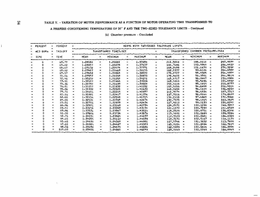
TABLE V. - VARIATION OF MOTOR PERFORMANCE AS A FUNCTION OF MOTOR OPERATING TIME TRANSFORMED To
A PREFIRE-CONDITIONING TEMPERATURE OF 20" F AND THE TWO-SIDED TOLERANCE LIMITS - Continued
(a) Chamber pressure - Concluded
- PERCENT - PERCENT - -~ - ~ ~ ~ ~ ~"" "~ ~
MEANS U I T H TWo-SIDED T0LESA:JCE L I M I T S - - UES BURN - TAILOFF - TRANSFORMED TIMES,SEC - TRANSFORME@ CHAMBER PRESSUREePSIA - - TIYE - TIYE - MEAN - MINIMUM - M P X I M U M - W A N - YINIMUM - MAXIMIJM
- - .....................................................
- - """"""""""""""""""""""""""""""""""""""""""""""-"""""" - ~"""""""""""""--""""""""""""""""-"""""""""""""""""""""""-"""""""""""" - 0 - 63.77 - 1.28582 - 1.20081 - 1.37084 - 2n1.5840 - 0 - 65.22 - 105.2110 - 297.9570 -
1.28857 - 1.20278 - 1.37437 - 0 - 66.67 - 194.7686 - 103.0940 -
1.29132 - 1.20474 - 1.37791 - 286.4432 - 0 - 68.12 - 1.29407 - 188.24A8 -
1.20669 - 1.38145 - 101.1679 - 275.329P - 0 - 69.57 - 1.29682 - 1.20864 1.38500 - 182.0337 - 99.4124 - 264.6550 - 0 - 71.01 - 176.2727 -
1.29957 - 98.0505 - 1.21058 - 1.38855 - 254.495" -
0 - 72.46 - 1.30233 - 170.6605 - 96.3591 - 1.21252 - 1.39211 - 244.9619 -
0 - 73.91 - 1.30507 - 1.21446 - 1.39568 - 165.6717 - 96.2447 - 235.09R6 - 0 - 75.36 - 1.30782 - 1.21639 - 1.39924 - 160.4844 - 95.5236 - 225.0452 - U - 76.81 - 155.5116 -
1.31057 - 95.1455 - 1.21832 - 215.8777 -
1.40282 - 0 - 78.26 - 1.31332 - 1.22024 - 150,5256 - 94.6498 - 206.4014 -
1.40639 - 0 - 79.71 - 1.31606 - 146.0654 -
1.22215 - 1.20997 - 96.1109 - 196.020n - 0 - 81.16 - 1.31881 - 141.91174 -
1.22407 - 1.41356 - 96.4834 - 187.3313 - 0 - 82.61 - 1.32156 - 137.9316 - 96.8144 -
1.22598 - 1.41715 - 179,OQRP - 0 - 84.06 - 1.32431 - 134.2118 - 97.4869 - 170.9366 - U
1.22788 - - 05.51 - 1.32706 - 1.42074 - 130.7535 - 98.1UQ5 - 163,3675 - 1.22978 - 1.42434 -
0 - 86.96 127.4212 -
1.32981 - 99.2133 - 1.23168 - 1.42794 - 155.6291 -
0 - P8.41 - 1.33256 - 1.23358 - 1.43154 - 124.2571 - 100.1290 - 148.3852 - 0 - 89.86 - 1.33531 - 121.1870 *
1.23547 - 1.43515 - 100.7230 - 141.6500 - 0 - 91.30 - 118.2528 -
1.33806 - 100.8751 - 1.23736 - 1.43876 -
0 - 92.75 - 1.34031 - 115.5991 - 1.23924 - 1.49237 - 101.2699 - 129.9284 -
0 - 94.20 - 1.34355 - 112.9523 - 101.2681 - 1.24112 - 1.49599 - 124.6365 -
0 - 95.05 - 1.34630 - 110.3170 - 1.24300 - 1.49961 - 102.5167 - 118.1174 -
0 - 97.10 - 1.34905 107.5746 -
1.24487 - 1.45323 - 101.3832 - 113.7699 - 0 - 98.55 - 1.35180 - 105.0054 - 101.2494 -
1.24674 - 108.7615 - 1 e45686 -
0 - 100.00 - 1.35955 - 1.24861 - 1 e46049 - 102.4855 - 100.5814 - 100.0049 - 100.0049 - 104.3896 -
. . . . . . . . . . . . . . . . . . . . . . . . . . . . . . . . . . . . . . . . . . . . . . . . . . . . . . . . . . . . . . . . . . . . . . . . . . . . .
- - - - - - - - - - - - - - - - - - - 135.631-16 - - - - - - - 1oo.nnw -

TABLE.V. - VARIATION OF MOTOR PERFORMANCE AS A FUNCTION OF MOTOR OPERATING TIME TRANSFORMED TO
A PREFIRE-CONDITIONING TEMPERATURE OF 20" F AND THE TWO-SIDED TOLERANCE LIMITS - Continued
(b) Thrust corrected to sea-level pressure altitude (PA)
. . . . . . . . . . . . . . . . . . . . . . . . . . . . . . . . . . . . . . . . . . . . . . . . . . . . . . . . . . . . . . . . . . . . . . . . . . . . . . . . . . . - PERCENT - PERCENT - MEANS WITH TWO-SIDED TOLERANCE L I M I T S - - WEB BURN - TAILOFF - TRANSFORMED TIMES - TRANSFORMED THRUST AT PA= 14.70 - - T I Y E - T I Y E - MEAN - MINIYUM - M A X I M U M - MEAN L
- - . . . . . . . . . . . . . . . . . . . . . . . . . . . . . . . . . . . . . . . . . . . . . . . . . . . . . . . . . . . . . . . . . . . - - . . . . . . . . . . . . . . . . . . . . . . . . . . . . . . . . . . . . . . . . . . . . . . . . . . . . . . . . . . . . . . . . . . . . . . . . - .oo - 0 - .78 - 0 - 1.56 - 0 - - 2.34 - 0 - - 3.12 - 0 - - 3.91 - 0 - - 4.69 0 - - 5.47 - 0 - - 6.25 - 0 - - 7.03 - 0 - - 7.81 - 0 - 8.59 - 0 - - 9.37 - 0 - - 10.16 - - - 10.94 - 0
- 11.72 - 0 0
12.50 - - - 13.28 - 0 0 - 14.06 - - - 14.84 - 0
- 15.62 - 0 0 - 16.41 - 0 - - 17.19 - - - 17.97 - 0 0
- 18.75 - 0 - - 19.53 - 0 - - 20.31 - - - 21.09 - 0 0 - 21.07 - 0 -
- -
- - - - - -
- 22.66 - 0 - - 23.44 - 0 - - 24.22 - - - 25.00 - 0
- 25.78 - 0
- 26.56 - 0 0 - 27.34 - -
28.12 - 0
- 28.91 - 0 0 - 29.69 - - - 30.47 - 0
- 31.25 - 0 0 - 32.03 - 0 - - 32.81 - - 0
- - - - - - -
w m
"""""""""""""""-
- .onooo - e00864 - -01728 - -02592 - ,03456 - -04320 - -05184 - .0604R - -06912 - -07776 - ,08640 - .09504 - 10368 - ,11232 - -12096 - -12960 - 13824 - 14688 - -15552 - -16416 - -17280 - .1 A144 - .I9008 - ,19872 - ,20736 - $21600 - e22464 - -23328 - ,24192 - e25056 - -25920 - -26784 - -27648 - ,28512
- e30240 -29376
- ,31104 - ,31968 - -32832 - -33696 - ,34560 - e35424 - 36288
-
""""
554.7539
9692.1997 5148.3537
14031.1770
21627.9663
26428.3047 24349.1724
27851.6973 28871.3391 29603.6497 30122.3662 30454,4233
30718,4448 30628.0525
30781.1016 30799.1714 30794.0~06
30648.1108 306?2.43@2
1801t4.9~02
30760.8499 30700.3264
30637.6697 30635.9929
30624.5146 30596.41R0 3 0 5 8 7 . m 3 30567.0854 30531.5771 30473.4204 30406.8477 50341.2742 30271.2639 30230.4053 30198.2031 30191.7659 30191.5127 30224.8423
30324.4390
30364.3618 30381.1667
30281.0923
30347.3477
,noon .noo i
.no00
.noon
9145.4687 1331.2754
15q29.4338
23730.5781 25R9R.1575
20797.7381l
28326.3325 27327.4302
28926.9468 29125.7405 29348.9543 29323.6399
29242.2791 29280.6165
29272.0386 29365.8230 29183.3486 29n90.5505
2 8 ~ ~ 2 . 5 h n 3
29060.9656 28941.7717
28736.5596 28699.9705 28682.1848
28553.6438 28610.2412
28546.1306 28606.7605
-28625.1423 28630.7056 28611.6182 28629.2620 28670.4016 28724.3030 28757.1709 28795.5515 28761.2068 28793.6133 28838.3994 .""""""
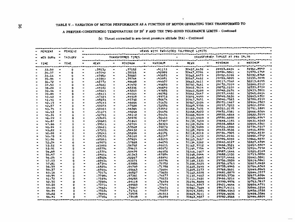
TABLE V. - VARIATION OF MOTOR PERFORMANCE AS A FUNCTION OF MOTOR OPERATING TIME TRANSFORMED TO
A PREFIRE-CONDITIONING TEMPERATURE OF 20" F AND THE TWO-SIDED TOLERANCE LIMITS - Continued
(b) Thrust corrected to sea-level pressure altitude (PA) - Continued
. . . . . . . . . . . . . . . . . . . . . . . . . . . . . . . . . . . . . . . . . . . . . . . . . . . . . . . . . . . . . . . . . . . . . . . . . . . . . . . . . . . . . . . . . . . . . . . . . . . . . - PERCENT - PERCENT - KEANS WITH TWO-SIDED TOLERANCE L I M I T S - - - . . . . . . . . . . . . . . . . . . . . . . . . . . . . . . . . . . . . . . . . . . . . . . . . . . . . . . . . . . . . . . . . . . . . . . . . . . . . . . . . . . - WE8 BURN - TAILOFF - TRANSFORMED TIMES - TRANS FOR ME^ THRUST AT PA= 19.70 - - - - . . . . . . . . . . . . . . . . . . . . . . . . . . . . . . . . . . . . . . . . . . . . . . . . . . . . . . . . . . . . . . . . . . . . . . . . . . . . - TIME - MEAN - MINIMUM - MAXIMUP - TIME - MINIMUM - HAXIMUM - MEAN - ""_"
33.59 34.37 35.16 35.94 36.72 37.50 38.28 39.06 39.84
41.41 40.62
9 2 - 1 9 42 97 43.75 44.53 45.31 4b.09 46.87 47.66 48.44 49 22 50.00 50 * 78 51.56 52 34 53-12 53.91 54 69 55.47 56.25 57.03 57 81 58.59 59.37 60.16 b0.94 61 -72 62.50 63.28 64.06 64.84 65 62 66.41
0 0 0 0 0 0 0 0 0 0 0 0 0 0 0 0 0 0 0 0 0 0 0 0 0 0 0 0 0 0 0 0 0 0 0 0 0 0 0 0 0 0 0
-37152 e38016 -38880 ,39744 ,40608 e41472 -42336 e43200 .44064 .44928 -45792 .46656 e47520 ,48384 e49248 e50112 ,50976 .51840 -52704 ,53568 54432 55296
,56160 e57024 .57888 ,58752 -59615 -60479 ,61303 e62207 -63071 .63935 ,64799 -65663 ,66527 ,67391 e68255 .69119 ,69983 -70847 ,71711 e72575 .73439
42069 043025 e43981 .44937 ,45893 46849
,47805 e48762 e49718 a50674 e51630 e52586 e53542 e54498 .55454 e56410 -57367 ,58323 e59279 -60235 -61191 e62147 ,63103 e64059 e65015 e65972 e66928 e67884 -68840 069796 e70752 e71708 e72664 ,73620 .74577 .75533
76989 ,77445 7840 1
.79357 e80313 e81269
30437.6438 - 30487.0796 - 30542.6973 - 30597.6462 - 30665.6611 - 30730.9661 - 30R02.9414 - 30840.8289 - 30851.5447 - 30871.4990 - 30917.9851 - 31029,9756 - 3 1 0 ~ 0 . 7 0 3 1 - 31058,8223 - 31088.9009 - 31123.6919 - 31128.9604 - 31139.7659 - 31130.5999 -
30987.2026 -
31125.3909 - 31118.8018 - 31116.1450 - 31123.3667 - 31134,1262 - 31194.7759 - 31198.0044 - 31188.8865 - 31188.1331 - 31206.8625 - 31220,2646 - 31209.2273 - 31162.6228 - 31130.4912 - 31111,2930 - 31076.8806 - 31040.4707 - 30980.7664 - 30919.5391 - 30889.9011 - 30863.4587 -
31162.9712 - 31206.1907 -

TABLE V. - VARIATION OF MOTOR PERFORMANCE AS A FUNCTION OF MOTOR OPERATING TIME TRANSFORMED TO
A PREFIRE-CONDITIONING TEMPERATURE OF 20" F AND THE TWO-SIDED TOLERANCE LIMITS - Continued
(b) Thrust corrected to sea-level pressure altitude (PA) - Continued
""""-"-""""""""""--"""""""""""""""-"""""""""""""""""""~"""""""""""""~ - PERCENT - PERCENT - MEANS WITH TWO-SIDED TOLERANCE L I M I T S - - - """"~""""""""""""""""""-"""""""""""""""""""""""-"""""" - dEB BURN - TAILOFF - TRANSFORMED TIMES - TRANSFORME@ THQUST AT PA= 14.70 - - - """""""""""--""""""-""""-"""""""""""""""""""""""-"""""" - TIYE - TIME - MEAN - MIYIVUM - M A X I M U M - MEAN - LrINIMUY - M A X I M l l Y - ................................................................... - 67.19 - 0 - b7.97 0
,82225 - 30850,4297 - 29232.7344 , - 32468.125fl - - 68.75 - 0 ,80084 - - b9.53
,76031 - .a4138 - 307~8.0398 - 2 9 1 ~ 0 . 9 6 6 ~ - 32485.11m - 0 ,80995 - - 70.51 - -76895 - 0 .81905 - - 71.09 - 0 e82815 - - 71.87 - .7R623 - 0
,87006 - 30603.58C6 - 29124.7217 - 32082.4556 - ,83725 - ,79487 - .a7962 - 3 o 5 3 0 . 1 ~ ~ 1 - 29092.3259 - 3 1 9 6 8 . 0 3 ~ - - 72.66 - 0 - -84635 - - 13.44 - 0 -
,88918 - 30465.8164 - 29'343.4121 - ' 31888.2207 - e85545 - - 74.22 - ,81215 -
0 .86455 - - 75.00 - -87079 - 0
-90830 - 30372.7935 - 20a98.3391 - 31847.247n - -87365 - -82943 - e91786 - 30325.9717 - 28902.3516 - 31749.5937 -
- 76.56 - 0 - 77.34 - -891Pg - -84671 - e93699 - 30222.5627 - 28909.5830 - 31640,5425 - 0 -90095 - ,85535 - - 78.12 - -94655 - 30191,8318 - 28757.3247 - 31626.318R - 0 - 78.91 - -91005 - 0
-86399 - ,95611 - 30200.2017 - 29797.5479 - 31602.8555 - - 79.69 - e91915 -
0 ,87263 - -96567 - 30193.7251 - 28946.6116 - 31540.0386~ -
*9?M25 - - 80.47 - .R0127 - 0
-97523 - 30172.8320 - 28R01.1711 - 31544.4929 - .93?35 - .I38991 - - 81.25 - e98479 - 30129.0327 - 28755.7056 - 31502.3590 -
0 - 82.03 - e94645 - 0
-89855 - .99435 - 30096.13?8 - 28747.4236 - 31444.842n - - t12.81 - .95555 - -90719 - 1.00391 - 30073.1R53 - 28767.6294 - 31378.7413 - - t33.59 - 0 .97375 - ,92447 - - 84.37 - 0
1.02304 - 30002.1130 - 28670.6294 - 31333.5967 - - 85.16 - 0
,98285 - . 9 m 1 - 1.03260 - 29960,3904 - 28579.7078 - 3 1 3 ~ 1 . n ~ 9 1 - ,99196 - -94175 - 1.04216 - 29932.5813 - 28472.9741 - 31592.1885 - - 85.94 - 0 - 86.72 - 0
1.00106. - e95039 - 1.05172 - 29918,8188 - 28456.5193 - 31401.1144 - 1.0101rj - - 87.50 - 0
-95903 - 1.06128 - 29919.6719 28355.0908 - 31481.252s. - - 88.28 - 1.0192<, -
0 1.0283~, - ,97631 - 1.08040 - 29923.4365 - 28218.9146 - 31627.9585 - - 89.06 - 0 - 1.03746 - - 89.84 - 0 1.04656 - - 90.62 - 0 - 91.41 - 0 1.05566 - 1.00223 - 1.10909 - 29832.6653 - 28316.5432 - 31448.7872 -
- 92.19 - - 1.06476 - 1.01087 - 1.11865 - 29853.3630 - 28136.7705 - 31569.9556 - 0 - 92.97 - 0
1.07386 - 1.01951 - 1.12821 - 29888.69CO - 28030.8547 - 31746.5413 - - 95.75 - 1.08296 - 1.02815 - 1.13777 - 29895,8608 - 27946.1982 - 31R45.5234 - - 9Y.53 - - 95.31 - 0 - 1.11026 - 1.05407 - 1.16645 - 29815.9790 - ' 27R87.9568 - 31744.001P - - 96.09 - 0 - 9b.87 - - 1.11936 - 1.06271 - 1.17601 - 29777,5916 - 27799.9087 - 31755.2744 - - 97.66
0 0 - 1.13756 - 1.07999 - 1.19514 - 29628.2266 - 27419.4819 - 31836.9712 . - 1.12846 - 1.07135 - 1.18558 - 29725.1157 - 27671.7461 - 31778.4854 -
- 99.22 - 0 - 1.15576 - 1.09727 - 1.21426 - 28786.1938 - 25A88.3892 - 31683.99R5 - --"""-"-------"""--"""--""""~"""-"""""""""""""""""~"""""""""""""""""""""""
- a78264 - -74303 - -79174 - ,75167 - - - ,83182 - 30827.3728 - 29156.7249 - 32499.n?n~ -
.a5094 - 30741.8774 - 29n67.43~n - 32416.3169 - .77759 - .86050 - 3 0 6 ~ 0 . 8 ~ 3 1 - 29n98.9319 - 33262.~342 - .an351 -
- - - - - .a9874 - 30409.7517 - 28994.2830 - 3187s.lRn4 -
- 75.78 - 0 -88275 ,83807 - ,92743 - 30269.3164 - 28R61.4397 - 31677.1931 - - - - - - - - - -
0 - ,96465 - -91583 - 1.01348 - 30044.6577 - 28749.382R - 31339.9326 - - - - - - - - .96767 - 1.07084 - 29930.1042 - 28242.396n - 31617.8125 - . 9 w 9 5 - 1.08996 - 29887.0417 - 28240.542s - 31533.5410 - .99359 - 1.09953 - 29853.2688 - 28242.3276 - 3146~.21nn - - -
- - 0 - 1.09206 - 1.03679 - 1.14733 - 29882.2026 - 27913.4619 - 31850.9434 - 0 - 1.10116 - 1 . 0 ~ 5 4 3 - 1.15689 - 29850.2043 - 27912.6240 - 3178717847 -
- 98.44 - 0 - 1.14666 - 1.08863 - 1.20470 - 29368.6846 - 26889.0061 - 31848.363p - - 100.00 - 0 - 1.16487 - 1.10591 - 1.22382 - 27729.8345 - 24361.7292 - 31097.9397 -
0 4
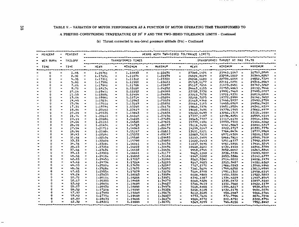
W 03 TABLE V. - VARIATION OF MOTOR PERFORMANCE AS A FUNCTION OF MOTOR OPERATING TIME TRANSFORMED TO
A PREFIRE-CONDITIONING TEMPERATURE OF 20" F AND THE TWO-SIDED TOLERANCE LIMITS - Continued
(b) Thrust corrected to sea-level pressure altitude (PA) - Continued
""""""""""""~"""~"""""~""""""""~"""""""""""""~""""""""""""""---""~"-""" - PEXCENT - PERCENT - MEANS UITH TWO-SIDED TOLERANCE L I M I T S - - - ""~"""""~""""""""""""""""""""""""~""""""""""""--""""""" - UEB BURN - TAILOFF - TRANSFORMED TIMES - -1RANSFORMEC THPUST AT PA= 14.70 - - - "~""~""_"""""""""""~"""""""""""""~""""""""""""""""""""" - TIME - TIME MEAN - M I N I Y U M - MAXIMUM - MEbN - MINIMIJM - MAXIMUM """"""""""""""""~""""""""""""""""""""""""~""""""""""""""""-"~""""""~ - - - 0 - 1.45 - 1.16761 - 1.10833 - 1.22690 - 27300.1916 - 23R43.1047 - 30757.2PO5 -
0 - 2.90 - 1.17036 - 1.11074 - 1.22999 - 26824.0029 - 23298.1802 - 30349.8257 - 0 - 4.35 - 1.17311 - 1.11312 - 1.23310 - 26296.1689 - 22739.6050 - 29852.7320 - 0 - 7.25 - 1.17861 - 1.11786 - 1.23937 - 25107.7856 - 21473.2451 - 28742.3262 - 0 - 8.70 - l.lUl36 - 1.12020 - 1.24252 - 24443.1155 - 20753.4863 - 28132.744h - 0 - 10.14 - 1.18rCl.l - 1.12252 - 0
1.24569 - 23738.3738 - 19991.7468 - 27485.0007 - - 11.59 - 1.18686 - 0 - 13.04 - 1.124R4 - 1.24888 - 23010.7570 - 19201.9330 - 26R19.6826 -
1.18961 - 0 - 14.49 - 1.19236 - 1.12942 - 1.12714 - 1.25208 - 22256.3225 - 18372.299R - 26140.3453 - 0
1.25529 - 21469.4348 - 17446.5937 - 25492.2759 - - 15.94 - 0 - 17.39 - 0 - 18.84 - 1.19785 - 1.13395 - 1.26176 - 19846.3376 15451.2524 - 24241.lt27" -
1.20060 - 1.13619 - 0
1.26501 - 19020.34A6 - 14379.1995 - 23661.497P - - 20.29 - 1.20335 - 1.13843 - 0
- - 0 - 5 .80 - 1.17586 - 1.11550 - 1.25623 - 25728.6177 - 22141.0291 - 29316.2065 - - - - - - - - - 1.19510 - 1.13169 - 1.25852 - 206hl.1165 - 16465.6909 - 24856.542n - 1.26828 - 18193,6499 - 13266.1318 - 23121.168n - - 21.74 - 1.20610 - 1.14065 - 1.27156 - 17377.1187 - 12199.8254 - 22559.4119 -
0 - 23.19 - 1.20885 - 0 - 24.64 - 1.2116n - 1.14505 - 1.27815 - 15779.19~1 - lon93.7900 - 21464.6062 - 1.14285 - 1.27485 - 16565.7727 - 11117.4170 - 22014.12~4 - 0 - 26.09 - 0 - 27.54 - 1.21435 - 1.14723 - 1.281'47 - 15016.0491 - 9141.5663 - 20890.5317 -
1.21710 - 0 - 28.99 - 1.21985 - 1.15157 - 1.28813 - 13571.0221 - 1.14940 .- 1.28479 - 14279.0247 - 8222.2717 - 20335.7776 -
- 30.43 - 1.22260 - 1.15372 - 1.29147 - 12889.7819 - 7764.0474 - 19777.996A - 0 - 31.88 - 1.22534 - 1.15586 - 1.29483 - 12233.2R59 - 5R66.7810 - lR599.790P - 6571.4308 - 19208.132~ - 0 - 33.33 - 1.22~09 - 1.15799 - 1.29820 - 11622.0443 - 5251.9377 - 17992.6509 - 0 - 34.78 - 1.23080 - 1.16011 - 1.30158 - 11037.9036 - 0 - 37.68 - 1.23634 - 1.16432 - 1.30836 - 9958.2744 - 3652.6642 - 16263.8846 - 0 - 39.13 - 1.23909 - 1.16641 - 1.31177 - 9465.1268 - 3336.3336 - 15693.9200 - 0 - 40.58 - 1.24184 - 1.16850 - 1.31518 - '8997.0082 - 2853.5386 - 15140.6777 - 0 - 43.48 - 1.24734 - 1.17264 - 1.32203 - 8147,9925 - 0 - 44.93 - 1.25009 - 1.17470 - 1.32547 - 7757.2770 - 0 - 46.38 - 1.25284 - 1.17675 - 1.32892 - . 73A1.5624 - 1966.0593 - 13508.49~6 - 0 - 47.83 - 1.25558 - 1.17879 - 1.33238 - 7024.8708 - 0 - 49.28 - 1.25033 - 1.18083 - 1.33584 - 66R6.4565 - 0 - 50.72 - 1.26106 - 1.18286 - 1.33931 - 6371.1387 - 0 - 52.17 - 1.26383 - 1.18488 - 1.34279 - 6066.4326 - 0 - 53.62 - 1.26658 - 1.18689 - 1.34627 - 5786.9419 - 1151.7660 - 10422.117P - 1235.0472 - 10897,8180 - 0 - 57.97 - 1.27483 - 1.19289 - 1.35676 - 5012.2625 - 1n32.2178 - 9481.0071 - 0 - 59.42 - 1.27756 - 1.19488 1.36027 - 4773.7626 - 0 - 60.87 - 1.28033 - 1.19686 - 0 - 62.32 - 1.28308 - 1.19884 - 1.36731 - 4349.8299 -
- - - - - - - - - 0 - - - - 0 - 36.23 - 1.23359 - 1.16222 - 1.30496 - 104~8.2601 - 466lr4856 - 17414.3215 - 4130.1418 - 16846.3784 - - - - - 0 - 42.03 - 1.24453 - 1.17057 - 1.31860 - 8560.53ltl - - 2514.9202 - 14606.14.79 - 2215.3487 - 14080.6562 - 1749.6258 - 13013.4989 - 1591.1302 - 12458.6115 - 1450.3326 - 11922.5803 - 1334.4229 - 11407.8545 -
- - - - - - - - 0 - 55.07 - 0 - 56.52 - - 1.26933 - 1.18890 - 1,34976 - 5516.6368 -
1.27208 - 1.19090 - 1.35326 - 5256.6125 - 1094.6217 - 9938.651q - 958.2487 - 9066.2764 - 872-7996 - 8674.7256 -
1.36379 - 4554.8772 - 800.8790 - 8308.8754 - 7Y6.8156 - 7952.8242 -
- - - - . . . . . . . . . . . . . . . . . . . . . . . . . . . . . . . . . . . . . . . . . . . . . . . . . . . . . . . . . . . . . . . . . . . . . . . . . . . . . . . . . . . . . . .

TABLE V. - VARIATION OF MOTOR PERFORMANCE AS A FUNCTION OF MOTOR OPERATING TIME TRANSFORMED TO
A PREFIRE-CONDITIONING TEMPERATURE OF 20" F AND THE TWO-SIDED TOLERANCE LIMITS - Concluded
(b) Thrust corrected to sea-level pressure altitude (PA) - Concluded
"""""""-"-""""""""""""""""""""""-""""""~"""""""""""""""""""""""-"""" - - ..................................................... - lJEB BURN - TAILOFF - TRANSFORMED TIMES - TRANSFORMED THRUST AT PA= 14.70 - - - """""""""""""""""""-"-""""""""""""""""~""""""""""""""~~ """"""-~-""""~"~"""""""-""""""""""-""""""""""""""""""""""""""""""--"~"~
- PERCENT - P ~ R C E N T - YEANS WITH TWO-SIDED T.0LERANCE L I M I T S -
- T I Y E - TIME - dEAN - MINIMUM - MAXIMUM - MEAN - M I V I M U Y - MAXIMlJP - 0 - 63.77 - 1.28582 - 1.200A1 - 1.37084 - 4148.9938 - 683.5098 - 7614.4777 - 0 - 65.22 - 1.28857 - 1.20278 - 1.37437 - 3959.1447 - 609.5A56 - 7309.7039 - 0 - 66.67 - 0 - b8.12 - 1.29407 - 1.20669 - 1.38165 - 3614.4293 - 1.29132 - 1.2n474 - 1.37791 - 3781.9048 - 518.6768 - 7045.1377 -
~ 4 3 . ~ 1 5 - 67~5.017n - - 0 - 69.57 - - 0 - 71.01 - 1.29957 - 1.21058 - 1.38855 - 3321.1R56 - 0 - 72.46 - 1.30232 - 1.21252 - 1.39211 - 3185.9037 - 341.7373 - 6300.6339 - 0 - 73.91 - 1.30507 - 1.21446 - 1.39568 - 3057.9306 - 0 - 75.36 - 1.30782 - 1.21639 - 1.39924 - 2933,49AA - 708.9398 - 5559.0579 -
- 0 - 78.26 - 1.31332 - 1.22024 - 1.40639 - 2715.3181 - 339.1031 - so91.5mn - 0 - 82.61 - 1.32156, - 1.22598 - 1.41715 - 2518.3867 - 337.1912 - 4499.5829 -
- - - - 1.29682 - 1.20864 - 1.38500 - 3467.04l73 - 378.5117 - 6555.5689 -
326.0447 - 6095.7626 - 308.7873 - 5807.0739 - - - - - 0 - 76.81 - 1.31057 - 1.21832 - 1.40282 - 2818.2262 - 512.715n - 5323.7773 -
0 - 79.71 - 0
1.31606, - 1.22215 - 1.40997 - 2608.9593 - - 81.16 - 1.318A1 - 1.22407 - 1.41356 - 2508.1811 - 329.893A - 4888.0247 - 320.0096 - 4696.3525 -
0 - 84.06 - 1.32431 - 1.22788 - 1.42074 - 2336.1451 - 372.5615 - 4299.72RA - 0
1.42434 - 2255.8RR9 - - 86.96 - 1.32981 - 1.23168 - 1.42794 - 2174,4R@5 - 377.5249 - 4134.252A - 382.8271 - 3966.1339 -
- - - - - 0 - 85.51 - 1.32706 - 1.22978 - - - 0 - 98.41 - 1.33256 - 1.23358 - 1.43154 - 2095.9744 - 0 - 89.86 - 1.33531 - 1.23547 - 1.43515 - 2020.9644 - 375.6129 - 3816.336n -
369.321n - 3672.607~ - - 0 - 92.75 - 1.34081 - 1.23924 - 1.44237 - 1893.3728 - - 0 - 94.20 - 1.34355 - 1.24112 - 1.44599 - 1833.9030 -
0 - 95.65 - 1.34630 - 1.24300 - 1.44961 - 1772,4390 - 0 - 97.10 - 1034905 - 1.24487 - 1.45323 - 1718.6741 - 0 - 98.55 - 1.35180 - 1.24674 - 1.45686 - 1663.0090 - 0 - 100.00 - 1.35455 - 1.24861 - 1.46049 - 1613.7ySO - . 398.5517 - 2828.93Ru - 382.6674 - 2 9 ~ 3 . 3 ~ 0 7 -
- - 0 - 91.30 - 1.33806 - 1.23736 - 1.43876 - 1953,0846 - 362.2395 - 3543.929fi - 355.5204 - 3431.2252 - 350.8985 - 3316.907s - 366.7974 - 3182.0807 - 369.9616 - 3067.3865 - - - - - -""""""-----""""""""""""""""""""""""""""""""""""""""""""""""""""""""~
cn W
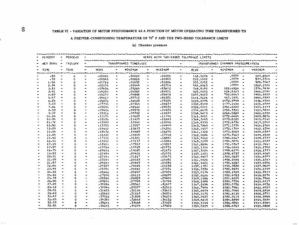
rp 0 TABLE VI. - VARIATION OF MOTOR PERFORMANCE AS A FUNCTION OF MOTOR OPERATING TIME TRANSFORMED TO
A PREFIRE-CONDITIONING TEMPERATURE OF '70' F AND THE TWO-SIDED TOLERANCE LIMITS
(a) Chamber pressure
.................................................................. - PEXCENT - PERCEIU - V E I N S WITH TWO-SIDED TOLERANCE L I M I T S - - WE3 BUHII - TAILOFF - TRANSFORMED TIHES,SEC - TRANSFORMEP CHPMRES PQESSURE*PSIh - - - .....................................................
- - ...................................................... - T I Y E - TIME - YEAPI - MINIUUM - M A X I M U M - - Y I V I M U Y - U A X I Y l N - .00
1.56 .78
2.34 5.12 5 - 9 1 4.69 5.47 6.25 7.03 7.81 8.59
10.16 9.37
1U.94 11.72 12.50 13.28 14.06 14.84 15.62 16.41 17.19 17.97 18.75
20.31 19.53
21.09 21.87 22.66 23.44 24.22 25.00 25.78 26.56 27.34 28.12 28.91 29.69 30.47 31.25 32.03 32.81
0 0 0 0 0 0 0 0 0 0 0
0 0
0 0 0 0 0 0 0 0 0 0 0 0 0 0 0 0 0 0 0 0 0 0 0 0 0 0 0 0 0 0
.00000
.OO86O -01719 -02579
03438 - 0 4 2 9 ~ ,05157 -06U17
06876 .07736
08595 .09455 -10315 - 1 1 1 7 ~ .12us4
12693 .13?53 -14617
15472 ,16331 -171Y1 .1805n
1891 0 19769
-20629 .2148Q .22341\ , 2 3 2 0 ~ ,24067 -24927 -25786 -26646 -27505 -28365 ,29224 .30084 e30944 -31803 -32663 -33522 -34382
35241 ,36101
.ooooo
.00816 - 0 1632 .02440 -03264 .O4ORO ,04896 .OS712 -06528 .07344 .08160 .OR976 .09792 . lo609 .11425 ,12241 -13057 .13873 ,14689 -15505 -16321 ,17137 .17953 . 1 R769 ,19585 .20401 -21217 -22033 ,22849
23665 .24481 -25297 -26113 ,26929 .27745 ,28561 ,29377 -30194
.31826 -32642 .33458 -34274
,31010
.ooooo -00903 -01806 -02709 -03612 e04515 ,05418 -06321 e07224 -09127 -09030 .09933 e10837 e l1740
12643 13546
.14449 15352 16255
-17158 . l 8 0 6 l
18964 19867
-20770 -21673
e23479 ,22576
,24382 ,25285 ,26188 ,27091 ,27994 e28897 -29800 -30704 -31607 -32510 -33413 ,34316 ,35219 -36122 ,37025 37928
2?0.1002 - 102.3278 - 373.0252 - 554.6963 - 748.81PO - 925.0452 -
1077.40?3 - 1 1 ~ 1 . 0 6 2 6 - 1255.2375 - 1300.80no - 1328.uon1 - 1341.3n81 - 1354.6575 - 1338.4R13 - 1344.31185 - 1344.8793 - 1343.7869 - 1342.1557 - 1 3 ~ 1 . 1 3 2 8 - 1342.09R6 - 1344.9060 - 1348.21n5 - 1351.8p94 - 1355.1700 - 1357.3024 - 1359.1901 - 1361.4526 - 1361.4421 - 1359.1781 - 1356.3339 - 1353.0174 - 1350.6526 - 1349.1986 - 1348.19P6 - 1347.2496 - 1346.79R4 - 1345.6979 - 1345.1435 - 1345.4537 - 1349.6215 - 1352.4148 - 1354.5825 -
1360.8507 -
.noon -
.onno -
.noon -
.noon - 122.6924 - U04.03?3 - 700.6441 - 017.1871 -
1n73.9790 - 1241.hH09 - 11 77.1400 - 175R.7320 - 1268.5289 - 1272.6489 - 1273.6028 - 1772.9736 - 1271.3774 - 1772.1759 - 1373.5269 - 1275.7463 - 1280.6543 - 1?84.9R74 - 1 m . n ~ + 7 - 1396.06lR - 1798.6275 - 1300.0637 - 1298.9737 - 1798.2285 - 1795.4287 - 1290.3938 - 1385.987r) - 1?83.1929 - 1782.4783 - 1281.6005 - 1280.7754 - 1280.0756 - 1281.7991 - 1281.7040 - 1?81.6139 - 1282.3119 - 1284.6899 - 1286.9991 - 1288.6763 -
TABLE VI. - VARIATION OF MOTOR PERFORMANCE AS A FUNCTION OF MOTOR OPERATING TIME TRANSFORMED TO
A PREFIRE-CONDITIONING TEMPERATURE OF 70" F AND THE TWO-SIDED TOLERANCE LIMITS - Continued
(a) Chamber pressure - Continued
.................................................................. - PERCENT - PERCEdT - MEANS WITH TWO-SIDED TOLERAtIcE L I M I T S
- WE8 BURN - TAILOFF - TRANSFORMED TIMES,SEC - TRANSFORMEn CHAYBFR P ~ F S S U ~ E V P S I A - - T I Y E - TIYE - MEAN - MINIMUM - M A X I M U M - MEAN - MINIMUM - M A X I M I I M - - - ......................................................
- - .......................................................
-"""""""""""""""""""""""""""""""""""""""""""""""""""""""""""""~"""~ 33.59 34.37 35.16
36 72 35.94
37.50 38.28 39.06 39.84
41.41 40.62
42.97 42.19
43.75 44.53 45.51 46.09 46.87 47.66 48.44 49.22 50.UU 50 78
52.34 51.56
53.12 53.91 54 69 55.47 S6 -25 57.03 57.81 58.59 59.37 60.16 60.94 61.72 62.50 63.28 64.06 64.84 65.62 66-41
0
0 0
0 0
0 0 0 0 0 0 0 0 0 0 0 0 0 0 0 0 0 0
0 0
0 0
0 0
0 0 0 0
0 0
0 0 0 0 0 0 0 0
.35090 -35906 36722
.38354
.37538
-39986 .39170
.4n802
.4161e -42434 ,43250
.44882 ,44066
-45698 .46514
-48146 -48962 .4977R .50595 .51411 -52227 .53043 .53859 -54675 -55491 ,56307 -57123 ,57939
-59571 ,58755
-60387
.47330
,61203 e62019 ,62835 -63651 -64467 -65283 ,66099 e66915 e67731 ,68547 ,69563
38831 .39734 ,40637 "41540 -42943 43346
"+4249 ,45152 -46055 46958
-27861 ,48764 ,49667 e50571 -51474
52377 -53280 -54183
.5S989 -55086
,56892 .57795 -58698 -59601 ,60504 -61407 -62310 ,63213 ,64116 e65019 65922
.6682> e67728 ,68631 ,69534 e70438 .713@1 -72244 e73147 ,74050 ,74955
76759 -75856
1354.4272 - 1352.9169 - 1352.6316 - 1352.90i)b - 1358.6297 - 1355.9377 - 1363.2802 .. 1367.7746 - 1371.86R7 - 1373.3512 - 1374.9807 - 1377.0241 - 1377.5431 - 1377.2190 - 1377.9?63 - 1379.8391 - 13p3.0l(l2 - 1387.0111 - 1391.5359 - 1395.8779 - 14170.2332 - 1403,0473 - 1404.6977 -
1353,8014 -
1375.9500 -
1404.5834 - 1404,3999 - 1404.5057 c 1405.7907 - 1406.03174 - 1405.R661 - 1404,5714 - 1403.1511 - 1902.9550 - 1903.01'12 - 14n1.6688 - 1399.4053 - 1396.9731 - 1396.0577 - 1397.0319 - 1398.9925 - 1398.8250 - 1397.1182 -
128a.snso - 1 7 8 9 . n ~ 1 7 - 1?89.2123 - 1289.6125 - 1788 3324 - 1289.9865 - 1791.91R9 - 1796.5064 - 1301.2298 - 1309.8661 - 1306.42G4 - 1312.4686 - 1312.0143 - 1713.0194 - 1311.52R6 - 1309.9300 - 1310.2459 - 1312.5746 - 1316.4085 - 1318.7RlR - 1322.4993 - 1323.1244 - 1324.0782 - 1324.1167 - 1325.1510 - 1526.4122 - 1326.4796 - 1326.4R89 - 1327eA714 - 1327.7956 - 1327.8370 - 1326.9635 - 1325.9452 - 1325.5071 - 1326.3297 - ,
1322.8260 - 13?3.7951 - 1322.5132 . - 1322.7709 - 1321.7269 - 1319.0883 - 1314.8428 - 1309.0937 -
TABLE VI. - VARIATION OF MOTOR PERFORMANCE AS A FUNCTION OF MOTOR OPERATING TIME TRANSFORMED TO
A PREFIRE-CONDITIONING TEMPERATURE OF 70" F AND THE TWO-SIDED TOLERANCE LIMITS - Continued
(a) Chamber pressure - Continued
""""~"""""""""""""""""""""""""""""""""~""""""~""""""""""""""""""""" - PERCENT - PERCENT - WEANS WITH TWO-SIDED TOLERANCE LIUITS - - WE3 BURN - TAILOFF - TRANSFORMED TIMES,SEC - TRANSFORMED CH~MBER PRFSSUREIPSIA - - T I Y E - TIME - MEAN - MINI 'AUM - M A X I M U M - MEAN - MIbJIMUM - KAXIMUM
- - .......................................................
- ...................................................... - """"""""""~"""""""""""~"""""""""""""""""""""""""""""""-""~"""""""""~ 67.19 67.97 68.75
70.31
71.87 71.09
72.66 73.44 74.22 75-00 75.78 76.56 77.54 78.12 78.91 79.69
91.25 32.03 62.81 83-55) M4.37 M5.16 85.94 36.72 57-50 83-28 89.06
69.53
80 e47
09.80 90.62 91.41 92-15) 92.97 93.75 94.53 95.31 96.09 96.87 97.66 98.44 99.22
100.00
0 0 0 0 0 0 0 0 Q 0 0 0 0 0 0 0 0 0 0 0 0 0 0 0 0 0 0 0 0 0 0 0 0
0 0
0 0 0 0 0 0 0 0
e70180 .7099b ,71812 .7262R ,73944
.75076 -74260
-75892 -76708 -77524 .'I8340 ,79156 79972
,80788 .81604
-83236 ,84052 .A4868 .85684 .a6500 .a7316 -89132
R9764
-91397 -92213 ,93029 .93845 ,94661 .95477 96293
-97109 .97925 -98741
1 00373 ,99557
1.01189 1.02005 1.02821 1 e03637 1.04453
. ~ 2 4 2 n
e88940
,90581
1394.2316 - 1391.9155 - 1389.9899 - 13A8.1328 - 1385.4368 - 13R2.41AO - 1378.8213 - 1375.86P9 - 1373.0275 - 1370.2698 - 1368.0463 - 1365.7366 - 1363.7230 - 1360.8661 - 1357.7801 - 1354,9932 - 1353.0300 - 1352.6273 - 131t9.4854 - 1349.43R6 - 1350.6629 - 1349.78u8 - 1349.1147 - 1349.2118 - 1350.5958 - 1354.3829 - 1352.5815 - 1355.1887 - 1355.001tO - 1354.3009 - 1351.9687 - 1350.3420 - 1349.3449 - 1351.3294 - 1349.5828 - 1353.1933 - 1354.0519 - 1353.0242 - 1346.4695 - 1326.4564 - 1284.8251 -
1351.2900 -
1 3 ~ 0 . 2 7 0 9 -
1 ~ 0 5 . 1 6 3 6 - 1502.4268 - 1301.5464 - \301.2802 - 1300.1905 - 1?98.A406 - 1295.7225 - 1793.4528 - 1291.1286 - 1789.9393 - 1289.2526 - 1288.46R6 - 1288.no81 - 1288.4747 - 1287.5122 - 1285.3689 - 1282.7556 - 1779.8176 - 1278.3353 - 1277.15n2 - [email protected] - 1277.7221 - 1277.3364 - 1276,9299 - 1375.7730 - 1277.7604 - 1?79.4234 - 1379.7017 - 1770.8AR7 - 1 m . 9 6 5 1 - 1276.9681 - 1276.0997 - 1273.0697 - 1264.1009 - 1768.6179 - 1261.5753 - 1261.1910 - 1261.0207 - 1256,4607 - 1248.6291 - 1233.7079 - 1206.5371 - 1152.9142 -
.
TABLE VI. - VARIATION OF MOTOR PERFORMANCE AS A FUNCTION OF MOTOR OPERATING TIME TRANSFORMED TO
A PREFIRE-CONDITIONING TEMPERATURE OF 70" F AND THE TWO-SIDED TOLERANCE LIMITS - Continued
(a) Chamber pressure - Continued
""""""""""""""""~""~"""""""""""""""""""""""""~-""""""-"--""""--"""--""-- - PERCENT - PERCENT - MEANS WITH TWO-SIDED TOLERANCE LIMITS - - - """""""""""""""""""-"""-"""""""""""""""-"--""""--"""--""-- - WEB 6URN - TAILOFF - TKANSFORMED T I M E S ~ S E C - TRANSFORMED CHAMRER PRESSUREtPSIA - - - """""""""""""""""""""""""""""""""""""""-""""""""""""" - T I Y E - T I M E - MEAN - MINIWUM - MAXIYUM - YEAN - MINIMUM - MAXIMIJM - 0 - 1.45 - 1.10296 - 1.04696 - 1.15896 - 1265.7986 - 1131.2732 - 1400.3239 - 0 - 2-90 - 1.10571 - 1.04937 - 1.16205 - 1243.1051 - 1106.5804 - 1379.629A - 0 - 4.35 - 1.10806 - 1,05177 - 1.16514 - 1217.7949 - ln79.2702 - 1356.3197 - 0 - 5.80 - 1.11121 - 1.05415 - 1.16826 - ll89.42(r9 - 1049.6035 - 1329.238? - - 7.25 - 1.11395 - 1.05652 - 1.17139 - 1157,4960 - 1n15.9215 - 1299.0705 - 0 - 8.70 - 1.1167n - 1.05887 - 1.17453 - 1122.7321 - 0 - 10.14 - 1.1194s - 1.06121 - 1.17768 - 10~5.9n39 - 0 - 11.59 - 1.12220 - 1.06354 - 1.18085 - 1047.3192 - ~93.4024 - 1201.23hn - 937.nn83 - 1234.7995 - 0 - 13.04 - 1.12494 - 1.06585 - 1.18404 - 1007.3941 - 0 - 14.49 - 1.12769 - 1.06815 - 1.18724 - R49.0187 -
965.7292 - 1165.7696 - R00.890R - 1130.5677 -
0 - 15.94 - 1.13044 - 1.07043 - 1.19045 - 0 17.39 - 1.1331~1 - 1.07271 - 1.19367 - 923.4629 - 750.9469 - 1095.9789 - 0 - 18.84 - 1.13594 - 1.07497 - 1.19690 - 8R1.8421 - 701.8965 - 1061.7R76 - 0 - 20.29 - 1.1386s - 1.07721 - 1.20015 - 839.89PO - 653.1003 - 1026.69S9 -
798.2981 - 0 - 23.19 - 1.1441R - 1.08167 - 1.20668 - 758.2781 - 557.7686 - 950.7876 - 0 - 24.64 - 1.14693 - 1.08389 - 1.20997 - 720.1224 - 513.6292 - 926.6155 - 0 - 26.09 - 1.14967 - l.OR609 - 1.21326 - 683.3024 -
647.9922 - 472.2107 - 894.3941 - 0 - 27.54 - 1.15242 - 1.08828 - 1.21656 - 433.3092 - 862.6752 -
- 0 - 28.99 - 1.15517 - 1.09046 1.21988 - 614.41F7 - 397.2699 - 583.1350 - 831 -5674 -
0 - 30.43 - 1.15792 - 1.09263 - 1.22320 - 364.3954 - 801.8746 - 0 - 31.88 - 1.16066 - 1.09479 - 1.22654 - 553.5779 - 333.9576 - 773.3982 - 0 - 33.33 - 525.9922 -
1.16341 1.09694 - 1.22988 - 307.0436 - 744.94119 - 0 - 34.78 - 1.16616 - 1.09909 - 1.23323 - 499.8270 - 282.0877 - 717.5663 - 0
475.5800 - - 36.23 - 1.16891 - 1.10122 - 1,23660 - 259.9291 - 452.65R4 - 691.2300 -
0 - 37.68 - 1.17166 - 1.10334 - 1.23997 - 240.1099 - 665.207n - 431.5551 -
0 - 39.!3 - 1.17440 - 1.10546 - 1.24335 - 222.0489 - 641.0614 - 0 - 40.58 - 1.1771s - 1.10756 - 1.24674 - 411.5653 - 206.4199 - 616.7107 - 0 - 42.03 - 1.17990 - 1.10966 - 1.25013 - 392.7823 - 192.6R99 - 592-0786 - 0 - 43.48 - 1.18265 - 1.11175 - 1.25354 - 375.0380 - 180.3447 - 569.7314 - 0 - 44.93 - 1.18539 - 1.11384 - 1.25695 - 358.0860 - I70 269.1 - 545.9079 - 0 - 46.38 - 1.18814 - 1.11591 - 1.26037 - 342.4953 - 160.5611 - 524.4296 - 0 - 47.83 - 1.19089 - 1.11798 - 1.26380
327,7593 - 152.1692 - 503.3493 - - 0 - 49.28 - 1.19364 - 1.12004 - 313.2042 - 144.4561 - 481.9523 -
0 1.1963~ - 1.12210 - 1.27067 - 1.26723 - 299.2865 - 137.9080 - (1.60 765 I - - 50.72 - - 0 - 52.17 - 1.19913 - 1.12414 - 1.27412 - 286.1387 - 132.1646 - 440.1127 - - 0 - 53.62 - 274.04A5 -
1.20188 - 1.12619 - 1.27757 " 127.1248 - 420.9722 -
0 - 55.07 - 1.20463 - 1.12822 - 1.28103 - 262.4770 - 122.6969 - ~02.257~ - - 0 - 56.52 - 1.20738 - 1.13025 - 1.28450 - 251.5R89 - 118.6262 - 384.5516 - - 0 - 57.97 - 1.21012 - 1.13227 - 1.28797 - 241.9559 - 115.6874 - 36A.2245 -
0 - 59.42 - 1.21287 - 1.13429 - 1.29145 - 232.9614 - 113.2302 - 352.6927 - 0 - 60.87 - 1.21562 - 1.13630 - 1.29494 - 224.8413 - 111.6848 - 337.997s - 0 - 62.32 - 1.21837 - 1.15830 - 1.29843 - 217.5334 - 109.8748 - 325.1920 -
210.9290 - 108.5135 - 313.3446 - """"-""~"--"~""""""-""""""""""""""""""""""""""""""""""-""""""""""""""
""""""""""""""""""""""-"""""""-"-"""""-""""""""""-"""""--""""""""--""-~ - - - - - 0 - - 978.3447 - 1267.1196 - - - - - - - - 0 - 21.74 - 1.14143 - 1.07945 - 1.20341 - 605.0764 - 991.5197 - - - - - - - - - - - - - - - - - - - - - -
TABLE VI. - VARIATION OF MOTOR PERFORMANCE AS A FUNCTION OF MOTOR OPERATING TIME TRANSFORMED TO
A PREFIRE-CONDITIONING TEMPERATURE OF 70' F AND THE TWO-SIDED TOLERANCE LIMITS - Continued
(a) Chamber pressure - Concluded
""""""""""""""""""""""""""""""""""""""""""""""""""""""""""""-""""" - PERCENT - PERCENT - MEANS WITH TWO-SIDED TOLERANCE L I M I T S - - dEa BUHN - TAILOFF - TRANSFORPED TIMES~SFC - TRPNSFORMEn CHAWER PRFSSIJRE#PSIA - - - """"""""""""""""""""""""""""""""""""""""-"""""""""""" - T I Y E - T I M E MEAN - MINIVUM - MAXIMUM - MEAN - U I N I M l l Y - MAXIMUM - """"""""""""""""""""""-""-""""""""""""""""""""~""""""""""""""""""""
0 - 65-77 1.22111 1.30192 - 205.3926 - 0
1.14031 - - 65.22 - 1.22386 - 1.14230 - 107.19flq - 303.50~5 - 1.30542 -
0 - 66-67 1.22661 - 200.2245 - 105.9819 - 1.14429 - 1.30893 - 294-4672 -
0 - 68-12 - 1.22936 - 194.8297 - 1.14627 - 104.7045 - 284 95'+" -
0 - 69.57 - 1.31244 - 1.2321n - 189.2692 -
1.14826 - 1.31595 - 103.3639 - 275.174" - 0 - 71.Ul - 1.2348s - 1.15023 - 1R3.5415 - 102.0937 - 264.9893 - 0 - 72.46 - 1.23760 - 1.31947 - 178.6698 - 100.O815 -
1.15220 - 1 32300 256.45R3 -
0 - 73.91 - 1.24035 - 173.3576 - 100.709P - 246.0055 - 1.15417 - 1.32653 -
0 - 75.36 - 168.1noLc - 1.24310 - 1on.1-156~ - 236.144n -
0 1.15613 - - 76-31 - 1.33006 - 163.1774 -
1.24584 - 1.15809 - 99.8356 - 226.51Ql - 1.33360 -
0 - 78.26 - 1.24850 - 158.0718 - 99.3949 - 216.74RP - 0
1.16004 - - 79.71 - 1.33714 - 1.25130 - 152.3476 - 100.2445 -
1.16199 - 204,4507 - 0 - 81.16 - 1.25409 - 1.16394 - 1.34068 148.0095 - 100.6323 - 195.?867 -
1.34423 - 0 - R2.Ul - 1.25683 - 143.6090 -
1.1658R 1 -34779 - 100eR626 - 186.535" - 0 " Ru.U6 - 1.25959 1.16782 - 19.64P7 - 101.4303 - 177.8511 -
1.35134 - 0 - 05.51 - 1.26233 - 135.5900 - 101.774R -
1.16976 - 1.35490 169.4057 -
0 - H6.9b - 1.2650R - 1.17169 - 131.8003 - 102.6230 - 16n.0777 - 0 - 88.41 - 1.35847 -
1.26782 - 128.1?77 - 1.17362 - 103.247'3 - 1w.on75 -
0 - nY.86 - 1.36203 - ' 124.6389 - 1.27057 1.1755Q - 1.36560 - 103.5920 - 145.6R5q -
0 - 91 -30 - 1.27332 - 121.0047 - 1.17746 - 1.36918 -
0 - 92.75 - 1.27607 - 1,17938 - 132.2707 - 1.37275 -
0 - 94.20 - 1.27tlP7 - 0 - 95.05 - 1 . 1 ~ 1 3 0 - 1.37633 - 110.7no7 - 102.ARlh - llA.537a -
1.20156 - 0
l.lR321 - - 97.10 - 1.28431 - 1.37992 - 1.18512 - 11-17.7608 - 101.55R7 - 113.967" -
1.38350 - 0 - 98.55 - 1.28706 - l.lA703 - 105.n197 - 101.2631 - 108.7763 - 0 - 100.00 - 1.28981 - 1.19893 - 1 38709
1.39068 -
- """""""""""--""""""""""""""""""""""""""""""""""-"""""" -
- - - - - - - - - - - - - - - - - - - - - - - 103.2226 - 138.7Rhq - - 117.6R31 - 103.0955 -
114.4622 - 102.6218 - WF.~WF, - - - - - - 102.4299 -
1nO.01128 - 100.5259 - 104.3310 - 100.002~ - 1oo.nom - ---"--"-"------""--"""""~"""""""-""""""""""""""""""""""""""""""""""""""""~

TABLE VI. - VARIATION OF MOTOR PERFORMANCE AS A FUNCTION OF MOTOR OPERATING TIME TRANSFORMED TO
A PREFIRE-CONDITIONING TEMPERATURE OF 70" F AND THE TWO-SIDED TOLERANCE LIMITS - Continued
(b) Thrust corrected to sea-level pressure altitude (PA)
- PE3CENT - PEHCENT - MEANS WITH TWO-SIDED TOLERANCE L I M I T S - - #E3 BURN - TAILOFF - TRANSFOHMED TIMES - TRANSFORMEP THQUST AT PA= 14.70 - - TIYE - TIME - MEAN - MINIYUM - M A X I M U M - MEAN - M I ~ I I Y U V - V A X I W ! I M - - - ""~~"""""""""""""~"~""""~"""~""""~"~""""~"""""~""-""~-""""" - - """"~""""""~"""~"""~"~""""~"""~""""""~"""~""""~""-""~-~-""~"~
.oo
1.56 .78
2.34 3.12 3.91 4.bY 5.47 0.25 7.u3 7.81 3.59
lU.16 3 .57
10.94 11.72 12.50 13.28 14.06
15-62 14.64
16.41 17.19 17.91 18.75
20.31 19.53
21.87 21.09
23.44 22.66
25.00 24.22
25.78 26.56 27.34 28.12 28.91 29.69 30.47 31.25
32.81 32.03
0 0 0 0 0 0 0 0 0 0 0 0 0 0 0 0 0 0 0 0 0 0 0
0 0
0 0 0 0
0 0
0 0 0 0
0 0
0 0 0 0 0 0
.ooooo
.00860
-02570 ,01719
,03458 -04291 -05157 -06017 06876 07736
-08595 09455
-10315 -11174 -12034
12893 .13753
15472 e14612
,16331 a17191 -1805n -1891 n
-20629 -19769
.2148q ,22348 .232n!\ -24067 *24927 -25786 -26646 -27505 28365
-29224 - 3 0 0 8 ~ ,30944 -31803
32663 33522
-34382 35241
-36101
.ooooo
.00816 -0 1632 .0244R
.O4080 -04896 .OS712 .Ob528 .@7344 .OR160 -08976 .09792 . lo609 .11425 .17241 -13057 .13873 -14689 15505
-16321 .17137 .17953
19585 -18769
e03264
. 2 n ~ o 1 ,21217 -22033 -22849
.24481
.33665
e25297 .26113
.27745 ,28561
.30194
-31826 32642
.33458 -34274
26929
,29377
e31010
.ooooo ,00903 .O18@6
-03612 ,02709
.0451S
.054*18 -06321 ,07224 e08127 -09030 09933
. lo837 ,11740
12643 13S46
.14449
-16255 ,15352
-17158 ,18061
18964 -19867
-21673 -20770
,22576 -23479 24382
,25285
e27091 -26188
e27994 -28897
~ 3 0 7 0 4 -29800
,31607 3251 0
-33413 e34316 -35219 361 22
-37928 -37025
564.6254 - 4355.6593 -
12512.6915 - 8240.1194 - 16936.9797 - 24590.8P94 - 27117.5125 - 28941.7629 - 30960.1077 - 31523.7570 - 312p2.2568 - 317~9.5442 - 318~9.6770 - 31863.6233 - 31057.9233 -
21059.3711 -
30140.3108 - 31676.0020 -
31043.77n5 - 31847.4275 - 31873.0759 - 31'340.4R22 - 32037,446S - 32179.6755 - 32198.4124 - 32276.5945 - 32322.1812 - 32318.3831 - 32295.9609 - 32248.0717 - 32208.7761 - 32197.6172 - 32172.45P3 - 32136.0129 - 32105.1899 - 32081.2891 - 32092.5454 - 32113.8079 - 32188.4062 - 32205.3926 - 32211.0fl42 -
32128.0205 - 32235.0012 -
.noon -
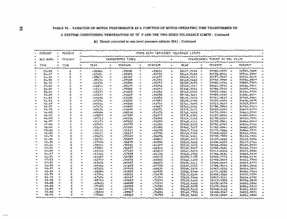
TABLE VI. - VARIATION OF MOTOR PERFORMANCE AS A FUNCTION OF MOTOR OPERATING TIME TRANSFORMED TO
A PREFIRE-CONDITIONING TEMPERATURE OF 70" F AND THE TWO-SIDED TOLERANCE LIMITS - Continued
(b) Thrust corrected to sea-level pressure altitude (PA) - Continued
""""""""""~""""""""""""""""""""""""""""""""""""~""""-"--"""""""""~"-" - PERCENT - PEHCEiJT - C A N S WITH TWO-SIDED TOLERAYcE LIVITS - - WEB BURN - TAILOFF - TRANSFORMED TIMES - TRANSFORHFn THRUST AT PA= lU.70 - - - """"""_"""""""""""""""""""""""""""""""""--"""~"-"""--""" - - """""_""""""""""""""""~~"""""""""-~"""""""-""~"""~-""""~-" - T I Y E - T I u E - !4EAN - MINIMUY - YhXIMUM - MEAN - uIvIMI IY - UAXIUIJU - ~""""""~""""""""""""""""""""""""""""""""~""""""~""""""-"""""""""--"""
33.59 34.37 3 5 - 1 6 35.94 3b. 72 37 50 3B.ZH 39.06 39.84 4d.62 u1.41 42.19 42.97 43.75 44.53 45.31 46.09 40.87 47.66 48.44 49.22 50.00 50.78 51.56 52.34 53.12 5 3 - 9 1 54.65, 55.47 50.25 57.03 57-81 58.59 59.37 bO.16 60.94 61.72 62.50 63 28 64 e 06 64 84 65.62 b6.'+1
0 0 0 0 0 0 0 0 0 0 0 0 0 0 0 0 0 0 0 0 0 0 0 0 0 0 0 0 0 0 0 0 0 0 0 0 0 0 0 0 0 0 0
.35090 -35906 ,36722 ,37538 .3R354 -39170
.UO802
.U161R
.4?434
.4406h
.44882 -45698 "46514
.399a6
. U ~ Z S O
.47330
.48146
.4,8962
-50595 .4977R
e51411 -52227 -53043
.54675 ,53059
,55491 . s6307 ,57123 ,57939 ,59755 ,59571 a60387 -61203 .62019
-63651 -64467
-62835
-65283 ,66099 .66915 -67731 .685C7 -69363
32177.2544 - 32123.2479 - 32146.151 1 - 32169.4460 - 32228.8679 - 32209.131 1 - 32396,9041 - 32512.69051 - 3 2 5 ~ 6 . 3 6 2 1 - 3 2 6 9 9 . 1 ~ 9 0 - 32763,2231 - 32741.4no3 - 32770.5171 - 327f,6.41362 - 32772.43PS - 3281b.5142 - 32968.4111 - 3 2 9 ~ 2 . 7 6 0 7 - 33067.7148 - 33109.R799 - 33734.4941 - 332R0.4P73 - 33305.84P6 - 33318.0493 - 33330.9907 - 33368.1992 - 3 3 3 4 1 . 5 0 ~ 0 - 33379.1f475 - 33382.16112 - 33376.6611 - 33372.5635 - 33384.2974 - 33356.9399 - 33315.0234 - 33265.9946 - 33205.16116 - 33165.4482 - 33148.6978 - 33159.5122 - 33168.7759 - 33152.9893 -
3zf,70.0?00 -
32909.2070 -
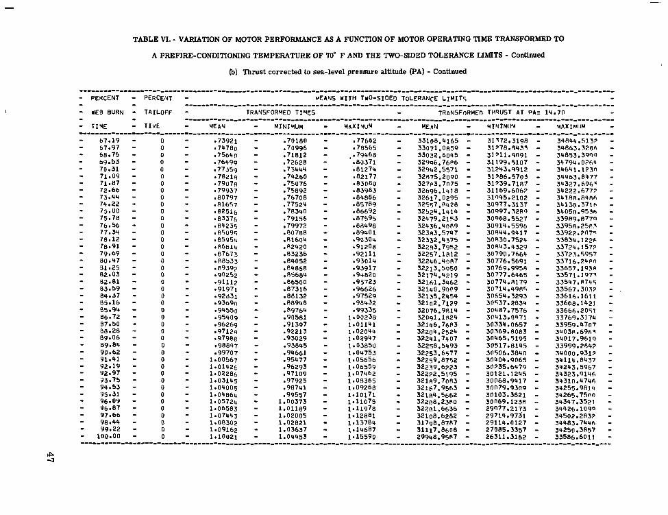
TABLE VI. - VARIATION OF MOTOR PERFORMANCE AS A FUNCTION OF MOTOR OPERATING TIME TRANSFORMED TO
A PREFIRE-CONDITIONING TEMPERATURE OF 70" F AND THE TWO-SIDED TOLERANCE LIMITS - Continued
(b) Thrust corrected to sea-level pressure altitude (PA) - Continued
- PERCENT - PERCENT - M E N S WITH TWO-SIDED TOLERANCE LIMITS - - WEB BURN - TAILOFF - TRANSFORMED TIMES - TRANSFORMED THQUST AT PA= 14.70 - - T I Y E - TIME - YEAN - MINIMUM - M A X I M U M - MEhN - YINrMUY - M A X I M l l M -
...................................................................
- - .....................................................
- - .....................................................
-""""""~""""""""""""~""""""~""""""""-"--"""""""""""""""""""~"""""""""~ 67.19
68 75 67.97
69.53 70.31 71.09
72.66 71.87
73.44 74.22 75.00 75.78 76.56
78.12 77.34
79.69 80.47 81.25 82.03 82.81 83.59 84.37 65-16 85 94 86.72 97 50 88.28 89.06 89.81) 90.62
92 19 91.41
92.97 93.75 94.53 95.31 96.0Y 96.87 97.66 98.44 Y9.22
100.Q0
re.91
0 0 0 0 0 0 0 0 0 0 0 0 0 0 0
0 0
0 0 0 0 0 0 0 0 0 0 0 0 0 0 0 0 0 0 0 0 0 0 0 0 0 0
. 7 0 m e70996 ,71812 -72628 ,73444
79260 -75076 75892
,76708 -77524
.79156
.80788
.81604
78340
79972
e82420 ,03236
.81)868
.84052
85684
-87316 ,88132 88948
,89764
-86500
,91397 -92213 -93029 ,93845 .94661 ,95477 ,96293 e97109
,90581
-97925 -98741 ,99557
1 00373 1.01189 1.02005 1.02821
l .OW53 1.03637
33108.4165 - 33032.6045 - 33071.0859 - 329~6.76P6 - 32942.5571 - 32875.2090 - 32617.0295 - 32696.1418 - 32557.P428 - 32524.1414 - 32479.2153 - 32436.40P9 - 323A3.5747 - 32332.4375 - 322~3.7952 - 32257.1812 - 32213.5950 - 32174.4219 - 32161.3462 - 32135.2454 - 32076.9814 - 32091.1R24 - 32146.76$3 -
327~3.7075 -
32246.4nR7 -
321~0.9009 - 321n2.7129 - 32204.2524 - 32241.7407 - 32258.5493 - 32253.6577 - 32259.8752 - 32259.6223 - 32222.5195 - 32189.7083 - 32184.5662 - 32167.9563 - 32208.23PO - 32201.6636 - 32108.6282 - 31798.87R7 - 29948.95P7 - 31117.8608 -
34RW.Sl33 34863.5286 34853,3900 34794.0764 34641.123n
34327.h9h7 34463,8477
341RR.fl486 34222.6777
34138.3716 34050.9536 33989.877Q 33958.2583
33834.122h 33724.1577 33723.5957 33716.24Rn 33657.193R
33547.R745 33571.1977
336lh.1611 33668.1423
33769.3174
3403fl.6967 34017.9619
34000.9317 33999,2841
34243.5967 34114.R437
34323.9146
34255.9814
34347.3521 3'1426.1099 34502.2832 34483.7446
33586.6011 34250.3857
33922.~n75
3 3 5 6 7 . 3 0 ~
33666.2051
33959.4707
34310.4746
34265.7500
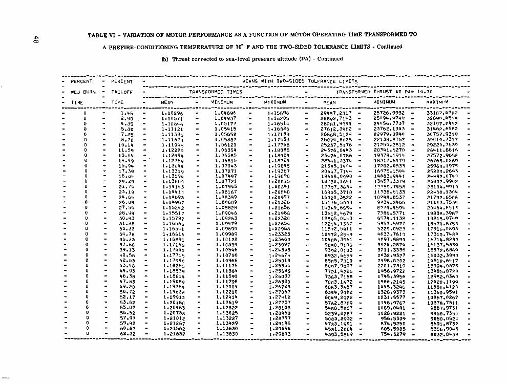
TABLE VI. - VARIATION OF MOTOR PERFORMANCE AS A FUNCTION OF MOTOR OPERATING TIME TRANSFORMED TO
A PREFIRE-CONDITIONING TEMPERATURE OF 70' F AND THE TWO-SIDED TOLERANCE LIMITS - Continued
(b) Thrust corrected to sea-level pressure altitude (PA) - Continued
- PERCENT - PERCENT - MEANS WITH TWO-SIDED TOLERANCE LIHITS, - - WEd BURN - TAILOFF - TRANSFOHMED TIMES - T R A N S F ~ R Y E P THQUST AT PA= 14.71) - - TIYE - TIME - MEAN - MIPlIYUM - MFXIHUM - MEAN - VINIMUW - MAXIMIIM - - - """"""_"""""""""""""""""""""""""""""""""""""""""""""" - - ......................................................
"""""""""""""""""""""""""""""""""""""""""""""""""""""-"""""""""""" - 0 0
- 1.45 - 1.10296 - 1.04696 - I t 1 5 8 9 6 - 29957,2317 - 25726.9932 - 33187.471):, - - 2.90 , - 1.10571 - 1.04937 - 1.16205 - 28892,7153 - 25n94.9749 - 3269n.455'3 - - 0 - 4.35 - 1.10846 - 1.05177 - 1.16514 - 28281.9094 - 2bQ56.7737 - 32107.0457 - 0 - 5.80 - 1.11121 - 1.05415 - 1.16826 - 27612.3962 - 23762.1545 - 31462.658? - - 0 - 7.25 - 1.11395 - 1.05652 - 1.17139 - 26868.5129 - 22979.0940 - 30757.9311 - 0 - 8.70 - 1.11670 - 1.05887 - 1.17453 - 26074.fln35 - 22138.n752 - 300111,7317 - 0 - 10.14 - 1.11945 - 1.06121 - 1.17768 - 25237.5176 - 21354.2812 - 29220.7530 - 0 - 11.59 - , 1.1222n - 1.06354 - 1.18085 - 2 4 3 7 6 . 6 ~ ~ 3 - ~ O W I . K ~ - 28411.661~, - 0 - 13.04 - 1.12494 - 1.06585 - 1.18409 - 23476.0786 - 19579.1914 - 27572.965P - 0 - 14.49 - 1.12769 - 1.06815 - 1.18724 - 22541,3374 - 18717.6479 - ~ 6 7 6 5 . 0 2 6 0 - - 0 - 15.94 - 1.13U44 - 1.07043 - 1.19045 - 2 1 5 ~ 5 . 1 1 + ~ - 1 7 2 0 2 . 0 ~ 3 - 2 5 9 6 ~ . 1 9 7 ~ i - - 0 - 17.39 - 0
1.13319 - - 16.64 - 1.07271 - 1 . 1 3 5 9 ~ - 1.19367 - 2 0 6 4 7 . 7 1 ~ - 1 6 n 7 5 . 1 5 a ~ - 2522n.2691 -
1.07497 - 1.19690 - 1 9 6 ~ 0 . 0 0 9 0 - 1 ~ ~ 8 3 . 9 4 4 1 - 2 4 ~ 9 2 . 0 7 4 n - 0 - 20.29 - 1.138hq - 1.07721 - 1.20015 - 1 8 7 3 0 . 1 6 ~ 1 - 13657.3379 - 23802.99172 - 0 - 21.74 - 1.14143 - 1.07945 - 1 *20341 0 - 23.19 - 1.1441Q - 1.00167 - - 1 7 7 q 7 . 3 6 ~ 4 - ! 7 " 9 . 7 4 5 8 - 2 3 1 0 4 . ~ 1 n - 0 - 24.64 - 1.20668 - 1 6 ~ ~ 5 . 3 7 1 8 - 11338.6133 - 2 2 4 ~ 2 . 1 3 0 4 - 0 - 26.09 - 0 - 27.54 - 1.15242 - 1.09820 - 1.21656 - 14369.6554 - 8'74.4594 - 20464.8513 - 0 - 28.99 - 1.15517 - 1.09046 - 1.21988 - 13612.4679 - 7Sfl6.5571 - 19838.398' - 0 - 30.43 - 1.15792 - 1.09263 - 1.22320 - l289S.0443' - 6574.113R - 19215.9740 - 0 - 31.08 - 1.16066 - 1.09479 - 1.22659 - 12214.1367 - 5'357.5977 - 18570.675R - 0 - 33.33 - 1.16341 - 1.09694 - 1.22988 - 11572.5911 - 5229.0923 - 17916.089'3 - 0 - 34.78 - 1.16616 - 1.09909 - 1.23323 - 10972.2549 - 4633.7610 - 17310.74An - - 0 - 36.23 - 1.16891 - 1.10122 - 1.23660 - 10406,3561 - 4 ~ 1 9 7 . ~ ~ 9 0 - 16714.823n - 0 - 37.68 - 1.17166 - 1.10334 - 0 - 39.13 - 1.17440 - 1.23997 - 9 ~ 8 0 . 9 1 n 6 - 3624.2874 - 16137.533'2 -
1.10546 - 1.24335 - 9392.0103 - 3211.3336 - 15572.6fl6Q - 0 40.58 - 1.17715 - 1.10756 - t .2b674 - 8932.6659 - 2032.9327 - 15032.399n - - 0 - 42.03 - 1.1799n - 1.10966 - 1.25013 - 85n5.7310 - 2498.A202 - 14512.6417 - 0 - 43.48 - 1.18265 - 1.11175 - 0 - 44.93 - 1.18539 - 1.11384 - 1.25695 - 7721,4225 - 0 - 46.38 - 1.18814 - - 0
1.11591 - 1.26037 - 7363.7158 - - 4 7 - 8 3 - 1.19089 - 1.11798 - 1.26380 - 71jo3.1672 - 1745.3956 - 12982.n3hn - 0
1586.2145 - 1P420.119'2 - - 49.2B - 1.19364 - 0
1.12004 - - 50.72 - 1.19638 - 1.12210 - 1.26723 - 6663.3687 - 1445.3246 - 11881.4124 - 0 - 52.17 - 1.27067 - 6344.9482 -
1.19913 - 1328.9373 - 11360.9591 - 1.12414 -
0 - 53.62 - 1.27412 - 6049.2922 - 1.20188 - 1.12619 - 1.27757 - 5762.8789 - 1231.5577 - 10867.0267 -
0 - 55.07 - 1.20463 - 1.12822 - 1.28103 - 5488.5067 - 1146.9767 - 10378.7011 - 0 - 56.52 - 1.20738 - 1089.04nt - 9887.9731 -
1.13025 - 1.28450 - 5239,8287 - - 57.97 - 1.21012 - 1028.9221 - 9950.7354 - 1.13227 - 1.28797 - 5003.2932 -
0 - 59.42 - 1.21287 - 1.13429 - 1.29145 - 9783.1991 - 956.5339 - 9050.0524 - 0 - 60.87 1.21562 - 1.13630 - A74.5250 - R691.8732 - 0 62.32 - 1.21857 - 1.13830 - 1.29843 - 4393.5859 - 1.29494 - 4581.2064 - 805.5085 - 0356.9043 -
754.3279 - 8032.843A - . . . . . . . . . . . . . . . . . . . . . . . . . . . . . . . . . . . . . . . . . . . . . . . . . . . . . . . . . . . . . . . . . . . . . . . . . . . . . . . . .
- - - - - - - - - - - - - 1.14693 -
1.14967 - l.nfl389 - 1.20997 - 1 6 0 2 0 . 3 5 ~ 2 - 10m8.0537 - 21792.65nh - 1.00609 - 1.21326 - 15176.5000 - 9739.2466 - 21113.753Q - - - -
- - - - - - 1.25354 - 8097.9097 - 2201.7319 - 13994.0875 -
1956.9722 - 13485.877A - - - - - - - - - 0 - - -
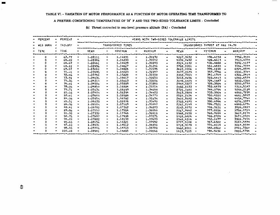
TABLE VI. - VARIATION OF MOTOR PERFORMANCE AS A FUNCTION OF MOTOR OPERATING TIME TRANSFORMED TO
A PREFIRE-CONDITIONING TEMPERATURE OF 70" F AND THE TWO-SIDED TOLERANCE LIMITS - Concluded
(b) Thrust corrected to sea-level pressure altitude (PA) - Concluded
. . . . . . . . . . . . . . . . . . . . . . . . . . . . . . . . . . . . . . . . . . . . . . . . . . . . . . . . . . . . . . . . . . . . . . . . . . . . . . . . - PERCENT - PERCEtuT - MEANS WITH TWO-SIDED TOLERAtltE LIYITs - - WE3 BURN - TAILOFF - TRANSFORMED TIMES - TRANSFORMED THRUST AT PA= 14.70 - - TIYE - TIME - MEAN - MINIYUM - MhXIMUM - MEAN - MI'IIMUW - MAXlWJv - . . . . . . . . . . . . . . . . . . . . . . . . . . . . . . . . . . . . . . . . . . . . . . . . . . . . . . . . . . . . . . . . . . . . . . . . . . . . . . . . .
- - . . . . . . . . . . . . . . . . . . . . . . . . . . . . . . . . . . . . . . . . . . . . . . . . . . . . . . . . . . . . . . . . . . . . . - - """""""""""""""""""""""""""""~""""""""--"--""""--"--"-------- - 0 - 63.77 - 1.22111 - 1.14051 - 1.30192 - 4227.3832 - 696.42313 - 7758.3'436 -
0 - 65.22 - 1.22386 - 1.14230 - 1.30542 - Q070.0492 - 626.6613 - 7513.437n - 0 - 66.67 - 1.22661 - 1.14429 - 1.30893 - 3914.1132 - 536eRO88 - 7291.4177 - 0 - b8.12 - 1.22936 - 1.14627 - 1.31244 - 3758.0951 - 461.4833 - 7054.7n7n - 0 - 69.57 - 1.23210 - 1.14826 - 1.31595 - 3610.0066 - 394.1198 - 6825.8935 - 0 - 71.~1 - 1.23485 - 1.15023 - 1.31947 - 3477.0535 357.7756 - 6596.3315 - 0 - 72.46 - 1.23760 - 1.15220 - 1.32300 - 3333.7065 - 341,1709 - 6526.2419 - 0 - 73.91 - 1.24035 - 1.15417 - 1.32653 - 32n3.0496 - 323.4413 - b082.657n - 0 - 75.36 - 1.2431n - 1.15613 - 1.33006 - 3078.1025 - 324.1687 - 5832.0360 - U - 76.al - 1.24589 - 1.15809 - 1.33360 - 2959.5327 - 328.3924 - 5590.67~1 - 0 - 78.26 - 1.24850 - 1.16004 - 1.33714 - 2832.1033 - 353.6~79 - 5310.51R7 - 0 - 81.16 - 1.25400 - 1.16394 - 1.34423 - 2613.0569 - 0 - 82.01 - 1.25683 - 1.16588 - 1.34779 - 2516.2124 - 350.9310 - 4681.59'57 - 0 - 84.06 - 1.2595q - 1.16782 - 1.35139 - 2422.55R2 - 786.3424 - 4~5~.771m - 0 - R5.51 - 1.26233 - 1.16976 - 1.35490 - 2333.41P5 - 390.4996 - 4276.3377 - 0 - 86.96 - 1.26508 - 1.17169 - 1.35847 - 2242.21'48 - 394.752.1 - UO89.677u - 0 - 88.41 - 1.26782 - 1.17362 - 1.36203 - 2155.6772 - 386.3121 - 3925.0427 - 0 - 89.86 - 1.27057 - 1.17554 - 1.36560 - 2067.9942 - 377.9156 - 3758.0729 - 0 - 91.30 - 1.27332 - 1.17746 - 1.36918 - 19~18.2938 - 368.7698 - 3607.817R - 0 - 92.75 - 1.27607 1.17938 - 1.37275 - 1918.6824 - 360,2729 - 3477.0930 - - 0 - 94.20 - 1.27882 - 1.18130 - 1.37633 - 1940.4316 - 352.1477 - 332P.7156 - U - 95.65 - 1.28156 - 1.18321 - 1.37992 - 1777.5100 - 367.4322 - 31R7.5R79 - 0 - 97.10 - 1.28431 - 1.19512 - 1.38350 - 1718.9n79 - 370.0119 - 3067.803a - 0 - 98.55 - 1.28706 l.lR703 - 1.38709 - 1662.0911 - 382,4562 - 2941.726n - 0 - 100.00 - 1.28981 - 1.18893 - 1'.39068 - 1613.7115 - ?98.5434 - 2828.R79h -
- - - - - - - - - - 0 - 79.71 - 1.25m, - 1.16199 - 1.34068 - 2721.1460 - 344.0794 - 5098.2125 - - 333.3904 - 4892.7235 - - - - - - - - - - - - """"""""~""""""""""""""""""""""""""""-"""""~""""""""------""""--"--"----"--
TABLE M. - VARIATION OF MOTOR PERFORMANCE AS A FUNCTION OF MOTOR OPERATING TIME TRANSFORMED TO
A PREFIRE-CONDITIONING TEMPERATURE OF 140" F AND THE TWO-SIDED TOLERANCE LIMITS
(a) Chamber pressure
. . . . . . . . . . . . . . . . . . . . . . . . . . . . . . . . . . . . . . . . . . . . . . . . . . . . . . . . . . . . . . . . . . . . . . . . . . . . . . . . . . . . . . . . . . . . . . . . . . . . . . . . . . - PERCENT - PERCENT - MEANS WITH TWO-SIDEn TOLERANCE L I u I T S - - - . . . . . . . . . . . . . . . . . . . . . . . . . . . . . . . . . . . . . . . . . . . . . . . . . . . . . . . . . . . . . . . . . . . . . . . . . . . . . . . . . . . . . . . . . . - WE3 BURN - TAILOFF - TRANSFORMED T I M E S ~ S E C - T P ~ U S F O R M E ~ CHhHBE4 PRESSUREoPSIL - - T I V E - - . . . . . . . . . . . . . . . . . . . . . . . . . . . . . . . . . . . . . . . . . . . . . . . . . . . . . . . . . . . . . . . . . . . . . . . . . . . . . . . . . . . . . . - T I V t - MEAN - MINIWJM - M A X I M U M - MEAN - UI'IIUU'4 - UAXIM!P - . . . . . . . . . . . . . . . . . . . . . . . . . . . . . . . . . . . . . . . . . . . . . . . . . . . . . . . . . . . . . . . . . . . . . . . . . . . . . . . . . . . . . . . . . . . . . . . . . . .
.oo
1-56 .78
2.34 3.12 3-91 4.69 5.47 b.25
7.81 7.03
a . w 9.37 10.16 10.94 11.72 12.50
14.06 13.28
14.84 15.62 16.41 17-19 17.97 18.75
20.31 19.53
21.09 21.87
23.44 22.66
24.22 25.00 25.76 26 56 27.34 28.12 28.91 29.69 30.47 31.25 32.03 32.81
0 0 0 0 0 0 0 0 0 0 0 0 0 0 0 0 0 0 0 0 0 0 0
0 U
0 0 0 0 0 0 0 0 0 0 U 0 0 0 0 0
0 0
.oooon
.00814
.0162S
. 0 2 ~ 3 -03257
.04885
.04071
-05699 -06514 -07329 - 0 8 1 4 2 -08956 09770 lob05 .1139, .1221? -13027 -13641 -14656 1547n 162R~ -17094 -17912
-19541 . I0727 -20355 -211h9 .219R3 e2279P
~2442h ,23612
-25240 .26051( -268611 .27bP3 -28497 ,29311 -30125 3093s 31754 -32568
,34196 33382
.ofloo0
-0 1546 .on773
,02319 ,03092
.0463fl -05865
.a5411
.06184 06957 .0773n
. 1 n o u ~
.lo822 . 1 1595 12368
,13914 .13141
.14687 ,15460 .16233 .17006
- 1 8552 .17779
.19325
.OR503 -09276
.20098
.a1871
.2 1644
.22417
.73190
-24736 ,23963
25509 ,26282 -27055 ,2782R .2A601 e29374 ,30147 -30920
.32466 ,31693
.ooooo e00855 -01711 02566 -03422
-05132 -04277
-05988 .Ob843 07h99 .08554 ~09409 10265 ,11120 -11976 12R31 13686 -14542 .15397 -16253 ,17108 17963 .18819
,20530 -19674
,21385 ,22240 -23096 ,23951
25662 -24907
.26518 ,27373 -28228 .2908u
.30795 -29939
-31650 -32505 33361 -34216
-35927 ,35072
100.'4337 - 295.3759 - 513.3419 - 728.8R90 - 322.5771 - 1198.73P2 - 1075.6hU8 - 1289.0778 - 1351.7128 - 13~9.9962 - 1410.4PP5 - 1420.7509 - 1425.59fll - 14p6.9PqO - 1477.2773 - 1425.7977 - 14?6.3?"1 - 1428.0669 - 1429.3379 - 1430 .OS30 - 1430.77R2 - 1431.3210 - '1432.5235 - 1434.2267 - 1436.2723 - 1437.61?42 - 1435.6745 - 1426.7016 - 1421.0263 - 1418.5203 - 1416.1169 - 1414.6n39 - 1413.1396 - l'b12.2903 - 1412.2309 - 1412.8966 - 1413.6395 - 1414.8231 - 1416.2446 - 1418.1979 -
1425.~7~3 -
1477.7n16 - 1~31.5~60 -

TABLE VII. - VARIATION OF MOTOR PERFORMANCE AS A FUNCTION OF MOTOR OPERATING TIME TRANSFORMED TO
A PREFIRE-CONDITIONING TEMPERATURE OF 140" F AND THE TWO-SIDED TOLERANCE LIMITS - Continued
(a) Chamber pressure - Continued
- PERCENT - PEPCE 4T - VrEANS WITH TWO-SIDED ToLCRArlcE L I V I T q - - #E3 BURN - TAILOFF - T~~ANSFORMED TIMESOSEC - THANSFORMEP CHbMBER PRFSSIIPEOPSIA - - T I Y E - T 1 ,.a€ - HEAN - M I Y I W M - MAXIYUM - VEAN - MIY.IVI~IY - V A X I M l l M - """"""""""""~"""""""""""""""""""~-""""""""""""~~"""""""~"""""""""""~" - 33.59 - - 34.37 - 0
0 -3501n - ,33239 - -36782 - 1420.0132 - 1351.?127 - 1484.814? - .35825 - -34012 - - 55.16 - -37636 - 1422.4617 1'55.4H23 -
0 1490.4411 -
- 35.94 - -36631 - ,34785 - .39493 - 1424.7729 - 1358.3451 - 0 .37453 - .35558 - 1491.1 OQ7 -
,39349 - 1427.6518 - - 36.72 - 0 .38267 - .3h331 - 176n.3nh7 - 1494 .0Q60 - - 37.50 - 0
.40204 - 1430.5358 - .390€!1 - 1361.3~6n -
,37103 - 11190.7157 - - 38.28 - 0
-41059 - 1432.9190 - 1763.3341 - .39b9, - 1502.513Q -
- 33.06 - -37876 - .41915 - luy+.7pn2 - 1364.33n3 - 3 .ltn71n - 1sn5.2311 -
-38649 - - 39.84 - "42770 - 1436.R444 - U .4152q - 1366.4675 -
-39422 - 15~17.2217 - - 40.62 - 0
"t.5626 - 1478.9Q12 - l368.9QhP - ,4233- - 1snn.ww -
.40195 - - 41.41 - 0 ,44481 - 1441.9523 - - -4315; - .4096P - 1773.0652 - lS11.639r1 -
- 42.19 - .4333r, - lU44.5722 - 1777.7049 - 0
1511.34QU - - 42.97 - 0
,41741 - .46192 - 1446.9fih'I - .447e1 - 178n.695n -
.4?514 - 1 5 1 3 . 7 3 ~ ~ - - uj.75 - .47n47
0 1449. 1724 - 1382.3127 - 1516.n37n -
- 44.53 - .(tSS45 - 0
-411287 - -47903 - 1'4<1.2Q44 - .461(0': - .44060 - 1?83.9?PQ - 1519.7rln-, -
- 45.31 - .49758 - 0
lU53.2760 - 1'83.5R47 - 1527.P573 - e472711 - - 46.05, - 0 .4RU3? - ,44833 - .4,3bl.S - 1455.4254 - 1384.31511 - 15Eh.5355 -
- 46.87 - 0 -45606 - ,50469 - 1457,6419 -
-48b57 - 1'96.0459 - .4637a - 1527.2370 -
-51324 - 1459.0P15 - - 47.bb - 0 1387.9541 - 1sw.2nqn -
- 49.44 - 0 ~ 4 9 6 6 6 - -47152 - .52180 - l u h 0 . 2 ~ 0 6 - 1300.9665 - 153Q.Cl7a - . ~ + B O - .47925 - - 49.22 - 0
,53035 - 1461.4136 1P89.5243 - .512q4 - ..4fl699 - 1533.3020 -
- 50.00 - 0 . 5 3 ~ 9 0 - l r42.5ot19 - 1390.032Q -
. 5 2 1 n ~ - ,49471 - 1535.15fi9 - - 5d.78 - 0
.54740 - I ~ + ~ J . H ~ ~ I I - 1387.5966 - 154n.ln77 - - Sl.56 - ,52923 -
0 ,50244 - 5S60 1 - 1465.4547 - 1385.7526 - 1545.15hQ -
- 52-34 - ,53737 - 0
,51017 - -56457 - 1466.2470 - 1383.7610 - 1549.7331 - ,54551 - -51790 - - 53.12 - 0
,57312 - 1466.9521 - 1383.9927 - - .5536'5 - 1549.9116 - - 53.91 - 0
-57563 - -58167 - 14h7.5312 - 1385.9142 - -5610n - 1543.24Hl -
- 54.bY - .53336 - 0 .5699!~ - a59023 -
,54109 - .5JH7H - 1468.0953 - 1'+67,85?7 - 1786.3Ul'+ - 154?,367q - - 55.47 - 0 ,57808 - ,54882 - ,60734 - 1468,9139 - 1386.54ha - 1540.6440 - - 56.25 - 0 - ,58622 - 1.387.4Q59 - 1550.331q -
-55655 - -6158Y - 1469.45h1 - 1387.6922 - 1551.2201 - - s7.03 - 0 .5943h - ,56428 - -62444 - 1469.7399 - 1388.1656 - 1551.3141 - - 57.81 - 0 -60251 - ,57201 - -633GO - 1469.9770 - .178R.7000 - 1551.11thrl - - 38.59 - 0 - -61l165 - .57974 - - 53.37 - -64155 - 1469.6545 - 0
138R.7893 - 1559.5197 - - 60.16 - 0
-61879 - ,58747 - -65011 - 1468.9440 - 1'88.5530 - 1549.235P - -62693 - -59520 - - b0.94 - U .6n293 - -66721 - 1468.5672 - -65R66 - 1468,7596 - 1387.6791 - a63507 - - 31.72 - 1386.9767 - 1550.157C -
- 62.50 - 0 0
-64322 - -6106h - e67577 - 1467.9619 - 1387.fi300 - -65136 - -61839 - 154t4.292Q -
- 53.28 - -68432 - 1467,lPPO - 1389.2505 - 0
1545.11JC - ,62612 - -65,288 - 1466.4005 - 1'89.1503 - - 54.06 - 0 - ,66764 - 1305,9956 - 1543.92".0 - 1543.65P7 - -63385 - - 64.84 - e70143 - 1464.9622 -
0 -6757a - - 65eb2 - .64158 - -70999 - 1463.83P3 - 1380 .T3CO - 0 -68393 - 1547.4461 -
- 66.41 - .64931 - 0 -69207 - .65704 - -71854 - 1461.R198 -
-72709 - 1459.2677 - 1374.0556 - 1snq.5altn - ---"""-""----""""--""---"""""""-""""~""""""""""""""""""""""""""""""""""~"~
...................................................................
- - """-""""""""""""""""~""~"""""-""""""""""""~"""""""""""~~ - - """"""""""""""""""-"""""""""~"""""~"""""""""""""""""~"-
- - - - - - - - - - - .43Yb7 - - - - - - - - - - - - - - - - - - - - - - 1s49.84n? - - - ,659511 - - - - 1367.3275 - 1551.2n70 -
u1 CI
TABLE VII. - VARIATION OF MOTOR PERFORMANCE AS A FUNCTION OF MOTOR OPERATING TIME TRANSFORMED TO
A PREFIRE-CONDITIONING TEMPERATURE OF 140" F AND THE TWO-SIDED TOLERANCE LIMITS - Continued
(a) Chamber pressure - Continued
""""""""""""""""""""""""""~"""""~""""""""~""""-~""~--"~--"--""""--~---"--""-- - P E ~ ~ C E N T - PERCEIJT - 'JEANS WITH TWO-SIDED TOLERANCE L I V I T ~ - - *Ea BURY - TAILOFF - THANSFOQMED TIMESeSFC - T R A N S F O R V E ~ CIlfiMRFQ PRFSSUQEePSIA - - T I T - TIWE - MEAN - M I N I W M - M I \ X I Y U M - K A N - VTLlIM114! - UAXI'."!M - - 67.19 - 0 - -70021 - -66477 - -73565 - 1456.5565 - 1763.5n7n - 1549.606n - - 67.97 - 0 .70835 - -67250 - -74420 - 1rt5~.324a - 1360.4239 - 1547.P25P - - 69.53 - 0 - -72463 - -68796 - -76131 - 14sO.43PR - 1759.6978 - 1541.199n - - 70.31 - 0 - -7327~ - .6Q569 - .769@b - 1447.9p3h - 1758.9235 - 1536.9n'h - - 71.09 - 0 - e74092 - .70342 - -77P.42 - l w 5 . 0 n l O - 1357. w + o 1 - 1532.361n - - 71.87 - 0 - -74906 - -71115 - ,78697 - 1442.1234 - 1355.2095 - 152Q.0373 - - 72.66 - 0 - ,75720 - ,71889 - .79553 - 11439.9717 - 1753.574R - 152h.06qe - - 13.44 - 0 -76534 - -72661 - .80409 - 1437.7S71 1352.n~~q - 1521.F.901 - - 14.22 - 0 - .773Qq - .73434 - -81265 - 1435.9QPO - l751.70S5 - - 75.00 - 0 - -7R163 - ,74207 - -82119 - 152fl.2nt.h - - 15.7u - 0
1434.lQt.6 - 1351.545R - 151h.7474 - - 76.56 - ,78977 -
0 .7U980 - .e2974 - 1431.9759 - 135n.9m3 - 1512.Q9Ic. - - e79791 - .75753 - .a3830 - 1430.0538 - 1~5n.6567 - - 17.34 - 0
15n9.451F. - - 7a.12 - 0
-8Ob0q - -76526 - .8(+685 - 1Q28.9775 - 1352.9629 - - . R l 4 2 n - -77299 - .85540 - 14?7.84ns - 1753.93R9 - 15111.7479 - 1 5 t - 1 4 . ~ ~ ~ - - 78.91 - 0 - 79.69 - -82234 - .7R072 - .ab396 - 1427.1032 - 1353.7736 - 15nn.432n -
0 - .03u4[1 - $79845 - -87251 - 1426.3542 - - 90.47 - 1352.2715 -
i) 1500.436'3 - - .R3b62 - ,79618 - .88107 - 1475.59Pl - 1348,9604 - 15112.335m - - 31.25 - 0 - 32-03 - 0 - -85491 - .81164 - -83017 - 1424.Rn65 - - U2.81 - I W R . ~ ~ R ~ -
0 15n1.2627 -
- 83.59 - . .~63n5 - ,81937 - -90673 - 14.24.4n41 - 1348.7n3s - 1500.1047 -
0 - 84.37 - - 85-16 - 0 0
,87937 - .a3483 - .92384 - 1423.7354 - 1346.4419 - 15nl.n2w - - 85.94 - .A8747 - .e4256 - a93239 - 1423.9PP6 - 1346.6436 - 1501.7337 -
0 - -89562 - .AS029 - -94094 - 1423.8R17 - 1346.4755 - 1 5 n 1 . 2 ~ ~ ~ - _- 36.72 - - - b7.50 - 0 -90376 - -85802 - .9*950 - 1423.5669 - 1348.177R - 1490.955Q - 0 - ,91190 - -86575 - ,95805 - 1422.7561 - 1347.7R11 - - 38.28 - 0 - 89.06 - 0 - -92810 - .a9121 - -97516 - 1421.9058 - l"42.6855 - - 69.84 - 0
ISOI .206n - - -93633 - .Ut7894 - -98371 - 1422.3754 - 1?41.3233 - - 90.62 - 0 - .944u7 - -89667 - -99227 1503.4776 -
- 91.41 - 0 14~2.61n6 - - ~95261 - .9nu(to - 1.00082 - 1422.5565 - 1340.5762 - 150u.64rin -
- 92.19 - 174o.lt14n - 0 -96075 - .91213 - 1.00938 - 1422,4056 - 1504.69R9 -
- Y2.97 - 0 1339.396r) - 1505.4157 -
- 93.75 - -96889 - 0
-91986 - 1.01793 - 1422.3544 - 1336.272'1 - 15llA.4364 - - 94.53 - 0
,97704 - .92759 - 1.02648 - 1422.6RQ5 - - -48518 - -93532 - 1.03504 - 95.31 - - 1422.9132 - 1330.1237 - 1515.7027 - 0 - 96.09 - -99332 - .94305 - 1.04359 - 1422.77176 - 1327.9668 - 1517.6747 -
- 96.81 - 0 1.00146 - , -95078 - 1.05215 - 1422.7590 - 1325.8564 - 0 - 1.00960 - .95851 - 1.06070 - 1423.0044 - 1519.6617 -
- 97.66 - 1320.4436 - 0 1.01775 - e96624 - 1.06925 - 1422.0135 - 1525.5647 -
- 98.44 - 0 1.02589 - .97397 - 1312.2954 - 1531.7317 - - 99.22 - 0 - 1.03403 - e9P170 - 1.08636 - 1399.2757 - 1 07781 - 1417.0371 - 1298.3658 - 1535.7085 - - 100.00 - 1272.7731 -
0 1525.77A3 -
""""""-"""""""""""""""""""""""""""""""""""""""""""""""""""""""""""~
- - """""""""""~"""""""""""""""""""~""""--"""-"""""--"""--""-- - - """""~"""""~""""""""~""""""""""""""""""""""""""""""""-- """""_"""""""""""""""""""""""""""""""""""""""""""-""-"---"""---"""--""-- - 68.75 - 0 - -71649 - .68023 - ~75276 - 1452.1513 - 1759.7531 - 1544.55116 - ,
- - - - ,84676 - .80391 - e88962 - 1475.2075 - 1348.2621 - 1502.153n - - - sf37119 - -82710 - a91528 - 14?3.0770 - 1748.3942 - 1499.550q - - -
1497.7317 - .92004 - .8734R - 96661 - 1421.7a59 - 1345.1773 - 149R.39Uq ' -
- -
- - 1332.8120 - 151 2 566o - - - - - 1.04217 - ,98943 1.09492 1361.2664 - 1221.5074 - 150 1 0254 -
TABLE M. - VARIATION OF MOTOR PERFORMANCE AS A FUNCTION OF MOTOR OPERATING TIME TRANSFORMED TO
A PREFIRE-CONDITIONING TEMPERATURE OF 140" F AND THE TWO-SIDED TOLERANCE LIMITS - Continued
(a) Chamber pressure - Continued
"~~~~~""~"""""~~"""""~"~""~~""""""~~~"""~"-~~~"""""""~~""~~""""-----~~""""~-"~""-~--~ - PERCENT - PEHCEdT - UE.ANS WITH TWO-SIDED TOLERANCE L I H I T S - - dE3 BUHFJ - TAILOFF - TRANSFORMED TIMESpSEC - THWSFCRMEP CHAMRE? PQFSSIJREPPSIA - - T I Y E - T I M E - MEAN - M I N I H U H - M A X I W M - MEAN - VIV'IMIIY - Y A X I Y ( l U - - - ""~""""""~"""~"""""--""""--"-~"~""~"~""~"""""----""""--"-"-"""-- - - ~~""~""~"~"""""~~""~"~--"~"-"~~""""""""""~""~~"-~---""""--~"-"""""
1.45 - 2.90 - 4.35 - 5.90 - 7.25 - 8.70 -
11.59 - 10.14 - 13.04 - 14.49 - 15.94 - 17.39 - 18.84 - 20.29 - 21.74 - 24.h4 - 26.u9 - 27.54 - 28.99 - 51.88 - 30.43 - 33.33 - 34.70 - 36-23 - 39.13 - 37.08 -
23.19 -
40.58 - 42.03 - 43.V8 - 44.93 - 46.38 - 47.H3 - 49.28 - 50.72 - 53.62 - 55.07 - 56.52 - 57.97 - 59.42 - 60.87 -
52.17 -
62.32 - """"""""
-99198 ,99451
,90954 -99703
1.00451
1.00942
1.00203
1.00697
l .nt186 1.01429
1.01910
1 . 0 2 3 ~ 6 1 .02622
1.03092
I. 0 3 7 8 ~
1.01b70
1.02148
1.0285R
1.03325 1.0?,557
1.0424R 1.04019
1.04476
1 .04930
1.05381 1.05156
1 so5605
1.06050 1.05828
1 06272 1 06493
1 .n4703
1.06714 1.06934
1.07371 1.07589
1.07153
1.07806 1.04023 1.0P239 1.08454 1 -08669 1.08884 .""""""" ."""""
1342.2156 1320.0136
1264.5977 1293.9075
1232.9754 1198.9454 1162.4666 1173.9962
1044.5777
962.9P10 922.251 5
R42, 5052 sn4.1639
730.4R15 766.6470
bq5.5035 661.8137 679.62P8 5q9.07P9 569.9131 542.1354 515.9361
467.5RS2 445.2673 424.071 1 404.0999 3p5.0070 367.1569 350.3693 334.447s 319.1783
290.9043 304.6530
278.1253 266.0190 254.7610 244.0714 234,1374 224.7769
1 0 ~ 4 . R ~ 6 5
1003 .9a l l
~ 8 2 . 0 2 ~ 2
Qo1.111n
146U.aq4Q 1484.869u
14o1.oonl 1415.2522
1353.1343 1343.7810
1289.18lc. 1321.Abr)3
1255.3572 1222.P161 1191.5301 1159.482q 1127.3650 10?5.516(\
1034 .75~n 1nh5.lcnnu
I O ~ J . Q R F . ~ 972.4935 941.4177 91 n . n 6 w
848.3791 879.4091
Rlq.lRl9 787.96qP 750.1971 729.5297 7 n n . 6 5 7 ~ 672.nQ79
616.0Sha 644.218Q
589.523h 563.8555 539.1412 514.897n
467.9844 490.931U
425.1122 445.@237
404.P453 385.6962 366.9059 350.0154 333.9163 ."""""_
ul w
TABLE VII. - VARIATION OF MOTOR PERFORMANCE AS A FUNCTION OF MOTOR OPERATING TIME TRANSFORMED TO
A PREFIRE-CONDITIONING TEMPERATURE OF 140" F AND THE TWO-SIDED TOLERANCE LIMITS - Continued
(a) Chamber pressure - Concluded
"""""""""""""""""""""""""""""""-"""""-~"""""""""""""""--"""""""""~"-" - PERCENT - PEHCE.qT, - WEANS J I T H TWO-SIDED TOLFRAQCE L I U I T C - - - """"""""""""""""""""""""""""""""""""""""-"""""""""""" - rlEa RURN - TAILOFF - THANSFORYED TIMES,SEC - T Y A M S F O R V E ~ CHAM9FQ PRESSUQEPPSIA - - - """"""""""""""""""""~.."""""""""""""""""""-""~"""""""""~ - T I Y E - T I M MEAN - M I N I Y U Y - M A X I M U M - YFCN - " I ~ I I V I l Y - uhXIMl lu - ...................................................................
0 - b5.22 - 318.n5nf3 - 1.171311 - 1.09311 - 1.24948 -
0 - 66.67 - 207.4773 - 1.17417 - 1 0 9 . v n q - 3115.1337 -
1.09524 - 1.25309 - 0
1s9.5115 - - 68.12 - 1n7.2206 - 1.17704 - 1.09737 - 1.25671
291 .pn211 - 0 - 6 9 - 5 7 - 1.17Y91 - 192.0oa5 - 104.9n90 - 279.2P7" -
1.09949 - 1.26033 - 0 - 71.01 - 1.18278 - 1P5.1175 -
1.101h0 - 102.c)7nu - 267.26U7 - 0 - 72.'+b - 1.18565 - 1.26395 -
1.10372 - 178.44P7 - 100.7621 - 256.155* - 1.26758 - ,172.2978 -
0 - 73.31 - 1.1n5m - 1.27121 - t o n . o w 1 - 244.5flIf1 - 0 - 75-36 - 1.19139 - 1.111793 - lt.6.41aO -
1 e27484 99.0554 - 233.7ans -
0 - 76.81 - 160.0?43 - 98.395s - 1.19429 - 223.2527 -
0 1.11003 - 1.27AUFi - 15S.3nRb - - 78-26 - 1.19712 - 97.657?. - 2 1 2 . 9 ~ m - 1.11213 - 1 -2H212 -
0 - 79.71 - 1 . 1 9 Y 9 ~ - 1.11422 - 1 e2.7577 - 150.2649 - 98.9741 - 201.64C.7 - 145.5537 -
0 - R l . l b - 1.202.9f, - 9fl.')h26 - 19?.1'J40 - 0 - 82.61 - 1.11631 - 1.28942 - 141.24F9 - 99.14fl7 -
1.20573 - 1.11839 - 1P3.3511 - 1.29307 '-
0 - "+.U6 - 137.1?15 - 1.20860 - 99.6onu - 174.6425 -
0 - (35.51 - 1.12047 - 1.21147 - I -29673 -
1.12255 - 133.2316 - 1.30039 - 1on.qow - 166.4576 -
0 - 06.96 - 1.21434 - 129.4971 - 1 00 8291, - 15n.1645 - 1.12463 - 1.30405 -
u - 98.41 - 1.21721 - 126.0279 - 1.12670 - 101.5559 - 1 w . u w s -
1.30772 - 0 - h9.hh - 122.7059 -
1.2200R - 101.9854 - 143.426- - 0 - 91 - 3 0 - 1.12877 -
1.22295 - 1.31139 - 1.13084 - 119.4P71 - 101.92Pn -
1.31506 - 137.0467 - 0 - 92.75 - 116.1955 -
1.225R2 - 101.7923 - 1.13290 - 130.59997 -
0 - 94.20 - 1.22869 - 1.31874 - 113,1909 - 101.4397 - 1.13496 - 124.90R6 -
0 1 32242 - 35.65 - 110.3971 -
1.23156 - 302.5911 - l ln .?n31 - 1,13702 - 1.32610 -
0 - 97.10 - 1.23443 - 1.13907 - in7.8378 - 1.32978 - 1 0 1 . ~ 1 3 - 114.n447 -
IJ - 98.55 - 1.23730 - 1n5.1259 - 1.14112 - 1.33347 - 101.3656 - 108.8Rh- -
0 - 100.00 - 1.24017 - 1.14317 - 1.33716 - 1 o o . n c m - 1 o o . o n v - 102.5U35 - 100.63R3 - ln0.0n59 - lfl4.40R7 -
---"-----"------""""--""--""""""""""""""-""""""""""""""""""""""""""""""""""
- - 0 - b3.77 l . l 6 & 4 3 - 1 . n q o 9 ~ - 1.24588 - 215.71374 - - 112.6241 - - - - - - - - l . lO852 - - - - - - - - - - - - - - - - - - - - -
TABLE VII. - VARIATION OF MOTOR PERFORMANCE AS A FUNCTION OF MOTOR OPERATING TIME TRANSFORMED TO
A PREFIRE-CONDITIONING TEMPERATURE OF 140" F AND THE TWO-SIDED TOLERANCE LIMITS - Continued
(b) Thrust corrected to sea-level pressure altitude (PA)
................................................................... - PESCENT - PERCEtIT - WEANS WITH TWO-SIOED TOLFRANCE L X U I T ~ - - d E 3 BURN - TAILOFF - TQANSFOQME9 TIMES - TRnVSFnR4Fr TYQUST AT PA= 14.7fl - - - ......................................................
- - """""_""""""""""""""""""""""""""""""""""""""""""""""" - T I W - r x - 14EfiN - V I V I V U M - Y A X I M U F - MEr b4 - t ' I h ' I W ( l V - UAXIV l lV - ..................................................................
.0U
.78 1 e56 2.34
3.91 3.12
4.69 5.47 6.25 7.03
R.59 7.81
10.16 9.57
10.94 11.72 12.50 13-28 14.06 14.84 15.62 16.41 17.19 17.97 18.75 19-53 20.51 21.09 21.87 22 e66 23.44 24 -22 25.00
26.56 25.78
28.12 27 54
28.91 29.69 30.47 31.25 32.03 32.81
0 0 11 0 U U 0 0 0 0 0 0 0 0 0
0 0
0
U 0 0 0
U 0
0 0 0 0 0 0 0 0 0 0 0 0 0 0 0 0 0 0
n
.no000
.n'1773
.01546 -02319
03092 -03865 .O4b38 . o w 1 1 .'1hlflU ,06957 .@7730
-09276 ,10049 - 1 Qh27
-12368 11595
.13141 ,13914 -14687 .15460 -1 h233 -17006 ,17779 18552
,19325 ,20098 -20871 -21644 -22417 -23190 -23961 ,24736 -25509 ,26282 -27055 -27828 -28601 ,29374
-30920 .30147
-32466
.na503
,31693
UI UI
TABLE M. - VARIATION OF MOTOR PERFORMANCE AS A FUNCTION OF MOTOR OPERATING TIME TRANSFORMED TO
A PREFIRE-CONDITIONING TEMPERATURE OF 140" F AND THE TWO-SIDED TOLERANCE LIMITS - Continued
(b) Thrust corrected to sea-level pressure altitude (PA) - Continued
"""""""""""""""""""""""""""""""""""""""""~""""""""~"""""""""-"""""" . PE3CENT - FE?CEF;T - \'EANS WITH TWO-SIDED TOL€f?A'\ICE L l V I T q - - dErl DURN - TAILOFF - TRANSFOHMFD TIMES - T R A N S F P R V F ~ THRUST 4 1 PA= 14.7n - - T I Y E - I I W - 'IEAN - M I h l T U U H - M4XIqUM - YEbN - V J \ I I V l I ' 4 - \ 4 A X I t I I J V ' - - - """""""""""""""""""""""""""""""""""-""~""""-""--""""""" - - """"""~""""""""""""""""""""""""""""""~"""""""-"""""""-~ """""""""_""""""""""""""""""""""""""""""""""""""""""""""""""""""""
3J.bY 34.37 35.1b 35.94 36.72 37.5u 33.28 39.06 3Y .84
41.41 40.62
42.1Y 42.97 93.75 44.53 45.31 46.0Y
41.66 40.87
40.44 43.22 50.00 50.78 51.56 32. 34 53.12 5 3 - 9 1 54.6Y 55.47 56.25 57.03 57.81 5d. 59 59.37 60.16 bO -94 61.72 62.50 63.28 69-06 64.84 65.62 66.41
U 0 0 0 0 0 5 0 0 U 0 5 0 0 0 0 0 0 0 U 0 0 0 0 0 0 0 0 0 0 0 0 0 0 0 0 0 0 0 0 0 0 0
-33239 ,34012 .34785 .3555R .3h331 .371ns .37876 .39649 ,39422 .'bo195
-41741 .42514 .4 3287 .44u6n .Qua33 "45606 ,46379 .47152 ,47925 .OF'698 .49471
-51017 .51790 .52563 .53336 .54109 .54882 .55655 e5642R .57201 .57974 .58747 ,59520 -60293 .61066
-62612 -61839
.633R5 -64158 e64931 .65704
. 4 n 9 6 ~
. s n 2 ~
36782 37638
.3'334Y
.vu204
.41n5? "41915 .4?771) -03626 .44481 -45336 -05192
.3au93
.u7047 -47903 .4t3758 .40613 e50469 ,51324 .5218O -53035 .53890 -54746
5560 1 .55457 -57312 e58167 .59nz3 .5307n -60734 -61589 -62444 e63300 -64155 .65011 ,65866 -66721' ,67577 a68432 ,69288 -70143 ,70999 -71854 -72709
33795.5?70 - 33735.sn77 - 33159.4ue2 - 33946.HF92 - 340%5.6??0 - 34175.3P23 - 34212.7719 - 34?67.lnuS - 34?01.4772 - 34536.67611 - 34JQU.962h - 34455.4738 - 34Sn6.7461 - 34'i77,76P6 - 34633.4453 - 34566.6n94 - 347g6.OnPO - 34748.139~6 - 3 4 7 ~ 2 . n 3 1 7 - 34712.09:b -
34766.3718 - 34765.1F,76 - N7a2.5734 - 34779.5@33 - 347p4.7579 - 344n8.3055 - 34A36.9371 - 34S51.0675 - 34866.5nf>3 - 3 ~ y + , e 7 4 5 - 34898.8369 - 34979.6997 - 34954.2708 - .34971.5744 - 34953.ciCl34 - 349n5.0703 - 34995.6P75 - 34836.5474 - 34t173.9n@O - 347h0.5444 - 34696.5142 - 34627.76P6 - 34662,5020 -

TABLE M. - VARIATION OF MOTOR PERFORMANCE AS A FUNCTION OF MOTOR OPERATING nME TRANSFORMED TO
A PREFIRE-CONDITIONING TEMPERATURE OF 140" F AND THE TWO-SIDED TOLERANCE LIMITS - Continued
(b) Thrust corrected to sea-level pressure altitude (PA) - Continued
"""""~""""""~""""""""""""-""""~"~~"""-""-"""~""""""""-""-"""~""-""""--""-- - PERCENT - PERCENT - MEANS WITH TWO-SIDED TOLERANCE LIMITS - - - "~""""""""""""""~"""-"""~"""""""~""~"""""-""~"""---"""--~-"" - YE0 BURN - TAILOFF - TRANSFORMED TIMES - TRANSFORMED THQUST AT PA= 14.70 - - T I Y E - T I M E - MEAN - MINIMUM - MAXIMUM - MEAN - MIVIYUM - MAXIMUM - - - "~""""""~"""""""""""""~"""""~"~"~~""""""""""~"-""--"""--""-- "~""~""~""-""""--"~""-~""~"""""""~"""""~"-""--"""""""""""""~-""""""--"""--"~---
67.19 67 97 68.75
70.31 69.53
71.87 71.09
73.44 72.66
74.22 75.00
76.56 75.78
77.34 78.12 78.91 79.69
81.25 00 e47
02.03 82.01 83.59 04 37 05.16 85.94
87 50
89.06 88.28
90 e62 09.04
91.41 92.19 92 97 93.75 94.53 95.31 96.09
'96 87 97.6b 98.44 99 e22
100.00
86.72
0 0 0 0 0 0 0 0 0 0 0 0 0 0 0 0 0 0 0 0 0 0 0 0 0 0 0 0 0 0 0 0 0 0 0 0 0 0 0 0 0 0 0
-70021 s 70035 -71649 72463
-73278 -74092 -74906 75720
-76534 ,77349 -78163 .78977 7979 1
e81420 -80605
-82234 ,83048
-84676 -83862
~ 8 5 4 9 1 ,86305 -87119 .a7933 ,88747 89562
,90376 -91190 -92004 -92818
,94447 -93633
,95261 e96075 -96889 e97704 -98518 ,99332
1.00146 1 00960 1.01775 1 02589 1003403 1 I 04217
e66477 .67250 e68023 e68796 ,69569 ,70342 ,71115
.72661 ,71888
,73934 ,79207 ,74980 .75753 .76526 e77299 .78072 .78845 e79618 ,80391 ,81164 ,81937 -82710 .e3483 ,84256 ,85029 .e5802 -86575
.88121 ,87348
e89667 .a8894
-90440 -91213 ,91986 ,92759 ,93532 e94305
.95051 ,95078
e96624 .97397
.98943 -98170
73565 e74420 ,75276
76986 ,76131
.77842 e78697 ,79553 .00408 -81263 e82119 e82974 e83830
-85540 ,84685
-87251 ,86396
-88107 ,88962
-90673 -8981 7
e91520 e92384 93239
,94094 ,94950 ,95805 e96661
a98371 -97516
1.00082 99227
1 00938 1.01793 1 e02648 1 03504 1 e 04359 1.05215 1 06070 1 06925 1 07701
1 09492 1 08636
34588.4272 - 34509,8608 - 34420.1226 - 34477.8198 - 34363.4927 - 342~0.8159 - 39215.9165 - 34155.6680 - 34119.5557 - 34095,6187 - 34054.4839 - 34014.1021 - 34004.3730 - 34000.5659 - 34001,8716 - 34005.2812 - 33975,7241 - 33986.0195 - 33972.1099 - 33948.0088 - 33873.7974 - 33907.5562 - 33855.3540 - 33854.6660 - 33864.3228 - 33959.7280 - 33851.9746 - 33850.1064 - 33862.9233 - 33857.8413 - 33885.7446 - 33919.2900 - 33940,9155 - 33939.4009 - 33915.8203 - 33886.0781 - 33864.0161 - 33841.4697 - 33745.8140 - 33465.4365 - 32826.1562 - 31730.7844 -
34553.8945 - 32774.7227 - 32601.2925 - 32607.6367 - 32652r9580 - 32599.0921 - 32702.9351 - 32673.9419 - 32509.7017 - 32618.9258 - 32463.2129 32495.0352 - 32470.5527 - 32418.2310 - 32308.7310 - 32421.4038 - 32459.3975 - 32484.8555 - 32436.8857 - 32453.1577 - 32497.2920 - 32484.4536 - 32312.7627 - 32204.4609 - 32177.3687 - 31954.7705 - 31923.6724 - 31985.2798 - 32030.8052 -
32402.7505 - 32n89.1113 -
32028.4707 - 31937.2876 - 31910.9106 - 31727.4556 - 31703.3594 - 31714.3418 - 31694.8682 - 31614,9536 - 31503.7490 - 30639.8584 - 31230.1089 - 2787b.7178 - 29521.6621 -
36402.131A 36426.496h 36~12.08sn
36203.2871 36355.747h
35903.6899 36024.0503
35813.9072 35001.6343 35775.8984 35696.2021
35609.9731 35638.415n
35620.0151 35579.728f' 35518.8877 35551.165n
35498.2905 35535.1553
35446.9277
35412.361A 35411.564b
35434.8320 35506.2471 35531.9634 35630.3447 35775.8750
35714.9331 35780.2769
35697.37an 35684.8774
35839.2017 36027.6694 36154.5755
36117.298A 36175.4429
36077.2883 36113.0986 36179.190U 36261.519n 36291.0146
35584.8511 36130.6504

TABLE M. - VARIATION OF MOTOR PERFORMANCE AS A FUNCTION OF MOTOR OPERATING TIME TRANSFORMED TO
A PREFIRE-CONDITIONING TEMPERATURE OF 140" F AND THE TWO-SIDED TOLERANCE LIMITS - Continued
(b) Thrust corrected to sea-level pressure altitude (PA) - Continued
TABLE M. - VAlUATION OF MOTOR PERFORMANCE AS A FUNCTION OF MOTOR OPERATING TIME TRANSFORMED TO
A PREFIRE-CONDITIONING TEMPERATURE OF 140" F AND THE TWO-SIDED TOLERANCE LIMITS - Concluded
(b) Thrust corrected to sea-level pressure altitude (PA) - Concluded
"""""""""""""""""""""""""""""""""""""""""""""""""""""""""-"""""""" - PERCENT - PERCEtIT - VEAh'S WITH TWO-SIDED TOLERANCE L I Y I T s - - .VEj BURN - TAILOFF - TRANSFORME3 TIMES - TR6YSFORME@ THQUST AT PA= 14.70 - - T I V Z - 1 I ..E - ' J E A N - M I Y I V U V - Y A X I Y U M - M c b N - MIUIMIJY - VAXIMllM -
(I - 93-77 - 1.16045 - 1.n909~ - 1 . 2 ~ % 3 - 4441.32nu - 731.6693 - A150.9875 - U - 55.22 - 1.17130 - l.O(r311 - 1.24948 4217.47Ql - fi49.3600 - 7785.59711 - 0 - 66.57 - 1.17417 - 1 . n q 5 2 ~ - 1.25309 - 4nq8.1703 - '749.70P7 - 7466.6373 - 0 - 68.12 - 1.17704 - 1.09737 - 1.25671 - 3914.2729 - l r6e .mlq - 71hr).1630 - U - hY.37 - 1.17YOI - 1 . 0 ~ 9 4 9 - 1.26033 - 36~1.0050 - 397.5039 - hAR4.506[r - 0 - 71.111 - 1 . 1 a z 7 ~ - 1.in160 - 1.23395 - 3q72.9~42 - 357.7524 - 65R9.5756 - 0 - 72.46 - 1.18565 - 1.111372 - 1.26758 - 3~13.32119 - 739.0R!i2 - 62R7.5645 - 0 - 73.91 - 1.19b52 - 1.10583 - 1.27121 - 3170.9911 - 320.2042 - 6021.77nl - U - 7'>..;h - 1.1913? - 1.1n793 - 1.27484 - 31773.7163 - 319.4942 - 57U7.03R5 - 0 - 7h.:\1 - 1.19425 - 1.11003 - 1.27840 - 2qn7.7174 - 722.651'3 - 5492.9431 - 0 - 79.,'t, - 1.19717 - 1.11213 - 1.20212 - 2793.3455 - 748.A527 - 5237.9191 - I, - 7Y.11 - 1.19Y9S - 1.11422 - 1.29577 - 2S75.9762 - 738.37175 - 5 0 1 3 . 6 2 1 ~ - - 0 - t-1.15 - 1.2OZP6 - 1.11631 - 1.23q42 - 2558.44P7 - 727-6990 - , 98119.199tJ - U - ",2, #,I - 1.20577 - 1.11839 - 1.29307 - 2U70,P174 - 744.5(r17 - 4597.1330 - U - c4,llb 1.20Shfl - 1.12047 - 1.29673 - 23ROa4?nb - 779.6224 - 43131.21R7 - I, - ; : \ , S I - 1.21147 - 1.12255 - 1.33039 - 2292.bUP6 - 583.67SU - 4201.605P - U - t\b.'jb - 1.7143U - 1.12463 - 1.3U405 - 2205.4f,R3 - 3AH.?427 - 4022.653" - - 0 - IjLI.Ul - 1.21721 - 1.12670 - 1.3d772 - 2122.2443 - 780.32C6 - 386(+.167" - (1 - 71.30 - 1.22295 - 1.11084 - 1.31506 - 1'363.16P8 - 364.tflR't - 3562.2151 - 0 - 92.75 - 1.22bC2 - 1.13290 - 1.31R74 - 1097.5057 - 756.29h7 - 343A.7165 - - U - 94.cc - 1.2206~1 - 1.15496 - 1.322'42 - 1855.2575 - 151.153n - 3319.3140 -
~ 0 . 3 ~ 1 - 3070.9n71 - U - 58.55 - 1.23737 - 1.14112 - 1.33347 - lhb3.9508 - 382.rlR41 - 2995.0175 - 0 - l[!U.uO - i.24u17 - 1.14317 - 1.33716 - lh13.7fi2b - 798.55f.n - 2A2R.Q63' -
- - """"""_"""""""""""""""""""""""""""""""""""""""""""""" - - """"""""""""""""""-"""~"""-""""""""""""""""""""""""""-- """""""""""""""""""""""""""""""""""""""""""""""~""""""".""""""""""" - - - - - - - - - - - - - - - - - IJ - ij9.'lt> - 1.?2U('G - 1.12077 - 1.31139 - 21142.05~0 - 373.1759 - 3710.9W7 - - - - D
U - - 95.55 - - 97.10 - 1.23156 - 1.13702 - 1.32610 - 1778.7RP4 - 1.23443 - '67,6943 -
1.13907 - 1.32979 - 1720.6466 - 3lR9.A6hl - - - """""""""""""""""""""""""""""""""""""""""""""""""""-""""""""""""""
TABLE VIII. - SUMMARY OF MOTOR PERFORMANCE DATA TRANSFORMED
TO SPECIFIC PREFIRE-CONDITIONING TEMPERATURES AND THE
ONE-SIDED AND TWO-SIDED TOLERANCE LIMITS
(a) Transformed to 20" F
Parameter
-___
Time, t, sec: Ignition delay, td
All 17 motors . . . . . . . . . . . . . . . . Ignition category 1 (duplicated only a failed
Ignition category 2 (simulated only a failed
Ignition category 3 (duplicated a failed
. . . . . . . igniter cartridge, 2 motors)
nozzle closure, 7 motors) . . . . . . . . . igniter cartridge and simulated a failed nozzle closure, 4 motors).
ignition conditions, 5 motors).
. . . . . . . . Ignition category 4 (duplicated normal
. . . . . . Thrust rise, tf
All 17 motors . . . . . . . . . . . . . . . . Ignition category 1 (duplicated only a failed
igniter cartridge, 2 motors) . . . . . . . Ignition category 2 (simulated only a failed
nozzle closure, 7 motors). . . . . . . . . Ignition category 3 (duplicated a failed
igniter cartridge and simulated a failed nozzle closure, 4 motors) . . . . . . . . .
Ignition category 4 (duplicated normal ignition conditions, 5 motors) b . . . . . .
Maximum thrust, . . . . . . . . . . tFmax.
Web burn, b . . . . . . . . . . . . . . . . Action, ta . . . . . . . . . . . . . . . . . . Tailoff, ttail . . . . . . . . . . . . . . . . . Total, tt . . . . . . . . . . . . . . . . . . .
" -
~ "
Mean
""
0.047
(a)
,051
(a)
.036
,118
(a)
. 114
(a)
,119 ,701
1.165 1. 341
.606
1.775 -.
c ~" -
Tolerance limits ...
One-sided - -
Minimum ""
0.015
(a)
. 0 30
(a)
,010
.088
(a)
.083
(a)
,085 .537
1.109 1.281 .512 1.729
aInsufficient data to perform statistical analysis bSpecifications: 0.075-second minimum and 0.150-second maximum.
Maximum
0.079
(a)
,072
(a)
.062
.I48
(a)
. 145
(a)
,153 ,866
1.221 1.402 ,699 1.822
. Minimum
0.011
(a)
.027
(a)
.008
.085
(a)
.079
(a)
.079
.521
1.103 1.275 .503 1.124
Maximum "
0.083
(a)
.075
.151
( 3
,149
,159 .E82
1.227 1.408 . IO9 1.821
60
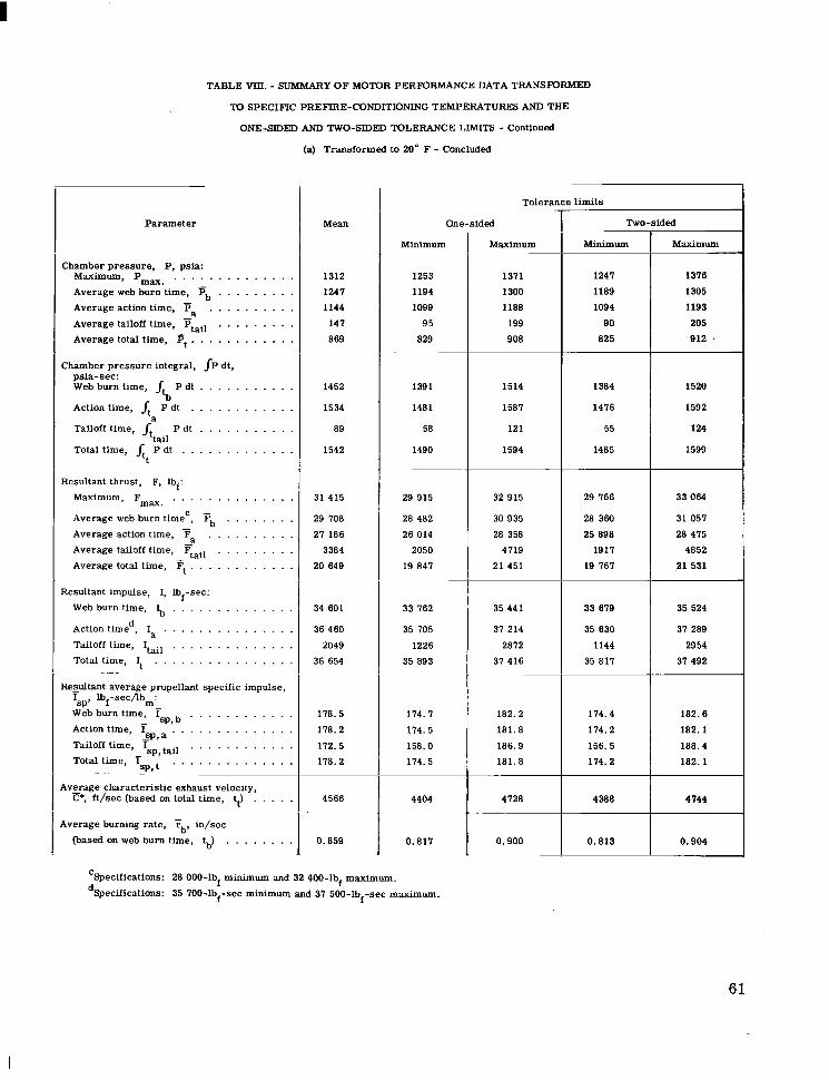
Parameter
TABLE VIII. - SUMMARY OF MOTOR PERFORMANCE DATA TRANSFORMED
'Nj SPECIFIC PREFIRE-CONDITIONING TEMPERATURES AND THE
ONE-SIDED AND TWO-SIDED TOLERANCE LIMITS - Continued
(a) Transformed to 20" F - Concluded
Chamber pressure, P, psia: Maximum, Pma. . . . . . . . . . . . . . . Average web burn time, Pb . . . . . . . . . Average action time, - Pa . . . . . . . . . . Average tailoff time, Ptail . . . . . . . . . Average total time, ?j t " " " " " "
-
-
Chamber pressure integral, JP dt, psia-sec: Web burn time, P dt . . . . . . . . . . . Action time, 4 P dt . . . . . . . . . . . . Tailoff time, Jt P dt . . . . . . . . . . . Total time, ~t~ E i t . . . . . . . . . . . . .
j t b
a
Resultant thrust, F, lbf: Maximum, Fmax, . . . . . . . . . . . . . . Average web burn timec, Fb . . . . . . . . Average action time, Fa . . . . . . . . . . Average tailoff time, Tail . . . . . . . . . Average total time, Ft . . . . . . . . . . . .
-
-
Resultant impulse, I, lbf-sec: Web burn time, 6 . . . . . . . . . . . . . . Action timed, I . . . . . . . Tailoff time, Itail . . . . . . . . . . . . . . Total time, It . . . . . . . . . . . . . . . .
_" ~~
Rezultant average propellant specific impulse, Isp, lbf-sec/lbm: Web burn time, Tsp, . . . . . . . . . . . . Action time, I . . . . . . . . . . . . . . Tailoff time,
- _SP, a Isp, tail . . . . . . . . . . . .
Total time, isp, . . . . . . . . . . . . . . " -
Average characteristic exhaust velocity, C*, ft/sec (based on total time, tJ . . . . .
1 Average burning rate, Fb, in/sec (based on web burn time, $,) . . . . . . . .
Mean
1312
1247
1144
141
869
1452
1534
89
1542
31 415
29 708
2 1 186
3384
20 649
34 601
36 460
2049
36 854
178. 5
178.2
172.5
178.2
4566
0.859
One-sided
Minimum
1253
1194
1099
95
829 ~
1391
1481
58
1490
29 915
28 482
26 014
2050
19 847 ~
33 762
35 105
1226
35 893
174. I 114.5
158.0
174.5
4404
0.817
Tolerance limits
Maximum ~
1311
1300
1188
199
908
1514
1587
121
1594
32 915
30 935
28 358
4119
21 451
35 441
3 1 214
2812
37 416
182.2
181.8
186.9
181.8
4128 ~ ~~
0.900
Two-sided
Minimum Maximum
:::; 1 :Bi$ 825 912
1485 1599
29 766 33 064
28 360 31 057
25 898
a1 531 19 767
4852 1917
28 475
33 619 35 524
35 630 37 289
1144
3 1 492 35 817
29 54
174.4
174.2
182.6
182.1 114.2
188.4 156.5
182.1
4388 4144
0.813 0.904
1
CSpecifications: 28 000-lbf minimum and 32 400-lb maximum. dSpecifications: 35 700-lb -sec minimum and 37 500-lb -sec maximum.
f f f
61
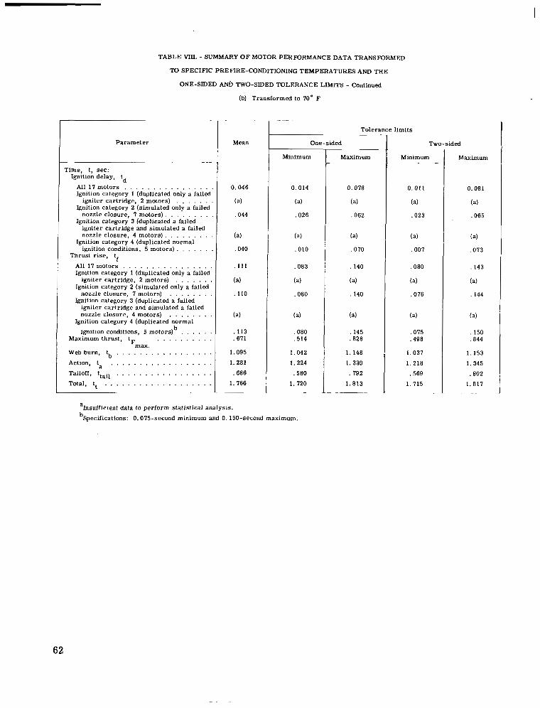
TABLE WII. - SUMMARY O F MOTOR PERFORMANCE DATA TRANSFORMED
TO SPECIFIC PREFIRE-CONDITIONING TEMPERATURES AND THE
ONE-SIDED ANi) TWO-SIDED TOLERANCE LIMITS - Continued
(b) Transformed to 70" F
P a r a m e t e r
Time, t , sec : - "
Ignition delay, td
All 17 m o t o r s . . . . . . . . . . . . . . . . Ignition c:ltegory 1 (duplicated only a failed
igni ter car t r idge, 2 motors ) . . . . . . . Ignition category 2 (simulated only a failed
nozz le c losure , 7 m o t o r s ) . . . . . . . . Ignition category 3 (duplicated a failed
igniter cartridge and simulated a failed nozz le c losure , 4 motors )
iwit ion condi t ions, 5 motors) . . . . . . . . . . . . . . . .
Ignition category 4 (duplicated normal
Thrus t r i s e , tf
All 17 m o t o r s . . . . . . . . . . . . . . . . Ignition category 1 (duplicated only a failed
igni ter car t r idge, 2 motors ) . . . . . . . Ignition category 2 (simulated only a failed
nozz le c losure , 7 motors) . . . . . . . . Ignition category 3 (duplicated a failed
nozz le c losure , 4 motors ) igni ter car t r idge and s imulated a failed
. . . . . . . . Ignition category 4 (duplicated normal
ignition conditions, 5 motors) b . . . . . . Maximum thrust , . . . . . . . . . .
tFmax . Web burn, L,, . . . . . . . . . . . . . . . . . Action, ta . . . . . . . . . . . . . . . . . . Tailoff, ttail . . . . . . . . . . . . . . . . . Total, t t . . . . . . . . . . . . . . . . . . .
"
Mean
0.046
(a)
,044
(a)
,040
,111
(a)
,110
(a)
.671
. 113
1.095
1.281
.686
1.766
Tole rance l imi t s t One-sided
Minimum
0.014
(a)
,026
(a)
, 010
.083
(a)
.080
(a)
,080 . 5 14
1.042
1.224
.580
1.720
ahsuf f ic ien t da ta to per form s ta t i s t ica l ana lys i s .
bSpecifications: 0.075-second minimum and 0.150-second maximum.
Maximum
0.078
(a)
,062
(a)
.070
. 140
(a)
. 140
(a)
.828 ,145
1.148
1.339
. 792
1.813 ~ ~"
I Two-sided
Minimum
0.011
(a)
,023
(a)
.007
,080
(a)
.076
(a)
.075
.498
1.037
1.218
,569
1.715
Maximum
0.081
(a)
,065
(a)
,073
,143
(a)
,144
(a)
,844 . 150
1.153
1. 345
,802
1.817 . "
62

TABLE VIII. - SUMMARY OF MOTOR PERFORMANCE DATA TRANSFORMED
TO SPECIFIC PREFIRE-CONDITIONING TEMPERATURES AND THE
ONE-SIDED AND TWO-SIDED TOLERANCE LIMITS - Continued
(b) Transformed to IO" F - Concluded
- -
Parameter
Chamber pressure, P, psia: Maximum, Pmax, . . . . . . . . . . . . . .
- Average web burn time, Ph . . . . . . . . . Average action time, Fa . . . . . . . . . . Average tailoff time, Tjtail . . . . . . . . . Average total time, Ft . . . . . . . . . . .
~ " -
Chamber pressure integral, JP dt, psia-sec: Web burn time, /a P dt . . . . . . . . . . . Action time, /t P dt . . . . . . . . . . . . Tailoff time, jt . P dt . . . . . . . . . . . Total time, A P d t
a
tail . . . . . . . . . . . . .
t ~ ~"
iesultant thrust, F, lbf: Maximum, Fmax. . . . . . . . . . . . . . . Average web burn time ', . . . . . . . . Average action time, Average tailoff time, - Ftail . . . . . . . . . Average total time, Ft . . . . . . . . . . .
b . . . . . . . . . . .
~.
tesultant impulse, I, lb -sec: f Web burn time, 6 . . . . . . . . . . . . . . Action timed, Ia . . . . . . . . . . . . . . . Tailoff time, I . . . . . . . . . . . . . . . Total time, It
tail . . . . . . . . . . . . . . . .
tesultant average propellant specific isp, Ibf-sec/lb :
Web burn time, I m- - sp,b ' ' ' . ' '
Action time, I sp,a . . . . . . .
Tailoff time, isp, tail . . . . . . Total time, isD. . . . . . . . .
impulse,
. . . . . .
. . . . . .
. . . . . .
. . . . . . 4vgage characteristic exhaust velocity,
C*, ft/sec (based on total time, tt) . . . . . .
(based on web burn time, t,,) . . . . . . . . iverage burning rate, Fb, in/sec
- ~ . _ _ _ _ _ ~
-~
Mean
1391
1329
1200
133
875
1455
1537
9 1
1545
33 468
31 660
28 525
3049
20 803 "~ ~ ~
34 655
36 541
2090
36 134
180.0
119.3
169.2
119.3
4608
0.914
Tolerance limits
Minimum
. .
- ~.
One-sided "
1335
1213
1153
86
835 " .
1393
1484
59
1494
31 869
30 353
27 295
1841
19 994
33 814
35 185
1250
35 971
176.2
115. I 154. I 115. I
4443
0.870 _ _ ~ -
Maximum
1460
1385
1241
180
915 ~
1516
1590
123
1597
. . "
35 066
32 967
29 155
4252
21 611 ~ ~-
35 496
37 298
2929
31 498
182.2
182.9
183.7
182.9 "
4181
0.958
Two-sided
Minimum ~____
1328
1261
1148
8 1
831 ~~ .~
1387
1419
56
1488
~
31 711
30 223
21 113
1721
19 914 ~~
33 131
35 I10 1161
35 895 "___
174.4
115. 3
153.3
175.3 ~
4426 -
0.865
Maximum
1466
1390
1251
184
919
1523
1596
126
1602
35 224
33 091
29 877
4311
21 691
35 579
37 313
3013
37 574
182.6
183.3
185.2
183.3
4 I98
0.962
'Specifications: 29 400-lbf minimum and 33 900-lbf maximum. dSpecifications: 35 800-lb -sec minimum and 37 600-lb -sec maximum. f f
63
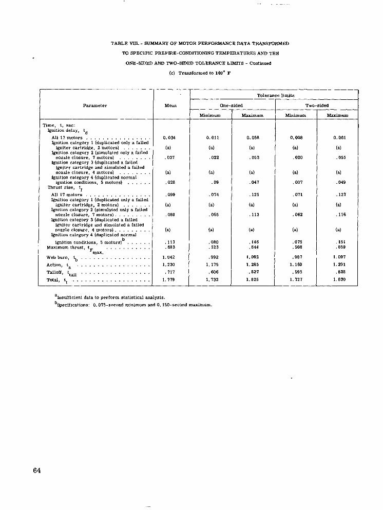
TABLE VIJI. - SUMMARY OF MOTOR PERFORMANCE DATA TRANSFORMED
TO SPECIFIC PREFIRE-CONDITIONING TEMPERATURES AND THE
ONE-SIDED AND TWO-SIDED TOLERANCE LIMITS - Continued
(c) Transformed to 140" F
T Parameter I
Time, t, sec: Ignition delay, td
All 17 motors . . . . . . . . . . . . . . . . Ignition category 1 (duplicated only a failed
igniter cartridge, 2 motors) . . . . . . . Ignition category 2 (simulated only a failed
nozzle closure, 7 motors) . . . . . . . . Ignition category 3 (duplicated a failed
igniter cartridge and simulated a failed nozzle closure, 4 motors)
ignition conditions, 5 motors) . . . . . . . . . . . . . .
Ignition category 4 (duplicated normal
Thrust rise, tf All 17 motors . . . . . . . . . . . . . . . . Ignition category 1 (duplicated only a failed
igniter cartridge, 2 motors) . . . . . . . Ignition category 2 (simulated only a failed
Ignition category 3 (duplicated a failed nozzle closure, 7 motors).
igniter cartridge and simulated a failed nozzle closure, 4 motors).
ignition conditions, 5 motors)
. . . . . . . .
. . . . . . . . Ignition category 4 (duplicated normal
b . . . . . . Maximum thrust, t . . . . . . . . . . .
Fmax. Web burn, t,, . . . . . . . . . . . . . . . . . Action, ta . . . . . . . . . . . . . . . . . . Tailoff, ttdl . . . . . . . . . . . . . . . . . Total, t, . . . . . . . . . . . . . . . . . . .
Mean
0.034
(a)
.037
(a)
.028
.099
(a)
,089
(a)
.113
.683
1.042
1.230 .717
1.779
T Tolerance
One-sided
Minimum
0.011
(a)
.022
( 4
.09
.074
(a)
.065
(a)
.080
.523
.992 1.175
.606
1.732
Maximum
0.058
(a)
.053
(a)
.047
.125
(a)
.113
(a)
.146
.844
1.092 1.285
.827
1.825
? limits
Two-sided
Minimum
0.008
(a)
.020
(a)
.007
. o n
(a)
.062
(a)
.075
.508
.987
1.169 .595
1.127
Maximum
0.061
(a)
.055
(a)
.049
,127
(a)
.116
( 4
. I51
.e59
1.097 1.291 .838 1.830
ahsufficient data to perform statistical analysis. bSpecifications: 0.075-second minimum and 0.150-second maximum.
64
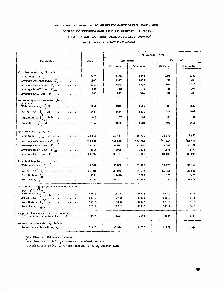
TABLE MI. - SUMMARY OF MOTOR PERFORMANCE DATA TRANSFORMED
TO SPECIFIC PREFIRE-CONDITIONIN6 TEMPERATURES AND THE
ONE-SIDEI) AND TWO-SIDED TOLERANCE LIMITS- Concluded
(c) Transformed to 140" F - Concluded
P a r a m e t e r
Chamber p ressure , P, psia:
"~ -
Maximumc, Pmax. . . . . . . . . . . . . . Average web burn t ime, P, . . . . . . . . -
u Average action t ime,
- Pa . . . . . . . . .
Average tailoff time, Ptail . . . . . . . . - -
Average total t ime, Pt . . . . . . . . . . ____ - .. - . "
Chamber p ressure in tegra l , {P dt ,
Web burn time, P dt ps ia -sec :
Action time, jt P dt . . . . . . . . . . . . . . . . . . . . .
'b
1
Tailoff time, Jt . P dt . . . . . . . . . . Total t ime, jt P d t
tail . . . . . . . . . . . .
t
Resultant thrust , F, Ibf: ~- .
Maximum, . . . . . . . . . . . . . Fmax. Average web burn timed, Tb . . . . . . . Average action t ime, F Average tailoff time, P . Average total time, Ft
- . . . . . . . . . . . . . . . . . . - tal l
. . . . . . . . . .
Resultant impulse, I, Ib -sec:
Web burn time, I,,
Action timee, Ia . . . . . . . . . . . . . . Tailoff time, Itail . . . . . . . . . . . . . Total t ime, It . . . . . . . . . . . . . . .
Resultant average propellant specific impulse, Isp, Ibf-sec/lb :
Web burn t ime, Isp, . . . . . . . . . . . Action time, is,, a . . . . . . . . . . . . . Tailoff time, . . . . . . . . . . . Total time,
f . . . . . . . . . . . . .
"
m -
- i s p , tail
I S D . t . . . . . . . . . . . . .
Average characterist ic exhaust velocity, C*, f t /sec (based on total t ime, t ) . . . .
t
Average burning rate, Fb, in / sec
(based on web burn time, b) . . . . . . . __
~-
Mean
1466
1396
1259
144
883
1454
1548
103
1557
. ." ..
35 114
'33 251
29 920
3315
20 997
34 649
36 791
2374
37 022 "
181. 2
180.9
176.6
180.9
4635
0.960
0 - Minimum
-
1400
1337
1209
93
843 .
1392
1494
67
1505
-
33 437
'31 878
28 631
2008
20 181 __.- -
33 808
36 029
1420
36 252
177.4
177.2
162.0
177 2 -___._
4471 -
0.914
ded
Maximum -
1532
1455
1308
195
9 24 " ..
1516
1601
140
1610
~- .___
36 791
'34 624
31 210
4622
21 813 ~- .
35 490
37 553
3327
37 792
184.8
184.5
191.2
184.5 "
4799
1.006
Two-sided
Minimum
1394
1331
1205
88
839 "
1386
1489
63
1500
"~ ~
33 271
'31 742
28 502
1878
20 100 -~
33 725
35 954
1325
36 176
177.0
176.9
160. 5
176.9
4455
0.909 ___ -__
-~
Maximum
1539
1460
1313
200
928
1522
1606
143
1615
36 957
'34 760
31 338
4752
21 894
35 573
37 629
3422
37 868 .~ ~
185.4
184.9
192. 7
184.9
4815
1.010 -
'Specification: 1700-psia maximum.
dSpecifications: 31 200-lb minimum and 36 000-lb maximum.
eSpecifications: 35 900-lb -sec minimum and 37 700-lb -sec maximum. f f f f
65
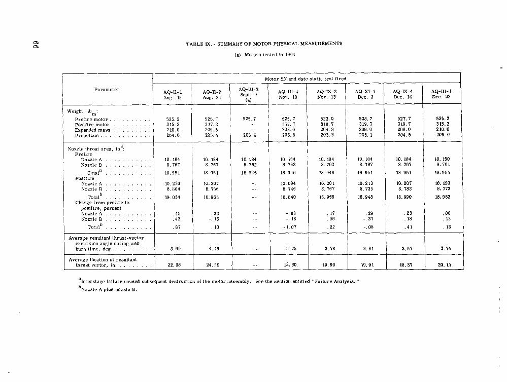
TABLE M. - SUMMARY O F MOTOR PHYSICAL MEASUREMENTS
(a) Motors tested in 1964
I - Parameter
Weight, lb,:
Prefire motor . . . . . . . . . . Postfire motor . . . . . . . . . Expended mass . . . . . . . . . Propellant . . . . . . . . . . . .
Nozzle throat area, in : 2
Prefire Nozzle A . . . . . . . . . . . Nozzle B . . . . . . . . . . .
Totalb . . . . . . . . . . .
Nozzle A . . . . . . . . . . . Nozzle B . . . . . . . . . . .
Postfire
b
Change from prefire to postfire, percent Nozzle A . . . . . . . . . . . Nozzle B . . . . . . . . . . .
Totalb . . . . . . . . . . .
. . . . . . . . . . . Total
Motor SN and date static test fired
AQ-XI- 1 Dec. 3
AQ-M-4 Dec. 14
AQ-111-1 Dec. 22
AQ-111-2 Sept. 9
(a)
AQ-111-4 Nov. 10
AQ-11-2 Aug. 31
AQ-X-2 Nov. 13
AQ-11- 1 Aug. 18
526.7 3 11.2 209. 5 205.4
525.2
210.0 315.2
205.6
525.2 315.2 210.0 204.0
525. I
"
3 17. 7 "
525. 7
208. o 205.6 206. a
10.184 10. 184 8.762 a. 762
18.946
10.094 "
18.946
" a . 746 " 18. a40
" -. 88 .. -. la " - 1.07
" 3. 75
" 18. 60.
523.0
204. 3 203. 3
3 18.7 528.7
209.0 319.7
205. 1
527.7
208.0 319. 7
204.5
10. 184 a. 161
18.951
10.230 8. a04
19.034
10. 184 a. 167
18.95 1
a. 756 10.207
18.963
10. 184 8.767
18.951
10.2 13 a. 735
18.948
10. 184 8.767
18.951
10.207 a. 783
18.990
10. 190 8.761
18.951
10. 190 8. 772
18.962
. 00
. 13
. 13
.45
.42
. a7
.23 -. 13
. 10
. 17
.06
.22
. 2 3
. 18
' 41
.29 -. 37
-. 08
Average resultant thrust-vector excursion angle during web burn time, deg . . . . . . . . .
thrust vector, in. . . . . . . . .
3.61 3.57 3.74 3. 99
22.38
4. 19
24.50
3. 78
19.90 19.91 20.11 18.37
alnterstage failure caused subsequent destruction of the motor assembly. See the section entitled "Failure Analysis. "
bNozzle A plus nozzle B.
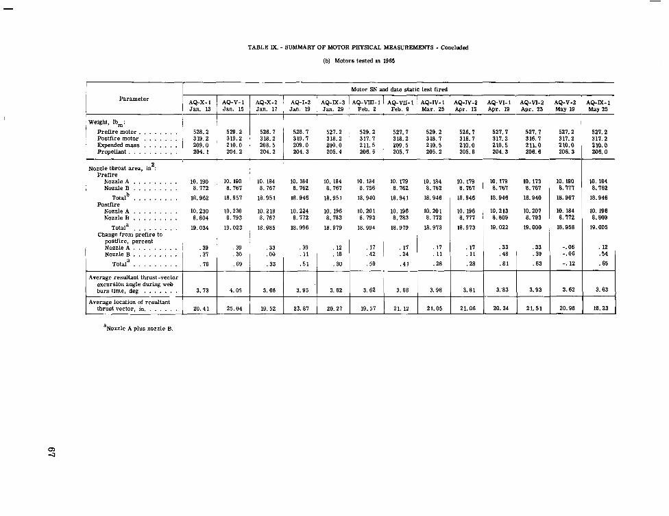
Parameter
Weight, lb,:
i Prel i re motor . . . . . . . . ~ Postfire motor . . . . . . . ' Expended mass . . . . . . .
Propellant . . . . . . . . . . Nozzle throat area, in : 2
Pref i re Nozzle A . . . . . . . . .
; Nozzle B . . . , . . . . . Totalb . . . . . . . . .
Nozzle A . . . , . . . . . Nozzle B . . . . . . . . .
Totala . . . . . . . . .
Postfire
Change from prefire to
TABLE M. - SUMMARY OF MOTOR PHYSICAL MEASUREMENTS - Concluded
(b) Motors tested in 1965
I 528.2 529.2
209.0 ' 210.0 319.2 319.2
204. 1 204.2
Motor SN and date static test fired ' AQ-E-3 IAQ"IIAQ"-1 AQ-IV-1 AQ-IV-2 AQ-VI-1 ' AQ-VI-2 AQ-V-2 AQ-M-1 I" "
Jan. 17 Jan. 19 1 Jan. 29 ' Feb. 2 Feb. 9 Mar. 25 Apr. 13 Apr. 19 Apr. 23 May 19 May 25 ~"i"""---"
1 526.7 528.7 527.2 , 529.2 527. I 529.2 526.7 527.7 527.7 527.2
208.5 209.0 209.0 211.5 209.5 210.5 210.0 210.5 211.0 210.0 318.2 319.7 318.2 ' 317.7 318.2 318.7 316.7 317.2 316.7 317.2
204.2 204.3 205.4 206.5 ' 205.1 205.2 205.8 204.3 206.6 206.3
10. 190 , 10. 190 ' 10. 184 10. 184 10. 184 10. 184 8.772 8.767 8.767 8.762 8.767 8.756
18.962 18.957 18.951 18.946 18.951 18.940
10. 230 10.230 10.218 10.224 10. 196 10.201 8.804 8.793 8.767 8.772 8.783 8. 793
19.034 19.023 18.985 18.996 18.979 18.994
.33 .39 . 12 .18 1 . 42
.30 .59 .33 Totala . . . , . . . . . .76 .69
. 17
i postfire, percent Nozzle A . . . , . . . . . Nozzle 0 . . . , . . . . .
Average resultant thrust-vector excursion angle during web burn time, deg . . . . . . . 3.62 3. 62 3.95 3.66 4.05 3.73
Average location of resultant thrust vector, in. . . . . . . 19. 57 20.27 23.87 19. 52 25.04 20.41 c
10. 179 10. 184 10. 179 10.179 10.173 ' 10. 190 8.762 8.762 8.767 1 8.767 8.767 I 6.777
18.941 18.946
10. 196 10.201 8.783 8.772
18.979 18.973
::: ' . l l . 17
. 4 1 . 2 8
3.68 3.98
21. 12 2 1.05
18.946
18.958 ' 19.000 19.022 18.973
8.772 8.809 8.793 8.777 10. 184 10.213 10.207 10. 196
18.967 18.946 18.940
. 17 . 11 .33 .48
.33
-. 12 . 6 3 . 8 1 .28
-. 06 .30 -. 06
3.81 3.62 3.93 3.33
21.06 20.98 21.51 20.34
527.2 317.2 210.0 206.0
i- 10.184 8.762
16.946
10. 196 8.809
19.005
18.23
aNozzle A plus nozzle B.
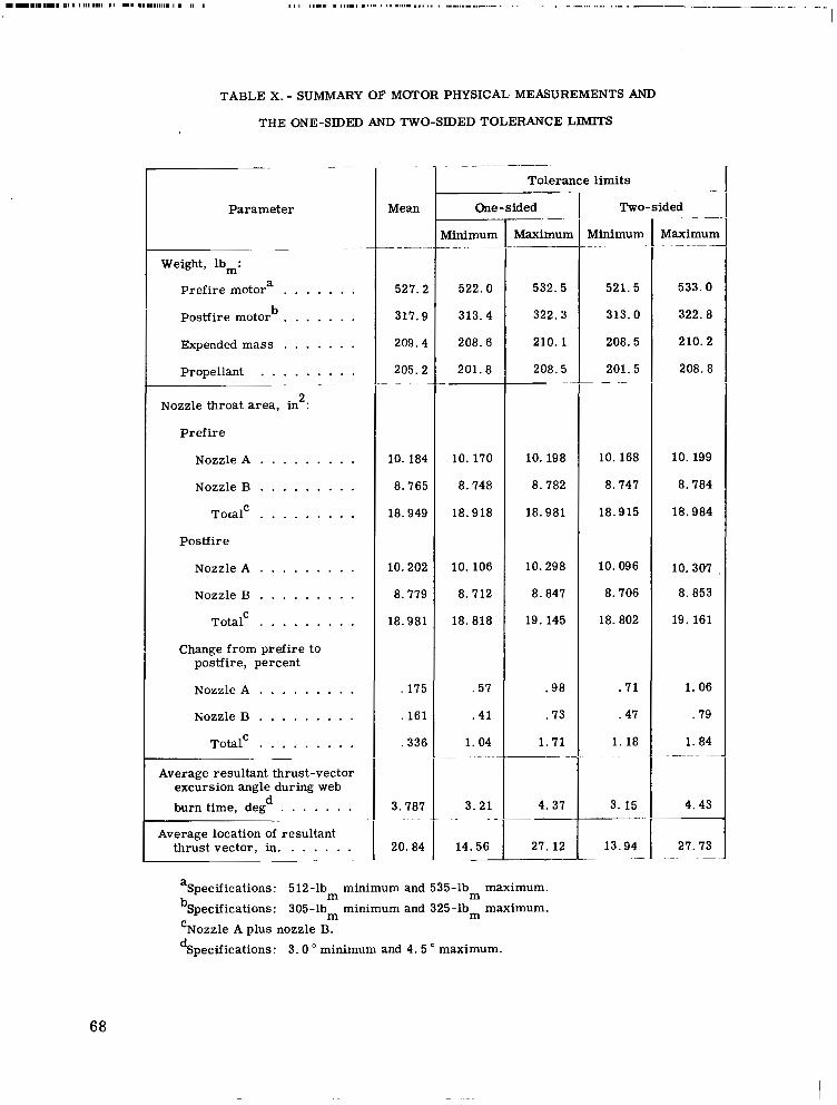
.................................................. ..-..-. ........................ -. .
TABLE X. - SUMMARY OF MOTOR PHYSICAL MEASUREMENTS AND
THE ONE-SIDED AND TWO-SIDED TOLERANCE LIMITS
-- ~ __
Parameter
"-
Weight, lb,:
Prefire motor
Postfire motor
Expended mass . . . . . . . Propellant . . . . . . . . .
a . . . . . . . b . . . . . . .
. . .
Nozzle throat area, in : 2
Pref i re
Nozzle A . . . . . . . . . Nozzle B . . . . . . . . .
T o d C . . . . . . . . . Postfire
Nozzle A . . . . . . . . . Nozzle B . . . . . . . . .
T o t a t . . . . . . . . . Change from prefire to
postfire, percent
Nozzle A . . . . . . . . . Nozzle B . . . . . . . . .
Total' . . . . . . . . . Average resultant thrust-vector
excursion angle during web burn time, deg d . . . . . . .
Average location of resultant thrust vector, in. . . . . . .
Mean
""
527.2
317.9
209.4
205.2 ... - .
10.184
8.765
18.949
10.202
8.779
18.981
,175
.161
.336
3.787
20.84
-
Tolerance limits
One-sided
VIinimum - " - "
522.0
313.4
208.6
201.8
10.170
8.748
18.918
10.106
8.712
18.818
.57
.41
1.04 - "-
3.21 .. "
14.56 "
Maximun
532.5
322.3
210.1
208.5 ~
10. 198
8.782
18.981
10.298
8.847
19. 145
.98
.73
1.71 "- -
4.37 "
27.12
-
Two-sided
Minimum " ..
521.5
313.0
208.5
201.5 - - "
10.168
8.747
18.915
10.096
8.706
18.802
. 7 1
.47
1. 18 ~ ~ ."
3. 15
13.94 ~ _-
"
Maximum ~ ___
533.0
322.8
210.2
208.8
10.199
8.784
18.984
10.307
8.853
19. 161
1. 06
.79
1.84 ~-
4.43
27.73 ". . -
I
aSpecifications: 512-lb minimum and 535-1b maximum. bSpecifications: 305-lb minimum and 325-lbm maximum. 'Nozzle A plus nozzle B. dSpecifications: 3 .0 ' minimum and 4.5 a maximum.
m m m
68
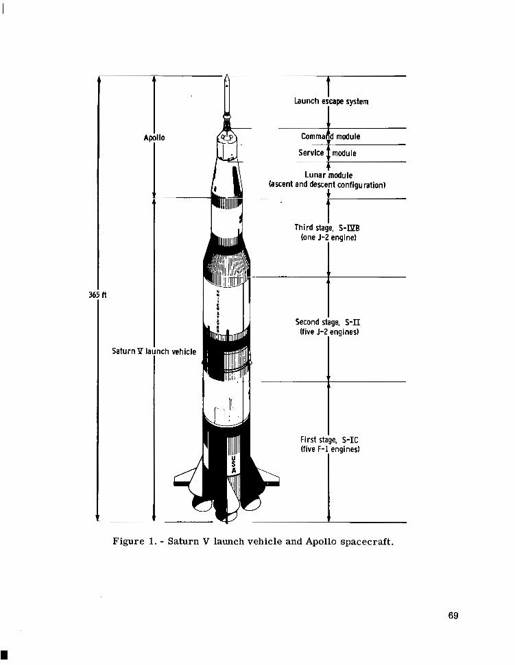
n
Saturn Y la
Launch escape system
lo
lunar module (ascent and descent configuration)
t Third staie, S-IPB
(one J-Z engine)
1 I Second stage, S-II
First stige, S-IC (five F-1, engines)
Figure 1. - Saturn V launch vehicle and Apollo spacecraft.
69
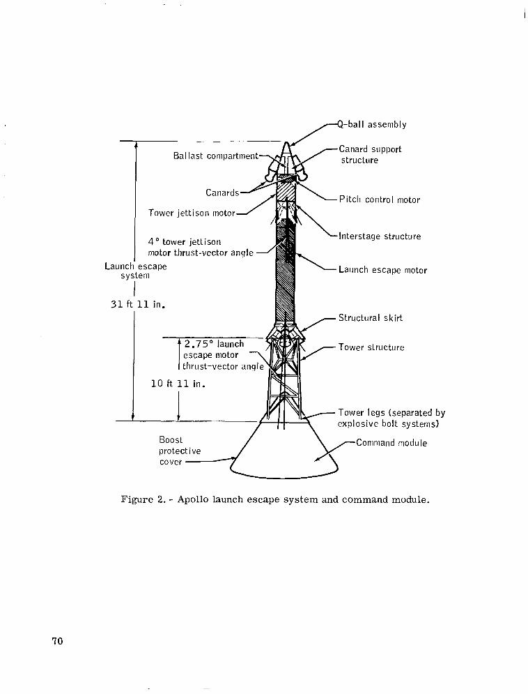
p - b a l I assembly ~ ""
t .. ___"
Ballast compartment Canard support structure
Launch escape motor
t psr;lnp mntnr 7
I ----r- *.'---. 1 thrust-vector angle\
\Pitch control motor
S \Interstage structure
Structural skirt
Tower legs (separated by explosive bolt systems)
Boost Command module protective cover
Figure 2. - Apollo launch escape system and command module.
70

55.6 in.
(a) Schematic.
Loaded motor case Solid propellant
(b) Pictorial view.
Figure 3. - The tower jettison motor for the Apollo launch escape system.
71
( c ) Photograph.
Figure 3 . - Concluded.
72
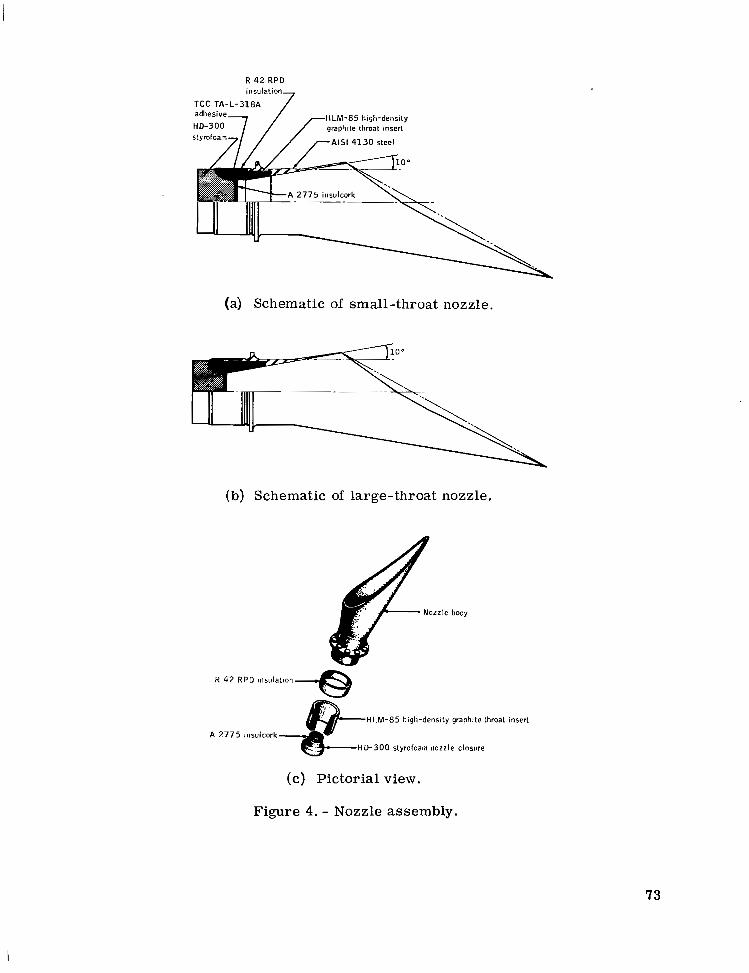
R 42 RPD
HLM-85 high-density graplltte throat Insert
AIS1 4130 steel
2775 insulcork
(a) Schematic of small-throat nozzle.
(b) Schematic of large-throat nozzle.
(c) Pictorial view.
Figure 4. - Nozzle assembly.
73
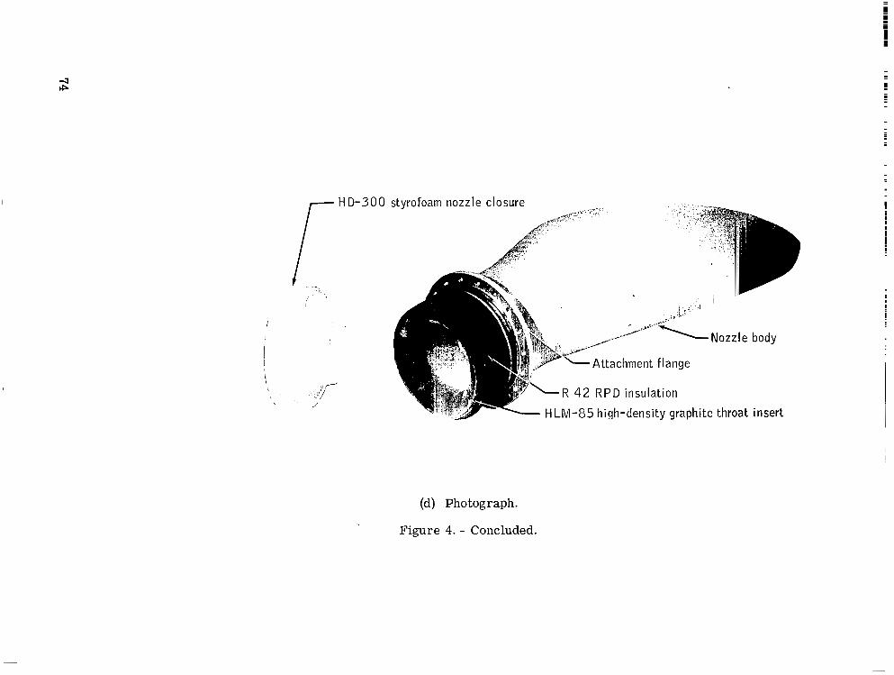
.
I H D - 3 0 0
i
stvrofoam nozzle closure _ ,
,".* Nozzle body
~ " - \-Attachment flange
R 42 RPD insulat ion
HLM-85 high-density graphite throat insert
(d) Photograph.
Figure 4. - Concluded.
I
I
(a) Schematic. Figure 5. - Propellant grain.
(b) Photograph.
Figure 5. - Concluded.
76
1 111.1 1
-GT Gen Gard V-44 asbestos-filled
AIS1 4 steel nozzle
buna-N rubber external insulation
F MX-2625 silica phenolic internal insulation
AIS1 410 stainless steel pel1 container assembly (ref. figs.
8.069 in . J
(a) Schematic of the TE-381 igniter assembly.
/r Igniter cartridge port plugs
h AIS1 410 stainless steel pellet-container assembly
AIS1 4 igniter
Mi l -P-79-type PEG paper-base phenolic liner tube
TCC TP-E-8104 solid propellant
F MX-2625 silica phenolic internal insulation
AIS1 4130 steel
GT Gen Gard V-44 asbestos-filled buna-N rubber external insulation
130 steel case
(b) Pictorial view of the TE-381 igniter assembly.
Figure 6. - Motor ignition system.
77

I I I 11111 I I I I 1 1 1 111111111 I I1 I 1 I I
Apollo standard initiator
Body
Maln charge
(c) Schematic of pyrotechnic igniter cartridge.
=-End closure (347 C R E S )
lsomica flexible insulation -- (CI-20)
-Main charge Washer E-787 epoxy (50 mg of impregnated glass cloth -e SOS mix 108)
isomica flexible insulation (CI-20)
(65 mg of lgnlhon charge
SOS mlx 108) “Bridgewire (110 Nilstain wire)
Header (wlth 4 pins) AD94 ceramic coated with molybdenum-mang and nickel plated Kovar A wire
(17-4P CRES)
(d) Pictorial view of Apollo standard initiator. Load of main charge and ignition charge vary with lot.
Figure 6. - Continued.
78
AIS1 41 steel pe
AIS1 410 stainless steel pellet-container assembly 12 g of no. 2 A U .S. Flare
boron-potassium nitrate pellets
disk of 850 3M tape Sealed with a one-piece
Sealed with one piece of 473 3M tape
0.750 in. ___I (e) Schematic of igniter pellet container.
- Sealed with one piece of 473 3 M tape
of no. 2A U . S . F -potassium nitrate
- Sealed with a one-piece disk of 850 3 M tape
(f) Pictorial view of igniter pellet container.
Figure 6. - Concluded.
'tare pellets
79
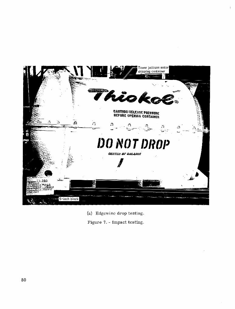
(a) Edgewise drop testing.
Figure -7. - Impact testing.
80
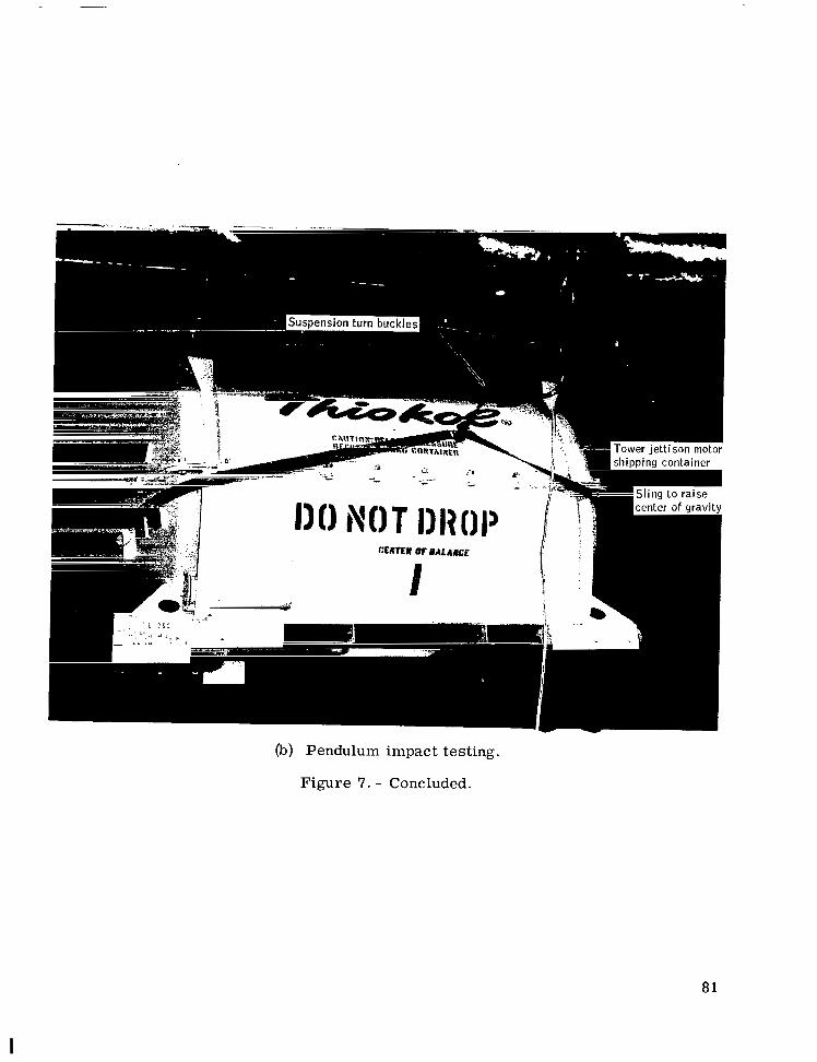
(b) Pendulum impact testing.
Figure 7. - Concluded.
81
I
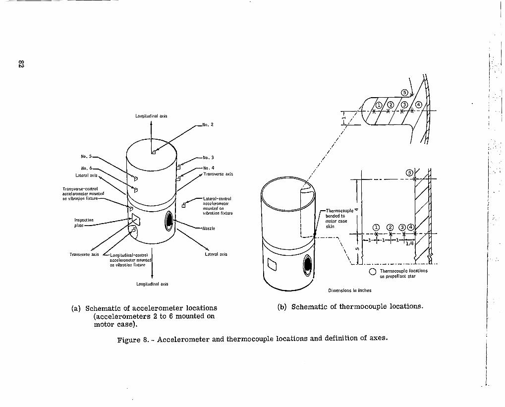
Lonyitudinal axis
Transverse-control I/ accelerometer mounted on vibration fixture Lateral-control
accelerometer mounted on vlbration fixture
h N o r z l e
Inspection plate
accelerometer mounted on vibration fixture I
Longitudinal axis
/
/ /'
" .__ "
0 Thermocouple locations on propellant star
W Dimensions ill inciles
(b) Schematic of thermocouple locations.
Figure 8. - Accelerometer and thermocouple locations and definition of axes.

t Longitudinal axis vibration input
(a) Schematic of longitudinal vibration test fixture.
I r Forward skirt on motor case
(b) Schematic of lateral vibration test fixture.
Figure 9. - Vibration test fixtures.
83
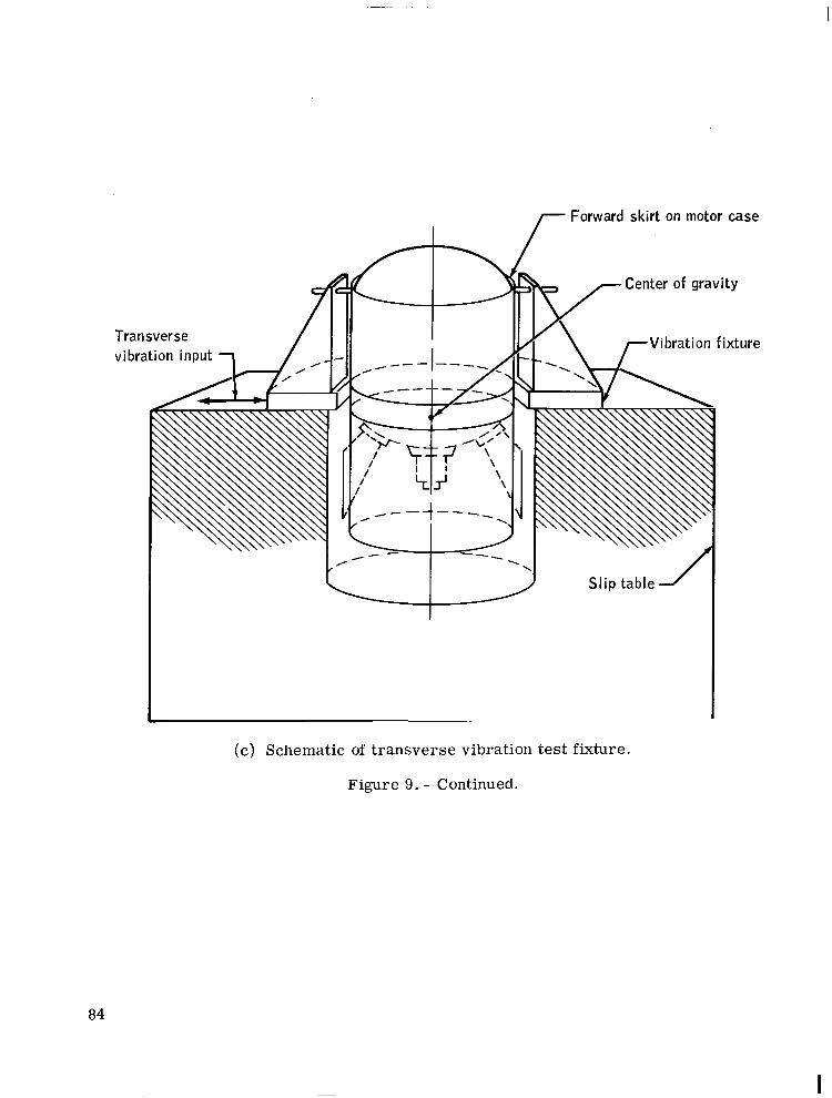
7 Forward skirt on motor case
- Sl ip table 1
(c) Schematic of transverse vibration test fixture.
Figure 9. - Continued.
84
I
(d) Photograph of longitudinal vibration test fixture with temperature-conditioning unit.
Figure 9. - Continued.
85
(e) Cornerwise drop testing.
Figure 9. - Concluded.
86
Double-flexure-mounted aft side load cell ouble-flexure-mounted
T E - 3 8 0 interstage structure TE-380 sol id-propellant
(a) Schematic of top view.
Longitudinal-thrust-calibration hydraulic actuator r T E - 3 8 0 solid- TE-380 solid-propellant
Double-flexure- mounted forward
(c) Schematic of end view.
(d) Photograph, end view.
Figure 10. - Continued.
88
I

(e) Photograph, side view.
Figure 10. - Concluded.
89
I
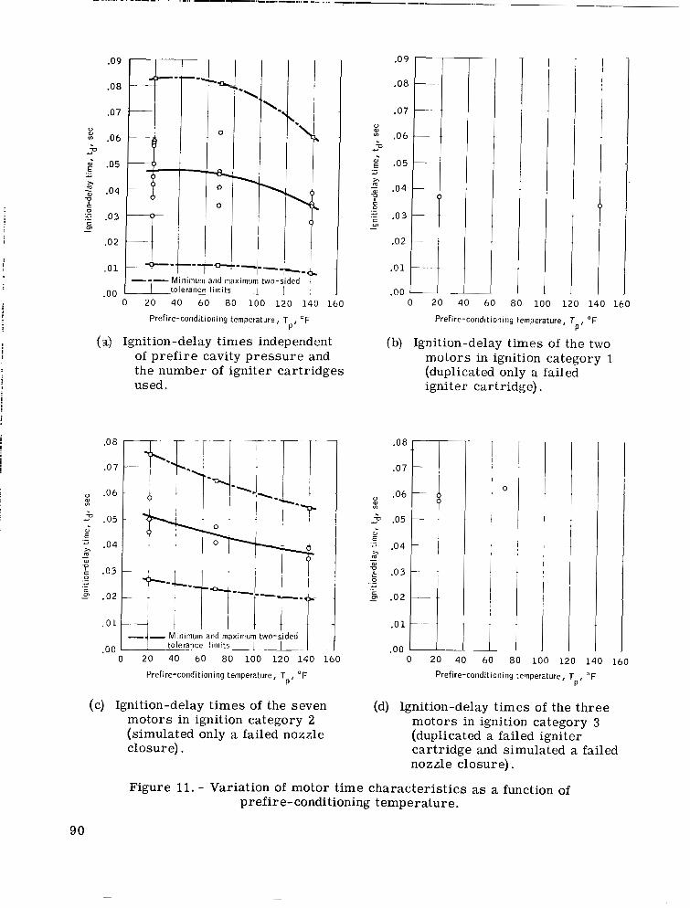
I
.09
.O 8
.O 7 0
.06 Y U
.- E" .05
5 .04
t 2 .03
Y
U
S P, -
.02
. 0 1
on .. . 0 20 40 60 80 100 120 140 160
Prefire-conditioning temperature, T "F P'
(2) Ignition-delay times independent of prefire cavity pressure and the number of igniter cartridges used.
.O 8
.o 7
.Ob W
.05
2 ._ ; .04
7 .03
m W -
.- 1
c E .02 ._
. 0 1
.oo j tolera?ce limits I I I - - Minimum and maximum two-sided
0 20 40 60 80 100 120 140 160
Prefire-conditioning temperature, T "F P '
(c) Ignition-delay times of the seven motors in ignition category 2 (simulated only a failed nozzle closure).
.o -O*t.i 1
.oo 0 20 4 0 60 80 100 120 140 160
Prefire-conditioning temperature, T O F
P'
(b) Ignition-delay times of the two motors in ignition category 1 (duplicated only a failed igniter cartridge).
.08
.07
.06 W In
2 .05
E .04
f .03
- >
._ d - El .02
.01
.oo 0 20 40
I I I
4 0
t
60 80
I
*
I
100 120 140 160 Prefire-conditioning temperature, T "F
P '
(d) Ignition-delay times of the three motors in ignition category 3 (duplicated a failed igniter cartridge and simulated a failed nozde closure).
Figure 11. - Variation of motor time characteristics as a function of prefire-conditioning temperature.
90

.20
.18
.16 I
.14
.12
. l o
.08
.06 I
.04 0 20 4 0 6 0 80 100 120 140 160
Prefire-conditioning temperature, T "F Prefire-conditioning temperature, T O F P ' P '
(e) Ignition-delay times of the five (f) Thrust-rise times independent of motors in ignition category 4 prefire cavity pressure and the (duplicated normal ignition number of igniter cartridges conditions). used.
.18
.16
L .14
0 W VI
u
z .12 E W VI - 2 .10
1 I- 2
.08
.06
1I 1 -
0 20 40 60 80 100 120 140 160
Prefire-conditioning temperature, T "F P'
(g) Thrust rise times of the two motors in ignition category 1 (dupli- cated only a failed igniter cartridge).
.20
.18
.16 u "l
u * .14 L
1 E .12 W "l - L
$ .10 2 1 +
.08
.06
.04 0 20 40 60 80 100 120 140 160
Prefire-conditioning temperature, T "F P '
(h) Thrust-rise times of the seven motors in ignition category 2 (simulated only a failed nosAe closure).
Figure 11. - Continued.
91
I
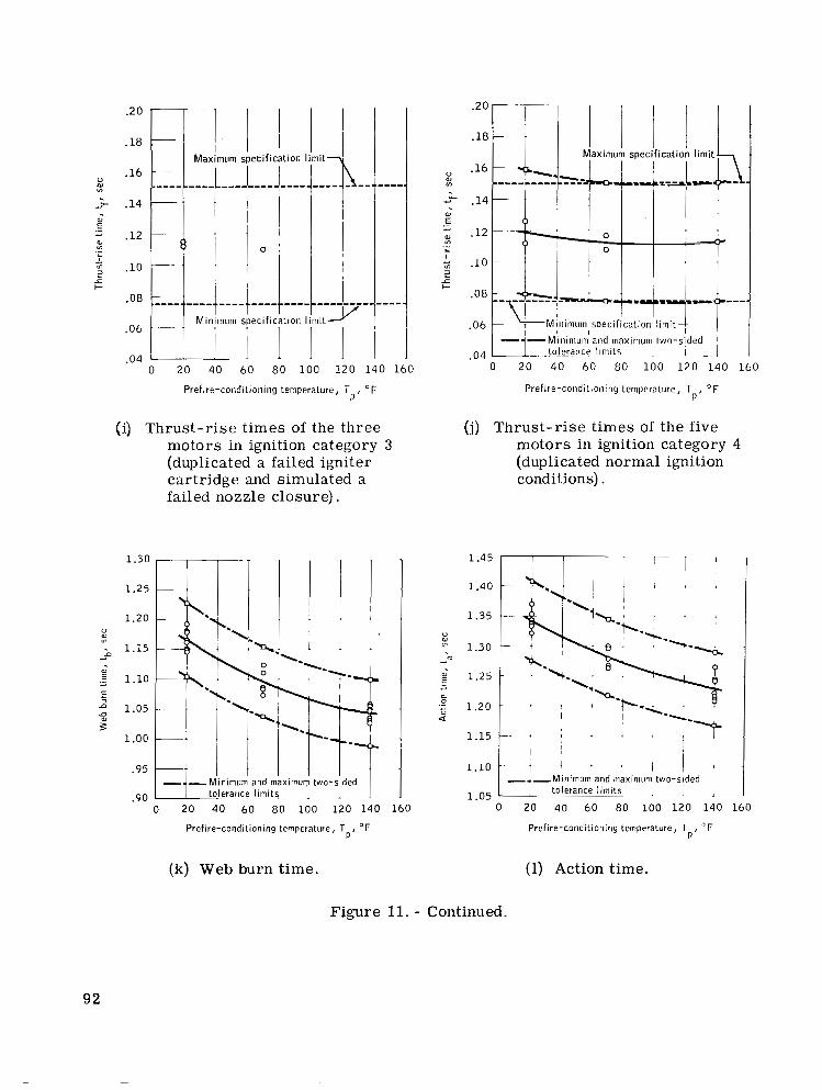
.2 0
.18 __
Mar .16 __ ~. ""_ ""_ .14 _ _ ~
.12 - -.
.10 -~
-08 K"."" Mi r
.06 -~ .
1 .
.04 0 20 40 60 80 100 120 140 160
Prefire-conditioning temperature, T O F P '
(i) Thrust-rise times of the three motors in ignition category 3 (duplicated a failed igniter cartridge and simulated a failed nozzle closure).
0 20 40 60 80 100 120 140 160
Prefire-conditioning temperature, T OF P I
(k) Web burn time.
.04 I 1 0 20 40 60 80 100 120 140 160
Prefire-conditioniny temperature, T O F P '
(j) Thrust-rise times of the five motors in ignition category 4 (duplicated normal ignition conditions).
1.45
1.40
1.35
" OJ
1.30 m
d
E 1.25 - d
c 9 1.20 4
1.15
1.10
1.05
- ,Minimum and maximum two-slded tolerance limits. , . 1
0 20 40 60 80 100 120 140 160
Prefire-conditloning temperature, T "F P'
(1) Action time.
Figure 11. - Continued.
92
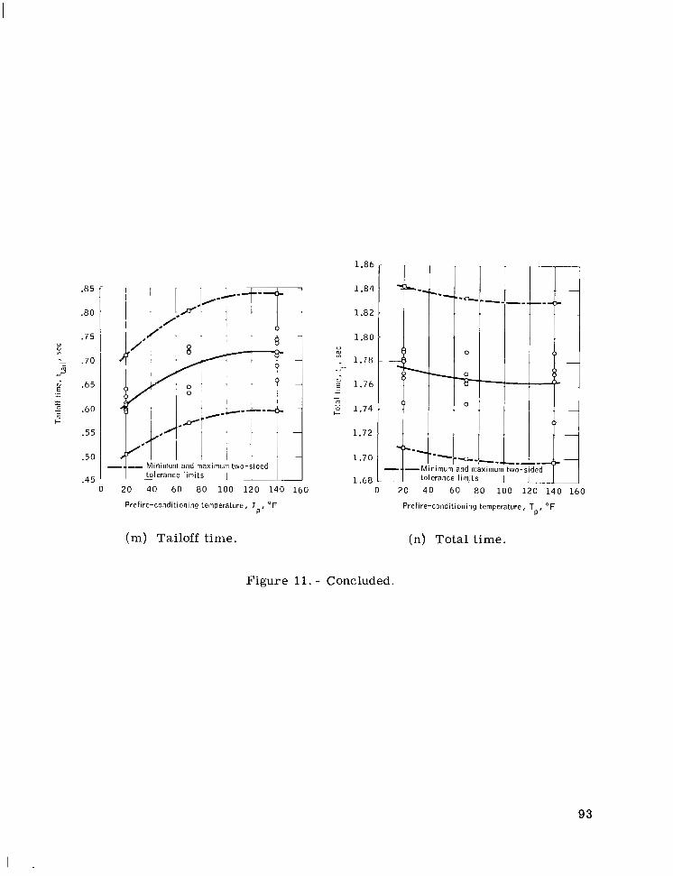
.85
.SO
.75 0 ar m
: .70 m d
+d 2 .65
g .60
._ - L
+.
m + .55
.50
.45 0 20 40 60 80 100 120 140 160
Prefire-conditioning temperature, To, "F
(m) Tailoff time.
1.86
1.84
1.82
1 .80 u %
~ 1.78 - 1.76 - -
- n 2 1.74
1.72
1.70
1.68
Prefire-conditioning temperature, T O F P I
(n) Total time.
Figure 11. - Concluded.
93
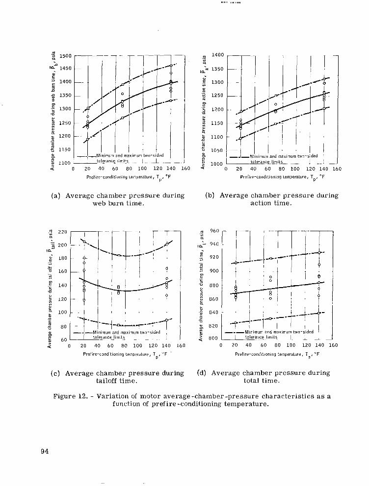
m .z 1500
1450 W
1400
a E
1350 3
5 1300 5 L 2 1250
?!
m
TJ
VI
a & 1200 n m fj 1150 W m I . ; 1100
L a 0 20 40 60 80 100 120 140 160
Prefire-conditioning temperature, T OF P '
(a) Average chamber pressure during web burn time.
.: 220
I nu
0
- 'Z 200
180 .- a .A- ..- 2 160 m
.E 140
.- u
m
73
120
a 100 &
2 80
m
f 60
VI W L
r)
E
W
> a 0 20 40 6 0 80 100 120 140 160
Prefire-conditioning temperature, T O F ' P '
(c) Average chamber pressure during tailoff time.
1400 .- u) n
In. 'm 1350
.E 1300 * E .- t; 1250 m
.- m
1200 -a W L 3 1150
B W
E m
a 2 1000
0 20 40 60 80 100 120 140 160
Prefire-conditioning temperature, T "F P '
(b) Average chamber pressure during action time.
m 960 ._ VI Q
940
W
.E 920
m
3 900 m
- d u
._ L
-u 880 L
2 860 B 5
u1
840 L: s
: g 820
< 800
0 20 40 60 80 100 120 140 160
Prefire-conditioning temperature, T "F P '
(d) Average chamber pressure during total time.
Figure 12. - Variation of motor average-chamber-pressure characteristics as a function of prefire-conditioning temperature.
94

0
1540 m In .- 2 1520 n
a U
wn 1500 2 1480 E .- a
1460 n 5 .- F 1440 L
V - 1420 $ .
c .- d
1400 L
In In g 1380 z n -c u 5 1360
0
(a)
0 W In
20 40 60 80 100 120 140 160 Prefire-conditioning temperature, T "F
P'
Chamber pressure integral during web burn time.
, 180 m
- 160
.- In L1
V
a a
1 140
-?- a; 120
b 100
E L
a .- - .- m 1
.- F 80
3 60
.- 4c
L
V
m a
5 In g 20
" .. ~". 1-+;I ". ~
-
tolerance limits Minimum and maximum two-sided
-c V 0 20 40 60 80 100 120 140 160
Prefire-conditioning temperature, T O F P'
(c) Chamber pressure integral during tailoff time.
d 1560
4 1540
.- a E
m m
1520 U - 6 1500 a .- 2 1480 In In
1460 z 5 1440 n
V 20 40 60 80 100 120 140 160 Prefire-conditioning temperature, T O F
P '
(b) Chamber pressure integral during action time.
0 W
.!? 1620 0.
1600
?4d 1580
Z 1560
a
E ._
a 1
F 1540 .- L
V
3 1520 m a
" 1500 E
g 1480
n z 5 1460
In In
x V 0
1 tolerance limits I I 20 40 60 80 100 120 140 160 Prefire-conditioning temperature, T OF
P'
(d) Chamber pressure integral during total time.
Figure 13. - Variation of motor chamber-pressure-integral characteristics as a function of prefire-conditioning temperature.
95
36 000
-. 35 000 .a L
IC g 34 000 .- a
2 33 000 .n
32 000 E L
U
.- 31 000
3 L
5 30 000
m - - : 29 000 01 m
f 28 000 - a 27 000
- - Mimimum and maximum two-sided tolelance limits 1 I 1
0 20 40 60 80 100 120 140 160
Prefire-conditioning temperature, Tp, F
(a) Average resultant thrust .during web burn time.
- ;; 5000 -
I C 'Z 4500
E" 4000 ._ L L
0 - '; 3500 - m c
V
VI
._ $ 3000 1
2500
{ 2000 VI E
1500
2 1000 Mimimum and maximum two-sided
0 20 40 60 80 100 120 140 160 Prefire-conditioning temperature, Tp, F
(c) Average resultant thrust during tailoff time.
33 000
e- 32 000 ILL-
I . 31 000
.- 4
5 30 000
g' 29 000 5 % 28 000 5
.- d
m
.- U
L
27 000 - d = VI
E 26 000
f 25 000
W m
24 000 1 tolerance limits wo-sided I
0 20 40 60 80 100 120 140 160
Prefire-conditioning temperature, Tp, F
(b) Average resultant thrust during action time.
22 500
- 22 000 0 - L
I Ld
.E 21 500
3 21 000
W - - m - 01 c 3
._ L
0 20500 u VI 3 L
5 20 000 d
m - - 2 19 500 E
5 19 000 a
18 500
al m
>
I I tolerance limits I 0 20 40 60 80 100 120 140 160
Prefire-conditioning temperature, T,, F
(d) Average resultant thrust during total time.
Figure 14. - Variation of motor average-resultant-thrust characteristics as a function of prefire-conditioning temperature.
96

36 500
36 000 el
- n
35 500 .- a
.a 0
g 35 000
34 500 = .- s B
.E 33 500
34 000 - = 0
d
- B 21 33000
32 500 CT
0 20 40 60 80 100 120 140 160
Prefire-conditioning tempeiature, Tp, O F
(a) Resultant impulse during web burn time.
~~
”
4-
0 0
-p c
“d””””
limurn and maximum two-sided erance limits 1 I
I
0 20 40 60 80 100 120 140 160
Prefire-conditioning temperature, Tp, O F
(c) Resultant impulse during tailoff time.
39 000
2 e 38 500 : 38 000
2 37500
m
0 al
m
a- __ .- d
p 37 000 .- L
m B 36 500 -
L 36 000
$ 35 500
E m d -
0:
35 ooa I 0 20 40 60 80 100 120 140 160
Prefire-conditioning temperature, T,, “F
(b) Resultant impulse during action time.
39 000
% 38 500 “
L- 38 000
0
- n
‘j 37 500 z - m d
0 0
37 000 m
._ 5
36-500 - 3
‘Z 36 OOC
$ 35 50C
35 ooc
P
- 5 a:
0 20 40 60 80 100 120 140 160
Prefire-conditioning temperature, Tp, O F
(d) Resultant impulse during total time.
Figure 15. - Variation of motor resultant-impulse characteristics as a function of prefire-conditioning temperature.
97
I
/--
Je /*-
Minimum and maximum two-sided tolerance limits
CT 172 L
0 20 40 60 80 100 120 140 160 Prefire-conditioning temperature, TpP F
(a) Resultant average propellant specific impulse during web burn time.
190
220
210
200
190
180
170
160
d
d - CT x 140 1 5 0 K 0 20 1
I I I 60 80 100 120 140 160
Minimum and maximum I
I two-sided tolerance limits
Prefire-conditioning temperature, Tp: F
(c) Resultant average propellant specific impulse during tailoff time.
Minimum and maximum two-sided tolerance limits
I . . .
60 80 100 120 140 160 PrPfire-conditioning temperature, Tp: F
(b) Resultant average propellant specific impulse during action time.
Minimum and maximum two-sided tolerance limits
0 20 40 60 80 100 120 140 160 Prefire-conditioning temperature, Tp: F
(d) Resultant average propellant specific impulse during total time.
Figure 16. - Variation of motor resultant-average-propellant-specific-impulse characteristics as a function of prefire-conditioning temperature.
98
510c
3 c 500C %
I V 2 490C
W
d .- 0 0 - 2 480C
$ 4700
.- G 4600 z
d
W 0 .-
.d U
4500 r 0 W
4400 W
P 4300
-
-
-
-
-
0 20 40 60 80 100 1 2 0 140 160
Prefire-conditioning temperature, T "F P '
Figure 17. - Variation of motor average characteristic exhaust velocity as a function of prefire-conditioning
I 1 " L A I
temperature.
1600
.: 1550 Cl
x 1500 ; a k 1450
g 1400
2 1350
2 1300 P
2 VI VI
L
LI
J=
.-
1250
1200 0
"
0 -
~
r ~ --- Maximum one-sided
- I - .1 2 , I
tolerance l imit
20 4 0 60 80 100 120 140 160
Prefire-conditioning temperature, T O F P'
Figure 19. - Variation of motor maxi- mum chamber pressure as a function of prefire-conditioning temperature.
v 1.15 VI \
1.10 I L -
E 1.05 .- d
2 1.00
c P
d w 0.90 2 .5 0.85 E
g, 0.80
' 0.75
0.95 .- L 3 P
JI
LI
;
.# "-
- I .I .. "-
I -m
and maximum d tolerance l imit!
0 20 40 60 80 100 120 140 160
Prefire-conditioning temperature, T O F P'
Figure 18. - Variation of motor average burning rate during web burn time as a function of prefire-conditioning temperature.
JI 4.20 W m
2 4.10 P c m
.- 6 4.00 Ln
3 0
L
2 3.90 b
? 3.80 d " d VI 3 L
5 3.70 d c m - d ; 3.60 E W
3.50 5 a
3.40
C
4
0
.6 3
0
/ /'
0
/ /'
18 19 20 21 22 23 24 25 26
Average location of resultant thrust vector, in.
Figure 20. - Variation of motor aver- age resultant thrust-vector excur- sion angle as a function of motor average location of resultant thrust vector.
99

I111 I I l l . . . . ... .
100
1800
1600
.- m 1400 u, Q
a - 1200 $ 1000 3 ln ln
800 B 2 600
"0 400
L
m E
200
0
(a) Chamber pressure.
40 O o 0 I I I 35 000
f 30 000 ce
U - 25 000 v)
g 20 000
- U 2 15 000 U
v) 3
E 10 000
5 000
0 .3 .6 .9 1.2 1.5
Motor operating time, t, sec
(b) Resultant thrust.
Figure 21. - Nominal motor performance as a function of operating time and the calculated statistical limits (two-sided tolerance limits) at 20" F.
1600 I 1800 I .2 1400
a - 1200 2 1000
800
2 600
v 400
200
u) II
. 3 Y, Y,
g s x
0 .2 .4 .6 .8 1.0 1.2 1.4
Motor operating time, t , sec
( a ) Chamber pressure.
40 000 - 35 000
- 30 000 2 25 000 5 20 000
- 3 15 000
- n LL
3 L
U c
3 ul
E aJ 10 000
5 000
0 .2 .4 .6 .8 1.0 1.2 1.4
Motor operating time, t , sec
(b) Resultant thrust.
Figure 22. - Nominal motor performance as a func- tion of operating time and the calculated statistical limits (two-sided tolerance limits) at 70' F.
101
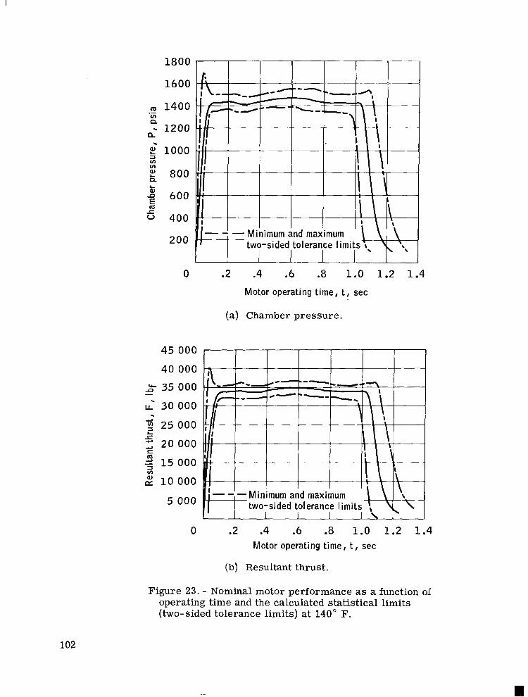
1800
1600
1400
- 1200 .- v) n
n
d 3 i o o o v) VI
2 800
5 600
0 400
200
n
2
0
45 000
40 000 _9’ 35 000 -
30 000
g 25 000 . 4
r, 20 000 L
.U
cll S
v) 3 2 15 000
L$ 10 000
5 000
1 I 1 1
I I
I -I
1 I
” - Minimum and maximum two-sided tolerance l imit
.2 .4 .6 .8 1.0 1.2 1.4 Motor operating time, t, sec
(a) Chamber pressure.
0 .2 .4 .6 .8 1.0 1.2 1.4 Motor operating time, t , sec
(b) Resultant thrust.
Figure 23. - Nominal motor performance as a function of operating time and the calculated statistical limits (two-sided tolerance limits) at 140” F.
102
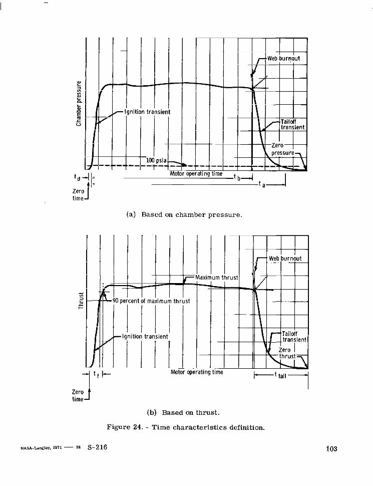
c VI =I L c c
c
nitic
I I
4" 1 1 I I I I
transient
~~
(a) Based on chamber pressure.
Ixi
1s
1 1 c I m
1 1
I I
ieni
1
Zerof time
(b) Based on thrust.
Figure 24. - Time characteristics definition.
103
NATIONAL AERO"%biCS' AND SPACE ADMINISTRA'IION WASHINGTON, D. C. 20546
OFFICIAL BUSINESS PENALTY FOR PRIVATE USE 5300
FIRST CLASS MAIL
NATIONAL AERONAUTICS ANI POSTAGE AND FEES PAID
SPACE ADMINISTRATION
0 9 U 0 0 1 53 51 305 71.10 00943 A I R FORCE WEAPONS LABORATORY /WLOL/ K I R T L A N D AFB, NEW M E X I C O 87117
A J T E - L O U BOWMAN, CHIEF,TECH* L I B R A R Y
If Undeliverable (Section 158 Postal Manual) Do Not Return
" T h e aeronautical and space activities of the Unitea Stntes shall be conducted so as to contribute . . . t o t he expansiogz of human knowl- edge of phenomena i n the atntosphere and space. The Adminis t ra t ion shall provide for the widest practicable and appropriate dissemination of information concerning its activities and the resdts thereof!'
-NATIONAL AERONAUTICS AND SPACE ACT OF 1958
NASA SCIENTIFIC A N D TECHNICAL PUBLICATIONS
TECHNICAL REPORTS: Scientific and technical information considered important, complete, and a lasting contribution to existing knowledge.
TECHNICAL NOTES: Information less broad in scope but nevertheless of importance as a contribution to existing knowledge.
TECHNICAL MEMORANDUMS: Information receiving limited distribution because of preliminary data, security classifica- tion, or other reasons.
TECHNICAL TRANSLATIONS:' Information published in a foreign language considered to merit NASA distribution in English.
SPECIAL PUBLICATIONS: Information derived from or of value to NASA activities. Publications include conference proceedings, monographs, data compilations, handbooks, sourcebooks, and special bibliographies.
TECHNOLOGY UTILIZATION PUBLICATIONS: Information on technology used by NASA that may be of particular
CONTRACTOR REPORTS: Scientific and technical information generated under a NASA Technology Utilization R~~~~~~ and contract or grant and considered an important ccintribution to existing knowledge.
interest in commercial and other non-aerospace applications. Publications include Tech Briefs,
Technology Surveys.
Details on the availability of these publications may be obtained from:
SCIENTIFIC AND TECHNICAL INFORMATION OFFICE
. .
. . . ' NATIONAL AERONAUTICS AND SPACE ADMINISTRATION. . . Washington, D.C. PO546 / . _ , ; , ,; '::.
8 ,
, . c . .