QoS: RSVP Configuration Guide, Cisco IOS XE Release 3S · CHAPTER 8 PfRRSVPControl123...
156
QoS: RSVP Configuration Guide, Cisco IOS XE Release 3S Americas Headquarters Cisco Systems, Inc. 170 West Tasman Drive San Jose, CA 95134-1706 USA http://www.cisco.com Tel: 408 526-4000 800 553-NETS (6387) Fax: 408 527-0883
Transcript of QoS: RSVP Configuration Guide, Cisco IOS XE Release 3S · CHAPTER 8 PfRRSVPControl123...

QoS: RSVP Configuration Guide, Cisco IOS XE Release 3S
Americas HeadquartersCisco Systems, Inc.170 West Tasman DriveSan Jose, CA 95134-1706USAhttp://www.cisco.comTel: 408 526-4000 800 553-NETS (6387)Fax: 408 527-0883
THE SPECIFICATIONS AND INFORMATION REGARDING THE PRODUCTS IN THIS MANUAL ARE SUBJECT TO CHANGE WITHOUT NOTICE. ALL STATEMENTS,INFORMATION, AND RECOMMENDATIONS IN THIS MANUAL ARE BELIEVED TO BE ACCURATE BUT ARE PRESENTED WITHOUT WARRANTY OF ANY KIND,EXPRESS OR IMPLIED. USERS MUST TAKE FULL RESPONSIBILITY FOR THEIR APPLICATION OF ANY PRODUCTS.
THE SOFTWARE LICENSE AND LIMITEDWARRANTY FOR THE ACCOMPANYING PRODUCT ARE SET FORTH IN THE INFORMATION PACKET THAT SHIPPED WITHTHE PRODUCT AND ARE INCORPORATED HEREIN BY THIS REFERENCE. IF YOU ARE UNABLE TO LOCATE THE SOFTWARE LICENSE OR LIMITED WARRANTY,CONTACT YOUR CISCO REPRESENTATIVE FOR A COPY.
The Cisco implementation of TCP header compression is an adaptation of a program developed by the University of California, Berkeley (UCB) as part of UCB's public domain versionof the UNIX operating system. All rights reserved. Copyright © 1981, Regents of the University of California.
NOTWITHSTANDINGANYOTHERWARRANTYHEREIN, ALL DOCUMENT FILES AND SOFTWARE OF THESE SUPPLIERS ARE PROVIDED “AS IS"WITH ALL FAULTS.CISCO AND THE ABOVE-NAMED SUPPLIERS DISCLAIM ALL WARRANTIES, EXPRESSED OR IMPLIED, INCLUDING, WITHOUT LIMITATION, THOSE OFMERCHANTABILITY, FITNESS FORA PARTICULAR PURPOSEANDNONINFRINGEMENTORARISING FROMACOURSEOFDEALING, USAGE, OR TRADE PRACTICE.
IN NO EVENT SHALL CISCO OR ITS SUPPLIERS BE LIABLE FOR ANY INDIRECT, SPECIAL, CONSEQUENTIAL, OR INCIDENTAL DAMAGES, INCLUDING, WITHOUTLIMITATION, LOST PROFITS OR LOSS OR DAMAGE TO DATA ARISING OUT OF THE USE OR INABILITY TO USE THIS MANUAL, EVEN IF CISCO OR ITS SUPPLIERSHAVE BEEN ADVISED OF THE POSSIBILITY OF SUCH DAMAGES.
Any Internet Protocol (IP) addresses and phone numbers used in this document are not intended to be actual addresses and phone numbers. Any examples, command display output, networktopology diagrams, and other figures included in the document are shown for illustrative purposes only. Any use of actual IP addresses or phone numbers in illustrative content is unintentionaland coincidental.
Cisco and the Cisco logo are trademarks or registered trademarks of Cisco and/or its affiliates in the U.S. and other countries. To view a list of Cisco trademarks, go to this URL: http://www.cisco.com/go/trademarks. Third-party trademarks mentioned are the property of their respective owners. The use of the word partner does not imply a partnershiprelationship between Cisco and any other company. (1110R)
© 2013 Cisco Systems, Inc. All rights reserved.

C O N T E N T S
C H A P T E R 1 RSVP Aggregation 1
Finding Feature Information 1
Prerequisites for RSVP Aggregation 1
Restrictions for RSVP Aggregation 2
Information About RSVP Aggregation 3
Feature Overview of RSVP Aggregation 3
High Level Overview 3
How Aggregation Functions 4
Aggregate RSVP DiffServ Integration Topology 5
Integration with RSVP Features 6
Benefits of RSVP Aggregation 6
How to Configure RSVP Aggregation 6
Configuring RSVP Scalability Enhancements 6
Enabling RSVP on an Interface 6
Setting the Resource Provider 8
Disabling Data Packet Classification 10
Configuring Class and Policy Maps 11
Attaching a Policy Map to an Interface 11
Configuring Interfaces with Aggregation Role 12
Configuring Aggregation Mapping on a Deaggregator 14
Configuring Aggregate Reservation Attributes on a Deaggregator 15
Configuring an RSVP Aggregation Device ID 17
Enabling RSVP Aggregation 18
Configuring RSVP Local Policy 19
Verifying the RSVP Aggregation Configuration 21
Configuration Examples for RSVP Aggregation 23
Examples Configuring RSVP Aggregation 23
Example Verifying the RSVP Aggregation Configuration 26
QoS: RSVP Configuration Guide, Cisco IOS XE Release 3S iii
Additional References 27
Feature Information for RSVP Aggregation 28
Glossary 29
C H A P T E R 2 RSVP Application ID Support 31
Finding Feature Information 31
Prerequisites for RSVP Application ID Support 31
Restrictions for RSVP Application ID Support 32
Information About RSVP Application ID Support 32
Feature Overview of RSVP Application ID Support 32
How RSVP Functions 32
Sample Solution 32
Global and per-Interface RSVP Policies 33
How RSVP Policies Are Applied 33
Preemption 34
How Preemption Priorities Are Assigned and Signaled 34
Controlling Preemption 34
Benefits of RSVP Application ID Support 34
How to Configure RSVP Application ID Support 35
Configuring RSVP Application ID for RSVP-Aware Software Programs 35
Configuring an RSVP Application ID 35
What to Do Next 36
Configuring a Local Policy Globally 36
Configuring a Local Policy on an Interface 38
Configuring RSVP Application ID for Non-RSVP-Aware Software Programs 39
Configuring an Application ID 39
Configuring a Static RSVP Sender with an Application ID 39
Configuring a Static RSVP Receiver with an Application ID 40
Verifying the RSVP Application ID Support Configuration 42
Configuration Examples for RSVP Application ID Support 44
Example Configuring RSVP Application ID Support 44
Configuring a Proxy Receiver on R4 44
Configuring an Application ID and a Global Local Policy on R3 45
Configuring an Application ID and Separate Bandwidth Pools on R2 for per-Interface
Local Policies 45
QoS: RSVP Configuration Guide, Cisco IOS XE Release 3Siv
Contents

Configuring an Application ID and a Static Reservation from R1 to R4 46
Example Verifying RSVP Application ID Support 46
Verifying the Application ID and the Global Local Policy on R3 46
Verifying the Application ID and the per-Interface Local Policies on R2 46
Verifying the Application ID and the Reservation on R1 47
Additional References 48
Feature Information for RSVP Application ID Support 50
Glossary 50
C H A P T E R 3 RSVP Fast Local Repair 53
Finding Feature Information 53
Prerequisites for RSVP FLR 53
Restrictions for RSVP FLR 54
Information About RSVP FLR 54
Feature Overview of RSVP FLR 54
Benefits of RSVP FLR 55
How to Configure RSVP FLR 55
Configuring the RSVP FLR Wait Time 56
Configuring the RSVP FLR Repair Rate 57
Configuring the RSVP FLR Notifications 58
Verifying the RSVP FLR Configuration 59
Configuration Examples for RSVP FLR 60
Example Configuring RSVP FLR 60
Example Verifying the RSVP FLR Configuration 61
Verifying the Details for FLR Procedures 61
Verifying Configuration Details for a Specific Interface 62
Verifying Configuration Details Before During and After an FLR Procedure 62
Additional References 63
Feature Information for RSVP FLR 64
Glossary 65
C H A P T E R 4 RSVP Interface-Based Receiver Proxy 67
Finding Feature Information 67
Prerequisites for RSVP Interface-Based Receiver Proxy 67
Restrictions for RSVP Interface-Based Receiver Proxy 68
QoS: RSVP Configuration Guide, Cisco IOS XE Release 3S v
Contents

Information About RSVP Interface-Based Receiver Proxy 68
Feature Overview of RSVP Interface-Based Receiver Proxy 68
Benefits of RSVP Interface-Based Receiver Proxy 68
How to Configure RSVP Interface-Based Receiver Proxy 69
Enabling RSVP on an Interface 69
Configuring a Receiver Proxy on an Outbound Interface 70
Verifying the RSVP Interface-Based Receiver Proxy Configuration 71
Configuration Examples for RSVP Interface-Based Receiver Proxy 72
Examples Configuring RSVP Interface-Based Receiver Proxy 72
Examples Verifying RSVP Interface-Based Receiver Proxy 73
Additional References 75
Feature Information for RSVP Interface-Based Receiver Proxy 76
Glossary 77
C H A P T E R 5 RSVP Scalability Enhancements 79
Finding Feature Information 79
Prerequisites for RSVP Scalability Enhancements 79
Restrictions for RSVP Scalability Enhancements 80
Information About RSVP Scalability Enhancements 80
Benefits of RSVP Scalability Enhancements 81
How to Configure RSVP Scalability Enhancements 81
Configuring the Resource Provider 81
Disabling Data Packet Classification 83
Configuring Class Maps and Policy Maps 84
Attaching a Policy Map to an Interface 85
Verifying RSVP Scalability Enhancements Configuration 86
Monitoring and Maintaining RSVP Scalability Enhancements 88
Configuration Examples for RSVP Scalability Enhancements 89
Examples Configuring the Resource Provider as None with Data Classification Turned
Off 89
Additional References 91
Feature Information for RSVP Scalability Enhancements 92
Glossary 93
C H A P T E R 6 Control Plane DSCP Support for RSVP 95
QoS: RSVP Configuration Guide, Cisco IOS XE Release 3Svi
Contents

Finding Feature Information 95
Prerequisites for Control Plane DSCP Support for RSVP 95
Restrictions for Control Plane DSCP Support for RSVP 96
Information About Control Plane DSCP Support for RSVP 96
Benefits of Control Plane DSCP Support for RSVP 97
How to Configure Control Plane DSCP Support for RSVP 97
Enabling RSVP on an Interface 97
Specifying the DSCP 98
Verifying Control Plane DSCP Support for RSVP Configuration 99
Configuration Examples for Control Plane DSCP Support for RSVP 100
Additional References 100
Feature Information for Control Plane DSCP Support for RSVP 101
Glossary 102
C H A P T E R 7 MPLS TE - Tunnel-Based Admission Control 105
Finding Feature Information 105
Prerequisites for MPLS TE - Tunnel-Based Admission Control 105
Restrictions for MPLS TE - Tunnel-Based Admission Control 106
Information About MPLS TE - Tunnel-Based Admission Control 106
Feature Overview of MPLS TE - Tunnel-Based Admission Control 106
Benefits of MPLS TE - Tunnel-Based Admission Control 107
How to Configure MPLS TE - Tunnel-Based Admission Control 108
Enabling RSVP QoS 108
Enabling MPLS TE 108
Configuring an MPLS TE Tunnel Interface 109
Configuring RSVP Bandwidth on an MPLS TE Tunnel Interface 110
Verifying the TBAC Configuration 112
Configuration Examples for MPLS TE - Tunnel-Based Admission Control 113
Example Configuring TBAC 113
Example Configuring RSVP Local Policy on a Tunnel Interface 114
Example Verifying the TBAC Configuration 114
Example Verifying the RSVP Local Policy Configuration 118
Additional References 118
Feature Information for MPLS TE - Tunnel-Based Admission Control 120
Glossary 120
QoS: RSVP Configuration Guide, Cisco IOS XE Release 3S vii
Contents
C H A P T E R 8 PfR RSVP Control 123
Finding Feature Information 123
Information About PfR RSVP Control 123
PfR and RSVP Control 123
Equivalent-Path Round-Robin Resolver 125
RSVP Post Dial Delay Timer for Best Path Selection 125
RSVP Signaling Retries for Alternative Reservation Path 125
Performance Statistics from PfR Commands 126
How to Configure PfR RSVP Control 126
Configuring PfR RSVP Control Using a Learn List 126
Displaying PfR RSVP Control Information 130
Displaying PfR Performance and Statistics Information 134
Configuration Examples for PfR RSVP Control 138
Example Defining Traffic Classes Using RSVP Flows 138
Additional References 139
Feature Information for PfR RSVP Control 140
C H A P T E R 9 RSVP over UDP 141
Finding Feature Information 141
Prerequisites for RSVP Over UDP 141
Information About RSVP over UDP 142
RSVP over UDP 142
How to Configure RSVP over UDP 142
Enabling RSVP 142
Configuring RSVP over UDP 143
Configuration examples for RSVP over UDP 144
Example: Enabling RSVP 144
Example: Configuring RSVP over UDP 144
Additional References 145
Feature Information for RSVP over UDP 145
QoS: RSVP Configuration Guide, Cisco IOS XE Release 3Sviii
Contents

C H A P T E R 1RSVP Aggregation
The RSVPAggregation feature allows the Resource Reservation Protocol (RSVP) state to be reduced withinan RSVP/DiffServ network by aggregating many smaller reservations into a single, larger reservation at theedge.
• Finding Feature Information, page 1
• Prerequisites for RSVP Aggregation, page 1
• Restrictions for RSVP Aggregation, page 2
• Information About RSVP Aggregation, page 3
• How to Configure RSVP Aggregation, page 6
• Configuration Examples for RSVP Aggregation, page 23
• Additional References, page 27
• Feature Information for RSVP Aggregation, page 28
• Glossary, page 29
Finding Feature InformationYour software release may not support all the features documented in this module. For the latest caveats andfeature information, see Bug Search Tool and the release notes for your platform and software release. Tofind information about the features documented in this module, and to see a list of the releases in which eachfeature is supported, see the feature information table at the end of this module.
Use Cisco Feature Navigator to find information about platform support and Cisco software image support.To access Cisco Feature Navigator, go to www.cisco.com/go/cfn. An account on Cisco.com is not required.
Prerequisites for RSVP AggregationYou must configure at least two aggregating nodes (provider edge [PE] devices), one interior node (provider[P] device) and two end user nodes (customer edge [CE] devices) within your network.
You must configure your network to support the following Cisco IOS features:
QoS: RSVP Configuration Guide, Cisco IOS XE Release 3S 1

• RSVP
• Class Based Weighted Fair Queuing (CBWFQ)
• RSVP Scalability Enhancements
You configure these features because Cisco IOS Release 12.2(33)SRC supports control plane aggregationonly. Dataplane aggregation must be achieved by using the RSVP Scalability Enhancements.
Note
Restrictions for RSVP AggregationFunctionality Restrictions
The following functionality is not supported:
• Multilevel aggregation
• Multiple, adjacent aggregation regions
• Dynamic resizing of aggregate reservations
• Policing of end-to-end (E2E) reservations by the aggregator
• Policing of aggregate reservations by interior devices
• Differentiated Services Code Point (DSCP) marking by the aggregator
• Equal Cost Multiple Paths (ECMP) load-balancing within the aggregation region
• RSVP Fast Local Repair in case of a routing change resulting in a different aggregator or deaggregator,admission control is performed on E2E PATH refresh
• Multicast RSVP reservations
• RSVP policy servers including Common Open Policy Server (COPS)
• Dataplane aggregation
The following functionality is supported:
• Multiple, non-adjacent aggregation regions
• Control plane aggregation
RSVP/DiffServ using CBWFQ provides the dataplane aggregation.Note
Configuration Restrictions
• Sources should not send marked packets without an installed reservation.
• Sources should not send marked packets that exceed the reserved bandwidth.
QoS: RSVP Configuration Guide, Cisco IOS XE Release 3S2
RSVP AggregationRestrictions for RSVP Aggregation

• Sources should not send marked packets to a destination other than the reserved path.
• All RSVP capable devices within an aggregation region regardless of role must support the aggregationfeature to recognize the RFC 3175 RSVP message formats properly.
• E2E reservations must be present to establish dynamic aggregates; aggregates cannot be establishedmanually.
• Aggregates are established at a fixed bandwidth regardless of the number of current E2E reservationsbeing aggregated.
• Aggregators and deaggregators must be paired to avoid blackholing of E2E reservations because ofdynamic aggregate establishment.
Blackholing means that the reservation is never established. If an E2E reservation crosses from an exteriorto an interior interface, the E2E reservation turns into an RSVP-E2E-IGNORE protocol packet. If thereis no corresponding deaggregator, a device where this RSVP-E2E-IGNORE reservation crosses an interiorto an exterior interface, then the RSVP-E2E-IGNORE reservation is never restored to an E2E reservation.The RSVP-E2E-IGNORE reservation eventually reaches its destination, which is the RSVP receiver;however, the RSVP receiver does not know what to do with the RSVP-E2E-IGNORE reservation anddiscards the packet.
Note
Information About RSVP Aggregation
Feature Overview of RSVP Aggregation
High Level OverviewThe establishment of a single RSVP reservation requires a large amount of resources including memoryallocated for the associated data structures, CPU for handling signaling messages, I/O operations for datapathprogramming, interprocess communication, and signaling message transmission.
When a large number of small reservations are established, the resources required for setting and maintainingthese reservations may exceed a node’s capacity to the point where the node’s performance is significantlydegraded or it becomes unusable. The RSVPAggregation feature addresses this scalability issue by introducingflow aggregation.
Flow aggregation is a mechanism wherein RSVP state can be reduced within a core device by aggregatingmany smaller reservations into a single, larger reservation at the network edge. This preserves the ability toperform connection admission control on core device links within the RSVP/DiffServ network while reducingsignaling resource overhead.
QoS: RSVP Configuration Guide, Cisco IOS XE Release 3S 3
RSVP AggregationInformation About RSVP Aggregation

How Aggregation FunctionsCommon segments of multiple end-to-end (E2E) reservations are aggregated over an aggregation region intoa larger reservation that is called an aggregate reservation. An aggregation region is a connected set of nodesthat are capable of performing RSVP aggregation as shown in the figure below.
Figure 1: RSVP Aggregation Network Overview
There are three types of nodes within an aggregation region:
• Aggregator--Aggregates multiple E2E reservations.
• Deaggregator--Deaggregates E2E reservations; provides mapping of E2E reservations onto aggregates.
• Interior--Neither aggregates or deaggregates, but is an RSVP core router that understands RFC 3175formatted RSVP messages. Core/interior routers 1 through 4 are examples shown in the figure above.
There are two types of interfaces on the aggregator/deaggregator nodes:
• Exterior interface--The interface is not part of the aggregate region.
• Interior interface--The interface is part of the aggregate region.
Any router that is part of the aggregate region must have at least one interior interface and may have one ormore exterior interfaces. Depending on the types of interfaces spanned by an IPv4 flow, a node can be anaggregator, a deaggregator, or an interior router with respect to that flow.
QoS: RSVP Configuration Guide, Cisco IOS XE Release 3S4
RSVP AggregationFeature Overview of RSVP Aggregation
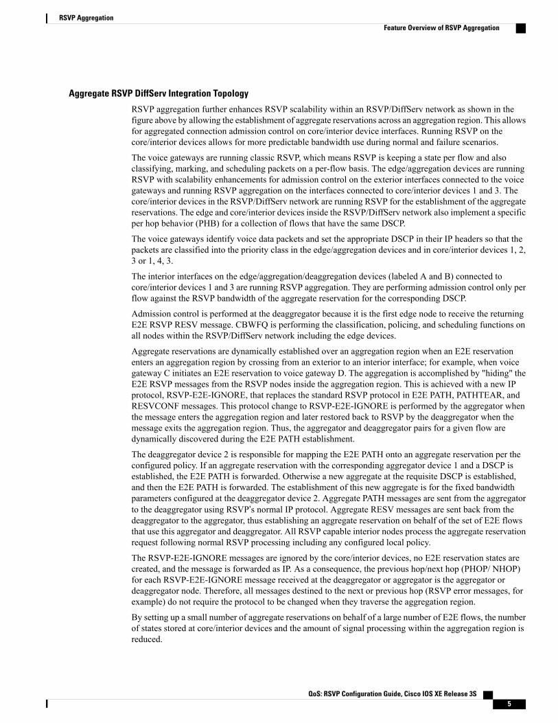
Aggregate RSVP DiffServ Integration Topology
RSVP aggregation further enhances RSVP scalability within an RSVP/DiffServ network as shown in thefigure above by allowing the establishment of aggregate reservations across an aggregation region. This allowsfor aggregated connection admission control on core/interior device interfaces. Running RSVP on thecore/interior devices allows for more predictable bandwidth use during normal and failure scenarios.
The voice gateways are running classic RSVP, which means RSVP is keeping a state per flow and alsoclassifying, marking, and scheduling packets on a per-flow basis. The edge/aggregation devices are runningRSVP with scalability enhancements for admission control on the exterior interfaces connected to the voicegateways and running RSVP aggregation on the interfaces connected to core/interior devices 1 and 3. Thecore/interior devices in the RSVP/DiffServ network are running RSVP for the establishment of the aggregatereservations. The edge and core/interior devices inside the RSVP/DiffServ network also implement a specificper hop behavior (PHB) for a collection of flows that have the same DSCP.
The voice gateways identify voice data packets and set the appropriate DSCP in their IP headers so that thepackets are classified into the priority class in the edge/aggregation devices and in core/interior devices 1, 2,3 or 1, 4, 3.
The interior interfaces on the edge/aggregation/deaggregation devices (labeled A and B) connected tocore/interior devices 1 and 3 are running RSVP aggregation. They are performing admission control only perflow against the RSVP bandwidth of the aggregate reservation for the corresponding DSCP.
Admission control is performed at the deaggregator because it is the first edge node to receive the returningE2E RSVP RESV message. CBWFQ is performing the classification, policing, and scheduling functions onall nodes within the RSVP/DiffServ network including the edge devices.
Aggregate reservations are dynamically established over an aggregation region when an E2E reservationenters an aggregation region by crossing from an exterior to an interior interface; for example, when voicegateway C initiates an E2E reservation to voice gateway D. The aggregation is accomplished by "hiding" theE2E RSVP messages from the RSVP nodes inside the aggregation region. This is achieved with a new IPprotocol, RSVP-E2E-IGNORE, that replaces the standard RSVP protocol in E2E PATH, PATHTEAR, andRESVCONF messages. This protocol change to RSVP-E2E-IGNORE is performed by the aggregator whenthe message enters the aggregation region and later restored back to RSVP by the deaggregator when themessage exits the aggregation region. Thus, the aggregator and deaggregator pairs for a given flow aredynamically discovered during the E2E PATH establishment.
The deaggregator device 2 is responsible for mapping the E2E PATH onto an aggregate reservation per theconfigured policy. If an aggregate reservation with the corresponding aggregator device 1 and a DSCP isestablished, the E2E PATH is forwarded. Otherwise a new aggregate at the requisite DSCP is established,and then the E2E PATH is forwarded. The establishment of this new aggregate is for the fixed bandwidthparameters configured at the deaggregator device 2. Aggregate PATH messages are sent from the aggregatorto the deaggregator using RSVP’s normal IP protocol. Aggregate RESV messages are sent back from thedeaggregator to the aggregator, thus establishing an aggregate reservation on behalf of the set of E2E flowsthat use this aggregator and deaggregator. All RSVP capable interior nodes process the aggregate reservationrequest following normal RSVP processing including any configured local policy.
The RSVP-E2E-IGNORE messages are ignored by the core/interior devices, no E2E reservation states arecreated, and the message is forwarded as IP. As a consequence, the previous hop/next hop (PHOP/ NHOP)for each RSVP-E2E-IGNORE message received at the deaggregator or aggregator is the aggregator ordeaggregator node. Therefore, all messages destined to the next or previous hop (RSVP error messages, forexample) do not require the protocol to be changed when they traverse the aggregation region.
By setting up a small number of aggregate reservations on behalf of a large number of E2E flows, the numberof states stored at core/interior devices and the amount of signal processing within the aggregation region isreduced.
QoS: RSVP Configuration Guide, Cisco IOS XE Release 3S 5
RSVP AggregationFeature Overview of RSVP Aggregation
In addition, by using differentiated services mechanisms for classification and scheduling of traffic supportedby aggregate reservations rather than performing per aggregate reservation classification and scheduling, theamount of classification and scheduling state in the aggregation region is further reduced. This reduction isindependent of the number of E2E reservations and the number of aggregate reservations in the aggregationregion. One or more RSVP/DiffServ DSCPs are used to identify the traffic covered by aggregate reservations,and one or more RSVP/DiffServ per hop behaviors (PHBs) are used to offer the required forwarding treatmentto this traffic. There may be more than one aggregate reservation between the same pair of devices, eachrepresenting different classes of traffic and each using a different DSCP and a different PHB.
Integration with RSVP FeaturesRSVP aggregation has been integrated with many RSVP features, including the following:
• RSVP Fast Local Repair
• RSVP Local Policy Support
• RSVP Refresh Reduction and Reliable Messaging
Benefits of RSVP Aggregation
Enhanced Scalability
Aggregating a large number of small reservations into one reservation requires fewer resources for signaling,setting, and maintaining the reservation thereby increasing scalability.
Enhanced Bandwidth Usage within RSVP/DiffServ Core Network
Aggregate reservations across an RSVP/DiffServ network allow for more predictable bandwidth use of corelinks across RSVP/DiffServ PHBs. Aggregate reservations can use RSVP fast local repair and local policypreemption features for determining bandwidth use during failure scenarios.
How to Configure RSVP Aggregation
Configuring RSVP Scalability EnhancementsPerform these tasks on all nodes within the aggregation region including aggregators, deaggregators, andinterior nodes.
Enabling RSVP on an InterfacePerform this task to enable RSVP on all the interfaces along the path from the sender to the receiver.
QoS: RSVP Configuration Guide, Cisco IOS XE Release 3S6
RSVP AggregationBenefits of RSVP Aggregation

SUMMARY STEPS
1. enable2. configure terminal3. ip routing4. ip vrf vrf-name5. exit6. interface type number7. ip vrf forwarding vrf-name8. ip rsvp bandwidth [interface-kbps] [single-flow-kbps]9. Repeat the previous step for each interface that you want to enable.10. end
DETAILED STEPS
PurposeCommand or Action
Enables privileged EXEC mode.enableStep 1
Example:
Device> enable
• Enter your password if prompted.
Enters global configuration mode.configure terminal
Example:
Device# configure terminal
Step 2
Enables IP routing.ip routing
Example:
Device(config)# ip routing
Step 3
Defines a VRF instance and enters VRF configurationmode.ip vrf vrf-name
Example:
Device(config)# ip vrf vrf1
Step 4
Exits VRF configuration mode and enters globalconfiguration mode.
exit
Example:
Device(config-vrf)# exit
Step 5
QoS: RSVP Configuration Guide, Cisco IOS XE Release 3S 7
RSVP AggregationConfiguring RSVP Scalability Enhancements
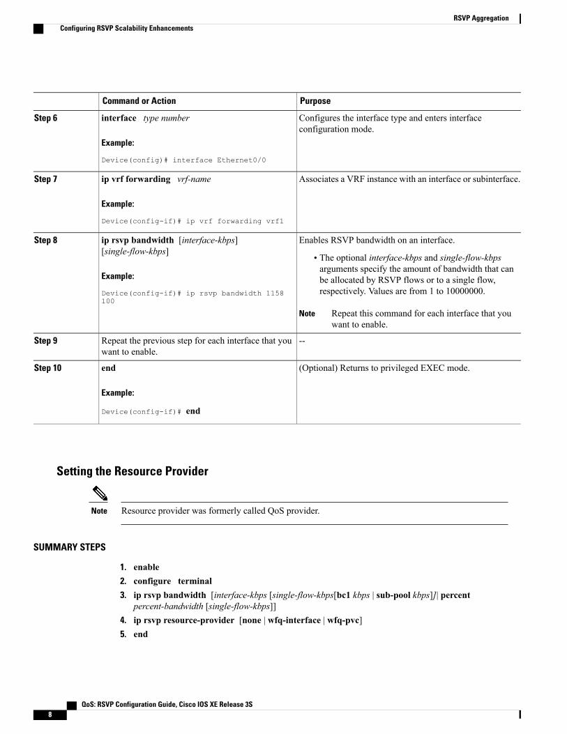
PurposeCommand or Action
Configures the interface type and enters interfaceconfiguration mode.
interface type number
Example:
Device(config)# interface Ethernet0/0
Step 6
Associates a VRF instance with an interface or subinterface.ip vrf forwarding vrf-name
Example:
Device(config-if)# ip vrf forwarding vrf1
Step 7
Enables RSVP bandwidth on an interface.ip rsvp bandwidth [interface-kbps][single-flow-kbps]
Step 8
• The optional interface-kbps and single-flow-kbpsarguments specify the amount of bandwidth that can
Example:
Device(config-if)# ip rsvp bandwidth 1158100
be allocated by RSVP flows or to a single flow,respectively. Values are from 1 to 10000000.
Repeat this command for each interface that youwant to enable.
Note
--Repeat the previous step for each interface that youwant to enable.
Step 9
(Optional) Returns to privileged EXEC mode.end
Example:
Device(config-if)# end
Step 10
Setting the Resource Provider
Resource provider was formerly called QoS provider.Note
SUMMARY STEPS
1. enable2. configure terminal3. ip rsvp bandwidth [interface-kbps [single-flow-kbps[bc1 kbps | sub-pool kbps]]| percent
percent-bandwidth [single-flow-kbps]]4. ip rsvp resource-provider [none | wfq-interface | wfq-pvc]5. end
QoS: RSVP Configuration Guide, Cisco IOS XE Release 3S8
RSVP AggregationConfiguring RSVP Scalability Enhancements

DETAILED STEPS
PurposeCommand or Action
Enables privileged EXEC mode.enableStep 1
Example:
Router> enable
• Enter your password if prompted.
Enters global configuration mode.configure terminal
Example:
Router# configure terminal
Step 2
Configures the interface type and enters interface configurationmode.
ip rsvp bandwidth [interface-kbps[single-flow-kbps[bc1 kbps | sub-pool kbps]]|percent percent-bandwidth [single-flow-kbps]]
Step 3
Example:
Router(config-if)# ip rsvp bandwidth 500500
Sets the resource provider.ip rsvp resource-provider [none |wfq-interface| wfq-pvc]
Step 4
• Enter the optional none keyword to set the resource providerto none regardless of whether one is configured on the interface.
Example:
Router(config-if)# ip rsvpresource-provider none
Setting the resource provider to none instructs RSVP to notassociate any resources, such as weighted fair queueing(WFQ) queues or bandwidth, with a reservation.
Note
• Enter the optional wfq-interface keyword to specify WFQ asthe resource provider on the interface.
• Enter the optional wfq-pvc keyword to specify WFQ as theresource provider on the permanent virtual circuit (PVC) orconnection.
(Optional) Returns to privileged EXEC mode.end
Example:
Router(config-if)# end
Step 5
QoS: RSVP Configuration Guide, Cisco IOS XE Release 3S 9
RSVP AggregationConfiguring RSVP Scalability Enhancements

Disabling Data Packet Classification
Disabling data packet classification instructs RSVP not to process every packet, but to perform admissioncontrol only.
Note
SUMMARY STEPS
1. enable2. configure terminal3. interface type slot / subslot / port4. ip rsvp data-packet classification none5. end
DETAILED STEPS
PurposeCommand or Action
Enables privileged EXEC mode.enableStep 1
Example:
Router> enable
• Enter your password if prompted.
Enters global configuration mode.configure terminal
Example:
Router# configure terminal
Step 2
Configures the interface type and enters interfaceconfiguration mode.
interface type slot / subslot / port
Example:
Router(config)# interface gigabitEthernet 0/0/0
Step 3
Disables data packet classification.ip rsvp data-packet classification none
Example:
Router(config-if)# ip rsvp data-packetclassification none
Step 4
(Optional) Returns to privileged EXEC mode.end
Example:
Router(config-if)# end
Step 5
QoS: RSVP Configuration Guide, Cisco IOS XE Release 3S10
RSVP AggregationConfiguring RSVP Scalability Enhancements

Configuring Class and Policy MapsTo configure class and policy maps, use the following commands, beginning in global configuration mode:
SUMMARY STEPS
1. Device(config)# class-map class-map-name2. Device(config)# policy-map policy-map-name
DETAILED STEPS
PurposeCommand or Action
Specifies the name of the class for which you want to create or modifyclass map match criteria.
Device(config)# class-map class-map-nameStep 1
Specifies the name of the policymap to be created, added to, or modifiedbefore you can configure policies for classes whose match criteria aredefined in a class map.
Device(config)# policy-mappolicy-map-name
Step 2
Attaching a Policy Map to an Interface
If at the time you configure the RSVP scalability enhancements, there are existing reservations that useclassic RSVP, no additional marking, classification, or scheduling is provided for these flows. You canalso delete these reservations after you configure the RSVP scalability enhancements.
Note
SUMMARY STEPS
1. enable2. configure terminal3. interface type slot / subslot / port4. service-policy [type access-control] {input | output} policy-map-name5. end
DETAILED STEPS
PurposeCommand or Action
Enables privileged EXEC mode.enableStep 1
QoS: RSVP Configuration Guide, Cisco IOS XE Release 3S 11
RSVP AggregationConfiguring RSVP Scalability Enhancements

PurposeCommand or Action
Example:
Router> enable
• Enter your password if prompted.
Enters global configuration mode.configure terminal
Example:
Router# configure terminal
Step 2
Configures the interface type and enters interface configuration mode.interface type slot / subslot / port
Example:
Router(config)# interfacegigabitEthernet 0/0/0
Step 3
Specifies the name of the policy map to be attached to the input or outputdirection of the interface.
service-policy [type access-control] {input| output} policy-map-name
Step 4
Example:
Router(config-if)# service-policyoutput POLICY-ATM
Policy maps can be attached in the input or output direction ofan interface. The direction and the router to which the policymap should be attached vary according to the networkconfiguration. When using the service-policy command toattach the policy map to an interface, be sure to choose therouter and the interface direction that are appropriate for thenetwork configuration.
Note
• The optional type access-control keywords determine the exactpattern to look for in the protocol stack of interest.
• Enter the policy-map name.
(Optional) Returns to privileged EXEC mode.end
Example:
Router(config-if)# end
Step 5
Configuring Interfaces with Aggregation RolePerform this task on aggregator and deaggregators to specify which interfaces are facing the aggregationregion.
QoS: RSVP Configuration Guide, Cisco IOS XE Release 3S12
RSVP AggregationConfiguring Interfaces with Aggregation Role

You do not need to perform this task on interior routers; that is, nodes having interior interfaces only.Note
SUMMARY STEPS
1. enable2. configure terminal3. interface type slot / subslot / port4. ip rsvp aggregation role interior5. Repeat Step 4 as needed to configure additional aggregator and deaggregator interfaces.6. end
DETAILED STEPS
PurposeCommand or Action
Enables privileged EXEC mode.enableStep 1
Example:
Router> enable
• Enter your password if prompted.
Enters global configuration mode.configure terminal
Example:
Router# configure terminal
Step 2
Configures the interface type and enters interfaceconfiguration mode.
interface type slot / subslot / port
Example:
Router(config)# interface gigabitEthernet 0/0/0
Step 3
Enables RSVP aggregation on an aggregator ordeaggregator’s interface.
ip rsvp aggregation role interior
Example:
Router(config-if)# ip rsvp aggregation roleinterior
Step 4
Configures additional aggregator and deaggregatorinterfaces.
Repeat Step 4 as needed to configure additional aggregatorand deaggregator interfaces.
Step 5
(Optional) Returns to privileged EXEC mode.end
Example:
Router(config-if)# end
Step 6
QoS: RSVP Configuration Guide, Cisco IOS XE Release 3S 13
RSVP AggregationConfiguring Interfaces with Aggregation Role
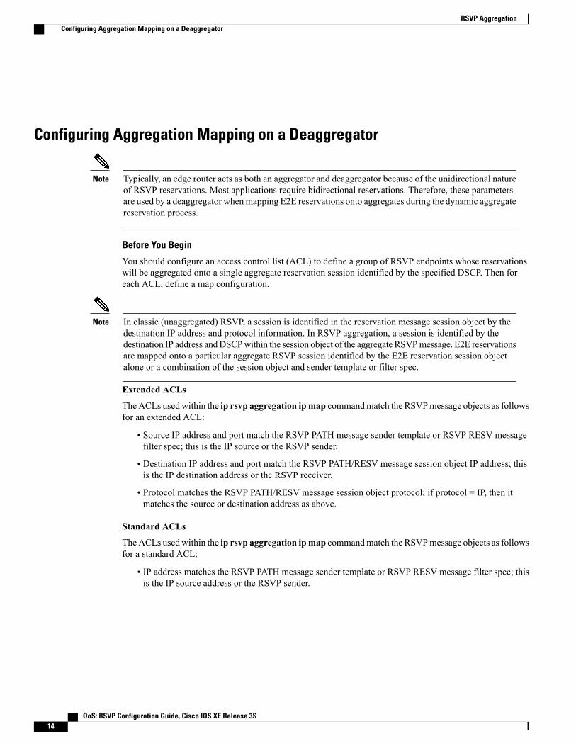
Configuring Aggregation Mapping on a Deaggregator
Typically, an edge router acts as both an aggregator and deaggregator because of the unidirectional natureof RSVP reservations. Most applications require bidirectional reservations. Therefore, these parametersare used by a deaggregator whenmapping E2E reservations onto aggregates during the dynamic aggregatereservation process.
Note
Before You Begin
You should configure an access control list (ACL) to define a group of RSVP endpoints whose reservationswill be aggregated onto a single aggregate reservation session identified by the specified DSCP. Then foreach ACL, define a map configuration.
In classic (unaggregated) RSVP, a session is identified in the reservation message session object by thedestination IP address and protocol information. In RSVP aggregation, a session is identified by thedestination IP address andDSCPwithin the session object of the aggregate RSVPmessage. E2E reservationsare mapped onto a particular aggregate RSVP session identified by the E2E reservation session objectalone or a combination of the session object and sender template or filter spec.
Note
Extended ACLs
TheACLs usedwithin the ip rsvp aggregation ipmap commandmatch the RSVPmessage objects as followsfor an extended ACL:
• Source IP address and port match the RSVP PATH message sender template or RSVP RESV messagefilter spec; this is the IP source or the RSVP sender.
• Destination IP address and port match the RSVP PATH/RESV message session object IP address; thisis the IP destination address or the RSVP receiver.
• Protocol matches the RSVP PATH/RESV message session object protocol; if protocol = IP, then itmatches the source or destination address as above.
Standard ACLs
TheACLs usedwithin the ip rsvp aggregation ipmap commandmatch the RSVPmessage objects as followsfor a standard ACL:
• IP address matches the RSVP PATH message sender template or RSVP RESV message filter spec; thisis the IP source address or the RSVP sender.
QoS: RSVP Configuration Guide, Cisco IOS XE Release 3S14
RSVP AggregationConfiguring Aggregation Mapping on a Deaggregator

SUMMARY STEPS
1. enable2. configure terminal3. ip rsvp aggregation ip map {access-list {acl-number} | any} dscp value4. end
DETAILED STEPS
PurposeCommand or Action
Enables privileged EXEC mode.enableStep 1
Example:
Router> enable
• Enter your password if prompted.
Enters global configuration mode.configure terminal
Example:
Router# configure terminal
Step 2
Configures RSVP aggregation rules that tell a router how tomap E2E reservations onto aggregate reservations.
ip rsvp aggregation ip map {access-list{acl-number} | any} dscp value
Step 3
Example:
Router(config)# ip rsvp aggregation ip mapany dscp af41
• The keywords and arguments specify additionalinformation such as DSCP values.
(Optional) Returns to privileged EXEC mode.end
Example:
Router(config)# end
Step 4
Configuring Aggregate Reservation Attributes on a DeaggregatorPerform this task on a deaggregator to configure the aggregate reservation attributes (also called token bucketparameters) on a per-DSCP basis.
QoS: RSVP Configuration Guide, Cisco IOS XE Release 3S 15
RSVP AggregationConfiguring Aggregate Reservation Attributes on a Deaggregator

Typically, an edge device acts as both an aggregator and deaggregator because of the unidirectional natureof RSVP reservations. Most applications require bidirectional reservations. Therefore, these parametersare used by a deaggregator whenmapping E2E reservations onto aggregates during the dynamic aggregatereservation process.
Note
SUMMARY STEPS
1. enable2. configure terminal3. ip rsvp aggregation ip reservation dscp value [aggregator agg-ip-address] traffic-params static
rate data-rate [burst burst-size] [peak peak-rate]4. end
DETAILED STEPS
PurposeCommand or Action
Enables privileged EXEC mode.enableStep 1
Example:
Device> enable
• Enter your password if prompted.
Enters global configuration mode.configure terminal
Example:
Device# configure terminal
Step 2
Configures RSVP aggregate reservation attributes (alsocalled token bucket parameters) on a per-DSCP basis.
ip rsvp aggregation ip reservation dscp value [aggregatoragg-ip-address] traffic-params static rate data-rate [burstburst-size] [peak peak-rate]
Step 3
• The keywords and arguments specify additionalinformation.
Example:
Device(config)# ip rsvp aggregation ip reservationdscp af11 aggregator 10.10.10.10 traffic-params staticrate 10 burst 8 peak 10
(Optional) Returns to privileged EXEC mode.end
Example:
Device(config)# end
Step 4
QoS: RSVP Configuration Guide, Cisco IOS XE Release 3S16
RSVP AggregationConfiguring Aggregate Reservation Attributes on a Deaggregator

Configuring an RSVP Aggregation Device IDPerform this task on aggregators and deaggregators to configure an RSVP aggregation device ID.
Both aggregators and deaggregators need to be identified with a stable and routable IP address. This isthe RFC 3175 device ID, which is also the IP address of the loopback interface with the lowest number.If there is no loopback interface configured or all those configured are down, then there will be no deviceID assigned for the aggregating/deaggregating function and aggregate reservations will not be established.
Note
The device ID may change if the associated loopback interface goes down or its IP address is removed.In this case, the E2E and aggregate sessions are torn down. If a new device ID is determined, new E2Eand aggregate sessions will use the new device ID.
Note
SUMMARY STEPS
1. enable2. configure terminal3. interface loopback number4. ip address ip-address subnet-mask/prefix5. end
DETAILED STEPS
PurposeCommand or Action
Enables privileged EXEC mode.enableStep 1
Example:
Device> enable
• Enter your password if prompted.
Enters global configuration mode.configure terminal
Example:
Device# configure terminal
Step 2
Creates a loopback interface and enters interfaceconfiguration mode.
interface loopback number
Example:
Device(config)# interface loopback 1
Step 3
• Enter a value for the number argument. The range is0 to 2147483647.
QoS: RSVP Configuration Guide, Cisco IOS XE Release 3S 17
RSVP AggregationConfiguring an RSVP Aggregation Device ID
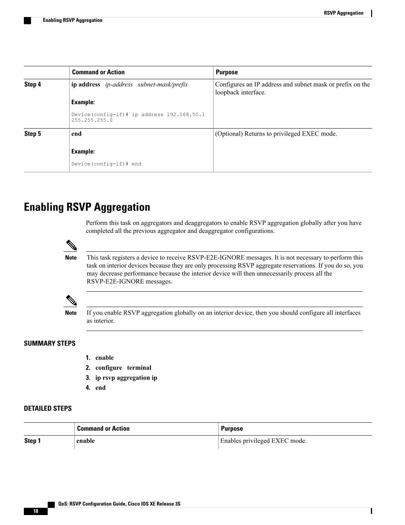
PurposeCommand or Action
Configures an IP address and subnet mask or prefix on theloopback interface.
ip address ip-address subnet-mask/prefix
Example:
Device(config-if)# ip address 192.168.50.1255.255.255.0
Step 4
(Optional) Returns to privileged EXEC mode.end
Example:
Device(config-if)# end
Step 5
Enabling RSVP AggregationPerform this task on aggregators and deaggregators to enable RSVP aggregation globally after you havecompleted all the previous aggregator and deaggregator configurations.
This task registers a device to receive RSVP-E2E-IGNORE messages. It is not necessary to perform thistask on interior devices because they are only processing RSVP aggregate reservations. If you do so, youmay decrease performance because the interior device will then unnecessarily process all theRSVP-E2E-IGNORE messages.
Note
If you enable RSVP aggregation globally on an interior device, then you should configure all interfacesas interior.
Note
SUMMARY STEPS
1. enable2. configure terminal3. ip rsvp aggregation ip4. end
DETAILED STEPS
PurposeCommand or Action
Enables privileged EXEC mode.enableStep 1
QoS: RSVP Configuration Guide, Cisco IOS XE Release 3S18
RSVP AggregationEnabling RSVP Aggregation

PurposeCommand or Action
Example:
Device> enable
• Enter your password if prompted.
Enters global configuration mode.configure terminal
Example:
Device# configure terminal
Step 2
Enables RSVP aggregation globally on an aggregator ordeaggregator.
ip rsvp aggregation ip
Example:
Device(config)# ip rsvp aggregation ip
Step 3
(Optional) Returns to privileged EXEC mode.end
Example:
Device(config)# end
Step 4
Configuring RSVP Local PolicyPerform this task to apply a local policy to an RSVP aggregate reservation.
In classic (unaggregated) RSVP, a session is identified in the reservation message session object by thedestination IP address and protocol information. In RSVP aggregation, a session is identified by thedestination IP address and DSCP within the session object of the aggregate RSVP message. The dscp-ipkeyword matches the DSCP within the session object.
Note
SUMMARY STEPS
1. enable2. configure terminal3. ip rsvp policy local {acl acl1[acl2...acl8] | dscp-ip value1 [value2 ... value8] | default | identity alias1
[alias2...alias4] | origin-as as1[as2...as8]}4. {accept | forward [all | path| path-error | resv| resv-error] | default | exit | fast-reroute | local-override
|maximum {bandwidth [group x] [single y] | senders n}| preempt-priority [traffic-eng x] setup-priority[hold-priority]}
5. end
QoS: RSVP Configuration Guide, Cisco IOS XE Release 3S 19
RSVP AggregationConfiguring RSVP Local Policy

DETAILED STEPS
PurposeCommand or Action
Enables privileged EXEC mode.enableStep 1
Example:
Router> enable
• Enter your password if prompted.
Enters global configuration mode.configure terminal
Example:
Router# configure terminal
Step 2
Creates a local policy to determine how RSVP resources are used ina network and enters local policy configuration mode.
ip rsvp policy local {acl acl1[acl2...acl8] | dscp-ipvalue1 [value2 ... value8] | default | identity alias1[alias2...alias4] | origin-as as1[as2...as8]}
Step 3
• Enter the dscp-ip valuekeyword and argument combination tospecify a DSCP for matching the session object DCSP withinthe aggregate reservations. Values can be the following:Example:
Router(config)# ip rsvp policy local dscp-ip46
• 0 to 63--Numerical. The default value is 0.
• af11 to af43--Assured forwarding (AF).
• cs1 to cs7--Type of service (ToS) precedence.
• default--Default DSCP.
• ef--Expedited Forwarding (EF).
You must associate at least one DSCP with a DSCP-basedpolicy. However, you can associate as many as eight.
Note
(Optional) Defines the properties of the dscp-ip local policy that youare creating. (These are the submode commands.)
{accept | forward [all | path| path-error | resv|resv-error] | default | exit | fast-reroute |
Step 4
local-override |maximum {bandwidth [group This is an optional step. An empty policy rejects everything,which may be desired in some cases.
Note
See the ip rsvp policy local command for more detailed informationon submode commands.
x] [single y] | senders n}| preempt-priority[traffic-eng x] setup-priority [hold-priority]}
Example:
Router(config-rsvp-policy-local)# forwardall
(Optional) Exits local policy configuration mode and returns toprivileged EXEC mode.
end
Example:
Router(config-rsvp-policy-local)# end
Step 5
QoS: RSVP Configuration Guide, Cisco IOS XE Release 3S20
RSVP AggregationConfiguring RSVP Local Policy

Verifying the RSVP Aggregation Configuration
You can use the following show commands in user EXEC or privileged EXEC mode.Note
SUMMARY STEPS
1. enable2. show ip rsvp aggregation ip [endpoints | interface [if-name] |map [dscp value]| reservation [dscp
value[aggregator ip-address]]3. show ip rsvp aggregation ip endpoints [role{aggregator| deaggregator}] [ip-address] [dscp value]
[detail]4. show ip rsvp [atm-peak-rate-limit| counters| host| installed| interface| listeners| neighbor| policy|
precedence| request| reservation| sbm| sender| signalling| tos]5. show ip rsvp reservation [detail] [filter[destination ip-address | hostname] [dst-port port-number]
[source ip-address | hostname][src-port port-number]]6. show ip rsvp sender [detail] [filter[destination ip-address | hostname] [dst-port port-number] [source
ip-address | hostname][src-port port-number]]7. show ip rsvp installed [interface-type interface-number] [detail]8. show ip rsvp interface [detail] [interface-type interface-number]9. end
DETAILED STEPS
PurposeCommand or Action
(Optional) Enables privileged EXEC mode.enableStep 1
Example:
Device> enable
• Enter your password if prompted.
Skip this step if you are using the show commands inuser EXEC mode.
Note
(Optional) Displays RSVP summary aggregation information.show ip rsvp aggregation ip [endpoints | interface[if-name] |map [dscp value]| reservation [dscpvalue[aggregator ip-address]]
Step 2
• The optional keywords and arguments display additionalinformation.
Example:
Device# show ip rsvp aggregation ip
(Optional) Displays RSVP information about aggregator anddeaggregator devices for currently established aggregatereservations.
show ip rsvp aggregation ip endpoints[role{aggregator| deaggregator}] [ip-address] [dscpvalue] [detail]
Step 3
QoS: RSVP Configuration Guide, Cisco IOS XE Release 3S 21
RSVP AggregationVerifying the RSVP Aggregation Configuration

PurposeCommand or Action
Example:
Device# show ip rsvp aggregation ip endpooints
• The optional keywords and arguments display additionalinformation.
(Optional) Displays specific information for RSVP categories.show ip rsvp [atm-peak-rate-limit| counters| host|installed| interface| listeners| neighbor| policy|
Step 4
• The optional keywords display additional information.precedence| request| reservation| sbm| sender|signalling| tos]
Example:
Device# show ip rsvp
(Optional) Displays RSVP-related receiver information currentlyin the database.
show ip rsvp reservation [detail] [filter[destinationip-address | hostname] [dst-port port-number] [sourceip-address | hostname][src-port port-number]]
Step 5
• The optional keywords and arguments display additionalinformation.
Example:
Device# show ip rsvp reservation detail The optional filter keyword is supported in Cisco IOSReleases 12.0S and 12.2S only.
Note
(Optional) Displays RSVP PATH-related sender informationcurrently in the database.
show ip rsvp sender [detail] [filter[destinationip-address | hostname] [dst-port port-number] [sourceip-address | hostname][src-port port-number]]
Step 6
• The optional keywords and arguments display additionalinformation.
Example:
Device# show ip rsvp sender detail The optional filter keyword is supported in Cisco IOSReleases 12.0S and 12.2S only.
Note
(Optional) Displays RSVP-related installed filters andcorresponding bandwidth information.
show ip rsvp installed [interface-type interface-number][detail]
Step 7
Example:
Device# show ip rsvp installed detail
• The optional keywords and arguments display additionalinformation.
(Optional) Displays RSVP-related interface information.show ip rsvp interface [detail] [interface-typeinterface-number]
Step 8
• The optional keywords and arguments display additionalinformation.
Example:
Device# show ip rsvp interface detail
(Optional) Exits privileged EXEC mode and returns to userEXEC mode.
end
Example:
Device# end
Step 9
QoS: RSVP Configuration Guide, Cisco IOS XE Release 3S22
RSVP AggregationVerifying the RSVP Aggregation Configuration
Configuration Examples for RSVP Aggregation
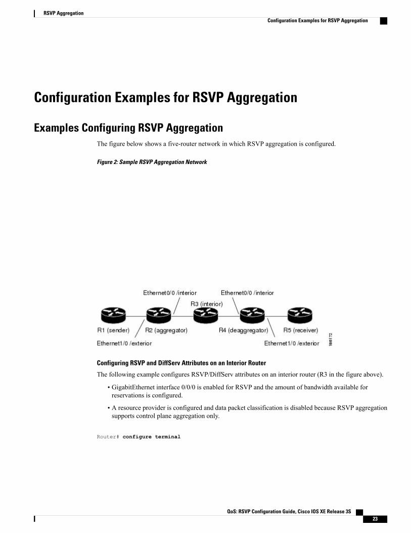
Examples Configuring RSVP AggregationThe figure below shows a five-router network in which RSVP aggregation is configured.
Figure 2: Sample RSVP Aggregation Network
Configuring RSVP and DiffServ Attributes on an Interior Router
The following example configures RSVP/DiffServ attributes on an interior router (R3 in the figure above).
• GigabitEthernet interface 0/0/0 is enabled for RSVP and the amount of bandwidth available forreservations is configured.
• A resource provider is configured and data packet classification is disabled because RSVP aggregationsupports control plane aggregation only.
Router# configure terminal
QoS: RSVP Configuration Guide, Cisco IOS XE Release 3S 23
RSVP AggregationConfiguration Examples for RSVP Aggregation
Enter configuration commands, one per line. End with CNTL/Z.Router(config)# interface GigabitEthernet 0/0/0
Router(config-if)# ip rsvp bandwidth 400
Router(config-if)# ip rsvp resource-provider none
Router(config-if)# ip rsvp data-packet classification none
Router(config-if)# end
Configuring RSVP Aggregation on an Aggregator or Deaggregator
The following example configures RSVP aggregation attributes on an aggregator or deaggregator (R2 andR4 in the figure above):
• Loopback 1 is configured to establish an RSVP aggregation router ID.
• Ethernet interface 0/0 is enabled for RSVP and the amount of bandwidth available for reservations isconfigured.
• Ethernet interface 0/0 on an aggregator or deaggregator is configured to face an aggregation region.
• A resource provider is configured and data packet classification is disabled because RSVP aggregationsupports control plane aggregation only.
Router# configure terminal
Enter configuration commands, one per line. End with CNTL/Z.Router(config)# interface Loopback 1Router(config)# ip address 192.168.50.1 255.255.255.0Router(config)# interface GigabitEthernet 0/0/0Router(config-if)# ip rsvp bandwidth 400Router(config-if)# ip rsvp aggregation role interiorRouter(config-if)# ip rsvp resource-provider noneRouter(config-if)# ip rsvp data-packet classification noneRouter(config-if)# end
Configuring RSVP Aggregation Attributes and Parameters
The following example configures additional RSVP aggregation attributes, including a global rule for mappingall E2E reservations onto a single aggregate with DSCP AF41 and the token bucket parameters for aggregatereservations, because dynamic resizing is not supported. This configuration is only required on nodes performingthe deaggregation function (R4 in the figure above).
Router# configure terminal
Enter configuration commands, one per line. End with CNTL/Z.
Router(config)# ip rsvp aggregation ip map any dscp af41
Router(config)# ip rsvp aggregation ip reservation dscp af41 aggregator 10.10.10.10 traffic-paramsstatic rate 10 burst 8 peak 10
Router(config)# end
QoS: RSVP Configuration Guide, Cisco IOS XE Release 3S24
RSVP AggregationExamples Configuring RSVP Aggregation

Configuring an Access List for a Deaggregator
In the following example, access list 1 is defined for all RSVP messages whose RSVP PATH message sendertemplate source address is in the 10.1.0.0 subnet so that the deaggregator (R4 in the figure above) maps thosereservations onto an aggregate reservation for the DSCP associated with the AF41 PHB:
Router# configure terminal
Enter configuration commands, one per line. End with CNTL/Z.
Router(config)# access-list 1 permit 10.1.0.0 0.0.255.255
Router(config)# ip rsvp aggregation ip map access-list 1 dscp af41
Router(config)# end
Configuring RSVP Aggregation
After you configure your RSVP aggregation attributes, you are ready to enable aggregation globally.
When you enable aggregation on a router, the router can act as an aggregator or a deaggregator. To performaggregator and deaggregator functions, the RSVP process must see messages with the RSVP-E2E-IGNOREprotocol type (134) on a router; otherwise, the messages are forwarded as data by the router's data plane. Theip rsvp aggregation ip command enables RSVP to identify messages with the RSVP-E2E-IGNORE protocol.
This registers a router to receive RSVP-E2E-IGNORE messages. It is not necessary to configure thiscommand on interior nodes that are only processing RSVP aggregate reservations and forwardingRSVP-E2E-IGNORE messages as IP datagrams). Since the router is loaded with an image that supportsaggregation, the router will process aggregate (RFC 3175 formatted) messages correctly. Enablingaggregation on an interior modemay decrease performance because the interior node will then unnecessarilyprocess all RSVP-E2E-IGNORE messages.
Note
If you enable aggregation on an interior node, you must configure all its interfaces as interior. Otherwise,all the interfaces have the exterior role, and any E2E PATH (E2E-IGNORE) messages arriving at therouter are discarded.
Note
In summary, there are two options for an interior router (R3 in the figure above):
• No RSVP aggregation configuration commands are entered.
• RSVP aggregation is enabled and all interfaces are configured as interior.
Configuring RSVP Local Policy
You can configure a local policy optionally on any RSVP capable node. In this example, a local policy isconfigured on a deaggregator to set the preemption priority values within the RSVPRESV aggregate messagesbased uponmatching the DSCPwithin the aggregate RSVPmessages session object. This allows the bandwidthavailable for RSVP reservations to be used first by reservations of DSCP EF over DSCP AF41 on interior oraggregation nodes. Any aggregate reservation for another DSCP will have a preemption priority of 0, thedefault.
QoS: RSVP Configuration Guide, Cisco IOS XE Release 3S 25
RSVP AggregationExamples Configuring RSVP Aggregation

Within the RSVP RESV aggregate message at the deaggregator, this local policy sets an RFC 3181"Signaled Preemption Priority Policy Element" that can be used by interior nodes or the aggregator thathas ip rsvp preemption enabled.
Note
The following example sets the preemption priority locally for RSVP aggregate reservations duringestablishment on an interior router (R3 in the figure above):
Router# configure terminal
Enter configuration commands, one per line. End with CNTL/Z.
Router(config)# ip rsvp policy local dscp-ip ef
Router(config-rsvp-local-policy)# 5 5
Router(config-rsvp-local-policy)# exit
Router(config)# ip rsvp policy local dscp-ip af41
Router(config-rsvp-local-policy)# 2 2
Router(config-rsvp-local-policy)# end
Example Verifying the RSVP Aggregation Configuration
Verifying RSVP Aggregation and Configured Reservations
The following example verifies that RSVP aggregation is enabled and displays information about thereservations currently established and configured map and reservation policies:
Router# show ip rsvp aggregation ipRFC 3175 Aggregation: EnabledLevel: 1Default QoS service: Controlled-LoadNumber of signaled aggregate reservations: 2Number of signaled E2E reservations: 8Number of configured map commands: 4Number of configured reservation commands: 1
Verifying Configured Interfaces and Their Roles
The following example displays the configured interfaces and whether they are interior or exterior in regardto the aggregation region:
Router# show ip rsvp aggregation ip interfaceInterface Name Role-------------------- --------Ethernet0/0 interiorSerial2/0 exteriorSerial3/0 exterior
QoS: RSVP Configuration Guide, Cisco IOS XE Release 3S26
RSVP AggregationExample Verifying the RSVP Aggregation Configuration

Verifying Aggregator and Deaggregator Reservations
The following example displays information about the aggregators and deaggregators when establishedreservations are present:
Router# show ip rsvp aggregation ip endpoints detailRole DSCP Aggregator Deaggregator State Rate Used QBM PoolID----- ---- --------------- --------------- ------ ------- ------- ----------Agg 46 10.3.3.3 10.4.4.4 ESTABL 100K 100K 0x00000003
Aggregate Reservation for the following E2E Flows (PSBs):To From Pro DPort Sport Prev Hop I/F BPS10.4.4.4 10.1.1.1 UDP 1 1 10.23.20.3 Et1/0 100K
Aggregate Reservation for the following E2E Flows (RSBs):To From Pro DPort Sport Next Hop I/F Fi Serv BPS10.4.4.4 10.1.1.1 UDP 1 1 10.4.4.4 Se2/0 FF RATE 100K
Aggregate Reservation for the following E2E Flows (Reqs):To From Pro DPort Sport Next Hop I/F Fi Serv BPS10.4.4.4 10.1.1.1 UDP 1 1 10.23.20.3 Et1/0 FF RATE 100K
Additional ReferencesThe following sections provide references related to the RSVP Application ID Support feature.
Related Documents
Document TitleRelated Topic
Cisco IOS Quality of Service Solutions CommandReference
QoS commands: complete command syntax,command modes, command history, defaults, usageguidelines, and examples
"Configuring RSVP" moduleQoS configuration tasks related to RSVP
"Overview of Cisco Unified CommunicationsManager and Cisco IOS Interoperability" module
Cisco United Communications Manager(CallManager) and related features
"Using the Cisco IOS Command-Line Interface"module
Regular expressions
Cisco IOS Master Commands List, All ReleasesCisco IOS commands
Standards
TitleStandard
--No new or modified standards are supported by thisfeature, and support for existing standards has notbeen modified by this feature.
QoS: RSVP Configuration Guide, Cisco IOS XE Release 3S 27
RSVP AggregationAdditional References
MIBs
MIBs LinkMIB
To locate and downloadMIBs for selected platforms,Cisco IOS releases, and feature sets, use Cisco MIBLocator found at the following URL:
http://www.cisco.com/go/mibs
No new or modified MIBs are supported by thisfeature, and support for existing MIBs has not beenmodified by this feature.
RFCs
TitleRFC
Resource ReSerVation Protocol (RSVP)RFC 2205
Application and Sub Application Identity PolicyElement for Use with RSVP
RFC 2872
Signaled Preemption Priority Policy ElementRFC 3181
Identity Representation for RSVPRFC 3182
Technical Assistance
LinkDescription
http://www.cisco.com/cisco/web/support/index.htmlThe Cisco Support and Documentation websiteprovides online resources to download documentation,software, and tools. Use these resources to install andconfigure the software and to troubleshoot and resolvetechnical issues with Cisco products and technologies.Access to most tools on the Cisco Support andDocumentation website requires a Cisco.com user IDand password.
Feature Information for RSVP AggregationThe following table provides release information about the feature or features described in this module. Thistable lists only the software release that introduced support for a given feature in a given software releasetrain. Unless noted otherwise, subsequent releases of that software release train also support that feature.
Use Cisco Feature Navigator to find information about platform support and Cisco software image support.To access Cisco Feature Navigator, go to www.cisco.com/go/cfn. An account on Cisco.com is not required.
QoS: RSVP Configuration Guide, Cisco IOS XE Release 3S28
RSVP AggregationFeature Information for RSVP Aggregation

Table 1: Feature Information for RSVP Aggregation
Feature InformationReleasesFeature Name
The RSVP Aggregation featureallows the Resource ReservationProtocol (RSVP) state to bereduced within an RSVP/DiffServnetwork by aggregating manysmaller reservations into a single,larger reservation at the edge.
The following commands wereintroduced or modified: debug iprsvp aggregation, debug qbm, iprsvp aggregation ip, ip rsvpaggregation ip map, ip rsvpaggregation, ip reservation dscptraffic-params static rate, ip rsvpaggregation ip role interior, iprsvp policy local, show ip rsvp,show ip rsvp aggregation ip,show ip rsvp aggregation ipendpoints, show ip rsvp installed,show ip rsvp interface, show iprsvp policy local, show ip rsvprequest, show ip rsvpreservation, show ip rsvp sender,show qbm client, show qbmpool.
In Cisco IOS XE Release 3.8S,support was added for the CiscoASR 903 Router.
Cico IOS XE Release 2.6
Cisco IOS XE Release 3.8S
RSVP Aggregation
Glossaryadmission control --The process by which an RSVP reservation is accepted or rejected on the basis ofend-to-end available network resources.
aggregate --AnRSVP flow that represents multiple end-to-end (E2E) flows; for example, a MultiprotocolLabel Switching Traffic Engineering (MPLS-TE) tunnel may be an aggregate for many E2E flows.
aggregation region --An area where E2E flows are represented by aggregate flows, with aggregators anddeaggregators at the edge; for example, an MPLS-TE core, where TE tunnels are aggregates for E2E flows.An aggregation region contains a connected set of nodes that are capable of performing RSVP aggregation.
aggregator --The device that processes the E2E PATH message as it enters the aggregation region. Thisdevice is also called the TE tunnel head-end device; it forwards the message from an exterior interface to aninterior interface.
bandwidth --The difference between the highest and lowest frequencies available for network signals. Theterm is also used to describe the rated throughput capacity of a given network medium or protocol.
QoS: RSVP Configuration Guide, Cisco IOS XE Release 3S 29
RSVP AggregationGlossary
deaggregator --The device that processes the E2E PATH message as it leaves the aggregation region. Thisdevice is also called the TE tunnel tail-end device; it forwards the message from an interior interface to anexterior interface.
E2E --end-to-end. An RSVP flow that crosses an aggregation region, and whose state is represented inaggregate within this region, such as a classic RSVP unicast flow crossing an MPLS-TE core.
LSP --label-switched path. A configured connection between two devices, in which label switching is usedto carry the packets. The purpose of an LSP is to carry data packets.
QoS --quality of service. A measure of performance for a transmission system that reflects its transmissionquality and service availability.
RSVP --Resource Reservation Protocol. A protocol that supports the reservation of resources across an IPnetwork. Applications running on IP end systems can use RSVP to indicate to other nodes the nature (bandwidth,jitter, maximum burst, and so on) of the packet streams that they want to receive.
state --Information that a device must maintain about each LSP. The information is used for rerouting tunnels.
TE --traffic engineering. The techniques and processes used to cause routed traffic to travel through thenetwork on a path other than the one that would have been chosen if standard routing methods had been used.
tunnel --Secure communications path between two peers, such as two devices.
QoS: RSVP Configuration Guide, Cisco IOS XE Release 3S30
RSVP AggregationGlossary
C H A P T E R 2RSVP Application ID Support
The RSVP Application ID Support feature introduces application-specific reservations, which enhance thegranularity for local policy match criteria so that you can manage quality of service (QoS) on the basis ofapplication type.
• Finding Feature Information, page 31
• Prerequisites for RSVP Application ID Support, page 31
• Restrictions for RSVP Application ID Support, page 32
• Information About RSVP Application ID Support, page 32
• How to Configure RSVP Application ID Support, page 35
• Configuration Examples for RSVP Application ID Support, page 44
• Additional References, page 48
• Feature Information for RSVP Application ID Support, page 50
• Glossary, page 50
Finding Feature InformationYour software release may not support all the features documented in this module. For the latest caveats andfeature information, see Bug Search Tool and the release notes for your platform and software release. Tofind information about the features documented in this module, and to see a list of the releases in which eachfeature is supported, see the feature information table at the end of this module.
Use Cisco Feature Navigator to find information about platform support and Cisco software image support.To access Cisco Feature Navigator, go to www.cisco.com/go/cfn. An account on Cisco.com is not required.
Prerequisites for RSVP Application ID SupportYou must configure Resource Reservation Protocol (RSVP) on one or more interfaces on at least twoneighboring routers that share a link within the network.
QoS: RSVP Configuration Guide, Cisco IOS XE Release 3S 31
Restrictions for RSVP Application ID Support• RSVP policies apply only to PATH, RESV, PATHERROR, and RESVERROR messages.
• Merging of global and interface-based local policies is not supported; therefore, you cannot match onmultiple policies.
Information About RSVP Application ID Support
Feature Overview of RSVP Application ID Support
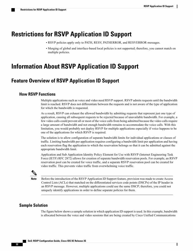
How RSVP FunctionsMultiple applications such as voice and video need RSVP support. RSVP admits requests until the bandwidthlimit is reached. RSVP does not differentiate between the requests and is not aware of the type of applicationfor which the bandwidth is requested.
As a result, RSVP can exhaust the allowed bandwidth by admitting requests that represent just one type ofapplication, causing all subsequent requests to be rejected because of unavailable bandwidth. For example, afew video calls could prevent all or most of the voice calls from being admitted because the video calls requirea large amount of bandwidth and not enough bandwidth remains to accommodate the voice calls. With thislimitation, you would probably not deploy RSVP for multiple applications especially if voice happens to beone of the applications for which RSVP is required.
The solution is to allow configuration of separate bandwidth limits for individual applications or classes oftraffic. Limiting bandwidth per application requires configuring a bandwidth limit per application and havingeach reservation flag the application to which the reservation belongs so that it can be admitted against theappropriate bandwidth limit.
Application and Sub Application Identity Policy Element for Use with RSVP (Internet Engineering TaskForce (IETF) RFC 2872) allows for creation of separate bandwidth reservation pools. For example, an RSVPreservation pool can be created for voice traffic, and a separate RSVP reservation pool can be created forvideo traffic. This prevents video traffic from overwhelming voice traffic.
Before the introduction of the RSVPApplication ID Support feature, provision was made to create AccessControl Lists (ACLs) that matched on the differentiated services code points (DSCPs) of the IP header inan RSVP message. However, multiple applications could use the same DSCP; therefore, you could notuniquely identify applications in order to define separate policies for them.
Note
Sample SolutionThe figure below shows a sample solution in which application ID support is used. In this example, bandwidthis allocated between the voice and video sessions that are being created by Cisco Unified Communications
QoS: RSVP Configuration Guide, Cisco IOS XE Release 3S32
RSVP Application ID SupportRestrictions for RSVP Application ID Support

Manager (CUCM). Video requires muchmore bandwidth than voice, and if you do not separate the reservations,the video traffic could overwhelm the voice traffic.
CUCM uses the RSVP Application ID Support feature. In this example, when CUCM makes the RSVPreservation, CUCM can specify whether the reservation should be made against a video RSVP bandwidthpool or a voice RSVP bandwidth pool. If not enough bandwidth remains in the requested pool, even thoughthere is enough bandwidth in the total RSVP allocation, RSVP signals CUCM that there is a problem withthe reservation. The figure below shows some of the signaling and data traffic that is sent during the sessionsetup.
IMAGE MISSING; embedded not referenced
In this scenario, the IP phones and IP video devices do not directly support RSVP. In order to allow RSVPto reserve the bandwidth for these devices, the RSVP agent component in the Cisco IOS router creates thereservation. While setting up the voice or video session, CUCM communicates with the RSVP agent andsends the parameters to reserve the necessary bandwidth.
When you want to make a voice or video call, the device signals CUCM. CUCM signals the RSVP agent,specifying the RSVP application ID that corresponds to the type of call, which is voice or video in this example.The RSVP agents establish the RSVP reservation across the network and communicate to CUCM that thereservation has been made. CUCM then completes the session establishment, and the Real-Time TransportProtocol (RTP) traffic streams flow between the phones (or video devices). If the RSVP agents are unable tocreate the bandwidth reservations for the requested application ID, they communicate that information backto CUCM, which signals this information back to you.
Global and per-Interface RSVP PoliciesYou can configure RSVP policies globally and on a per-interface basis. You can also configure multiple globalpolicies and multiple policies per interface.
Global RSVP policies restrict howmuch RSVP bandwidth a router uses regardless of the number of interfaces.You should configure a global policy if your router has CPU restrictions, one interface, or multiple interfacesthat do not require different bandwidth limits.
Per-interface RSVP policies allow you to configure separate bandwidth pools with varying limits so that noone application, such as video, can consume all the RSVP bandwidth on a specified interface at the expenseof other applications, such as voice, which would be dropped. You should configure a per-interface policywhen you need greater control of the available bandwidth.
How RSVP Policies Are AppliedRSVP searches for policies whenever an RSVPmessage is processed. The policy informs RSVP if any specialhandling is required for that message.
If your network configuration has global and per-interface RSVP policies, the per-interface policies are appliedfirst; that is, the RSVP looks for policy-match criteria in the order in which the policies were configured.RSVP searches for policy-match criteria in the following order:
• Nondefault interface policies
• Default interface policy
• Nondefault global policies
• Global default policy
QoS: RSVP Configuration Guide, Cisco IOS XE Release 3S 33
RSVP Application ID SupportFeature Overview of RSVP Application ID Support
If RSVP finds no policy-match criteria, it accepts all incoming messages. To change this decision from acceptto reject, use the ip rsvp policy default-reject command.
PreemptionPreemption happens when one reservation receives priority over another because there is insufficient bandwidthin an RSVP pool. There are two types of RSVP bandwidth pools: local policy pools and interface pools. Localpolicies can be global or interface-specific. RSVP performs admission control against these pools when aRESV message arrives.
If an incoming reservation request matches an RSVP local policy that has an RSVP bandwidth limit (asconfigured with themaximumbandwidth group submode command) and that limit has been reached, RSVPtries to preempt other lower-priority reservations admitted by that policy. When there are too few of theselower-priority reservations, RSVP rejects the incoming reservation request. Then RSVP looks at the interfacebandwidth pool that you configured by using the ip rsvp bandwidth command. If that bandwidth limit hasbeen reached, RSVP tries to preempt other lower-priority reservations on that interface to accommodate thenew reservation request. At this point, RSVP does not consider which local policies admitted the reservations.When not enough bandwidth on that interface pool can be preempted, RSVP rejects the new reservation eventhough the new reservation was able to obtain bandwidth from the local policy pool.
Preemption can also happen when you manually reconfigure an RSVP bandwidth pool of any type to a lowervalue such that the existing reservations using that pool no longer fit in the pool.
How Preemption Priorities Are Assigned and Signaled
If a received RSVP PATH or RESV message contains preemption priorities (signaled with an IETF RFC3181 preemption priority policy element inside an IETF RFC 2750 POLICY_DATA object) and the prioritiesare higher than those contained in the matching local policy (if any), the offending message is rejected and aPATHERROR or RESVERRORmessage is sent in response. If the priorities are approved by the local policy,they are stored with the RSVP state in the device and forwarded to its neighbors.
If a received RSVP PATH or RESV message does not contain preemption priorities (as previously described)and you issued a global ip rsvp policy preempt command, and the message matches a local policy thatcontains a preempt-priority command, a POLICY_DATA object with a preemption priority element thatcontains the local policy’s priorities is added to the message as part of the policy decision. These prioritiesare then stored with the RSVP state in the device and forwarded to neighbors.
Controlling Preemption
The ip rsvp policy preempt command controls whether a router preempts any reservations when required.When you issue this command, a RESV message that subsequently arrives on an interface can preempt thebandwidth of one or more reservations on that interface if the assigned setup priority of the new reservationis higher than the assigned hold priorities of the installed reservations.
Benefits of RSVP Application ID SupportThe RSVP Application ID Support feature provides the following benefits:
• Allows RSVP to identify applications uniquely and to separate bandwidth pools to be created for differentapplications so that one application cannot consume all the available bandwidth, thereby forcing othersto be dropped.
QoS: RSVP Configuration Guide, Cisco IOS XE Release 3S34
RSVP Application ID SupportBenefits of RSVP Application ID Support

• Integrates with the RSVP agent and CUCM to provide a solution for call admission control (CAC) andQoS for VoIP and video conferencing applications in networks with multitiered, meshed topologiesusing signaling protocols such as Signaling Connection Control Part (SCCP) to ensure that a singleapplication does not overwhelm the available reserved bandwidth.
• Functions with any endpoint that complies with RFC 2872 or RFC 2205.
How to Configure RSVP Application ID SupportYou can configure application IDs and local policies to use with RSVP-aware software programs such asCUCM or to use with non-RSVP-aware applications such as static PATH and RESV messages.
Configuring RSVP Application ID for RSVP-Aware Software Programs
Configuring an RSVP Application ID
SUMMARY STEPS
1. enable2. configure terminal3. ip rsvp policy identity alias policy-locator locator4. Repeat Step 3 as needed to configure additional application IDs.5. end
DETAILED STEPS
PurposeCommand or Action
Enables privileged EXEC mode.enableStep 1
Example:
Router> enable
• Enter your password if prompted.
Enters global configuration mode.configure terminal
Example:
Router# configure terminal
Step 2
Defines RSVP application IDs to use as match criteria for local policies.ip rsvp policy identity aliaspolicy-locator locator
Step 3
• Enter a value for the aliasargument, which is a string used within therouter to reference the identity in RSVP configuration commands
Example:
Router(config)# ip rsvp policy
and show displays. The string can have as many as 64 printablecharacters (in the range 0x20 to 0x7E).
QoS: RSVP Configuration Guide, Cisco IOS XE Release 3S 35
RSVP Application ID SupportHow to Configure RSVP Application ID Support

PurposeCommand or Action
If you use the " " or ? characters as part of the alias or locatorstring itself, you must type the CTRL-V key sequence beforeentering the embedded " " or ? character. The alias is nevertransmitted to other routers.
Noteidentity rsvp-voice policy-locatorAPP=Voice
• Enter a value for the locator argument, which is a string that issignaled in RSVP messages and contains application IDs usually inX.500 Distinguished Name (DN) format. This can also be a regularexpression.
Defines additional application IDs.Repeat Step 3 as needed to configureadditional application IDs.
Step 4
Exits global configuration mode and returns to privileged EXEC mode.end
Example:
Router(config)# end
Step 5
What to Do Next
Configure a local policy globally, or on an interface, or both.
Configuring a Local Policy Globally
SUMMARY STEPS
1. enable2. configure terminal3. ip rsvp policy local {acl acl1[acl2...acl8] | dscp-ip value1[value2...value8]| default | identity alias1
[alias2...alias4] | origin-as as1[as2...as8]}4. Repeat Step 3 as needed to configure additional local policies.5. Enter the submode commands as required.6. end
DETAILED STEPS
PurposeCommand or Action
Enables privileged EXEC mode.enableStep 1
Example:
Router> enable
• Enter your password if prompted.
QoS: RSVP Configuration Guide, Cisco IOS XE Release 3S36
RSVP Application ID SupportConfiguring RSVP Application ID for RSVP-Aware Software Programs

PurposeCommand or Action
Enters global configuration mode.configure terminal
Example:
Router# configure terminal
Step 2
Creates a local policy to determine how RSVP resources are usedin a network and enters local policy configuration mode.
ip rsvp policy local {acl acl1[acl2...acl8] | dscp-ipvalue1[value2...value8]| default | identity alias1[alias2...alias4] | origin-as as1[as2...as8]}
Step 3
• Enter the identity alias1 keyword and argumentcombination to specify an application ID alias.
Example:
Router(config)# ip rsvp policy localidentity rsvp-voice
(Optional) Configures additional local policies.Repeat Step 3 as needed to configure additionallocal policies.
Step 4
(Optional) Defines the properties of the local policy that you arecreating.
Enter the submode commands as required.Step 5
This is an optional step. An empty policy rejectseverything, which may be desired in some cases.
Note
• See the ip rsvp policy local command for detailedinformation on submode commands.
Exits local policy configuration mode and returns to privilegedEXEC mode.
end
Example:
Router(config-rsvp-policy-local)# end
Step 6
QoS: RSVP Configuration Guide, Cisco IOS XE Release 3S 37
RSVP Application ID SupportConfiguring RSVP Application ID for RSVP-Aware Software Programs

Configuring a Local Policy on an Interface
SUMMARY STEPS
1. enable2. configure terminal3. interface type slot / subslot / port4. Repeat Step 3 as needed to configure a local policy on additional interfaces.5. ip rsvp bandwidth [interface-kbps [single-flow-kbps[bc1 kbps | sub-pool kbps]]| percent
percent-bandwidth [single-flow-kbps]]6. Repeat Step 5 as needed to configure bandwidth for additional interfaces.7. ip rsvp policy local {acl acl1[acl2...acl8] | dscp-ip value1[value2...value8]| default | identity alias1
[alias2...alias4] | origin-as as1[as2...as8]}8. Repeat Step 7 as needed to configure additional local policies.9. Enter the submode commands as required.10. end
DETAILED STEPS
PurposeCommand or Action
Enables privileged EXEC mode.enableStep 1
Example:
Router> enable
• Enter your password if prompted.
Enters global configuration mode.configure terminal
Example:
Router# configure terminal
Step 2
Configures the interface type and number and enters interfaceconfiguration mode.
interface type slot / subslot / port
Example:
Router(config)# interface gigabitEthernet0/0/0
Step 3
(Optional) Configures additional interfaces.Repeat Step 3 as needed to configure a local policy onadditional interfaces.
Step 4
Enables RSVP on an interface.ip rsvp bandwidth [interface-kbps[single-flow-kbps[bc1 kbps | sub-pool kbps]]| percentpercent-bandwidth [single-flow-kbps]]
Step 5
• The optional interface-kbps and single-flow-kbpsarguments specify the amount of bandwidth that can be
QoS: RSVP Configuration Guide, Cisco IOS XE Release 3S38
RSVP Application ID SupportConfiguring RSVP Application ID for RSVP-Aware Software Programs

PurposeCommand or Action
Example:
Router(config-if)# ip rsvp bandwidth 500 500
allocated by RSVP flows or to a single flow, respectively.Values are from 1 to 1000000.
(Optional) Configures bandwidth for additional interfaces.Repeat Step 5 as needed to configure bandwidth foradditional interfaces.
Step 6
Creates a local policy to determine how RSVP resources areused in a network.
ip rsvp policy local {acl acl1[acl2...acl8] | dscp-ipvalue1[value2...value8]| default | identity alias1[alias2...alias4] | origin-as as1[as2...as8]}
Step 7
• Enter the identity alias1 keyword argument combinationto specify an application ID alias.
Example:
Router(config-if)# ip rsvp policy localidentity rsvp-voice
(Optional) Configures additional local policies.Repeat Step 7 as needed to configure additional localpolicies.
Step 8
(Optional) Defines the properties of the local policy that youare creating and enters local policy configuration mode.
Enter the submode commands as required.Step 9
This is an optional step. An empty policy rejectseverything, which may be desired in some cases.
Note
• See the ip rsvp policy localcommand for detailedinformation on submode commands.
Exits local policy configuration mode and returns to privilegedEXEC mode.
end
Example:
Router(config-rsvp-policy-local)# end
Step 10
Configuring RSVP Application ID for Non-RSVP-Aware Software Programs
Configuring an Application IDRefer to the Configuring an RSVP Application ID, on page 35.
Configuring a Static RSVP Sender with an Application IDPerform this task to configure a static RSVP sender with an application ID to make the router proxy an RSVPPATH message containing an application ID on behalf of an RSVP-unaware sender application.
QoS: RSVP Configuration Guide, Cisco IOS XE Release 3S 39
RSVP Application ID SupportConfiguring RSVP Application ID for Non-RSVP-Aware Software Programs
SUMMARY STEPS
1. enable2. configure terminal3. ip rsvp sende r-host session-ip-address sender-ip-address {ip-protocol |tcp | udp} session-dest-port
sender-source-port bandwidth burst-size[identity alias]4. end
DETAILED STEPS
PurposeCommand or Action
Enables privileged EXEC mode.enableStep 1
Example:
Router> enable
• Enter your password if prompted.
Enters global configuration mode.configure terminal
Example:
Router# configure terminal
Step 2
Enables a router to simulate a host generating RSVP PATHmessages.
ip rsvp sende r-host session-ip-addresssender-ip-address {ip-protocol |tcp | udp}
Step 3
session-dest-port sender-source-port bandwidthburst-size[identity alias] • The optional identity alias keyword and argument
combination specifies an application ID alias. The string can
Example:
Router(config)# ip rsvp sender-host
have as many as 64 printable characters (in the range 0x20 to0x7E).
If you use the " " or ? character as part of the alias stringitself, you must type the CTRL-V key sequence beforeentering the embedded " " or ? character. The alias is nevertransmitted to other routers.
Note10.0.0.7 10.0.0.1 udp 1 1 10 10 identityrsvp-voice
Exits global configuration mode and returns to privileged EXECmode.
end
Example:
Router(config)# end
Step 4
Configuring a Static RSVP Receiver with an Application IDPerform this task to configure a static RSVP receiver with an application ID to make the router proxy anRSVP RESV message containing an application ID on behalf of an RSVP-unaware receiver application.
QoS: RSVP Configuration Guide, Cisco IOS XE Release 3S40
RSVP Application ID SupportConfiguring RSVP Application ID for Non-RSVP-Aware Software Programs
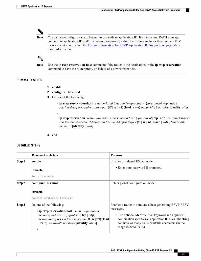
You can also configure a static listener to use with an application ID. If an incoming PATH messagecontains an application ID and/or a preemption priority value, the listener includes them in the RESVmessage sent in reply. See the Feature Information for RSVP Application ID Support, on page 50formore information.
Note
Use the ip rsvp reservation-host command if the router is the destination, or the ip rsvp reservationcommand to have the router proxy on behalf of a downstream host.
Note
SUMMARY STEPS
1. enable2. configure terminal3. Do one of the following:
• ip rsvp reservation-host session-ip-address sender-ip-address {ip-protocol| tcp | udp}session-dest-port sender-source-port{ff | se | wf}{load | rate} bandwidth burst-size[identity alias]
•• ip rsvp reservation session-ip-address sender-ip-address {ip-protocol | tcp | udp} session-dest-portsender-source-port next-hop-ip-address next-hop-interface{ff | se | wf}{load | rate} bandwidthburst-size[identity alias]
4. end
DETAILED STEPS
PurposeCommand or Action
Enables privileged EXEC mode.enableStep 1
Example:
Router> enable
• Enter your password if prompted.
Enters global configuration mode.configure terminal
Example:
Router# configure terminal
Step 2
Enables a router to simulate a host generating RSVP RESVmessages.
Do one of the following:Step 3
• ip rsvp reservation-host session-ip-addresssender-ip-address {ip-protocol| tcp | udp} • The optional identity alias keyword and argument
combination specifies an application ID alias. The stringsession-dest-port sender-source-port{ff | se |wf}{load| rate} bandwidth burst-size[identity alias] can have as many as 64 printable characters (in the
range 0x20 to 0x7E).•
QoS: RSVP Configuration Guide, Cisco IOS XE Release 3S 41
RSVP Application ID SupportConfiguring RSVP Application ID for Non-RSVP-Aware Software Programs

PurposeCommand or Action
If you use the " " or ? character as part of the aliasstring itself, you must type the CTRL-V keysequence before entering the embedded " " or ?character. The alias is never transmitted to otherrouters.
Note
Use the ip rsvp reservation-host command if therouter is the destination or the ip rsvp reservationcommand to have the router proxy on behalf of adownstream host.
Note
• ip rsvp reservation session-ip-addresssender-ip-address {ip-protocol | tcp | udp}session-dest-port sender-source-portnext-hop-ip-address next-hop-interface{ff | se |wf}{load | rate} bandwidth burst-size[identity alias]
Example:
Router(config)# ip rsvp reservation-host 10.1.1.110.30.1.4 udp 20 30 se load 100 60 identityrsvp-voice
Example:
Example:
Router(config)# ip rsvp reservation 10.1.1.10.0.0.0 udp 20 0 172.16.4.1 Ethernet1 wf rate 35065 identity xyz
Exits global configuration mode and returns to privilegedEXEC mode.
end
Example:
Router(config)# end
Step 4
Verifying the RSVP Application ID Support Configuration
You can use the following commands in user EXEC or privileged EXEC mode, in any order.Note
QoS: RSVP Configuration Guide, Cisco IOS XE Release 3S42
RSVP Application ID SupportVerifying the RSVP Application ID Support Configuration
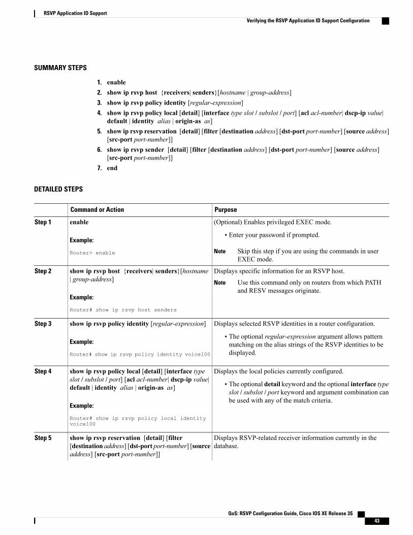
SUMMARY STEPS
1. enable2. show ip rsvp host {receivers| senders}[hostname | group-address]3. show ip rsvp policy identity [regular-expression]4. show ip rsvp policy local [detail] [interface type slot / subslot / port] [acl acl-number| dscp-ip value|
default | identity alias | origin-as as]5. show ip rsvp reservation [detail] [filter [destination address] [dst-port port-number] [source address]
[src-port port-number]]6. show ip rsvp sender [detail] [filter [destination address] [dst-port port-number] [source address]
[src-port port-number]]7. end
DETAILED STEPS
PurposeCommand or Action
(Optional) Enables privileged EXEC mode.enableStep 1
Example:
Router> enable
• Enter your password if prompted.
Skip this step if you are using the commands in userEXEC mode.
Note
Displays specific information for an RSVP host.show ip rsvp host {receivers| senders}[hostname| group-address]
Step 2
Use this command only on routers from which PATHand RESV messages originate.
Note
Example:
Router# show ip rsvp host senders
Displays selected RSVP identities in a router configuration.show ip rsvp policy identity [regular-expression]Step 3
Example:
Router# show ip rsvp policy identity voice100
• The optional regular-expression argument allows patternmatching on the alias strings of the RSVP identities to bedisplayed.
Displays the local policies currently configured.show ip rsvp policy local [detail] [interface typeslot / subslot / port] [acl acl-number| dscp-ip value|default | identity alias | origin-as as]
Step 4
• The optional detail keyword and the optional interface typeslot / subslot / port keyword and argument combination canbe used with any of the match criteria.
Example:
Router# show ip rsvp policy local identityvoice100
Displays RSVP-related receiver information currently in thedatabase.
show ip rsvp reservation [detail] [filter[destination address] [dst-port port-number] [sourceaddress] [src-port port-number]]
Step 5
QoS: RSVP Configuration Guide, Cisco IOS XE Release 3S 43
RSVP Application ID SupportVerifying the RSVP Application ID Support Configuration

PurposeCommand or Action
• The optional detail keyword displays additional output withinformation about where the policy originated and whichapplication ID was signaled in the RESV message.
Example:
Router# show ip rsvp reservation detail
Displays RSVP PATH-related sender information currently in thedatabase.
show ip rsvp sender [detail] [filter [destinationaddress] [dst-port port-number] [source address][src-port port-number]]
Step 6
• The optional detail keyword displays additional output withinformation that includes which application IDwas signaledin the PATH message.Example:
Router# show ip rsvp sender detail
Exits privileged EXEC mode and returns to user EXEC mode.end
Example:
Router# end
Step 7
Configuration Examples for RSVP Application ID Support
Example Configuring RSVP Application ID SupportThe configurations for four-router network shown in the figure below are in the following sections:
Figure 3: Sample Network with Application Identities and Local Policies
Configuring a Proxy Receiver on R4The following example configures R4 with a proxy receiver to create an RESV message to match the PATHmessage for the destination 10.0.0.7:
Device# configure terminalEnter configuration commands, one per line. End with CNTL/Z.Device(config)# ip rsvp listener 10.0.0.7 any any reply
Device(config)# end
QoS: RSVP Configuration Guide, Cisco IOS XE Release 3S44
RSVP Application ID SupportConfiguration Examples for RSVP Application ID Support
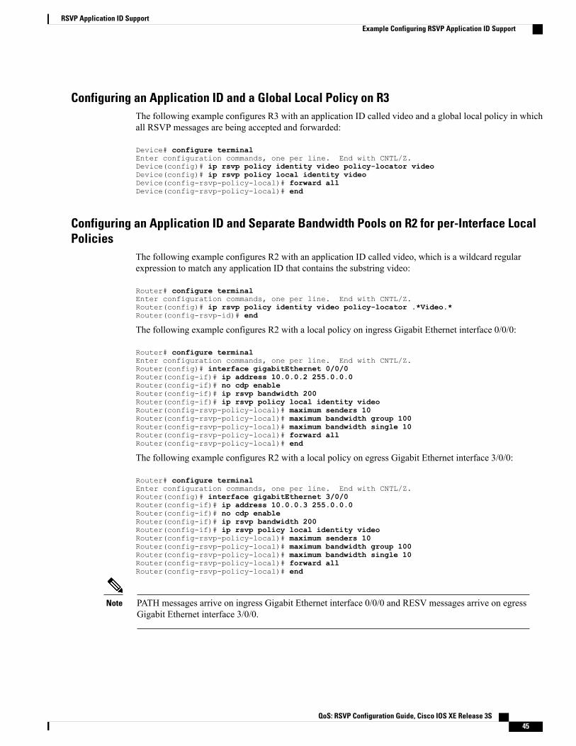
Configuring an Application ID and a Global Local Policy on R3The following example configures R3 with an application ID called video and a global local policy in whichall RSVP messages are being accepted and forwarded:
Device# configure terminalEnter configuration commands, one per line. End with CNTL/Z.Device(config)# ip rsvp policy identity video policy-locator videoDevice(config)# ip rsvp policy local identity videoDevice(config-rsvp-policy-local)# forward allDevice(config-rsvp-policy-local)# end
Configuring an Application ID and Separate Bandwidth Pools on R2 for per-Interface LocalPolicies
The following example configures R2 with an application ID called video, which is a wildcard regularexpression to match any application ID that contains the substring video:
Router# configure terminalEnter configuration commands, one per line. End with CNTL/Z.Router(config)# ip rsvp policy identity video policy-locator .*Video.*Router(config-rsvp-id)# end
The following example configures R2 with a local policy on ingress Gigabit Ethernet interface 0/0/0:
Router# configure terminalEnter configuration commands, one per line. End with CNTL/Z.Router(config)# interface gigabitEthernet 0/0/0Router(config-if)# ip address 10.0.0.2 255.0.0.0Router(config-if)# no cdp enableRouter(config-if)# ip rsvp bandwidth 200Router(config-if)# ip rsvp policy local identity videoRouter(config-rsvp-policy-local)# maximum senders 10Router(config-rsvp-policy-local)# maximum bandwidth group 100Router(config-rsvp-policy-local)# maximum bandwidth single 10Router(config-rsvp-policy-local)# forward allRouter(config-rsvp-policy-local)# end
The following example configures R2 with a local policy on egress Gigabit Ethernet interface 3/0/0:
Router# configure terminalEnter configuration commands, one per line. End with CNTL/Z.Router(config)# interface gigabitEthernet 3/0/0Router(config-if)# ip address 10.0.0.3 255.0.0.0Router(config-if)# no cdp enableRouter(config-if)# ip rsvp bandwidth 200Router(config-if)# ip rsvp policy local identity videoRouter(config-rsvp-policy-local)# maximum senders 10Router(config-rsvp-policy-local)# maximum bandwidth group 100Router(config-rsvp-policy-local)# maximum bandwidth single 10Router(config-rsvp-policy-local)# forward allRouter(config-rsvp-policy-local)# end
PATH messages arrive on ingress Gigabit Ethernet interface 0/0/0 and RESV messages arrive on egressGigabit Ethernet interface 3/0/0.
Note
QoS: RSVP Configuration Guide, Cisco IOS XE Release 3S 45
RSVP Application ID SupportExample Configuring RSVP Application ID Support

Configuring an Application ID and a Static Reservation from R1 to R4The following example configures R1 with an application ID called video and initiates a host generating aPATH message with that application ID:
Device# configure terminalEnter configuration commands, one per line. End with CNTL/Z.Device(config)# ip rsvp policy identity video policy-locator "GUID=www.cisco.com, APP=Video,VER=1.0"Device(config)# ip rsvp sender-host 10.0.0.7 10.0.0.1 udp 1 1 10 10 identity videoDevice(config)# end
Example Verifying RSVP Application ID Support
Verifying the Application ID and the Global Local Policy on R3The following example verifies that a global local policy has been configured on R3 with an application IDcalled Video:
Router# show ip rsvp policy local detailGlobal:Policy for ID(s): VideoPreemption Scope: Unrestricted.Local Override: Disabled.Fast ReRoute: Accept.Handle: 23000404.
Accept ForwardPath: Yes YesResv: Yes YesPathError: Yes YesResvError: Yes Yes
Setup Priority Hold PriorityTE: N/A N/ANon-TE: N/A N/A
Current LimitSenders: 1 N/AReceivers: 1 N/AConversations: 1 N/AGroup bandwidth (bps): 10K N/APer-flow b/w (bps): N/A N/A
Generic policy settings:Default policy: Accept allPreemption: Disabled
Verifying the Application ID and the per-Interface Local Policies on R2The following example verifies that an application ID called Video has been created on R2:
Router# show ip rsvp policy identityAlias: VideoType: Application IDLocator: .*Video.*
QoS: RSVP Configuration Guide, Cisco IOS XE Release 3S46
RSVP Application ID SupportExample Verifying RSVP Application ID Support

The following example verifies that per-interface local policies have been created on Gigabit Ethernet interface0/0/0 and Gigabit Ethernet interface 3/0/0 on R2:
Router# show ip rsvp policy local detailgigabitEthernet 0/0/0:Policy for ID(s): VideoPreemption Scope: Unrestricted.Local Override: Disabled.Fast ReRoute: Accept.Handle: 26000404.
Accept ForwardPath: Yes YesResv: Yes YesPathError: Yes YesResvError: Yes Yes
Setup Priority Hold PriorityTE: N/A N/ANon-TE: N/A N/A
Current LimitSenders: 1 10Receivers: 0 N/AConversations: 0 N/AGroup bandwidth (bps): 0 100KPer-flow b/w (bps): N/A 10K
giabitEthernet 3/0/0:Policy for ID(s): VideoPreemption Scope: Unrestricted.Local Override: Disabled.Fast ReRoute: Accept.Handle: 5A00040A.
Accept ForwardPath: Yes YesResv: Yes YesPathError: Yes YesResvError: Yes Yes
Setup Priority Hold PriorityTE: N/A N/ANon-TE: N/A N/A
Current LimitSenders: 0 10Receivers: 1 N/AConversations: 1 N/AGroup bandwidth (bps): 10K 100KPer-flow b/w (bps): N/A 10K
Generic policy settings:Default policy: Accept allPreemption: Disabled
Notice in the display that the ingress interface has only its senders counter incremented because the PATHmessage is checked there. However, the egress interface has its receivers, conversations, and groupbandwidth counters incremented because the reservation is checked on the incoming interface, which isthe egress interface on R2.
Note
Verifying the Application ID and the Reservation on R1The following example verifies that a PATH message containing the application ID called Video has beencreated on R1:
Router# show ip rsvp sender detailPATH Session address: 10.0.0.7, port: 1. Protocol: UDPSender address: 10.0.0.1, port: 1
Inbound from: 10.0.0.1 on interface:
QoS: RSVP Configuration Guide, Cisco IOS XE Release 3S 47
RSVP Application ID SupportExample Verifying RSVP Application ID Support
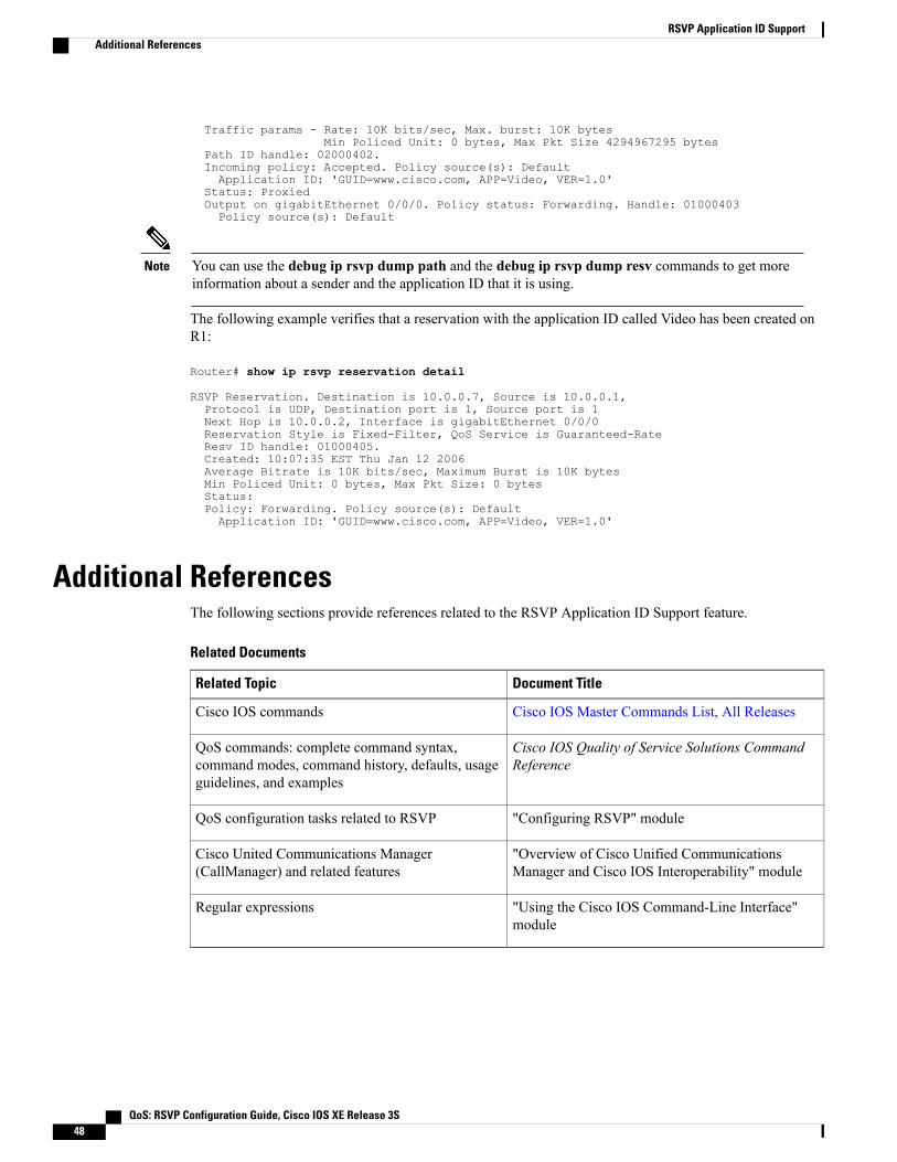
Traffic params - Rate: 10K bits/sec, Max. burst: 10K bytesMin Policed Unit: 0 bytes, Max Pkt Size 4294967295 bytes
Path ID handle: 02000402.Incoming policy: Accepted. Policy source(s): DefaultApplication ID: 'GUID=www.cisco.com, APP=Video, VER=1.0'
Status: ProxiedOutput on gigabitEthernet 0/0/0. Policy status: Forwarding. Handle: 01000403Policy source(s): Default
You can use the debug ip rsvp dump path and the debug ip rsvp dump resv commands to get moreinformation about a sender and the application ID that it is using.
Note
The following example verifies that a reservation with the application ID called Video has been created onR1:
Router# show ip rsvp reservation detail
RSVP Reservation. Destination is 10.0.0.7, Source is 10.0.0.1,Protocol is UDP, Destination port is 1, Source port is 1Next Hop is 10.0.0.2, Interface is gigabitEthernet 0/0/0Reservation Style is Fixed-Filter, QoS Service is Guaranteed-RateResv ID handle: 01000405.Created: 10:07:35 EST Thu Jan 12 2006Average Bitrate is 10K bits/sec, Maximum Burst is 10K bytesMin Policed Unit: 0 bytes, Max Pkt Size: 0 bytesStatus:Policy: Forwarding. Policy source(s): DefaultApplication ID: 'GUID=www.cisco.com, APP=Video, VER=1.0'
Additional ReferencesThe following sections provide references related to the RSVP Application ID Support feature.
Related Documents
Document TitleRelated Topic
Cisco IOS Master Commands List, All ReleasesCisco IOS commands
Cisco IOS Quality of Service Solutions CommandReference
QoS commands: complete command syntax,command modes, command history, defaults, usageguidelines, and examples
"Configuring RSVP" moduleQoS configuration tasks related to RSVP
"Overview of Cisco Unified CommunicationsManager and Cisco IOS Interoperability" module
Cisco United Communications Manager(CallManager) and related features
"Using the Cisco IOS Command-Line Interface"module
Regular expressions
QoS: RSVP Configuration Guide, Cisco IOS XE Release 3S48
RSVP Application ID SupportAdditional References
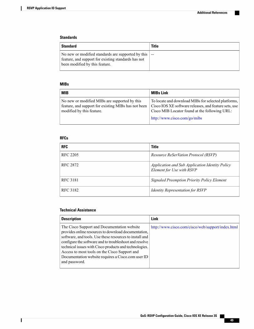
Standards
TitleStandard
--No new or modified standards are supported by thisfeature, and support for existing standards has notbeen modified by this feature.
MIBs
MIBs LinkMIB
To locate and downloadMIBs for selected platforms,Cisco IOSXE software releases, and feature sets, useCisco MIB Locator found at the following URL:
http://www.cisco.com/go/mibs
No new or modified MIBs are supported by thisfeature, and support for existing MIBs has not beenmodified by this feature.
RFCs
TitleRFC
Resource ReSerVation Protocol (RSVP)RFC 2205
Application and Sub Application Identity PolicyElement for Use with RSVP
RFC 2872
Signaled Preemption Priority Policy ElementRFC 3181
Identity Representation for RSVPRFC 3182
Technical Assistance
LinkDescription
http://www.cisco.com/cisco/web/support/index.htmlThe Cisco Support and Documentation websiteprovides online resources to download documentation,software, and tools. Use these resources to install andconfigure the software and to troubleshoot and resolvetechnical issues with Cisco products and technologies.Access to most tools on the Cisco Support andDocumentation website requires a Cisco.com user IDand password.
QoS: RSVP Configuration Guide, Cisco IOS XE Release 3S 49
RSVP Application ID SupportAdditional References

Feature Information for RSVP Application ID SupportThe following table provides release information about the feature or features described in this module. Thistable lists only the software release that introduced support for a given feature in a given software releasetrain. Unless noted otherwise, subsequent releases of that software release train also support that feature.
Use Cisco Feature Navigator to find information about platform support and Cisco software image support.To access Cisco Feature Navigator, go to www.cisco.com/go/cfn. An account on Cisco.com is not required.
Table 2: Feature Information for RSVP Application ID Support
Feature InformationReleasesFeature Name
The RSVPApplication ID Supportfeature introducesapplication-specific reservations,which enhance the granularity forlocal policy-match criteria so thatyou can manage QoS on the basisof application type.
The following commands wereintroduced or modified: ip rsvplistener, ip rsvp policy identity,ip rsvp policy local, ip rsvpreservation, ip rsvpreservation-host, ip rsvp sender,ip rsvp sender-host,maximum(local policy), show iprsvp host, show ip rsvp policyidentity, show ip rsvp policylocal.
In Cisco IOS XE Release 3.8S,support was added for the CiscoASR 903 Router.
Cisco IOS XE Release 2.6
Cisco IOS XE Release 3.8S
RSVP Application ID Support
GlossaryQoS --quality of service. A measure of performance for a transmission system that reflects its transmissionquality and service availability.
RSVP --Resource Reservation Protocol. A protocol that supports the reservation of resources across an IPnetwork. Applications running on IP end systems can use RSVP to indicate to other nodes the nature (bandwidth,jitter, maximum burst, and so on) of the packet streams that they want to receive.
RSVP Agent --Implements a Resource Reservation Protocol (RSVP) agent on Cisco IOS voice gatewaysthat support Unified CM.
QoS: RSVP Configuration Guide, Cisco IOS XE Release 3S50
RSVP Application ID SupportFeature Information for RSVP Application ID Support

Unified Communcations Manager (CM)--The software-based, call-processing component of the Cisco IPtelephony solution. The software extends enterprise telephony features and functions to packet telephonynetwork devices such as IP phones, media processing devices, voice-over-IP (VoIP) gateways, and multimediaapplications.
QoS: RSVP Configuration Guide, Cisco IOS XE Release 3S 51
RSVP Application ID SupportGlossary

QoS: RSVP Configuration Guide, Cisco IOS XE Release 3S52
RSVP Application ID SupportGlossary

C H A P T E R 3RSVP Fast Local Repair
The RSVP Fast Local Repair feature provides quick adaptation to routing changes occurring in global andVirtual Routing and Forwarding (VRF) domains, without the overhead of the refresh period to guaranteethe quality of service (QoS) for data flows. With fast local repair (FLR), Resource Reservation Protocol(RSVP) speeds up its response to routing changes from 30 seconds to a few seconds.
• Finding Feature Information, page 53
• Prerequisites for RSVP FLR, page 53
• Restrictions for RSVP FLR, page 54
• Information About RSVP FLR, page 54
• How to Configure RSVP FLR, page 55
• Configuration Examples for RSVP FLR, page 60
• Additional References, page 63
• Feature Information for RSVP FLR, page 64
• Glossary, page 65
Finding Feature InformationYour software release may not support all the features documented in this module. For the latest caveats andfeature information, see Bug Search Tool and the release notes for your platform and software release. Tofind information about the features documented in this module, and to see a list of the releases in which eachfeature is supported, see the feature information table at the end of this module.
Use Cisco Feature Navigator to find information about platform support and Cisco software image support.To access Cisco Feature Navigator, go to www.cisco.com/go/cfn. An account on Cisco.com is not required.
Prerequisites for RSVP FLRYou must configure RSVP on one or more interfaces on at least two neighboring devices that share a linkwithin the network.
QoS: RSVP Configuration Guide, Cisco IOS XE Release 3S 53

Restrictions for RSVP FLR• RSVP FLR applies only when RSVP is used to set up resource reservations for IPv4 unicast flows; IPv4multicast flows are not supported.
• RSVP FLR does not apply to traffic engineering (TE) tunnels and, therefore, does not affect TE sessions.
• RSVP FLR does not support message bundling.
Information About RSVP FLR
Feature Overview of RSVP FLRRSVP FLR provides for dynamic adaptation when routing changes occur in global or VRF routing domains.When a route changes, the next PATH and RESV message refreshes establish path and reservation statesalong the new route. Depending on the configured refresh interval, this reroute happens in tens of seconds.However, during this time, the QoS of flows is not guaranteed because congestion may occur while datapackets travel over links where reservations are not yet in place.
In order to provide faster adaptation to routing changes, without the overhead of a refresh period, RSVPregisters with the Routing Information Base (RIB) and receives notifications when routes change, therebytriggering state refreshes for the affected destinations. These triggered refreshes use the new route informationand, as a result, install reservations over the new path.
When routes change, RSVP has to reroute all affected paths and reservations. Without FLR, the reroutehappens when refresh timers expire for the path states. With real-time applications such as VoIP and videoon demand (VoD), the requirement changes and the reroute must happen, within three seconds from thetriggering event such as link down or link up.
The figure below illustrates the FLR process.
Figure 4: Overview of RSVP FLR
Initial RSVP states are installed for an IPv4 unicast flow over Routers A, B, C, D, and E. Router A is thesource or headend, and Router E is the destination or tailend. The data packets are destined to an address ofRouter E. Assume that a route change occurs, and the new path taken by the data packets is from Router Ato Router B to Router F to Router D to Router E; therefore, the old and new paths differ on the segments
QoS: RSVP Configuration Guide, Cisco IOS XE Release 3S54
RSVP Fast Local RepairRestrictions for RSVP FLR
between Routers B and D. The Router B to Router C to Router D segment is the old segment, and the RouterB to Router F to Router D segment is the new segment.
A route may change because of a link or node failure, or if a better path becomes available.
RSVP at Router B detects that the route change affects the RSVP flow and initiates the FLR procedure. Thenode that initiates an FLR repair procedure, Router B in the figure above, is the point of local repair (PLR).The node where the new and old segments meet, Router D in the figure above, is the merge point (MP). Theinterfaces at the PLR and the MP that are part of the old segment are the old interfaces, and the interfaces thatare part of the new segment are the new interfaces.
If a route has changed because of a failure, the PLR may not be the node that detects the failure. For example,it is possible that the link from Router C to Router D fails, and although Router C detects the failure, the routechange at Router B is the trigger for the FLR procedure. Router C, in this case, is also referred to as the nodethat detects the failure.
The support for FLR in VRF domains means that RSVP can get a route change notification, even if there isa route change in any VRF domains, because RSVP FLR was previously supported only in the global routingdomain.
Benefits of RSVP FLR
Faster Response Time to Routing Changes
FLR reduces the time that it takes for RSVP to determine that a physical link has gone down and that the datapackets have been rerouted. Without FLR, RSVP may not recognize the link failure for 30 seconds when allof the sessions are impacted by having too much traffic for the available bandwidth. With FLR, this time canbe significantly reduced to a few seconds.
After detecting the failure, RSVP recomputes the admission control across the new link. If the rerouted trafficfits on the new link, RSVP reserves the bandwidth and guarantees the QoS of the new traffic.
If admission control fails on the new route, RSVP does not explicate tear down the flow, but instead sends aRESVERRORmessage toward the receiver. If a proxy receiver is running, then RSVP sends a PATHERRORmessage toward the headend, in response to the RESVERROR message, indicating the admission failure. Inboth cases, with and without a proxy receiver, the application tears down the failed session either at the headendor at the final destination.
Until this happens, the data packets belonging to this session still flow over the rerouted segment althoughadmission has failed and QoS is affected.
The support of FLR in VRF domains means that if there is a route change in any routing domain, RSVP canuse FLR to adapt to the routing change, because RSVP FLR was previously supported only in the globalrouting domain.
How to Configure RSVP FLRYou can configure the RSVP FLR parameters in any order that you want.
QoS: RSVP Configuration Guide, Cisco IOS XE Release 3S 55
RSVP Fast Local RepairBenefits of RSVP FLR
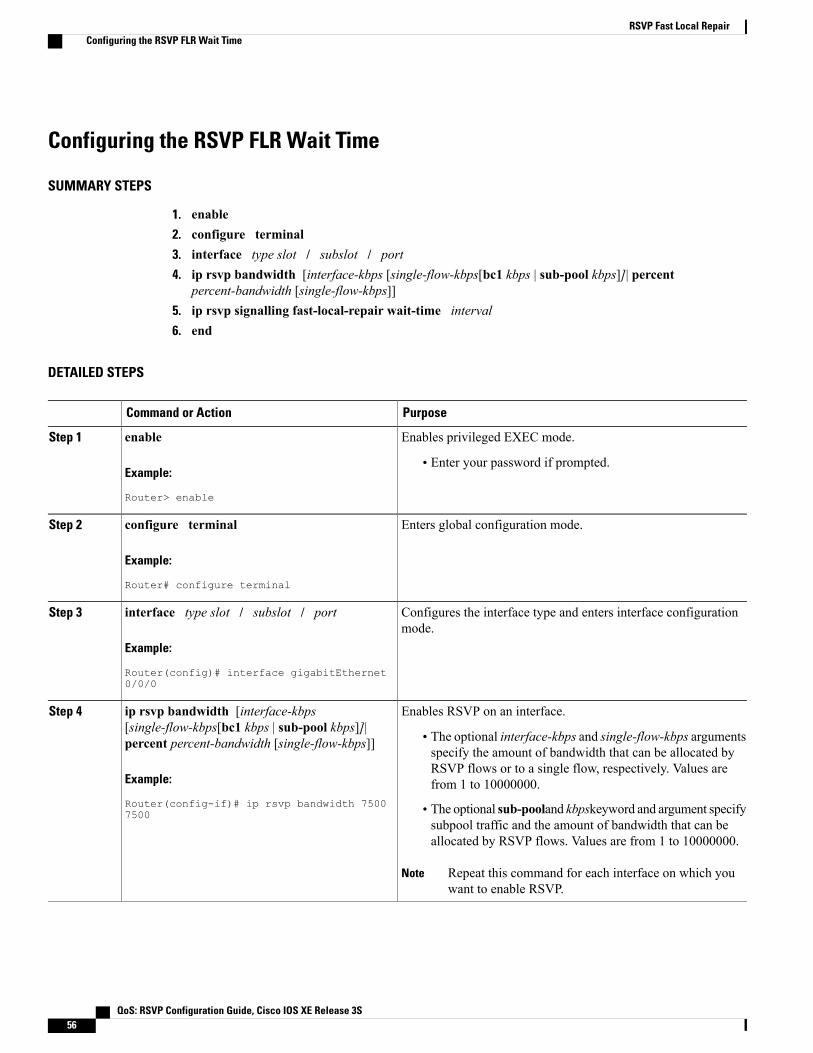
Configuring the RSVP FLR Wait Time
SUMMARY STEPS
1. enable2. configure terminal3. interface type slot / subslot / port4. ip rsvp bandwidth [interface-kbps [single-flow-kbps[bc1 kbps | sub-pool kbps]]| percent
percent-bandwidth [single-flow-kbps]]5. ip rsvp signalling fast-local-repair wait-time interval6. end
DETAILED STEPS
PurposeCommand or Action
Enables privileged EXEC mode.enableStep 1
Example:
Router> enable
• Enter your password if prompted.
Enters global configuration mode.configure terminal
Example:
Router# configure terminal
Step 2
Configures the interface type and enters interface configurationmode.
interface type slot / subslot / port
Example:
Router(config)# interface gigabitEthernet0/0/0
Step 3
Enables RSVP on an interface.ip rsvp bandwidth [interface-kbps[single-flow-kbps[bc1 kbps | sub-pool kbps]]|percent percent-bandwidth [single-flow-kbps]]
Step 4
• The optional interface-kbps and single-flow-kbps argumentsspecify the amount of bandwidth that can be allocated by
Example:
Router(config-if)# ip rsvp bandwidth 75007500
RSVP flows or to a single flow, respectively. Values arefrom 1 to 10000000.
• The optional sub-pooland kbpskeyword and argument specifysubpool traffic and the amount of bandwidth that can beallocated by RSVP flows. Values are from 1 to 10000000.
Repeat this command for each interface on which youwant to enable RSVP.
Note
QoS: RSVP Configuration Guide, Cisco IOS XE Release 3S56
RSVP Fast Local RepairConfiguring the RSVP FLR Wait Time

PurposeCommand or Action
Configures the delay that RSVP uses before starting an FLRprocedure.
ip rsvp signalling fast-local-repair wait-timeinterval
Step 5
Example:
Router(config-if)# ip rsvp signallingfast-local-repair wait-time 100
• Values for the interval argument are 1 to 2500 milliseconds(ms); the default is 0.
(Optional) Returns to privileged EXEC mode.end
Example:
Router(config-if)# end
Step 6
Configuring the RSVP FLR Repair Rate
SUMMARY STEPS
1. enable2. configure terminal3. ip rsvp signalling fast-local-repair rate rate4. exit
DETAILED STEPS
PurposeCommand or Action
Enables privileged EXEC mode.enableStep 1
Example:
Router> enable
• Enter your password if prompted.
Enters global configuration mode.configure terminal
Example:
Router# configure terminal
Step 2
QoS: RSVP Configuration Guide, Cisco IOS XE Release 3S 57
RSVP Fast Local RepairConfiguring the RSVP FLR Repair Rate
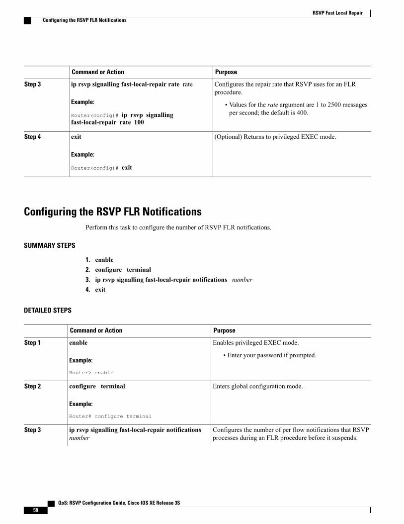
PurposeCommand or Action
Configures the repair rate that RSVP uses for an FLRprocedure.
ip rsvp signalling fast-local-repair rate rate
Example:
Router(config)# ip rsvp signallingfast-local-repair rate 100
Step 3
• Values for the rate argument are 1 to 2500 messagesper second; the default is 400.
(Optional) Returns to privileged EXEC mode.exit
Example:
Router(config)# exit
Step 4
Configuring the RSVP FLR NotificationsPerform this task to configure the number of RSVP FLR notifications.
SUMMARY STEPS
1. enable2. configure terminal3. ip rsvp signalling fast-local-repair notifications number4. exit
DETAILED STEPS
PurposeCommand or Action
Enables privileged EXEC mode.enableStep 1
Example:
Router> enable
• Enter your password if prompted.
Enters global configuration mode.configure terminal
Example:
Router# configure terminal
Step 2
Configures the number of per flow notifications that RSVPprocesses during an FLR procedure before it suspends.
ip rsvp signalling fast-local-repair notificationsnumber
Step 3
QoS: RSVP Configuration Guide, Cisco IOS XE Release 3S58
RSVP Fast Local RepairConfiguring the RSVP FLR Notifications
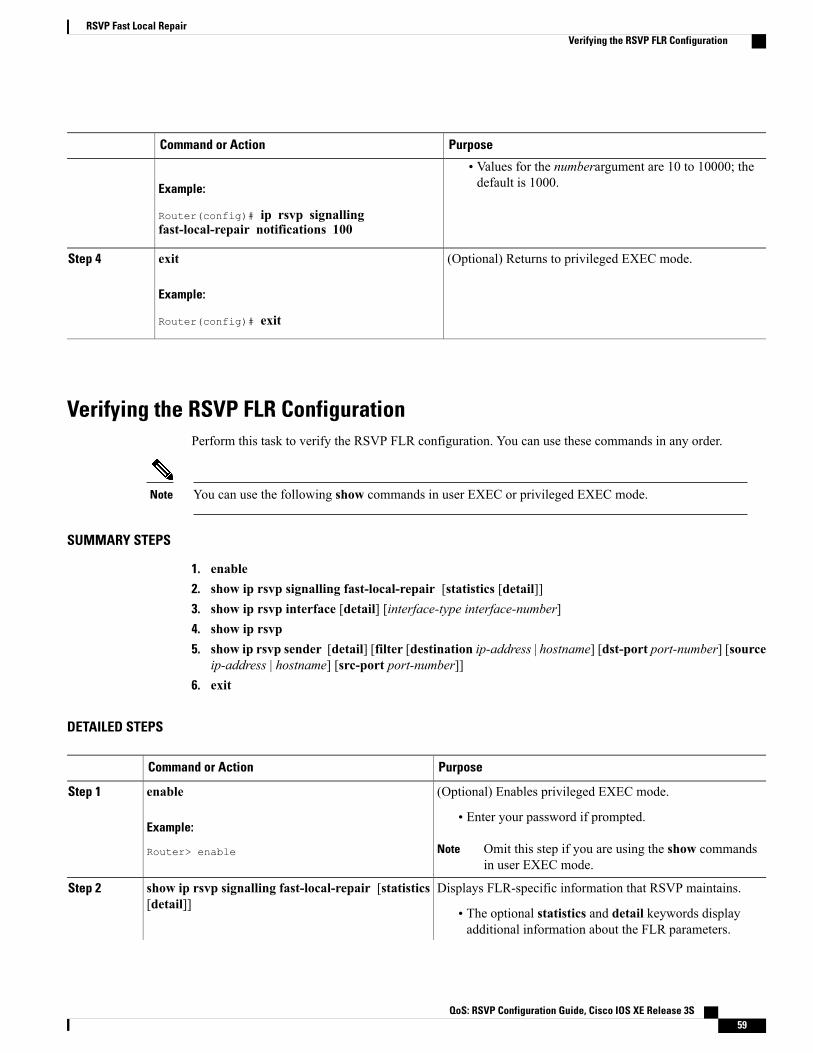
PurposeCommand or Action
Example:
Router(config)# ip rsvp signallingfast-local-repair notifications 100
• Values for the numberargument are 10 to 10000; thedefault is 1000.
(Optional) Returns to privileged EXEC mode.exit
Example:
Router(config)# exit
Step 4
Verifying the RSVP FLR ConfigurationPerform this task to verify the RSVP FLR configuration. You can use these commands in any order.
You can use the following show commands in user EXEC or privileged EXEC mode.Note
SUMMARY STEPS
1. enable2. show ip rsvp signalling fast-local-repair [statistics [detail]]3. show ip rsvp interface [detail] [interface-type interface-number]4. show ip rsvp5. show ip rsvp sender [detail] [filter [destination ip-address | hostname] [dst-port port-number] [source
ip-address | hostname] [src-port port-number]]6. exit
DETAILED STEPS
PurposeCommand or Action
(Optional) Enables privileged EXEC mode.enableStep 1
Example:
Router> enable
• Enter your password if prompted.
Omit this step if you are using the show commandsin user EXEC mode.
Note
Displays FLR-specific information that RSVP maintains.show ip rsvp signalling fast-local-repair [statistics[detail]]
Step 2
• The optional statistics and detail keywords displayadditional information about the FLR parameters.
QoS: RSVP Configuration Guide, Cisco IOS XE Release 3S 59
RSVP Fast Local RepairVerifying the RSVP FLR Configuration

PurposeCommand or Action
Example:
Router# show ip rsvp signallingfast-local-repair statistics detail
Displays RSVP-related information.show ip rsvp interface [detail] [interface-typeinterface-number]
Step 3
• The optional detail keyword displays additionalinformation including FLR parameters.
Example:
Router# show ip rsvp interface gigabitethernet0/0/0
Displays general RSVP-related information.show ip rsvp
Example:
Router# show ip rsvp
Step 4
Displays RSVP PATH-related sender information currently inthe database.
show ip rsvp sender [detail] [filter [destinationip-address | hostname] [dst-port port-number] [sourceip-address | hostname] [src-port port-number]]
Step 5
• The optional detail keyword displays additional outputincluding the FLR parameters.
Example:
Router# show ip rsvp sender detail
(Optional) Exits privileged EXEC mode and returns to userEXEC mode.
exit
Example:
Router# exit
Step 6
Configuration Examples for RSVP FLR
Example Configuring RSVP FLRThe configuration options for RSVP FLR are the following:
•Wait time
• Number of notifications
• Repair rate
QoS: RSVP Configuration Guide, Cisco IOS XE Release 3S60
RSVP Fast Local RepairConfiguration Examples for RSVP FLR

You can configure these options in any order.Note
Configuring the Wait Time
The following example configures gigabitEthernet interface 0/0/0 with a bandwidth of 200 kbps and a waittime of 1000 ms:
Router# configure terminalEnter configuration commands, one per line. End with CNTL/Z.Router(config)# interface gigabitethernet 0/0/0Router(config-if)# ip rsvp bandwidth 200Router(config-if)# ip rsvp signalling fast-local-repair wait-time 1000Router(config-if)# end
Configuring the Number of Notifications
The following example configures the number of flows that are repaired before suspending to 100:
Router# configure terminalEnter configuration commands, one per line. End with CNTL/Z.Router(config)# ip rsvp signalling fast-local-repair notifications 100Router(config)# exit
Configuring the Repair Rate
The following example configures a repair rate of 100 messages per second:
Router# configure terminalEnter configuration commands, one per line. End with CNTL/Z.Router(config)# ip rsvp signalling fast-local-repair rate 100Router(config)# exit
Example Verifying the RSVP FLR Configuration
Verifying the Details for FLR ProceduresThe following example displays detailed information about FLR procedures:
Router# show ip rsvp signalling fast-local-repair statistics detailFast Local Repair: enabledMax repair rate (paths/sec): 10Max processed (paths/run): 10
FLR Statistics:FLR 1: DONEStart Time: 05:18:54 IST Mon Nov 5 2007Number of PSBs repaired: 2Used Repair Rate (msgs/sec): 10RIB notification processing time: 0(us).Time of last PSB refresh: 5025(ms).Time of last Resv received: 6086(ms).Time of last Perr received: 0(us).Suspend count: 0FLR Pacing Unit: 100 msec.Affected neighbors:Nbr Address Interface Relative Delay Values (msec) VRF
QoS: RSVP Configuration Guide, Cisco IOS XE Release 3S 61
RSVP Fast Local RepairExample Verifying the RSVP FLR Configuration

10.1.2.12 Et0/3 [5000 ,..., 5000 ] vrf110.1.2.12 Et1/3 [5000 ,..., 5000 ] vrf2
Verifying Configuration Details for a Specific InterfaceThe following example from the show ip rsvp interface detail command displays detailed information,including FLR, for the gigabitEthernet 0/0/0 interface:
Router# show ip rsvp interface detail gigabitethernet 0/0/0Et1/0:RSVP: EnabledInterface State: UpBandwidth:Curr allocated: 9K bits/secMax. allowed (total): 300K bits/secMax. allowed (per flow): 300K bits/secMax. allowed for LSP tunnels using sub-pools (pool 1): 0 bits/secSet aside by policy (total): 0 bits/sec
Traffic Control:RSVP Data Packet Classification is ON via CEF callbacks
Signalling:DSCP value used in RSVP msgs: 0x30Number of refresh intervals to enforce blockade state: 4
FLR Wait Time (IPv4 flows):Repair is delayed by 1000 msec.
Authentication: disabledKey chain: <none>Type: md5Window size: 1Challenge: disabled
Hello Extension:State: Disabled
Verifying Configuration Details Before During and After an FLR ProcedureThe following is sample output from the showiprsvpsenderdetail command before an FLR procedure hasoccurred:
Router# show ip rsvp sender detailPATH:
Destination 192.168.101.21, Protocol_Id 17, Don't Police , DstPort 1Sender address: 10.10.10.10, port: 1Path refreshes:arriving: from PHOP 172.3.31.34 on Et0/0 every 30000 msecs
Traffic params - Rate: 9K bits/sec, Max. burst: 9K bytesMin Policed Unit: 0 bytes, Max Pkt Size 2147483647 bytes
Path ID handle: 01000401.Incoming policy: Accepted. Policy source(s): DefaultStatus:Output on gigabitEthernet 0/0/0. Policy status: Forwarding. Handle: 02000400Policy source(s): Default
Path FLR: Never repaired
The following is sample output from the showiprsvpsenderdetail command at the PLR during an FLRprocedure:
Router# show ip rsvp sender detailPATH:
Destination 192.168.101.21, Protocol_Id 17, Don't Police , DstPort 1Sender address: 10.10.10.10, port: 1Path refreshes:arriving: from PHOP 172.16.31.34 on Et0/0 every 30000 msecs
Traffic params - Rate: 9K bits/sec, Max. burst: 9K bytesMin Policed Unit: 0 bytes, Max Pkt Size 2147483647 bytes
Path ID handle: 01000401.
QoS: RSVP Configuration Guide, Cisco IOS XE Release 3S62
RSVP Fast Local RepairExample Verifying the RSVP FLR Configuration

Incoming policy: Accepted. Policy source(s): DefaultStatus:Path FLR: PSB is currently being repaired...try laterPLR - Old Segments: 1Output on Ethernet1/0, nhop 172.5.36.34Time before expiry: 2 refreshesPolicy status: Forwarding. Handle: 02000400
Policy source(s): Default
The following is sample output from the showiprsvpsenderdetail command at the MP during an FLRprocedure:
Router# show ip rsvp sender detailPATH:
Destination 192.168.101.21, Protocol_Id 17, Don't Police , DstPort 1Sender address: 10.10.10.10, port: 1Path refreshes:arriving: from PHOP 172.16.37.35 on Et1/0 every 30000 msecs
Traffic params - Rate: 9K bits/sec, Max. burst: 9K bytesMin Policed Unit: 0 bytes, Max Pkt Size 2147483647 bytes
Path ID handle: 09000406.Incoming policy: Accepted. Policy source(s): DefaultStatus: Proxy-terminatedPath FLR: Never repairedMP - Old Segments: 1Input on Serial2/0, phop 172.16.36.35Time before expiry: 9 refreshes
The following is sample output from the showiprsvpsenderdetail command at the PLR after an FLR procedure:
Router# show ip rsvp sender detailPATH:
Destination 192.168.101.21, Protocol_Id 17, Don't Police , DstPort 1Sender address: 10.10.10.10, port: 1Path refreshes:arriving: from PHOP 172.16.31.34 on Et0/0 every 30000 msecs
Traffic params - Rate: 9K bits/sec, Max. burst: 9K bytesMin Policed Unit: 0 bytes, Max Pkt Size 2147483647 bytes
Path ID handle: 05000401.Incoming policy: Accepted. Policy source(s): DefaultStatus:Output on Serial3/0. Policy status: Forwarding. Handle: 3B000406Policy source(s): Default
Path FLR: Started 12:56:16 EST Thu Nov 16 2006, PSB repaired 532(ms) after.Resv/Perr: Received 992(ms) after.
Additional ReferencesThe following sections provide references related to the Control Plane DSCP Support for RSVP feature.
Related Documents
Document TitleRelated Topic
Cisco IOS Master Commands List, All ReleasesCisco IOS commands
Cisco IOS Quality of Service Solutions CommandReference
RSVP Commands: complete command syntax,command modes, command history, defaults, usageguidelines, and examples
"Quality of Service Overview" moduleQuality of service overview
QoS: RSVP Configuration Guide, Cisco IOS XE Release 3S 63
RSVP Fast Local RepairAdditional References

Standards
TitleStandard
--None
MIBs
MIBs LinkMIB
To locate and downloadMIBs for selected platforms,software releases, and feature sets, use Cisco MIBLocator found at the following URL:
http://www.cisco.com/go/mibs
RFC 2206 (RSVP Management Information Baseusing SMIv2)
RFCs
TitleRFC
Resource Reservation ProtocolRFC 2205
Technical Assistance
LinkDescription
http://www.cisco.com/cisco/web/support/index.htmlThe Cisco Support and Documentation websiteprovides online resources to download documentation,software, and tools. Use these resources to install andconfigure the software and to troubleshoot and resolvetechnical issues with Cisco products and technologies.Access to most tools on the Cisco Support andDocumentation website requires a Cisco.com user IDand password.
Feature Information for RSVP FLRThe following table provides release information about the feature or features described in this module. Thistable lists only the software release that introduced support for a given feature in a given software releasetrain. Unless noted otherwise, subsequent releases of that software release train also support that feature.
Use Cisco Feature Navigator to find information about platform support and Cisco software image support.To access Cisco Feature Navigator, go to www.cisco.com/go/cfn. An account on Cisco.com is not required.
QoS: RSVP Configuration Guide, Cisco IOS XE Release 3S64
RSVP Fast Local RepairFeature Information for RSVP FLR

Table 3: Feature Information for RSVP FLR
Feature InformationReleasesFeature Name
The RSVP Fast Local Repairfeature provides quick adaptationto routing changes without theoverhead of the refresh period toguarantee QoS for data flows.WithFLR, RSVP speeds up its responseto routing changes from 30 secondsto a few seconds.
The following commands wereintroduced or modified: clear iprsvp signalling fast-local-repairstatistics, ip rsvp signallingfast-local-repair notifications, iprsvp signalling fast-local-repairrate, ip rsvp signallingfast-local-repair wait-time, showip rsvp, show ip rsvp interface,show ip rsvp sender, show iprsvp signalling fast-local-repair.
In Cisco IOS XE Release 3.8S,support was added for the CiscoASR 903 Router.
Cisco IOS XE Release 2.6
Cisco IOS XE Release 3.8S
RSVP Fast Local Repair
Glossaryadmission control --The process by which an RSVP reservation is accepted or rejected on the basis ofend-to-end available network resources.
bandwidth --The difference between the highest and lowest frequencies available for network signals. Theterm is also used to describe the rated throughput capacity of a given network medium or protocol.
message pacing-- A system for managing volume and timing that permits messages from multiple sourcesto be spaced apart over time. RSVP message pacing maintains, on an outgoing basis, a count of the messagesthat it has been forced to drop because the output queue for the interface used for the message pacing wasfull.
MP --merge point. The node where the new and old FLR segments meet.
PLR --point of local repair. The node that initiates an FLR procedure.
QoS --quality of service. A measure of performance for a transmission system that reflects its transmissionquality and service availability.
RSVP --Resource Reservation Protocol. A protocol that supports the reservation of resources across an IPnetwork. Applications running on IP end systems can use RSVP to indicate to other nodes the nature (bandwidth,jitter, maximum burst, and so on) of the packet streams that they want to receive.
QoS: RSVP Configuration Guide, Cisco IOS XE Release 3S 65
RSVP Fast Local RepairGlossary

VRF--virtual routing and forwarding. VRF is a VPN routing and forwarding instance. A VRF consists of anIP routing table, a derived forwarding table, a set of interfaces that use the forwarding table, and a set of rulesand routing protocols that determine what goes into the forwarding table. In general, a VRF includes therouting information that defines a customer VPN site that is attached to a PE router.
QoS: RSVP Configuration Guide, Cisco IOS XE Release 3S66
RSVP Fast Local RepairGlossary

C H A P T E R 4RSVP Interface-Based Receiver Proxy
The RSVP Interface-Based Receiver Proxy feature lets you configure a proxy router by outbound interfaceinstead of configuring a destination address for each flow going through the same interface.
• Finding Feature Information, page 67
• Prerequisites for RSVP Interface-Based Receiver Proxy, page 67
• Restrictions for RSVP Interface-Based Receiver Proxy, page 68
• Information About RSVP Interface-Based Receiver Proxy, page 68
• How to Configure RSVP Interface-Based Receiver Proxy, page 69
• Configuration Examples for RSVP Interface-Based Receiver Proxy, page 72
• Additional References, page 75
• Feature Information for RSVP Interface-Based Receiver Proxy, page 76
• Glossary, page 77
Finding Feature InformationYour software release may not support all the features documented in this module. For the latest caveats andfeature information, see Bug Search Tool and the release notes for your platform and software release. Tofind information about the features documented in this module, and to see a list of the releases in which eachfeature is supported, see the feature information table at the end of this module.
Use Cisco Feature Navigator to find information about platform support and Cisco software image support.To access Cisco Feature Navigator, go to www.cisco.com/go/cfn. An account on Cisco.com is not required.
Prerequisites for RSVP Interface-Based Receiver ProxyYoumust configure an IP address and enable Resource Reservation Protocol (RSVP) on one or more interfaceson at least two neighboring routers that share a link within the network.
QoS: RSVP Configuration Guide, Cisco IOS XE Release 3S 67
Restrictions for RSVP Interface-Based Receiver Proxy• Filtering using access control lists (ACLs), application IDs, or other mechanisms is not supported.
• A provider edge (PE) router cannot switch from being a proxy node to a transit node for a given flowduring the lifetime of the flow.
Information About RSVP Interface-Based Receiver Proxy
Feature Overview of RSVP Interface-Based Receiver ProxyThe RSVP Interface-Based Receiver Proxy feature allows you to use RSVP to signal reservations and guaranteebandwidth on behalf of a receiver that does not support RSVP by terminating the PATHmessage and generatinga RESVmessage in the upstream direction on an RSVP-capable router on the path to the endpoint. An exampleis a video-on-demand flow from a video server to a set-top box, which is a computer that acts as a receiverand decodes the incoming video signal from the video server.
Because set-top boxes may not support RSVP natively, you cannot configure end-to-end RSVP reservationsbetween a video server and a set-top box. Instead, you can enable the RSVP interface-based receiver proxyon the router that is closest to that set-top box.
The router terminates the end-to-end sessions for many set-top boxes and performs admission control on theoutbound (or egress) interface of the PATH message, where the receiver proxy is configured, as a proxy forCall Admission Control (CAC) on the router-to-set-top link. The RSVP interface-based receiver proxydetermines which PATH messages to terminate by looking at the outbound interface to be used by the trafficflow.
You can configure an RSVP interface-based receiver proxy to terminate PATHmessages going out a specifiedinterface with a specific action (reply with RESV, or reject). The most common application is to configurethe receiver proxy on the edge of an administrative domain on interdomain interfaces. The router then terminatesPATH messages going out the administrative domain while still permitting PATH messages transitioningthrough the router within the same administrative domain to continue downstream.
The router terminates the end-to-end sessions for many set-top boxes, with the assumption that the links furtherdownstream (for example, from the DSLAM to the set-top box) never become congested or, more likely, inthe case of congestion, that the voice and video traffic from the router gets the highest priority and access tothe bandwidth.
Benefits of RSVP Interface-Based Receiver ProxyBefore the RSVP Interface-Based Receiver Proxy feature was introduced, you had to configure a receiverproxy for every separate RSVP stream or set-top box. The RSVP Interface-Based Receiver Proxy featureallows you to configure the proxy by outbound interface. For example, if there were 100 set-top boxesdownstream from the proxy router, you had to configure 100 proxies. With this enhancement, you configureonly the outbound interfaces. In addition, the receiver proxy is guaranteed to terminate the reservation onlyon the last hop within the core network. Nodes that may function as transit nodes for some PATH messagesbut should proxy others depending on their placement in the network can perform the correct functions on aflow-by-flow basis.
QoS: RSVP Configuration Guide, Cisco IOS XE Release 3S68
RSVP Interface-Based Receiver ProxyRestrictions for RSVP Interface-Based Receiver Proxy

How to Configure RSVP Interface-Based Receiver Proxy
Enabling RSVP on an Interface
SUMMARY STEPS
1. enable2. configure terminal3. interface type number4. ip rsvp bandwidth [interface-kbps ][single-flow-kbps ]5. end
DETAILED STEPS
PurposeCommand or Action
Enables privileged EXEC mode.enableStep 1
Example:
Device> enable
• Enter your password if prompted.
Enters global configuration mode.configure terminal
Example:
Device# configure terminal
Step 2
Configures the interface type and enters interface configurationmode.
interface type number
Example:
Device(config)# interface Ethernet0/0
Step 3
Enables RSVP bandwidth on an interface.ip rsvp bandwidth [interface-kbps][single-flow-kbps ]
Step 4
• The optional interface-kbps and single-flow-kbps argumentsspecify the amount of bandwidth that can be allocated by
Example:
Device(config-if)# ip rsvp bandwidth 7500
RSVP flows or to a single flow, respectively. Values arefrom 1 to 10000000.
Repeat this command for each interface that you want toenable.
Note
QoS: RSVP Configuration Guide, Cisco IOS XE Release 3S 69
RSVP Interface-Based Receiver ProxyHow to Configure RSVP Interface-Based Receiver Proxy
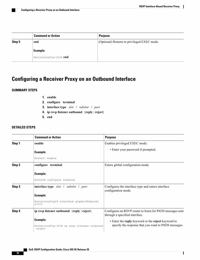
PurposeCommand or Action
(Optional) Returns to privileged EXEC mode.end
Example:
Device(config-if)# end
Step 5
Configuring a Receiver Proxy on an Outbound Interface
SUMMARY STEPS
1. enable2. configure terminal3. interface type slot / subslot / port4. ip rsvp listener outbound {reply | reject}5. end
DETAILED STEPS
PurposeCommand or Action
Enables privileged EXEC mode.enableStep 1
Example:
Router> enable
• Enter your password if prompted.
Enters global configuration mode.configure terminal
Example:
Router# configure terminal
Step 2
Configures the interface type and enters interfaceconfiguration mode.
interface type slot / subslot / port
Example:
Router(config)# interface gigabitEthernet0/0/0
Step 3
Configures an RSVP router to listen for PATHmessages sentthrough a specified interface.
ip rsvp listener outbound {reply | reject}
Example:
Router(config-if)# ip rsvp listener outboundreject
Step 4
• Enter the reply keyword or the reject keyword tospecify the response that you want to PATH messages.
QoS: RSVP Configuration Guide, Cisco IOS XE Release 3S70
RSVP Interface-Based Receiver ProxyConfiguring a Receiver Proxy on an Outbound Interface

PurposeCommand or Action
(Optional) Returns to privileged EXEC mode.end
Example:
Router(config-if)# end
Step 5
Verifying the RSVP Interface-Based Receiver Proxy ConfigurationPerform the following task to verify the configuration. You can use these commands in any order.
You can use the following show commands in user EXEC or privileged EXEC mode.Note
SUMMARY STEPS
1. enable2. show ip rsvp listeners [ip-address| any] [udp | tcp | any | protocol][dst-port | any]3. show ip rsvp sender [detail] [filter [destination address] [dst-port port-number] [source address]
[src-port port-number]]4. show ip rsvp reservation [detail] [filter [destination address] [dst-port port-number] [source address]
[src-port port-number]]5. exit
DETAILED STEPS
PurposeCommand or Action
(Optional) Enables privileged EXEC mode.enableStep 1
Example:
Router> enable
• Enter your password if prompted.
Omit this step if you are using the showcommands in user EXEC mode.
Note
Displays RSVP listeners for a specified port or protocol.show ip rsvp listeners [ip-address| any] [udp | tcp | any |protocol][dst-port | any]
Step 2
Example:
Router# show ip rsvp listeners
QoS: RSVP Configuration Guide, Cisco IOS XE Release 3S 71
RSVP Interface-Based Receiver ProxyVerifying the RSVP Interface-Based Receiver Proxy Configuration
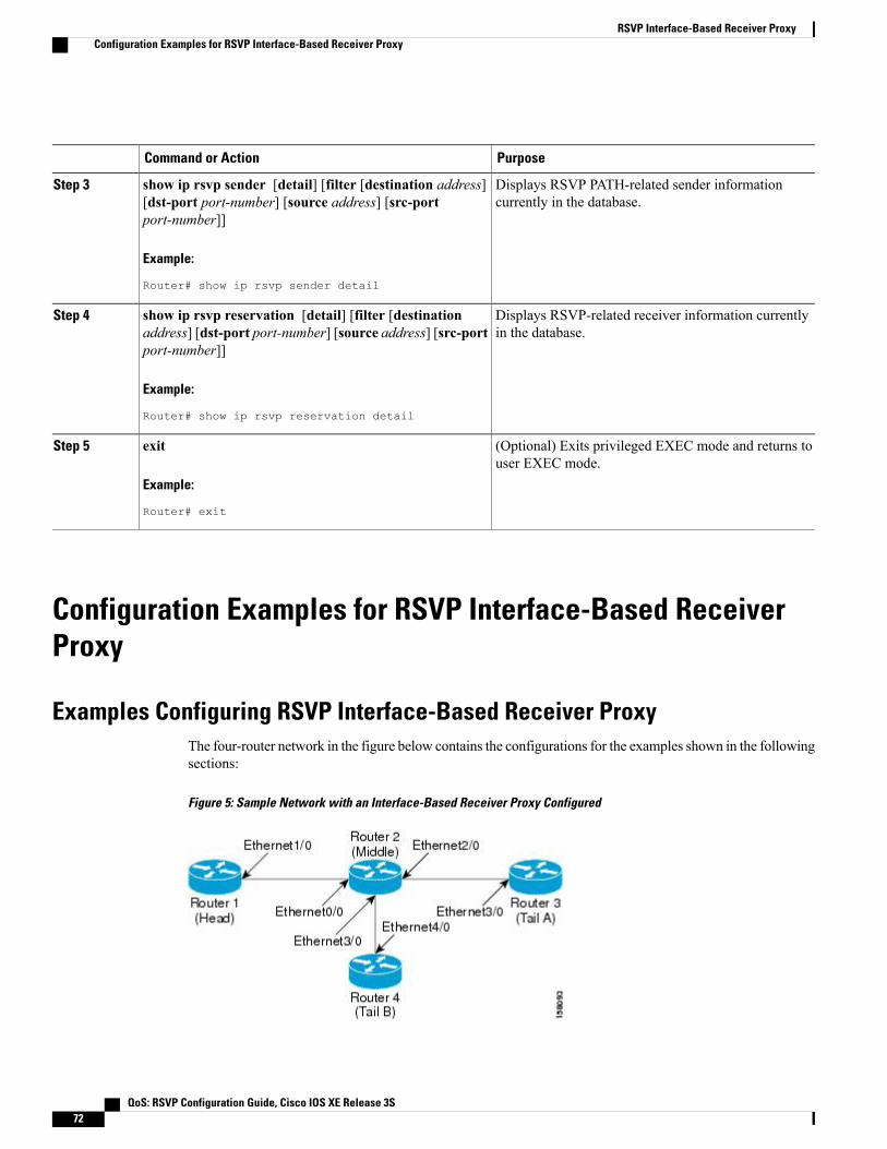
PurposeCommand or Action
Displays RSVP PATH-related sender informationcurrently in the database.
show ip rsvp sender [detail] [filter [destination address][dst-port port-number] [source address] [src-portport-number]]
Step 3
Example:
Router# show ip rsvp sender detail
Displays RSVP-related receiver information currentlyin the database.
show ip rsvp reservation [detail] [filter [destinationaddress] [dst-port port-number] [source address] [src-portport-number]]
Step 4
Example:
Router# show ip rsvp reservation detail
(Optional) Exits privileged EXEC mode and returns touser EXEC mode.
exit
Example:
Router# exit
Step 5
Configuration Examples for RSVP Interface-Based ReceiverProxy
Examples Configuring RSVP Interface-Based Receiver ProxyThe four-router network in the figure below contains the configurations for the examples shown in the followingsections:
Figure 5: Sample Network with an Interface-Based Receiver Proxy Configured
QoS: RSVP Configuration Guide, Cisco IOS XE Release 3S72
RSVP Interface-Based Receiver ProxyConfiguration Examples for RSVP Interface-Based Receiver Proxy

Configuring a Receiver Proxy on a Middle Router on Behalf of Tailend Routers
The following example configures a receiver proxy, also called a listener, on the middle router (Router 2) onbehalf of the two tailend routers (Routers 3 and 4):
Router# configure terminalEnter configuration commands, one per line. End with CNTL/Z.Router(config)# interface gigabitEthernet 2/0/0Router(config-if)# ip rsvp listener outbound replyRouter(config-if)# exitRouter(config)# interface gigabitethernet 3/0/0Router(config-if)# ip rsvp listener outbound rejectRouter(config-if)# end
Configuring PATH Messages from a Headend Router to Tailend Routers to Test the Receiver Proxy
If you do not have another headend router generating RSVP PATH messages available, configure one inthe network for the specific purpose of testing RSVP features such as the receiver proxy. Note that thesecommands are not expected (or supported) in a final deployment.
Note
The following example configures four PATH messages from the headend router (Router 1) to the tailendrouters (Routers 3 and 4):
Router# configure terminalEnter configuration commands, one per line. End with CNTL/Z.Router(config)# ip rsvp sender-host 10.0.0.5 10.0.0.1 TCP 2 2 100 10Router(config)# ip rsvp sender-host 10.0.0.5 10.0.0.1 UDP 1 1 100 10Router(config)# ip rsvp sender-host 10.0.0.7 10.0.0.1 TCP 4 4 100 10Router(config)# ip rsvp sender-host 10.0.0.7 10.0.0.1 UDP 3 3 100 10Router(config)# end
Examples Verifying RSVP Interface-Based Receiver ProxyThis section contains the following verification examples:
Verifying the PATH Messages in the Database
The following example verifies that the PATH messages you configured are in the database:
Router# show ip rsvp senderTo From Pro DPort Sport Prev Hop I/F BPS10.0.0.5 10.0.0.1 TCP 2 2 none none 100K10.0.0.5 10.0.0.1 UDP 1 1 none none 100K10.0.0.7 10.0.0.1 TCP 4 4 none none 100K10.0.0.7 10.0.0.1 UDP 3 3 none none 100K
The following example verifies that a PATH message has been terminated by a receiver proxy configured toreply.
A receiver proxy that is configured to reject does not cause any state to be stored in the RSVP database;therefore, this show command does not display these PATHmessages. Only one PATHmessage is shown.
Note
Router# show ip rsvp sender detailPATH:
QoS: RSVP Configuration Guide, Cisco IOS XE Release 3S 73
RSVP Interface-Based Receiver ProxyExamples Verifying RSVP Interface-Based Receiver Proxy
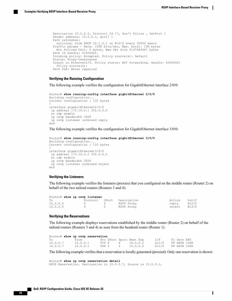
Destination 10.0.0.5, Protocol_Id 17, Don't Police , DstPort 1Sender address: 10.0.0.1, port: 1Path refreshes:arriving: from PHOP 10.1.2.1 on Et0/0 every 30000 msecs
Traffic params - Rate: 100K bits/sec, Max. burst: 10K bytesMin Policed Unit: 0 bytes, Max Pkt Size 2147483647 bytes
Path ID handle: 01000402.Incoming policy: Accepted. Policy source(s): DefaultStatus: Proxy-terminatedOutput on Ethernet2/0. Policy status: NOT Forwarding. Handle: 02000401Policy source(s):
Path FLR: Never repaired
Verifying the Running Configuration
The following example verifies the configuration for GigabitEthernet interface 2/0/0:
Router# show running-config interface gigbitEthernet 2/0/0Building configuration...Current configuration : 132 bytes!interface gigabitEthernet2/0/0ip address 172.16.0.1 255.0.0.0no cdp enableip rsvp bandwidth 2000ip rsvp listener outbound replyend
The following example verifies the configuration for GigabitEthernet interface 3/0/0:
Router# show running-config interface gigbitEthernet 3/0/0Building configuration...Current configuration : 133 bytes!interface gigabitEthernet3/0/0ip address 172.16.0.2 255.0.0.0no cdp enableip rsvp bandwidth 2000ip rsvp listener outbound rejectend
Verifying the Listeners
The following example verifies the listeners (proxies) that you configured on the middle router (Router 2) onbehalf of the two tailend routers (Routers 3 and 4):
Router# show ip rsvp listenerTo Protocol DPort Description Action OutIf10.0.0.0 0 0 RSVP Proxy reply Et2/010.0.0.0 0 0 RSVP Proxy reject Et3/0
Verifying the Reservations
The following example displays reservations established by the middle router (Router 2) on behalf of thetailend routers (Routers 3 and 4) as seen from the headend router (Router 1):
Router# show ip rsvp reservationTo From Pro DPort Sport Next Hop I/F Fi Serv BPS10.0.0.7 10.0.0.1 TCP 4 4 10.0.0.2 Gi1/0 FF RATE 100K10.0.0.7 10.0.0.1 UDP 3 3 10.0.0.2 Gi1/0 FF RATE 100K
The following example verifies that a reservation is locally generated (proxied). Only one reservation is shown:
Router# show ip rsvp reservation detailRSVP Reservation. Destination is 10.0.0.7, Source is 10.0.0.1,
QoS: RSVP Configuration Guide, Cisco IOS XE Release 3S74
RSVP Interface-Based Receiver ProxyExamples Verifying RSVP Interface-Based Receiver Proxy

Protocol is UDP, Destination port is 1, Source port is 1Next Hop: 10.2.3.3 on GigabitEthernet2/0/0Reservation Style is Fixed-Filter, QoS Service is Guaranteed-RateResv ID handle: 01000405.Created: 09:24:24 EST Fri Jun 2 2006Average Bitrate is 100K bits/sec, Maximum Burst is 10K bytesMin Policed Unit: 0 bytes, Max Pkt Size: 0 bytesStatus: ProxiedPolicy: Forwarding. Policy source(s): Default
Verifying CAC on an Outbound Interface
The following example verifies that the proxied reservation performed CAC on the local outbound interface:
Router# show ip rsvp installedRSVP: GigabitEthernet2/0/0 has no installed reservationsRSVP: GigabitEthernet3/0/0BPS To From Protoc DPort Sport100K 10.0.0.7 10.0.0.1 UDP 1 1
Additional ReferencesThe following sections provide references related to the RSVP Interface-Based Receiver Proxy feature.
Related Documents
Document TitleRelated Topic
Cisco IOS Quality of Service Solutions CommandReference
QoS commands: complete command syntax,command modes, command history, defaults, usageguidelines, and examples
"Configuring RSVP" moduleQoS configuration tasks related to RSVP
RSVP Proxy Approaches , Internet draft, October2006 [draft-lefaucheur-tsvwg-rsvp-proxy-00.txt]
Internet draft
Standards
TitleStandard
--No new or modified standards are supported by thisfeature, and support for existing standards has notbeen modified by this feature.
QoS: RSVP Configuration Guide, Cisco IOS XE Release 3S 75
RSVP Interface-Based Receiver ProxyAdditional References

MIBs
MIBs LinkMIB
To locate and downloadMIBs for selected platforms,Cisco software releases, and feature sets, use CiscoMIB Locator found at the following URL:
http://www.cisco.com/go/mibs
No new or modified MIBs are supported by thisfeature, and support for existing MIBs has not beenmodified by this feature.
RFCs
TitleRFC
Resource ReSerVation Protocol (RSVP)RFC 2205
Technical Assistance
LinkDescription
http://www.cisco.com/cisco/web/support/index.htmlThe Cisco Support and Documentation websiteprovides online resources to download documentation,software, and tools. Use these resources to install andconfigure the software and to troubleshoot and resolvetechnical issues with Cisco products and technologies.Access to most tools on the Cisco Support andDocumentation website requires a Cisco.com user IDand password.
Feature Information for RSVP Interface-Based Receiver ProxyThe following table provides release information about the feature or features described in this module. Thistable lists only the software release that introduced support for a given feature in a given software releasetrain. Unless noted otherwise, subsequent releases of that software release train also support that feature.
Use Cisco Feature Navigator to find information about platform support and Cisco software image support.To access Cisco Feature Navigator, go to www.cisco.com/go/cfn. An account on Cisco.com is not required.
QoS: RSVP Configuration Guide, Cisco IOS XE Release 3S76
RSVP Interface-Based Receiver ProxyFeature Information for RSVP Interface-Based Receiver Proxy

Table 4: Feature Information for RSVP Interface-Based Receiver Proxy
Feature InformationReleasesFeature Name
The RSVP Interface-BasedReceiver Proxy feature lets youconfigure a proxy router byoutbound interface instead ofconfiguring a destination addressfor each flow going through thesame interface.
The following commands wereintroduced or modified: ip rsvpbandwidth, ip rsvp listeneroutbound, show ip rsvp listeners,show ip rsvp reservation, showip rsvp sender.
In Cisco IOS XE Release 3.8S,support was added for the CiscoASR 903 Router.
Cisco IOS XE Release 2.6
Cisco IOS XE Release 3.8S
RSVP Interface-Based ReceiverProxy
Glossaryflow --A stream of data traveling between two endpoints across a network (for example, from one LAN stationto another). Multiple flows can be transmitted on a single circuit.
PE router --provider edge router. A router that is part of a service provider’s network and is connected to acustomer edge (CE) router.
proxy --A component of RSVP that manages all locally originated and terminated state.
receiver proxy --A configurable feature that allows a router to proxy RSVP RESV messages for local orremote destinations.
RSVP --Resource Reservation Protocol. A protocol for reserving network resources to provide quality ofservice guarantees to application flows.
set-top box--A computer that acts as a receiver and decodes the incoming signal from a satellite dish, a cablenetwork, or a telephone line.
QoS: RSVP Configuration Guide, Cisco IOS XE Release 3S 77
RSVP Interface-Based Receiver ProxyGlossary

QoS: RSVP Configuration Guide, Cisco IOS XE Release 3S78
RSVP Interface-Based Receiver ProxyGlossary
C H A P T E R 5RSVP Scalability Enhancements
This document describes the Cisco Resource Reservation Protocol (RSVP) scalability enhancements. Itprovides an overview of the feature, includes configuration tasks and examples, and lists related Cisco IOScommand-line interface (CLI) commands.
• Finding Feature Information, page 79
• Prerequisites for RSVP Scalability Enhancements, page 79
• Restrictions for RSVP Scalability Enhancements, page 80
• Information About RSVP Scalability Enhancements, page 80
• How to Configure RSVP Scalability Enhancements, page 81
• Monitoring and Maintaining RSVP Scalability Enhancements, page 88
• Configuration Examples for RSVP Scalability Enhancements, page 89
• Additional References, page 91
• Feature Information for RSVP Scalability Enhancements, page 92
• Glossary, page 93
Finding Feature InformationYour software release may not support all the features documented in this module. For the latest caveats andfeature information, see Bug Search Tool and the release notes for your platform and software release. Tofind information about the features documented in this module, and to see a list of the releases in which eachfeature is supported, see the feature information table at the end of this module.
Use Cisco Feature Navigator to find information about platform support and Cisco software image support.To access Cisco Feature Navigator, go to www.cisco.com/go/cfn. An account on Cisco.com is not required.
Prerequisites for RSVP Scalability EnhancementsThe network must support the following Cisco IOS XE features before the RSVP scalability enhancementsare enabled:
QoS: RSVP Configuration Guide, Cisco IOS XE Release 3S 79

• Resource Reservation Protocol (RSVP)
• Class-based weighted fair queueing (CBWFQ)
Restrictions for RSVP Scalability Enhancements• Sources should not send marked packets without an installed reservation.
• Sources should not send marked packets that exceed the reserved bandwidth.
• Sources should not send marked packets to a destination other than the reserved path.
Information About RSVP Scalability EnhancementsRSVP typically performs admission control, classification, policing, and scheduling of data packets on aper-flow basis and keeps a database of information for each flow. RSVP scalability enhancements let youselect a resource provider (formerly called a quality of service (QoS) provider) and disable data packetclassification so that RSVP performs admission control only. This facilitates integration with service provider(differentiated services (DiffServ)) networks and enables scalability across enterprise networks.
CBWFQ provides the classification, policing, and scheduling functions. CBWFQ puts packets into classesbased on the differentiated services code point (DSCP) value in the packet’s Internet Protocol (IP) header,thereby eliminating the need for per-flow state and per-flow processing.
The figure below shows two enterprise networks interconnected through a service provider (SP) network.The SP network has an IP backbone configured as a DiffServ network. Each enterprise network has a voicegateway connected to an SP edge/aggregation router via a wide area network (WAN) link. The enterprisenetworks are connected to a private branch exchange (PBX).
Figure 6: RSVP/DiffServ Integration Topology
QoS: RSVP Configuration Guide, Cisco IOS XE Release 3S80
RSVP Scalability EnhancementsRestrictions for RSVP Scalability Enhancements

The voice gateways are running classic RSVP, which means RSVP is keeping a state per flow and alsoclassifying, marking, and scheduling packets on a per flow basis. The edge/aggregation routers are runningclassic RSVP on the interfaces (labeled C and D) connected to the voice gateways and running RSVP foradmission control only on the interfaces connected to core routers 1 and 3. The core routers in the DiffServnetwork are not running RSVP, but are forwarding the RSVP messages to the next hop. The core routersinside the DiffServ network implement a specific per hop behavior (PHB) for a collection of flows that havethe same DSCP value.
The voice gateways identify voice data packets and set the appropriate DSCP in their IP headers such that thepackets are classified into the priority class in the edge/aggregation routers and in core routers 1, 2, 3 or 1, 4,3.
The interfaces or the edge/aggregation routers (labeled A and B) connected to core routers 1 and 3 are runningRSVP, but are doing admission control only per flow against the RSVP bandwidth pool configured on theDiffServ interfaces of the edge/aggregation routers. CBWFQ is performing the classification, policing, andscheduling functions.
Benefits of RSVP Scalability Enhancements
Enhanced Scalability
RSVP scalability enhancements handle similar flows on a per-class basis instead of a per-flow basis. Sincefewer resources are required to maintain per-class QoS guarantees, the RSVP scability enhancements providefaster processing results, thereby enhancing scalability.
Improved Router Performance
RSVP scalability enhancements improve router performance by reducing the cost for data-packet classificationand scheduling, which decrease CPU resource consumption. The saved resources can then be used for othernetwork management functions.
How to Configure RSVP Scalability Enhancements
Configuring the Resource Provider
The resource provider was formerly called the QoS provider.Note
QoS: RSVP Configuration Guide, Cisco IOS XE Release 3S 81
RSVP Scalability EnhancementsBenefits of RSVP Scalability Enhancements

SUMMARY STEPS
1. enable2. configure terminal3. interface type slot / subslot / port4. ip rsvp bandwidth [interface-kbps [single-flow-kbps[bc1 kbps | sub-pool kbps]]| percent
percent-bandwidth [single-flow-kbps]]5. ip rsvp resource-provider none6. end
DETAILED STEPS
PurposeCommand or Action
Enables privileged EXEC mode.enableStep 1
Example:
Router> enable
• Enter your password if prompted.
Enters global configuration mode.configure terminal
Example:
Router# configure terminal
Step 2
Configures the interface type and enters interface configuration mode.interface type slot / subslot / port
Example:
Router(config)# interface gigabitEthernet0/0/0
Step 3
Enables RSVP on an interface.ip rsvp bandwidth [interface-kbps[single-flow-kbps[bc1 kbps | sub-pool kbps]]|percent percent-bandwidth [single-flow-kbps]]
Step 4
• The optional interface-kbps and single-flow-kbps argumentsspecify the amount of bandwidth that can be allocated by RSVP
Example:
Router(config-if)# ip rsvp bandwidth 75007500
flows or to a single flow, respectively. Range is from 1 to10000000.
• The optional sub-pooland kbpskeyword and argument specifysubpool traffic and the amount of bandwidth that can be allocatedby RSVP flows. Range is from 1 to 10000000.
Repeat this command for each interface on which you wantto enable RSVP.
Note
The bandwidth that you configure on the interfacemust matchthe bandwidth that you configure for the CBWFQ priorityqueue.
Note
Sets the resource provider to none.ip rsvp resource-provider noneStep 5
QoS: RSVP Configuration Guide, Cisco IOS XE Release 3S82
RSVP Scalability EnhancementsConfiguring the Resource Provider
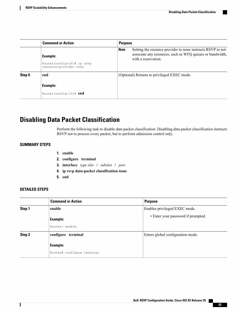
PurposeCommand or Action
Example:
Router(config-if)# ip rsvpresource-provider none
Setting the resource provider to none instructs RSVP to notassociate any resources, such as WFQ queues or bandwidth,with a reservation.
Note
(Optional) Returns to privileged EXEC mode.end
Example:
Router(config-if)# end
Step 6
Disabling Data Packet ClassificationPerform the following task to disable data packet classification. Disabling data packet classification instructsRSVP not to process every packet, but to perform admission control only.
SUMMARY STEPS
1. enable2. configure terminal3. interface type slot / subslot / port4. ip rsvp data-packet classification none5. end
DETAILED STEPS
PurposeCommand or Action
Enables privileged EXEC mode.enableStep 1
Example:
Router> enable
• Enter your password if prompted.
Enters global configuration mode.configure terminal
Example:
Router# configure terminal
Step 2
QoS: RSVP Configuration Guide, Cisco IOS XE Release 3S 83
RSVP Scalability EnhancementsDisabling Data Packet Classification

PurposeCommand or Action
Configures the interface type and enters interfaceconfiguration mode.
interface type slot / subslot / port
Example:
Router(config)# interface gigabitEthernet0/0/0
Step 3
Disables data packet classification.ip rsvp data-packet classification none
Example:
Router(config-if)# ip rsvp data-packetclassification none
Step 4
(Optional) Returns to privileged EXEC mode.end
Example:
Router(config-if)# end
Step 5
Configuring Class Maps and Policy Maps
SUMMARY STEPS
1. enable2. configure terminal3. class-map class-map-name4. exit5. policy-map policy-map-name6. end
DETAILED STEPS
PurposeCommand or Action
Enables privileged EXEC mode.enableStep 1
Example:
Router> enable
• Enter your password if prompted.
QoS: RSVP Configuration Guide, Cisco IOS XE Release 3S84
RSVP Scalability EnhancementsConfiguring Class Maps and Policy Maps

PurposeCommand or Action
Enters global configuration mode.configure terminal
Example:
Router# configure terminal
Step 2
Specifies the name of the class for which you want to create ormodify class-map match criteria and enters the class mapconfiguration mode.
class-map class-map-name
Example:
Router(config)# class-map class1
Step 3
Returns to the global configuration mode.exit
Example:
Router(config-cmap)# exit
Step 4
Specifies the name of the policy map to be created, added to,or modified before you can configure policies for classes whosematch criteria are defined in a class map.
policy-map policy-map-name
Example:
Router(config)# policy-map policy1
Step 5
(Optional) Returns to privileged EXEC mode.end
Example:
Router(config-control-policymap)# end
Step 6
Attaching a Policy Map to an InterfacePerform the following task to attach a policy map to an interface. If at the time you configure the RSVPscalability enhancements, there are existing reservations that use classic RSVP, no additional marking,classification, or scheduling is provided for these flows. You can also delete these reservations after youconfigure the RSVP scalability enhancements.
SUMMARY STEPS
1. enable2. configure terminal3. interface type slot / subslot / port4. service-policy {input | output} policy-map-name5. end
QoS: RSVP Configuration Guide, Cisco IOS XE Release 3S 85
RSVP Scalability EnhancementsAttaching a Policy Map to an Interface

DETAILED STEPS
PurposeCommand or Action
Enables privileged EXEC mode.enableStep 1
Example:
Router> enable
• Enter your password if prompted.
Enters global configuration mode.configure terminal
Example:
Router# configure terminal
Step 2
Configures the interface type and enters interfaceconfiguration mode.
interface type slot / subslot / port
Example:
Router(config)# interface gigabitEthernet 0/0/0
Step 3
Attaches a single policy map to one or more interfaces tospecify the service policy for those interfaces.
service-policy {input | output} policy-map-name
Example:
Router(config-if)# service-policy input policy1
Step 4
(Optional) Returns to privileged EXEC mode.end
Example:
Router(config-if)# end
Step 5
Verifying RSVP Scalability Enhancements Configuration
SUMMARY STEPS
1. Enter the show ip rsvp interface detailcommand to display information about interfaces, subinterfaces,resource providers, and data packet classification. The output in the following example shows that theATM interface 6/0 has resource provider none configured and that data packet classification is turned off:
2. Enter the show ip rsvp installed detailcommand to display information about interfaces, subinterfaces,their admitted reservations, bandwidth, resource providers, and data packet classification.
3. Wait for a while, then enter the show ip rsvp installed detailcommand again. In the following output,notice there is no increment in the number of packets classified:
QoS: RSVP Configuration Guide, Cisco IOS XE Release 3S86
RSVP Scalability EnhancementsVerifying RSVP Scalability Enhancements Configuration

DETAILED STEPS
Step 1 Enter the show ip rsvp interface detailcommand to display information about interfaces, subinterfaces, resource providers,and data packet classification. The output in the following example shows that the ATM interface 6/0 has resourceprovider none configured and that data packet classification is turned off:
Example:
Router# show ip rsvp interface detailAT6/0:Bandwidth:Curr allocated: 190K bits/secMax. allowed (total): 112320K bits/secMax. allowed (per flow): 112320K bits/sec
Neighbors:Using IP encap: 1. Using UDP encaps: 0
DSCP value used in Path/Resv msgs: 0x30RSVP Data Packet Classification is OFFRSVP resource provider is: none
The last two lines in the preceding output verify that the RSVP scalability enhancements (disabled data packetclassification and resource provider none) are present.
Note
Step 2 Enter the show ip rsvp installed detailcommand to display information about interfaces, subinterfaces, their admittedreservations, bandwidth, resource providers, and data packet classification.
Example:
Router# show ip rsvp installed detailRSVP: GigabitEthernet0/0/0 has no installed reservationsRSVP: ATM6/0 has the following installed reservationsRSVP Reservation. Destination is 10.20.20.212, Source is 10.10.10.211,Protocol is UDP, Destination port is 14, Source port is 14Reserved bandwidth: 50K bits/sec, Maximum burst: 1K bytes, Peak rate: 50K bits/secMin Policed Unit: 0 bytes, Max Pkt Size: 1514 bytesResource provider for this flow: NoneConversation supports 1 reservationsData given reserved service: 0 packets (0 bytes)Data given best-effort service: 0 packets (0 bytes)Reserved traffic classified for 54 secondsLong-term average bitrate (bits/sec): 0M reserved, 0M best-effort
RSVP Reservation. Destination is 10.20.20.212, Source is 10.10.10.211,Protocol is UDP, Destination port is 10, Source port is 10Reserved bandwidth: 20K bits/sec, Maximum burst: 1K bytes, Peak rate: 20K bits/secMin Policed Unit: 0 bytes, Max Pkt Size: 1514 bytesResource provider for this flow: NoneConversation supports 1 reservationsData given reserved service: 0 packets (0 bytes)Data given best-effort service: 0 packets (0 bytes)Reserved traffic classified for 80 secondsLong-term average bitrate (bits/sec): 0M reserved, 0M best-effort
Step 3 Wait for a while, then enter the show ip rsvp installed detailcommand again. In the following output, notice there isno increment in the number of packets classified:
Example:
Router# show ip rsvp installed detailRSVP: Ethernet3/3 has no installed reservationsRSVP: ATM6/0 has the following installed reservationsRSVP Reservation. Destination is 10.20.20.212, Source is 10.10.10.211,Protocol is UDP, Destination port is 14, Source port is 14Reserved bandwidth: 50K bits/sec, Maximum burst: 1K bytes, Peak rate: 50K bits/sec
QoS: RSVP Configuration Guide, Cisco IOS XE Release 3S 87
RSVP Scalability EnhancementsVerifying RSVP Scalability Enhancements Configuration

Min Policed Unit: 0 bytes, Max Pkt Size: 1514 bytesResource provider for this flow: NoneConversation supports 1 reservationsData given reserved service: 0 packets (0 bytes)Data given best-effort service: 0 packets (0 bytes)Reserved traffic classified for 60 secondsLong-term average bitrate (bits/sec): 0 reserved, OM best-effort
RSVP Reservation. Destination is 10.20.20.212, Source is 10.10.10.211,Protocol is UDP, Destination port is 10, Source port is 10Reserved bandwidth: 20K bits/sec, Maximum burst: 1K bytes, Peak rate: 20K bits/secMin Policed Unit: 0 bytes, Max Pkt Size: 1514 bytesResource provider for this flow: NoneConversation supports 1 reservationsData given reserved service: 0 packets (0 bytes)Data given best-effort service: 0 packets (0 bytes)Reserved traffic classified for 86 secondsLong-term average bitrate (bits/sec): OM reserved, 0M best-effort
Monitoring and Maintaining RSVP Scalability EnhancementsTo monitor and maintain RSVP scalability enhancements, use the following commands in EXEC mode. Thefollowing commands can be entered in any order.
PurposeCommand
Displays information about interfaces and theiradmitted reservations.Router# show ip rsvp installed
Displays additional information about interfaces andtheir admitted reservations.Router# show ip rsvp installed detail
Displays RSVP-related interface information.Router# show ip rsvp interface
Displays additional RSVP-related interfaceinformation.Router# show ip rsvp interface detail
Displays all or selected configured queueing strategiesand available bandwidth for RSVP reservations.Router# show queueing [custom | fair |
priority | random-detect [interfaceserial-number]]
QoS: RSVP Configuration Guide, Cisco IOS XE Release 3S88
RSVP Scalability EnhancementsMonitoring and Maintaining RSVP Scalability Enhancements
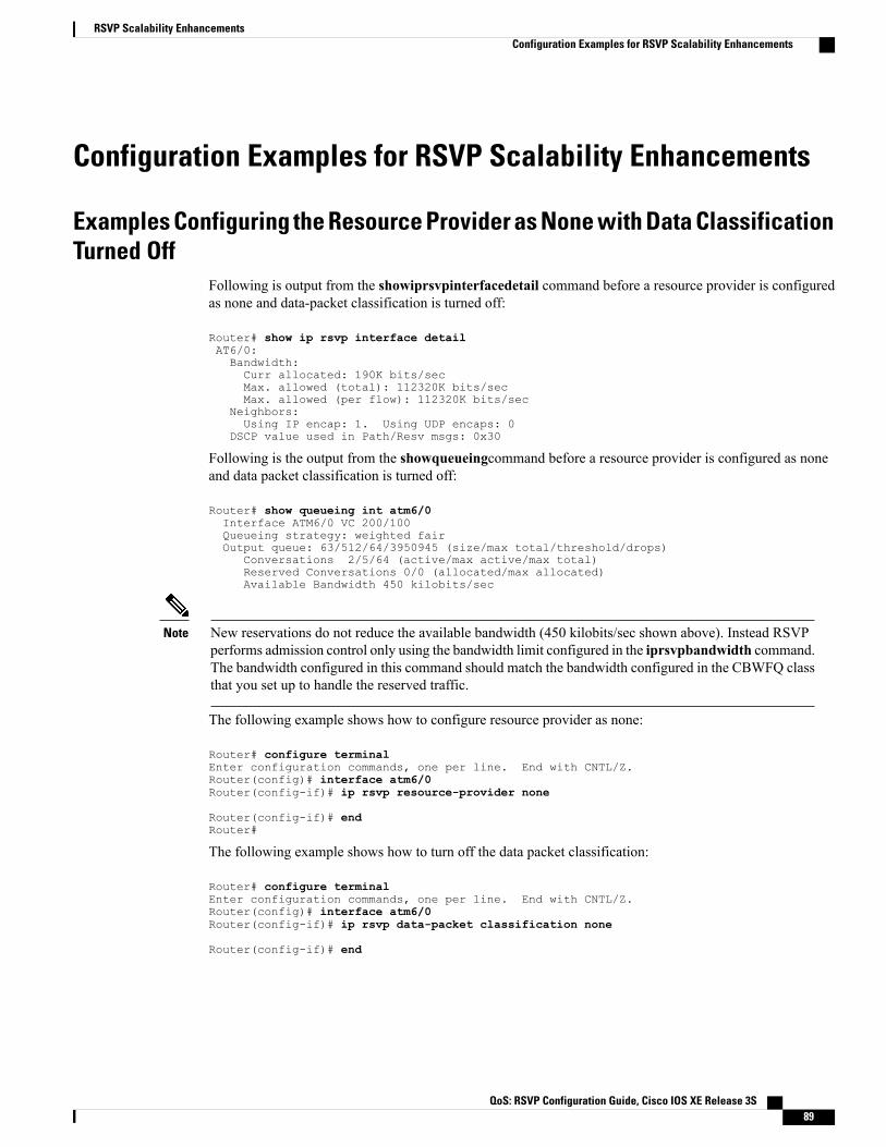
Configuration Examples for RSVP Scalability Enhancements
Examples Configuring the Resource Provider as None with Data ClassificationTurned Off
Following is output from the showiprsvpinterfacedetail command before a resource provider is configuredas none and data-packet classification is turned off:
Router# show ip rsvp interface detailAT6/0:Bandwidth:Curr allocated: 190K bits/secMax. allowed (total): 112320K bits/secMax. allowed (per flow): 112320K bits/sec
Neighbors:Using IP encap: 1. Using UDP encaps: 0
DSCP value used in Path/Resv msgs: 0x30
Following is the output from the showqueueingcommand before a resource provider is configured as noneand data packet classification is turned off:
Router# show queueing int atm6/0Interface ATM6/0 VC 200/100Queueing strategy: weighted fairOutput queue: 63/512/64/3950945 (size/max total/threshold/drops)
Conversations 2/5/64 (active/max active/max total)Reserved Conversations 0/0 (allocated/max allocated)Available Bandwidth 450 kilobits/sec
New reservations do not reduce the available bandwidth (450 kilobits/sec shown above). Instead RSVPperforms admission control only using the bandwidth limit configured in the iprsvpbandwidth command.The bandwidth configured in this command should match the bandwidth configured in the CBWFQ classthat you set up to handle the reserved traffic.
Note
The following example shows how to configure resource provider as none:
Router# configure terminalEnter configuration commands, one per line. End with CNTL/Z.Router(config)# interface atm6/0Router(config-if)# ip rsvp resource-provider none
Router(config-if)# endRouter#
The following example shows how to turn off the data packet classification:
Router# configure terminalEnter configuration commands, one per line. End with CNTL/Z.Router(config)# interface atm6/0Router(config-if)# ip rsvp data-packet classification none
Router(config-if)# end
QoS: RSVP Configuration Guide, Cisco IOS XE Release 3S 89
RSVP Scalability EnhancementsConfiguration Examples for RSVP Scalability Enhancements

Following is the output from the showiprsvpinterfacedetail command after resource provider has beenconfigured as none and data packet classification has been turned off:
Router# show ip rsvp interface detailAT6/0:Bandwidth:Curr allocated: 190K bits/secMax. allowed (total): 112320K bits/secMax. allowed (per flow): 112320K bits/sec
Neighbors:Using IP encap: 1. Using UDP encaps: 0
DSCP value used in Path/Resv msgs: 0x30RSVP Data Packet Classification is OFFRSVP resource provider is: none
The following output from the showiprsvpinstalleddetail command verifies that resource provider none isconfigured and data packet classification is turned off:
Router# show ip rsvp installed detailRSVP: ATM6/0 has the following installed reservationsRSVP Reservation. Destination is 10.20.20.212, Source is 10.10.10.211,Protocol is UDP, Destination port is 14, Source port is 14Reserved bandwidth: 50K bits/sec, Maximum burst: 1K bytes, Peak rate: 50K bits/secMin Policed Unit: 0 bytes, Max Pkt Size: 1514 bytesResource provider for this flow: NoneConversation supports 1 reservationsData given reserved service: 3192 packets (1557696 bytes)Data given best-effort service: 42 packets (20496 bytes)Reserved traffic classified for 271 secondsLong-term average bitrate (bits/sec): 45880 reserved, 603 best-effort
RSVP Reservation. Destination is 10.20.20.212, Source is 10.10.10.211,Protocol is UDP, Destination port is 10, Source port is 10Reserved bandwidth: 20K bits/sec, Maximum burst: 1K bytes, Peak rate: 20K bits/secMin Policed Unit: 0 bytes, Max Pkt Size: 1514 bytesResource provider for this flow: NoneConversation supports 1 reservationsData given reserved service: 1348 packets (657824 bytes)Data given best-effort service: 0 packets (0 bytes)Reserved traffic classified for 296 secondsLong-term average bitrate (bits/sec): 17755 reserved, 0M best-effort
The following output shows no increments in packet counts after the source sends data packets that matchthe reservation:
Router# show ip rsvp installed detailRSVP: GigabitEthernet3/3 has no installed reservationsRSVP: ATM6/0 has the following installed reservationsRSVP Reservation. Destination is 10.20.20.212, Source is 10.10.10.211,Protocol is UDP, Destination port is 14, Source port is 14Reserved bandwidth: 50K bits/sec, Maximum burst: 1K bytes, Peak rate: 50K bits/secMin Policed Unit: 0 bytes, Max Pkt Size: 1514 bytesResource provider for this flow: NoneConversation supports 1 reservationsData given reserved service: 3192 packets (1557696 bytes)Data given best-effort service: 42 packets (20496 bytes)Reserved traffic classified for 282 secondsLong-term average bitrate (bits/sec): 44051 reserved, 579 best-effort
RSVP Reservation. Destination is 145.20.20.212, Source is 145.10.10.211,Protocol is UDP, Destination port is 10, Source port is 10Reserved bandwidth: 20K bits/sec, Maximum burst: 1K bytes, Peak rate: 20K bits/secMin Policed Unit: 0 bytes, Max Pkt Size: 1514 bytesResource provider for this flow: NoneConversation supports 1 reservationsData given reserved service: 1348 packets (657824 bytes)Data given best-effort service: 0 packets (0 bytes)Reserved traffic classified for 307 secondsLong-term average bitrate (bits/sec): 17121 reserved, 0M best-effort
QoS: RSVP Configuration Guide, Cisco IOS XE Release 3S90
RSVP Scalability EnhancementsExamples Configuring the Resource Provider as None with Data Classification Turned Off

The following output verifies that data packet classification is occurring:
Router# show ip rsvp installed detailEnter configuration commands, one per line. End with CNTL/Z.RSVP: ATM6/0 has the following installed reservationsRSVP Reservation. Destination is 10.20.20.212, Source is 10.10.10.211,Protocol is UDP, Destination port is 14, Source port is 14Reserved bandwidth: 50K bits/sec, Maximum burst: 1K bytes, Peak rate: 50K bits/secMin Policed Unit: 0 bytes, Max Pkt Size: 1514 bytesResource provider for this flow: NoneConversation supports 1 reservationsData given reserved service: 3683 packets (1797304 bytes)Data given best-effort service: 47 packets (22936 bytes)Reserved traffic classified for 340 secondsLong-term average bitrate (bits/sec): 42201 reserved, 538 best-effort
RSVP Reservation. Destination is 10.20.20.212, Source is 10.10.10.211,Protocol is UDP, Destination port is 10, Source port is 10Reserved bandwidth: 20K bits/sec, Maximum burst: 1K bytes, Peak rate: 20K bits/secMin Policed Unit: 0 bytes, Max Pkt Size: 1514 bytesResource provider for this flow: NoneConversation supports 1 reservationsData given reserved service: 1556 packets (759328 bytes)Data given best-effort service: 0 packets (0 bytes)Reserved traffic classified for 364 secondsLong-term average bitrate (bits/sec): 16643 reserved, 0M best-effort
You can use debugiprsvptraffic-control and debugiprsvpwfq simultaneously. Use theshowdebugcommand to see which debugging commands are enabled.
Note
Additional ReferencesThe following sections provide references related to the RSVP Scalability Enhancements feature.
Related Documents
Document TitleRelated Topic
Cisco IOS Master Commands List, All ReleasesCisco IOS commands
Cisco IOS Quality of Service Solutions CommandReference
QoS commands: complete command syntax,command modes, command history, defaults, usageguidelines, and examples
"Configuring RSVP" moduleQoS configuration tasks related to RSVP
Standards
TitleStandard
--No new or modified standards are supported by thisfeature, and support for existing standards has notbeen modified by this feature.
QoS: RSVP Configuration Guide, Cisco IOS XE Release 3S 91
RSVP Scalability EnhancementsAdditional References

MIBs
MIBs LinkMIB
To locate and downloadMIBs for selected platforms,software releases, and feature sets, use Cisco MIBLocator found at the following URL:
http://www.cisco.com/go/mibs
None
RFCs
TitleRFC
Resource Reservation ProtocolRFC 2205
RSVP Management Information Base using SMIv2RFC 2206
Technical Assistance
LinkDescription
http://www.cisco.com/cisco/web/support/index.htmlThe Cisco Support and Documentation websiteprovides online resources to download documentation,software, and tools. Use these resources to install andconfigure the software and to troubleshoot and resolvetechnical issues with Cisco products and technologies.Access to most tools on the Cisco Support andDocumentation website requires a Cisco.com user IDand password.
Feature Information for RSVP Scalability EnhancementsThe following table provides release information about the feature or features described in this module. Thistable lists only the software release that introduced support for a given feature in a given software releasetrain. Unless noted otherwise, subsequent releases of that software release train also support that feature.
Use Cisco Feature Navigator to find information about platform support and Cisco software image support.To access Cisco Feature Navigator, go to www.cisco.com/go/cfn. An account on Cisco.com is not required.
QoS: RSVP Configuration Guide, Cisco IOS XE Release 3S92
RSVP Scalability EnhancementsFeature Information for RSVP Scalability Enhancements

Table 5: Feature Information for RSVP Scalability Enhancements
Feature InformationReleasesFeature Name
RSVP scalability enhancements letyou select a resource provider(formerly called a QoS provider)and disable data packetclassification so that RSVPperforms admission control only.This facilitates integration withservice provider (DiffServ)networks and enables scalabilityacross enterprise networks.
The following commands wereintroduced or modified: debug iprsvp traffic-control, debug iprsvp wfq, ip rsvp data-packetclassification none, ip rsvpresource-provider, show ip rsvpinstalled, show ip rsvp interface,show queueing.
In Cisco IOS XE Release 3.8S,support was added for the CiscoASR 903 Router.
Cisco IOS XE Release 2.6
Cisco IOS XE Release 3.8S
RSVP Scalability Enhancements
Glossaryadmission control --The process by which an RSVP reservation is accepted or rejected based on end-to-endavailable network resources.
aggregate --A collection of packets with the same DSCP.
bandwidth --The difference between the highest and lowest frequencies available for network signals. Thisterm also describes the rated throughput capacity of a given network medium or protocol.
CBWFQ -- class-based weighted fair queueing. A queueing mechanism that extends the standard WFQfunctionality to provide support for user-defined traffic classes.
DiffServ --differentiated services. An architecture based on a simple model where traffic entering a networkis classified and possibly conditioned at the boundaries of the network. The class of traffic is then identifiedwith a DS code point or bit marking in the IP header. Within the core of the network, packets are forwardedaccording to the per-hop behavior associated with the DS code point.
DSCP --differentiated services code point. The six most significant bits of the 1-byte IP type of service (ToS)field. The per-hop behavior represented by a particular DSCP value is configurable. DSCP values rangebetween 0 and 63.
enterprise network --A large and diverse network connecting most major points in a company or otherorganization.
QoS: RSVP Configuration Guide, Cisco IOS XE Release 3S 93
RSVP Scalability EnhancementsGlossary

flow --A stream of data traveling between two endpoints across a network (for example, from one LAN stationto another). Multiple flows can be transmitted on a single circuit.
packet --A logical grouping of information that includes a header containing control information and (usually)user data. Packets most often refer to network-layer units of data.
PBX --private branch exchange. A digital or analog telephone switchboard located on the subscriber premisesand used to connect private and public telephone networks.
PHB --per-hop behavior. A DiffServ concept that specifies how specifically marked packets are to be treatedby each DiffServ router.
QoS --quality of service. A measure of performance for a transmission system that reflects its transmissionquality and service availability.
RSVP --Resource Reservation Protocol. A protocol for reserving network resources to provide quality ofservice guarantees to application flows.
Voice over IP --See VoIP.
VoIP --Voice over IP. The ability to carry normal telephony-style voice over an IP-based internet maintainingtelephone-like functionality, reliability, and voice quality.
WFQ --weighted fair queueing. A queue management algorithm that provides a certain fraction of linkbandwidth to each of several queues, based on the relative bandwidth applied to each of the queues.
QoS: RSVP Configuration Guide, Cisco IOS XE Release 3S94
RSVP Scalability EnhancementsGlossary

C H A P T E R 6Control Plane DSCP Support for RSVP
This document describes the Cisco Control Plane DSCP Support for RSVP feature.
• Finding Feature Information, page 95
• Prerequisites for Control Plane DSCP Support for RSVP, page 95
• Restrictions for Control Plane DSCP Support for RSVP, page 96
• Information About Control Plane DSCP Support for RSVP, page 96
• How to Configure Control Plane DSCP Support for RSVP, page 97
• Configuration Examples for Control Plane DSCP Support for RSVP, page 100
• Additional References, page 100
• Feature Information for Control Plane DSCP Support for RSVP, page 101
• Glossary, page 102
Finding Feature InformationYour software release may not support all the features documented in this module. For the latest caveats andfeature information, see Bug Search Tool and the release notes for your platform and software release. Tofind information about the features documented in this module, and to see a list of the releases in which eachfeature is supported, see the feature information table at the end of this module.
Use Cisco Feature Navigator to find information about platform support and Cisco software image support.To access Cisco Feature Navigator, go to www.cisco.com/go/cfn. An account on Cisco.com is not required.
Prerequisites for Control Plane DSCP Support for RSVPThe network must support Resource Reservation Protocol (RSVP) before the Control Plane DSCP Supportfor RSVP feature is enabled.
QoS: RSVP Configuration Guide, Cisco IOS XE Release 3S 95

Restrictions for Control Plane DSCP Support for RSVPControl plane DSCP support for RSVP can be configured on interfaces and subinterfaces only. It affects allRSVP messages that are sent out on the interface or that are present on any logical circuit of the interface,including subinterfaces, permanent virtual circuits (PVCs), and switched virtual circuits (SVCs).
Information About Control Plane DSCP Support for RSVPTypically, networks operate on a best-effort delivery basis, which means that all traffic has equal priority andan equal chance of being delivered in a timely manner.When congestion occurs, all traffic has an equal chanceof being dropped.
Before traffic can be handled according to its unique requirements, it must be identified or labeled. There arenumerous classification techniques for doing this. These include Layer 3 schemes such as IP precedence ordifferentiated services code point (DSCP), Layer 2 schemes such as 802.1P, and implicit characteristics ofthe data itself, such as the traffic type using the Real-Time Transport Protocol (RTP) and a defined port range.
The Control Plane DSCP Support for RSVP feature allows you to set the priority value in the type of service(ToS) byte or differentiated services (DiffServ) field in the IP header for RSVP messages. The IP headerfunctions with resource providers such as weighted fair queueing (WFQ), so that voice frames have priorityover data fragments and data frames. When packets arrive in a router’s output queue, the voice packets areplaced ahead of the data frames.
The figure below shows a path message originating from a sender with a DSCP value of 0 (the default), whichis changed ito 5 to give the message a higher priority, and it shows a reservation (resv) message originatingfrom a receiver with a DSCP of 3.
Figure 7: Control Plane DSCP Support for RSVP
Raising the DSCP value reduces the possibility of packets being dropped, thereby improving call setup timein VoIP environments.
QoS: RSVP Configuration Guide, Cisco IOS XE Release 3S96
Control Plane DSCP Support for RSVPRestrictions for Control Plane DSCP Support for RSVP

Benefits of Control Plane DSCP Support for RSVP
Faster Call Setup Time
The Control Plane DSCP Support for RSVP feature allows you to set the priority for RSVP messages. In aDiffServ QoS environment, higher-priority packets get serviced before lower-priority packets, therebyimproving the call setup time for RSVP sessions.
Improved Message Delivery
During periods of congestion, routers drop lower-priority traffic before they drop higher-priority traffic. SinceRSVP messages can now be marked with higher priority, the likelihood of these messages being dropped issignificantly reduced.
Faster Recovery After Failure Conditions
When heavy congestion occurs, many packets are dropped. Network resources attempt to retransmit almostinstantaneously, resulting in further congestion. This leads to a considerable reduction in throughput.
Previously, RSVP messages were marked best effort and subject to being dropped by congestion avoidancemechanisms such as weighted random early detection (WRED). However, with the Control Plane DSCPSupport for RSVP feature, RSVP messages are likely to be dropped later, if at all, thereby providing fasterrecovery of RSVP reservations.
How to Configure Control Plane DSCP Support for RSVP
Enabling RSVP on an Interface
SUMMARY STEPS
1. enable2. configure terminal3. interface type slot / subslot / port4. ip rsvp bandwidth [interface-kbps] [single-flow-kbps]
DETAILED STEPS
PurposeCommand or Action
Enables privileged EXEC mode.enableStep 1
Example:
Router> enable
• Enter your password if prompted.
QoS: RSVP Configuration Guide, Cisco IOS XE Release 3S 97
Control Plane DSCP Support for RSVPBenefits of Control Plane DSCP Support for RSVP

PurposeCommand or Action
Enters global configuration mode.configure terminal
Example:
Router# configure terminal
Step 2
Enters interface configuration mode for a specificinterface.
interface type slot / subslot / port
Example:
Router(config)# interface gigbitEthernet 0/0/0
Step 3
Enables RSVP on an interface.ip rsvp bandwidth [interface-kbps] [single-flow-kbps]
Example:
Router(config-if)# ip rsvp bandwidth 23 43
Step 4
Specifying the DSCP
SUMMARY STEPS
1. enable2. configure terminal3. interface type slot / subslot / port4. ip rsvp signalling dscp value
DETAILED STEPS
PurposeCommand or Action
Enables privileged EXEC mode.enableStep 1
Example:
Router> enable
• Enter your password if prompted.
Enters global configuration mode.configure terminal
Example:
Router# configure terminal
Step 2
QoS: RSVP Configuration Guide, Cisco IOS XE Release 3S98
Control Plane DSCP Support for RSVPSpecifying the DSCP
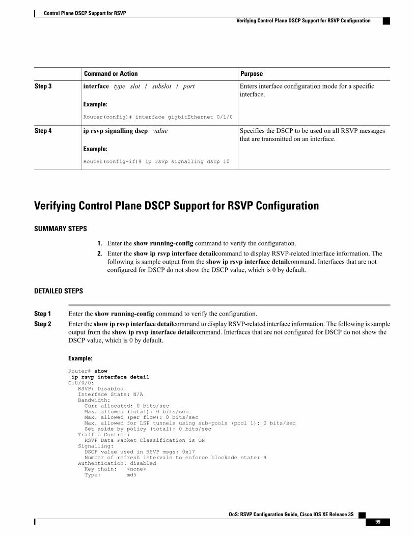
PurposeCommand or Action
Enters interface configuration mode for a specificinterface.
interface type slot / subslot / port
Example:
Router(config)# interface gigbitEthernet 0/1/0
Step 3
Specifies the DSCP to be used on all RSVP messagesthat are transmitted on an interface.
ip rsvp signalling dscp value
Example:
Router(config-if)# ip rsvp signalling dscp 10
Step 4
Verifying Control Plane DSCP Support for RSVP Configuration
SUMMARY STEPS
1. Enter the show running-config command to verify the configuration.2. Enter the show ip rsvp interface detailcommand to display RSVP-related interface information. The
following is sample output from the show ip rsvp interface detailcommand. Interfaces that are notconfigured for DSCP do not show the DSCP value, which is 0 by default.
DETAILED STEPS
Step 1 Enter the show running-config command to verify the configuration.Step 2 Enter the show ip rsvp interface detailcommand to display RSVP-related interface information. The following is sample
output from the show ip rsvp interface detailcommand. Interfaces that are not configured for DSCP do not show theDSCP value, which is 0 by default.
Example:
Router# showip rsvp interface detailGi0/0/0:
RSVP: DisabledInterface State: N/ABandwidth:Curr allocated: 0 bits/secMax. allowed (total): 0 bits/secMax. allowed (per flow): 0 bits/secMax. allowed for LSP tunnels using sub-pools (pool 1): 0 bits/secSet aside by policy (total): 0 bits/sec
Traffic Control:RSVP Data Packet Classification is ON
Signalling:DSCP value used in RSVP msgs: 0x17Number of refresh intervals to enforce blockade state: 4
Authentication: disabledKey chain: <none>Type: md5
QoS: RSVP Configuration Guide, Cisco IOS XE Release 3S 99
Control Plane DSCP Support for RSVPVerifying Control Plane DSCP Support for RSVP Configuration

Window size: 1Challenge: disabled
FRR Extension:Backup Path: Not Configured
BFD Extension:State: DisabledInterval: Not Configured
RSVP Hello Extension:State: Disabled
RFC 3175 Aggregation: DisabledRole: exterior.
Configuration Examples for Control Plane DSCP Support forRSVP
The following example shows how to enable RSVP on an interface, specify the DSCP, and verify the controlplane DSCP support for RSVP.
Router> enableRouter# config terminalRouter(config)# interface gigabitethernet 3/1/0Router(config-if)# ip rsvp bandwidth 7500 7500Router(config-if)# ip rsvp signalling dscp 48Router(config-if)# endThe following example shows how to display the RSVP-related information.
Router# show running-config interface gigabitEthernet 0/0/0interface gigabitEthernet 0/0/0ip address 10.10.10.1 255.255.255.0fair-queue 64 256 235ip rsvp signalling dscp 48ip rsvp bandwidth 7500 7500
Additional ReferencesThe following sections provide references related to the Control Plane DSCP Support for RSVP feature.
Related Documents
Document TitleRelated Topic
Cisco IOS Master Commands List, All ReleasesCisco IOS commands
Cisco IOS Quality of Service Solutions CommandReference
RSVP Commands: complete command syntax,command modes, command history, defaults, usageguidelines, and examples
"Quality of Service Overview" moduleQuality of service overview
QoS: RSVP Configuration Guide, Cisco IOS XE Release 3S100
Control Plane DSCP Support for RSVPConfiguration Examples for Control Plane DSCP Support for RSVP

Standards
TitleStandard
--None
MIBs
MIBs LinkMIB
To locate and downloadMIBs for selected platforms,software releases, and feature sets, use Cisco MIBLocator found at the following URL:
http://www.cisco.com/go/mibs
None
RFCs
TitleRFC
Resource Reservation ProtocolRFC 2205
RSVP Management Information Base using SMIv2RFC 2206
Technical Assistance
LinkDescription
http://www.cisco.com/cisco/web/support/index.htmlThe Cisco Support and Documentation websiteprovides online resources to download documentation,software, and tools. Use these resources to install andconfigure the software and to troubleshoot and resolvetechnical issues with Cisco products and technologies.Access to most tools on the Cisco Support andDocumentation website requires a Cisco.com user IDand password.
Feature Information for Control Plane DSCP Support for RSVPThe following table provides release information about the feature or features described in this module. Thistable lists only the software release that introduced support for a given feature in a given software releasetrain. Unless noted otherwise, subsequent releases of that software release train also support that feature.
Use Cisco Feature Navigator to find information about platform support and Cisco software image support.To access Cisco Feature Navigator, go to www.cisco.com/go/cfn. An account on Cisco.com is not required.
QoS: RSVP Configuration Guide, Cisco IOS XE Release 3S 101
Control Plane DSCP Support for RSVPFeature Information for Control Plane DSCP Support for RSVP

Table 6: Feature Information for Control Plane DSCP Support for RSVP
Feature InformationReleasesFeature Name
The Control Plane DSCP Supportfor RSVP feature allows you to setthe priority value in ToS byte orDiffServ field in the IP header forRSVP messages.
The following commands wereintroduced or modified: ip rsvpsignalling dscp, show ip rsvpinterface.
Cisco IOS XE Release 2.6Control Plane DSCP Support forRSVP
GlossaryCBWFQ -- class-based weighted fair queueing. A queueing mechanism that extends the standard WFQfunctionality to provide support for user-defined traffic classes.
DiffServ --differentiated services. An architecture based on a simple model where traffic that is entering anetwork is classified and possibly conditioned at the boundaries of the network. The class of traffic is thenidentified with a DS code point or bit marking in the IP header. Within the core of the network, packets areforwarded according to the per-hop behavior associated with the DS code point.
DSCP --differentiated services code point. The six most significant bits of the 1-byte IP type of service (ToS)field. The per-hop behavior represented by a particular DSCP value is configurable. DSCP values rangebetween 0 and 63.
IP precedence --The three most significant bits of the 1-byte type of service (ToS) field. IP precedence valuesrange between 0 for low priority and 7 for high priority.
latency --The delay between the timewhen a device receives a packet and the timewhen the packet is forwardedout the destination port.
marking --The process of setting a Layer 3 DSCP value in a packet.
QoS --quality of service. A measure of performance for a transmission system that reflects its transmissionquality and service availability.
RSVP --Resource Reservation Protocol. A protocol for reserving network resources to provide quality ofservice guarantees to application flows.
ToS --type of service. An 8-bit value in the IP header field.
type of service --See ToS.
Voice over IP --See VoIP.
VoIP --Voice over IP. The ability to carry normal telephony-style voice over an IP-based internet whilemaintaining telephone-like functionality, reliability, and voice quality.
WFQ --weighted fair queueing. A queue management algorithm that provides a certain fraction of linkbandwidth to each of several queues, based on relative bandwidth applied to each of the queues.
QoS: RSVP Configuration Guide, Cisco IOS XE Release 3S102
Control Plane DSCP Support for RSVPGlossary
WRED --weighted random early detection. A congestion avoidance mechanism that slows traffic by randomlydropping packets when there is congestion.
QoS: RSVP Configuration Guide, Cisco IOS XE Release 3S 103
Control Plane DSCP Support for RSVPGlossary

QoS: RSVP Configuration Guide, Cisco IOS XE Release 3S104
Control Plane DSCP Support for RSVPGlossary

C H A P T E R 7MPLS TE - Tunnel-Based Admission Control
The MPLS TE--Tunnel-Based Admission Control (TBAC) feature enables classic Resource ReservationProtocol (RSVP) unicast reservations that are traveling across a Multiprotocol Label Switching trafficengineering (MPLS TE) core to be aggregated over an MPLS TE tunnel.
• Finding Feature Information, page 105
• Prerequisites for MPLS TE - Tunnel-Based Admission Control, page 105
• Restrictions for MPLS TE - Tunnel-Based Admission Control, page 106
• Information About MPLS TE - Tunnel-Based Admission Control, page 106
• How to Configure MPLS TE - Tunnel-Based Admission Control, page 108
• Configuration Examples for MPLS TE - Tunnel-Based Admission Control, page 113
• Additional References, page 118
• Feature Information for MPLS TE - Tunnel-Based Admission Control, page 120
• Glossary, page 120
Finding Feature InformationYour software release may not support all the features documented in this module. For the latest caveats andfeature information, see Bug Search Tool and the release notes for your platform and software release. Tofind information about the features documented in this module, and to see a list of the releases in which eachfeature is supported, see the feature information table at the end of this module.
Use Cisco Feature Navigator to find information about platform support and Cisco software image support.To access Cisco Feature Navigator, go to www.cisco.com/go/cfn. An account on Cisco.com is not required.
Prerequisites for MPLS TE - Tunnel-Based Admission Control• You must configure an MPLS TE tunnel in the network.
• You must configure RSVP on one or more interfaces on at least two neighboring routers that share alink within the network.
QoS: RSVP Configuration Guide, Cisco IOS XE Release 3S 105

Restrictions for MPLS TE - Tunnel-Based Admission Control• Only IPv4 unicast RSVP flows are supported.
• Primary, one-hop tunnels are not supported. The TE tunnel cannot be a member of a class-based tunnelselection (CBTS) bundle.
• Multitopology Routing (MTR) is not supported.
• Only preestablished aggregates are supported. They can be configured statically or dynamically usingcommand-line interface (CLI) commands.
Information About MPLS TE - Tunnel-Based Admission Control
Feature Overview of MPLS TE - Tunnel-Based Admission ControlTBAC aggregates reservations from multiple, classic RSVP sessions over different forms of tunnelingtechnologies that includeMPLS TE tunnels, which act as aggregate reservations in the core. The figure belowgives an overview of TBAC.
Figure 8: TBAC Overview
The figure below shows three RSVP end-to-end (E2E) flows that originate at routers on the far left, andterminate on routers at the far right. These flows are classic RSVP unicast flows, meaning that RSVP ismaintaining a state for each flow. There is nothing special about these flows, except that along their path,these flows encounter an MPLS-TE core, where there is a desire to avoid creating a per-flow RSVP state.
When the E2E flows reach the edge of the MPLS-TE core, they are aggregated onto a TE tunnel. This meansthat when transiting through the MPLS-TE core, their state is represented by a single state; the TE tunnel iswithin the aggregation region, and their packets are forwarded (label-switched) by the TE tunnel. For example,
QoS: RSVP Configuration Guide, Cisco IOS XE Release 3S106
MPLS TE - Tunnel-Based Admission ControlRestrictions for MPLS TE - Tunnel-Based Admission Control

if 100 E2E flows traverse the same aggregator and deaggregator, rather than creating 100 RSVP states (PATHand RESV messages) within the aggregation region, a single RSVP-TE state is created, that of the aggregate,which is the TE tunnel, to allocate and maintain the resources used by the 100 E2E flows. In particular, thebandwidth consumed by E2E flows within the core is allocated and maintained in aggregate by the TE tunnel.The bandwidth of each E2E flow is normally admitted into the TE tunnel at the headend, just as any E2Eflow’s bandwidth is admitted onto an outbound link in the absence of aggregation.
Benefits of MPLS TE - Tunnel-Based Admission ControlTo understand the benefits of TBAC, you should be familiar with how Call Admission Control (CAC) worksfor RSVP and Quality of Service (QoS).
Cost Effective
Real-time traffic is very sensitive to loss and delay. CAC avoids QoS degradation for real-time traffic becauseCAC ensures that the accepted load always matches the current network capacity. As a result, you do not haveto overprovision the network to compensate for absolute worst peak traffic or for reduced capacity in case offailure.
Improved Accuracy
CAC uses RSVP signaling, which follows the same path as the real-time flow, and routers make a CACdecision at every hop. This ensures that the CAC decision is very accurate and dynamically adjusts to thecurrent conditions such as a reroute or an additional link. Also, RSVP provides an explicit CAC response(admitted or rejected) to the application, so that the application can react appropriately and fast; for example,sending a busy signal for a voice call, rerouting the voice call on an alternate VoIP route, or displaying amessage for video on demand.
RSVP and MPLS TE Combined
TBAC allows you to combine the benefits of RSVP with those of MPLS TE. Specifically, you can use MPLSTE inside the network to ensure that the transported traffic can take advantage of Fast Reroute protection(50-millisecond restoration), Constraint Based Routing (CBR), and aggregate bandwidth reservation.
Seamless Deployment
TBAC allows you to deploy IPv4 RSVP without any impact on the MPLS part of the network because IPv4RSVP is effectively tunneled inside MPLS TE tunnels that operate unchanged as per regular RSVP TE. Noupgrade or additional protocol is needed in the MPLS core.
Enhanced Scaling Capability
TBAC aggregates multiple IPv4 RSVP reservations ingressing from the same MPLS TE headend router intoa single MPLS TE tunnel and egressing from the same MPLS TE tailend router.
QoS: RSVP Configuration Guide, Cisco IOS XE Release 3S 107
MPLS TE - Tunnel-Based Admission ControlBenefits of MPLS TE - Tunnel-Based Admission Control
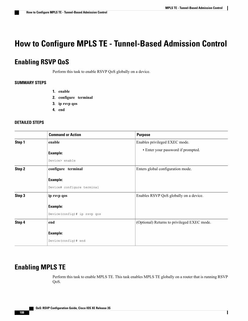
How to Configure MPLS TE - Tunnel-Based Admission Control
Enabling RSVP QoSPerform this task to enable RSVP QoS globally on a device.
SUMMARY STEPS
1. enable2. configure terminal3. ip rsvp qos4. end
DETAILED STEPS
PurposeCommand or Action
Enables privileged EXEC mode.enableStep 1
Example:
Device> enable
• Enter your password if prompted.
Enters global configuration mode.configure terminal
Example:
Device# configure terminal
Step 2
Enables RSVP QoS globally on a device.ip rsvp qos
Example:
Device(config)# ip rsvp qos
Step 3
(Optional) Returns to privileged EXEC mode.end
Example:
Device(config)# end
Step 4
Enabling MPLS TEPerform this task to enable MPLS TE. This task enables MPLS TE globally on a router that is running RSVPQoS.
QoS: RSVP Configuration Guide, Cisco IOS XE Release 3S108
MPLS TE - Tunnel-Based Admission ControlHow to Configure MPLS TE - Tunnel-Based Admission Control

SUMMARY STEPS
1. enable2. configure terminal3. mpls traffic-eng tunnels4. end
DETAILED STEPS
PurposeCommand or Action
Enables privileged EXEC mode.enableStep 1
Example:
Router> enable
• Enter your password if prompted.
Enters global configuration mode.configure terminal
Example:
Router# configure terminal
Step 2
Enables MPLS TE globally on a router.mpls traffic-eng tunnels
Example:
Router(config)# mpls traffic-eng tunnels
Step 3
(Optional) Returns to privileged EXEC mode.end
Example:
Router(config)# end
Step 4
Configuring an MPLS TE Tunnel Interface
Before You Begin
You must configure an MPLS-TE tunnel in your network before you can proceed. For detailed information,see the "MPLS Traffic Engineering (TE)--Automatic Bandwidth Adjustment for TE Tunnels" module.
QoS: RSVP Configuration Guide, Cisco IOS XE Release 3S 109
MPLS TE - Tunnel-Based Admission ControlConfiguring an MPLS TE Tunnel Interface

SUMMARY STEPS
1. enable2. configure terminal3. interface tunnel number4. end
DETAILED STEPS
PurposeCommand or Action
Enables privileged EXEC mode.enableStep 1
Example:
Router> enable
• Enter your password if prompted.
Enters global configuration mode.configure terminal
Example:
Router# configure terminal
Step 2
Specifies a tunnel interface and enters interfaceconfiguration mode.
interface tunnel number
Example:
Router(config)# interface tunnel 1
Step 3
(Optional) Returns to privileged EXEC mode.end
Example:
Router(config-if)# end
Step 4
Configuring RSVP Bandwidth on an MPLS TE Tunnel InterfacePerform this task to configure RSVP bandwidth on the MPLS TE tunnel interface that you are using for theaggregation.
QoS: RSVP Configuration Guide, Cisco IOS XE Release 3S110
MPLS TE - Tunnel-Based Admission ControlConfiguring RSVP Bandwidth on an MPLS TE Tunnel Interface

SUMMARY STEPS
1. enable2. configure terminal3. interface tunnel number4. ip rsvp bandwidth [interface-kbps] [single-flow-kbps]5. end
DETAILED STEPS
PurposeCommand or Action
Enables privileged EXEC mode.enableStep 1
Example:
Router> enable
• Enter your password if prompted.
Enters global configuration mode.configure terminal
Example:
Router# configure terminal
Step 2
Specifies a tunnel interface and enters interface configurationmode.interface tunnel number
Example:
Router(config)# interface tunnel 1
Step 3
Enables RSVP bandwidth on an interface.ip rsvp bandwidth [interface-kbps][single-flow-kbps]
Step 4
• The optional interface-kbps and single-flow-kbps argumentsspecify the amount of bandwidth that can be allocated by
Example:
Router(config-if)# ip rsvp bandwidth 7500
RSVP flows or to a single flow, respectively. Values are from1 to 10000000.
You must enter a value for the interface-kbpsargumenton a tunnel interface.
Note
(Optional) Returns to privileged EXEC mode.end
Example:
Router(config-if)# end
Step 5
QoS: RSVP Configuration Guide, Cisco IOS XE Release 3S 111
MPLS TE - Tunnel-Based Admission ControlConfiguring RSVP Bandwidth on an MPLS TE Tunnel Interface

Verifying the TBAC Configuration
You can use the following show commands in user EXEC or privileged EXEC mode, in any order.Note
SUMMARY STEPS
1. enable2. show ip rsvp3. show ip rsvp reservation [detail] [filter [destination {ip-address | hostname}] [dst-port port-number]
[source {ip-address | hostname}] [src-port port-number]]4. show ip rsvp sender [detail] [filter [destination ip-address | hostname] [dst-port port-number] [source
ip-address | hostname] [src-port port-number]]5. show mpls traffic-eng link-management bandwidth-allocation [summary] [interface-type
interface-number]6. exit
DETAILED STEPS
PurposeCommand or Action
(Optional) Enables privileged EXEC mode.enableStep 1
Example:
Router> enable
• Enter your password if prompted.
Omit this step if you are using the showcommands in user EXEC mode.
Note
Displays specific information for RSVP categories.show ip rsvp
Example:
Router# show ip rsvp
Step 2
Displays RSVP-related receiver information currentlyin the database.
show ip rsvp reservation [detail] [filter [destination{ip-address | hostname}] [dst-port port-number] [source{ip-address | hostname}] [src-port port-number]]
Step 3
Example:
Router# show ip rsvp reservation detail
Displays RSVP PATH-related sender informationcurrently in the database.
show ip rsvp sender [detail] [filter [destination ip-address |hostname] [dst-port port-number] [source ip-address |hostname] [src-port port-number]]
Step 4
QoS: RSVP Configuration Guide, Cisco IOS XE Release 3S112
MPLS TE - Tunnel-Based Admission ControlVerifying the TBAC Configuration
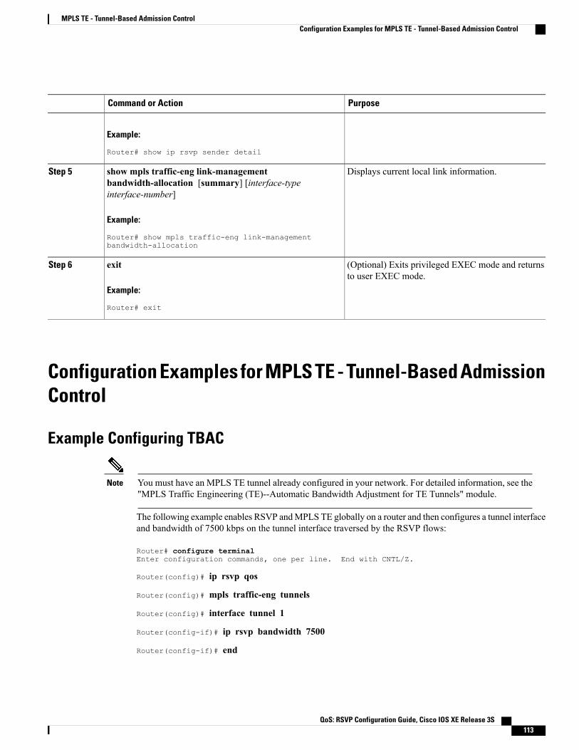
PurposeCommand or Action
Example:
Router# show ip rsvp sender detail
Displays current local link information.show mpls traffic-eng link-managementbandwidth-allocation [summary] [interface-typeinterface-number]
Step 5
Example:
Router# show mpls traffic-eng link-managementbandwidth-allocation
(Optional) Exits privileged EXEC mode and returnsto user EXEC mode.
exit
Example:
Router# exit
Step 6
Configuration Examples for MPLS TE - Tunnel-Based AdmissionControl
Example Configuring TBAC
You must have an MPLS TE tunnel already configured in your network. For detailed information, see the"MPLS Traffic Engineering (TE)--Automatic Bandwidth Adjustment for TE Tunnels" module.
Note
The following example enables RSVP andMPLS TE globally on a router and then configures a tunnel interfaceand bandwidth of 7500 kbps on the tunnel interface traversed by the RSVP flows:
Router# configure terminalEnter configuration commands, one per line. End with CNTL/Z.
Router(config)# ip rsvp qos
Router(config)# mpls traffic-eng tunnels
Router(config)# interface tunnel 1
Router(config-if)# ip rsvp bandwidth 7500
Router(config-if)# end
QoS: RSVP Configuration Guide, Cisco IOS XE Release 3S 113
MPLS TE - Tunnel-Based Admission ControlConfiguration Examples for MPLS TE - Tunnel-Based Admission Control

Example Configuring RSVP Local Policy on a Tunnel InterfaceThe following example configures an RSVP default local policy on a tunnel interface:
Router# configure terminalEnter configuration commands, one per line. End with CNTL/Z.
Router(config)# interface tunnel 1
Router(config-if)# ip rsvp policy local default
Router(config-rsvp-local-if-policy)# max bandwidth single 10
Router(config-rsvp-local-if-policy)# forward all
Router(config-rsvp-local-if-policy)# end
Example Verifying the TBAC ConfigurationThe figure below shows a network in which TBAC is configured.
Figure 9: Sample TBAC Network
The following example verifies that RSVP and MPLS TE are enabled and coexist on the headend router(10.0.0.2 in the figure above):
Router# show ip rsvpRSVP: enabled (on 3 interface(s))RSVP QoS enabled <-------MPLS/TE signalling enabled <------
Signalling:Refresh interval (msec): 30000Refresh misses: 4
.
.
.The following example verifies that RSVP andMPLS TE are enabled and coexist on the tailend router (10.0.0.3in the figure above):
Router# show ip rsvpRSVP: enabled (on 3 interface(s))RSVP QoS enabled <-------MPLS/TE signalling enabled <------
Signalling:Refresh interval (msec): 30000Refresh misses: 4
.
.
.
QoS: RSVP Configuration Guide, Cisco IOS XE Release 3S114
MPLS TE - Tunnel-Based Admission ControlExample Configuring RSVP Local Policy on a Tunnel Interface

The following examples verify that an IPv4 flow is traveling through a TE tunnel (a label-switched path [LSP])on the headend router (10.0.0.2 in the figure above):
Router# show ip rsvp senderTo From Pro DPort Sport Prev Hop I/F BPS10.0.0.3 10.0.0.1 UDP 2 2 10.0.0.1 Et0/0 10K <-- IPv4 flow10.0.0.3 10.0.0.2 0 1 11 none none 100K <-- TE tunnel
Router# show ip rsvp reservationTo From Pro DPort Sport Next Hop I/F Fi Serv BPS10.0.0.3 10.0.0.1 UDP 2 2 10.0.0.3 Tu1 SE RATE 10K <-- IPv4 flow10.0.0.3 10.0.0.2 0 1 11 10.1.0.2 Et1/0 SE LOAD 100K <-- TE tunnel
The following examples verify that an IPv4 flow is traveling through a TE tunnel (LSP) on the tailend router(10.0.0.3 in the figure above):
Router# show ip rsvp senderTo From Pro DPort Sport Prev Hop I/F BPS10.0.0.3 10.0.0.1 UDP 2 2 10.0.0.2 Et1/0 10K <-- IPv4 flow10.0.0.3 10.0.0.2 0 1 11 10.1.0.1 Et1/0 100K <-- TE tunnel
Router# show ip rsvp reservationTo From Pro DPort Sport Next Hop I/F Fi Serv BPS10.0.0.3 10.0.0.1 UDP 2 2 none none SE RATE 10K <-- IPv4 flow10.0.0.3 10.0.0.2 0 1 11 none none SE LOAD 100K <-- TE tunnel
The following examples display detailed information about the IPv4 flow and the TE tunnel (LSP) on theheadend router (10.0.0.2 in the figure above):
Router# show ip rsvp sender detailPATH: <----------------------------------------------- IPv4 flow information begins here.Destination 10.0.0.3, Protocol_Id 17, Don't Police , DstPort 2Sender address: 10.0.0.1, port: 2Path refreshes:arriving: from PHOP 10.0.0.10 on Et0/0 every 30000 msecs. Timeout in 189 sec
Traffic params - Rate: 10K bits/sec, Max. burst: 10K bytesMin Policed Unit: 0 bytes, Max Pkt Size 2147483647 bytes
Path ID handle: 02000412.Incoming policy: Accepted. Policy source(s): DefaultStatus:Output on Tunnel1, out of band. Policy status: Forwarding. Handle: 0800040E <--- TE tunnelverified
Policy source(s): DefaultPath FLR: Never repaired
PATH: <------------------------------------------------ TE tunnel information begins here.Tun Dest: 10.0.0.3 Tun ID: 1 Ext Tun ID: 10.0.0.2Tun Sender: 10.0.0.2 LSP ID: 11Path refreshes:sent: to NHOP 10.1.0.2 on GigabitEthernet1/0/0..
.
Router# show ip rsvp reservation detailRSVP Reservation. Destination is 10.0.0.3, Source is 10.0.0.1,<--- IPv4 flow informationbegins here.Protocol is UDP, Destination port is 2, Source port is 2Next Hop: 10.0.0.3 on Tunnel1, out of band <-------------------- TE tunnel verifiedReservation Style is Shared-Explicit, QoS Service is Guaranteed-Rate...
Reservation: <--------------------------------------- TE Tunnel information begins here.Tun Dest: 10.0.0.3 Tun ID: 1 Ext Tun ID: 10.0.0.2Tun Sender: 10.0.0.2 LSP ID: 11Next Hop: 10.1.0.2 on GigabitEthernet1/0/0Label: 0 (outgoing)
QoS: RSVP Configuration Guide, Cisco IOS XE Release 3S 115
MPLS TE - Tunnel-Based Admission ControlExample Verifying the TBAC Configuration

Reservation Style is Shared-Explicit, QoS Service is Controlled-Load...
Router# show ip rsvp installed detail
RSVP: GigabitEthernet0/0/0 has no installed reservations
RSVP: GigabitEthernet1/0/0 has the following installed reservationsRSVP Reservation. Destination is 10.0.0.3. Source is 10.0.0.2,Protocol is 0 , Destination port is 1, Source port is 11Traffic Control ID handle: 03000405Created: 04:46:55 EST Fri Oct 26 2007 <------ IPv4 flow informationAdmitted flowspec:Reserved bandwidth: 100K bits/sec, Maximum burst: 1K bytes, Peak rate: 100K bits/secMin Policed Unit: 0 bytes, Max Pkt Size: 1500 bytes
Resource provider for this flow: None...
RSVP: Tunnel1 has the following installed reservations <------ TE tunnel verifiedRSVP Reservation. Destination is 10.0.0.3. Source is 10.0.0.1,Protocol is UDP, Destination port is 2, Source port is 2Traffic Control ID handle: 01000415Created: 04:57:07 EST Fri Oct 26 2007 <----- IPv4 flow informationAdmitted flowspec:Reserved bandwidth: 10K bits/sec, Maximum burst: 10K bytes, Peak rate: 10K bits/secMin Policed Unit: 0 bytes, Max Pkt Size: 0 bytes
Resource provider for this flow: None...
Router# show ip rsvp interface detail
Et0/0:RSVP: EnabledInterface State: UpBandwidth:Curr allocated: 0 bits/secMax. allowed (total): 3M bits/secMax. allowed (per flow): 3M bits/sec
.
.
.Et1/0:RSVP: EnabledInterface State: UpBandwidth:Curr allocated: 0 bits/secMax. allowed (total): 3M bits/secMax. allowed (per flow): 3M bits/sec
.
.
.Tu1: <--------------------------------- TE tunnel information begins here.
RSVP: EnabledRSVP aggregation over MPLS TE: EnabledInterface State: UpBandwidth:Curr allocated: 20K bits/secMax. allowed (total): 3M bits/secMax. allowed (per flow): 3M bits/sec
.
.
.
QoS: RSVP Configuration Guide, Cisco IOS XE Release 3S116
MPLS TE - Tunnel-Based Admission ControlExample Verifying the TBAC Configuration
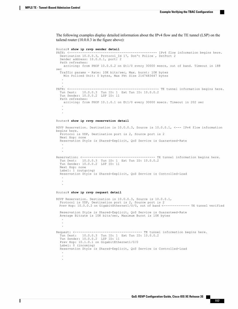
The following examples display detailed information about the IPv4 flow and the TE tunnel (LSP) on thetailend router (10.0.0.3 in the figure above):
Router# show ip rsvp sender detailPATH: <----------------------------------------------- IPv4 flow information begins here.Destination 10.0.0.3, Protocol_Id 17, Don't Police , DstPort 2Sender address: 10.0.0.1, port: 2Path refreshes:arriving: from PHOP 10.0.0.2 on Et1/0 every 30000 msecs, out of band. Timeout in 188
secTraffic params - Rate: 10K bits/sec, Max. burst: 10K bytesMin Policed Unit: 0 bytes, Max Pkt Size 2147483647 bytes...
PATH: <------------------------------------------------ TE tunnel information begins here.Tun Dest: 10.0.0.3 Tun ID: 1 Ext Tun ID: 10.0.0.2Tun Sender: 10.0.0.2 LSP ID: 11Path refreshes:arriving: from PHOP 10.1.0.1 on Et1/0 every 30000 msecs. Timeout in 202 sec...
Router# show ip rsvp reservation detail
RSVP Reservation. Destination is 10.0.0.3, Source is 10.0.0.1, <--- IPv4 flow informationbegins here.Protocol is UDP, Destination port is 2, Source port is 2Next Hop: noneReservation Style is Shared-Explicit, QoS Service is Guaranteed-Rate...
Reservation: <--------------------------------------- TE tunnel information begins here.Tun Dest: 10.0.0.3 Tun ID: 1 Ext Tun ID: 10.0.0.2Tun Sender: 10.0.0.2 LSP ID: 11Next Hop: noneLabel: 1 (outgoing)Reservation Style is Shared-Explicit, QoS Service is Controlled-Load...
Router# show ip rsvp request detail
RSVP Reservation. Destination is 10.0.0.3, Source is 10.0.0.1,Protocol is UDP, Destination port is 2, Source port is 2Prev Hop: 10.0.0.2 on GigabitEthernet1/0/0, out of band <-------------- TE tunnel verified
Reservation Style is Shared-Explicit, QoS Service is Guaranteed-RateAverage Bitrate is 10K bits/sec, Maximum Burst is 10K bytes...
Request: <------------------------------------ TE tunnel information begins here.Tun Dest: 10.0.0.3 Tun ID: 1 Ext Tun ID: 10.0.0.2Tun Sender: 10.0.0.2 LSP ID: 11Prev Hop: 10.1.0.1 on GigabitEthernet1/0/0Label: 0 (incoming)Reservation Style is Shared-Explicit, QoS Service is Controlled-Load...
QoS: RSVP Configuration Guide, Cisco IOS XE Release 3S 117
MPLS TE - Tunnel-Based Admission ControlExample Verifying the TBAC Configuration

Example Verifying the RSVP Local Policy ConfigurationThe following example verifies that a default local policy has been configured on tunnel interface 1:
Device# show run interface tunnnel 1Building configuration...
Current configuration : 419 bytes!interface Tunnel1bandwidth 3000ip unnumbered Loopback0tunnel destination 10.0.0.3tunnel mode mpls traffic-engtunnel mpls traffic-eng autoroute announcetunnel mpls traffic-eng priority 1 1tunnel mpls traffic-eng bandwidth 100tunnel mpls traffic-eng path-option 1 dynamictunnel mpls traffic-eng fast-rerouteip rsvp policy local default <---------------- Local policy information begins here.max bandwidth single 10forward allip rsvp bandwidth 3000end
The following example provides additional information about the default local policyconfigured on tunnel interface 1:Device# show ip rsvp policy local detailTunnel1:Default policy:
Preemption Scope: Unrestricted.Local Override: Disabled.Fast ReRoute: Accept.Handle: BC000413.
Accept ForwardPath: Yes YesResv: Yes YesPathError: Yes YesResvError: Yes Yes
Setup Priority Hold PriorityTE: N/A N/ANon-TE: N/A N/A
Current LimitSenders: 0 N/AReceivers: 1 N/AConversations: 1 N/AGroup bandwidth (bps): 10K N/APer-flow b/w (bps): N/A 10K
Generic policy settings:Default policy: Accept allPreemption: Disabled
Additional ReferencesThe following sections provide references related to the RSVP--VRF Lite Admission Control feature.
QoS: RSVP Configuration Guide, Cisco IOS XE Release 3S118
MPLS TE - Tunnel-Based Admission ControlExample Verifying the RSVP Local Policy Configuration
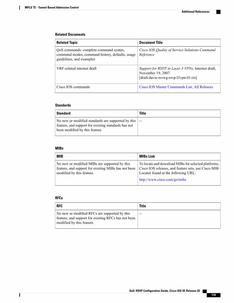
Related Documents
Document TitleRelated Topic
Cisco IOS Quality of Service Solutions CommandReference
QoS commands: complete command syntax,command modes, command history, defaults, usageguidelines, and examples
Support for RSVP in Layer 3 VPNs, Internet draft,November 19, 2007[draft-davie-tsvwg-rsvp-l3vpn-01.txt]
VRF-related internet draft
Cisco IOS Master Commands List, All ReleasesCisco IOS commands
Standards
TitleStandard
--No new or modified standards are supported by thisfeature, and support for existing standards has notbeen modified by this feature.
MIBs
MIBs LinkMIB
To locate and downloadMIBs for selected platforms,Cisco IOS releases, and feature sets, use Cisco MIBLocator found at the following URL:
http://www.cisco.com/go/mibs
No new or modified MIBs are supported by thisfeature, and support for existing MIBs has not beenmodified by this feature.
RFCs
TitleRFC
--No new or modified RFCs are supported by thisfeature, and support for existing RFCs has not beenmodified by this feature.
QoS: RSVP Configuration Guide, Cisco IOS XE Release 3S 119
MPLS TE - Tunnel-Based Admission ControlAdditional References

Technical Assistance
LinkDescription
http://www.cisco.com/cisco/web/support/index.htmlThe Cisco Support and Documentation websiteprovides online resources to download documentation,software, and tools. Use these resources to install andconfigure the software and to troubleshoot and resolvetechnical issues with Cisco products and technologies.Access to most tools on the Cisco Support andDocumentation website requires a Cisco.com user IDand password.
Feature Information for MPLS TE - Tunnel-Based AdmissionControl
The following table provides release information about the feature or features described in this module. Thistable lists only the software release that introduced support for a given feature in a given software releasetrain. Unless noted otherwise, subsequent releases of that software release train also support that feature.
Use Cisco Feature Navigator to find information about platform support and Cisco software image support.To access Cisco Feature Navigator, go to www.cisco.com/go/cfn. An account on Cisco.com is not required.
Table 7: Feature Information for MPLS TE--Tunnel-Based Admission Control (TBAC)
Feature InformationReleasesFeature Name
The MPLS TE--Tunnel-BasedAdmission Control feature enablesclassic Resource ReservationProtocol (RSVP) unicastreservations that are travelingacross an MPLS TE core to beaggregated over an MPLS TEtunnel. The following commandswere introduced or modified: iprsvp qos, show ip rsvp, show iprsvp reservation, show ip rsvpsender, show mpls traffic-englink-managementbandwidth-allocation.
Cisco IOS XE Release 2.6MPLS TE Tunnel-BasedAdmission Control
Glossaryadmission control --The process by which an RSVP reservation is accepted or rejected on the basis ofend-to-end available network resources.
QoS: RSVP Configuration Guide, Cisco IOS XE Release 3S120
MPLS TE - Tunnel-Based Admission ControlFeature Information for MPLS TE - Tunnel-Based Admission Control

QoS --quality of service. A measure of performance for a transmission system that reflects its transmissionquality and service availability. Quality of service focuses on achieving appropriate network performance fornetworked applications; it is superior to best effort performance.
RSVP --Resource Reservation Protocol. A protocol that supports the reservation of resources across an IPnetwork. Applications that run on IP end systems can use RSVP to indicate to other nodes the nature (bandwidth,jitter, maximum burst, and so on) of the packet streams that they want to receive.
VRF --virtual routing and forwarding. An extension of IP routing that provides multiple routing instances. AVRF consists of an IP routing table, a derived forwarding table, a set of interfaces that use the forwardingtable, and a set of rules and routing protocols that determine what goes into the forwarding table. In general,a VRF includes the routing information that defines a customer VPN site that is attached to a provider edge(PE) device.
QoS: RSVP Configuration Guide, Cisco IOS XE Release 3S 121
MPLS TE - Tunnel-Based Admission ControlGlossary

QoS: RSVP Configuration Guide, Cisco IOS XE Release 3S122
MPLS TE - Tunnel-Based Admission ControlGlossary

C H A P T E R 8PfR RSVP Control
The PfR RSVP Control feature introduces the ability to perform application-aware path selection for trafficthat is controlled by Resource Reservation Protocol (RSVP). This feature allows RSVP flows to be learnedby Performance Routing (PfR) and protocol Path messages to be redirected after the PfR master controllerdetermines the best exit using PfR policies.
• Finding Feature Information, page 123
• Information About PfR RSVP Control, page 123
• How to Configure PfR RSVP Control, page 126
• Configuration Examples for PfR RSVP Control, page 138
• Additional References, page 139
• Feature Information for PfR RSVP Control, page 140
Finding Feature InformationYour software release may not support all the features documented in this module. For the latest caveats andfeature information, see Bug Search Tool and the release notes for your platform and software release. Tofind information about the features documented in this module, and to see a list of the releases in which eachfeature is supported, see the feature information table at the end of this module.
Use Cisco Feature Navigator to find information about platform support and Cisco software image support.To access Cisco Feature Navigator, go to www.cisco.com/go/cfn. An account on Cisco.com is not required.
Information About PfR RSVP Control
PfR and RSVP ControlThe PfR RSVP Control feature introduces the ability for Performance Routing (PfR) to learn, monitor, andoptimize Resource Reservation Protocol (RSVP) flows. PfR is an integrated Cisco IOS solution that allowsyou to monitor IP traffic flows and then define policies and rules based on traffic class performance, link load
QoS: RSVP Configuration Guide, Cisco IOS XE Release 3S 123
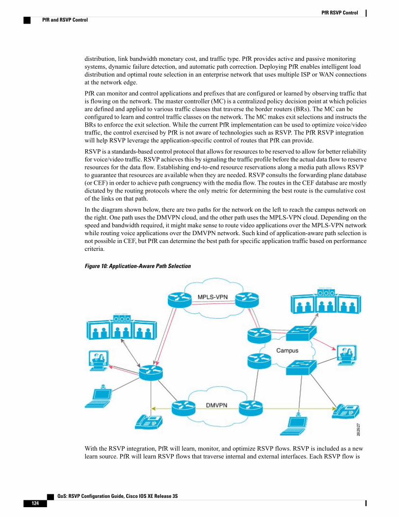
distribution, link bandwidth monetary cost, and traffic type. PfR provides active and passive monitoringsystems, dynamic failure detection, and automatic path correction. Deploying PfR enables intelligent loaddistribution and optimal route selection in an enterprise network that uses multiple ISP or WAN connectionsat the network edge.
PfR can monitor and control applications and prefixes that are configured or learned by observing traffic thatis flowing on the network. The master controller (MC) is a centralized policy decision point at which policiesare defined and applied to various traffic classes that traverse the border routers (BRs). The MC can beconfigured to learn and control traffic classes on the network. The MC makes exit selections and instructs theBRs to enforce the exit selection. While the current PfR implementation can be used to optimize voice/videotraffic, the control exercised by PfR is not aware of technologies such as RSVP. The PfR RSVP integrationwill help RSVP leverage the application-specific control of routes that PfR can provide.
RSVP is a standards-based control protocol that allows for resources to be reserved to allow for better reliabilityfor voice/video traffic. RSVP achieves this by signaling the traffic profile before the actual data flow to reserveresources for the data flow. Establishing end-to-end resource reservations along a media path allows RSVPto guarantee that resources are available when they are needed. RSVP consults the forwarding plane database(or CEF) in order to achieve path congruency with the media flow. The routes in the CEF database are mostlydictated by the routing protocols where the only metric for determining the best route is the cumulative costof the links on that path.
In the diagram shown below, there are two paths for the network on the left to reach the campus network onthe right. One path uses the DMVPN cloud, and the other path uses the MPLS-VPN cloud. Depending on thespeed and bandwidth required, it might make sense to route video applications over the MPLS-VPN networkwhile routing voice applications over the DMVPN network. Such kind of application-aware path selection isnot possible in CEF, but PfR can determine the best path for specific application traffic based on performancecriteria.
Figure 10: Application-Aware Path Selection
With the RSVP integration, PfR will learn, monitor, and optimize RSVP flows. RSVP is included as a newlearn source. PfR will learn RSVP flows that traverse internal and external interfaces. Each RSVP flow is
QoS: RSVP Configuration Guide, Cisco IOS XE Release 3S124
PfR RSVP ControlPfR and RSVP Control

learned as a PfR traffic class and is controlled independently of the other RSVP flows. While filtering of thelearned flows is supported with prefix lists and route maps, aggregating RSVP flows is not advised. The PfRmaster controller (MC) chooses a best exit based on the configured PfR policies and installs route maps toredirect traffic. If any of the RSVP flows enters an Out-of-Policy (OOP) condition, PfR will find and switchthe RSVP flow to a new exit. RSVPwill reinstall the reservation on the new path at the time of refresh (usuallywithin a span of 30 seconds) or as a Fast Local Repair (FLR) case in less than 5 seconds.
The intent of the PfR RSVP Control feature is to identify and install route maps at the time the router receivesan RSVP Path message. The route map captures the data traffic, while RSVP uses this path for the Pathmessage.
RSVP flows are learned as PfR traffic classes defined as a single application flow that can be identified bythe source address, source port, destination address, destination port and IP protocol. This microflow isoptimized as an application by PfR, and a dynamic policy route is created by PfR to forward this traffic classover the selected exit.
All RSVP flows are optimized only after PfR checks that there is enough bandwidth on the exit that is beingconsidered. This information is pushed periodically from the BRs to the MC. On the BR itself, RSVP notifiesPfR every time the bandwidth pool on an interface changes.
Equivalent-Path Round-Robin ResolverPfR introduced a new resolver with the PfR RSVP Control feature. PfR, by default, uses a random resolverto decide between equivalent paths, exits with the same cost determined by the PfR policies. When theround-robin resolver is configured using the equivalent-path-round-robin command, the next exit (next-hopinterface) is selected and compared to the running PfR policy. The round-robin resolver is handed an arrayof equivalent exits from which it chooses in a round-robin fashion. Exits are pruned in the same fashion theyare today by each resolver. If the exit matches the policy, the exit becomes the best exit. The round-robinresolver does not do any specific RSVP checking. To return to using the random resolver, enter the no formof the equivalent-path-round-robin command.
Any PfR traffiic class can use the round-robin resolver, and it provides a load-balancing scheme for multipleequivalent paths as determined by PfR policy.
RSVP Post Dial Delay Timer for Best Path SelectionIn the PfR RSVP Control feature, the rsvp post-dial-delay command was introduced to set a value for theRSVP post dial delay timer that runs on the border routers when RSVP flow learning is enabled on a PfRmaster controller. The timer is updated on the border routers at the start of every PfR learn cycle, and thetimer determines the delay, in milliseconds, before the routing path is returned to RSVP. When the PfR andRSVP integration is enabled, PfR tries to locate a best path for any RSVP flows that are learned before thedelay timer expires. If the current path is not the best path, PfR attempts to install the new path. RSVP reactsto this policy route injection as a case of Fast Local Repair (FLR) and resignals a new reservation path.
RSVP Signaling Retries for Alternative Reservation PathThe PfR RSVP Control feature introduced a new command, rsvp signaling-retries, which is configured onamaster controller and is used to instruct PfR to provide an alternate reservation path when an RSVP reservationreturns an error condition. If an alternate path is provided by PfR, RSVP can resend the reservation signal.
QoS: RSVP Configuration Guide, Cisco IOS XE Release 3S 125
PfR RSVP ControlEquivalent-Path Round-Robin Resolver
The default number of retries is set to 0; no signaling retries are to be permitted, and a reservation error messageis sent when a reservation failure occurs.
Performance Statistics from PfR CommandsThe PfR master controller learns and monitors IP traffic that flows through the border routers, and the mastercontroller selects the best exit for a traffic flow based on configured policies and the performance informationreceived from the border routers. To view some of the performance data collected by the master controller,you can use the following commands:
• show pfr master active-probes
• show pfr master border
• show pfr master exits
• show pfr master statistics
• show pfr master traffic-class
• show pfr master traffic-class performance
All these commands are entered at the master controller, and some of the commands have keywords andarguments to filter the output. For detailed information about these commands, see the Cisco IOS PerformanceRouting Command Reference.
How to Configure PfR RSVP Control
Configuring PfR RSVP Control Using a Learn ListPerform this task on the master controller to define a learn list that contains traffic classes that are automaticallylearned based on RSVP flows and filtered by a prefix list. In this task, the goal is to optimize all video trafficthat is learned from RSVP flows.
The VIDEO traffic class is defined as any prefix that matches 10.100.0.0/16 or 10.200.0.0/16 and a PfR policy,named POLICY_RSVP_VIDEO, is created.
The learn lists are referenced in a PfR policy using a PfR map and are activated using the policy-rules (PfR)command.
QoS: RSVP Configuration Guide, Cisco IOS XE Release 3S126
PfR RSVP ControlPerformance Statistics from PfR Commands

SUMMARY STEPS
1. enable2. configure terminal3. ip prefix-list list-name [seq seq-value] {deny network/length | permit network/length}4. pfr master5. policy-rules map-name6. rsvp signaling-retries number7. rsvp post-dial-delay msecs8. learn9. list seq number refname refname10. traffic-class prefix-list prefix-list-name [inside]11. rsvp12. exit13. Repeat Step 9 to Step 12 to configure additional learn lists.14. exit15. Use the exit command as necessary to return to global configuration mode.16. pfr-map map-name sequence-number17. match pfr learn list refname18. set mode route control19. set resolve equivalent-path-round-robin20. end
DETAILED STEPS
PurposeCommand or Action
Enables privileged EXEC mode.enableStep 1
Example:
Router> enable
• Enter your password if prompted.
Enters global configuration mode.configure terminal
Example:
Router# configure terminal
Step 2
Creates an IP prefix list to filter prefixes for learning.ip prefix-list list-name [seq seq-value] {denynetwork/length | permit network/length}
Step 3
• An IP prefix list is used under learn list configuration mode to filterIP addresses that are learned.
Example:
Router(config)# ip prefix-listRSVP_VIDEO seq 10 permit 10.100.0.0/16
• The example creates an IP prefix list named RSVP_VIDEO forPfR to profile the prefix, 10.100.0.0/16.
QoS: RSVP Configuration Guide, Cisco IOS XE Release 3S 127
PfR RSVP ControlConfiguring PfR RSVP Control Using a Learn List
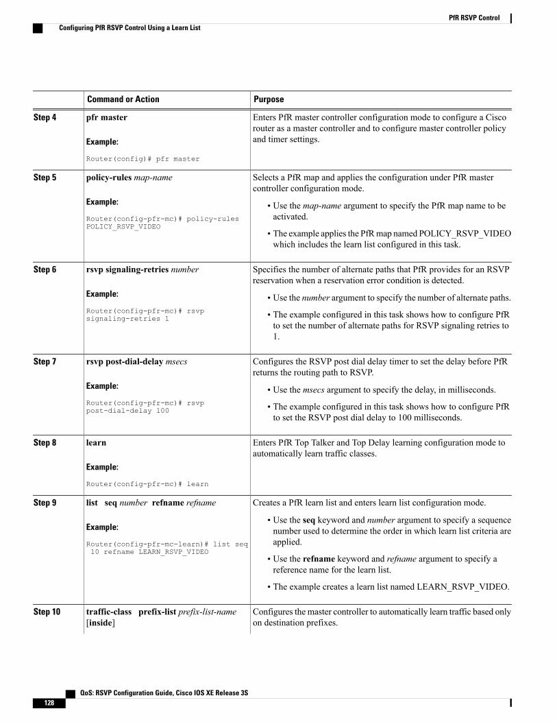
PurposeCommand or Action
Enters PfR master controller configuration mode to configure a Ciscorouter as a master controller and to configure master controller policyand timer settings.
pfr master
Example:
Router(config)# pfr master
Step 4
Selects a PfR map and applies the configuration under PfR mastercontroller configuration mode.
policy-rules map-name
Example:
Router(config-pfr-mc)# policy-rulesPOLICY_RSVP_VIDEO
Step 5
• Use the map-name argument to specify the PfR map name to beactivated.
• The example applies the PfRmap named POLICY_RSVP_VIDEOwhich includes the learn list configured in this task.
Specifies the number of alternate paths that PfR provides for an RSVPreservation when a reservation error condition is detected.
rsvp signaling-retries number
Example:
Router(config-pfr-mc)# rsvpsignaling-retries 1
Step 6
• Use the number argument to specify the number of alternate paths.
• The example configured in this task shows how to configure PfRto set the number of alternate paths for RSVP signaling retries to1.
Configures the RSVP post dial delay timer to set the delay before PfRreturns the routing path to RSVP.
rsvp post-dial-delay msecs
Example:
Router(config-pfr-mc)# rsvppost-dial-delay 100
Step 7
• Use the msecs argument to specify the delay, in milliseconds.
• The example configured in this task shows how to configure PfRto set the RSVP post dial delay to 100 milliseconds.
Enters PfR Top Talker and Top Delay learning configuration mode toautomatically learn traffic classes.
learn
Example:
Router(config-pfr-mc)# learn
Step 8
Creates a PfR learn list and enters learn list configuration mode.list seq number refname refnameStep 9
Example:
Router(config-pfr-mc-learn)# list seq10 refname LEARN_RSVP_VIDEO
• Use the seq keyword and number argument to specify a sequencenumber used to determine the order in which learn list criteria areapplied.
• Use the refname keyword and refname argument to specify areference name for the learn list.
• The example creates a learn list named LEARN_RSVP_VIDEO.
Configures the master controller to automatically learn traffic based onlyon destination prefixes.
traffic-class prefix-list prefix-list-name[inside]
Step 10
QoS: RSVP Configuration Guide, Cisco IOS XE Release 3S128
PfR RSVP ControlConfiguring PfR RSVP Control Using a Learn List
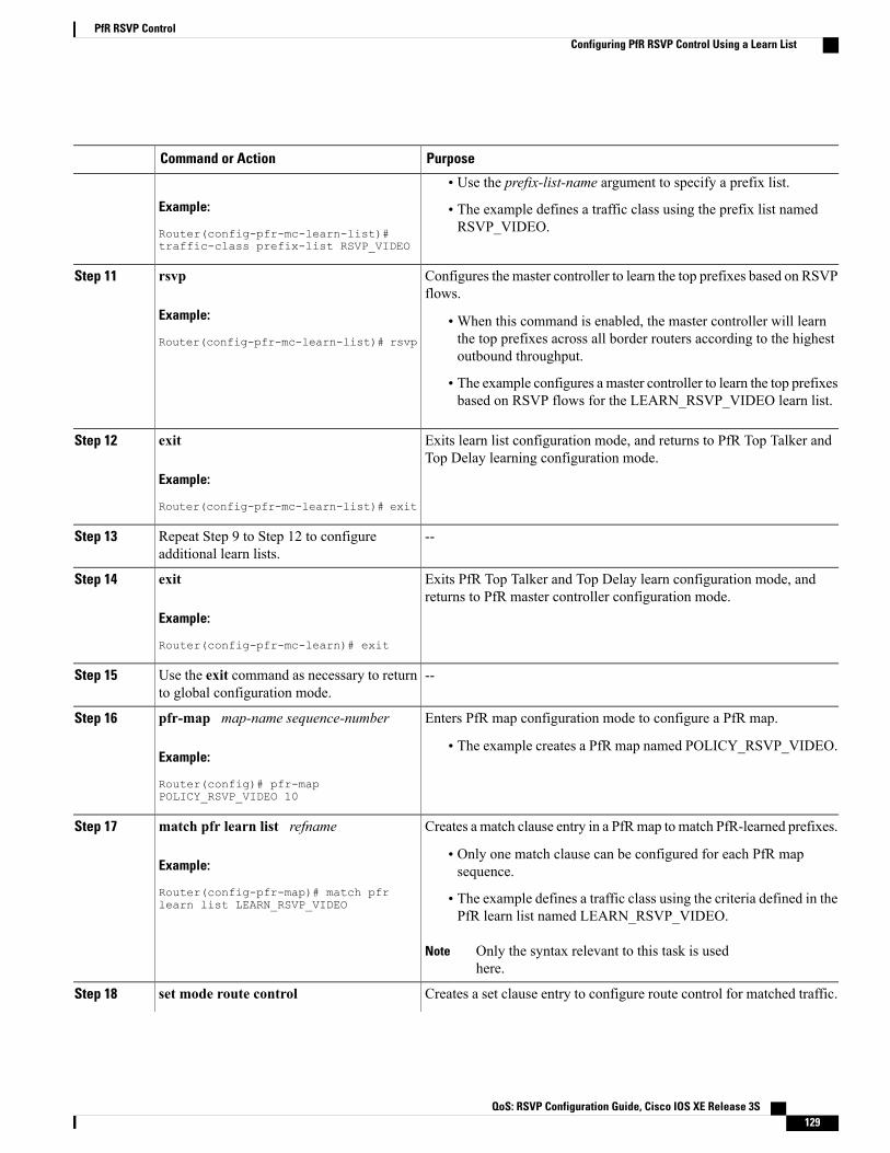
PurposeCommand or Action
Example:
Router(config-pfr-mc-learn-list)#traffic-class prefix-list RSVP_VIDEO
• Use the prefix-list-name argument to specify a prefix list.
• The example defines a traffic class using the prefix list namedRSVP_VIDEO.
Configures the master controller to learn the top prefixes based on RSVPflows.
rsvp
Example:
Router(config-pfr-mc-learn-list)# rsvp
Step 11
•When this command is enabled, the master controller will learnthe top prefixes across all border routers according to the highestoutbound throughput.
• The example configures a master controller to learn the top prefixesbased on RSVP flows for the LEARN_RSVP_VIDEO learn list.
Exits learn list configuration mode, and returns to PfR Top Talker andTop Delay learning configuration mode.
exit
Example:
Router(config-pfr-mc-learn-list)# exit
Step 12
--Repeat Step 9 to Step 12 to configureadditional learn lists.
Step 13
Exits PfR Top Talker and Top Delay learn configuration mode, andreturns to PfR master controller configuration mode.
exit
Example:
Router(config-pfr-mc-learn)# exit
Step 14
--Use the exit command as necessary to returnto global configuration mode.
Step 15
Enters PfR map configuration mode to configure a PfR map.pfr-map map-name sequence-numberStep 16
Example:
Router(config)# pfr-mapPOLICY_RSVP_VIDEO 10
• The example creates a PfR map named POLICY_RSVP_VIDEO.
Creates a match clause entry in a PfRmap to match PfR-learned prefixes.match pfr learn list refnameStep 17
Example:
Router(config-pfr-map)# match pfrlearn list LEARN_RSVP_VIDEO
• Only one match clause can be configured for each PfR mapsequence.
• The example defines a traffic class using the criteria defined in thePfR learn list named LEARN_RSVP_VIDEO.
Only the syntax relevant to this task is usedhere.
Note
Creates a set clause entry to configure route control for matched traffic.set mode route controlStep 18
QoS: RSVP Configuration Guide, Cisco IOS XE Release 3S 129
PfR RSVP ControlConfiguring PfR RSVP Control Using a Learn List

PurposeCommand or Action
Example:
Router(config-pfr-map)# set mode routecontrol
• In control mode, the master controller analyzes monitored prefixesand implements changes based on policy parameters.
Creates a set clause entry to specify the use of the equivalent-pathround-robin resolver.
set resolve equivalent-path-round-robin
Example:
Router(config-pfr-map)# set resolveequivalent-path-round-robin
Step 19
• In this task, the equivalent-path round-robin resolver is used tochoose between equivalent paths instead of the random resolver.
(Optional) Exits PfR map configuration mode and returns to privilegedEXEC mode.
end
Example:
Router(config-pfr-map)# end
Step 20
Displaying PfR RSVP Control InformationAlthough the PfR RSVP Control feature is configured on a master controller, the border routers actuallycollect the performance information, and there are show and debug commands available to display the RSVPinformation for both the master controller and border routers. The first few commands in this task are enteredon a master controller and, for the rest of the commands, there is a step to move to a border router throughwhich the application traffic is flowing. These show and debug commands can be entered in any order.
SUMMARY STEPS
1. enable2. show pfr master traffic-class [rsvp] [active | passive | status] [detail]3. show pfr master policy [sequence-number | policy-name | default | dynamic]4. debug pfr master rsvp5. Move to a border router through which the RSVP traffic is flowing.6. enable7. show pfr border rsvp8. show pfr border routes rsvp-cache9. debug pfr border rsvp
DETAILED STEPS
Step 1 enableEnables privileged EXEC mode. Enter your password if prompted.
QoS: RSVP Configuration Guide, Cisco IOS XE Release 3S130
PfR RSVP ControlDisplaying PfR RSVP Control Information

Example:
Router> enable
Step 2 show pfr master traffic-class [rsvp] [active | passive | status] [detail]This command is used to display information about PfR traffic classes that are learned as RSVP traffic classes.
Example:
Router# show pfr master traffic-class rsvp
OER Prefix Statistics:Pas - Passive, Act - Active, S - Short term, L - Long term, Dly - Delay (ms),P - Percentage below threshold, Jit - Jitter (ms),MOS - Mean Opinion ScoreLos - Packet Loss (packets-per-million), Un - Unreachable (flows-per-million),E - Egress, I - Ingress, Bw - Bandwidth (kbps), N - Not applicableU - unknown, * - uncontrolled, + - control more specific, @ - active probe all# - Prefix monitor mode is Special, & - Blackholed Prefix% - Force Next-Hop, ^ - Prefix is denied
DstPrefix Appl_ID Dscp Prot SrcPort DstPort SrcPrefixFlags State Time CurrBR CurrI/F Protocol
PasSDly PasLDly PasSUn PasLUn PasSLos PasLLos EBw IBwActSDly ActLDly ActSUn ActLUn ActSJit ActPMOS ActSLos ActLLos
--------------------------------------------------------------------------------10.1.0.10/32 N N tcp 75-75 75-75 10.1.0.12/32
INPOLICY @0 10.1.0.24 Tu24 PBRU U 0 0 0 0 0 01 1 0 0 N N N N
Step 3 show pfr master policy [sequence-number | policy-name | default | dynamic]This command is used to display policy information. The following example uses the dynamic keyword to display thepolicies dynamically created by provider applications. Note the RSVP configuration commands.
Example:
Router# show pfr master policy dynamic
Dynamic Policies:
proxy id 10.3.3.3sequence no. 18446744069421203465, provider id 1001, provider priority 65535host priority 65535, policy priority 101, Session id 9
backoff 90 90 90delay relative 50holddown 90periodic 0probe frequency 56mode route controlmode monitor bothmode select-exit goodloss relative 10jitter threshold 20mos threshold 3.60 percent 30unreachable relative 50next-hop not setforwarding interface not setresolve delay priority 11 variance 20resolve utilization priority 12 variance 20proxy id 10.3.3.3sequence no. 18446744069421269001, provider id 1001, provider priority 65535host priority 65535, policy priority 102, Session id 9
QoS: RSVP Configuration Guide, Cisco IOS XE Release 3S 131
PfR RSVP ControlDisplaying PfR RSVP Control Information
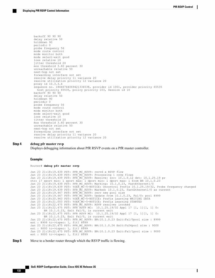
backoff 90 90 90delay relative 50holddown 90periodic 0probe frequency 56mode route controlmode monitor bothmode select-exit goodloss relative 10jitter threshold 20mos threshold 3.60 percent 30unreachable relative 50next-hop not setforwarding interface not setresolve delay priority 11 variance 20resolve utilization priority 12 variance 20proxy id 10.3.3.4sequence no. 18446744069421334538, provider id 1001, provider priority 65535host priority 65535, policy priority 103, Session id 10
backoff 90 90 90delay relative 50holddown 90periodic 0probe frequency 56mode route controlmode monitor bothmode select-exit goodloss relative 10jitter threshold 20mos threshold 3.60 percent 30unreachable relative 50next-hop not setforwarding interface not setresolve delay priority 11 variance 20resolve utilization priority 12 variance 20
Step 4 debug pfr master rsvpDisplays debugging information about PfR RSVP events on a PfR master controller.
Example:
Router# debug pfr master rsvp
Jan 23 21:18:19.439 PST: PFR_MC_RSVP: recvd a RSVP flowJan 23 21:18:19.439 PST: PFR_MC_RSVP: Processing 1 rsvp flowsJan 23 21:18:19.439 PST: PFR_MC_RSVP: Resolve: src: 10.1.0.12 dst: 10.1.25.19 proto: 17 sport min: 1 sport max: 1 dport min: 1 dport max: 1 from BR 10.1.0.23Jan 23 21:18:19.439 PST: PFR_MC_RSVP: Marking: 10.1.0.23, FastEthernet1/0Jan 23 21:18:19.439 PST: %OER_MC-5-NOTICE: Uncontrol Prefix 10.1.25.19/32, Probe frequency changedJan 23 21:18:19.439 PST: PFR_MC_RSVP: Marked: 10.1.0.23, FastEthernet1/0 as currentJan 23 21:18:19.467 PST: PFR_MC_RSVP: recv new pool sizeJan 23 21:18:19.467 PST: PFR_MC_RSVP: Update from 10.1.0.23, Fa1/0: pool 8999Jan 23 21:18:20.943 PST: %OER_MC-5-NOTICE: Prefix Learning WRITING DATAJan 23 21:18:21.003 PST: %OER_MC-5-NOTICE: Prefix Learning STARTEDJan 23 21:18:22.475 PST: PFR_MC_RSVP: RSVP resolver invokedJan 23 21:18:22.475 PST: PFR RSVP MC: 10.1.25.19/32 Appl 17 [1, 1][1, 1] 0:
BR 10.1.0.23, Exit Fa1/0, is current exitJan 23 21:18:22.475 PST: PFR RSVP MC: 10.1.25.19/32 Appl 17 [1, 1][1, 1] 0:
BR 10.1.0.23, Exit Fa1/0, is current exitJan 23 21:18:22.475 PST: PFR_MC_RSVP: BR:10.1.0.23 Exit:Fa1/0pool size : 8999est : 8999 tc->tspec: 1, fit: 8999Jan 23 21:18:22.475 PST: PFR_MC_RSVP: BR:10.1.0.24 Exit:Tu24pool size : 9000est : 9000 tc->tspec: 1, fit: 8999Jan 23 21:18:22.475 PST: PFR_MC_RSVP: BR:10.1.0.23 Exit:Fa1/1pool size : 9000est : 9000 tc->tspec: 1, fit: 8999
Step 5 Move to a border router through which the RSVP traffic is flowing.
QoS: RSVP Configuration Guide, Cisco IOS XE Release 3S132
PfR RSVP ControlDisplaying PfR RSVP Control Information
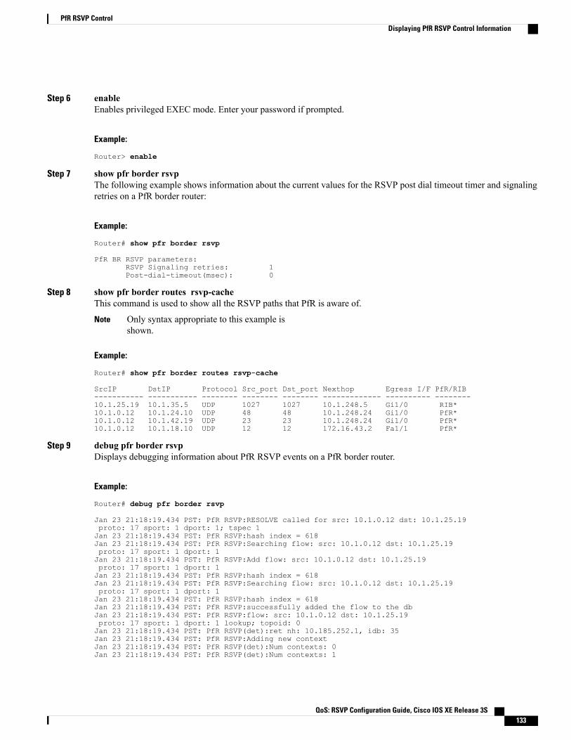
Step 6 enableEnables privileged EXEC mode. Enter your password if prompted.
Example:
Router> enable
Step 7 show pfr border rsvpThe following example shows information about the current values for the RSVP post dial timeout timer and signalingretries on a PfR border router:
Example:
Router# show pfr border rsvp
PfR BR RSVP parameters:RSVP Signaling retries: 1Post-dial-timeout(msec): 0
Step 8 show pfr border routes rsvp-cacheThis command is used to show all the RSVP paths that PfR is aware of.
Only syntax appropriate to this example isshown.
Note
Example:
Router# show pfr border routes rsvp-cache
SrcIP DstIP Protocol Src_port Dst_port Nexthop Egress I/F PfR/RIB----------- ----------- -------- -------- -------- ------------- ---------- --------10.1.25.19 10.1.35.5 UDP 1027 1027 10.1.248.5 Gi1/0 RIB*10.1.0.12 10.1.24.10 UDP 48 48 10.1.248.24 Gi1/0 PfR*10.1.0.12 10.1.42.19 UDP 23 23 10.1.248.24 Gi1/0 PfR*10.1.0.12 10.1.18.10 UDP 12 12 172.16.43.2 Fa1/1 PfR*
Step 9 debug pfr border rsvpDisplays debugging information about PfR RSVP events on a PfR border router.
Example:
Router# debug pfr border rsvp
Jan 23 21:18:19.434 PST: PfR RSVP:RESOLVE called for src: 10.1.0.12 dst: 10.1.25.19proto: 17 sport: 1 dport: 1; tspec 1Jan 23 21:18:19.434 PST: PfR RSVP:hash index = 618Jan 23 21:18:19.434 PST: PfR RSVP:Searching flow: src: 10.1.0.12 dst: 10.1.25.19proto: 17 sport: 1 dport: 1Jan 23 21:18:19.434 PST: PfR RSVP:Add flow: src: 10.1.0.12 dst: 10.1.25.19proto: 17 sport: 1 dport: 1Jan 23 21:18:19.434 PST: PfR RSVP:hash index = 618Jan 23 21:18:19.434 PST: PfR RSVP:Searching flow: src: 10.1.0.12 dst: 10.1.25.19proto: 17 sport: 1 dport: 1Jan 23 21:18:19.434 PST: PfR RSVP:hash index = 618Jan 23 21:18:19.434 PST: PfR RSVP:successfully added the flow to the dbJan 23 21:18:19.434 PST: PfR RSVP:flow: src: 10.1.0.12 dst: 10.1.25.19proto: 17 sport: 1 dport: 1 lookup; topoid: 0Jan 23 21:18:19.434 PST: PfR RSVP(det):ret nh: 10.185.252.1, idb: 35Jan 23 21:18:19.434 PST: PfR RSVP:Adding new contextJan 23 21:18:19.434 PST: PfR RSVP(det):Num contexts: 0Jan 23 21:18:19.434 PST: PfR RSVP(det):Num contexts: 1
QoS: RSVP Configuration Guide, Cisco IOS XE Release 3S 133
PfR RSVP ControlDisplaying PfR RSVP Control Information
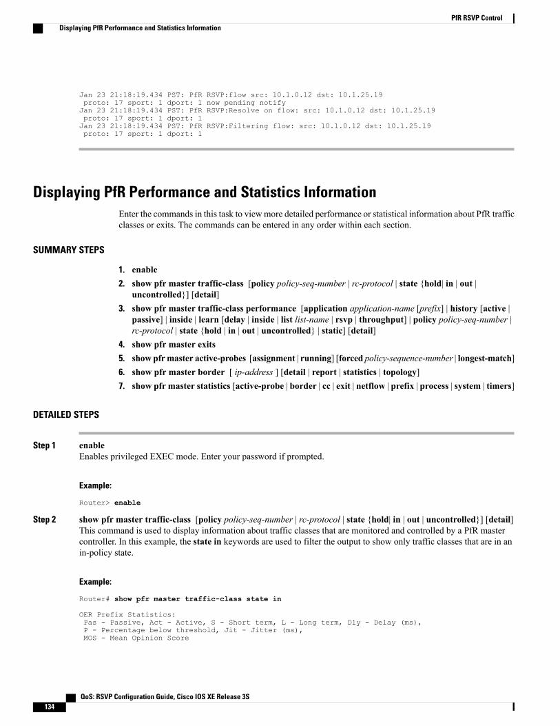
Jan 23 21:18:19.434 PST: PfR RSVP:flow src: 10.1.0.12 dst: 10.1.25.19proto: 17 sport: 1 dport: 1 now pending notifyJan 23 21:18:19.434 PST: PfR RSVP:Resolve on flow: src: 10.1.0.12 dst: 10.1.25.19proto: 17 sport: 1 dport: 1Jan 23 21:18:19.434 PST: PfR RSVP:Filtering flow: src: 10.1.0.12 dst: 10.1.25.19proto: 17 sport: 1 dport: 1
Displaying PfR Performance and Statistics InformationEnter the commands in this task to viewmore detailed performance or statistical information about PfR trafficclasses or exits. The commands can be entered in any order within each section.
SUMMARY STEPS
1. enable2. show pfr master traffic-class [policy policy-seq-number | rc-protocol | state {hold| in | out |
uncontrolled}] [detail]3. show pfr master traffic-class performance [application application-name [prefix] | history [active |
passive] | inside | learn [delay | inside | list list-name | rsvp | throughput] | policy policy-seq-number |rc-protocol | state {hold | in | out | uncontrolled} | static] [detail]
4. show pfr master exits5. show pfrmaster active-probes [assignment | running] [forced policy-sequence-number | longest-match]6. show pfr master border [ ip-address ] [detail | report | statistics | topology]7. show pfr master statistics [active-probe | border | cc | exit | netflow | prefix | process | system | timers]
DETAILED STEPS
Step 1 enableEnables privileged EXEC mode. Enter your password if prompted.
Example:
Router> enable
Step 2 show pfr master traffic-class [policy policy-seq-number | rc-protocol | state {hold| in | out | uncontrolled}] [detail]This command is used to display information about traffic classes that are monitored and controlled by a PfR mastercontroller. In this example, the state in keywords are used to filter the output to show only traffic classes that are in anin-policy state.
Example:
Router# show pfr master traffic-class state in
OER Prefix Statistics:Pas - Passive, Act - Active, S - Short term, L - Long term, Dly - Delay (ms),P - Percentage below threshold, Jit - Jitter (ms),MOS - Mean Opinion Score
QoS: RSVP Configuration Guide, Cisco IOS XE Release 3S134
PfR RSVP ControlDisplaying PfR Performance and Statistics Information

Los - Packet Loss (packets-per-million), Un - Unreachable (flows-per-million),E - Egress, I - Ingress, Bw - Bandwidth (kbps), N - Not applicableU - unknown, * - uncontrolled, + - control more specific, @ - active probe all# - Prefix monitor mode is Special, & - Blackholed Prefix% - Force Next-Hop, ^ - Prefix is denied
DstPrefix Appl_ID Dscp Prot SrcPort DstPort SrcPrefixFlags State Time CurrBR CurrI/F Protocol
PasSDly PasLDly PasSUn PasLUn PasSLos PasLLos EBw IBwActSDly ActLDly ActSUn ActLUn ActSJit ActPMOS ActSLos ActLLos
--------------------------------------------------------------------------------10.1.0.0/24 N N N N N N
INPOLICY 0 10.1.1.1 Et0/0 BGP14 14 0 0 0 0 78 9N N N N N N
10.2.0.0/24 N N N N N NINPOLICY 0 10.1.1.2 Et0/0 BGP
14 14 0 0 0 0 75 9N N N N N N
10.3.0.0/24 N N N N N NINPOLICY 0 10.1.1.3 Et0/0 BGP
14 14 0 0 0 0 77 9N N N N N N
10.4.0.0/24 N N N N N NINPOLICY 0 10.1.1.4 Et0/0 BGP
14 14 0 0 0 0 77 9N N N N N N
10.1.8.0/24 N N N N N NINPOLICY 0 10.1.1.3 Et0/0 BGP
14 14 62500 73359 0 0 5 1N N N N N N
10.1.1.0/24 N N N N N NINPOLICY 0 10.1.1.2 Et0/0 BGP
14 14 9635 9386 1605 1547 34 4N N N N N N
Step 3 show pfr master traffic-class performance [application application-name [prefix] | history [active | passive] | inside| learn [delay | inside | list list-name | rsvp | throughput] | policy policy-seq-number | rc-protocol | state {hold | in |out | uncontrolled} | static] [detail]This command displays performance information about traffic classes that are monitored and controlled by a PfR mastercontroller.
Only the syntax applicable to this example isshown.
Note
Example:The following output shows traffic-class performance history on current exits during the last 60 minutes.Router# show pfr master traffic-class performance history
Prefix: 10.70.0.0/16efix performance history recordsCurrent index 1, S_avg interval(min) 5, L_avg interval(min) 60
Age Border Interface OOP/RteChg ReasonsPas: DSum Samples DAvg PktLoss Unreach Ebytes Ibytes Pkts FlowsAct: Dsum Attempts DAvg Comps Unreach Jitter LoMOSCnt MOSCnt00:00:33 10.1.1.4 Et0/0Pas: 6466 517 12 2 58 3400299 336921 10499 2117Act: 0 0 0 0 0 N N N00:01:35 10.1.1.4 Et0/0Pas:15661 1334 11 4 157 4908315 884578 20927 3765
QoS: RSVP Configuration Guide, Cisco IOS XE Release 3S 135
PfR RSVP ControlDisplaying PfR Performance and Statistics Information
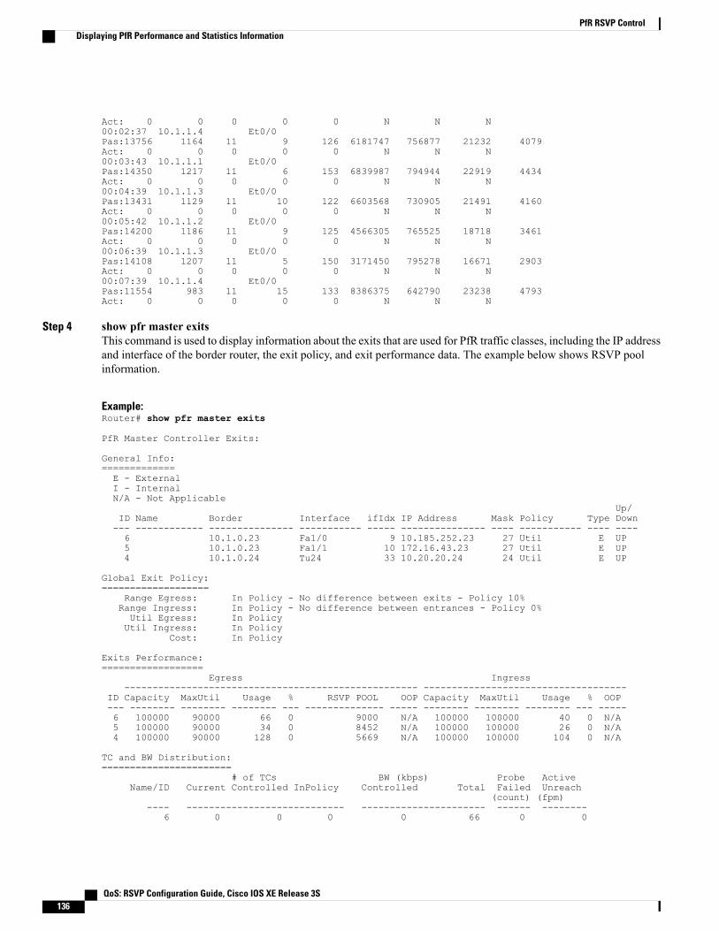
Act: 0 0 0 0 0 N N N00:02:37 10.1.1.4 Et0/0Pas:13756 1164 11 9 126 6181747 756877 21232 4079Act: 0 0 0 0 0 N N N00:03:43 10.1.1.1 Et0/0Pas:14350 1217 11 6 153 6839987 794944 22919 4434Act: 0 0 0 0 0 N N N00:04:39 10.1.1.3 Et0/0Pas:13431 1129 11 10 122 6603568 730905 21491 4160Act: 0 0 0 0 0 N N N00:05:42 10.1.1.2 Et0/0Pas:14200 1186 11 9 125 4566305 765525 18718 3461Act: 0 0 0 0 0 N N N00:06:39 10.1.1.3 Et0/0Pas:14108 1207 11 5 150 3171450 795278 16671 2903Act: 0 0 0 0 0 N N N00:07:39 10.1.1.4 Et0/0Pas:11554 983 11 15 133 8386375 642790 23238 4793Act: 0 0 0 0 0 N N N
Step 4 show pfr master exitsThis command is used to display information about the exits that are used for PfR traffic classes, including the IP addressand interface of the border router, the exit policy, and exit performance data. The example below shows RSVP poolinformation.
Example:Router# show pfr master exits
PfR Master Controller Exits:
General Info:=============E - ExternalI - InternalN/A - Not Applicable
Up/ID Name Border Interface ifIdx IP Address Mask Policy Type Down--- ------------ --------------- ----------- ----- --------------- ---- ----------- ---- ----6 10.1.0.23 Fa1/0 9 10.185.252.23 27 Util E UP5 10.1.0.23 Fa1/1 10 172.16.43.23 27 Util E UP4 10.1.0.24 Tu24 33 10.20.20.24 24 Util E UP
Global Exit Policy:===================
Range Egress: In Policy - No difference between exits - Policy 10%Range Ingress: In Policy - No difference between entrances - Policy 0%Util Egress: In PolicyUtil Ingress: In Policy
Cost: In Policy
Exits Performance:==================
Egress Ingress---------------------------------------------------- ------------------------------------
ID Capacity MaxUtil Usage % RSVP POOL OOP Capacity MaxUtil Usage % OOP--- -------- -------- -------- --- -------------- ----- -------- -------- -------- --- -----6 100000 90000 66 0 9000 N/A 100000 100000 40 0 N/A5 100000 90000 34 0 8452 N/A 100000 100000 26 0 N/A4 100000 90000 128 0 5669 N/A 100000 100000 104 0 N/A
TC and BW Distribution:=======================
# of TCs BW (kbps) Probe ActiveName/ID Current Controlled InPolicy Controlled Total Failed Unreach
(count) (fpm)---- ---------------------------- ---------------------- ------ --------
6 0 0 0 0 66 0 0
QoS: RSVP Configuration Guide, Cisco IOS XE Release 3S136
PfR RSVP ControlDisplaying PfR Performance and Statistics Information

5 548 548 548 0 34 0 04 3202 3202 3202 0 128 0 0
Exit Related TC Stats:======================
Priorityhighest nth------------------
Number of TCs with range: 0 0Number of TCs with util: 0 0Number of TCs with cost: 0 0
Total number of TCs: 3800
Step 5 show pfr master active-probes [assignment | running] [forced policy-sequence-number | longest-match]The following example shows the status of all created or in-progress probes.
Example:
Router# show pfr master active-probes running
PfR Master Controller running probes:
Border Interface Type Target TPort Codec Freq Forced Pkts DSCP(PolSeq)
-------------- ----------- -------- -------------- ----- -------- ---- ------ ---- ----10.100.100.200 Ethernet1/0 tcp-conn 10.100.200.100 65535 g711alaw 10 20 100 ef10.2.2.3 Ethernet1/0 tcp-conn 10.1.5.1 23 N 56 10 1 defa10.1.1.1 Ethernet1/0 tcp-conn 10.1.5.1 23 N 30 N 1 defa10.1.1.2 Ethernet1/0 tcp-conn 10.1.2.1 23 N 56 N 1 defa10.2.2.3 Ethernet1/0 tcp-conn 10.1.2.1 23 N 56 N 1 defa10.1.1.1 Ethernet1/0 tcp-conn 10.1.2.1 23 N 56 N 1 defa
Step 6 show pfr master border [ ip-address ] [detail | report | statistics | topology]Entered on a master controller, this command displays statistics about all the border routers.
Example:
Router# show pfr master border statistics
PFR Master Controller BorderMC Version: 2.3Keepalive : 5 secondKeepalive : DISABLED
LastBorder Status Up/Down UpTime AuthFail Receive Version---------------- ------ ------- -------- -------- -------- -------10.200.200.200 ACTIVE UP 03:12:12 0 00:00:04 2.210.1.1.2 ACTIVE UP 03:10:53 0 00:00:10 2.210.1.1.1 ACTIVE UP 03:12:12 0 00:01:00 2.2
Border Connection Statistics==============================
Bytes Bytes Msg Msg Sec BufBorder Sent Recvd Sent Recvd Bytes Used---------------- -------------- ------------- ------ ------ ----------10.200.200.200 345899 373749 5 10 010.1.1.2 345899 373749 5 10 010.1.1.1 345899 373749 5 10 0
Socket Invalid ContextBorder Closed Message Not Found---------------- ------ ------- ---------
QoS: RSVP Configuration Guide, Cisco IOS XE Release 3S 137
PfR RSVP ControlDisplaying PfR Performance and Statistics Information
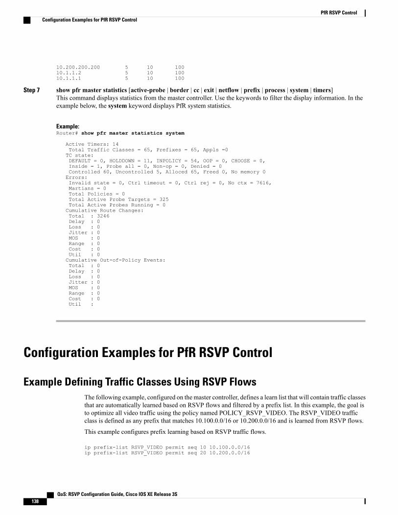
10.200.200.200 5 10 10010.1.1.2 5 10 10010.1.1.1 5 10 100
Step 7 show pfr master statistics [active-probe | border | cc | exit | netflow | prefix | process | system | timers]This command displays statistics from the master controller. Use the keywords to filter the display information. In theexample below, the system keyword displays PfR system statistics.
Example:Router# show pfr master statistics system
Active Timers: 14Total Traffic Classes = 65, Prefixes = 65, Appls =0TC state:DEFAULT = 0, HOLDDOWN = 11, INPOLICY = 54, OOP = 0, CHOOSE = 0,Inside = 1, Probe all = 0, Non-op = 0, Denied = 0Controlled 60, Uncontrolled 5, Alloced 65, Freed 0, No memory 0Errors:Invalid state = 0, Ctrl timeout = 0, Ctrl rej = 0, No ctx = 7616,Martians = 0Total Policies = 0Total Active Probe Targets = 325Total Active Probes Running = 0Cumulative Route Changes:Total : 3246Delay : 0Loss : 0Jitter : 0MOS : 0Range : 0Cost : 0Util : 0Cumulative Out-of-Policy Events:Total : 0Delay : 0Loss : 0Jitter : 0MOS : 0Range : 0Cost : 0Util :
Configuration Examples for PfR RSVP Control
Example Defining Traffic Classes Using RSVP FlowsThe following example, configured on the master controller, defines a learn list that will contain traffic classesthat are automatically learned based on RSVP flows and filtered by a prefix list. In this example, the goal isto optimize all video traffic using the policy named POLICY_RSVP_VIDEO. The RSVP_VIDEO trafficclass is defined as any prefix that matches 10.100.0.0/16 or 10.200.0.0/16 and is learned from RSVP flows.
This example configures prefix learning based on RSVP traffic flows.
ip prefix-list RSVP_VIDEO permit seq 10 10.100.0.0/16ip prefix-list RSVP_VIDEO permit seq 20 10.200.0.0/16
QoS: RSVP Configuration Guide, Cisco IOS XE Release 3S138
PfR RSVP ControlConfiguration Examples for PfR RSVP Control

pfr masterpolicy-rules POLICY_RSVP_VIDEOrsvp signaling-retries 1rsvp post-dial-delay 100learnlist seq 10 refname LEARN_RSVP_VIDEOtraffic-class prefix-list RSVP_VIDEOrsvpexitexitpfr-map POLICY_RSVP_VIDEO 10match learn list LEARN_RSVP_VIDEOset mode route controlset resolve equivalent-path-round-robinend
Additional ReferencesRelated Documents
Document TitleRelated Topic
Cisco IOS Master Command List, All ReleasesCisco IOS commands
Cisco IOS PerformanceRouting CommandReferenceCisco PfR commands: complete command syntax,command mode, command history, defaults, usageguidelines, and examples
“Configuring Basic Performance Routing” moduleBasic PfR configuration
Configuring NetFlow and NetFlow Data ExportNetFlow and NetFlow data export
PfR:HomePfR home page with links to PfR-related content onour DocWiki collaborative environment
RFCs
TitleRFC
Cisco Systems NetFlow Services Export Version 9RFC 3954
QoS: RSVP Configuration Guide, Cisco IOS XE Release 3S 139
PfR RSVP ControlAdditional References

Technical Assistance
LinkDescription
http://www.cisco.com/cisco/web/support/index.htmlThe Cisco Support and Documentation websiteprovides online resources to download documentation,software, and tools. Use these resources to install andconfigure the software and to troubleshoot and resolvetechnical issues with Cisco products and technologies.Access to most tools on the Cisco Support andDocumentation website requires a Cisco.com user IDand password.
Feature Information for PfR RSVP ControlThe following table provides release information about the feature or features described in this module. Thistable lists only the software release that introduced support for a given feature in a given software releasetrain. Unless noted otherwise, subsequent releases of that software release train also support that feature.
Use Cisco Feature Navigator to find information about platform support and Cisco software image support.To access Cisco Feature Navigator, go to www.cisco.com/go/cfn. An account on Cisco.com is not required.
Table 8: Feature Information for PfR RSVP Control
Feature InformationReleasesFeature Name
The PfR RSVP Control featureprovides support for optimizingRSVP flows usingapplication-aware PfR techniques.
The following commands wereintroduced or modified by thisfeature: debug pfr border rsvp,debug pfr master rsvp, rsvp(PfR), rsvp post-dial-delay, rsvpsignaling-retries, resolve (PfR),set resolve (PfR), show pfrborder rsvp, show pfr borderroutes, show pfr masteractive-probes, show pfr masterborder, show pfr master exits,show pfrmaster policy, show pfrmaster statistics, show pfrmastertraffic-class, and show pfrmastertraffic-class performance.
Cisco IOS XE Release 3.4SPfR RSVP Control
QoS: RSVP Configuration Guide, Cisco IOS XE Release 3S140
PfR RSVP ControlFeature Information for PfR RSVP Control

C H A P T E R 9RSVP over UDP
The Resource Reservation Protocol (RSVP) over UDP feature provides the capability for routers to enableneighbor routers to process and send RSVP control packets over UDP.With the implementation of the RSVPover UDP feature, the RSVP protocol stack is enhanced to support processing of RSVP control messagesover UDP and raw IP.
• Finding Feature Information, page 141
• Prerequisites for RSVP Over UDP , page 141
• Information About RSVP over UDP, page 142
• How to Configure RSVP over UDP, page 142
• Configuration examples for RSVP over UDP, page 144
• Additional References, page 145
• Feature Information for RSVP over UDP , page 145
Finding Feature InformationYour software release may not support all the features documented in this module. For the latest caveats andfeature information, see Bug Search Tool and the release notes for your platform and software release. Tofind information about the features documented in this module, and to see a list of the releases in which eachfeature is supported, see the feature information table at the end of this module.
Use Cisco Feature Navigator to find information about platform support and Cisco software image support.To access Cisco Feature Navigator, go to www.cisco.com/go/cfn. An account on Cisco.com is not required.
Prerequisites for RSVP Over UDP• You must enable RSVP before you enable the RSVP over UDP feature.
• The RSVP stack running on the client host must support sending and receiving the RSVP control messageswith the first hop routers they are connected to.
QoS: RSVP Configuration Guide, Cisco IOS XE Release 3S 141
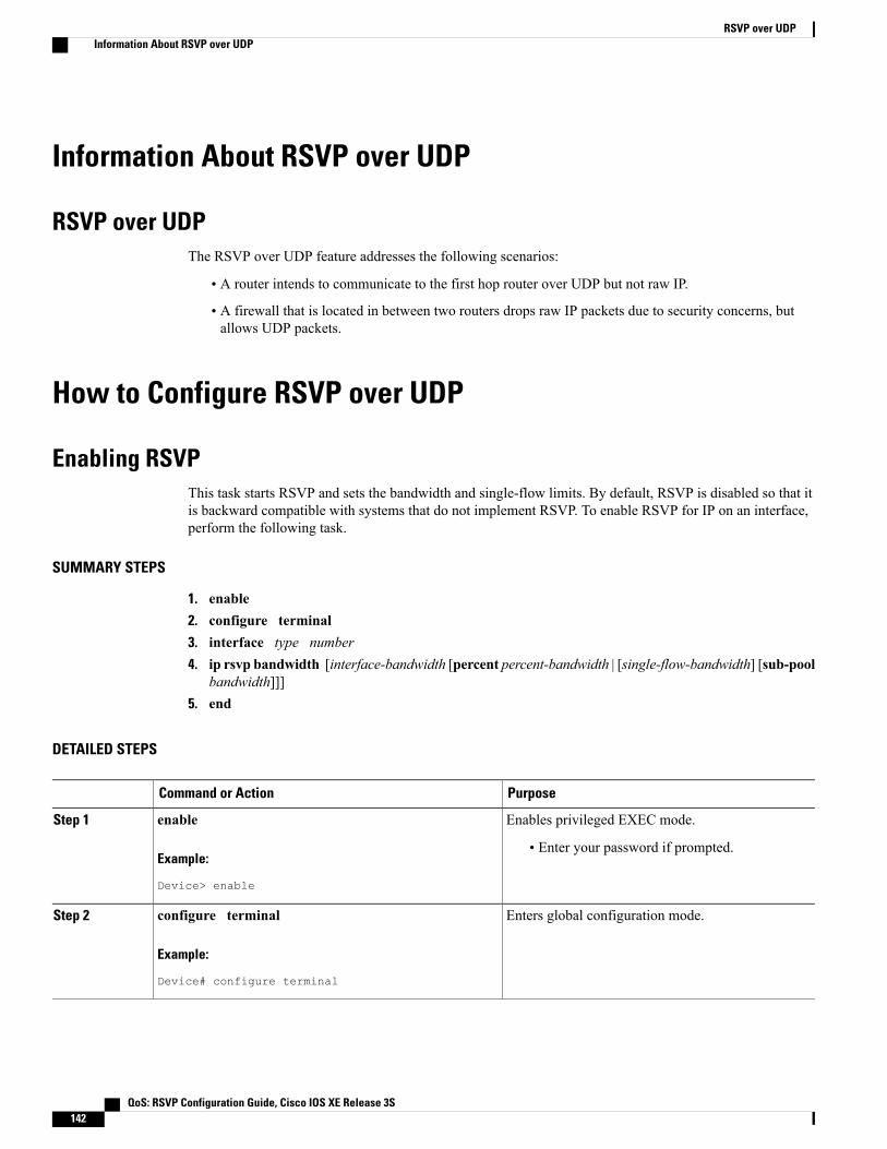
Information About RSVP over UDP
RSVP over UDPThe RSVP over UDP feature addresses the following scenarios:
• A router intends to communicate to the first hop router over UDP but not raw IP.
• A firewall that is located in between two routers drops raw IP packets due to security concerns, butallows UDP packets.
How to Configure RSVP over UDP
Enabling RSVPThis task starts RSVP and sets the bandwidth and single-flow limits. By default, RSVP is disabled so that itis backward compatible with systems that do not implement RSVP. To enable RSVP for IP on an interface,perform the following task.
SUMMARY STEPS
1. enable2. configure terminal3. interface type number4. ip rsvp bandwidth [interface-bandwidth [percent percent-bandwidth | [single-flow-bandwidth] [sub-pool
bandwidth]]]5. end
DETAILED STEPS
PurposeCommand or Action
Enables privileged EXEC mode.enableStep 1
Example:
Device> enable
• Enter your password if prompted.
Enters global configuration mode.configure terminal
Example:
Device# configure terminal
Step 2
QoS: RSVP Configuration Guide, Cisco IOS XE Release 3S142
RSVP over UDPInformation About RSVP over UDP

PurposeCommand or Action
Configures the specified interface and enters interfaceconfiguration mode.
interface type number
Example:
Device(config)# interface fastethernet 0/1
Step 3
Enables RSVP for IP on an interface.ip rsvp bandwidth [interface-bandwidth [percentpercent-bandwidth | [single-flow-bandwidth] [sub-poolbandwidth]]]
Step 4
Example:
Device(config-if)# ip rsvp bandwidth 23 54
Exits interface configuration mode and returns toprivileged EXEC mode.
end
Example:
Device(config-if)# end
Step 5
Configuring RSVP over UDPTo enable RSVP over UDP, perform the following task:
SUMMARY STEPS
1. enable2. configure terminal3. ip rsvp udp neighbor neighbor-IP-address router [vrf vrf-name]4. end
DETAILED STEPS
PurposeCommand or Action
Enables privileged EXEC mode.enableStep 1
Example:Device> enable
• Enter your password if prompted.
QoS: RSVP Configuration Guide, Cisco IOS XE Release 3S 143
RSVP over UDPConfiguring RSVP over UDP

PurposeCommand or Action
Enters global configuration mode.configure terminal
Example:Device# configure terminal
Step 2
Configures the RSVP over UDP feature for theneighbor router.
ip rsvp udp neighbor neighbor-IP-address router [vrfvrf-name]
Example:Device(config)# ip rsvp udp neighbor 10.1.1.1router vrf vrf-1
Step 3
Returns to privileged EXEC mode.end
Example:
Device(config)# end
Step 4
Configuration examples for RSVP over UDP
Example: Enabling RSVPThe following example shows how to enable RSVP for IP on an interface:
enableconfigure terminalinterface fastethernet 0/1ip rsvp bandwidth 23 54end
Example: Configuring RSVP over UDPThe following example shows how to configure the RSVP over UDP feature on a neighbor router:
enableconfigure terminalip rsvp udp neighbor 10.1.1.1 router vrf vrf-1end
QoS: RSVP Configuration Guide, Cisco IOS XE Release 3S144
RSVP over UDPConfiguration examples for RSVP over UDP
Additional ReferencesRelated Documents
Document TitleRelated Topic
Master Command List, AllReleases
Cisco IOS commands
Quality of Service SolutionsCommand Reference
RSVP commands
Signaling OverviewOverview on RSVP
Standards and RFCs
TitleStandard/RFC
RSVP—Version 1 Function SpecificationRFC 2205
RSVP—Version 1 Message Processing RulesRFC 2209
Technical Assistance
LinkDescription
http://www.cisco.com/cisco/web/support/index.htmlThe Cisco Support and Documentation websiteprovides online resources to download documentation,software, and tools. Use these resources to install andconfigure the software and to troubleshoot and resolvetechnical issues with Cisco products and technologies.Access to most tools on the Cisco Support andDocumentation website requires a Cisco.com user IDand password.
Feature Information for RSVP over UDPThe following table provides release information about the feature or features described in this module. Thistable lists only the software release that introduced support for a given feature in a given software releasetrain. Unless noted otherwise, subsequent releases of that software release train also support that feature.
Use Cisco Feature Navigator to find information about platform support and Cisco software image support.To access Cisco Feature Navigator, go to www.cisco.com/go/cfn. An account on Cisco.com is not required.
QoS: RSVP Configuration Guide, Cisco IOS XE Release 3S 145
RSVP over UDPAdditional References

Table 9: Feature Information for RSVP over UDP
Feature InformationReleasesFeature Name
The RSVP over UDP featureallows a router to enable a neighborrouter to process and send RSVPcontrol packets over UDP.
The following commands wereintroduced or modified: ip rsvpudp neighbor.
15.2(4)M
15.4(1)S
XE 3.11.0 S
RSVP over UDP
QoS: RSVP Configuration Guide, Cisco IOS XE Release 3S146
RSVP over UDPFeature Information for RSVP over UDP

I N D E X
B
benefits 81, 97
C
configuration 99verifying 99
V
verifying 86configuration 86
QoS: RSVP Configuration Guide, Cisco IOS XE Release 3S IN-1
QoS: RSVP Configuration Guide, Cisco IOS XE Release 3SIN-2
Index