PWW Bandpass Filter for 60 GHz Band Based on 2D …ap-s.ei.tuat.ac.jp/isapx/2016/pdf/3A2-5.pdfPWW...
2
PWW Bandpass Filter for 60 GHz Band Based on 2D MoM Design Optimization Ryohei Hosono, Yusuke Uemichi, Osamu Nukaga, Xu Han, and Ning Guan Fujikura Ltd. 1440, Mutsuzaki, Sakura, Chiba, JAPAN Abstract - In this paper, a bandpass filter (BPF) at 60 GHz band based on new design procedure is presented. The BPF is constructed by quartz-based post-wall waveguide (PWW) due to its lower dielectric loss. Filter design is achieved by optimization theory and burden for design is reduced by modeling filter as two dimensional structure. The 2D model is analyzed by using the method of moment (MoM) with global basis function. Validity is shown by a reasonable agreement between S-parameters for 2D model and those for 3D model. Index Terms — Bandpass filter, 60 GHz band, PWW, MoM 1. Introduction Recently, a special attention is given to 60 GHz band radio application by a demand for high speed and huge capacity wireless network. 60 GHz band possesses advantages in unlicensed bandwidth at 60 GHz band up to 9 GHz [1]-[2]. For applying 60 GHz band to such wireless communication, millimeter-wave circuits are required to have low loss, low cost fabrication and broadband operation. Additionally, integration of circuits with other devices such as antenna is also needed by a so called antenna-in-package method. In this paper, a design for bandpass filter (BPF) at 60 GHz band is presented. The BPF is constructed by post-wall waveguide (PWW) on quartz substrate which has lower dielectric loss [3]. Generally, the BPF is designed based on the cascaded impedance inverters as described in [4]. By using this design method, there is difference in frequency characteristics between filter on cascaded inverters and optimized one. It is cumbersome and time-consuming to optimize the filter even though circuit parameters for filter design are identified. In this investigation, for design efficiency, PWW BPF is designed as two dimensional model and optimized theory are employed. The 2D model is analyzed by using the moment method (MoM) with global basis function [5]. A comparison between 2D model and 3D model is done and a PWW-BPF with microstrip line (MSL) transition is also analyzed and compared. Reasonable agreement is obtained between them. 2. Formulation Based on the reference [5], PWW is modeled as conductive circular cylinder in dielectric media whose height is infinity as shown in Fig. 1. In this assumption, scattered field with TE 10 mode incidence can be expressed as: ( ) = − 0 0 4 ∮ 0 (2) ( 0 | − ′|) ( ′ ) ′ (1) where k 0 is a wavenumber and Z 0 is intrinsic impedance in free space. H 0 (2) is the Hankel function of the second kind of 0-th order. Vectors and ' denote observation point and source point. As the filter characteristics are evaluated by using frequency response of plane wave excitation, an incident electric field is described by: = − 0 ( cos 0 + sin 0 ) (2) For obtaining scattered field by solving the integral equation (1) as the method of moment (MoM), current density is expanded with global basis function: ( ′) = ∑ − =− (3) where a n is an unknown coefficient. The global basis function reduces calculation load due to its small number of coefficient with preciseness. Fig. 1. Scattering problem for conductive circular cylinder. 3. Filter Structure and Design Figure 2 shows the structure of PWW BPF. The BPF consists of a detection part for standing wave ratio (SWR) of electric field and filter part with iris as depicted in [6]. The SWR detection part observes reflected field from filter and its length is long enough to calculate reflectance precisely. Fig. 2. Structure of proposed PWW-BPF. To decide the dimension of the BPF for appropriate response of filter, genetic algorithm (GA) optimization is applied [8]. In the GA optimization to the PWW BPF, a crossover process is done by exchanging position of the iris between BPF individuals and a mutation process is carried out by slight change on position of the BPF. A fitness 0 0 E z 0 x y a E z SWR detection part Filter part Proceedings of ISAP2016, Okinawa, Japan Copyright ©2016 by IEICE 3A2-5 552
Transcript of PWW Bandpass Filter for 60 GHz Band Based on 2D …ap-s.ei.tuat.ac.jp/isapx/2016/pdf/3A2-5.pdfPWW...
PWW Bandpass Filter for 60 GHz Band Based on
2D MoM Design Optimization
Ryohei Hosono, Yusuke Uemichi, Osamu Nukaga, Xu Han, and Ning Guan Fujikura Ltd.
1440, Mutsuzaki, Sakura, Chiba, JAPAN
Abstract - In this paper, a bandpass filter (BPF) at 60 GHz
band based on new design procedure is presented. The BPF is constructed by quartz-based post-wall waveguide (PWW) due to its lower dielectric loss. Filter design is achieved by
optimization theory and burden for design is reduced by modeling filter as two dimensional structure. The 2D model is analyzed by using the method of moment (MoM) with global
basis function. Validity is shown by a reasonable agreement between S-parameters for 2D model and those for 3D model.
Index Terms — Bandpass filter, 60 GHz band, PWW, MoM
1. Introduction
Recently, a special attention is given to 60 GHz band radio
application by a demand for high speed and huge capacity
wireless network. 60 GHz band possesses advantages in
unlicensed bandwidth at 60 GHz band up to 9 GHz [1]-[2].
For applying 60 GHz band to such wireless communication,
millimeter-wave circuits are required to have low loss, low
cost fabrication and broadband operation. Additionally,
integration of circuits with other devices such as antenna is
also needed by a so called antenna-in-package method.
In this paper, a design for bandpass filter (BPF) at 60 GHz
band is presented. The BPF is constructed by post-wall
waveguide (PWW) on quartz substrate which has lower
dielectric loss [3]. Generally, the BPF is designed based on
the cascaded impedance inverters as described in [4]. By
using this design method, there is difference in frequency
characteristics between filter on cascaded inverters and
optimized one. It is cumbersome and time-consuming to
optimize the filter even though circuit parameters for filter
design are identified. In this investigation, for design
efficiency, PWW BPF is designed as two dimensional model
and optimized theory are employed. The 2D model is
analyzed by using the moment method (MoM) with global
basis function [5]. A comparison between 2D model and 3D
model is done and a PWW-BPF with microstrip line (MSL)
transition is also analyzed and compared. Reasonable
agreement is obtained between them.
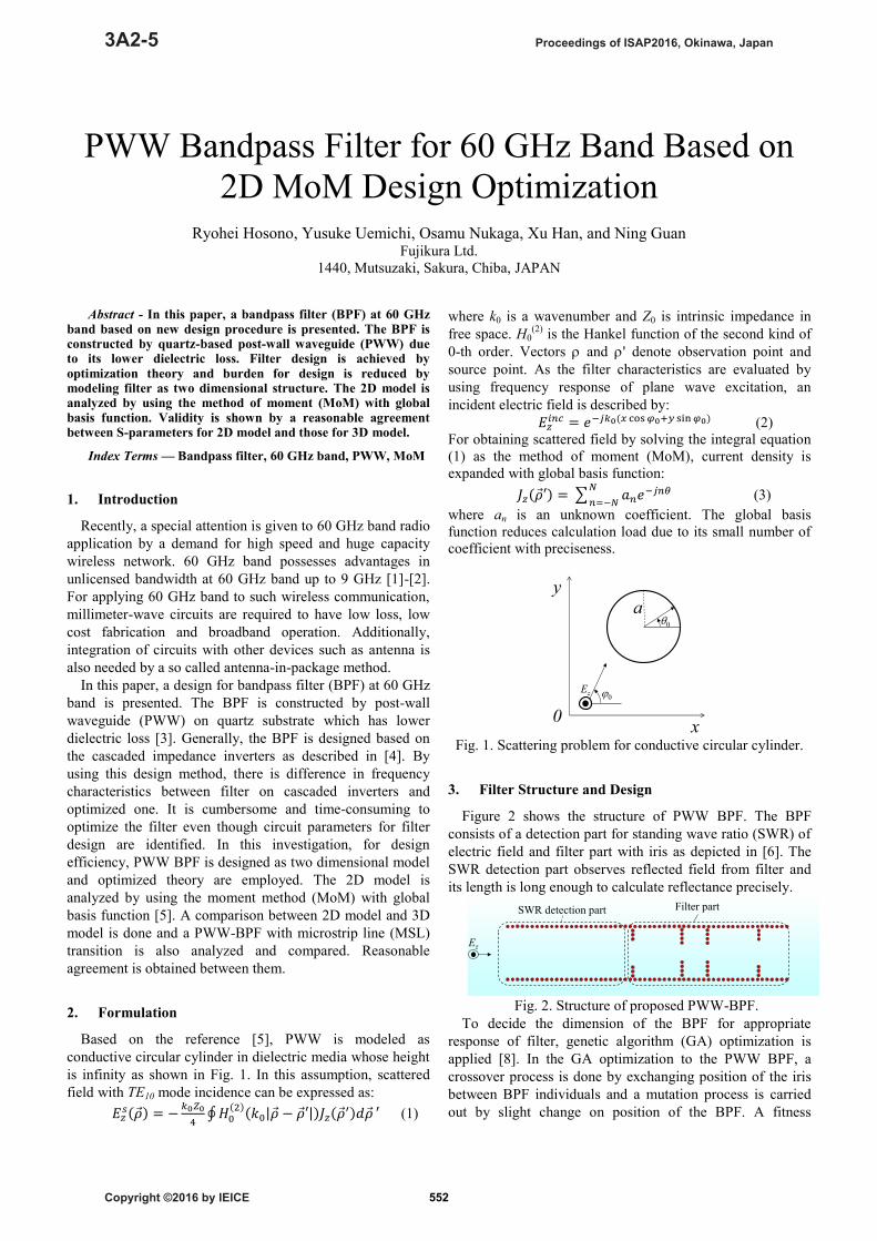
2. Formulation
Based on the reference [5], PWW is modeled as
conductive circular cylinder in dielectric media whose height
is infinity as shown in Fig. 1. In this assumption, scattered
field with TE10 mode incidence can be expressed as:
𝐸𝑧𝑠(�⃗�) = −
𝑘0𝑍0
4∮ 𝐻0
(2)(𝑘0|�⃗� − �⃗�′|)𝐽𝑧(�⃗�′)𝑑�⃗� ′ (1)
where k0 is a wavenumber and Z0 is intrinsic impedance in
free space. H0(2)
is the Hankel function of the second kind of
0-th order. Vectors and ' denote observation point and
source point. As the filter characteristics are evaluated by
using frequency response of plane wave excitation, an
incident electric field is described by:
𝐸𝑧𝑖𝑛𝑐 = 𝑒−𝑗𝑘0(𝑥 cos 𝜑0+𝑦 sin 𝜑0) (2)
For obtaining scattered field by solving the integral equation
(1) as the method of moment (MoM), current density is
expanded with global basis function:
𝐽𝑧(�⃗�′) = ∑ 𝑎𝑛𝑒−𝑗𝑛𝜃 𝑁
𝑛=−𝑁 (3)
where an is an unknown coefficient. The global basis
function reduces calculation load due to its small number of
coefficient with preciseness.
Fig. 1. Scattering problem for conductive circular cylinder.
3. Filter Structure and Design
Figure 2 shows the structure of PWW BPF. The BPF
consists of a detection part for standing wave ratio (SWR) of
electric field and filter part with iris as depicted in [6]. The
SWR detection part observes reflected field from filter and
its length is long enough to calculate reflectance precisely.
Fig. 2. Structure of proposed PWW-BPF.
To decide the dimension of the BPF for appropriate
response of filter, genetic algorithm (GA) optimization is
applied [8]. In the GA optimization to the PWW BPF, a
crossover process is done by exchanging position of the iris
between BPF individuals and a mutation process is carried
out by slight change on position of the BPF. A fitness
0
0Ez
0
x
ya
Ez
SWR detection part Filter part
Proceedings of ISAP2016, Okinawa, Japan
Copyright ©2016 by IEICE
3A2-5
552

function is described by using a summation of reflectance
and transmittance at pass and stop bands with weighted
coefficients for the optimization. It is because specifications
for reflection and transmission such as bandwidth and
magnitude are different from each other.
4. Performance Evaluation
To show the validity of proposed design, 3D simulation
model whose dimensions are optimized by 2D-MoM and GA
is analyzed and compared with each other. In this design
optimization, 3 dB bandwidth for |S21| and 10 dB bandwidth
for |S11| are set to be 7 GHz from 57-64 GHz. The simulation
is done by HFSSTM
. Figure 3 shows simulation model of
PWW BPF. The GCPW-PWW transition used in [9] is
connected to one of PWW BPF for measuring RF probe. The
dimensions of GCPW and tapered MSL are also optimized
for impedance matching to PWW.
Figure 4 shows S-parameters for BPF model by MoM and
BPF by HFSS. The BPF of HFSS is modeled without
GCPW-PWW transition. Good agreement is obtained in both
|S11| and |S21| so that precision of the proposed 2D-MoM is
demonstrated. Figure 5 also shows simulated S-parameters
for HFSS models of with and without transition. Reasonable
agreements in bandwidth and position of poles are obtained.
An insertion loss at 60 GHz is 2.3 dB and 3 dB bandwidth is
from 57.7-62 GHz in the BPF with transition. An increase of
the insertion loss in the BPF with transition is due to
propagation loss of the transitions and a decrease of
bandwidth is due to the mismatch of impedance between the
BPF and transition.
Fig. 3. Simulation model of PWW-BPFs with and without
transition.
Fig. 4. S-parameters for simulation models of MoM and
HFSS without transition.
Fig. 5. S-parameters for HFSS models of with and without
transition.
5. Conclusion
A post-wall waveguide based bandpass filter at 60 GHz
band is designed by a new optimization procedure. A 2D
model is applied and analyzed with the method of moment
for the design optimization. The appropriate method is
finally demonstrated by fairly good agreement on S-
parameters between 2D- and 3D-models. Additionally, a
filter model optimized by the proposed design procedure has
been fabricated and measured.
References
[1] Status of Project IEEE 802.11ad-Very High Throughput in 60GHz,
URL: http://www.ieee802.org/11/Reports/tgad_update.htm
[2] IEEE 802.15 WPAN Millimeter Wave Alternative PHY Task Group 3c (TG3c),
URL: http://www.ieee802.org/15/pub/TG3c_contributions.html
[3] Y. Uemichi, O. Nukaga, R. Hosono, N. Guan, J. Hirokawa, and M. Ando, “An ultra low-loss silica-based transformer between microstrip
line and post-wall waveguide for millimeter-wave antenna-in-
package applications,” Proc., IEEE MTT-S, pp.1-3, Tampa, FL, USA, June 2014.
[4] G. L. Matthaei, L. Young, and E. M. T. Jones, Microwave Filters, Impedance-Matching Networks, and Coupling Structures. Norwood,
MA: Artech House, 1980.
[5] K. Yashiro, “Global base approach to scattering by conducting circular cylinders,” Proc. of ICEAA, pp. 1453–1456, Torino, Italy,
Sept. 2013.
[6] D. Zelenchuk and V. Fusco, “Low insertion loss substrate integrated waveguide quasi-elliptic filters for V-band wireless personal area
network applications,” IET Microwaves, Antennas and Propagat., vol.
5, no. 8, pp. 921-927, 2011. [7] Y. Uemichi, O. Nukaga, K. Nakamura, X. Han, R. Hosono, N. Guan,
and S. Amakawa, “Compact and low-loss bandpass filter realized in
silica-based post-wall waveguide for 60-GHz applications,” Proc., IEEE MTT-S, pp. 1-3, Phoenix, AZ, May 2015.
[8] X. S. Yang, K. T. Ng, S. H. Yeung, and K. F. Man, “Jumping genes
multiobjective optimization scheme for planar monopole ultrawideband antenna,” IEEE Trans. Antennas Propagat., vol. 56, no.
12, pp. 3659-3666, 2008.
[9] R. Hosono, Y. Uemichi, X. Han, N. Guan, and Y. Nakatani, “Millimeter-wave broadband mode transition between grounded
coplanar waveguide and post-wall waveguide,” IEICE. Trans.
Commun., vol. E99-B, No. 1, pp. 33-39, 2016. -30
-25
-20
-15
-10
-5
0
55 56 57 58 59 60 61 62 63 64 65
|Sij
| [d
B]
Frequency [GHz]
S11_MoM
S21_MoM
S11_HFSS (wo trans.)
S21_HFSS (wo trans.)
-30
-25
-20
-15
-10
-5
0
55 56 57 58 59 60 61 62 63 64 65
|Sij
| [d
B]
Frequency [GHz]
S11_HFSS (wo trans.)
S21_HFSS (wo trans.)
S11_HFSS (w trans.)
S21_HFSS (w trans.)
553