08. Bandpass Modulation
15
Bandpass Modulation Telecommunication Engineering www.ee.ui.ac.id/wasp
-
Upload
happy-ticha-suganonk -
Category
Documents
-
view
51 -
download
1
Transcript of 08. Bandpass Modulation
Bandpass Modulation
Telecommunication Engineering
www.ee.ui.ac.id/wasp
Introduction
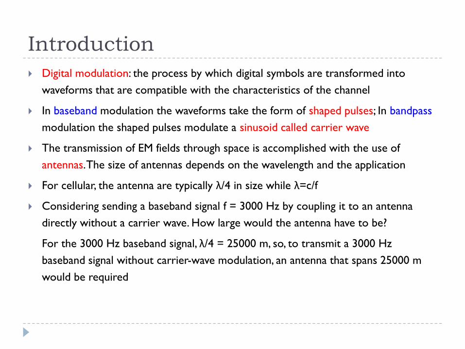
Digital modulation: the process by which digital symbols are transformed into
waveforms that are compatible with the characteristics of the channel
In baseband modulation the waveforms take the form of shaped pulses; In bandpass
modulation the shaped pulses modulate a sinusoid called carrier wave
The transmission of EM fields through space is accomplished with the use of
antennas. The size of antennas depends on the wavelength and the application
For cellular, the antenna are typically λ/4 in size while λ=c/f
Considering sending a baseband signal f = 3000 Hz by coupling it to an antenna
directly without a carrier wave. How large would the antenna have to be?
For the 3000 Hz baseband signal, λ/4 = 25000 m, so, to transmit a 3000 Hz
baseband signal without carrier-wave modulation, an antenna that spans 25000 m
would be required
Bandpass Modulation Techniques
Bandpass modulation (either analog or digital) is the process by which an information signal is converted to a sinusoidal waveform
The sinusoid has three parameters: amplitude, frequency, and phase
Bandpass modulation can be defined as the process whereby the amplitude, frequency, or phase of an RF carrier (or combination of them) is varied in accordance with the information to be transmitted
Digital modulation:
converting the binary PAM signal to sinusoidal signal
the sinusiod of duration T is referred to as a digital symbol
Bandpass Modulation Techniques
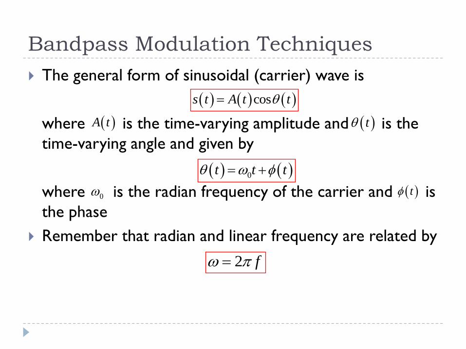
The general form of sinusoidal (carrier) wave is
where is the time-varying amplitude and is the
time-varying angle and given by
where is the radian frequency of the carrier and is
the phase
Remember that radian and linear frequency are related by
coss t A t t
t A t
0t t t
0 t
2 f
Bandpass Modulation Techniques
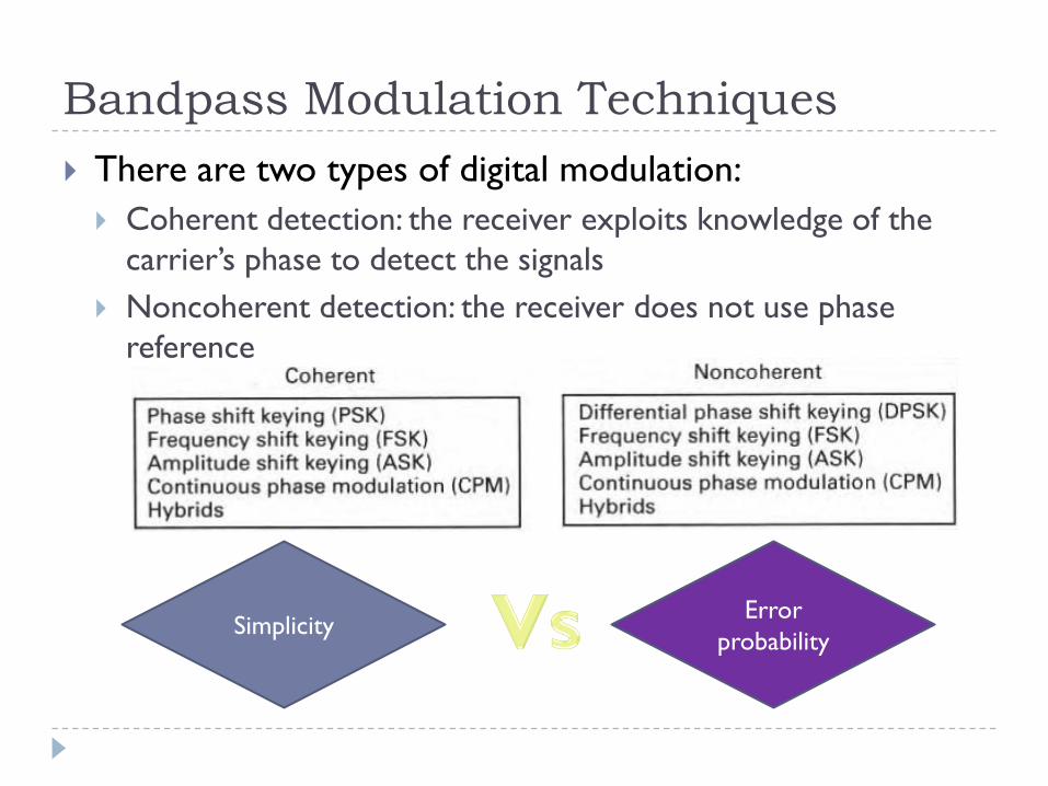
There are two types of digital modulation:
Coherent detection: the receiver exploits knowledge of the
carrier’s phase to detect the signals
Noncoherent detection: the receiver does not use phase
reference
SimplicityError
probability
Phase Shift Keying (PSK)
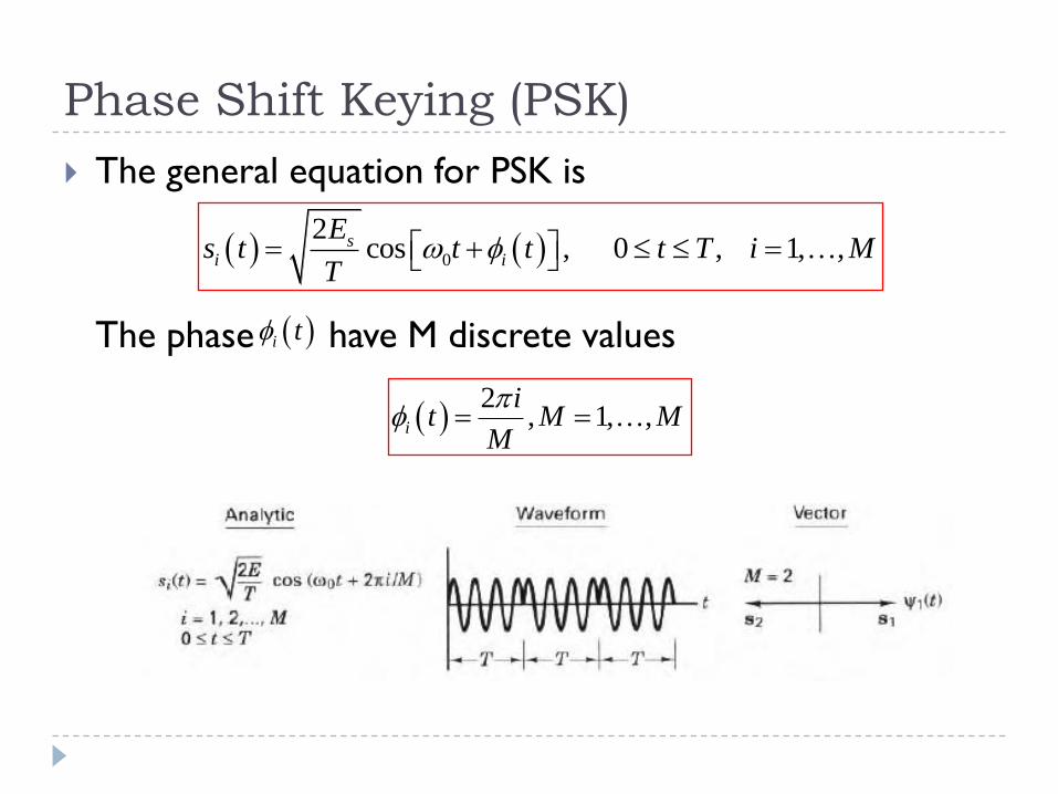
The general equation for PSK is
The phase have M discrete values
0
2cos , 0 , 1, ,s
i i
Es t t t t T i M
T
i t
2
, 1, ,i
it M M
M
Frequency Shift Keying (FSK)
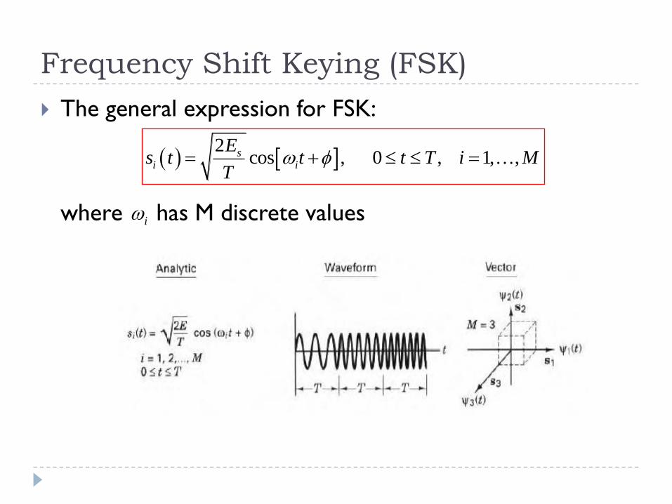
The general expression for FSK:
where has M discrete values
2
cos , 0 , 1, ,si i
Es t t t T i M
T
i
Amplitude Shift Keying (ASK)
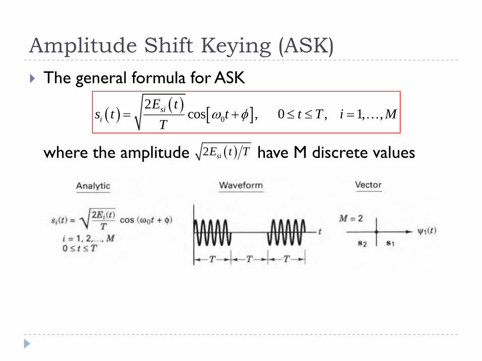
The general formula for ASK
where the amplitude have M discrete values
0
2cos , 0 , 1, ,
si
i
E ts t t t T i M
T
2 siE t T
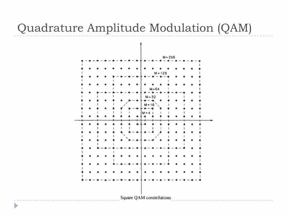
Quadrature Amplitude Modulation (QAM)
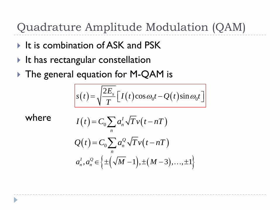
It is combination of ASK and PSK
It has rectangular constellation
The general equation for M-QAM is
where
0 0
2cos sinsE
s t I t t Q t tT
0
I
n
n
I t C a Tv t nT
0
Q
n
n
Q t C a Tv t nT
, 1 , 3 , , 1I Q
n na a M M
Quadrature Amplitude Modulation (QAM)
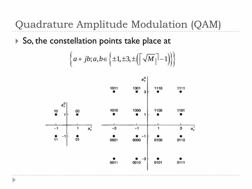
So, the constellation points take place at
; , 1, 3, 1a jb a b M
Quadrature Amplitude Modulation (QAM)
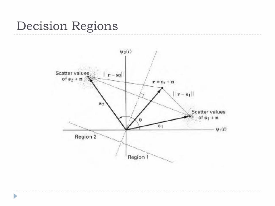
Decision Regions
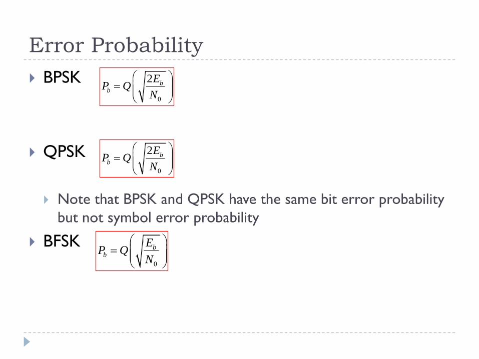
Error Probability
BPSK
QPSK
Note that BPSK and QPSK have the same bit error probability
but not symbol error probability
BFSK
0
2 bb
EP Q
N
0
2 bb
EP Q
N
0
bb
EP Q
N
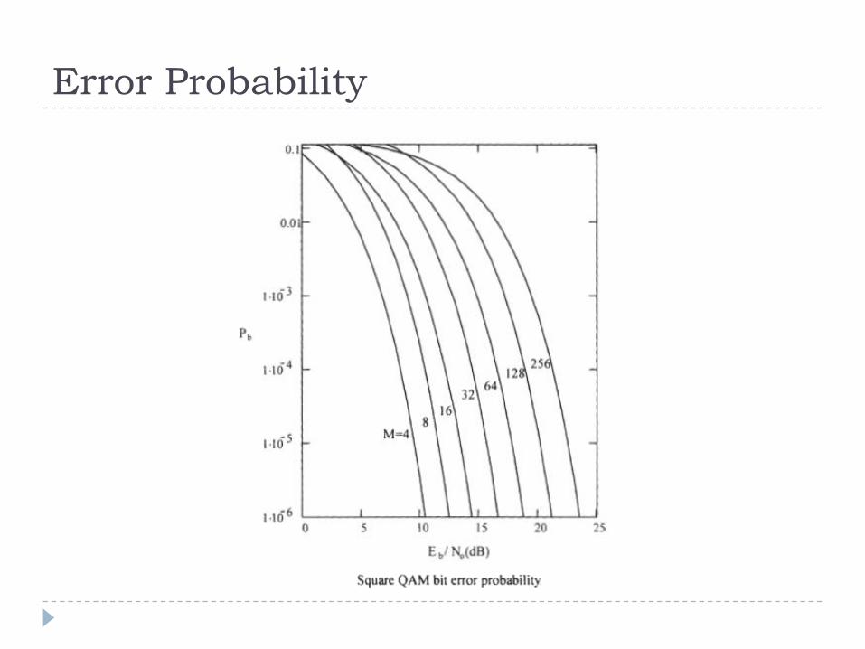
Error Probability
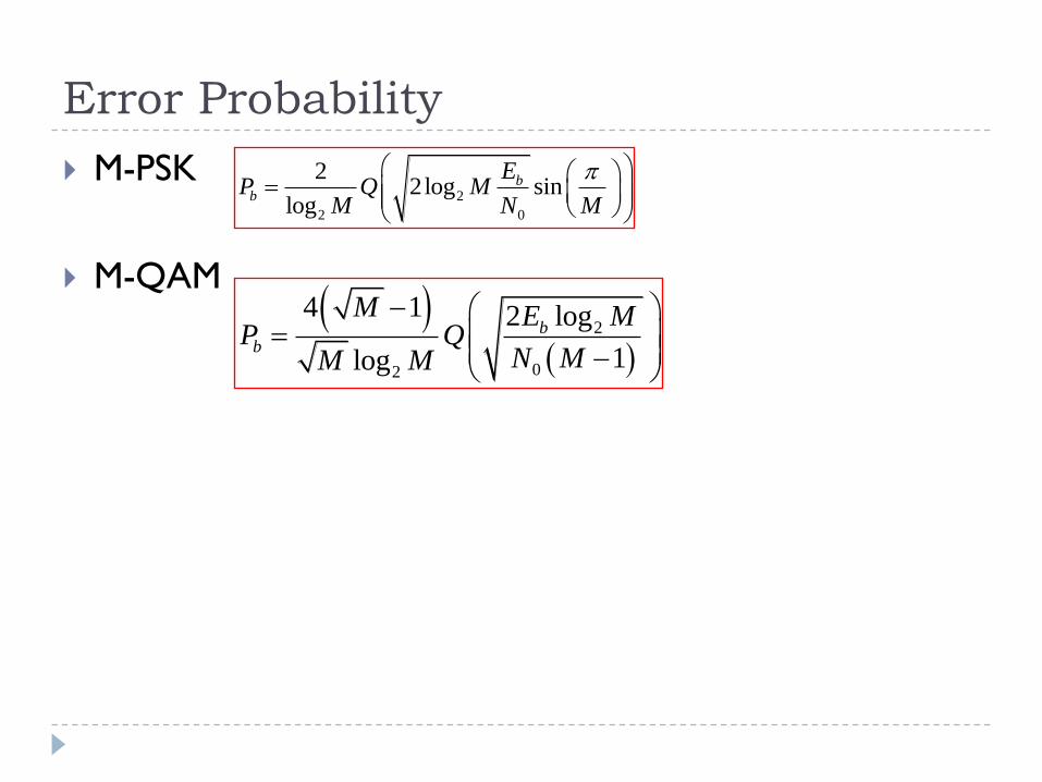
M-PSK
M-QAM
2
2 0
22log sin
log
bb
EP Q M
M N M
2
02
4 1 2 log
1log
bb
M E MP Q
N MM M
Error Probability