The Evolution of Real Property Service Management at PWGSC ...

PWGSC National CADD Standard Computer-Aided Design and Drafting
November 2011 (revised August 2012)


PWGSC – National CADD Standard November 2011 (R1)
TABLE OF CONTENTS
1.0 Introduction 5 1.1 Scope 5
2.0 Project Delivery 6 2.1 Drawing File Format 6
2.2 Project Start-up 6
2.3 Quality Assurance of CADD Data 7
2.4 Work Completed 8
2.5 Production of Contract Drawings 9
2.6 Disclaimers and Limitation of Liabilities 10
2.7 Copyright 10
3.0 PWGSC Computer Aided Drafting Standard 11 3.1 File Presentation 11
3.2 Layering Standard 11
3.3 Block Standard 17
3.4 Text Style Standard 18
3.5 Dimension Style / Multileader Style Standard 19
3.6 Linetype and Hatch Standard 21
3.7 Title Blocks and Graphic Scales 22
3.8 Systems of Measurement and Preferred Scales 23
4.0 Drawing File Naming Conventions 24
Annex A – CADD Layers 25 Architecture 26
Bridges and Dams Engineering 28
Civil Engineering, Site Design and Landscape Architecture 29
Electrical Systems 34
General Information 38
Mechanical 39
Interior Design 42
Legal Surveys 43
Marine 44
Real Property Space Management 46
Structure 48
Annex B – Layer Field Descriptions 49 Group Field 49
Single Layer Field and First Layer Name Extension 50
Second Layer Name Extension 54
Annex C – Pen and Colour Assignment Tables 55
Annex D - Quality Control of CADD Data 60
Annex E – Glossary 63

PWGSC – National CADD Standard November 2011 (R1)
- 5 -
1.0 Introduction Computer-Aided Design and Drafting (CADD) is an integral component of information management for Public Works and Government Services Canada (PWGSC). The production of digital files by CADD is an important corporate asset. The greatest payback for CADD and related technology is in the reuse of the digital data for facilities management and as a foundation for future projects. If CADD files are to be an effective source of information, they must adhere to a standardized set of criteria that all CADD users will understand.
As an ongoing effort to keep up with changing technology, we are pleased to introduce the third edition of the PWGSC National CADD Standard. A concerted effort has been made not only to simplify the standard, but also to reinforce the requirements in areas we feel are critical to our goals.
PWGSC is aware of the emerging technology and processes related to building information modelling (BIM). As BIM represents a significant change, a new BIM standard, by necessity, will be created, facilitating the transition in the architecture, engineering, and construction (AEC) industry.
In addition, some of the regions have developed a regional CADD standard, which is to be used as a complement to this national standard.
For questions or further information regarding this document, please contact the National CADD Coordinator at the following e-mail address:
For a list of regional contacts, please visit the PWGSC National CADD Standard Web site and regional pages at:
http://www.tpsgc-pwgsc.gc.ca/cdao-cadd/index-eng.html
1.1 Scope This standard applies to all services that generate CADD data files for PWGSC, including both internal PWGSC CADD service(s), and external consultant(s).
All CADD data files submitted to PWGSC must meet this standard.

PWGSC – National CADD Standard November 2011 (R1)
- 6 -
2.0 Project Delivery
2.1 Drawing File Format
PWGSC requires all files to be compatible with Microsoft® Operating Systems. The CADD drawing format required for drawings is the AutoCAD® native format DWG file, i.e., they may not be submitted in Adobe® PDF, Autodesk® DWF, or any other simplified format unless specified in the contract. PWGSC will not supply or accept formats that are no longer supported by Autodesk®.
2.2 Project Start-up
All project drawings must be created using the PWGSC National CADD Standard. To ensure this requirement is met, PWGSC will undertake drawing coordination and quality assurance.
Where CADD services will be provided externally, the PWGSC project manager or technical authority will convey its requirements to the consultant or CADD service. PWGSC will provide the pertinent CADD drawings for the related facility or property, the drawing templates, the regional supplement to this standard and the symbol library if applicable. . All new work must meet this standard irrespective of the condition of any existing files provided at the outset of work.
The PWGSC National CADD Standard is available on the PWGSC Web site at http://www.tpsgc-pwgsc.gc.ca/biens-property/cdao-cadd/index-eng.html.
2.2.1 Regional supplement and symbol library
Some of the regions have developed regional supplement and/or a symbol library, which is to be used as a complement to this national standard. The regional supplements are available on the PWGSC Web site at: http://www.tpsgc-pwgsc.gc.ca/cdao-cadd/index-eng.html
2.2.2 CADD Base Plans
The CADD base plans maintained by PWGSC have been drawn from building and property surveys. The intent is to use the files for project drawings, and then PWGSC will be in charge of updating the base plans once the project is completed and measurements of the affected area(s) are verified.
Existing digital information, when available, is used to form the foundation for new project drawings. Any areas critical to the project should be verified by field checking.
New digital drawing files created must be modified to include the most up-to-date information contained in the National CADD Standard. Older legacy CADD data that is used in new drawing files must be updated to the current standard.
The project start-up meeting with the project manager or technical authority and CADD Coordinator should address the extent to which the existing digital files require verification and updating. All new work must meet this standard irrespective of the condition of any existing files provided at the outset of the work.
2.2.3 Template Drawing
Drawing templates set the default metric units, text styles, and dimension styles. Recognizing the differences between engineering drawings and architectural drawings, the templates are provided with dimension styles and lettering for multiple disciplines. PWGSC templates must be used to start a new project. Please visit the PWGSC National CADD Standard Web site or contact the PWGSC project manager regarding the use of drawing templates.

PWGSC – National CADD Standard November 2011 (R1)
- 7 -
2.3 Quality Assurance of CADD Data
PWGSC will carry out quality assurance of delivered CADD data files to ensure adherence with the PWGSC National CADD Standard and regional supplements.
2.3.1 Digital File Review
Colour Assignment
PWGSC colour/line weight assignment must be used. (See 3.2.5 Colour Assignment Standard)
Layer Management
The PWGSC Layering Standard must be used. (See 3.2 Layering Standard)
Standard layer names must be used.
Entities must be on the correct layers.
Text Style Management
Only standard AutoCAD® SHX fonts or TTF fonts can be used. (See 3.4 Text Style Standard)
Dimension Style / Multileader Style Management
The PWGSC naming convention must be used. (See 3.5 Dimension Style MultiLeader Style Standard)
Associative dimensions must be used.
Linetype and Hatch Pattern Management
Only standard AutoCAD® and/or PWGSC linetypes and hatch patterns can be used. (See 3.6 Linetype and Hatch Standard)
Linetype display variables must be used correctly.
External Referencing
The use of external references is authorized only if certain conditions are met. (See 2.3.3 External References (XREF))
PWGSC Title Blocks and Graphic Scales
PWGSC title blocks must be used. Please visit the PWGSC National CADD Standard Web site or contact the PWGSC project manager.
Title blocks must contain the minimum information (See 3.7 Title Blocks and Graphic Scales).
Graphic scales or written scales must accompany all plans, sections, details, and elevations, etc.
1:1 Metric Model
Drawings must be modelled at full size using the International System of Units (S.I.)
Real-World Coordinate System
Maintain coordinate systems integrity for 2D drawings.
2.3.2 Drawing file approval
PWGSC has jurisdiction over all drafting-related aspects of the final drawing, including but not limited to drawing content, title block layout, symbols, and font usage continuity throughout a drawing set. All drawings must be completed to the satisfaction of PWGSC.
In the absence of a drawing submission schedule, PWGSC reserves the right to request CADD data files at the midpoint (50%) of the scheduled work to conduct a CADD drafting review.

PWGSC – National CADD Standard November 2011 (R1)
- 8 -
Note that the content of the digital CADD data file is just as important as the printed content, and no drawing will be accepted as final until all issues are resolved.
Delivered work that fails to meet any requirement in any of these areas will result in the work being deemed unacceptable. The consultant/CADD service will be required to correct the problem(s) at their cost. Furthermore, PWGSC will exercise its option to withhold payment of the contracted work as set out in the contract terms until the work is made right.
Alternatively, PWGSC may, if the consultant/CADD service refuses to correct the problem, make the corrections to the CADD data files and printed drawing plans and deduct the cost thereof from the consultant’s/CADD service’s fee. The consultant/CADD service grants to PWGSC an irrevocable licence to make such corrections and use the corrected CADD data files and printed drawing plans as it sees fit. Furthermore, PWGSC reserves the right to use the printed drawing plans resulting from the CADD data files with no payment obligation until the CADD data files are corrected.
2.3.3 External References (XREF)
The use of external references will be conditionally authorized if the regional supplement of the CADD standard where the work is being performed permits the use of xrefs.
When this condition is met, xrefs may only be used in conjunction with the “Sheet Set Manager” to support the transmission of drawing files in a compressed format.
In all the other cases, external references must be converted into blocks. (Do not BIND XREFs, instead use BIND INSERT.) Under no circumstances should a drawing contain referenced symbols; they must be
inserted as blocks.
2.3.4 Raster Images
When separate raster images are included in a drawing, all related files containing images and information on coordinates, rotation angles, scaling, etc. are to be provided. As these files are essential for their geo-referencing, they must be delivered intact. Raster images should be used as a reference only and cannot replace the vector data normally required in drawing files.
2.3.5 Digital Signature
Drawing files containing digital signatures are not accepted and can not legally replace printed copies signed and stamped as original.
2.4 Work Completed
When work is complete and the drawing files are delivered to PWGSC, they must be reviewed for compliance with the National CADD Standard. The CADD service shall maintain the drawings in a suitable manner until all drawings for the project are verified and accepted by PWGSC. Once completed, a PWGSC will archive the file(s) in an electronic document and record management system.
PWGSC – National CADD Standard November 2011 (R1)
- 9 -
2.4.1 File Delivery
File transfer will be stipulated by PWGSC on a per project basis by one of the methods listed below:
Submission and upload of drawing files to a project collaboration tool (PCT) designated by the contact person.
Submission and upload of drawing files to an information management tool designated by the contact person.
Submission and transfer of drawing files through e-mail.
Should a file transfer exceed the e-mail file transfer limit, the file can be uploaded to an FTP site if permitted under regional rules.
In the case of inability to access a FTP site, lack of Internet access, no permission, or security considerations of the drawing content (unencrypted Protected B, Protected C, Confidential, Secret, Top Secret), a portable electronic storage media (CD, DVD, USB key, etc.) will be delivered to the designated contact person.
Note: The FTP sites are not secure. Therefore, files containing sensitive information (requiring security clearance greater than Protected A) cannot be uploaded to this site and must be transferred via a portable electronic storage media.
After uploading the file, e-mail the following information to the designated contact person:
Project location
Project name
Project number
Fully qualified URL path/file name(s) link
Notes:
Uploaded files must be named using only alphanumeric characters with no spaces.
All files are deleted from the site every second day. Timely notification is required to ensure file retrieval.
No files are to be presented as an executable (.exe extension).
Files should not be password-protected
Files should not contain any electronic signature.
Drawings should not contain hyperlinks.
2.5 Production of Contract Drawings
The following formats should be applied.
2.5.1 Sheet Size for Page Setup
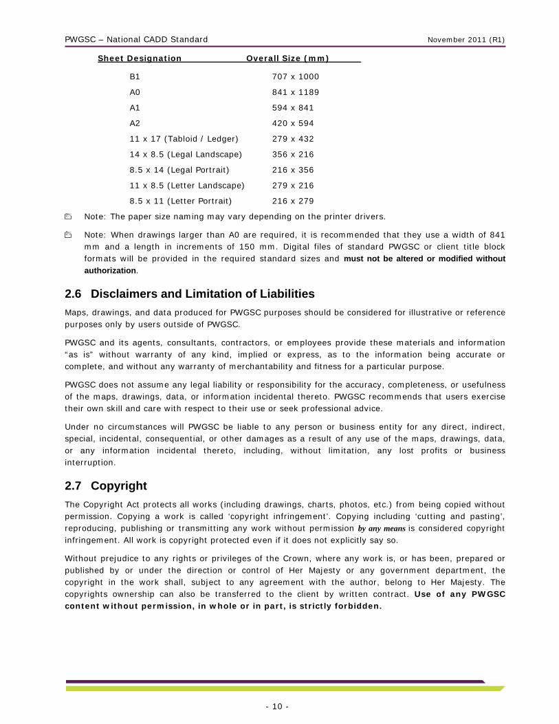
This table shows the sheet designations and sizes for the drawing page setup. Drawing sheet size will conform to the following specifications:
PWGSC – National CADD Standard November 2011 (R1)
- 10 -
Sheet Designation Overall Size (mm)
B1 707 x 1000
A0 841 x 1189
A1 594 x 841
A2 420 x 594
11 x 17 (Tabloid / Ledger) 279 x 432
14 x 8.5 (Legal Landscape) 356 x 216
8.5 x 14 (Legal Portrait) 216 x 356
11 x 8.5 (Letter Landscape) 279 x 216
8.5 x 11 (Letter Portrait) 216 x 279
Note: The paper size naming may vary depending on the printer drivers.
Note: When drawings larger than A0 are required, it is recommended that they use a width of 841 mm and a length in increments of 150 mm. Digital files of standard PWGSC or client title block formats will be provided in the required standard sizes and must not be altered or modified without
authorization.
2.6 Disclaimers and Limitation of Liabilities
Maps, drawings, and data produced for PWGSC purposes should be considered for illustrative or reference purposes only by users outside of PWGSC.
PWGSC and its agents, consultants, contractors, or employees provide these materials and information “as is” without warranty of any kind, implied or express, as to the information being accurate or complete, and without any warranty of merchantability and fitness for a particular purpose.
PWGSC does not assume any legal liability or responsibility for the accuracy, completeness, or usefulness of the maps, drawings, data, or information incidental thereto. PWGSC recommends that users exercise their own skill and care with respect to their use or seek professional advice.
Under no circumstances will PWGSC be liable to any person or business entity for any direct, indirect, special, incidental, consequential, or other damages as a result of any use of the maps, drawings, data, or any information incidental thereto, including, without limitation, any lost profits or business interruption.
2.7 Copyright
The Copyright Act protects all works (including drawings, charts, photos, etc.) from being copied without permission. Copying a work is called ‘copyright infringement’. Copying including ‘cutting and pasting’, reproducing, publishing or transmitting any work without permission by any means is considered copyright infringement. All work is copyright protected even if it does not explicitly say so.
Without prejudice to any rights or privileges of the Crown, where any work is, or has been, prepared or published by or under the direction or control of Her Majesty or any government department, the copyright in the work shall, subject to any agreement with the author, belong to Her Majesty. The copyrights ownership can also be transferred to the client by written contract. Use of any PWGSC content without permission, in whole or in part, is strictly forbidden.
PWGSC – National CADD Standard November 2011 (R1)
- 11 -
3.0 PWGSC Computer Aided Drafting Standard This section describes the general PWGSC Computer Aided Drafting Standard. Specific instructions can be added in the context of a request for proposal.
3.1 File Presentation
Files presented must conform to the following rules:
A drawing must be purged of all definitions that are not used, such as layer names, text styles, dimension styles, layer filters, and blocks.
A drawing must not contain any object definitions without geometry, such as empty text or blocks without objects.
No objects should reside on layer “0” or “DEFPOINTS” except for objects contained in a block definition and dimensions. Use the “Plot/Non plot” layer property instead of the Defpoints layer.
A drawing must not contain errors that are detectable using the Audit command.
Drawings are to be modelled at full scale (real-world units) in model space, with text, symbols, hatch patterns, and line widths adjusted by the required scale factor.
All presented files must also adhere to the following rules of best practice:
When appropriate to the type of drawing, lines must be drawn in an orthogonal mode.
All vector endpoint intersections must be drawn with closed corners.
The drawing must be saved with properly formatted Page Setup (Paper Size, Plot Style, Plot Area, Plot Scale, etc.). The main layout must be active and all the viewports adjusted and locked to the correct scale.
3.2 Layering Standard
All digital CADD files must follow the PWGSC Layering Standard. The standard facilitates data management by using a layering structure and naming convention to organize the drawing data in the CADD files into related data groups.
See Annex A – CADD Layers for the complete Standard Layer List.
See Annex B – Layer Field Descriptions for the abbreviations and descriptions lists used to create layer names.
3.2.1 Sorting Graphic Data into Related Data Groups
Layers are used to sort the graphical data types depicted by the line work into related data groups. (They are not intended for use in sorting line weights, line types, colours, or other schemes.)
Layering is the only way to identify what the entities on a graphical screen represent without resorting to annotations. For example, it answers questions such as whether a rectangle represents a building outline, a concrete pad, a storage tank, or whether it is an annotation box. All digital CADD files must follow the PWGSC Layering Standard to create the appropriate layers to accommodate the grouping of related data.
To simplify the layering, drawing data can be broken into two major groupings: principal data and supporting data. The level of complexity and number of layers required for the two groups are significantly different.
PWGSC – National CADD Standard November 2011 (R1)
- 12 -
3.2.2 Principal Data
Principal data is contained mainly in the plan views of the facility, i.e., the base plan, floor plan, site plan, etc.
This type of data requires strict adherence to layer naming and proper grouping of data. The line work used to depict facility components must always be drawn using the most up-to-date and accurate information available. Line work depicting objects must be placed in the proper standard layer according to the data type being represented. For example, in a floor plan, the walls, doors, windows, and bathroom fixtures must be grouped under separate layers.
3.2.3 Supporting Data
Supporting data is made up of sections, details, elevations, schedules, legends, and title blocks, etc.
This type of data requires minimal layering breakdown. Line work in a detail representing different components does not need to be placed in separate layers. For example, a building construction detail can be drawn with foundation wall, frame wall, floor, and roof line work in a single layer, although the dimensions, annotation, and hatching should be separated.
3.2.4 Layering Naming Convention
Layering of CADD information must adhere to the layering naming convention described in this section.
The layer is the basic tool for organizing and managing graphic information. Layers are used to sort graphic objects into groupings of related data. PWGSC has developed a modular, alphanumeric layer nomenclature format designed to sort graphic data in a specific manner.
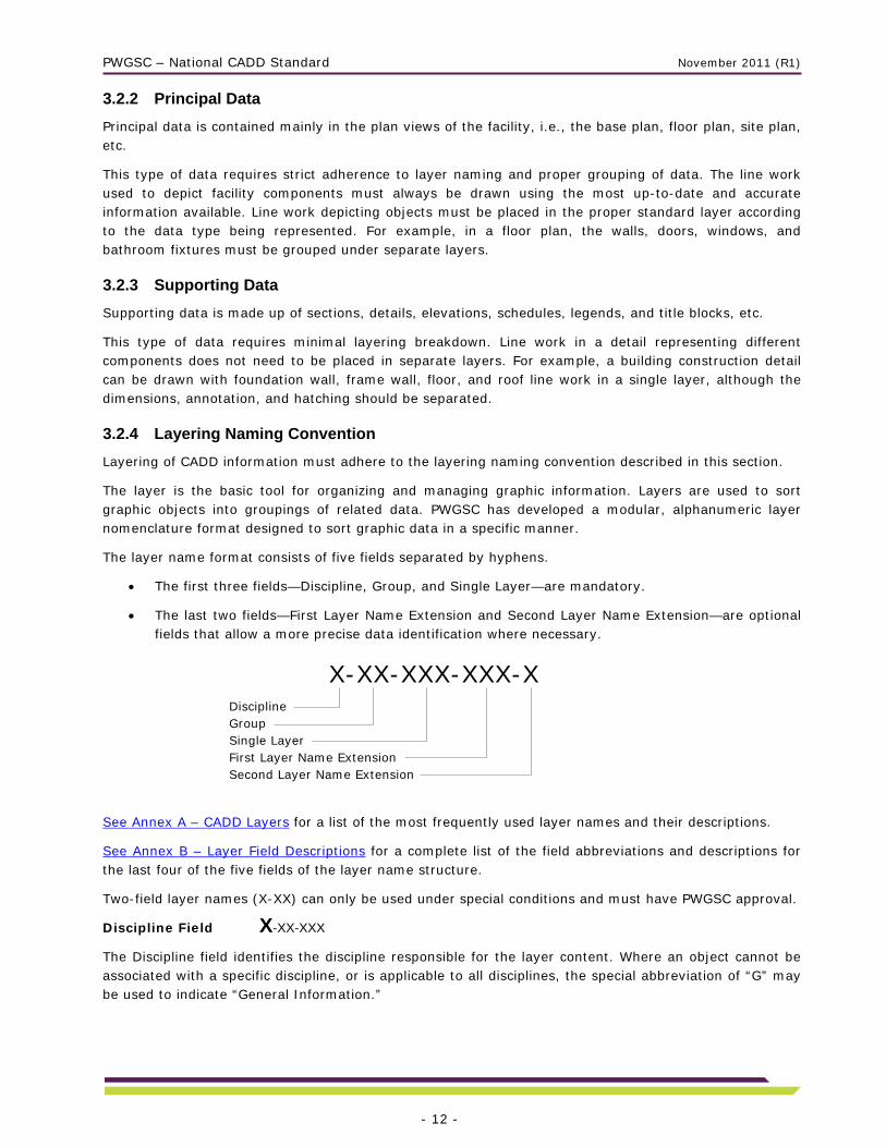
The layer name format consists of five fields separated by hyphens.
The first three fields—Discipline, Group, and Single Layer—are mandatory.
The last two fields—First Layer Name Extension and Second Layer Name Extension—are optional fields that allow a more precise data identification where necessary.
See Annex A – CADD Layers for a list of the most frequently used layer names and their descriptions.
See Annex B – Layer Field Descriptions for a complete list of the field abbreviations and descriptions for the last four of the five fields of the layer name structure.
Two-field layer names (X-XX) can only be used under special conditions and must have PWGSC approval.
Discipline Field X-XX-XXX
The Discipline field identifies the discipline responsible for the layer content. Where an object cannot be associated with a specific discipline, or is applicable to all disciplines, the special abbreviation of “G” may be used to indicate “General Information.”
X-XX-XXX-XXX-XDisciplineGroupSingle LayerFirst Layer Name ExtensionSecond Layer Name Extension

PWGSC – National CADD Standard November 2011 (R1)
- 13 -
Discipline Field Abbreviations List:
A Architecture
B Bridges and Dams Engineering
C Civil Engineering, Site Design, and Landscape Architecture
E Electrical Systems
G General Information
H Mechanical
I Interior Design
L Legal Surveys
M Marine
R Real Property Space Management
S Building Structure
Group Field X-XX-XXX
The Group field identifies groupings of common types of drawing information relevant to each discipline. The Group abbreviations defined for each discipline are listed in the Standard Layer List in Annex A – CADD Layers. In addition, there are some common Group abbreviations defined for use with all disciplines for supporting graphic data such as sections, details, and others. Annex B – Layer Field Descriptions contains a complete list of all Group abbreviations and their descriptions.
Examples of common Group field abbreviations:
GL Global
GR Grid
PL Plan
SC Schedules
Single Layer Field X-XX-XXX
The Single Layer field subdivides the classifications to identify each layer more precisely. Single Layer abbreviations allow information pertaining to Physical Properties, Materials, Graphics, Text and discipline related data such as building systems to be included. The Single Layer abbreviations are listed in the Standard Layer List in Annex A – CADD Layers and Annex B – Layer Field Descriptions.
First Layer Name Extension (Optional) X-XX-XXX-XXX-X
The First Layer Name Extension, like the Single Layer field, allows information pertaining to Physical Properties, Materials, Graphics, Text and discipline related data to be included. The extensions use the same abbreviations as the Single Layer field. They may be used with any valid layer from the Standard Layer List. They may also be used as a Single Layer field value where appropriate.
Examples of common Single Layer and First Layer Name Extension abbreviations for all disciplines: (See Annex B - Layer Field Descriptions for a complete list.)

PWGSC – National CADD Standard November 2011 (R1)
- 14 -
Physical Properties:
ABV Above ground, above grade
EME Emergency
EQP Equipment
EXT Exterior
HOR Horizontal
INT Interior
NOD Node, horizontal reference point
OPN Openings
RET Return
SUP Supply
UND Underground, below grade
VER Vertical
Materials:
ASP Asphalt
BLK Block
BRK Brick
CON Concrete
CRP Carpet
FIN Finishes
GRV Gravel
INS Insulation
PLA Plastic
STL Steel
STO Stone
TIL Tile
TIM Timber
Graphics:
3DM 3D model components of 2D symbols
CLR Colours
DIG Digitized or vectorized from scanned image
HAT Hatching
LIN Line work
OLN Outlines
PRO Profiles
SPC Special
SYM SymbolsTAB Tables
TMP Temporary
Texts:
ATT Attributes
DIM Dimensions
IDN Identification numbers or names
SPT Spot elevations
TXT Annotation, Text, detail notations, bubbles, graphic scales

PWGSC – National CADD Standard November 2011 (R1)
- 15 -
Second Layer Name Extension (Optional) X-XX-XXX-XXX-X
The Second Layer Name Extension allows information pertaining to Geometry, Construction, Status, Second Language, and Numerical Options to be included. The extensions may be used with any valid layer from the Standard Layer List. Annex B – Layer Field Descriptions contains a complete list of all Second Layer Name Extension abbreviations and their descriptions.
Valid Layer Name Formats:
Four variants of the layer name format will be accepted, as indicated below:
Required:
Discipline Field Architecture
Group Field Walls
Single Layer Field Exterior
A-WL-EXT Optional:
A-WL-EXT-BRK First Layer Name Extension Brick
A-WL-EXT-E Second Layer Name Extension Existing
A-WL-EXT-BRK-E Second Layer Name Extension Existing
Free Text Examples:
Add an underscore character at the end of a valid layer name to append free text to the layer name.
M-SN-SPT_-1.0 Soundings at -1.0 m depth
M-SN-HWL_14 January 1990 High Water Line on a specific date
Existing Floor Plan Examples:
Where plans are specifically titled “New” (or “Existing), the “N” (or “E”) Second Layer Name Extension modifier indicating the construction status may be omitted, but all disparate construction status extensions must be included.
A-WL-INT-N Architecture - Wall - Interior - New
A-WL-INT-X Architecture - Wall - Interior - Remove
A-WL-OLN Architecture - Wall Outline - Exterior (“Existing” implied)
A-DR-INT Architecture - Door - Interior (“Existing” implied)
A-DR-INT-N Architecture - Door - Interior - New
A-WD-EXT Architecture - Window - Exterior (“Existing” implied)
Symbols Examples:
When a symbol is placed to represent an object, it must be placed in a symbols layer.
E-SD-SYM Electrical - Site Distribution - Symbols (Power poles, luminary, etc.)
G-GL-SYM General - Global - Symbols (Key plans, north arrow, bar scale, etc.)

PWGSC – National CADD Standard November 2011 (R1)
- 16 -
Detail Examples:
Supporting data such as dimensions, annotation, and hatching should be separated as indicated in the examples below. Colour should be set “Bylayer” for the majority of the entities in a layer and specifically where necessary to obtain varying line weights in that layer.
G-DT-LIN General - Detail - Line work (Wall, floor and roof line work)
G-DT-TXT General - Detail - Text (Annotations, title, graphic scale, etc.)
G-DT-DIM General - Detail - Dimensions
G-DT-HAT General - Detail - Hatching (Insulation, wood grain, etc.)
Schedule Examples:
A-SC-LIN Architecture - Schedule - Line work (Schedule grid or Line work)
A-SC-TXT Architecture - Schedule - Text (Schedule data, annotation)
Plan Views Examples:
Supporting data can also appear on plan views.
H-PL-TXT Mechanical - Plan - Text (Titles, graphic scale, annotation bubbles)
S-PL-DIM Structural - Plan -Dimensions
3.2.5 Colour Assignment Standard: Layer Colours and Pen Weights
Colour is to be used as a method of defining line weight to the plotter. Layers must be assigned appropriate colours and entities should be created with colour “Bylayer” where possible, except as provided for in the creation of symbols. If a CTB is provided by PWGSC, it must be used.
Suggested Line Weight Settings:
Extra Thin - 0.10 mm
Hatching
Thin - 0.15 to 0.25 mm
Dimension Lines Centre Line Intermediate Contour Lines
Leader and Extension Phantom Lines Grid Lines
Medium - 0.30 mm to 0.50 mm
Hidden Lines Index Contour Line Text Normal (0.3 mm)
Text - Sub Headings (0.5 mm) Visible Object Outlines
Thick - 0.70 mm
Cutting Lines Match Lines Reference Lines
Section Lines Text - Titles/Major Headings Viewing Planes
Extra Thick - 1.00 mm
Title Sheet Border

PWGSC – National CADD Standard November 2011 (R1)
- 17 -
3.2.6 Provision for Creation of New Layers
Because the Standard Layer List (Annex A – CADD Layers) does not cover all possibilities, the layering standard provides for the ability to create new layer names for new objects as required.
As in the preceding example of E-SD-SYM, a quick look in the Standard Layer List under the Electrical Systems section would indicate that this layer name is invalid since it is not on the list. However, it is an acceptable layer name created by adding an existing First Layer Name Extension to an existing Discipline-Group abbreviation.
The rules for creating new layer names are as follows:
a) A proper standard layer name for the object must not already exist.
b) Must follow the standard layer name format.
c) Must use an existing Discipline abbreviation. (E-SD-SYM)
d) Must use an existing Group abbreviation. (E-SD-SYM)
e) Must use an existing three-character Single Layer field abbreviation or First Layer Name Extension. (E-SD-SYM)
3.3 Block Standard
AutoCAD® blocks are used to group entities. Graphic blocks shall not be exploded. Blocks representing simple objects or simple symbols shall not contain nested blocks (blocks made of blocks). The use of groups is preferable when grouping blocks together, for example, a table with chairs around it. Most symbols should be created with linetype and colour “Byblock.” This allows complete control over the appearance of the symbol. By default a symbol will take on the properties of the layer it is placed on, but it can be changed to suit requirements independent of the layer settings.
There are two different ways of creating and inserting AutoCAD® blocks, depending on their complexity. The basic rules are as follows:
1. Simple blocks with one data type, e.g., toilet fixtures, furniture:
a) Create the block on layer “0.”
b) The block must be inserted on the proper layer, e.g., office chair inserted on layer I-FU-SET.
2. Complex graphics requiring the use of multiple data types:
a) Create each data type on its proper layer.
b) Colour and linetype must be “Bylayer” or “Byblock” so that these two attributes may be assigned to the symbol regardless of the layer properties the symbol is inserted on, e.g., title blocks created with objects on different layers.
Objects that could be represented by AutoCAD® blocks are categorized as being either symbols or graphics.
3.3.1 Graphics
Graphics are AutoCAD® blocks that are dimensionally accurate pictorial representations of real objects. A
graphic may be a simplified representation of a building component or assembly such as a desk or chair,
but it is accurate with respect to the component’s principal dimensions.
Drawing scale does not affect the insertion of graphics. Graphics may be fixed or variable, and basic rules
for their creation and insertion must be followed:
PWGSC – National CADD Standard November 2011 (R1)
- 18 -
1. Fixed - Not scaled
a) Objects must be created full size.
b) Graphics must be inserted with 1-by-1 scale in model space.
2. Variable - Scaled to represent different size objects such as doors, round tables, etc.
a) Objects must be created inside a 1-by-1 square
b) Blocks must be inserted using the actual dimensions of the objects they represent in model
space.
3.3.2 Symbol (Annotative)
Symbols are AutoCAD® blocks that are pictorial representations of objects not drawn to scale, such as an electrical outlet symbol. Drawing scale affects symbols in the same manner as annotation and therefore must be inserted into a working drawing at a scale factor corresponding to the drawing or plot scale as required.
Note: It is now possible to create annotative blocks that can scale themselves automatically to any given scale. To avoid confusion, it is strongly recommended to use only one method throughout each project drawing set: the traditional method that lets the user choose the insertion scale, or the Annotative option that automatically manages the insertion scale.
Basic rules for the creation of symbols must be followed:
a) Symbols should be drawn at actual plotted size and not smaller than 2.5 mm. The Annotative option can also be selected when creating the block.
b) Symbols should be inserted using the plotted scale if they are inserted in model space, and 1 if they are inserted in paper space (layout), i.e., 50x on a 1:50 floor plan in model space, or 1x on a 1:1 drawing sheet in paper space. If the block was created with the annotative option selected, it will scale itself automatically during the insertion.
3.3.3 Block Library
Taking into account the specific needs of each project and the huge diversity, there is no national block library.
a) If a block library is provided with a project, the consultant/CADD service must use it.
b) All the blocks should be created respecting the rules described in this block standard.
c) Use of blocks should be uniform throughout each project drawing set.
d) If no blocks are provided, the consultant/CADD service must have their block library pre-approved by PWGSC.
3.3.4 Block Naming
A good structure for block naming is very important to allow for the creation and management of schedules, inventories, legends, etc. If the consultant/CADD service uses their own block library, they need to use a pertinent naming convention that must be pre-approved by the lead technologist.
3.4 Text Style Standard
Text styles for use in drawings must be created using Standard AutoCAD® SHX, the following TTF font files: Arial, Arial Narrow, and StylusBT and any font files specifically provided by PWGSC.
Annotative text styles are allowed.
PWGSC – National CADD Standard November 2011 (R1)
- 19 -
Text style usage should be uniform throughout each project drawing set and limited to a maximum of four different font files per project that will be determined in collaboration with PWGSC.
The height of text styles must be set to 0 (not fixed) so that it can be changed to suit different scaling requirements.
All French characters should be accented whether upper or lower case.
Private company logos must not contain a special font file.
Paragraphs must be created with MTEXT objects.
Note: It is now possible to create annotative text styles that can size themselves automatically to any given scale. To avoid confusion, it is strongly recommended to use only one method throughout each project drawing set: traditional text styles or annotative text styles.
3.4.1 Text Style Naming
Text style names should reflect the information below:
Usage
Font name
Any other special effects (if required)
Examples:
NOTES_SIMPLEX Text style with SIMPLEX used for notes
TITLE_ARIAL_WF-1.2 Text style with ARIAL and width factor 1.2 used for titles
SPECIAL_SIMPLEX_OA-20 Text style with SIMPLEX, oblique angle 20 used for special notes
NOTES_ARIAL_ANNO Text style with ARIAL and Annotative property enabled for notes
3.4.2 Text height
Standard text height for:
Notes, dimensions, annotations, etc. 2.5 mm
Major headings 4.5 mm, 5.0 mm
Subheadings 3.5 mm.
Text smaller than 2.5 mm can only be used under special conditions and must have PWGSC approval.
3.5 Dimension Style / Multileader Style Standard
All dimensioning must be created on entities in model space with associative dimensions.
Annotative dimension styles and Multileader Styles are now allowed. However, as for blocks and text styles, it is strongly recommended to use only one method throughout each drawing set: traditional dimension styles set with different overall scales to suit different printing scales, or annotative dimension styles that are set up automatically based on the drawing scale.
Two formats are used to cover most applications for PWGSC projects:
a) Engineering with arrowheads for dimension and leader terminators
b) Architectural with ticks for dimension terminators and arrowheads for leader terminators.
PWGSC – National CADD Standard November 2011 (R1)
- 20 -
3.5.1 Dimension Style Naming
Dimension style usage should be uniform throughout each project drawing set. Using dimension styles reduces the time necessary to create, edit, and maintain dimensions. Dimension styles are created by specifying values for a number of dimension variables and saving the style with a unique name. The dimension style controls the appearance of all the dimensions created while the dimension style is active. Changes to the dimension style will automatically be reflected in the associated dimensions.
Use of Dimension Style Overrides is not allowed and the dimensions must be associative. A new dimension style should be created to work with different properties.
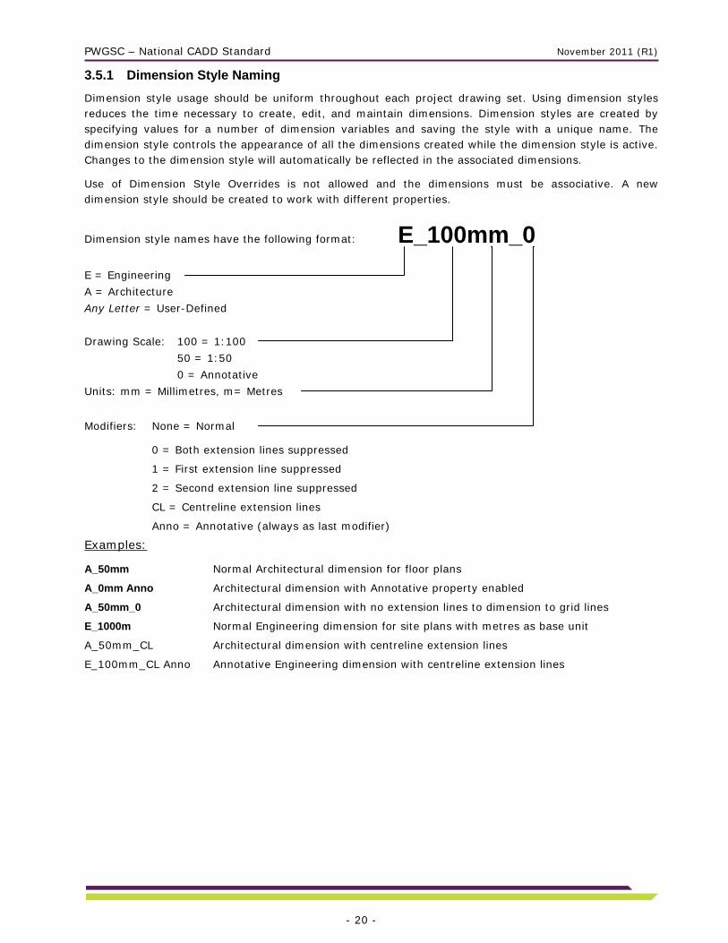
Dimension style names have the following format: E_100mm_0
E = Engineering
A = Architecture
Any Letter = User-Defined
Drawing Scale: 100 = 1:100
50 = 1:50
0 = Annotative
Units: mm = Millimetres, m= Metres
Modifiers: None = Normal
0 = Both extension lines suppressed
1 = First extension line suppressed
2 = Second extension line suppressed
CL = Centreline extension lines
Anno = Annotative (always as last modifier)
Examples:
A_50mm Normal Architectural dimension for floor plans
A_0mm Anno Architectural dimension with Annotative property enabled
A_50mm_0 Architectural dimension with no extension lines to dimension to grid lines
E_1000m Normal Engineering dimension for site plans with metres as base unit
A_50mm_CL Architectural dimension with centreline extension lines
E_100mm_CL Anno Annotative Engineering dimension with centreline extension lines
PWGSC – National CADD Standard November 2011 (R1)
- 21 -
3.5.2 Multileader Style Naming
Multileader style usage should be uniform throughout each project drawing set.
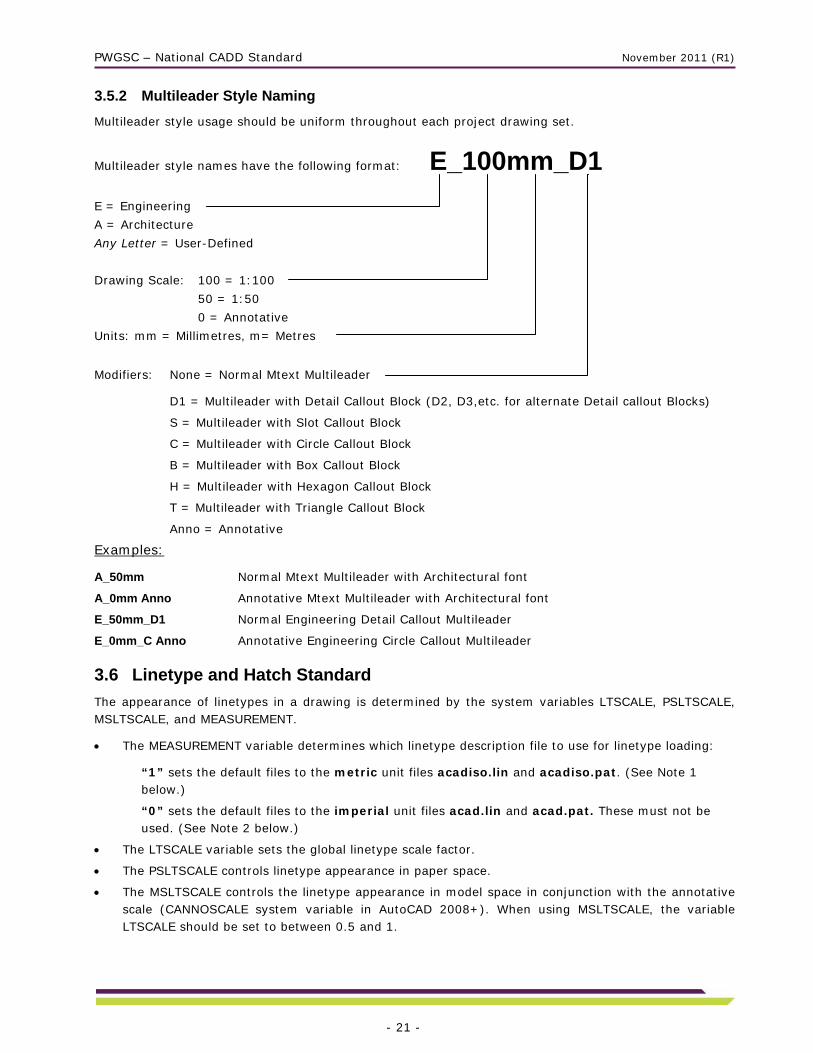
Multileader style names have the following format: E_100mm_D1
E = Engineering
A = Architecture
Any Letter = User-Defined
Drawing Scale: 100 = 1:100
50 = 1:50
0 = Annotative
Units: mm = Millimetres, m= Metres
Modifiers: None = Normal Mtext Multileader
D1 = Multileader with Detail Callout Block (D2, D3,etc. for alternate Detail callout Blocks)
S = Multileader with Slot Callout Block
C = Multileader with Circle Callout Block
B = Multileader with Box Callout Block
H = Multileader with Hexagon Callout Block
T = Multileader with Triangle Callout Block
Anno = Annotative
Examples:
A_50mm Normal Mtext Multileader with Architectural font
A_0mm Anno Annotative Mtext Multileader with Architectural font
E_50mm_D1 Normal Engineering Detail Callout Multileader
E_0mm_C Anno Annotative Engineering Circle Callout Multileader
3.6 Linetype and Hatch Standard
The appearance of linetypes in a drawing is determined by the system variables LTSCALE, PSLTSCALE, MSLTSCALE, and MEASUREMENT.
The MEASUREMENT variable determines which linetype description file to use for linetype loading:
“1” sets the default files to the metric unit files acadiso.lin and acadiso.pat. (See Note 1 below.)
“0” sets the default files to the imperial unit files acad.lin and acad.pat. These must not be used. (See Note 2 below.)
The LTSCALE variable sets the global linetype scale factor.
The PSLTSCALE controls linetype appearance in paper space.
The MSLTSCALE controls the linetype appearance in model space in conjunction with the annotative scale (CANNOSCALE system variable in AutoCAD 2008+). When using MSLTSCALE, the variable LTSCALE should be set to between 0.5 and 1.

PWGSC – National CADD Standard November 2011 (R1)
- 22 -
Note 1: Drawings must not contain linetypes, complex linetypes or hatch patterns other than those respectively defined in the acadiso.lin and acadiso.pat files supplied with the AutoCAD® based Autodesk products or other linetypes supplied by PWGSC.
Note 2: The linetypes and hatch patterns contained respectively in the acad.lin and acad.pat files should not be used because they are drawn to be used with imperial drawings. For consistent linetype appearance and plotting results, the required values for the variables are as follows:
1. Final Drawings: Title sheet must be in paper space with multiple, variously scaled VIEWPORTS.
a) MEASUREMENT = 1
b) LTSCALE between 0.5 and 1.0 (See Note 3 below.)
c) PSLTSCALE = 1 (On)
Note 3: The LTSCALE value should be set between 0.5 and 1.0 while printing in paper space depending on the size of the linetypes used in the drawing.
Do not set the linetype scale at the entity level. The Current Object Scale in the Linetype Properties dialog box (system variable CELTSCALE) must be set to 1.0 to ensure that the creation of new entities do not have entity-level linetype scaling.
For consistent hatch pattern plotting and scanning results, gray scale SOLID hatch patterns are not permitted on contract drawings.
3.7 Title Blocks and Graphic Scales
3.7.1 Title Block Set-up
Completed drawings must adhere to the following composition standard:
a) Title block sheets must always be inserted in a layout (paper space) at 0,0,0 with scale factor of 1 and rotation angle of 0.
b) Model space graphics must appear in the layout in correctly scaled VIEWPORTS.
c) There must be only one (1) title block per layout.
d) The title block is not to be exploded. Attributes must be used to enter title block information.
e) No entities outside the title block perimeter.
3.7.2 Information in Title Blocks
All project drawings must be compiled on standard sheets and must be in accordance with the PWGSC corporate identity. The lead technologist for each project will coordinate the size of the sheet to be used and provide a standard title block and the content of the title block fields.
Each title block must contain the information below:
a) Project name
b) Address
c) Drawing name, e.g. floor plan, building
d) Measured or designed by and date
e) Drawn by and date
f) Approved by and date
g) Project manager
h) PWGSC project number
i) Tender
j) Drawing number

PWGSC – National CADD Standard November 2011 (R1)
- 23 -
k) Revision chart
l) Consultant or CADD service identification
m) North arrow
n) Site plan (if pertinent)
3.7.3 Headings, Titles, and Graphic Scales
To facilitate scaling from reduced or enlarged reproductions, each plan, section, detail, elevation, profile, etc. on a completed drawing sheet shall be accompanied by a graphic scale. The graphic scale shall be located immediately below the pertinent heading on final plot.
3.8 Systems of Measurement and Preferred Scales
The International System of Units (S.I.) must be used to prepare all drawings.
The unit for linear dimensioning is the millimetre, except where the scope of the drawing requires the use of the metre, such as in site plans.
Integers shall indicate millimetres, e.g. 435, 4300. Decimal numbers with three decimal places shall indicate metres, e.g. 5.435, 4.300.
All other dimensions and notations should be followed by the unit symbol.
Preferred Viewport Scale:
1:1 1:25 1:500
1:2 1:50 1:1000
1:5 1:100 1:2000
1:10 1:200 1:5000
1:20 1:250 1:10000
PWGSC – National CADD Standard November 2011 (R1)
- 24 -
4.0 Drawing File Naming Conventions All CADD information submitted must be arranged in a logical format so that it can be easily accessed and modified by the user. This standard provides a framework for the information and will assist in data entry, manipulation, storage, and retrieval at different stages of the design and operation of the facility over its life cycle.

PWGSC – National CADD Standard November 2011 (R1)
- 25 -
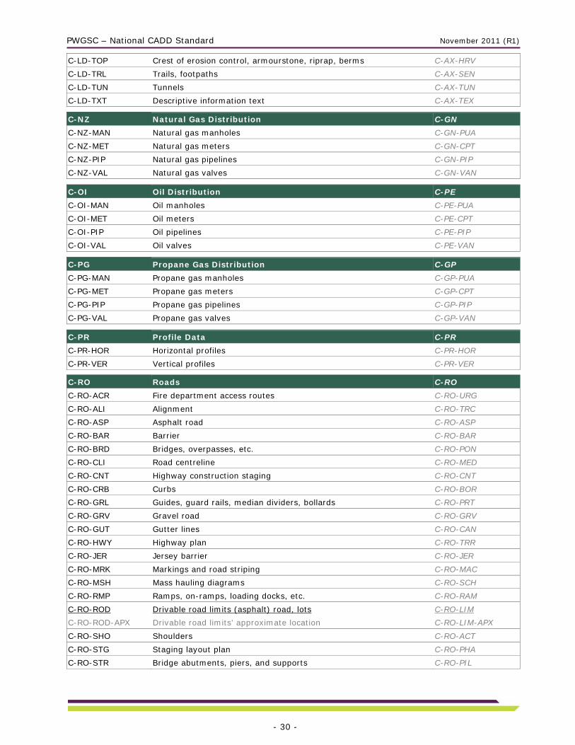
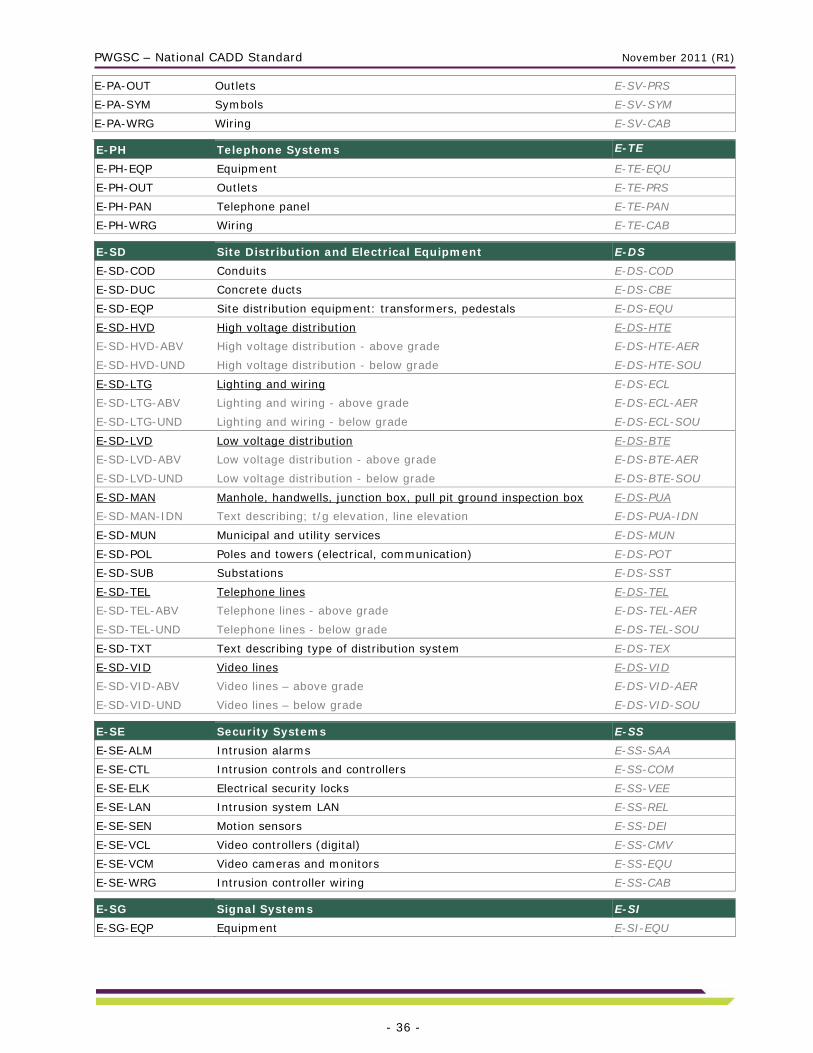
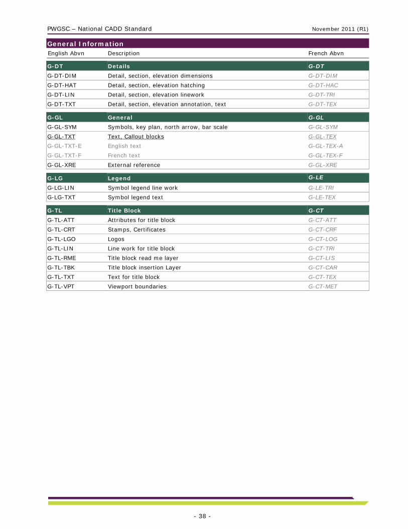
Annex A – CADD Layers The Standard Layer List below lists the most-used layer names defined under the PWGSC Layering Standard. New layer names can always be created using the field abbreviations and extensions listed in Annex B – Layer Field Descriptions. The French abbreviations are listed just as a reference and should only be used with drawings annotated in French.
A layer name may include an additional subdivision for grouping subsets of layers that represent building systems or categories of related data. Each subdivision contains a primary layer (underlined) and supplementary layers (in gray) to subdivide the information with greater precision. The use of supplementary layers is optional and depends on a drawing’s requirements.

PWGSC – National CADD Standard November 2011 (R1)
- 26 -
Architecture English Abvn Description French Abvn A-CI Circulation A-CI
A-CI-CVY Horizontal conveyors, moving sidewalks A-CI-HOR
A-CI-ELE Elevators A-CI-ELE
A-CI-ELE-BRF Lift platforms for barrier-free access A-CI-ELE-ACF
A-CI-RMP Ramps A-CI-RAM
A-CI-RMP-BRF Barrier-free ramps A-CI-RAM-ACF
A-CI-STR Stairs, stairwells, and ladders A-CI-ESC
A-CI-STR-ESC Escalators A-CI-ESC-ROU
A-CL Ceilings A-PF
A-CL-BKH Bulkheads A-PF-GYP
A-CL-FIN Ceiling finishes A-PF-FIN
A-CL-FIN-IDN Ceiling finishes description A-PF-FIN-NUI
A-CL-GRD Physical ceiling grid A-PF-TRA
A-CL-GRD-SCD Planning grid lines A-PF-TRA-SCD
A-CL-OPN Openings, penetrations, skylights A-PF-OUV A-DK Deck A-TR
A-DK-BAR Deck railings A-TR-BAR
A-DK-OLN Deck outline A-TR-CON A-DR Doors A-PO
A-DR-EXT Exterior doors, jambs, casework, swings A-PO-EXT
A-DR-EXT-IDN Exterior doors identification numbers A-PO-EXT-NUI
A-DR-INT Interior doors, jambs, casework, swings A-PO-INT
A-DR-INT-IDN Interior doors identification numbers A-PO-INT-NUI
A-DR-INT-PRT Interior doors in a partition wall A-PO-INT-CLS A-EM Emergency A-UR
A-EM-HAT General hatching A-UR-HAC
A-EM-HAT-COR Corridor hatching A-UR-HAC-COR
A-EM-HAT-STR Staircase hatching A-UR-HAC-ESC
A-EM-HAT-WAL Wall hatching A-UR-HAC-MUR
A-EM-OLN General outline A-UR-CON
A-EM-OLN-COR Corridor outline A-UR-CON-COR
A-EM-OLN-STR Staircase outline A-UR-CON-ESC
A-EM-OLN-WAL Wall outline A-UR-CON-MUR
A-EM-SYM Emergency symbols: exit signs, stairs, first aid kit location, etc. A-UR-SYM
A-EM-TXT Emergency text A-UR-TEX A-FL Floors A-PC
A-FL-CTP Countertops A-PC-CMP
A-FL-CTP-PRT Countertops on partitions A-PC-CMP-CLS
A-FL-FIN Floor finishes A-PC-FIN
A-FL-FIN-IDN Floor finishes description A-PC-FIN-NUI
A-FL-LEV Floor level changes, ramps, truck wells A-PC-NIV
A-FL-MIL Architectural specialties, casework and millwork A-PC-EBE
A-FL-OPN Openings, floor hatching A-PC-OUV

PWGSC – National CADD Standard November 2011 (R1)
- 27 -
A-FL-OVH Overhead items, skylights, overhangs, soffits A-PC-SUS
A-FL-RAS Raised floors A-PC-SUR A-GL General A-GL
A-GL-ATT Attributes A-GL-ATT
A-GL-DIM General architectural dimensions A-GL-DIM
A-GL-IDN Identification, elevation points A-GL-NUI
A-GL-RME Read Me general drawing info. A-GL-LIS
A-GL-TMP Under construction lines, temporary aids A-GL-TEM
A-GL-TXT General text (street names) A-GL-TEX A-PL Plan Information A-PN
A-PL-OLN Open-to-Below plan information outline A-PN-CON A-RF Roofs A-TO
A-RF-OLN Roofs edge and features A-TO-CON
A-RF-OPN Roof openings for fans, stacks and ducts A-TO-OUV
A-RF-OVH Overhead items, roof above, canopies, soffits A-TO-SUR
A-RF-WLK Roof boardwalks, catwalks A-TO-PAS A-WD Windows A-FN
A-WD-EXT Exterior window panes and frames A-FN-EXT
A-WD-INT Interior window panes and frames, side windows A-FN-INT
A-WD-INT-PRT Interior windows in a partition wall A-FN-INT-CLS
A-WD-OVH Overhead windows, skylights A-FN-SUR
A-WD-SIL Window sills A-FN-ALL A-WL Non-Structural Walls A-MU
A-WL-ACC Architectural or protection elements, guards A-MU-ACC
A-WL-ACC-BRF Barrier-free accessories (grab bars, etc.) A-MU-ACC-ACF
A-WL-EXT Exterior walls A-MU-EXT
A-WL-EXT-HAT Exterior walls hatching A-MU-EXT-HAC
A-WL-FIN Wall finishes A-MU-FIN
A-WL-FIN-IDN Wall finishes description A-MU-FIN-NUI
A-WL-HED Door and window headers A-MU-LIN
A-WL-HED-PRT Door and window headers on partition A-MU-LIN-CLS
A-WL-INT Interior walls A-MU-INT
A-WL-INT-LOW Interior walls - low walls A-MU-INT-BAS
A-WL-INT-LOW-PRT Interior partitions - low walls A-MU-INT-BAS-CLS
A-WL-INT-PRT Interior partition walls A-MU-INT-CLS
A-WL-OLN Wall outlines, building footprints, sheds, etc. A-MU-CON
A-WL-WSR-PRT Washroom partitions A-MU-SAT-CLS

PWGSC – National CADD Standard November 2011 (R1)
- 28 -
Bridges and Dams Engineering English Abvn Description French Abvn
B-AP Approach Slabs B-DA
B-AP-PLN Approach slabs in plan view B-DA-PLN B-DK Deck and Components B-TA
B-DK-BAR Barriers, railings B-TA-BAR
B-DK-CRB Curbs, sidewalks B-TA-BOR
B-DK-DRN Deck drains B-TA-DRA
B-DK-JNT Expansion joints B-TA-JOC
B-DK-PLN Deck plan B-TA-PLN
B-DK-REB Deck reinforcing B-TA-ACR
B-DK-STG Steel grating B-TA-GRI B-GL General B-GL
B-GL-DIM Dimensions B-GL-DIM
B-GL-HAT Hatching B-GL-HAC
B-GL-LAY Layout line work B-GL-TRI
B-GL-TXT Text B-GL-TEX B-SB Substructure B-SO
B-SB-ABU Abutments B-SO-CUL
B-SB-APR Approach slabs B-SO-APR
B-SB-BRG Bearing B-SO-POR
B-SB-FTG Footing B-SO-SEM
B-SB-LIN Bearing plan line work B-SO-TRI
B-SB-PIR Piers B-SO-PIL
B-SB-REB Substructure reinforcing B-SO-ACR B-SR Scour Protection B-PA
B-SR-GAB Gabions B-PA-GAB
B-SR-RRP Riprap B-PA-PIR B-SS Superstructure B-SP
B-SS-BEM Beams B-SP-POU
B-SS-BRC Bracing B-SP-ENT
B-SS-CTW Catwalks B-SP-PAS
B-SS-REB Superstructure reinforcing B-SP-ACR
B-SS-SNL Stringers B-SP-LON

PWGSC – National CADD Standard November 2011 (R1)
- 29 -
Civil Engineering, Site Design and Landscape Architecture English Abvn Description French Abvn
C-BH Borehole Data (Geotechnical) C-FO
C-BH-IDN Borehole identification numbers C-FO-NUI
C-BH-LOG Borehole logs and data C-FO-SCH
C-BH-SMP Soil sample locations C-FO-SON
C-BH-SPR Stratigraphic profiles C-FO-STR
C-BH-SYM Symbols C-FO-SYM
C-BH-WEL Geotechnical or environmental monitoring wells C-FO-PUA C-DI Diesel Fuel Distribution C-DI
C-DI-MAN Diesel fuel manholes C-DI-PUA
C-DI-MET Diesel fuel meters C-DI-CPT
C-DI-PIP Diesel fuel pipelines C-DI-PIP
C-DI-VAL Diesel fuel valves C-DI-VAN C-EN Environment C-EN
C-EN-CTM Contamination zone C-EN-CTM
C-EN-PLM Plume outline C-EN-CPA
C-EN-TNK Holding tank C-EN-RSV C-GL General C-GL
C-GL-PIC Inserted pictures C-GL-IMA C-HY Hydrology C-HY
C-HY-CAT Catchments area C-HY-BAV
C-HY-FLO Flow, discharge C-HY-ECO
C-HY-ICE Ice thickness C-HY-GLA C-LD Landscaping C-AX
C-LD-ANT Antenna C-AX-ANT
C-LD-ART Artwork, special features C-AX-ART
C-LD-BRD Foot bridges C-AX-PAS
C-LD-CON Concrete features, slabs C-AX-BET
C-LD-FEN Fencing C-AX-CLO
C-LD-FIL Filling zone C-AX-REM
C-LD-FLG Flagpoles C-AX-MAT
C-LD-FTN Fountains, pools C-AX-BSN
C-LD-FUR Site furnishings, benches, garbage cans, etc. C-AX-MOB
C-LD-GRA Grading C-AX-NVL
C-LD-IRR Irrigation system C-AX-IRR
C-LD-IRR-PIP Irrigation system piping C-AX-IRR-TUY
C-LD-IRR-SYM Irrigation heads, controls, valves C-AX-IRR-SYM
C-LD-RWL Retaining walls C-AX-SOU
C-LD-SPO Equipment, sports facilities, goal nets, shooting targets, etc. C-AX-EQU
C-LD-STR Stairs (not attached to buildings) C-AX-ESC
C-LD-SWK Sidewalks C-AX-TRO
C-LD-TER Terraces, courtyards, patios (not attached to buildings) C-AX-TER
C-LD-TOE Toe of erosion control, armourstone, riprap, berms C-AX-BRV
PWGSC – National CADD Standard November 2011 (R1)
- 30 -
C-LD-TOP Crest of erosion control, armourstone, riprap, berms C-AX-HRV
C-LD-TRL Trails, footpaths C-AX-SEN
C-LD-TUN Tunnels C-AX-TUN
C-LD-TXT Descriptive information text C-AX-TEX C-NZ Natural Gas Distribution C-GN
C-NZ-MAN Natural gas manholes C-GN-PUA
C-NZ-MET Natural gas meters C-GN-CPT
C-NZ-PIP Natural gas pipelines C-GN-PIP
C-NZ-VAL Natural gas valves C-GN-VAN C-OI Oil Distribution C-PE
C-OI-MAN Oil manholes C-PE-PUA
C-OI-MET Oil meters C-PE-CPT
C-OI-PIP Oil pipelines C-PE-PIP
C-OI-VAL Oil valves C-PE-VAN C-PG Propane Gas Distribution C-GP
C-PG-MAN Propane gas manholes C-GP-PUA
C-PG-MET Propane gas meters C-GP-CPT
C-PG-PIP Propane gas pipelines C-GP-PIP
C-PG-VAL Propane gas valves C-GP-VAN C-PR Profile Data C-PR
C-PR-HOR Horizontal profiles C-PR-HOR
C-PR-VER Vertical profiles C-PR-VER C-RO Roads C-RO
C-RO-ACR Fire department access routes C-RO-URG
C-RO-ALI Alignment C-RO-TRC
C-RO-ASP Asphalt road C-RO-ASP
C-RO-BAR Barrier C-RO-BAR
C-RO-BRD Bridges, overpasses, etc. C-RO-PON
C-RO-CLI Road centreline C-RO-MED
C-RO-CNT Highway construction staging C-RO-CNT
C-RO-CRB Curbs C-RO-BOR
C-RO-GRL Guides, guard rails, median dividers, bollards C-RO-PRT
C-RO-GRV Gravel road C-RO-GRV
C-RO-GUT Gutter lines C-RO-CAN
C-RO-HWY Highway plan C-RO-TRR
C-RO-JER Jersey barrier C-RO-JER
C-RO-MRK Markings and road striping C-RO-MAC
C-RO-MSH Mass hauling diagrams C-RO-SCH
C-RO-RMP Ramps, on-ramps, loading docks, etc. C-RO-RAM
C-RO-ROD Drivable road limits (asphalt) road, lots C-RO-LIM
C-RO-ROD-APX Drivable road limits’ approximate location C-RO-LIM-APX
C-RO-SHO Shoulders C-RO-ACT
C-RO-STG Staging layout plan C-RO-PHA
C-RO-STR Bridge abutments, piers, and supports C-RO-PIL

PWGSC – National CADD Standard November 2011 (R1)
- 31 -
C-RO-SWK Sidewalks C-RO-TRO
C-RO-TRL Trails, footpaths C-RO-SEN
C-RO-TUN Road tunnels, underpasses, etc. C-RO-TUN
C-RO-TXT Road description, information text C-RO-TEX C-RW Railways C-CF
C-RW-ALI Alignment C-CF-TRC
C-RW-BRD Bridges C-CF-PON
C-RW-CLI Rail centrelines C-CF-MED
C-RW-RAI Railway lines, switches C-CF-DIA
C-RW-RMP Ramps C-CF-RAM
C-RW-STR Bridge abutments, piers, trestles, and supports C-CF-PIL
C-RW-TUN Tunnels C-CF-TUN C-SA Sanitary Sewer C-ES
C-SA-CAT Drainage catch areas C-ES-BAV
C-SA-CLE Cleanout C-ES-RNT
C-SA-IND Industrial sewer C-ES-IND
C-SA-IOT Sanitary inlet outlet structure C-ES-SES
C-SA-MAN Sewer manholes, catch basins C-ES-PUA
C-SA-MAN-IDN Text regarding t/g elevation, inverts elevation, etc. C-ES-PUA-TEX
C-SA-PMP Pumping stations C-ES-PMP
C-SA-SEP Septic system C-ES-SEP
C-SA-SEP-FIL Septic field filling zone C-ES-SEP-REM
C-SA-SEP-PIP Septic field piping C-ES-SEP-TUY
C-SA-SEP-TNK Septic tank C-ES-SEP-RSV
C-SA-SEW Sewer lines system C-ES-EGO
C-SA-SEW-ABN Abandoned sanitary sewer lines C-ES-EGO-ABN
C-SA-SEW-CMB-MLI Combined main sewer lines C-ES-EGO-CMB-PRI
C-SA-SEW-CMB-SLI Combined service sewer lines C-ES-EGO-CMB-SEV
C-SA-SEW-MLI Main sanitary sewer lines C-ES-EGO-PRI
C-SA-SEW-SLI Sanitary service sewer lines C-ES-EGO-SEV
C-SA-SYM Junction symbols C-ES-SYM
C-SA-SYM-IDN Text description - type of junction C-ES-SYM-TEX
C-SA-TMT Sewage treatment areas C-ES-TEU
C-SA-TXT General text: length of sewer, slope, material, etc. C-ES-TEX C-SF Natural Site Features C-CS
C-SF-DBR Debris, rubble, loose rock and soil C-CS-DEB
C-SF-MAR Marshes, wetlands C-CS-TEH
C-SF-PIT Borrow pit C-CS-BEM
C-SF-RMN Archaeological remnants C-CS-VST
C-SF-RMN-ABV Archaeological remnants above ground C-CS-VST-AUD
C-SF-RMN-UND Archaeological remnants underground C-CS-VST-SOU
C-SF-TRE Trees, tree lines C-CS-ARB
C-SF-TRE-TXT Text describing trees C-CS-ARB-TEX
C-SF-TXT Site feature description text C-CS-TEX
C-SF-WTR Natural boundaries watercourses, shorelines C-CS-LBM

PWGSC – National CADD Standard November 2011 (R1)
- 32 -
C-SI Signs and Guideposts C-SI
C-SI-GDP Guideposts C-SI-POT
C-SI-SGL Sign layouts and details C-SI-DET
C-SI-SGN Signs C-SI-ECR
C-SI-TXT Signage text C-SI-TEX C-SV Survey Control, Non-Legal C-LV
C-SV-BEN Local bench marks C-LV-RNL
C-SV-BND Non-legal boundaries C-LV-LIP
C-SV-CHN Chainage C-LV-CHI
C-SV-CLN Radial ties, traverse lines, control lines C-LV-LCH
C-SV-CPT Control points C-LV-POA
C-SV-CPT-HOR Horizontal control points C-LV-POA-HOR
C-SV-CPT-VER Vertical control points C-LV-POA-VER
C-SV-GRD Survey grid C-LV-QUA
C-SV-HOR Horizontal alignment C-LV-HOR
C-SV-LIM Limits of contract, non-legal C-LV-LIM
C-SV-LIN Survey feature connectivity line work C-LV-TRI
C-SV-MON Found monuments (non-legal) C-LV-RAR
C-SV-PAR Parcel line work (non-legal) C-LV-PAC
C-SV-PAR-TXT Parcel text (non-legal) C-LV-PAC-TEX
C-SV-SEL Super elevation C-LV-SUE
C-SV-SPT Survey points C-LV-POL
C-SV-SPT-PNT Survey points C-LV-POL-PTS
C-SV-SPT-ELV Survey point elevation C-LV-POL-ELV
C-SV-SPT-NUM Survey point number text C-LV-POL-NUI
C-SV-SPT-DES Survey point description C-LV-POL-DES
C-SV-STA Station equation labels C-LV-STA
C-SV-STA-IDN Station labels C-LV-STA-NUI
C-SV-STA-PNT Station points C-LV-STA-PTS
C-SV-STB Setbacks C-LV-MAR
C-SV-VER Vertical alignment C-LV-VER C-SW Storm Water Drainage and Systems C-EP
C-SW-CAT Drainage catchments areas C-EP-BAV
C-SW-CUL Culverts C-EP-PON
C-SW-DCL Ditch centre lines C-EP-MED
C-SW-IOT Storm inlet outlet structure C-EP-SES
C-SW-MAN Catch basins, manholes C-EP-PUA
C-SW-MAN-IDN Manhole description text: elevation, direction C-EP-PUA-TEX
C-SW-MNG Storm water management pond C-EP-BSN
C-SW-PMP Pumping stations C-EP-PMP
C-SW-SEW Sewer lines system C-EP-EGO
C-SW-SEW-ABN Abandoned storm sewer lines C-EP-EGO-ABN
C-SW-SEW-MLI Storm main sewer lines C-EP-EGO-PRI
C-SW-SEW-SLI Storm service sewer lines C-EP-EGO-SEV
C-SW-SUB Subdrains C-EP-DRA

PWGSC – National CADD Standard November 2011 (R1)
- 33 -
C-SW-SYM Junction symbols C-EP-SYM
C-SW-SYM-IDN Junction description text C-EP-SYM-TEX
C-SW-TXT Text describing length of sewer, slopes, material C-EP-TEX C-TP Topographical Information C-TG
C-TP-MAJ Major contours C-TG-COP
C-TP-MIN Minor contours C-TG-COS
C-TP-SPT Spot elevation C-TG-POC
C-TP-SRF Surface model line work C-TG-MNT
C-TP-SRF-BRL Surface model break lines C-TG-MNT-LCO
C-TP-SRF-TXT Surface calculation text C-TG-MNT-TEX
C-TP-TOE Bank (toe) C-TG-BRV
C-TP-TOP Top of bank C-TG-HRV C-VG Vegetation C-VG
C-VG-FLW Flowers C-VG-FLR
C-VG-FLW-ANN Annual flowers C-VG-FLR-ANN
C-VG-FLW-PER Perennial flowers C-VG-FLR-VIV
C-VG-GCV Ground cover C-VG-CVS
C-VG-GCV-DEC Deciduous ground cover C-VG-CVS-CDC
C-VG-GCV-EVR Evergreen ground cover C-VG-CVS-PST
C-VG-GCV-ORN Ornamental ground cover C-VG-CVS-ORN
C-VG-GRS Grass area C-VG-PEL
C-VG-GRS-SED Seeded grass area C-VG-PEL-ESM
C-VG-GRS-SOD Sodded grass area C-VG-PEL-EGZ
C-VG-SRB Shrubs C-VG-ABT
C-VG-SRB-DEC Deciduous shrubs C-VG-ABT-CDC
C-VG-SRB-EVR Evergreen shrubs C-VG-ABT-PST
C-VG-SRB-ORN Ornamental shrubs C-VG-ABT-ORN
C-VG-TRE Trees C-VG-ARB
C-VG-TRE-DEC Deciduous trees C-VG-ARB-CDC
C-VG-TRE-ORN Flowering trees, fruit trees C-VG-ARB-ORN
C-VG-VIN Vines C-VG-VIG C-WM Water and Fire C-CE
C-WM-FHY Fire hydrants C-CE-BOI
C-WM-FRL Fire lines C-CE-CAX
C-WM-MAN Manholes, storage, valves C-CE-PUA
C-WM-MAN-IDN Text describing; t/g elevation, t/pipe elevation C-CE-PUA-TEX
C-WM-PMP Pumping stations C-CE-PMP
C-WM-RAW Raw water lines C-CE-CEN
C-WM-SYM Junction symbols C-CE-SYM
C-WM-SYM-IDN Text describing type of junction C-CE-SYM-TEX
C-WM-TXT Water main descriptive text C-CE-TEX
C-WM-WEL Water wells C-CE-PUE
C-WM-WLI Water line C-CE-CED
C-WM-WLI-MLI Water main C-CE-CED-PRI
C-WM-WLI-SLI Water service line C-CE-CED-SEV

PWGSC – National CADD Standard November 2011 (R1)
- 34 -
Electrical Systems English Abvn Description French Abvn
E-CK Clock Systems E-HO
E-CK-EQP Clock equipment E-HO-EQU
E-CK-REC Clock locations E-HO-PRS
E-CK-WRG Wiring E-HO-CAB E-DA Data Systems E-DN
E-DA-EQP Data equipment E-DN-EQU
E-DA-OUT Data outlets, jacks E-DN-PRS
E-DA-WRG Wiring E-DN-CAB E-EG Emergency Generation E-AS
E-EG-COD Conduits E-AS-COD
E-EG-EQP Emergency power generation equipment E-AS-EQU
E-EG-GEN Generators, control switchboards E-AS-GEN E-EL Emergency Lighting E-EU
E-EL-CLG Emergency luminaries ceiling-mounted E-EU-PFD
E-EL-ESG Exit signs E-EU-SOS
E-EL-EXT Emergency outside luminaries attached to buildings, poles E-EU-EXT
E-EL-WAL Emergency luminaries wall-mounted E-EU-MUR E-EP Emergency Power Equipment E-RU
E-EP-CTL Motors and controls E-RU-COM
E-EP-DCB DC battery systems E-RU-ACU
E-EP-REC Receptacles E-RU-PRS
E-EP-TEN Special tenant systems E-RU-LOC
E-EP-UPS UPS and conditioned power E-RU-ASC E-EW Emergency Power Wiring and Cabling E-CU
E-EW-CBT Cable trays, ducts, and raceways E-CU-CCC
E-EW-CLG Ceiling-mounted wiring E-CU-PFD
E-EW-CLT Control wiring for emergency lighting E-CU-COM
E-EW-EXP Exposed inside/outside wiring E-CU-EXT
E-EW-HVD High voltage wiring E-CU-HTE
E-EW-HVD-CLG High voltage in ceiling space E-CU-HTE-PFD
E-EW-LVD Low voltage wiring E-CU-BTE
E-EW-LVD-CLG Low voltage in ceiling space E-CU-BTE-PFD
E-EW-LVD-FLR Low voltage under floor E-CU-BTE-PCH
E-EW-PAN Electrical panel for emergency power E-CU-PAN
E-EW-UPS Uninterruptible power system (UPS) E-CU-ASC E-FR Electrical Fire Protection E-AI
E-FR-ELD Electromagnetic locking devices E-AI-DVE
E-FR-EQP Equipment: master fire warning panel, alarm, annunciator panels t
E-AI-EQU
E-FR-SIG Signalling devices E-AI-SIG
E-FR-SYM Electrical FP symbols: pull stations, heat, smoke detectors E-AI-DDA
E-FR-VCE Emergency voice communication E-AI-CVU
E-FR-VCE-WRG Emergency voice communication wiring E-AI-CVU-CAB

PWGSC – National CADD Standard November 2011 (R1)
- 35 -
E-FW Flat Wiring E-CP
E-FW-CBL Flat wiring cable location E-CP-CAB
E-FW-CNB Flat wiring connection boxes E-CP-BOJ E-GD Grounding E-MT
E-GC-EQP Equipment and devices (rods, bus plates) E-MT-EQU
E-GD-WRG Wiring E-MT-CAB E-LP Lightning Protection E-PT
E-LP-EQP Equipment and devices E-PT-EQU
E-LP-WRG Wiring E-PT-CAB E-NG Normal Power Generation E-AN
E-NG-COD Conduits E-AN-COD
E-NG-EQP Normal power generation equipment E-AN-EQU
E-NG-GEN Generators, control switchboard E-AN-GEN E-NL Normal Lighting E-EN
E-NL-CLG Luminaries ceiling-mounted E-EN-PFD
E-NL-CTL Lighting controls E-EN-COM
E-NL-EXT Outside luminaries attached to buildings, poles E-EN-EXT
E-NL-WAL Luminaries in workspace and wall-mounted E-EN-MUR E-NP Normal Power Equipment E-RN
E-NP-CTL Motors and controls E-RN-COM
E-NP-EQP Normal power equipment: ceiling fans, etc. E-RN-EQU
E-NP-HVD High voltage distribution E-RN-HTE
E-NP-LVD Low voltage distribution E-RN-BTE
E-NP-MEC Electrical connections to mechanical equipment E-RN-MEC
E-NP-OUT Outlets, receptacles E-RN-PRS
E-NP-PAN Electrical panels E-RN-PAN
E-NP-RAD Radiant heating panels E-RN-RAY
E-NP-TEN Special tenant systems E-RN-LOC E-NW Normal Power Wiring and Cabling E-CN
E-NW-CBT Cable trays, ducts, and raceways E-CN-CCC
E-NW-CTL Control wiring lighting E-CN-COM
E-NW-EXP Exposed inside/outside wiring E-CN-EXT
E-NW-HVD High voltage wiring E-CN-HTE
E-NW-HVD-CLG High voltage wiring in ceiling space E-CN-HTE-PFD
E-NW-LVD Low voltage wiring E-CN-BTE
E-NW-LVD-CLG Low voltage wiring in ceiling space E-CN-BTE-PFD
E-NW-LVD-FLR Low voltage under floor E-CN-BTE-PCH
E-NW-LVD-WOR Low voltage in workspace E-CN-BTE-PTV
E-NW-PST Power poles with receptacles E-CN-COL
E-NW-TEN Tenant systems in workspace E-CN-LOC
E-NW-UPS Ups and conditioned power E-CN-ASC E-PA Sound and PA Systems E-SV
E-PA-EME Emergency E-SV-URG
E-PA-EQP Sound equipment, speakers E-SV-EQU
PWGSC – National CADD Standard November 2011 (R1)
- 36 -
E-PA-OUT Outlets E-SV-PRS
E-PA-SYM Symbols E-SV-SYM
E-PA-WRG Wiring E-SV-CAB E-PH Telephone Systems E-TE
E-PH-EQP Equipment E-TE-EQU
E-PH-OUT Outlets E-TE-PRS
E-PH-PAN Telephone panel E-TE-PAN
E-PH-WRG Wiring E-TE-CAB E-SD Site Distribution and Electrical Equipment E-DS
E-SD-COD Conduits E-DS-COD
E-SD-DUC Concrete ducts E-DS-CBE
E-SD-EQP Site distribution equipment: transformers, pedestals E-DS-EQU
E-SD-HVD High voltage distribution E-DS-HTE
E-SD-HVD-ABV High voltage distribution - above grade E-DS-HTE-AER
E-SD-HVD-UND High voltage distribution - below grade E-DS-HTE-SOU
E-SD-LTG Lighting and wiring E-DS-ECL
E-SD-LTG-ABV Lighting and wiring - above grade E-DS-ECL-AER
E-SD-LTG-UND Lighting and wiring - below grade E-DS-ECL-SOU
E-SD-LVD Low voltage distribution E-DS-BTE
E-SD-LVD-ABV Low voltage distribution - above grade E-DS-BTE-AER
E-SD-LVD-UND Low voltage distribution - below grade E-DS-BTE-SOU
E-SD-MAN Manhole, handwells, junction box, pull pit ground inspection box E-DS-PUA
E-SD-MAN-IDN Text describing; t/g elevation, line elevation E-DS-PUA-IDN
E-SD-MUN Municipal and utility services E-DS-MUN
E-SD-POL Poles and towers (electrical, communication) E-DS-POT
E-SD-SUB Substations E-DS-SST
E-SD-TEL Telephone lines E-DS-TEL
E-SD-TEL-ABV Telephone lines - above grade E-DS-TEL-AER
E-SD-TEL-UND Telephone lines - below grade E-DS-TEL-SOU
E-SD-TXT Text describing type of distribution system E-DS-TEX
E-SD-VID Video lines E-DS-VID
E-SD-VID-ABV Video lines – above grade E-DS-VID-AER
E-SD-VID-UND Video lines – below grade E-DS-VID-SOU
E-SE Security Systems E-SS
E-SE-ALM Intrusion alarms E-SS-SAA
E-SE-CTL Intrusion controls and controllers E-SS-COM
E-SE-ELK Electrical security locks E-SS-VEE
E-SE-LAN Intrusion system LAN E-SS-REL
E-SE-SEN Motion sensors E-SS-DEI
E-SE-VCL Video controllers (digital) E-SS-CMV
E-SE-VCM Video cameras and monitors E-SS-EQU
E-SE-WRG Intrusion controller wiring E-SS-CAB E-SG Signal Systems E-SI
E-SG-EQP Equipment E-SI-EQU

PWGSC – National CADD Standard November 2011 (R1)
- 37 -
E-SG-OUT Outlets E-SI-PRS
E-SG-WRG Wiring E-SI-CAB E-SM Electrical Schematics E-SM
E-SM-CLK Clock system schematics E-SM-HOL
E-SM-DAS Data systems schematics E-SM-DAT
E-SM-EFP Electrical fire protection schematics E-SM-ALI
E-SM-EPR Emergency distribution schematics E-SM-ALU
E-SM-EPR-EQP Emergency power equipment E-SM-ALU-EQU
E-SM-EPR-GEN Emergency generation schematics, generators E-SM-ALU-GEN
E-SM-EPR-LTG Emergency lighting schematics E-SM-ALU-ECL
E-SM-EPR-MMS MMS tag numbers for emergency distribution E-SM-ALU-SGE
E-SM-EPR-TXT Text for emergency distribution E-SM-ALU-TEX
E-SM-EPR-WRG Emergency wiring schematics E-SM-ALU-CAB
E-SM-GND Grounding schematics E-SM-MIT
E-SM-HVD High voltage (>750v) emergency distribution E-SM-HTE
E-SM-HVD-MMS MMS tag numbers for high voltage distribution E-SM-HTE-SGE
E-SM-KRK Kirk key interlocks E-SM-KRK
E-SM-LAN Local area network schematics E-SM-REL
E-SM-LTP Lightning protection schematics E-SM-PRF
E-SM-LVD Low voltage emergency distribution E-SM-BTE
E-SM-MMS Maintenance management system (MMS) tag numbers E-SM-SGE
E-SM-MTR Metering E-SM-CPT
E-SM-MTR-EQP Metering equipment, switch board E-SM-CPT-EQU
E-SM-MTR-TXT Metering text E-SM-CPT-TEX
E-SM-MTR-WRG Metering wiring E-SM-CPT-CAB
E-SM-NPR Normal power distribution schematics E-SM-ANV
E-SM-NPR-EQP Normal power distribution equipment E-SM-ANV-EQU
E-SM-NPR-LTG Normal lighting schematics E-SM-ANV-ECL
E-SM-NPR-MMS MMS tag numbers for normal power distribution E-SM-ANV-SGE
E-SM-NPR-TXT Text for normal power distribution E-SM-ANV-TEX
E-SM-NPR-WRG Normal power wiring E-SM-ANV-CAB
E-SM-PAS Public address system schematics E-SM-COV
E-SM-SGN Signal schematic E-SM-SGN
E-SM-TEL Telephone schematics E-SM-TEL
E-SM-UPS Uninterruptible power system (UPS) E-SM-ASC
E-SM-VID Video system schematics E-SM-VID E-SY Electricity on System Furniture E-EA
E-SY-LAN LAN network jack E-EA-REL
E-SY-LTG Normal powered lighting E-EA-ECL
E-SY-OUT Electrical outlet E-EA-PRS
E-SY-PST Electrical posts on system furniture E-EA-COL
E-SY-TEL Telephone outlet E-EA-TEL E-VD Video Conferencing Systems E-VD
E-VD-EQP Equipment E-VD-EQU
E-VD-OUT Outlets E-VD-PRS
E-VD-WRG Wiring E-VD-CAB
PWGSC – National CADD Standard November 2011 (R1)
- 38 -
General Information English Abvn Description French Abvn
G-DT Details G-DT
G-DT-DIM Detail, section, elevation dimensions G-DT-DIM
G-DT-HAT Detail, section, elevation hatching G-DT-HAC
G-DT-LIN Detail, section, elevation linework G-DT-TRI
G-DT-TXT Detail, section, elevation annotation, text G-DT-TEX G-GL General G-GL
G-GL-SYM Symbols, key plan, north arrow, bar scale G-GL-SYM
G-GL-TXT Text, Callout blocks G-GL-TEX
G-GL-TXT-E English text G-GL-TEX-A
G-GL-TXT-F French text G-GL-TEX-F
G-GL-XRE External reference G-GL-XRE G-LG Legend G-LE
G-LG-LIN Symbol legend line work G-LE-TRI
G-LG-TXT Symbol legend text G-LE-TEX
G-TL Title Block G-CT
G-TL-ATT Attributes for title block G-CT-ATT
G-TL-CRT Stamps, Certificates G-CT-CRF
G-TL-LGO Logos G-CT-LOG
G-TL-LIN Line work for title block G-CT-TRI
G-TL-RME Title block read me layer G-CT-LIS
G-TL-TBK Title block insertion Layer G-CT-CAR
G-TL-TXT Text for title block G-CT-TEX
G-TL-VPT Viewport boundaries G-CT-MET

PWGSC – National CADD Standard November 2011 (R1)
- 39 -
Mechanical English Abvn Description French Abvn
H-CS Control Systems H-SR
H-CS-AIR Control air piping H-SR-AIR
H-CS-EQP Control systems equipment H-SR-EQU
H-CS-SYM Control system symbols: thermostats, humidistat, sensors, etc. H-SR-SYM
H-CS-TXT Control system text H-SR-TEX
H-CS-WRG Control wiring H-SR-CAB H-DW Domestic Water H-ED
H-DW-CLD Domestic cold water H-ED-EFR
H-DW-EQP Domestic water equipment: pumps, water softeners, filters, etc. H-ED-EQU
H-DW-FIX Plumbing fixtures H-ED-APP
H-DW-FIX-PRT Plumbing fixtures on partitions H-ED-APP-CLS
H-DW-HOT Domestic hot water H-ED-ECD
H-DW-HOT-RCL Domestic hot water recirculation H-ED-ECD-REC
H-DW-HOT-TNK Domestic hot water tanks H-ED-ECD-RSV
H-DW-ROW Reverse osmosis water (medical)
H-ED-EOI H-FP Fire Protection H-PI
H-FP-CEX Chemical extinguishing system H-PI-EXC
H-FP-CEX-EQP Chemical extinguishing equipment H-PI-EXC-EQU
H-FP-CEX-PIP Chemical extinguishing piping H-PI-EXC-TUY
H-FP-EPE Explosion-proof equipment H-PI-EQA
H-FP-EQP Fire protection equipment: fire hose cabinet, fire dampers, etc. H-PI-EQU
H-FP-FEX Foamed extinguishing system H-PI-EXM
H-FP-FEX-EQP Foamed extinguishing equipment H-PI-EXM-EQU
H-FP-FEX-PIP Foamed extinguishing piping H-PI-EXM-TUY
H-FP-SPK Sprinkler system H-PI-GIC
H-FP-SPK-EQP Sprinkler equipment H-PI-GIC-EQU
H-FP-SPK-PIP Sprinkler piping H-PI-GIC-TUY
H-FP-SPK-SYM Sprinkler system symbols: sprinkler heads, backflow preventer, etc. H-PI-GIC-SYM
H-FP-SPK-TXT Sprinkler system text H-PI-GIC-TEX
H-FP-SPK-ZNS Sprinkler system zones H-PI-GIC-ZON
H-FP-STP Standpipe system H-PI-CMG
H-FP-STP-EQP Standpipe equipment H-PI-CMG-EQU
H-FP-STP-PIP Standpipe piping H-PI-CMG-TUY
H-FP-SYM Fire protection symbols: fire extinguisher, hydrants Siamese connections, etc. H-PI-SYM
H-FP-TXT Fire protection text H-PI-TEX H-HC Heating and Cooling H-CH
H-HC-CHL Chilled water H-CH-ERF
H-HC-CHL-RET Chilled water return H-CH-ERF-RET
H-HC-CHL-SUP Chilled water supply H-CH-ERF-ALM
H-HC-CNV Convectors H-CH-CNV
H-HC-COT Cooling tower water H-CH-TRF
H-HC-COT-RET Cooling tower water return H-CH-TRF-RET
H-HC-COT-SUP Cooling tower water supply H-CH-TRF-ALM

PWGSC – National CADD Standard November 2011 (R1)
- 40 -
H-HC-GLY Glycol H-CH-GLY
H-HC-GLY-RET Glycol return H-CH-GLY-RET
H-HC-GLY-SUP Glycol supply H-CH-GLY-ALM
H-HC-HWA Heating water H-CH-ECF
H-HC-HWA-RET Heating water return H-CH-ECF-RET
H-HC-HWA-SUP Heating water supply H-CH-ECF-ALM
H-HC-HYD Hydronic equipment H-CH-HYD
H-HC-RAD Radiant heat tubing H-CH-RAY
H-HC-REF-EQP Refrigerant equipment H-CH-FRI-EQU
H-HC-RFG Refrigerant gas H-CH-GAF
H-HC-RFL Refrigerant liquid H-CH-FLF
H-HC-STM Steam H-CH-VAP
H-HC-STM-EQP Steam equipment H-CH-VAP-EQU
H-HC-STM-RET Steam condensate (return) H-CH-VAP-RET
H-HC-STM-SUP Steam supply H-CH-VAP-ALM
H-PB Plumbing H-PB
H-PB-CMA Compressed air H-PB-AIC
H-PB-CMA-EQP Compressed air equipment H-PB-AIC-EQU
H-PB-CO2 Carbon dioxide gas H-PB-CO2
H-PB-DWV Drainage waste and vent system H-PB-REV
H-PB-DWV-SYM Symbols: roof drains, floor drains, etc. H-PB-REV-SYM
H-PB-DWV-VEN Ventilating circuit, vents H-PB-REV-EVE
H-PB-DWV-WST Drainage circuit H-PB-REV-EEU
H-PB-EQP Plumbing equipment: pumps, coils motors, grease interceptor, etc. H-PB-EQU
H-PB-FOI Fuel oil H-PB-MAZ
H-PB-FOI-EQP Fuel equipment H-PB-MAZ-EQU
H-PB-FOI-RET Fuel oil return H-PB-MAZ-RET
H-PB-FOI-SUP Fuel oil supply H-PB-MAZ-ALM
H-PB-FOI-VEN Fuel oil vent H-PB-MAZ-EVE
H-PB-HEG Helium gas H-PB-HEL
H-PB-HYG Hydrogen gas H-PB-HYG
H-PB-MAN Access holes H-PB-PUA
H-PB-MEG Methane gas H-PB-MTH
H-PB-NGA Natural gas H-PB-GAN
H-PB-NIT Nitrogen gas H-PB-AZO
H-PB-OXY Oxygen gas H-PB-OXY
H-PB-PGA Propane gas H-PB-GAP
H-PB-SYM Plumbing symbols: gauges, fittings, valves elbows, unions, reducer H-PB-SYM
H-PB-VAC Cleaning system, vacuum H-PB-NET H-PP Fuel and Process Piping H-TC
H-PP-MAN Manholes fuelling stations H-TC-PUA
H-PP-MET Meters H-TC-CPT
H-PP-PIP Fuel and process piping H-TC-TUY
H-PP-PMP Pumping stations H-TC-PMP

PWGSC – National CADD Standard November 2011 (R1)
- 41 -
H-PP-TNK Fuel tanks H-TC-RSV
H-PP-VAL Valves H-TC-VAN H-SM Mechanical Schematics and Riser Diagrams H-SM
H-SM-CTL Control system schematics H-SM-COM
H-SM-DRS Duct riser diagrams H-SM-CMC
H-SM-DUC Duct schematic diagrams H-SM-COD
H-SM-PIP Piping schematic diagrams H-SM-TUY
H-SM-PRS Piping riser diagrams H-SM-CMT
H-SM-SYM Symbols H-SM-SYM
H-SM-WST Waste schematics H-SM-EEU H-VA Ventilation and Air Conditioning H-VC
H-VA-COA Combustion air ductwork H-VC-ACO
H-VA-EQP Equipment: fans, dampers, coils, filters, etc. H-VC-EQU
H-VA-EXH Exhaust air system H-VC-AEV
H-VA-EXH-DUC Exhaust air ductwork H-VC-AEV-COD
H-VA-EXH-GRI Exhaust grilles H-VC-AEV-GRI
H-VA-INS Duct insulation, acoustical lining H-VC-ISO
H-VA-OTA Outside air system H-VC-AEX
H-VA-OTA-DUC Outside air ductwork H-VC-AEX-COD
H-VA-OTA-GRI Outside air grilles H-VC-AEX-GRI
H-VA-RET Return system H-VC-REP
H-VA-RET-DUC Return ductwork H-VC-REP-COD
H-VA-RET-GRI Return grills H-VC-REP-GRI
H-VA-SUP Supply system H-VC-AMA
H-VA-SUP-DIF Supply diffusers H-VC-AMA-DIF
H-VA-SUP-DUC Supply ductwork H-VC-AMA-COD
H-VA-VAV Variable air volume boxes H-VC-DAV
H-VA-VEN Flue, vent, breaching H-VC-EVE
PWGSC – National CADD Standard November 2011 (R1)
- 42 -
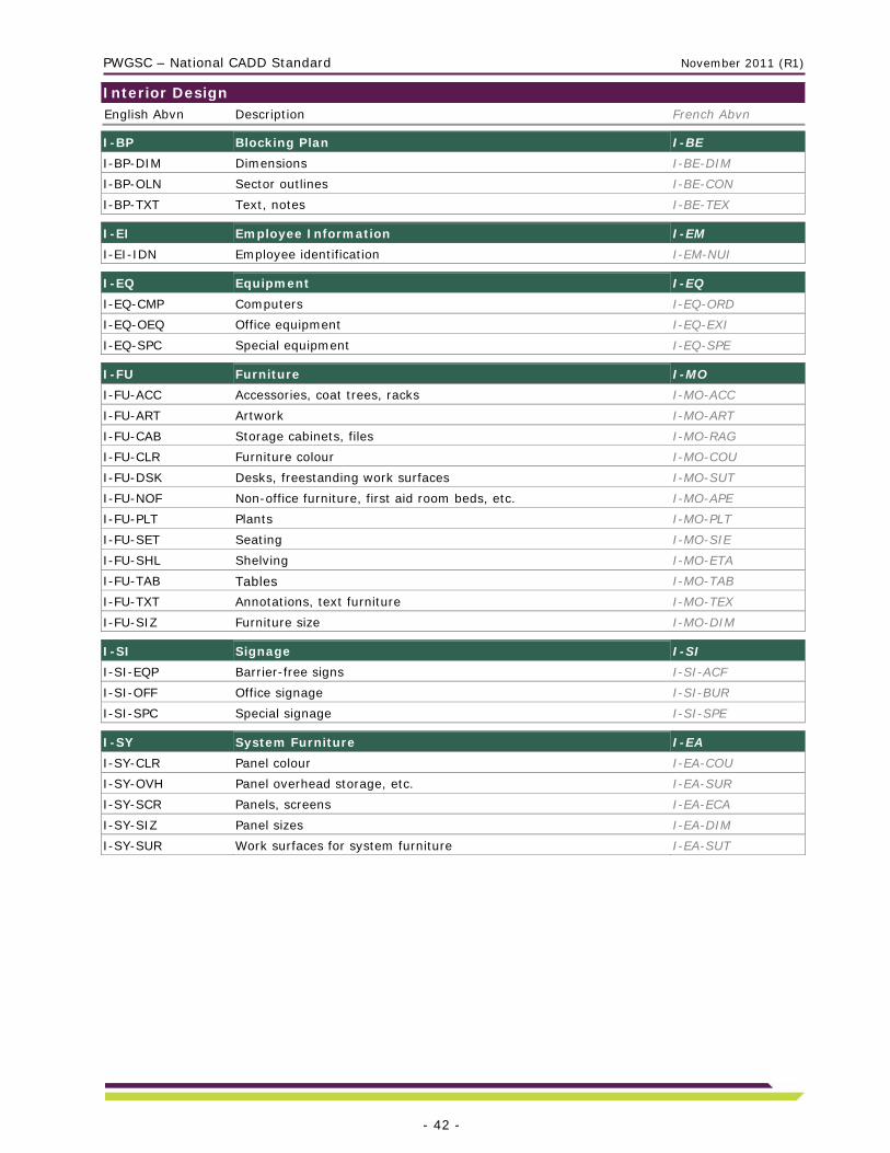
Interior Design English Abvn Description French Abvn
I-BP Blocking Plan I-BE
I-BP-DIM Dimensions I-BE-DIM
I-BP-OLN Sector outlines I-BE-CON
I-BP-TXT Text, notes I-BE-TEX I-EI Employee Information I-EM
I-EI-IDN Employee identification I-EM-NUI I-EQ Equipment I-EQ
I-EQ-CMP Computers I-EQ-ORD
I-EQ-OEQ Office equipment I-EQ-EXI
I-EQ-SPC Special equipment I-EQ-SPE I-FU Furniture I-MO
I-FU-ACC Accessories, coat trees, racks I-MO-ACC
I-FU-ART Artwork I-MO-ART
I-FU-CAB Storage cabinets, files I-MO-RAG
I-FU-CLR Furniture colour I-MO-COU
I-FU-DSK Desks, freestanding work surfaces I-MO-SUT
I-FU-NOF Non-office furniture, first aid room beds, etc. I-MO-APE
I-FU-PLT Plants I-MO-PLT
I-FU-SET Seating I-MO-SIE
I-FU-SHL Shelving I-MO-ETA
I-FU-TAB Tables I-MO-TAB
I-FU-TXT Annotations, text furniture I-MO-TEX
I-FU-SIZ Furniture size I-MO-DIM I-SI Signage I-SI
I-SI-EQP Barrier-free signs I-SI-ACF
I-SI-OFF Office signage I-SI-BUR
I-SI-SPC Special signage I-SI-SPE I-SY System Furniture I-EA
I-SY-CLR Panel colour I-EA-COU
I-SY-OVH Panel overhead storage, etc. I-EA-SUR
I-SY-SCR Panels, screens I-EA-ECA
I-SY-SIZ Panel sizes I-EA-DIM
I-SY-SUR Work surfaces for system furniture I-EA-SUT

PWGSC – National CADD Standard November 2011 (R1)
- 43 -
Legal Surveys English Abvn Description French Abvn
L-AZ Airport Zoning L-ZA
L-AZ-ZNS Zoning surfaces, runway strips, centrelines L-ZA-ZON L-CF Cadastral Fabric L-CD
L-CF-BDY Legal surveyed boundary L-CD-LIF
L-CF-DIM Parcel segment labelling, bearings, and distance L-CD-DIM
L-CF-EAS Limited interest estate, easement, right of way L-CD-DRO
L-CF-OTH Other parcels/boundaries L-CD-AUT
L-CF-STB Setbacks L-CD-MAR
L-CF-SYM Symbols: coordinate monument, control point L-CD-SYM
L-CF-TXT Parcel labelling, description, property ID, book number, etc. L-CD-TEX L-GL General L-GL
L-GL-TXT General text L-GL-TEX L-SP Legal Site Plan L-PS
L-SP-CAN Canadian boundaries L-PS-FCN
L-SP-CLS CLSR boundaries, reserves, parks L-PS-RTC
L-SP-PRO Provincial boundaries L-PS-PRV
L-SP-REG Regional and municipality boundaries L-PS-MUN L-SV Legal Survey L-LV
L-SV-CLN Radial ties, traverse lines, control lines L-LV-LCH
L-SV-GRD Survey grid L-LV-QUA
L-SV-SPT Survey points L-LV-POL
L-SV-SPT-DES Survey point description L-LV-POL-DES
L-SV-SPT-ELV Survey point elevation L-LV-POL-ELV
L-SV-SPT-NUM Survey point number text L-LV-POL-NUI
L-SV-SPT-PNT Survey points L-LV-POL-PTS
L-SV-SYM Symbols: survey pins, iron bars, etc. L-LV-SYM
L-SV-TXT Identification text L-LV-TEX

PWGSC – National CADD Standard November 2011 (R1)
- 44 -
Marine English Abvn Description French Abvn
M-BW Breakwater Features M-BL
M-BW-OLN Breakwater outline M-BL-CON
M-BW-TOE Toe of breakwater M-BL-BRV
M-BW-TOP Crest of breakwater, berms M-BL-HRV M-GL General M-GL
M-GL-DIM Dimensions M-GL-DIM
M-GL-HAT Hatching M-GL-HAC
M-GL-LAY Layout line work M-GL-TRI
M-GL-TXT Text M-GL-TEX M-NV Navigation M-NA
M-NV-BUO Buoys M-NA-BOU
M-NV-CAR Cards M-NA-SYM
M-NV-CNL Navigation channels, corridors M-NA-CNL
M-NV-EQP Floating aids, marker buoys, fog horns M-NA-EQU
M-NV-SPA Spars M-NA-MAT M-SK Skid-way, Haul-outs, Slipways M-CA
M-SK-BED Vessel beds M-CA-PLF
M-SK-BLK Anchor blocks, haul out blocks M-CA-BLC
M-SK-FTG Footings M-CA-SEM
M-SK-GUA Guards M-CA-GUA
M-SK-OLN Skid-way outline M-CA-CON
M-SK-RAI Railway M-CA-TRC
M-SK-SKD Skid timbers, skid poles M-CA-POU
M-SK-SLB Concrete slabs, precast panels M-CA-DPP
M-SK-SSP Steel sheet piling M-CA-PAL M-SN Hydrographic Survey Information, Non Legal M-RH
M-SN-DAT Chart datum contour, 0.00 m M-RH-ZDC
M-SN-DRG Dredged area or limits M-RH-LID
M-SN-HNT High normal tide M-RH-MHN
M-SN-HWL High water lines M-RH-LHM
M-SN-LNT Low normal tide M-RH-MBN
M-SN-LWL Low water lines M-RH-LBM
M-SN-MAJ Major sea bottom contours M-RH-PFM
M-SN-MIN Minor sea bottom contours M-RH-SFM
M-SN-SPT Soundings, spot elevations M-RH-SON
M-SN-SPT-ELV Survey point elevation M-RH-POL-ELV
M-SN-SPT-PNT Survey points M-RH-POL-PTS
M-SN-SPT-NUM Survey point number text M-RH-POL-NUI
M-SN-SPT-DES Survey point description M-RH-POL-DES
M-SN-TID Tide gauges, tidal equipment, tide datum M-RH-EQU

PWGSC – National CADD Standard November 2011 (R1)
- 45 -
M-WF Wharf Features M-CQ
M-WF-BEM Pile caps, beams M-CQ-POU
M-WF-BRC Bracing, wales M-CQ-ENT
M-WF-CAI Caissons M-CQ-FLO
M-WF-CRW Crown slopes, crowns M-CQ-SOM
M-WF-CTW Catwalks M-CQ-PAS
M-WF-CWK Cribwork, ballast floor M-CQ-CCV
M-WF-CWL Cope walls, cope beams M-CQ-MPC
M-WF-DRK Derricks, cranes, gallows M-CQ-GRU
M-WF-DRN Drains, scuppers M-CQ-DRA
M-WF-FND Fenders M-CQ-DEF
M-WF-FST Floating wharves M-CQ-QUF
M-WF-FTG Footings, mattresses, deck substructures M-CQ-SEM
M-WF-FWL Firewalls M-CQ-MCF
M-WF-GUA Guards M-CQ-BAR
M-WF-GWY Gangways M-CQ-PAE
M-WF-JNT Construction, control joints M-CQ-JOC
M-WF-LAD Ladders M-CQ-ECH
M-WF-MOR Mooring cleats, mooring rings, bollards M-CQ-TAA
M-WF-OLN Wharf and dolphin outlines M-CQ-CON
M-WF-PIL Piles and bents M-CQ-PIL
M-WF-SSP Steel sheet piling M-CQ-PAL
M-WF-TIE Tie rods, anchor blocks, tie back walls M-CQ-TBA

PWGSC – National CADD Standard November 2011 (R1)
- 46 -
Real Property Space Management English Abvn Description French Abvn
R-BC Building Common Areas “Accessory B” R-CB
R-BC-COR Shared public corridors R-CB-COR
R-BC-OLN General shared building outline R-CB-CON
R-BC-RMS Shared rooms R-CB-SAL R-BS Building Service Areas R-SB
R-BS-OLN General building service outline R-SB-CON
R-BS-RMS Building service rooms R-SB-SAL
R-BS-SFT Vertical shafts, elevators, stairs (takes walls over RMS) R-SB-PUV R-EX Exterior Site Areas R-EX
R-EX-OLN Exterior site areas R-EX-CON R-FC Floor Common Areas R-AE
R-FC-CNV Convectors (baseboard, radiators) R-AE-CNV
R-FC-COL Building structure, columns (interior and perimeter) R-AE-COL
R-FC-COR Primary circulation R-AE-COR
R-FC-ENC Encroachments (unusable space) R-AE-EMP
R-FC-FIR Fire egress cross over areas, fire refuge areas R-AE-SOS
R-FC-LOB Floor elevator lobbies R-AE-HAL
R-FC-OLN General outline of floor common areas R-AE-CON
R-FC-RMS Electrical, telecom, janitor’s closets R-AE-SAL
R-FC-WSR Washrooms R-AE-SAT
R-FC-WSR-BRF Accessible washrooms R-AE-SAT-ACF
R-GA Gross Area R-AB
R-GA-EXT Exterior gross area R-AB-EXT
R-GA-INT Interior gross area R-AB-INT R-GL General R-GL
R-GL-TXT Street names for space audit R-GL-TEX R-PK Parking R-ST
R-PK-0000-BRF Barrier-free parking R-ST-0000-ACF
R-PK-0000-DEP Parking number - department name (Special use only) R-ST-0000-MIN
R-PK-DIV Parking divisions R-ST-DIV
R-PK-EXT Exterior parking (Special use only) R-ST-EXT
R-PK-IDN Parking identification numbers R-ST-NUI
R-PK-INT Interior parking (Special use only) R-ST-INT
R-PK-OLN Outlines R-ST-CON
R-PK-SPC Special parking R-ST-SPE R-SU Surface Maintenance Building R-SU
R-SU-CLG Ceiling finishes R-SU-PFD
R-SU-COR Primary corridors R-SU-COR
R-SU-DEP Space allocation by department R-SU-MIN
R-SU-DIV Division of area R-SU-DIV
R-SU-EXT Exterior finishes R-SU-EXT

PWGSC – National CADD Standard November 2011 (R1)
- 47 -
R-SU-FLR Floor finishes R-SU-PCH
R-SU-FLR-HIG High-traffic area R-SU-PCH-ELV
R-SU-FLR-LOW Low-traffic area R-SU-PCH-BAS
R-SU-GRP Space allocation by group / branch R-SU-GRP
R-SU-IDN Surface identification number R-SU-NUI
R-SU-OLN Outlines R-SU-CON
R-SU-RMS Rooms R-SU-SAL
R-SU-SFT Shafts R-SU-PUV
R-SU-SPC Special surfaces R-SU-SPE
R-SU-WAL Walls R-SU-MUR
R-SU-WIN Windows R-SU-FEN R-UC User Common R-AC
R-UC-COR Shared public corridors R-AC-COR
R-UC-OLN General shared user outline R-AC-CON
R-UC-RMS Shared rooms (Conference room, day care, mail, etc.) R-AC-SAL R-US Usable R-AU
R-US-001, 002… Usable area polygons by location R-AU-001, 002
R-US-COR Primary circulation areas (Special use only) R-AU-COR
R-US-DEP Space allocation by department (Special use only) R-AU-MIN
R-US-DIV Division of areas R-AU-DIV
R-US-GRP Space allocation by group / branch (Special use only) R-AU-GRP
R-US-IDN Location identification numbers R-AU-NUI
R-US-OLN General usable outlines (Special use only) R-AU-CON
R-US-RMS Room identification numbers (Special use only) R-AU-SAL-NUI
R-US-UNT Space allocation by units (Special use only) R-AU-UNI R-ZN Zoning R-ZO
R-ZN-CLE Cleaning zoning R-ZO-NET
R-ZN-FIR Fire egress zoning R-ZO-SOS
R-ZN-SEC Security zoning R-ZO-SEU

PWGSC – National CADD Standard November 2011 (R1)
- 48 -
Structure English Abvn Description French Abvn
S-CL Ceilings S-PF
S-CL-BEM Ceiling beams S-PF-POU S-FL Floors S-PC
S-FL-BEM Floor beams S-PC-POU
S-FL-BRC Bracing S-PC-ENT
S-FL-DEK Decking, waffle S-PC-PLA
S-FL-FRM Framing S-PC-CHR
S-FL-JNT Joints, expansion, construction S-PC-JOC
S-FL-JST Joists S-PC-PLP
S-FL-OLN Floor outlines S-PC-CON
S-FL-OPN Floor openings S-PC-OUV
S-FL-SLB Floor slabs S-PC-DPP
S-FL-STR Structural landings S-PC-ESC S-FN Foundations S-FD
S-FN-BEM Pile caps, cap beams, grade beams S-FD-POU
S-FN-FIL Backfill, soil line S-FD-REM
S-FN-FTG Footings S-FD-SEM
S-FN-OLN Foundation outlines S-FD-CON
S-FN-PIL Piles, caissons, piers S-FD-PIE S-GR Structural Grid S-QU
S-GR-EXT Structural grid lines outside building S-QU-EXT
S-GR-INT Structural grid lines inside building S-QU-INT S-RF Roofs S-TO
S-RF-BEM Beams S-TO-POU
S-RF-BRC Bracing S-TO-ENT
S-RF-DEK Decking, waffle S-TO-PLA
S-RF-FRM Framing, S-TO-CHR
S-RF-JNT Joints, expansion, construction S-TO-JOC
S-RF-JST Joists S-TO-PLP
S-RF-OLN Roof outlines S-TO-CON
S-RF-OPN Roof openings S-TO-OUV
S-RF-SLB Roof slabs S-TO-DPP
S-RF-TRU Roof Trusses S-TO-FER S-WL Walls, Columns S-MU
S-WL-BRC Cross bracing S-MU-ENT
S-WL-BRG Bearing walls S-MU-POR
S-WL-COL Columns S-MU-COL
S-WL-JNT Joints, expansion, construction S-MU-JOC
S-WL-OPN Wall openings S-MU-OUV
S-WL-RWL Retaining walls S-MU-STM
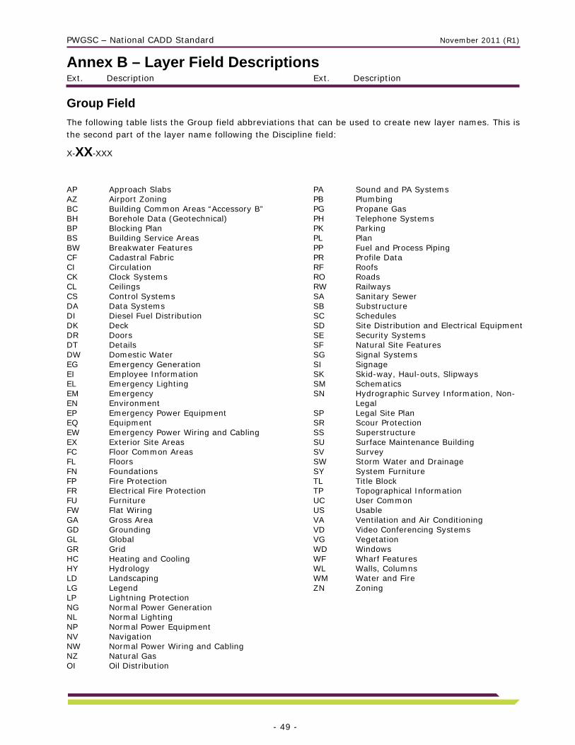
PWGSC – National CADD Standard November 2011 (R1)
Ext. Description Ext. Description
- 49 -
Annex B – Layer Field Descriptions
Group Field
The following table lists the Group field abbreviations that can be used to create new layer names. This is the second part of the layer name following the Discipline field:
X-XX-XXX
AP Approach Slabs AZ Airport Zoning BC Building Common Areas “Accessory B” BH Borehole Data (Geotechnical) BP Blocking Plan BS Building Service Areas BW Breakwater Features CF Cadastral Fabric CI Circulation CK Clock Systems CL Ceilings CS Control Systems DA Data Systems DI Diesel Fuel Distribution DK Deck DR Doors DT Details DW Domestic Water EG Emergency Generation EI Employee Information EL Emergency Lighting EM Emergency EN Environment EP Emergency Power Equipment EQ Equipment EW Emergency Power Wiring and Cabling EX Exterior Site Areas FC Floor Common Areas FL Floors FN Foundations FP Fire Protection FR Electrical Fire Protection FU Furniture FW Flat Wiring GA Gross Area GD Grounding GL Global GR Grid HC Heating and Cooling HY Hydrology LD Landscaping LG Legend LP Lightning Protection NG Normal Power Generation NL Normal Lighting NP Normal Power Equipment NV Navigation NW Normal Power Wiring and Cabling NZ Natural Gas OI Oil Distribution
PA Sound and PA Systems PB Plumbing PG Propane Gas PH Telephone Systems PK Parking PL Plan PP Fuel and Process Piping PR Profile Data RF Roofs RO Roads RW Railways SA Sanitary Sewer SB Substructure SC Schedules SD Site Distribution and Electrical Equipment SE Security Systems SF Natural Site Features SG Signal Systems SI Signage SK Skid-way, Haul-outs, Slipways SM Schematics SN Hydrographic Survey Information, Non-
Legal SP Legal Site Plan SR Scour Protection SS Superstructure SU Surface Maintenance Building SV Survey SW Storm Water and Drainage SY System Furniture TL Title Block TP Topographical Information UC User Common US Usable VA Ventilation and Air Conditioning VD Video Conferencing Systems VG Vegetation WD Windows WF Wharf Features WL Walls, Columns WM Water and Fire ZN Zoning

PWGSC – National CADD Standard November 2011 (R1)
Ext. Description Ext. Description
- 50 -
Single Layer Field and First Layer Name Extension
The following table lists the Single Layer field and First Layer Name Extension abbreviations that can be used to create new layer names. This is the third or fourth part (if required) of the layer name following the Group field:
X-XX-XXX X-XX-XXX-XXX-X
3DM 3D model components of 2D symbols ABN Abandoned ABU Abutments ABV Above ground, above grade ACC Accessories ACR Fire department access routes AIR Control air piping ALI Alignment ALM Intrusion alarms ANN Annual flowers ANT Antenna APC Approach surface (airport) APR Approach slabs APX Approximate ART Artwork ASP Asphalt ATT Attributes AWP Acid waste piping (medical) BAR Barriers, railings BDY Legal limits, fee simple, admin., control BED Vessel beds BEM Beams BEN Local benchmarks BIR Bird hazard (airport) BKH Bulkheads BLK Block BND Boundaries BRC Bracing BRF Barrier-free BRD Bridges BRG Bearing BRK Brick BRL Break lines BUO Buoys BYP By-pass box CAB Cabinet CAI Caissons CAL Callout blocks CAN Canadian boundaries CAR Cards CAT Catchments area CBL Flat wiring cable location CBT Cable trays, ducts, and raceways CEX Chemical extinguisher CHL Chilled water CHN Chainage CLD Cold water CLE Cleaning, clean out CLG Ceiling-mounted equipment, wiring, or
finishes CLI Centrelines
CLK Clock system CLN Control lines CLR Colours CLS CLSR boundaries, reserves, parks CLT Control wiring for emergency lighting CMA Compressed air CMB Combined sewers CMP Computers CNB Flat wiring connection boxes CNL Navigation channels, corridors CNT Construction CNV Convectors CO2 Carbon dioxide gas COA Combustion air ductwork COD Conduits COL Columns CON Concrete COR Corridors COT Cooling tower CPT Control points CRB Curbs CRP Carpet CRT Certificates, stamps CRW Crown slopes, crowns CTL Controls CTM Contamination (environment) CTP Countertops CTW Catwalks CUL Culverts CVY Horizontal conveyors, moving sidewalks CWL Cope walls, cope beams CWK Cribwork, ballast floor DAS Data systems schematics DAT Chart datum contour, 0.00 m DBR Debris, rubble, loose rock and soil DCB DC battery systems DCL Ditch centre lines DEC Deciduous DEK Deck DEP Space allocation by department DES Description DIF Diffusers DIG Digitized or vectorized from scanned
Image DIM Dimensions DIV Divisions DRG Dredged area or limits DRK Derricks, cranes, gallows DRN Drains, scuppers DRS Duct riser diagrams DSK Desks, work surfaces, tables

PWGSC – National CADD Standard November 2011 (R1)
Ext. Description Ext. Description
- 51 -
DUC Ducts DWV Drainage waste and vent system EAS Easement EFP Electrical fire protection schematics ELD Electromagnetic locking devices ELE Elevators ELK Electrical security locks ELV Elevation (survey points) EME Emergency ENC Encroachments (unusable space) EPE Explosion-proof equipment EPR Emergency power wiring & equipment EQP Equipment ESC Escalator ESG Exit signs EVR Evergreen EXH Exhaust EXP Exposed inside/outside wiring EXT Exterior FEN Fencing FEX Foamed extinguisher FHY Fire hydrants FIL Backfill, soil line FIN Finishes FIR Fire egress FIX Plumbing fixtures FLG Flagpoles FLO Flow, discharge FLR Floor-mounted equipment, wiring or
finishes FLW Flowers FND Fenders FOI Fuel oil FRL Fire lines FRM Framing FST Floating wharfs FTG Footing FTN Fountains, pools FUR Site furnishings, benches, garbage cans,
etc. FWL Fire walls GAB Gabions GCV Ground cover GDP Guideposts GEN Generators GLY Glycol GLZ Glass, glazing GND Grounding schematics GPS Global Positioning System GRA Grading GRD Grid GRI Grilles GRL Guides, guardrails, median dividers,
bollards GRP Space allocation by group / branch GRS Grass, lawn area GRV Gravel GUA Guards GUT Gutter lines
GWY Gangways HAT Hatching HED Door and window headers HEG Helium gas HIG High HNT High normal tide HOR Horizontal HOT Hot water HVD High voltage distribution HWA Heating water HWL High water lines HWY Highway plan HYD Hydronic equipment HYG Hydrogen gas ICE Ice thickness IDN Identification IMP Imports (Revit families) IND Industrial INS Insulation INT Interior IOT Inlet outlet IRR Irrigation system JER Jersey wall JNT Joints JST Joists KRK Kirk key interlocks LAD Ladders LAN Local area network LAY Layout line work LEV Floor level changes, ramps, truck wells LGO Logos LGT Lighting control schematics and diagrams LIM Limits LIN Line work LNT Low normal tide LOB Floor elevator lobbies LOG Borehole logs and data LOW Low LTG Normal powered lighting LTP Lightning protection schematics LVD Low voltage distribution LWL Low water lines MAJ Major contours MAN Manholes MAR Marshes, wetlands MEC Electrical connections to mechanical
equipment MEG Methane gas MET Meters MIL Architectural specialties, casework and
millwork MIN Minor contours MLI Main lines MMS Maintenance Management System MNG Storm water management pond MON Monuments MOR Mooring cleats, bollards MRK Markings and road striping MSH Mass hauling diagrams
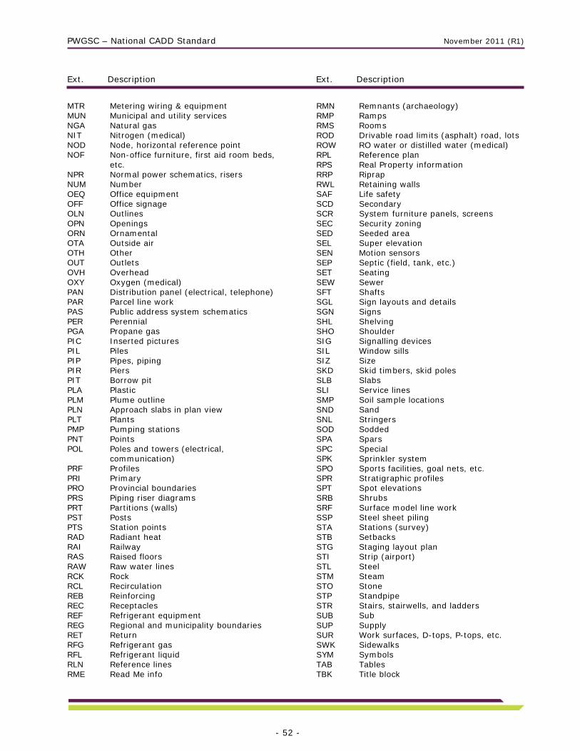
PWGSC – National CADD Standard November 2011 (R1)
Ext. Description Ext. Description
- 52 -
MTR Metering wiring & equipment MUN Municipal and utility services NGA Natural gas NIT Nitrogen (medical) NOD Node, horizontal reference point NOF Non-office furniture, first aid room beds,
etc. NPR Normal power schematics, risers NUM Number OEQ Office equipment OFF Office signage OLN Outlines OPN Openings ORN Ornamental OTA Outside air OTH Other OUT Outlets OVH Overhead OXY Oxygen (medical) PAN Distribution panel (electrical, telephone) PAR Parcel line work PAS Public address system schematics PER Perennial PGA Propane gas PIC Inserted pictures PIL Piles PIP Pipes, piping PIR Piers PIT Borrow pit PLA Plastic PLM Plume outline PLN Approach slabs in plan view PLT Plants PMP Pumping stations PNT Points POL Poles and towers (electrical,
communication) PRF Profiles PRI Primary PRO Provincial boundaries PRS Piping riser diagrams PRT Partitions (walls) PST Posts PTS Station points RAD Radiant heat RAI Railway RAS Raised floors RAW Raw water lines RCK Rock RCL Recirculation REB Reinforcing REC Receptacles REF Refrigerant equipment REG Regional and municipality boundaries RET Return RFG Refrigerant gas RFL Refrigerant liquid RLN Reference lines RME Read Me info
RMN Remnants (archaeology) RMP Ramps RMS Rooms ROD Drivable road limits (asphalt) road, lots ROW RO water or distilled water (medical) RPL Reference plan RPS Real Property information RRP Riprap RWL Retaining walls SAF Life safety SCD Secondary SCR System furniture panels, screens SEC Security zoning SED Seeded area SEL Super elevation SEN Motion sensors SEP Septic (field, tank, etc.) SET Seating SEW Sewer SFT Shafts SGL Sign layouts and details SGN Signs SHL Shelving SHO Shoulder SIG Signalling devices SIL Window sills SIZ Size SKD Skid timbers, skid poles SLB Slabs SLI Service lines SMP Soil sample locations SND Sand SNL Stringers SOD Sodded SPA Spars SPC Special SPK Sprinkler system SPO Sports facilities, goal nets, etc. SPR Stratigraphic profiles SPT Spot elevations SRB Shrubs SRF Surface model line work SSP Steel sheet piling STA Stations (survey) STB Setbacks STG Staging layout plan STI Strip (airport) STL Steel STM Steam STO Stone STP Standpipe STR Stairs, stairwells, and ladders SUB Sub SUP Supply SUR Work surfaces, D-tops, P-tops, etc. SWK Sidewalks SYM Symbols TAB Tables TBK Title block
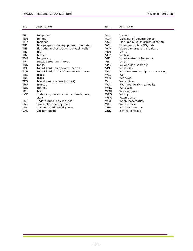
PWGSC – National CADD Standard November 2011 (R1)
Ext. Description Ext. Description
- 53 -
TEL Telephone TEN Tenant TER Terraces TID Tide gauges, tidal equipment, tide datum TIE Tie rods, anchor blocks, tie-back walls TIL Tile TIM Timber TMP Temporary TMT Sewage treatment areas TNK Tanks TOE Toe of bank, breakwater, berms TOP Top of bank, crest of breakwater, berms TRE Trees TRL Trails TRS Transitional surface (airport) TRU Trusses TUN Tunnels TXT Text UCD Underlying cadastral fabric, deeds, lots,
plans UND Underground, below grade UNT Space allocation by units UPS Ups and conditioned power VAC Vacuum piping
VAL Valves VAV Variable air volume boxes VCE Emergency voice communication VCL Video controllers (Digital) VCM Video cameras and monitors VEN Vents VER Vertical VID Video system schematics VIN Vines VPC Valve pump chamber VPT Viewports WAL Wall-mounted equipment or wiring WEL Well WIN Windows WLI Water lines WLK Roof boardwalks, catwalks WNG Wing wall WOR Working area WRG Wiring WSR Washrooms WST Waste schematics WTR Watercourse XRE External reference ZNS Zoning surfaces

PWGSC – National CADD Standard November 2011 (R1)
Ext. Description Ext. Description
- 54 -
Second Layer Name Extension
The following table lists the Second Layer Name Extension abbreviations that can be used to create new layer names. This is the fourth or fifth part of the layer name following the Single Layer field or First Layer Name Extension:
X-XX-XXX--X X-XX-XXX-XXX-X 1 to 9 Options or Phases 1 to 9 A English Text (Anglais) B As Built (As Constructed) E Existing F French Text M To be Moved or Relocated N New P Planned or Proposed S Base X To Be Removed

PWGSC – National CADD Standard November 2011 (R1)
- 55 -
Annex C – Pen and Colour Assignment Tables
Atlantic Region
Pen No. Line
Width %
Intensity Printed Colour Width
Sample
1 (Red) 0.25 100% Black
2 (Yellow) 0.7 100% Black
3 (Green) 0,3 100% Black
4 (Cyan) 0,4 100% Black
5 (Blue) 1 100% Black
6 (Magenta) 0,3 100% Black
7 (White) 0.5 100% Black
8 (Gray) 0.5 100% Black
9 0.25 50% Black
10 0.25 100% Black
11 0.3 100% Black
12 0.4 100% Black
13 0.1 100% Black
14 0.4 100% Black
15 0.5 100% Black
16-249 0.3 100% AutoCAD Colour
250 0.3 60% Gray tone
251 0.3 50% Gray tone
252 0.3 40% Gray tone
253 0.3 30% Gray tone
254 0.3 20% Gray tone
255 0.3 10% Gray tone
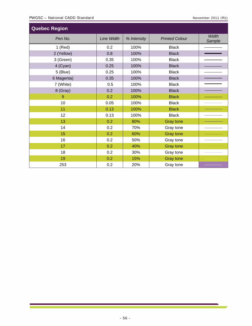
PWGSC – National CADD Standard November 2011 (R1)
- 56 -
Quebec Region
Pen No. Line Width % Intensity Printed Colour Width
Sample
1 (Red) 0.2 100% Black
2 (Yellow) 0.8 100% Black
3 (Green) 0.35 100% Black
4 (Cyan) 0.25 100% Black
5 (Blue) 0.25 100% Black
6 Magenta) 0.35 100% Black
7 (White) 0.5 100% Black
8 (Gray) 0.2 100% Black
9 0.2 100% Black
10 0.05 100% Black
11 0.13 100% Black
12 0.13 100% Black
13 0.2 80% Gray tone
14 0.2 70% Gray tone
15 0.2 60% Gray tone
16 0.2 50% Gray tone
17 0.2 40% Gray tone
18 0.2 30% Gray tone
19 0.2 15% Gray tone
253 0.2 20% Gray tone

PWGSC – National CADD Standard November 2011 (R1)
- 57 -
Ontario Region
Pen No. Line Width % Intensity Printed Colour Width
Sample
1 (Red) 0.25 100% Black
2 (Yellow) 0.18 100% Black
3 (Green) 0.35 100% Black
4 (Cyan) 0.25 100% Black
5 (Blue) 0.06 100% Black
6 Magenta) 0.35 100% Black
7 (White) 0.35 100% Black
8 (Gray) 0.18 100% Black
9 0.18 100% Black
10 0.18 100% Black
11 0.25 100% Black
12 0.25 100% Black
13 0.06 100% Black
14 0.6 100% Black
15 0.7 100% Black
16 0.25 100% 251 (Medium-dark gray)
17 0.35 100% 251 (Medium-dark gray)
18 0.5 100% 251 (Medium-dark gray)
19 0.7 100% 251 (Medium-dark gray)
20 0.25 100% Pen colour
21 - 24 0.25 100% Pen colour
25 0.18 100% Black
26-29 0.25 100% Pen colour
30 0.5 100% Black
40 0.25 100% Pen colour
80 0.25 100% Pen colour
100 0.25 100% 253 (Gray)
101 0.35 100% 253 (Gray)
102 0.5 100% 253 (Gray)
103 0.7 100% 253 (Gray)
104 0.25 100% 250 (Dark gray)
105 0.35 100% 250 (Dark gray)
106 0.5 100% 250 (Dark gray)
107 0.7 100% 250 (Dark gray)
108-109 0.25 100% Pen colour
110 0.12 100% Black
111-149 0.25 100% Pen colour
150 0.06 100% Object colour
151-210 0.25 100% Pen colour
211 1 100% Black
212 1.5 100% Black
213 2 100% Black
214-255 0.25 100% Pen colour

PWGSC – National CADD Standard November 2011 (R1)
- 58 -
National Capital Area (NCA)
Pen No. Line Width %
Intensity Printed Colour
Width Sample
1 (Red) 0.35 100% Black
2 (Yellow) 0.7 100% Black
3 (Green) 0.25 100% Black
4 (Cyan) 0.18 100% Black
5 (Blue) 0.5 100% Black
6 Magenta) 0.35 100% Black
7 (White) 0.25 100% Black
8 (Gray) 0.05 100% Black
9 0.15 50% Dark gray
10 0.15 100% Black
11 0.1 100% Black
12 0.15 100% Black
13 0.2 100% Black
14 0.25 100% Black
15 0.35 100% Black
16 0.45 100% Black
17 0.5 100% Black
18 0.7 100% Black
19 1 100% Black
50 0.5 100% Black
90 0.25 100% Black
130 0.15 100% Black
170 0.35 100% Black
210 0.2 100% Black
20, 60, 100, 140, 180, 220 0.15 100% Black
30, 70, 110, 150, 190, 230 0.25 100% Black
40, 80, 120, 160, 200, 240 0.35 100% Black
From 21 to 241 increment of 10 (21, 31, etc.) 0.1 100% Black
From 22 to 242 increment of 10 (22, 32, etc.) 0.15 100% Black
From 23 to 243 increment of 10 (23, 33, etc.) 0.2 100% Black
From 24 to 244 increment of 10 (24, 34, etc.) 0.25 100% Black
From 25 to 245 increment of 10 (25, 35, etc.) 0.35 100% Black
From 26 to 246 increment of 10 (26, 36, etc.) 0.45 100% Black
From 27 to 247 increment of 10 (27, 37, etc.) 0.5 100% Black
From 28 to 248 increment of 10 (28, 38, etc.) 0.7 100% Black
From 29 to 249 increment of 10 (29, 39, etc.) 1 100% Black
250 0.18 50% Dark gray
251 0.18 40% Medium-dark gray
252 0.18 30% Gray
253 0.18 20% Medium-light gray
254 0.18 10% Light gray
255 0.18 white White

PWGSC – National CADD Standard November 2011 (R1)
- 59 -
PWGSC Western
No. Line
Width %
Intensity Printed Colour Width Sample
1 (Red) 0.25 100% black
2 (Yellow) 0.35 100% black
3 (Green) 0.15 100% black
4 (Cyan) 0.5 100% black
5 (Blue) 0.25 100% black
6 (Magenta) 0.7 100% black
7 (White) 0.35 100% black
8 (Gray) 0.35 55% Gray tone
9 0.25 100% black
10 0.35 100% black
11 0.1 100% black
12 1 100% black
13 0.25 100% black
14 0.35 100% black
15 0.25 100% black
16 – 29 , 140 - 149 0.05 100% black
30 – 49 , 150 - 159 0.1 100% black
50 – 69 , 160 - 179 0.15 100% black
70 – 89 , 180 - 199 0.25 100% black
90 - 109 , 200 - 219 0.35 100% black
110 – 119 , 220 - 229 0.5 100% black
120 – 129 , 230 - 239 0.7 100% black
130 – 131 , 240 - 243 1 100% black
132 , 244 - 246 1.5 100% black
133 , 247 - 248 2 100% black
134 0.2 55% Gray tone
135 0.2 50% Gray tone
136 0.2 45% Gray tone
137 0.2 40% Gray tone
138 0.2 35% Gray tone
139 0.2 30% Gray tone
249 0.35 65% Gray tone
250 0.35 60% Gray tone
251 0.35 55% Gray tone
252 0.35 50% Gray tone
253 0.35 45% Gray tone
254 0.35 40% Gray tone
255 0.35 35% Gray tone
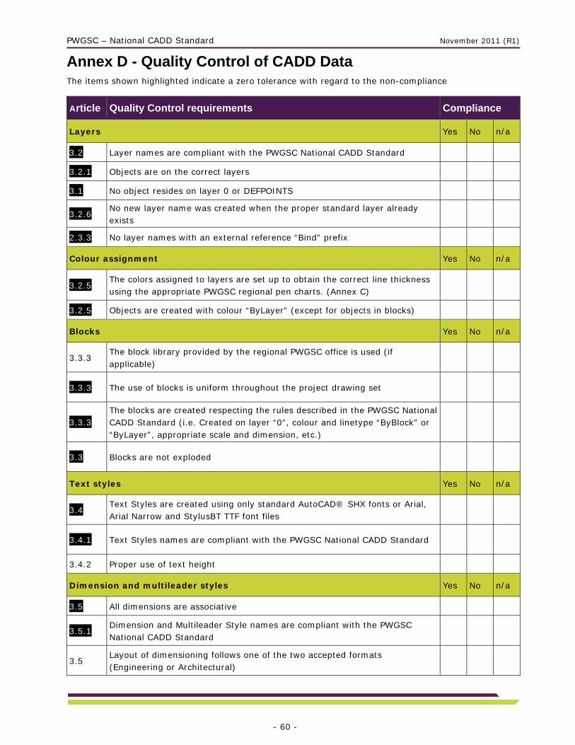
PWGSC – National CADD Standard November 2011 (R1)
- 60 -
Annex D - Quality Control of CADD Data The items shown highlighted indicate a zero tolerance with regard to the non-compliance
Article Quality Control requirements Compliance
Layers Yes No n/a
3.2 Layer names are compliant with the PWGSC National CADD Standard
3.2.1 Objects are on the correct layers
3.1 No object resides on layer 0 or DEFPOINTS
3.2.6 No new layer name was created when the proper standard layer already exists
2.3.3 No layer names with an external reference “Bind” prefix
Colour assignment Yes No n/a
3.2.5 The colors assigned to layers are set up to obtain the correct line thickness using the appropriate PWGSC regional pen charts. (Annex C)
3.2.5 Objects are created with colour “ByLayer” (except for objects in blocks)
Blocks Yes No n/a
3.3.3 The block library provided by the regional PWGSC office is used (if applicable)
3.3.3 The use of blocks is uniform throughout the project drawing set
3.3.3 The blocks are created respecting the rules described in the PWGSC National CADD Standard (i.e. Created on layer “0”, colour and linetype “ByBlock” or “ByLayer”, appropriate scale and dimension, etc.)
3.3 Blocks are not exploded
Text styles Yes No n/a
3.4 Text Styles are created using only standard AutoCAD® SHX fonts or Arial, Arial Narrow and StylusBT TTF font files
3.4.1 Text Styles names are compliant with the PWGSC National CADD Standard
3.4.2 Proper use of text height
Dimension and multileader styles Yes No n/a
3.5 All dimensions are associative
3.5.1 Dimension and Multileader Style names are compliant with the PWGSC National CADD Standard
3.5 Layout of dimensioning follows one of the two accepted formats (Engineering or Architectural)

PWGSC – National CADD Standard November 2011 (R1)
- 61 -
Linetypes and hatch patterns Yes No n/a
3.6 Only standard AutoCAD® and/or PWGSC linetypes / hatch patterns are used
3.6 Linetypes and hatch patterns are metric
3.6 Linetype display variables are set up correctly (i.e. LTSCALE, PSLTSCALE)
External references and raster images Yes No n/a
2.3.3 Drawings do not contain any external reference (except if certain conditions are met and are inserted with path type set to “No Path”)
2.3.4 Raster images and related coordinates information files used in the drawings are included in the submission
Drawing set up and page layout Yes No n/a
3.7.1 The appropriate PWGSC regional title blocks are inserted in the layouts at coordinates (0,0,0) with scale factor of 1 and rotation angle of 0
3.7.1 Only one title block is inserted per layout
3.7.1 Title blocks are not exploded
3.7.2 Title blocks contain all the required information
3.1 Viewports are set to the preferred scale and locked
3.7.3 Each plan, section, detail, elevation, etc. is accompanied by a heading, the appropriate graphic scale and, if required, a north arrow
3.7 Annotations objects such as notes, dimensions, hatch patterns, linetypes, blocks, etc are scaled accordingly to match final viewport or block insertion scaling
System of measurement and coordinate system Yes No n/a
3.8 Drawings are modeled at full-size using metric units in the model space. Buildings/structures plans and details are in millimeters. Site plans are in meters
2.3.1 The coordinate systems integrity is maintained for 2D drawings
Drawing Presentation Yes No n/a
3.0 Good drafting practices are used in the project to make the drawings easy to interpret: good positioning of annotations and dimensions, use of legends and schedules, layout of structural grid and cross-referencing bubbles.
3.0 A key plan is placed in the title sheet that locates the structure for large projects
3.1 Lines are drawn in an orthogonal mode when appropriate to the drawing
3.1 Vector endpoint intersections are drawn with closed corners
3.0 Drawings do not contain unnecessary frozen or off layers For Tender and As-built drawings

PWGSC – National CADD Standard November 2011 (R1)
- 62 -
File presentation Yes No n/a
3.1 Drawings are purged of all definitions that are not used
3.1 Drawings do not contain any object definitions without geometry, such as empty text or blocks without objects
3.1 Drawings do not contain errors that are detectable using the Audit command
4.0 Drawing files are named according to the appropriate PWGSC regional standard. When there is no regional naming convention, names are arranged in a logical format
2.4.1 The files are not compressed in EXE format, not password-protected, do not contain any electronic signature or hyperlink
3.1 Drawings are saved with properly formatted Page Setup and the main layout zoomed out and active
As-built drawings contains engineering/architect’s stamps for certification (Ontario region)
PWGSC – National CADD Standard November 2011 (R1)
- 63 -
Annex E – Glossary “As-built” shall mean a set of construction drawings reflecting on-site changes required during the project as well as the original design intent.
“AutoCAD®” shall mean the CADD software developed by Autodesk® Inc.
“Base plan” shall mean a clean, two-dimensional floor plan of a building drawn from field surveys containing all pertinent graphic information. The intent is to use base plan files for project drawings, then update them once a project is complete and the area affected is re-measured.
“CADD” shall mean Computer-Aided Design and Drafting.
“CLSR” shall mean Canada Lands Survey Records.
“Layers” shall mean the AutoCAD® system of dividing drawing elements.
“Legacy drawings” shall mean older hardcopy drawings, microfiche aperture cards not in digital format, or older CADD files not produced to the present standard.
“PWGSC” shall mean the Department of Public Works and Government Services Canada.
“RPB” shall mean Real Property Branch, a branch of PWGSC.