Purchase and Acceptance of Type H Tightlock Coupler Systems
26
APTA STANDARDS DEVELOPMENT PROGRAM RECOMMENDED PRACTICE American Public Transportation Association 1300 I Street, NW, Suite 1200 East, Washington, DC 20005 APTA PR-M-RP-003-98, Rev. 2 First Published: Jan. 22, 1998 First Revision: Feb. 13, 2004 Second Revision: Sept. 17, 2020 PRESS Mechanical Working Group This document represents a common viewpoint of those parties concerned with its provisions, namely transit operating/planning agencies, manufacturers, consultants, engineers, and general interest groups. The application of any recommended practices or guidelines contained herein is voluntary. APTA standards are mandatory to the extent incorporated by an applicable statute or regulation. In some cases, federal and/or state regulations govern portions of a transit system’s operations. In cases where this is a conflict or contradiction between an applicable law or regulation and this document, consult with a legal advisor to determine which document takes precedence. © 2020 The American Public Transportation Association (APTA). No part of this publication may be reproduced in any form, in an electronic retrieval system or otherwise, without prior written permission of APTA. Purchase and Acceptance of Type H Tightlock Coupler Systems Abstract: This recommended practice covers material, purchase and acceptance requirements for Type H Tightlock coupler systems and their parts. Keywords: radial connections, specification M-206-97, Type H Tightlock couplers, yokes Summary: This document details material, purchase and acceptance requirements for Type H Tightlock coupler systems, including couplers, coupler yokes, draft gear followers, radial connection castings, shank pins, yoke pins, bushings and other parts. This recommended practice was titled “Inspection and Maintenance of Type H Tightlock Couplers” in the previous publication of this document. Scope and purpose: The purpose of this recommended practice is to describe the minimum recommended requirements for manufacturing of new cast-steel, Tightlock couplers and components, including but not limited to: casting process/steel grades, foundry qualifications, welding and heat treating, and gage requirements. These recommended practices are the minimum required to ensure interchangeability and interoperability among standard coupler manufacturers as well as interoperability with standard AAR couplers.
Transcript of Purchase and Acceptance of Type H Tightlock Coupler Systems

A P T A S T A N D A R D S D E V E L O P M E N T P R O G R A M
RECOMMENDED PRACTICE American Public Transportation Association
1300 I Street, NW, Suite 1200 East, Washington, DC 20005
APTA PR-M-RP-003-98, Rev. 2 First Published: Jan. 22, 1998 First Revision: Feb. 13, 2004 Second Revision: Sept. 17, 2020 PRESS Mechanical Working Group
This document represents a common viewpoint of those parties concerned with its provisions, namely transit operating/planning agencies, manufacturers, consultants, engineers, and general interest groups. The application of any recommended practices or guidelines contained herein is voluntary. APTA standards are mandatory to the extent incorporated by an applicable statute or regulation. In some cases, federal and/or state regulations govern portions of a transit system’s operations. In cases where this is a conflict or contradiction between an applicable law or regulation and this document, consult with a legal advisor to determine which document takes precedence. © 2020 The American Public Transportation Association (APTA). No part of this publication may be reproduced in any form, in an electronic retrieval system or otherwise, without prior written permission of APTA.
Purchase and Acceptance of Type H Tightlock Coupler Systems Abstract: This recommended practice covers material, purchase and acceptance requirements for Type H Tightlock coupler systems and their parts.
Keywords: radial connections, specification M-206-97, Type H Tightlock couplers, yokes
Summary: This document details material, purchase and acceptance requirements for Type H Tightlock coupler systems, including couplers, coupler yokes, draft gear followers, radial connection castings, shank pins, yoke pins, bushings and other parts. This recommended practice was titled “Inspection and Maintenance of Type H Tightlock Couplers” in the previous publication of this document.
Scope and purpose: The purpose of this recommended practice is to describe the minimum recommended requirements for manufacturing of new cast-steel, Tightlock couplers and components, including but not limited to: casting process/steel grades, foundry qualifications, welding and heat treating, and gage requirements. These recommended practices are the minimum required to ensure interchangeability and interoperability among standard coupler manufacturers as well as interoperability with standard AAR couplers.

© 2020 American Public Transportation Association | ii
Table of Contents
Participants................................................................................................................................................... iv Introduction .................................................................................................................................................. vi
1. Basis of approval ..................................................................................................................................... 1 1.1 Manufacturers, foundries and materials .................................................................................................... 1 1.2 Standard designs ...................................................................................................................................... 1 1.3 Non-standard designs ............................................................................................................................... 1
2. Basis of purchase and acceptance ......................................................................................................... 2 2.1 Cast steel ................................................................................................................................................. 2 2.2 Cast steel knuckles and locks ................................................................................................................... 2 2.3 Certification............................................................................................................................................. 2 2.4 Records ................................................................................................................................................... 2
3. Cast steel manufacture ........................................................................................................................... 2
4. Mechanical properties and tests ............................................................................................................. 2
5. Inspection ................................................................................................................................................ 2 5.1 Grouping ................................................................................................................................................. 2 5.2 Visual inspection ..................................................................................................................................... 2 5.3 Casting integrity ...................................................................................................................................... 4 5.4 Wall thickness ......................................................................................................................................... 4 5.5 Proof tests................................................................................................................................................ 4 5.6 Yokes ...................................................................................................................................................... 5 5.7 Weld repair .............................................................................................................................................. 5 5.8 Wrought steel parts .................................................................................................................................. 5 5.9 Weights ................................................................................................................................................... 7 5.10 Gaging ................................................................................................................................................... 7 5.11 Coupler operation ................................................................................................................................ 10 5.12 Finish .................................................................................................................................................. 11 5.13 Lubrication .......................................................................................................................................... 11 5.14 Storage ................................................................................................................................................ 11 5.15 Markings ............................................................................................................................................. 12 5.16 Purchaser’s inspection ......................................................................................................................... 14 References................................................................................................................................................... 18 Abbreviations and acronyms ........................................................................................................................ 18 Summary of document changes ................................................................................................................... 18 Document history ........................................................................................................................................ 19
Appendix A (informative): Approval requirements for special design couplers, coupler parts, yokes and draft gear followers ............................................................................................................................ 20

© 2020 American Public Transportation Association | iii
List of Figures and Tables Figure 1 Critical Areas of Inspection ............................................................................................................ 3 Figure 2 Type H Tightlock Coupler Head .................................................................................................... 4 Table 1 Grade E Steel Static Tension Requirements ..................................................................................... 5 Table 2 Heat Treatment After Weld Repair .................................................................................................. 5 Figure 3 Dimensions and Tolerances for CH80/CH81 Coupler Shank, Yoke Pins and Bushings ................... 6 Table 3 Weight Limits ................................................................................................................................. 7 Table 4 Gages to Ensure Interchangeability of Head and Parts–Class 1 Inspector’s Gages ............................ 8 Table 5 Gages to Ensure Interchangeability of Shank–Class 1 Inspector’s Gages .......................................... 9 Table 6 Gages to Ensure Interchangeability of Yokes, Shank Butt, Radial Connection and Radial Connection Seat–Class 1 Inspector’s Gages.................................................................................. 9 Table 7 Class 2- Checking Gages for Head and Parts .................................................................................. 10 Figure 4 Coupler Inspection Operating Rod ............................................................................................... 10 Figure 5 Markings for Couplers and Components ....................................................................................... 12 Figure 6 Markings for Yokes and Attachments ........................................................................................... 13 Figure 7 Type H Tightlock Coupler Rotary Operating for Passenger Cars and Locomotives, CH81E .......... 14 Figure 8 Type H Tightlock Yoke and Radial Connection for Passenger Service, CY50/CY65 and Y25 ...... 15 Figure 9 Type H Tightlock Coupler for Passenger Service, H5401E ........................................................... 16 Figure 10 Type H Tightlock Coupler for Passenger Service, H7308E ......................................................... 17

© 2020 American Public Transportation Association | iv
Participants The American Public Transportation Association greatly appreciates the contributions of the Coupler Sub-Working Group of the PRESS Mechanical Working Group, which provided the primary effort in the drafting of this document.
At the time this recommended practice was completed, the sub-working group included the following members:
Scott Kramer, Arcosa, Sub-Working Group Lead
Rick Askey, Greenbrier Rail Services B.A. “Brad” Black, Virginkar & Associates Michael Burshtin, Amtrak Joshua Coran, Talgo Richard Curtis, Curtis Engineering Consulting Svc. Gary Fairbanks, Federal Railroad Administration Joe Gagliardino, Arcosa James Herzog, LTK Engineering Services Paul Jamieson, SNC-Lavalin Rail & Transit Ken Johnson, Greenbrier Rail Services
Daniel Luskin, Amtrak Francesco Maldari, MTA Long Island Rail Road Joe Patterson, Amsted Rail John Pearson, LTK Engineering Services Brian Pitcavage, LTK Engineering Services Jonathan Sunde, Strato Jeff Thompson, SEPTA Matthew Todt, Amsted Rail Kristian Williams, Amtrak Reggie Wingate, Knorr Brake
At the time this recommended practice was updated, the PRESS Mechanical Working Group included the following members:
David Warner, SEPTA, Chair Rudy Vazquez, Amtrak, Vice Chair
Paul Jamieson, SNC-Lavalin Rail & Transit, Secretary
Mohamed Alimirah, Metra Carl Atencio, Denver Transit Operators Frank Banko, WSP USA Michael Barnes, Jacobs David Bennett, Capital Metro Jonathan Bernat, New York Air Brake Allen Bieber, ACB RailTech Services B.A. “Brad” Black, Virginkar & Associates Stephen Bonina, WSP USA Glenn Brandimarte, ORX Rail Tony Brown, MTA of Harris County Richard Bruss, retired Michael Burshtin, Amtrak Greg Buzby, SEPTA Elvin Calderon, Denver Transit Operators Dennis Cabigting, STV Paul Callaghan, Transport Canada Gordon Campbell, Crosslinx Transit Solutions
Kevin Carmody, STV David Carter, New Jersey Transit Steve Cavanaugh, Metrolinx (GO Transit) Steve Chrismer, Amtrak Dion Church, SNC Lavalin Rail & Transit John Condrasky, Wabtec Joshua Coran, Talgo Michael Craft, Amtrak Brian Creely, Siemens Mobility Brendan Crowley, New York Air Brake Ryan Crowley, SNC-Lavalin Rail & Transit Richard Curtis, Curtis Engineering Consulting Svc. Steven Dedmon, Standard Steel Joe Di Liello, VIA Rail Canada David Diaz, LTK Engineering Services Matthew Dick, ENSCO Rail Adam Eby, Amtrak Phillippe Etchessahar, Alstom Transport

© 2020 American Public Transportation Association | v
Gary Fairbanks, Federal Railroad Administration Robert Festa, MTA Long Island Rail Road Steve Finegan, SNC-Lavalin Rail & Transit Gavin Fraser, Jacobs Francesco Fumarola, Alstom Transport Edward Gacsi, New Jersey Transit Joe Gagliardino, Arcosa Sebastien Geraud, Alstom Transport Jeffrey Gordon, Federal Railroad Administration Guillaume Ham-Livet, Alstom Transport Eric Harden, New York Air Brake Nick Harris, LTK Engineering Services Jasen Haskins, SNC-Lavalin Rail & Transit Elizabeth Hensley, Wabtec James Herzog, LTK Engineering Services Kenneth Hesser, LTK Engineering Services Lew Hoens, MTA Metro-North Railroad Christopher Holliday, STV Gregory Holt, Penn Machine George Hud, LTK Engineering Services John Janiszewski, LTK Engineering Services Lucas Johnson, TriMet MaryClara Jones, Transportation Technology Center Robert Jones, Stadler Rail Group Larry Kelterborn, LDK Advisory Joseph Kenas, Bombardier Transportation Peter Klauser, Vehicle Dynamics Heinz-Peter Kotz, Siemens Mobility Scott Kramer, Arcosa Tammy Krause, SNC-Lavalin Rail & Transit Pallavi Lal, LTK Engineering Services Peter Lapré, Federal Railroad Administration Nicolas Lessard, Bombardier Transportation Cameron Lonsdale, Standard Steel Daniel Luskin, Amtrak Chris Madden, Amtrak Francesco Maldari, MTA Long Island Rail Road Brian Marquis, Volpe Center Eloy Martinez, LTK Engineering Services Francis Mascarenhas, METRA Raynald Masse, Reseau de Transport Métropolitain Robert May, LTK Engineering Services Ronald Mayville, Simpson Gumpertz & Heger Richard Mazur, Wabtec Patrick McCunney, SNC-Lavalin Rail & Transit Gerard McIntyre, Knorr Brake Co. Bryan McLaughlin, New York Air Brake William Minnick, Omni Strategy
Luke Morscheck, LTK Engineering Services Karl Mullinix, Knorr Brake Joshua Munoz, LTK Engineering Services Paul O’Brien, Transit District of Utah Chase Patterson, Voith Turbo Joe Patterson, Amsted Rail John Pearson, LTK Engineering Services Martin Petzoldt, Railroad Friction Products James Pilch, Standard Steel Ian Pirie, STV Brian Pitcavage, LTK Engineering Services Peter Reumueller, Siemens Mobility Danial Rice, Wabtec Steven Roman, LTK Engineering Services Carol Rose, STV Thomas Rusin, Rusin Consulting Thomas Rutkowski, Virgins Trains Mehrdad Samani, Jacobs Gerhard Schmidt, Siemens Mobility Martin Schroeder, Jacobs Richard Seaton, TDG Transit Design Group Frederic Setan, Alstom Transport Patrick Sheeran, LTK Engineering Services Melissa Shurland, Federal Railroad Administration David Skillman, Amtrak Benjamin Spears, LTK Engineering Services Rick Spencer, Knorr Brake Rex Springston, AECOM Mark Stewart, SNC-Lavalin Rail & Transit Jonathan Sunde, Strato Lukasz Szymsiak, VIA Rail Canada Ali Tajaddini, Federal Railroad Administration Jeff Thompson, SEPTA Matthew Todt, Amsted Rail Anthony Ursone, UTC/Rail & Airsources Frank Ursone, UTC/Rail & Airsources Michael Von Lange, UTC/Rail & Airsources Gary Wagner, Amsted Rail Michael Wetherell, McKissack & McKissack Brian Whitten, SNC-Lavalin Rail & Transit Kristian Williams, Amtrak Todd Williams, Penn Machine Nicholas Wilson, Transportation Technology Center Tim Wineke, Knorr Brake Reggie Wingate, Knorr Brake Aleksey Yelesin, Amtrak Gregory Yovich, NICTD Steve Zuiderveen, Federal Railroad Administration
Project team Nathan Leventon, American Public Transportation Association Narayana Sundaram, American Public Transportation Association

© 2020 American Public Transportation Association | vi
Introduction This introduction is not part of APTA PR-M-RP-003-98, Rev. 2, “Purchase and Acceptance of Type H Tightlock Coupler Systems,” formerly titled “Purchase and Acceptance of Type H Tightlock Couplers.”
This recommended practice applies to all:
1. Railroads that operate intercity or commuter passenger train service on the general railroad system of transportation; and
2. Railroads that provide commuter or other short-haul rail passenger train service in a metropolitan or suburban area, including public authorities operating passenger train service.
This recommended practice does not apply to:
1. Rapid transit operations in an urban area that are not connected to the general railroad system of transportation;
2. Tourist, scenic, historic, or excursion operations, whether on or off the general railroad system of transportation;
3. Operation of private cars, including business/office cars and circus trains unless otherwise required by other standards or regulations; or
4. Railroads that operate only on track inside an installation that is not part of the general railroad system of transportation.
The passenger rail industry phased this recommended practice into practice over the six-month period from July 1 to Dec. 31, 1999. The recommended practice took effect Jan. 1, 2000.

APTA PR-M-RP-003-98, Rev. 2 Purchase and Acceptance of Type H Tightlock Coupler Systems
© 2020 American Public Transportation Association 1
Purchase and Acceptance of Type H Tightlock Coupler Systems
1. Basis of approval 1.1 Manufacturers, foundries and materials All manufacturers, foundries and materials must be AAR approved. The basis for such approval shall be compliance with the provisions of AAR specifications M-201 Steel Castings, M-205 Coupler Yokes, M-211 Purchase and Acceptance of AAR Approved Couplers and Coupler Yokes for Freight Service, and M-1003 Specification for Quality Assurance. Although the AAR specification applies to freight equipment only, this standard applies the listed requirements to APTA coupler system components.
1.2 Standard designs All standard designs shall meet the 100,000 lb (445 kN) vertical sheer strength required by 49 CFR Part 238.
All standard designs must be approved by the Mechanical Committee of the Standard Coupler Manufacturers Committee. All standard coupler designs shall meet the requirements of this document and the gaging requirements of Table 4 of this document. Standard designs are listed in Table 3.
1.3 Non-standard designs All nonstandard designs shall meet the 100,000 lb (445 kN) vertical sheer strength required by 49 CFR Part 238. All nonstandard designs must be submitted for approval in accordance with Appendix A. Any design submitted for approval may be approved by waiver of Official Design Tests, if applicable.
A design process utilizing best practices shall be completed for each coupler, yoke and knuckle design with the documentation available for review by the APTA Coupler and Draft Gear Committee or the purchaser upon request. Finite element techniques and solidification analysis are examples of best practices. The APTA Coupler and Draft Gear Committee will consider requests for waiver of this requirement in cases of minor changes not affecting the structural design.
Non-standard coupler, yoke and knuckle designs shall have fatigue strength calculations submitted. As an alternative to fatigue calculations, fatigue test data on the actual product may be used. The APTA Coupler and Draft Gear Committee will consider requests for waiver of this requirement in cases of minor changes not affecting the structural design.
Fatigue calculations shall be made using Miner’s rule and the coupler force spectrum of AAR Specification M-1001 unless otherwise demonstrated to the APTA Coupler and Draft Gear Committee that another coupler force spectrum is applicable.
Approval of a design applies only to the manufacturer for which it is approved. It does not cover an identical or similar design produced by another manufacturer. This approval will also cover the same original Grade C steel design now produced in Grade E steel.

APTA PR-M-RP-003-98, Rev. 2 Purchase and Acceptance of Type H Tightlock Coupler Systems
© 2020 American Public Transportation Association 2
2. Basis of purchase and acceptance 2.1 Cast steel Cast steel shall be furnished and marked in accordance with AAR Specification M-201 Grade C and marked C, and Grade E and marked E as part of the catalog number. It is recommended that new couplers be made of Grade E. Grade C couplers made before 2019 are acceptable on existing cars and for reconditioned couplers.
2.2 Cast steel knuckles and locks Knuckles and locks shall be heated to the proper temperature above the critical range for the required time and upon removal from the furnace shall be subjected to accelerated cooling by immersion in a suitable liquid medium. All Grade E knuckles and locks will meet a Brinell range of 241 minimum, 311 maximum. From every 50 knuckles and/or locks or fewer ordered, two knuckles and/or locks must tested for hardness. The average of two or more determinations taken on the back of the knuckle hub, or on the lock body, shall be within the limits specified.
2.3 Certification At the purchaser’s request, a certification will be made the basis of acceptance. Certification shall include the serial number of the coupler or knuckle; material mechanical properties including tensile results, hardness and impact toughness; and chemical analysis of heat. If applicable, the CID number of coupler will also be supplied with certifications. In addition, the certification shall include a statement that the material has been manufactured, sampled, tested and inspected in accordance with, and meets the requirements of all applicable provisions of, this recommended practice. Each certification furnished shall be signed by an authorized agent of the supplier or manufacturer.
2.4 Records The manufacturer shall maintain records for 15 years of the mechanical, chemical and hardenability test reports, covering the heats representing the purchased castings. These records will be made available to the purchaser upon request.
3. Cast steel manufacture Cast steel shall be in accordance with AAR specifications M-201 and M-211.
4. Mechanical properties and tests All designs shall meet the 100,000 lb (445 kN) vertical sheer strength, without permanent deformation, as required by 49 CFR Part 238. Mechanical properties and tests shall be in accordance with AAR specifications M-201 and M-211 as applicable.
5. Inspection 5.1 Grouping The manufacturer shall have items grouped in inspection lots. Items will be grouped in inspection lots of 12 pieces or fewer ordered. One item will be inspected to represent the lot. If a failure is found in the lot, then all items in the lot must be inspected. Failures, however, do not prohibit the manufacturer from repairing and reinspecting after adjustment.
5.2 Visual inspection Coupler bodies, knuckles and yokes shall conform to the requirements of AAR M-211, Surface Acceptance Level Specifications. Critical inspection areas are shown shaded in Figure 1.

APTA PR-M-RP-003-98, Rev. 2 Purchase and Acceptance of Type H Tightlock Coupler Systems
© 2020 American Public Transportation Association 3
FIGURE 1 Critical Areas of Inspection

APTA PR-M-RP-003-98, Rev. 2 Purchase and Acceptance of Type H Tightlock Coupler Systems
© 2020 American Public Transportation Association 4
5.3 Casting integrity Compliance with AAR M-211 and manufacturer’s internal process specifications and quality assurance program shall control casting integrity, per AAR M-1003.
5.4 Wall thickness Wall thickness tolerances are defined per AAR M-211 Section 11.1. Uniform shank wall thickness shall be verified on a periodic basis via ultrasonic inspection or saw cut to verify core placement control.
5.5 Proof tests 5.5.1 Strength Coupler bodies and knuckles must meet permanent and ultimate strength requirements shown in Section 5.5.4. The dimensions shown in Figure 2 shall be used for determining permanent set, and results recorded. Special test knuckles for testing coupler bodies shall have a load capacity in excess of 900,000 lb (4005 kN).
FIGURE 2 Type H Tightlock Coupler Head
5.5.2 Maximum applied load When testing coupler bodies, if the test knuckle breaks before required loading is attained, the test shall be terminated and the load recorded as “Maximum Applied Load.” When this occurs, additional tests shall be required until the required test load is achieved. The same coupler body or new coupler body shall be tested at the discretion of the manufacturer.
5.5.3 Minimum capacity Test machines shall have minimum capacity to meet specified loads and be calibrated to National Institute of Standards and Technology standards.

APTA PR-M-RP-003-98, Rev. 2 Purchase and Acceptance of Type H Tightlock Coupler Systems
© 2020 American Public Transportation Association 5
5.5.4 Static tension test requirements TABLE 1
Grade E Steel Static Tension Requirements
Grade E Steel
Max. Permanent Set (In.)
At 400,000 lb
At 700,000 lb
Min. Ultimate
Knuckle* 0.03 — 650,000 lb
Body — 0.03 900,000 lb
* Based on testing with dummy knuckle fixture.
5.6 Yokes Test values for coupler yokes, AAR Specification M-205, latest revision, shall apply.
5.7 Weld repair Weld repair must be in accordance with AAR specifications M-201 and M-211.
5.7.1 Heat treatment after weld repair After castings have been weld repaired, they must be heat treated per Table 2.
TABLE 2 Heat Treatment After Weld Repair
Quenched and Tempered
Welds in shaded areas Quench and temper
Welds in non-shaded area Temper
5.8 Wrought steel parts 5.8.1 Knuckle pivot-pin Refer to AAR Specification M-118.
5.8.2 Draft gear follower Refer to AAR Standard S-119.
5.8.3 Shank and yoke pins The Y10 and Y13 coupler shank and yoke pins shall be made of steel, grade AISI-C-1137 or equivalent. The pins, after being cut to the required length, shall be heat treated to hardness within the range of Brinell numbers 260 to 300. The pins shall then be ground to the required diameter within the tolerances shown in Figure 3.

APTA PR-M-RP-003-98, Rev. 2 Purchase and Acceptance of Type H Tightlock Coupler Systems
© 2020 American Public Transportation Association 6
FIGURE 3 Dimensions and Tolerances for CH80/CH81 Coupler Shank, Yoke Pins and Bushings
For each lot of 25 units or fewer ordered, one pin of each diameter shall be checked for hardness, and the average of two or more impressions on each pin shall be within the hardness range of Brinell numbers 260 to 300.
If either or both pins representing the lot fail to meet the requirements for hardness, then all pins of that size in a lot shall be similarly checked, and those failing to meet the requirements shall be rejected. Such rejection, however, does not prohibit the manufacturer from reoffering the rejected pins on the same order for inspection after adjustment.
5.8.4 Shank, yoke and radial connection bushing The bushings used in the coupler shank, radial connection and yoke head shall be made in accordance with AAR Standard S-100, Section B, Manual of Standards and Recommended Practices. These bushings, shown in Figure 3, shall be press-fit into the castings and the application checked by the standard gages listed in Table 4, Table 5, Table 6 and Table 7.

APTA PR-M-RP-003-98, Rev. 2 Purchase and Acceptance of Type H Tightlock Coupler Systems
© 2020 American Public Transportation Association 7
5.9 Weights 5.9.1 Limiting weights
TABLE 3 Weight Limits
Name of Part Weight (lb)
Min. Norm. Max.
Coupler (CH-80), fitted complete with single locklift (H15A), 6½ by 8 in. shank with bushings (without trainline lugs) 609 629 654
Coupler (CH-81), fitted complete with single locklift (H15A), 6½ by 8 in. shank with bushings and trainline lugs 617 637 662
Coupler body (CH-80), without fittings, 6½ by 8 in. shank with bushings (without trainline lugs) 493 509 530
Coupler body (CH-81), without fittings, 6½ by 8 in. shank with bushings and trainline lugs 501 517 538
Coupler body, H7308, without fittings, 6 by 8 in. shank with bushing 369 382 398
Coupler body, H5401, without fittings, 6⅜ by 8 in. shank without bushings 408 426 445
Yoke (CY-50) with bushings, standard 24⅝ in. pocket, for use with conventional draft gear 236 243 253
Yoke (CY-65) with bushings, standard 24⅝ in. pocket, for use with twin draft gear 315 325 338
Radial connection (Y25A) with bushings 160 165 172
Radial connection seat (Y26) 36 37 39
Knuckle (H50B) 76 78 81
Lock (H40A) 17 18 19
Knuckle thrower (H30A) 5.5 5.5 6.5
Rotary locklift assembly, single (BS-15) 10.5 11 11.5
Rotary locklift assembly, single, (H15A) 9 9.5 9.5
Rotary locklift assembly, double, (H16A) 10.5 11 11
Knuckle pivot pin (C10), with cotter (C11) 8 8.5 8.5
Support pin (C2), with cotter (C3) 0.5 0.5 0.5
Shank pin (Y10), 231⁄32 in. diameter 23 24 25
Yoke pin (Y13), 331⁄32 in. diameter 32 33 34
Shank pin retaining key (YllB), with cotter (Y5) 2.5 3 3
5.9.2 Maximum allowable weight When castings are over the maximum weight shown in Table 3, and all other requirements are satisfactory, they may be accepted at the maximum allowable weight, the excess weight being at the expense of the manufacturer. Castings not meeting minimum weights shall be rejected.
5.10 Gaging Couplers, parts and yokes shall meet the requirements of the gages listed in Table 4, Table 5, Table 6 and Table 7, and collaborated on an annual basis. These gages are only for use with standard Type H Tightlock couplers and are not to be used to qualify any other coupler type. Class I inspector’s gages should be used by inspectors for acceptance of couplers and parts conforming to the same. Lots are defined as previously stated in Section 5.1; however, all coupler assemblies must be checked to conform to 31727–Inspector’s contour,

APTA PR-M-RP-003-98, Rev. 2 Purchase and Acceptance of Type H Tightlock Coupler Systems
© 2020 American Public Transportation Association 8
31701–Drawbar pulling lug and pin protector, 31703–Drawbar front face checking pin, 31706–Drawbar aligning wing face, and 31707–Drawbar face and contour. Class 2 Checking gages are used for the purpose of checking noncritical dimensions and are not required for acceptance. Upon request, demonstration of compliance with all gaging shall be completed by the manufacturer with the purchaser present. Please direct all inquiries regarding gages to the indicated contact on the landing page for this recommended practice.
TABLE 4 Gages to Ensure Interchangeability of Head and Parts–Class 1 Inspector’s Gages
Gage No. Description
31727 Inspector’s contour
31701 Drawbar pulling lug and pin protector
31703 Drawbar front face checking pin (used with gage 31701)
31706 Drawbar aligning wing face (used with gage 31701)
31707 Drawbar face and contour
31707-1 Pivot pin (used with gages 31701, 31707 and 31715)
31708 Drawbar lock chamber
31709 Drawbar lock hole
14513 Drawbar pivot lug
31713 Drawbar lock wall to knuckle side wall
31714 Drawbar rotary lug
28100-2 Drawbar and knuckle pivot pin hole (min. and max.)
14220 Knuckle hub
31711 Knuckle tail shelf
31715 Knuckle pulling lug and pin protector
31718 Knuckle tail height
32310 Knuckle contour and tail width
31719 Lock contour (guard arm side)
31720 Lock contour (knuckle side)
32091 Lock thickness
31721 Knuckle thrower
31721-1 Knuckle thrower, rear contour plate (used with gage 31721)
31723 Rotary locklift lever
27896-3 Pin (used with gage 31723)
31725 Rotary locklift toggle contour and thickness
31725-1 Rotary locklift toggle, lock trunnion hole (used with gage 31725)
31725-2 Rotary locklift toggle, rivet slot (used with gage 31725)
51850 Tell-tale slot gage

APTA PR-M-RP-003-98, Rev. 2 Purchase and Acceptance of Type H Tightlock Coupler Systems
© 2020 American Public Transportation Association 9
TABLE 5 Gages to Ensure Interchangeability of Shank–Class 1 Inspector’s Gages
Gage No. Description
29222-3 Shank pin diameter
29224 Shank butt loop
29224-1 Pivot pin (used with gage 29224)
Note: The gauges listed in Table 5 and Table 6 are applicable only to the CH80/CH81 Tightlock coupler yoke system. Table 5 is for the CH80/CH81 Coupler, and Table 6 is for the CY50/CY65 yoke and the Y25 radial connector.
TABLE 6 Gages to Ensure Interchangeability of Yokes, Shank Butt, Radial Connection and
Radial Connection Seat–Class 1 Inspector’s Gages
Gage No. Description
29218 Yoke (24⅝ in. pocket)
29218-2 Yoke inside width
29218-3 Yoke pin diameter
29219 Yoke head opening
29219-1 Yoke head outside width
29219-2 Yoke head outside height
29220-1 Pin (for use with gages 29219 and 29220)
33158 Twin gear yoke rear end thickness
33158-1 Twin gear yoke rear end width
33158-2 Twin gear yoke strap thickness
33159 Twin gear yoke pocket length
33159-1 Twin gear yokes outside height
33168 Twin gear yoke head opening
33168-1 Twin gear yoke head radial seat location
33168-2 Twin gear yoke length, pin hole to rear end
33169 Twin gear yoke end squaring in horizontal plane (used with gage 33168-2)
33169-1 Twin gear yoke end squaring in vertical plane
29220 Radial connection loop, yoke end
29221 Radial connection loop, shank end
29224-1 Pin (used with gage 29221)
29222-1 Radial connection loop thickness, yoke end
29222-2 Radial connection width
29222-4 Radial connection loop contour, yoke end
32430 Shank pin retaining key
32430-1 Shank pin retaining key hole and hole location

APTA PR-M-RP-003-98, Rev. 2 Purchase and Acceptance of Type H Tightlock Coupler Systems
© 2020 American Public Transportation Association 10
TABLE 6 Gages to Ensure Interchangeability of Yokes, Shank Butt, Radial Connection and
Radial Connection Seat–Class 1 Inspector’s Gages
Gage No. Description
32430-2 Shank pin retaining key hole location (used with gage 32430-1)
29223-1 Radial connection seat thickness
29223-2 Radial connection seat width
29223-3 Radial connection seat, loop seat contour
29223-4 Radial connection seat contour
TABLE 7
Class 2- Checking Gages for Head and Parts
Gage No. Description
31708-1 Drawbar lock chamber and lock hole (max.)
27895 Drawbar knuckle thrower hole location
31707-1 Pin (for use with gage 27895)
33159-2 Twin gear yoke head radial seat radius
31727-1 Inspector’s contour gage, no-go
5.11 Coupler operation All completely assembled couplers must be carefully checked for operation. The knuckles and other operating parts must perform their functions in an entirely satisfactory manner.
5.11.1 Opening Coupler knuckle must throw to the open position by a continuous rotary force applied by hand through the operating rod from rod handle. See Figure 4.
FIGURE 4 Coupler Inspection Operating Rod

APTA PR-M-RP-003-98, Rev. 2 Purchase and Acceptance of Type H Tightlock Coupler Systems
© 2020 American Public Transportation Association 11
5.11.2 Closing Coupler knuckle must rotate to the fully closed position to permit drop of the lock to the locked position by a continuous steady force applied by hand on the knuckle nose.
5.11.3 Lock shut Coupler lock must automatically drop to the locked position when the knuckle is closed, as described in Section 5.11.2. Coupler knuckle is locked shut when the lock drops to seat on, or to within ⅛ in. (0.32 cm) of, seating on the knuckle tail lock shelf.
5.11.4 Lock set Coupler is put on lock set when the knuckle is forcefully restrained from opening while force is applied through the operating rod to raise the lock above the knuckle tail. When the rod is eased back and released, the lock must rest on the forward top edge of the knuckle thrower lock leg. The knuckle then must be free to rotate open by hand force applied on inside face of the knuckle nose. Coupler then must perform the functions of knuckle closure and lock drop as described in sections 5.11.2 and 5.11.3.
5.12 Finish All machined corners must have a sufficient blended radius to reduce sharp edges and stress risers. Transitions between machined surfaces and cast surfaces must be blended. If a wear plate is specified by the purchaser, the wear plate must be applied per AAR S-137. All weld spatter must be removed, and sharp corners must have a fully formed chamfer. The brakeline support hole and tell-tale recess must be clear and free of any obstruction or debris.
5.12.1 Riser pads and gate stubs Riser pads and gate stubs shall not project more than ¼ in. (0.63 cm) above the surrounding surface at any location. Where interference would exist in the operation or application or where serviceability would be affected, the riser pads and gate stubs shall be contoured to surrounding areas.
5.12.2 Blasting Castings shall be blasted sufficiently clean to permit thorough visual inspection. Prior to shipment, castings shall be free of dirt, rust or loose material that would affect operation. Couplers must not be sand or shot blasted when completely assembled.
5.12.3 Painting castings Castings shall not be painted or covered with any substance that will hide defects. If castings are to be painted, it shall be so specified on the order, but this shall be done only after complete inspection and acceptance of the parts by the purchaser. Paint must not be applied to the inside of the coupler head or internal fittings, or any surfaces where mechanical movement between parts is required.
5.13 Lubrication Only dry lubricant shall be applied to the coupler head or the coupler head fittings. This lubricant may be applied using a water-, alcohol- or other non-petroleum-based carrier.
5.14 Storage Couplers, yokes and attachments must be stored in a dry place under cover to prevent rusting. Any rust or dirt resulting from prolonged storage must be removed prior to placing coupler or parts in service.
APTA PR-M-RP-003-98, Rev. 2 Purchase and Acceptance of Type H Tightlock Coupler Systems
© 2020 American Public Transportation Association 12
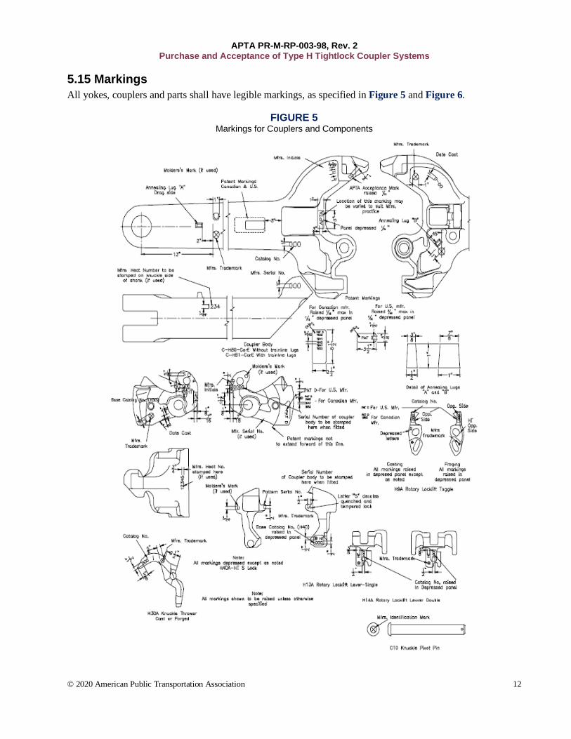
5.15 Markings All yokes, couplers and parts shall have legible markings, as specified in Figure 5 and Figure 6.
FIGURE 5 Markings for Couplers and Components

APTA PR-M-RP-003-98, Rev. 2 Purchase and Acceptance of Type H Tightlock Coupler Systems
© 2020 American Public Transportation Association 13
FIGURE 6 Markings for Yokes and Attachments

APTA PR-M-RP-003-98, Rev. 2 Purchase and Acceptance of Type H Tightlock Coupler Systems
© 2020 American Public Transportation Association 14
5.16 Purchaser’s inspection If the purchaser wishes to perform a predelivery inspection, it should be performed as per AAR Specification M-211. Inspectors should reference AAR Specification M-211 for additional information.
FIGURE 7 Type H Tightlock Coupler Rotary Operating for Passenger Cars and Locomotives, CH81E
Alternative Standard Adopted, 1937; Revised 1939; Tentative Standard Adopted, 1944; Advanced to Standard, 1946; Revised 1949, 1960, 1966; Standard S-166-80, Adopted, 1980
APTA PR-M-RP-003-98, Rev. 2 Purchase and Acceptance of Type H Tightlock Coupler Systems
© 2020 American Public Transportation Association 15
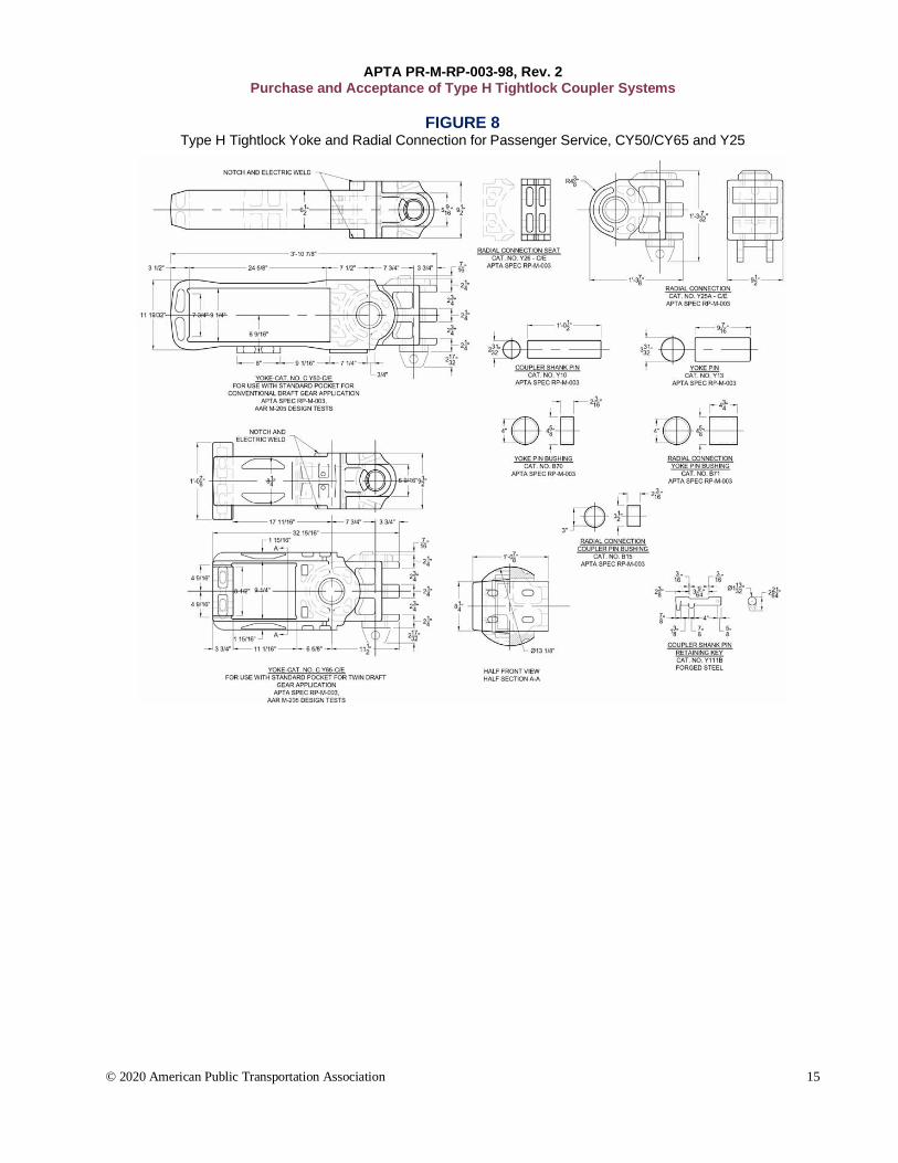
FIGURE 8 Type H Tightlock Yoke and Radial Connection for Passenger Service, CY50/CY65 and Y25

APTA PR-M-RP-003-98, Rev. 2 Purchase and Acceptance of Type H Tightlock Coupler Systems
© 2020 American Public Transportation Association 16
FIGURE 9 Type H Tightlock Coupler for Passenger Service, H5401E

APTA PR-M-RP-003-98, Rev. 2 Purchase and Acceptance of Type H Tightlock Coupler Systems
© 2020 American Public Transportation Association 17
FIGURE 10 Type H Tightlock Coupler for Passenger Service, H7308E

APTA PR-M-RP-003-98, Rev. 2 Purchase and Acceptance of Type H Tightlock Coupler Systems
© 2020 American Public Transportation Association 18
References This standard shall be used in conjunction with the following publications. When the following standards are superseded by an approved revision, the revision shall apply.
49 CFR Part 238, Passenger Equipment Safety Standards
Association of American Railroads: AAR Specifications M-201, Steel Castings AAR Specifications M-205 Coupler Yokes AAR Specifications M-211, Purchase and Acceptance of AAR Approved Couplers and Coupler Yokes
for Freight Service AAR Specifications M-1003, Specification for Quality Assurance
Abbreviations and acronyms AAR Association of American Railroads AISI American Iron and Steel Institute CFR Code of Federal Regulations CID Component Identification NATSA North American Transportation Services Association
Summary of document changes Title changed to “Purchase and Acceptance of Type H Tightlock Coupler Systems” Document formatted to the new APTA standard format. Sections have been moved and renumbered. “Summary” and “Scope and purpose” moved to the front page. Definitions, abbreviations and acronyms moved to the rear of the document. Two new sections added: “Summary of document changes” and “Document history.” Some global changes to section headings and numberings resulted when sections dealing with
references and acronyms were moved to the end of the document, along with other changes, such as capitalization, punctuation, spelling, grammar and general flow of text.
Participants updated. Figures moved from the end of the document and placed into document body near first reference to
each figure. Gage descriptions and figures revised to clarify usage and application procedures. “Scope and purpose”: Historical industry adoption dates moved to “Introduction.” Section 1.1: Although the AAR specification applies to freight equipment only, this standard applies
the listed requirements to APTA coupler system components. Section 1.2: Added: Standard Type H Tightlock Coupler requirements. Section 1.3: Added 100,000 lb vertical shear strength requirement. Added nonstandard coupler design
process details. Section 2.1: Added Grade C phase-out provisions. Section 2.2: Added Grade C phase-out provisions. Section 2.3: Revised certification requirements. Section 3: Removed “as applicable, except as identified in 3.2 Knuckles and Locks.” Section 5.1: Added “Items will be grouped in inspection lots of 12 pieces or fewer ordered. One item
will be inspected to represent the lot. If a failure is found in the lot, then all items in the lot must be inspected. Failures, however, do not prohibit the manufacturer from repairing and reinspecting after adjustment.”
Section 5.3: Added AAR M-211 as part of control for casting integrity.

APTA PR-M-RP-003-98, Rev. 2 Purchase and Acceptance of Type H Tightlock Coupler Systems
© 2020 American Public Transportation Association 19
Added new Section 5.4, “Wall thickness”: Wall thickness tolerances are defined per AAR M-211 Section 11.1. Uniform shank wall thickness shall be verified on a periodic basis via ultrasonic inspection or saw cut to verify core placement control.
Section 5.5.4: Removed Grade C requirements. Updated Grade E requirements to reflect current standards.
Table 2: Added standard products H7308, H5401 and BS-15. Section 5.10: Added language to direct inquiries to the contact on the landing page for this
recommend practice. Added that all coupler assemblies must be checked to conform to 31727–Inspector’s contour, 31701–Drawbar pulling lug and pin protector, 31703–Drawbar front face checking pin, 31706–Drawbar aligning wing face, and 31707–Drawbar face and contour. Clarified differences between Class I and Class II Inspector’s Gages. Updated gage tables. Removed Table 8 due to irrelevancy.
Section 5.12: Added “All machined corners must have a sufficient blended radius to reduce sharp edges and stress risers. Transitions between machined surfaces and cast surfaces must be blended.”
Section 5.12.4: Added graphite. Section 5.15: Added H5401E (Figure 9) and H7308E (Figure 10). Section 5.16: Added new section on purchaser’s inspection.
Document history
Document Version
Working Group Vote
Public Comment/ Technical Oversight
Rail CEO Approval
Policy & Planning Approval
Publish Date
First published — — — Jan. 22, 1998 March 17, 1999
First revision — — — — Feb. 13, 2004
Second revision Mar. 30, 2020 Jun. 8, 2020 Jun. 22, 2020 Aug. 31, 2020 Sept. 17, 2020
This document was retitled to “Purchase and Acceptance of Type H Tightlock Coupler Systems” from “Purchase and Acceptance of Type H Tightlock Couplers” as part of Rev. 2. For all previous publications of this document prior to Rev. 2, unless otherwise indicated, this document was titled “Purchase and Acceptance of Type H Tightlock Couplers.”

APTA PR-M-RP-003-98, Rev. 2 Purchase and Acceptance of Type H Tightlock Coupler Systems
© 2020 American Public Transportation Association 20
Appendix A (informative): Approval requirements for special design couplers, coupler parts, yokes and draft gear followers Special and proprietary designs that deviate from APTA catalog numbered items that are to be used in interchange or common carrier service by arrangement will require separate approval by the APTA Coupler and Draft Gear Committee if they are to be identified with the initials “APTA” either stamped or cast in raised letters.
Approval application content 1. Description of the special feature:
a. Function b. Component design type to which feature is applicable. c. Owner, builder or designer who developed.
2. Railroad(s), car owner(s) or manufacturer(s) requesting special design.
3. Car type for which special design is to be furnished on original application.
4. Replacement(s) (what can be applied). If not interchangeable with an APTA standard, design deviations are to be listed.
5. Include statement that the item will be manufactured, sampled, tested and inspected in accordance with, and will be equal to or better than, the requirements of applicable specifications. In the event that material deviated from APTA specifications, mechanical, chemical and hardenability, test reports must accompany the application, and a certification must be included that contains a statement that the component is compatible with APTA requirements. In addition, a certification must be included that the design complies with APTA operational and DOT safety requirements.
6. Specifications for reconditioning the special design, if different from applicable APTA specifications, must be provided to each purchaser on request.
Documentation requirements Twelve drawings listing material, heat treatment and complete dimensioning, and the name of the foundry or foundries that produce the item, must accompany the application.