
Pumps for the Production of Renewable Energy - Flowserve · Pumps for the Production of Renewable...
28
Technical Bulletin Pumps for the Production of Renewable Energy Experience In Motion
Transcript of Pumps for the Production of Renewable Energy - Flowserve · Pumps for the Production of Renewable...
Technical Bulletin
Pumps for the Production of Renewable Energy
Experience In Motion

Renewable EnergyTable of Contents and Figures
Figures PageFigure 1 Annual Energy Demand ................................................. 1Figure 2 Simplified Fossil Fuel Power Generation Flow Diagram ......... 2Figure 3 Global Solar Power Map ................................................ 3Figure 4 Simplified Parabolic Trough Flow Diagram .................... 4Figure 5 Simplified Power Tower Flow Design ............................. 5Figure 6 Parabolic Trough Solar Field, Storage and Steam Cycle .... 6Figure 7 Power Tower Solar Field, Storage and Steam Cycle ...... 7Figure 8 Typical Flashed-Steam Power Plant ............................... 8Figure 9 Dry-Steam Power Plant ............................................... 10Figure 10 Flashed-Steam Power Plant ......................................... 10Figure 11 Binary-Cycle Power Plant ............................................ 11Figure 12 Gasification Process Flow Diagram ............................. 14Figure 13 Pressure-Retarded Osmosis ........................................ 15Figure 14 Open-Cycle OTEC ......................................................... 16Figure 15 Natural Ocean Thermal Gradients ................................ 17Figure 16 Closed-Cycle OTEC ...................................................... 17Figure 17 Hybrid-Cycle OTEC ...................................................... 17Figure 18 Worldwide Wind Energy Resource
Distribution Estimates .................................................. 18Figure 19 Simplified Offshore Wind Farm Installation ................. 19Figure 20 Conventional Steam Fired Fossil Fuel Plant ................. 20
Pumps for the Production of Renewable Energy
Table of Contents PageIntroduction
................................................................................................. 1
Concentrated Solar Power (CSP) The Technologies ...................................................................... 4The Projects ............................................................................. 6
GeothermalTypes of Geothermal Power Plants ......................................... 10
Biomass Power Combustion ............................................................................ 13
Ocean PowerCurrent Status ........................................................................ 16Types of OTEC Power Plants .................................................. 17
Offshore Wind Power ............................................................................................... 18
Flowserve Pump RecommendationsBoiler Feed Water Pumps ....................................................... 21Circulating Water Pumps ........................................................ 22Condensate Extraction, Ammonia Recirculation
and Heat Transfer Pumps ............................................... 23Auxiliary Services Pumps ....................................................... 24Azimuthing Thrusters for Offshore Applications ..................... 25

1
Renewable EnergyIntroduction
Introduction
The market for energy is huge. “The Economist” magazine reports the world’s population currently consumes about 15 terawatts of energy annually. (A terawatt is 1000 gigawatts and a gigawatt is the capacity of the very largest of coal-fired power stations. A typical coal-fired power station generates 600 megawatts.) By 2030, global power consumption will likely rise to 30 terawatts (Figure 1).
Rising DemandDriven largely by economic growth in developing countries, global energy demand is expected to surge more than one-third by 2030 – and that’s assuming governments increasingly adopt policies to encourage energy efficiency. Fossil fuel will continue to make up most of the mix.
Economics, energy security and environmental concerns are driving a global quest for clean, renewable energy sources. While wind turbines make up a large share of these sources, they require no pumps. Four renewable energy sources of particular interest to Flowserve are:
•Biomass (including biogas)•Geothermal•Concentrated Solar Power (CSP)•Ocean Thermal Energy Conversion (OTEC)
All four share general characteristics. Each uses heat to turn turbines to produce electricity. All produce relatively small amounts of energy – about 50 mW per station – although larger installations do exist. And all must be subsidized to be economically feasible.
The technologies applied in geothermal (i.e., dry steam power, flashed steam power and binary-cycle power) and biomass
(i.e., thermochemical and anaerobic digestion and fermentation) are proven and reliable. On the other hand, CSP (i.e., trough-electric and power tower systems) is only now going into commercialization. Nevertheless, CSP is gaining momentum as feasible generating capacity has significantly increased along with the capability to store solar energy for use during periods of limited or no sunshine. OTEC is in its early stages of development.
At this point, biomass produces more energy globally than any other alternative source. It is expected to enjoy accelerated growth as forest and agricultural residues along with municipal solid waste become fuel rather than landfill material.
The potential of geothermal is enormous. The U.S. Department of Energy estimates global geothermal capacity of 50 000 times greater than all of the world’s oil and gas reserves. Iceland is exploiting this clean, renewable energy resource as it supplies approximately 55% of the country’s primary energy needs.
If successful, CSP will make commercial scale energy generation feasible. It is being deployed in California. Spain, Mexico, Australia and South Africa are moving ahead boldly. North Africa and Israel are in the exploratory stage.
One final word on renewable energy concerns ocean power or “wave power” as it is commonly known. To date, most of the attention has been focused on the potential of waves, tides and currents to generate electricity. Another ocean technology is rapidly gaining attention: ocean thermal energy conversion (OTEC). And, in fact, it may hold the most near-term commercial promise. A consortium is building a demonstration OTEC unit with a 10 mW capacity. Participation as an equipment supplier in these early stages of development is viewed as essential.
Note: While global energy demand is expected to grow by more than one-third, sources of renewable energy are projected to increase nearly fivefold.
Totals are in metric tons of oil equivalent
Oil 35.2%
Coal 24.8%
Natural Gas 20.5%
Biomass &Waste 10.5%
Oil 32.2%
Coal 22.8%
Natural Gas 21.9%
Biomass &Waste 11.1%
Nuclear 6.4%
Hydro 2.2%
Other Renewables 0.5%
Nuclear 6.9%
Hydro 2.7%
Other Renewables 2.4%
2004
Total: 11.20 billion tons Total: 15.41 billion tons
2030
Figure 1 – Annual Energy Demand By Type in 2004 and 2030 (projected)Source: International Energy Agency’s (IEA) World Energy Outlook 2006

2
Nevertheless, there are outstanding pump applications opportunities which Flowserve can exploit. For example, geothermal requires extraction of super-heated water from far below the earth’s crust. Then the return water requires treatment and deep well injection. CSP requires pump and seal systems to handle molten salts and synthetic oils at elevated temperatures. It also requires heat transfer pumps operating at high flow ranges, perhaps beyond that of existing, cost-efficient process pumps. OTEC requires the pumping of huge amounts of erosive (sand) and corrosive (HCl) salt water from depths of 1000 m (3300 ft) along with heat transfer and desalination applications.
With its vast experience in power generation and applications know-how, Flowserve has the opportunity to serve the renewable energy market identified previously.
Flowserve InterfaceAt first glance, renewable energy generation should be a prime market and target for Flowserve. Biomass, geothermal and CSP all utilize heat to generate electricity. Flowserve excels at traditional power plant services such as boiler feed water, condensate, water and treatment services, auxiliaries, etc.
There are, however, obstacles to overcome. At the top of the list, perhaps, is scale of plant. Flowserve’s traditional power market has been 450 mW power stations and larger. Yet, it does have considerable experience in industrial scale power house installations which are similar in size and scope to renewable energy installations. Developing right-size products at competitive prices will be a challenge. Segmenting the market by size of installation will be critical to marketing and sales strategies.
Renewable EnergyIntroduction
Figure 2 – Simplified Fossil Fuel Power Generation Flow Diagram
Renewable EnergySection 1: Concentrated Solar Power (CSP)
3
Section 1: Concentrated Solar Power (CSP)
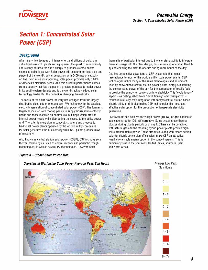
BackgroundAfter nearly five decades of intense effort and billions of dollars in subsidized research, plants and equipment, the quest to economically and reliably harness the sun’s energy to produce electric power seems as quixotic as ever. Solar power still accounts for less than one percent of the world’s power generation with 5400 mW of capacity on line. Even more disappointing, solar power provides only 0.01% of America's electricity needs. And this dreadful performance comes from a country that has the planet’s greatest potential for solar power in its southwestern deserts and is the world’s acknowledged solar technology leader. But the outlook is changing dramatically.
The focus of the solar power industry has changed from the largely distributive electricity of photovoltaic (PV) technology to the baseload electricity generation of concentrated solar power (CSP). The former is largely associated with rooftop panels to supply household electricity needs and those installed on commercial buildings which provide internal power needs while distributing the excess to the utility power grid. The latter is more akin in concept, structure and process to traditional power plants operated by the world’s utility companies. PV solar generates kWs of electricity while CSP plants produce mWs of electricity.
Also known as central station solar power (CSSP), CSP includes solar thermal technologies, such as central receiver and parabolic trough technologies, as well as several PV technologies. However, solar
thermal is of particular interest due to the energizing ability to integrate thermal storage into the plant design, thus improving operating flexibil-ity and enabling the plant to operate during more hours of the day.
One key competitive advantage of CSP systems is their close resemblance to most of the world’s utility-scale power plants. CSP technologies utilize many of the same technologies and equipment used by conventional central station power plants, simply substituting the concentrated power of the sun for the combustion of fossils fuels to provide the energy for conversion into electricity. This “evolutionary” aspect – as distinguished from “revolutionary” and “dissipative” – results in relatively easy integration into today’s central station-based electric utility grid. It also makes CSP technologies the most cost-effective solar option for the production of large-scale electricity generation.
CSP systems can be sized for village power (10 kW) or grid-connected applications (up to 100 mW currently). Some systems use thermal storage during cloudy periods or at night. Others can be combined with natural gas and the resulting hybrid power plants provide high-value, transmittable power. These attributes, along with record setting solar-to-electric conversion efficiencies, make CSP an attractive, feasible renewable energy option in the sunbelt regions. This is particularly true in the southwest United States, southern Spain and North Africa.
Figure 3 – Global Solar Power Map
Overview of Worldwide Solar Power Average Peak Sun Hours
0 - 1
Average Low Peak Sun Hours
1 - 2
2 - 3
3 - 4
4 - 5
5 - 6
6 - 7+

Renewable EnergySection 1: Concentrated Solar Power (CSP)
4
The TechnologiesFour CSP technologies are currently in deployment and evaluation.
•Parabolic trough – Without storage or hybrid fossil – With storage – With hybrid fossil
•Parabolic dish/engine•Power tower•CPV
A brief description of each follows.
Parabolic TroughA collector field comprises many troughs in parallel rows aligned in a north-south axis. This configuration enables the single-axis troughs to track the sun from east to west during the day to ensure that the sun is continuously focused on the receiver pipes. Individual trough systems currently can generate about 80 mW of electricity.
Trough designs can incorporate thermal storage – setting aside the heat transfer fluid in its hot phase – allowing for electricity generation several hours into the evening. Currently, all parabolic trough plants are hybrids, meaning they use fossil fuel to supplement the solar output during periods of low solar radiation. Typically, a natural gas-fired heat or a gas steam boiler/reheater is used. Troughs can also be integrated with existing coal-fired plants.
Solar FIeld
CondenserSteam Generator
Hot SaltTank
Cold SaltTank
SteamTurbine Electrical
Generator
Figure 4 – Simplified Parabolic Trough Flow Diagram

Renewable EnergySection 1: Concentrated Solar Power (CSP)
5
Figure 5 – Simplified Power Tower Flow Design
Dish/EngineThis system uses a parabolic reflector to focus sunlight onto a receiver located at the focal point of the dish. The sunlight heats a working fluid, which transfers the heat to a small engine used to generate electricity. The most commonly used type of heat engine found in dish/engine systems is the Sterling engine. Modular in nature with single units producing power in the range of 10 kW to 35 kW, dish/engine systems are best suited for distributed or remote generation applications. They can be sited at large plants by aggregating many units. Note, however, that these systems have NO PUMP APPLICATIONS.
Steam Storage System
Condenser0.06 bar, 50°C
(0.90 psi, 125°F)Heliostat Field
Solar Receiver Steam Drum
Steam 40 bar, 250°C
(580 psi, 485°F) SteamTurbine Generator
11.0 MWe
There are no operating commercial dish/engine power plants. However, Sterling Engine, the technology’s developer, has test deployments with Sundia National Laboratories in Albuquerque, New Mexico. Sterling also has contracts with southern California utilities to provide as much as 1800 mW of solar generated electricity. Other planned dish/Sterling deployments include Eskom, South Africa, and one each in Spain, France and Italy through Schlaich Bergermann.
Power TowerThis technology utilizes many large, sun-tracking mirrors (i.e., heliostats) to focus sunlight on a receiver at the top of a tower. A heat transfer fluid heated in the receiver is used to generate steam, which in turn is used in a conventional turbine-generator to produce electricity. Currently there are two designs used. The first uses water in the form of steam as the heat transfer fluid (BrightSource Energy and eSolar); the second uses molten salt because of its superior heat transfer and energy storage capabilities. Individual commercial plants are being sized to produce from 50 mW to 200 mW of electricity.
Worldwide interest in power towers has been on the increase. An international consortium led by Bechtel and Boeing has been formed to commercialize power tower technology globally. In addition to the U.S.A., Spain is a hotbed of activity with at least two projects under way. Egypt, Morocco and Italy are in the planning stages while Israel has become enthusiastic about the technology.
CPVConcentrating PV systems use concentrating optics or lenses that gather sunlight and concentrate its intensity onto small PV cells, minimizing the amount of material needed. Four PV technologies are available. They are:
• Fixed, flat-plate with crystalline silicon• Fixed, flat-plate with thin film•One-axis tracking, flat-plate with crystalline silicon•Two-axis tracking concentrating PV
The last of these, CPV, has been proven to provide higher conversion efficiencies than conventional flat-plate systems; it has yet to gain a commercial foothold. Although over 10 gW of PV is deployed worldwide, the largest PV plants are just over 20 mW. Like dish/engine systems, PV technology may be most suitable for distributed or remote generation applications. Like dish/engine, however, there are NO PUMP APPLICATIONS.

Renewable EnergySection 1: Concentrated Solar Power (CSP)
6
•Andasol (Marquesado del Zanete, Spain). This 50 mW parabolic trough plant was developed and constructed by ACS Cobra Group (Spain) and Solar Millenium Group (Germany).
•Solar Tres (Ecija, Spain). This is a 15 mW demonstration power tower plant with molten salt storage. The lead contractor is Sener (Spain) with other Spanish, French (Compagnie de Saint-Gobain) and German (Siemens) partners
•Nevada Solar One (Mojave Desert, California). This is a 64 mW parabolic trough plant built by Acciona and Solargenix Energy, both of the USA. Schott and Flabeg (both of Germany) supplied the main components of the collection system while Siemens provided the two-stage steam turbine.
* As of August 2008. More than 80 active projects for Spain have been identified with an approximate size of 50 mW each. In the United States, seven major projects with an average capacity of 250 mW each have been identified.
The ProjectsThis is not intended to be a comprehensive or exhaustive list of CSP projects currently underway. It will, however, demonstrate the level of serious interest in and commitment to the commercialization of CSP technology, specifically parabolic trough and power tower.
The United States and Spain are the undisputed leaders in deploying CSP technology. Each has more than 50 projects in some stage of development. Mexico, Australia and South Africa have active projects. Morocco, Algeria and Israel are currently evaluating projects. The EU is discussing plans to invest 400 billion euros in plants across North Africa and the Middle East to satisfy European needs. It has been estimated by the IEA that about U.S. $42 billion will be invested in solar thermal power between 2005-2020.
•PS 10 (Sanlucor, Spain). World’s first CSP plant based upon tower and heliostat field technology. The 11 mW plant is a project of Solucar Energia (Abengoa).
Types of CSP Power PlantsAs the various CSP technologies continue to evolve, it is becoming apparent that two – parabolic trough and power tower – have the best chance for large-scale (i.e., > 50 mW) central station applications. As trough and power tower systems collect heat to drive central turbine-generators, they are best suited for relatively
ColdTank
HotTank
SteamTurbine Electrical
Generator
HTFGas
Heater
SOLAR FIELD THERMAL STORAGE POWER BLOCK
Deaerator
Expansion Vessel
Condenser
Low-PressurePreheater
Solar SteamGenerator
Solar Super-Heater
Solar Preheater
Solar Reheater
Feed Water Pump
HTF Pump
Salt HTF Heat Exchanger
Cold Pipe Heater
Hot Pipe Heater
large plants. This plus the balance of plant equipment gives both systems a cost advantage of economy of scale. Additionally, thermal storage and/or the use of hybrid fossil fuel gives them an overwhelming advantage in system reliability and power generating availability.
Figure 6 – Parabolic Trough Solar Field, Storage and Steam Cycle Operation

Renewable EnergySection 1: Concentrated Solar Power (CSP)
7
to 400°C (750°F). A steam generator produces superheated steam to power a conventional two-stage industrial steam turbine with reheat, which generates the electrical power. A conventional cooling tower rejects heat from the condenser using cooling water.
Alternatively, in more conventional boiler power generation, the heat transfer fluid is pumped through a heat exchanger. Here it releases its heat to increase the temperature of the boiler feed water to create the steam for power generation. In parabolic trough systems, boilers are typically fired by natural gas when sunlight is inadequate.
Parabolic TroughA solar collector field contains many parallel rows of troughs connected in series. Rows are typically placed on a north-south axis, allowing the single-axis troughs to track the sun from east to west during the day. The parabolic curved, trough-shaped reflectors concentrate the sun’s energy onto a receiver pipe or heat collection element. In the case of the Nevada Solar One installation, there are 219 000 parabolically shaped mirrors focusing 30 to 60 times the sun’s energy onto 19 000 receiver tubes.
Synthetic oil serves as the heat transfer fluid and circulates in a closed loop through the receiver tubes which can handle media up
Heliostat Field
Receiver Cold Salt Storage Tank
SteamGenerator
CondenserTurbineGenerator
Substation
Hot Salt Storage Tank
290° C
565° CSalt
Salt
Figure 7 – Power Tower Solar Field, Storage and Steam Cycle Operation
Power TowerA significant advantage of power tower plants is that molten salt can be heated to 565°C (1050°F) with steam generation at 538°C (1000°F), which is utility standard main temperature. This results in a somewhat higher cycle efficiency than is achievable using the lower temperature (about 390°C [735°F]) steam achievable with a trough system. Furthermore, power towers have the advantage that molten salt is used both as the heat transfer fluid and as the storage medium. By comparison, the parabolic trough system uses a high-temperature oil as the heat transfer fluid, and requires oil-to-salt and salt-back-to-oil heat exchange for thermal storage. The result is that storage is less costly and more efficient for power towers than for parabolic troughs.
A power tower uses thousands of sun-tracking mirrors called heliostats to redirect the sun’s energy to a receiver at the top of a tower. The Solar Tres 15 mW installation at Ecija, Spain, for example, employs 285 200 m2 (3 068 750 ft2) of heliostat surface and a tower approximately 120 m (400 ft) tall.
The solar energy heats a molten salts solution which is pumped to the 120 mW thermal high-efficiency receiver at the top of the tower. The molten salts solution is then transferred to a large thermal stor-age system with insulated immersion heaters. Storage temperature is at 565°C (1050°F). The solution is pumped to a steam generator where it produces steam to drive the turbine and generate electricity.
Pump applications include typical main cooling and condensate services. There are solar pre-warmer feed water pumps, thermal fluid and melted salts heat exchanger pumps, heat transfer and molten salt pumps plus auxiliaries.
Pumps for CSP Power GenerationSee Section 6: Flowserve Pump Recommendations.

Renewable EnergySection 2: Geothermal
8
or steam into a power plant for electricity production. The type of power plant depends upon a reservoir’s temperature, pressure and fluid content.
Geothermal energy is especially attractive because it makes electricity around the clock, unlike wind or solar power that requires backup sources of generation. Also, unlike wind and solar installations, geothermal plants have a small footprint – smaller, even, than many fossil-fueled power plants.
Today, there is about 8000 mW of installed geothermal capacity worldwide, with 3000 mW in the U.S., the top producer. The biggest developed field in the U.S. is 72 miles north of San Francisco at the Geysers. Owned by Calpine, it generates 725 mW of electricity, the equivalent of one-and-a half large conventional power plants.
There are 62 operating geothermal power plants in California, Nevada, Utah, Hawaii and Alaska which produce 3.0% of the nation’s renewable energy and produces 0.3% of all U.S. power. Seventy-five projects are under development in 12 Western states, which would nearly double current capacity to more than 5800 mW over the next three to five years.
Section 2: Geothermal
BackgroundInterest in geothermal is heating up... literally. Geothermal energy – tapping heat deep in the earth to generate power – may have more potential with less impact to society than any of the other alternative resources. A 2007 study on geothermal energy, produced by an interdisciplinary team at the Massachusetts Institute of Technology, found that geothermal energy could produce 10% of the USA’s energy by 2050 at prices that would be competitive with fossil fuels.
Geothermal energy’s supporters claim it is:
•Reliable – available 24 hours regardless of changing weather•Renewable – sustainable because of the heat from the earth•Minimal air emissions – compared with fossil fuels
Electricity production using geothermal energy is based on conventional steam and generator equipment, in which expanding steam powers the turbine/generator to produce electricity. There is no combustion and, thus, minimal emissions. Geothermal energy is tapped by drilling wells into the reservoirs and piping the hot water
Production Well
Brine
Waste Brine Direct Heat Uses
SteamWater
Water
Steam
Steam
Injection WellGeothermal Zone
GeneratorTurbine
Cooling Tower
Air and Water Vapor
AirAir
Figure 8 – Typical Flashed-Steam Power Plant

Renewable EnergySection 2: Geothermal
9
Geothermal Processes ExplainedBecause electricity production using geothermal energy is based on conventional steam turbine and generator equipment, in which expanding steam powers the turbine/generator to produce electricity, it is combustion free. It emits only steam. Thus, it is intrinsically environmentally friendly.
Geothermal energy is tapped by drilling wells into the earth’s reservoirs and piping the hot water or steam into a power plant for electricity production. The type of power plant depends upon a reservoir’s temperature, pressure and fluid content.
Before reviewing the types of geothermal power plants, a little more background regarding underground heat is required. It is hard to imagine, but the center of the earth is nearly as hot as the surface of the sun. In fact, the earth’s crust stores some 5 billion exajoules of heat energy. According to EV World magazine, just 0.1% of that could power the entire planet for over 13 000 years.
In volcanic areas around the world, such as the western USA (including Hawaii), the Philippines, Indonesia, New Zealand, Iceland and many other countries, it is possible to exploit that potential by drilling wells that enable heated water trapped underground to be brought to the surface and used directly for producing electricity. The geysers and hot springs of California and Hawaii are excellent examples of volcanic geothermal energy sources. Typically, volcanic water reaches and exceeds temperatures over 300°C (570°).
If there is no natural volcanism available to bring this heat to the surface, the answer is to create controlled, artificial volcanism – what is known as engineered geothermal systems (EGS). Instead of relying on natural hot springs, you make your own.
Two parallel holes are drilled in the ground a few hundred meters apart. Drilling is continued until the down-hole rock is approximately 200°C (390°F). Then cold water is pumped down one hole, absorbs the required heat and is pumped back up the other hole at a suitably elevated temperature. Since the temperature of this geothermal brine is relatively low, it is pumped through a heat exchanger where its energy is transferred to a working fluid (e.g., isopentane). A suitable working fluid will vaporize at lower temperatures and higher pressures than water, making it ideal for recovering energy from low-temperature geothermal fluids. The geothermal fluid is then returned to the reservoir to be reheated.
EGSs are also known as binary cycle power plants.
Current StatusAccording to the International Energy Association (IEA) and the Geothermal Energy Association (GEA), geothermal accounts for 0.03% of all global energy production and 0.35% of all renewable energy production. Of all renewable energy, geothermal output trails only biomass and hydroelectricity. It is far ahead of solar and wind power and much more cost competitive with fossil fuels currently.
Both the IEA and GEA project that as much as 10% of the world’s electricity needs could be provided by geothermal by 2030. The catch: government policy and subsidy support are needed to make it happen.
Nevertheless, geothermal energy is a significant energy contributor today. Iceland satisfies more than 80% of its energy needs through renewables – of that, approximately 55% is geothermal and 17% is hydro. About a quarter of the electricity in the Philippines is derived from geothermal. By 2017 Kenya expects to cover 25% of its electricity needs through geothermal. In the USA it is projected that California and Nevada will derive about 10% and 15%, respectively, of their electricity requirements when current projects are completed by 2012.
Among the largest players in geothermal energy are:
•Chevron – the world’s largest producer of geothermal energy.•Glitnir (Reykjavik, Iceland) – active in Scandinavia, Russia,
USA, Canada.•Calpine (California, USA) – developed the “Geysers,” north of San
Francisco. This is the largest complex of geothermal power plants in the world, currently producing 750 mW of electricity. Another 80 mW of electricity will come on line in 2010.
•U.S. Geothermal (Nevada) – is commissioning phase one of Idaho's Raft River Geothermal Project, a 14 mW power plant.
•Geodynamics (Australia) – is developing the Cooper Basin in South Australia, which has the hottest non-volcanic rocks of any known place in the world.

Renewable EnergySection 2: Geothermal
10
Types of Geothermal Power Plants
Dry Steam Power Plant
Rock Layers
ProductionWell
InjectionWell
GeneratorTurbine
Load
Flash Steam Power Plant
Rock Layers
Generator
FlashTank Turbine
Load
ProductionWell
InjectionWell
Dry-Steam Power PlantsDry-steam power plants draw from underground reservoirs of steam (>300°C [570°F]). The steam is piped directly from wells to the power plant, where it enters a turbine. The steam turns the turbine, which turns a generator. The steam is then condensed and injected back into the reservoir via another well. The Geysers in northern California, the world’s largest single source of geothermal power, uses dry steam.
First used in Italy in 1904, dry steam is still very effective.
Flashed-Steam Power PlantsFlashed-steam is the most common type of geothermal power plant. This type plant taps into reservoirs of water with temperature greater than 182°C (360°F). This very hot water flows up through wells under its own pressure. As it flows to the surface, the fluid pressure decreases and some of the hot water boils or “flashes” into steam. The steam is then separated from the water and used to power a turbine/generator unit. The remaining water and condensed steam are injected through a well back into the reservoir.
Figure 10 – Flashed-Steam Power Plant
Figure 9 – Dry-Steam Power Plant

Renewable EnergySection 2: Geothermal
11
Binary Cycle Power Plant
Rock Layers
ProductionWell
InjectionWell
Heat Exchanger With Working Fluid
GeneratorTurbine
Load
Binary-Cycle Power PlantsThis type of plant is known as an engineered geothermal system (EGS). It operates at lower temperatures of about 107°C to 182°C (225°F to 360°F). These plants use heat from the geothermal water to boil a working (i.e., binary) fluid, usually an organic compound with a lower boiling point. The working fluid is vaporized in a heat exchanger and the vapor turns a turbine. The water is then injected back into the ground to be reheated. The water and the working fluid are confined in separate closed loops during the process, so there are little or no air emissions.
The binary-cycle power plant has been described as a typical, closed-loop Rankine cycle. This cycle is similar to those that generate about 80% of the world’s electric power, including virtually all solar, thermal, biomass, coal and nuclear power plants.
Figure 11 – Binary-Cycle Power Plant
General Notes
1. Regardless of plant type, geothermal power plants are relatively small, 15 mW to 50 mW output. Plant footprint is significantly smaller than that of fossil fuel plants.
2. In addition to electricity production, geothermal energy has other uses.
a) Hot water from geothermal resources can be used to provide heat for industrial processes, greenhouses, crop drying, heating buildings, etc. This is called “direct use.” It requires water pumped from a well and a mechanical system (i.e., pumps, heat exchangers and controls) to deliver the heat directly for its intended use.
b) Geothermal heat pumps transfer heat from a building to shallow ground during the cooling session, and transfer heat from the ground into a building during the heating season.
c) Pumps for Geothermal Energy Generation See Section 6: Flowserve Pump Recommendations
3. Geothermal power plants can meet the most stringent clean air standards. They emit little carbon dioxide, very low amounts of sulfur dioxide and no nitrogen oxides.
4. Although many geothermal plants produce no appreciable solid waste, the unique characteristics of some geothermal fluids require special attention to handle entrained by-products. These solid by-products often contain valuable minerals that can be recovered and recycled for other industrial uses.
In some cases, mineralized geothermal brine contains enough corrosive salts and heavy metals to require special disposal. To remove the heavy metals, the plants treat and dewater the waste stream. The salts are crystallized and removed. The remaining solids contain mostly silica, which is removed for use in several industrial processes.
Pumps for GeothermalSee Section 6: Flowserve Pump Recommendations.

Renewable EnergySection 3: Biomass Power
12
and for sale to public utilities. Over the next five years, Waste Management Inc. (a subsidiary of Wheelabrator Technologies, Inc.) expects to generate 700 mW of electricity (roughly equivalent to a modern coal-fired plant) which it plans to sell to industrial users and utilities. This energy will be produced by capturing methane gas from its landfills.
The landscape, however, is changing as larger utilities and energy companies are entering the biopower arena. Penergy Power (London) will open a 350 mW wood chip-fuel power plant in Port Talbot, Wales, in 2010. Renewable energy giant Abengoa (Spain) is building a string of biomass gasification plants in the U.S. GE Energy, Schmack Biogas AG (Germany) and many other prominent electric power corporations are committed to biopower.
Processes and FeedstocksBiomass-based energy systems can use a large variety of feedstock, including waste. They can use many conversion technologies to produce: energy; solid, liquid or gaseous fuels; and other valuable materials.
The European Biomass Industry Association (EUBIA) groups the various methods of biomass conversion into four basic categories:
•Direct combustion•Thermochemical conversion processes
(including pyrolysis and gasification)•Biochemical processes
(including anaerobic digestion and fermentation)•Physiochemical processing (including extraction and esterification)
This section will focus on direct combustion and thermochemical processes as these traditional methods of producing heat, fuel gas and bio oil are by far the largest contributors to electricity generation. It may also be worth noting here that there appears to be a growing trend to replace coal boilers with state-of-the-art fluidized-bed wood-burning boilers. This will be further explained in the following section: Types of Biomass Power Plants.
Biomass feedstock includes tree, arable crop, algae and other plant, agricultural and forest residues, effluents, sewage sludge, manure, industrial by-products and the organic fraction of municipal solid waste.
Section 3: Biomass Power
BackgroundFacing rising energy prices and growing concerns about global warming, governments and business are trying to turn trash into treasure. They’re pursuing different “waste to energy” conversion technologies that generate power by burning everything from wood chips and banana peels to sewage sludge and tree trimmings. These efforts not only cut down on the use of fossil fuels, but also reduce the amount of solid waste consigned to landfills. There is another benefit of converting decaying organic waste into energy: reducing methane gas emissions, the potent greenhouse gas emitted by garbage dumps which is more environmentally harmful than CO2.
Although it does not get much public attention, biomass is the biggest source of renewable electricity in the U.S. and Europe today – producing more electricity than wind, solar and geothermal sources combined.
In broad terms, biomass refers to the conversion of plant matter into a transportation fuel (biofuels) or electricity (biopower), usually by incinerating waste material or creating combustible gas through a chemical process. A significant amount of electricity also is made by gathering and burning landfill gas. This section will focus on biopower.
Because biomass plants typically are small – usually less than 50 mW in capacity or one-tenth the size of a conventional fossil-fuel power plant – equipment costs are high relative to the amount of power produced. That, in turn, makes generating costs somewhat high – typically 5 to 12 cents a kW/h without subsidies. Costs can be expected to come down as technology improves and as more waste material gets redirected to electricity production, providing a cheap fuel stream.
Many experts believe biomass will expand dramatically in coming years as more industries look for ways to make electricity out of their waste, diverting more material from landfill sites.
Current StatusPresently, the U.S. and Europe generate about 5% of their electricity requirement from biomass. This is expected to grow to 8% by 2010 and to more than 11% by 2030. For all its hype, clean energy (i.e., wind, solar, geothermal, ocean) presently satisfies about 0.5% of the world’s energy needs. By 2030, the IEA projects these combined energy sources will satisfy about 2.4% of the world’s energy needs.
To date, the biggest biomass power generators have not been public utilities but forest-product companies with large sawmill and pulp operations. In the U.S., for example, International Paper, Weyerhauser and Georgia Pacific produce electricity for themselves

Renewable EnergySection 3: Biomass Power
13
CombustionConventional Steam Turbine Systems Except for differences in fuel handling and preparation and emission control, wood-fired steam turbine systems are essentially the same technology as that found in coal-fired plants. However, the lower density and heating value of wood relative to coal means that biomass systems require more combustion and heat transfer surface areas. The tradeoff between additional costs of fuel handling and extra boiler combustion area for wood and simpler emissions controls relative to coal translates into approximately the same costs for biomass system.
In a conventional biomass-fired combustion steam turbine, wood is first prepared (sized and possibly dried) then burned in a boiler to produce pressurized steam. The steam is expanded in a turbine to generate electricity. For power production, a fully condensing turbine is used. If process heat is to be produced in addition to electricity, a condensing-extraction (or back-pressure) turbine is used instead. In this cogeneration mode, some steam after producing electricity is taken from the turbine for process heat.
Specific boiler types used to generate steam include pile burners (dutch ovens), grate burners (stationary or traveling grate), suspension burners, and atmospheric fluidized-bed combustors (bubbling-bed or circulating-bed). These combustion methods will produce boiler efficiencies ranging from 65 to 75% with net plant efficiencies from 20 to 25%.
Fixed-bed combustion includes grate furnaces and underfeed stokers. With capacities up to 200 mW, grate furnaces are suitable for burning biomass with high moisture content. Primary air passes through a fixed bed where drying, gasification and charcoal combustion take place in consecutive stages. The combustion gases are burned in a separate combustion zone using secondary air. Underfeed stokers are limited to systems producing up to 6 mW.
Today, wood is the most commonly used solid biofuel. The raw material can be in the following forms: logs, stems, needles and leaves from the forest; bark sawdust and cuttings from the sawmill; chips and slabs from the wood industry; chips, black liquor and residues from pulp and paper plants; and recycled wood from demolition.
In most cases, wood waste is processed into forms that allow for easy transport, storage, and combustion such as chips, pellets, briquettes and powder.
Types of Biomass Power PlantsBiomass feedstock can be used for power generation in three general applications:
•Stand-alone, grid-connected biomass-based power plants•Cogeneration at agricultural and forestry processing facilities for
on-site heat and power needs with export of excess power to the local distribution grid (The industry terminology for this type of plant is CHP – combined heat and power)
•Co-firing at fossil-fired electric generation facilities
For each of these, the current technology of choice is the steam-turbine cycle, or Rankine cycle. For a variety of reasons, however, biomass-fired plants are smaller and less efficient then fossil-fuel plants. Wood contains about 50% moisture. This high moisture effectively reduces the heat value of a metric ton of wood to about one-third less than the heat value of a metric ton of coal. The high costs of handling, transporting and storing large quantities of biomass negates any economies of scale associated with building large power plants. As a result, biomass-based power plants are typically built to produce 50 mW of electricity versus 450 mW and larger fossil-fuel facilities.
Category Examples
Dedicated plantations
Short-rotation forest (eucalyptus, willow)
Perennial crops (miscanthus)
Arable crops (rapeseed, sugarcane, sugarbeet)
Residues
Wood from forestry thinning
Wood felling residues
Straw from cereals
Other residues from food and industrial crops (sugarcane, tea, coffee, rubber trees, oil and coconut palms)
By-products and wastes
Sawmill waste
Manure
Sewage sludge
Organic fraction of municipal waste
Used vegetable oils and fats
Source: EUBIA
Examples of Biomass Resources

Renewable EnergySection 3: Biomass Power
14
Co-firing biomass with coal in traditional coal-fire is becoming increasingly popular to reduce SO2 and NOx emissions. Additions of new fuel-handling equipment, modifications and improvements to the boilers and electrostatic precipitators are required to co-fire with coal. These changes, however, would likely be less costly than installing scrubbers, switching to low sulfur coal, or purchasing emission allowances. Because of the moisture present in wood, some derating of the boiler may occur.
Fluidized-bed combustion systems are suitable for large-scale appli-cations to 300 mW in size. In these designs, wood is injected into the combustion chamber through ports and burned in suspension. Air entering the boiler from below fluidizes a bed of hot, granular, inert material, usually silica sand and dolomite. The inert material heats the biomass quickly to ignition temperature, stores the thermal energy and provides the residence time for full combustion. (A good example of this system is found at Public Service of New Hampshire’s Schiller Station, a 50 mW fluidized-bed wood-burning boiler. Replacing a coal-fired boiler, it was sized to produce 450 000 pounds per hour of steam at 86 bar and 510°C (1250 psi and 950°F).
GasificationAlso known as gasifiers, this system breaks biomass down into combustible gases which are burned to heat high-pressure boilers. An example of this technology can be found at the University of South Carolina (Columbia, South Carolina) where a biomass heating system has replaced two of the campus’s fossil fuel boilers while providing its own electrical power.
Waste wood is turned into synthetic gas in a low-oxygen pyrolysis process. The gas is reformed at the top of the gasifier into a mixture of methane, hydrogen and carbon monoxide. The gas is fed into an oxidizing chamber where air is added to produce combustion. In effect, gases rather than wood are being burned which is a much cleaner process.
The combustion process raises the temperature of the gases to about 1040°C (1900°F). The hot gases are fed into a waste-heat boiler that generates steam at 41 bar at 23°C (600 psi at 74°F). The system can generate 60 000 pounds of steam per hour.
The gasifier produces steam at a higher pressure than is needed for the heating system. The extra pressure is used to turn a back-pressure turbine generator to produce electricity. The generators produce about 1.4 mW, enough to power the biomass facility and another energy facility.
In addition to the typical boiler feed and condensate pump applications, the gasifier system uses a reverse osmosis unit that treats the boiler feed water.
Pumps for Biomass Energy GenerationSee Section 6: Flowserve Pump Recommendations.
Three Gasifiers OxidationAir Ducting
Waste Heat Boiler
I.D. Fan
ElectrostaticPrecipitator
Stack
Oxidizer
GasificationAir Fan Economizer Steam Turbine Generator
Figure 12 – Gasification Process Flow Diagram

Renewable EnergySection 4: Ocean Power
15
• Tidal turbines are similar to wind farms. Tidal turbines are arranged underwater in rows.
• A similar device is the tidal fence which looks like giant turnstiles. Because seawater has a much higher density than air, ocean currents carry significantly more energy than air currents. (Note: saltwater is 850 times denser than air.)
Current PowerThe harnessing of ocean current power is still in its infancy despite its huge potential as an energy source. A handful of prototypes and demonstration units have been developed, including Hammerfest Strom’s submerged wind-like turbines that capture energy with hydrodynamic, rather than aerodynamic, lift or drag. A new and more promising concept is the open-center turbine being developed by Gulfstream Energy and OpenHydro.
Salinity Gradient Energy This concept exploits the salinity gradient – or salt differential – between seawater and freshwater to produce electricity. It has been described as the reverse osmosis process (used for desalination and water treatment) running backward and producing power from the flow of freshwater. Known as the pressure-retarded osmosis or PRO, it basically involves pumping seawater at 60% to 85% of the osmotic pressure against one side of semi-permeable membranes whose other side is exposed to freshwater. When freshwater compelled by osmosis flows across the membranes, it dilutes the seawater and increases its volume – and, consequently, the pressure within the saltwater chamber. A generator-driving turbine is spun to produce electricity.
In 2007, Statkraft (Norway) initiated construction of the world’s first osmotic plant prototype. It is located at Tofte on the Oslo fjord and will begin operation in late 2008. Energy Recovery (Oakland, CA) is also operating pilot plants.
Note1. While still in the earliest stages of development, osmotic ocean
power has significant potential as both sources of both electric power and freshwater for civilian populations. It also could develop into important business for Flowserve.
Section 4: Ocean Power
BackgroundThe new frontier of renewable energy is ocean power. Yet, ocean-energy technology is in its infancy, and significant hurdles to its widespread deployment remain. Among them are:
• Determining how to cost-effectively produce power on a large scale without harming marine life and impeding navigation.
• Negotiating a permitting process that companies contend is too lengthy, cumbersome and expensive.
Despite the hurdles, supporters believe there is an abundance of energy sitting off the world’s coastlines just waiting to be tapped. While the amount of energy currently being generated is miniscule, the Electric Power Research Institute – the research arm of U.S. utility companies – estimates that oceans could supply about 10% of the electricity consumed in the U.S. and other coastal countries.
There are several ways to harness ocean energy. These include:
• Mechanical – wave, tidal, current• Salinity gradient – pressure retarded osmosis (PRO)• Ocean thermal gradient – ocean thermal energy conversion (OTEC)
To date, the mechanical methods of generating electricity have achieved the most success and notoriety. A brief look at these variations may be helpful.
Wave PowerThe Pelamis wave energy converter is a snake-like device relying on vertical wave motion to move articulated joints in the body which then pump high-pressure oil through generator-driving hydraulic motors. It has been successfully employed at the world’s first wave farm in Aguacadoura, northern Portugal.
The buoy concept typically consists of modular buoy-arrays moved offshore. It converts the vertical component of waves’ kinetic energy into electricity by directing pressurized seawater through two-stroke hose pumps into a turbine-driven generator. Finerva Renewables, AWS Ocean Energy, Ocean Navitas, Iberdrola Renewables and others have successfully demonstrated commercial-scale systems.
Breakwater and shoreline technologies include oscillating water columns (Voith Siemens), floating barges (Wave Dragon Ltd.), the tapchan (or tapered channel system) and the pendulor device.
Tidal PowerThe most significant difference between wave and tidal energy is that waves occur in water closest to the surface, whereas the entire water body moves from surface to seabed in a tide. Tidal power technologies include the following:
• Barrage systems. The concept of building dams composed of gated sluices and low-head hydroturbines across channels to harness water level differentials has been proven productive by long-standing instal-lations like the Annapolis Station in the Bay of Fundy (Nova Scotia) and La Rance, France.
Membranes
Fresh WaterSupply Pump
Fresh Water Circulating Pump
SaltwaterSupply Pump
Saltwater Booster PumpEnergy Recovery Device Turbine Generator
Filter
Filter
Figure 13 – Pressure-Retarded Osmosis

Renewable EnergySection 4: Ocean Power
16
Current StatusOTECThe mechanical methods of marine energy conversion are largely proven and are in various stages of commercialization. Nevertheless, their impact on satisfying electric energy demand will be minimal. By their design, they are relatively small (i.e., by output measured in kWs and low mWs) and incapable of significant base load generation. On the other hand, ocean thermal energy conversion (OTEC) has the potential to make significant contributions of 10 mW and more to the grid per operating unit.
Xenesys, a Japanese firm, has been a leader in OTEC technology development. The Natural Energy Laboratory (a U.S. private partnership) and the National Renewable Energy Laboratory (NREL) are operating pilot plants in Hawaii. The government of India is testing a one mW plant.
A large, diversified American company is drawing up plans to build a 10 mW plant. The further development and commercialization of OTEC (and osmotic energy conversion) hold potentially immense value for Flowserve not only in terms of pump sales but also in thruster positioning systems for floating vessel installations.
A Brief HistoryOceans absorb and store tremendous amounts of solar energy. The technology for converting this solar radiation into electric power is OTEC, which exploits the ocean’s thermal gradients – temperature differences of 20°C (36°F) or more between warm surface waters and cold deep seawater – to drive a power- producing cycle.
Besides sourcing a clean, renewable reserve of energy, OTEC has the potential to provide many useful by-products such as freshwater, hydrogen via electrolytic processing of freshwater, and lithium and uranium, which may be extracted from deep seawater.
The first documented reference to the use of ocean temperature differences to produce electricity is found in Jules Verne’s “Twenty Thousand Leagues Under The Sea” published in 1870. Eleven years later, Jacques D’Arsonval proposed to use the relatively warm (24°C to 30°C [75°F to 86°F]) surface water of the tropical oceans to vaporize pressurized ammonia through a heat exchanger (i.e., evaporators) and use the resulting vapor to drive a turbine-generator. The cold ocean water transported to the surface from 800 m to 1000 m (2625 ft to 3280 ft), with temperatures ranging from 8°C to 4°C (46°F to 39°F), would condense the ammonia vapor through another heat exchanger (i.e., condenser). His concept is grounded in the thermodynamic Rankine cycle used to study steam (vapor) power plants. Because the ammonia circulates in a closed loop, this concept has been named closed-cycle OTEC.
Forty years after D’Arsonval, Georges Claude, another French inventor, proposed to use the ocean water as the working fluid. In Claude’s cycle, the water is flash-evaporated in a vacuum chamber. The resulting low-pressure steam is used to drive a turbine generator and the relatively colder seawater is used to condense the steam after it has passed through the turbine. This cycle can, therefore, be configured to produce desalinated water as well as electricity. Claude’s cycle is also referred to as open-cycle OTEC because the working fluid flows once through the system.
Vacuum ChamberFlash Evaporator
DesalinatedWater Vapor
DesalinatedWater Vapor
DesalinatedWater
Warm Seawater In
Cold SeawaterReturn to Sea
AtmosphereDissolved Gas
kW
Turbo Generator Condenser
Warm SeawaterReturn to Sea
Cold Seawater In
Vacuum PumpTo Vacuum Pump
Figure 14 – Open-Cycle OTEC

Renewable EnergySection 4: Ocean Power
17
Types of OTEC Power PlantsThere are three types of OTEC power plant designs. They are:
Open-Cycle OTECWarm seawater is the working fluid and is flash-evaporated in a vacuum chamber, producing pressurized steam. This steam, which has left its salt behind in the low-pressure container, is almost pure freshwater. Cold seawater condenses the steam and, if it remains separated, could supply desalinated water as a by-product.
Closed-Cycle OTECWarm seawater from the ocean’s surface vaporizes a working fluid with a low boiling point (i.e., anhydrous ammonia) which then flows through an evaporator. The vapor expands and turns a generator-driving turbine. The vapor is then condensed using cold seawater pumped from deep within the ocean. The working fluid is continuously recycled within this closed system.
LiquidAmmonia
Pump
AmmoniaCondenser
AmmoniaTurbine
Power
DesalinizedWater
NoncondensableGases
Vacuum Pump
Cold Seawater
Warm Seawater
Steam
Steam Condenser/Ammonia Vaporizer
Spouts
Pumps for OTEC Energy GenerationSee Section 6: Flowserve Pump Recommendations.
Hybrid-Cycle OTECWarm seawater is flash-evaporated in a vacuum chamber; the steam is used to vaporize the low-boiling point working fluid and that fluid vapor drives a turbine. Finally, steam condenses and provides desalinated water. Presently, only the open-cycle OTEC and the closed-cycle OTEC plant designs have a solid theoretical and experimental foundation. To proceed beyond pilot plants and towards commercialization, a scaled version of a 100 mW plant must be designed and operated... thus, the importance of the 10 mW closed-loop OTEC demonstration project previously mentioned.A number of possible configurations for OTEC plants have been proposed. These configurations range from floating plants to land-based plants, including shelf-mounted towers and other offshore structures. The primary candidate for commercial size plants appears to be the floating plant, positioned close to land, transmitting power to shore via a submarine power cable.Among the many engineering challenges identified is performance verification of the cold seawater intake pumps operating at depths between 800 m to 1000 m (2625 ft to 3280 ft) over extended periods of time. Inspection, maintenance and repair issues must also be addressed. Accurate positioning of the floating plant will require reliable dynamic positioning thruster systems.Materials challenges include difficulties related to erosion and corrosion. Pumping high volumes of seawater from the ocean’s floor could lead to equipment erosion. Crevice corrosion, pitting and stress cracking caused by concentrated HCl are also problematic.
Vacuum Chamber
CondenserReturn Wasteto Sea
Desalinated Water Out
WorkingFluidVapor
WorkingFluidVapor
Working FluidFeed Pump
Working FluidCondensate
Cold Water
Warm Water In
Return Waterto Sea
kW
Turbo Generator Condenser
Cold Water In
Figure 15 – Natural Ocean Thermal Gradients
Figure 16 – Closed-Cycle OTEC
Figure 17 – Hybrid-Cycle OTEC
OTEC Plant LocationCommercial OTEC plants must be located in an environment that is stable enough for efficient system operation. The temperature of the warm surface water must differ about 20°C (36°F) from that of the cold deep water that is no more than about 1000 m (3280 ft) below the surface. The natural ocean thermal gradient necessary for OTEC operation is generally found between latitudes 20° N and 20° S (i.e., equatorial and tropical waters).
Within this zone are portions of two industrial nations – the U.S. and Australia – as well as 29 territories and 66 developing nations. Of all these possible sites, tropical islands with growing power requirements and a dependence upon expensive imported oil are the most likely areas for OTEC development.

Renewable EnergySection 5: Offshore Wind Power
18
Section 5: Offshore Wind Power
BackgroundWind power energy generation is growing exponentially, although it still accounts for only about 1% of global energy use. In North America to this point, only onshore wind power has been exploited. Nevertheless, numerous offshore projects are being proposed along the northeast coast of the U.S. to more economically deliver electricity to its large, densely populated cities.
In Europe, on the other hand, offshore wind power is prevalent with more than two dozen wind projects in operation. Wind power meets about 20% of Denmark’s needs and 12% of Spain’s. The U.K. projects it will generate 20% of its energy from renewable sources by 2020. It is estimated that Scotland has around 25% of Europe’s wind-energy resource and some of the continent’s best potential wind sites. Offshore wind farms are increasingly common throughout the North Sea.
Figure 18 – Worldwide Wind Energy Resource Distribution Estimates

Renewable EnergySection 5: Offshore Wind Power
19
200 TURBINES
OFFSHORE PLATFORM
Collection System
Transmission System
ELECTRIC
Figure 19 – Simplified Offshore Wind Farm Installation
Flowserve InterfaceThere are limited applications for Flowserve pumps in offshore wind; there are none in onshore installations.
Typically, offshore wind turbines generate and transmit energy through a collection system to a hub. This hub may either be a dedicated converter platform or contained on an offshore production platform. Here the electrical energy is converted for more economical transfer to onshore through subsea cable.
Regardless of the conversion technique – high voltage alternating current (HVAC) or high voltage direct current (HVDC) – the transformer needs to be cooled. This is accomplished with seawater and heat exchangers. Often, seawater is used together with pure-water in the cooling process.
To ensure reliable cooling, the seawater is taken from a depth where the temperature is constantly around 4°C (15°F). The water is pumped through a very complex filter that removes algae, seaweed and other harmful materials into a heat exchanger to cool the pure-water in the cooling systems. Increasingly, these systems are being “containerized” to include the cooling system pump unit, treatment circuit, motor starters, system protection and control devices, HVAC, etc.
Flowserve can supply Pleuger submersible seawater lift pumps along with water circulation and treatment pumps for transformer cooling systems.
As offshore wind turbines increase in generating capacity to 5 mW and larger, there may be a requirement for turbine-cooling seawater pumps.

Renewable EnergySection 6: Flowserve Pump Recommendations
20
Circulating Water ServicesFlowserve offers both vertical and horizontal circulating pumps in a wide range of configurations, hydraulics and materials to meet any application requirement. Pull-out or non-pull-out construction is available on vertical pump models. Concrete volute pumps are also available for these services.
Condensate Water ServicesFlowserve has a long and proven performance record for this critical service. Its versatile line of condensate pumps offers unsurpassed hydraulic coverage and a broad range of options to address system requirements. Both single- and double-suction, first-stage, vertically suspended pump designs are available.
Auxiliary ServicesFlowserve offers an extensive line of pumps, including ANSI, ISO and API designs. They are available in a wide variety of metallic and non-metallic materials and in many design and hydraulic configurations to satisfy virtually all plant-wide pumping needs.
Section 6: Flowserve Pump Recommendations
Flowserve leads the market in supplying pumps and pumping systems for fossil fuel power generating plants and combined cycle power generating plants.
For renewable energy applications, Flowserve offers proven pump solutions for the specialized and rigorous services associated with concentrated solar power (CSP), geothermal, ocean thermal energy conservation (OTEC) and biomass.
No other pump company in the world can match the Flowserve systems knowledge, hydraulic expertise or application know-how. Simply stated, Flowserve offers the power industry’s most comprehensive package of pump products, technical support and service.
Boiler Feed Water ServicesBoiler feed is an extremely demanding service for pumps, and a boiler feed pump is one of the most critical pieces of rotating equipment in the steam cycle. Flowserve has repeatedly proven it builds the highest quality, most reliable boiler pumps available.
Flowserve offers radially and axially split multistage pumps with single- or double-suction, first-stage impellers. Double-case barrel pumps, in both diffuser and volute configurations, are available for the highest pressure applications. Axially split multistage volute type pumps and radially split ring section diffuser type pumps are available to handle moderate pressure applications.
Low-Pressure Preheater
Condensate Extraction Pump
Circulation WaterPump
Booster Pump
Condenser
Generator Feedwater Tank
BoilerSteamTurbine
Boiler FeedPump High-Pressure
Preheater
Figure 20 – Conventional Steam Fired Fossil Fuel Plant

Renewable EnergySection 6: Flowserve Pump Recommendations
21
Boiler Feed Water PumpsHigh-Pressure Segmental Ring Diffuser PumpsBetween bearings, radially split, multistage designs
Operating Parameters• Flows to 1160 m3/h (5100 gpm)•Heads to 2750 m (9000 ft)•Pressures to 310 bar (4500 psi)•Temperatures to 240°C (465°F)
Multistage, Horizontal Split Case Volute PumpsBetween bearings, axially split, dual volute case, side suction, side discharge
Operating Parameters• Flows to 2950 m3/h (13 000 gpm)•Heads to 2130 m (7000 ft)•Pressures to 275 bar (4000 psi)•Temperatures to 205°C (400°F)
Low-Pressure Segmental Ring Diffuser PumpsBetween bearings, radially split, multistage designs
Operating Parameters• Flows to 190 m3/h (800 gpm)•Heads to 700 m (2300 ft)•Pressures to 75 bar (1090 psi)•Temperatures to 210°C (410°F)
WXH
DMX
WDX

Renewable EnergySection 6: Flowserve Pump Recommendations
22
Circulating Water PumpsFlowserve offers a broad range of wet- or dry-pit vertical circulating water pumps for cooling water service. Horizontal design pumps and concrete volute pumps are also available.
Vertical, Wet-Pit PumpsMixed flow pumps specifically designed for extended operation in condenser cooling water service; pull-out and non-pull-out designs
Operating Parameters• Flows to 115 000 m3/h (500 000 gpm)•Heads to 62 m (200 ft)•Pressures to 5 bar (75 psi)•Temperatures to 65°C (150°F)
Submersible Axial Flow PumpsDesigned for warm and cold seawater systems, these submersible turbine pumps feature oil-filled or water-filled subersible motors. Specialized materials to contend with crevice corrosion, pitting and stress cracking caused by concentrated HCI
Operating Parameters• Flows to 4500 m3/h (19 800 gpm)•Heads to 800 m (2600 ft)•Motor sizes to 5000 kW (6700 hp)•Speeds from 200 to 3600 rpm
Horizontal, Between Bearings, Single-Stage PumpsAxially split, double volute, double-suction pumps specifically designed for extended cooling water and circulating water services
Operating Parameters• Flows to 51 000 m3/h (225 000 gpm)•Heads to 300 m (985 ft)•Pressures to 30 bar (435 psi)•Temperatures to 150°C (300°F)
VCT
LNN
Byron Jackson® SUBMDeep-Well Submersible
(Oil-Filled Design)
Pleuger® SUBM Deep-Well Submersible
(Water-Filled Design)

Renewable EnergySection 6: Flowserve Pump Recommendations
23
Condensate Extraction, Ammonia Recirculation and Heat Transfer PumpsVertical, Multistage, Canned Pumps Multistage, mixed flow heavy duty pumps with single- or double-suction first stage to fit NPSH requirements. Designed for continuous, extended operation
Operating Parameters• Flows to 4550 m3/h (20 000 gpm)•Heads to 460 m (1500 ft)•Pressures to 55 bar (800 psi)•Temperatures to 132°C (270°F)
Vertical Turbine, Canned PumpsDesigned for ammonia recirculation in high chloride seawater environment. Diffuser casing; single or multistage configurations; large eye first-stage impeller
Operating Parameters• Flows to 13 600 m3/h (60 000 gpm)•Heads to 1070 m (3500 ft)•Pressures to 150 bar (2175 psi)•Temperatures from -45°C (-50°F) to 232°C (450°F)
Between Bearings, Radially Split, Double-Suction PumpsDynamically balanced, double-suction impeller with double volute, centerline supported self-venting casing. API 682 seal chambers
Operating Parameters• Flows to 4100 m3/h (18 000 gpm)•Heads to 450 m (1500 ft)•Pressures to 100 bar (1450 psi)•Temperatures to 450°C (850°F)
API Process Pumps• Fully compliant with API 610, latest edition•Horizontal, overhung, centerline mounted• In-line configuration with in-line suction and
discharge nozzles•Additional configurations
– Radially split, single-stage, double-suction, dual volute
– Low flow, high head – In-line with a separate bearing housing – In-line modular design
APKD
VPC
HDX (BB2) Radially Split, Double-Suction
HPX

Renewable EnergySection 6: Flowserve Pump Recommendations
24
Auxiliary Services PumpsFlowserve can provide pumping solutions for virtually all power plant support services.
Chemical Process ANSI and ISO Standard PumpsAlloy•Low flow, high head•Sealmatic sealless•Unitized self-priming•Recessed impeller solids, slurries handling•Magnetic drive sealless• In-line
Non-Metallic•High-grade, engineered composite• Fluoropolymer PFA lined•Mechanically sealed•Magnetically driven
Single-Stage Slurry PumpsGeneral purpose pumps for slurries, light abrasives, severe chemical media
Operating Parameters• Flows to 5000 m3/h (22 000 gpm)•Heads to 100 m (325 ft)•Temperatures to 150°C (300°F)•Power from 2.2 kW (3 hp) to 600 kW (750 hp)
Between Bearings, Axially Split, Single-Stage PumpsGeneral industry pumps ideal for water boosting
Operating Parameters• Flows to 2000 m3/h (8800 gpm)•Heads to 170 m (560 ft)•Pressures to 21 bar (300 psi)•Temperatures to 150°C (300°F)
Additional Pump Types•Reciprocating pumps
– Horizontal – Vertical
•Rotary – Gear – Twin screw
FRBH
LR
Mark 3
PolyChem GRP

Renewable EnergySection 6: Flowserve Pump Recommendations
25
Azimuthing Thrusters for Offshore ApplicationsPleuger® Type WFSD ThrusterTilted propeller axis design can apply thrust in any direction for both propulsion and steering duty. A 7° tilted propeller shaft reduces thruster-wall interaction
Basic Design Parameters•Up to 5 m (16.5 ft) propeller diameter•Up to 4500 kW (6000 hp) input•4- or 5-blade fixed-pitch propeller (FPP)
Pleuger® TypeWFSD Thruster

USA and CanadaFlowserve Corporation5215 North O’Connor Blvd. Suite 2300Irving, Texas 75039-5421 USATelephone: 1 937 890 5839
Europe, Middle East, Africa Flowserve CorporationGebouw HagepointWestbroek 39-514822 ZX Breda NetherlandsTelephone: 31 76 502 8920
Latin America Flowserve CorporationBoulevard del Cafetal Edificio Ninina, Local 7 El Cafetal - Caracas Venezuela 1061 Telephone: 58 212 985 3092 Telefax: 58 212 985 1007
Asia Pacific Flowserve Pte. Ltd.200 Pandan Loop #06-03/04Pantech 21Singapore 128388Telephone: 65 6771 0600Telefax: 65 6779 4607
To find your local Flowserve representative:
For more information about Flowserve Corporation,visit www.flowserve.com or call USA 1 800 728 PUMP (7867)
flowserve.com
Bulletin FPD-1300† (E) Printed in USA. April 2009. © Flowserve Corporation


![[PPT]Chapter 18 Renewable Energy 18-1 Renewable …environmentalscienceclass.weebly.com/.../ch_18_notes.ppt · Web viewChapter 18 Renewable Energy 18-1 Renewable Energy Today Renewable](https://static.fdocuments.net/doc/165x107/5b029fb97f8b9a6a2e900bdf/pptchapter-18-renewable-energy-18-1-renewable-envir-viewchapter-18-renewable.jpg)