Pull testing of a glass fiber soldered into a ferrule: how long should the test specimen be?
4
Pull testing of a glass fiber soldered into a ferrule: how long should the test specimen be? Ephraim Suhir A simple analytical model is developedfor the evaluation of the bending stress caused by the misalignment of the ends of a glass fiber specimen soldered into a ferrule and subjected to tension during pull testing. It is shown that this stress can be reduced by use of sufficiently long specimens. It is also shown how the uncertainty in the prediction of the misalignment of the ends can be considered when one is establishing the appropriate specimen length. Introduction One can typically test the ability of optical glass fibers to withstand tensile stresses for a sufficiently long time (long-term reliability) by applying an elevated tensile force to them for a relatively short period of time (compared with the expected long-term opera- tion conditions).' The ends of metallized fiber speci- mens prepared for pull testing are often fixedby being soldered into ferrules. A similar situation occurs during in situ pull testing of metallized optical glass fibers soldered into enclosures in laser packages. It is clear that, if an inevitable linear or angular misalignment of the fiber ends is not very small, then, in addition to the tensile stress, a bending stress occurs. 2 It is also clear that this bending stress can be minimized, if necessary, by use of sufficiently long specimens. Accordingly, the purpose of the analysis that fol- lows is to develop a simple analytical model for the evaluation of the quantitative effect of the misalign- ment of the specimen's ends on the bending stress in a glass fiber specimen soldered into a ferrule and subjected to tension. This model can be used as a guide for establishing the desired (or required) length of the specimen for the given or expected misalign- ment. It can also be used, of course, for the evalua- tion of the allowable misalignment for the given length. If a sufficiently small misalignment cannot be achieved, or if the specimens could not be made long enough for one reason or another, then the obtained formulas will enable a test engineer to account for the bending stress when interpreting the results of pull tests. It should be pointed out that if the misalignment of the fiber ends is appreciable, the actual strength of the fiber is greater than one might conclude by assuming that the specimen experiences pure tension. Analysis Case of Linear Misalignment The deflection function w(x) of a glass fiber soldered into a ferrule and subjected to tension (Fig. 1) must satisfy the following equilibrium condition: E 0 Iw"(x) - T[w(x) - A] - Ml = 0, (1) where E 0 is Young's modulus of the glass, I = (7r/4)ro 4 is the moment of inertia of the fiber cross section, ro is the fiber radius, T is the applied tensile force, Ml is the bending moment at the end x = 1, and A is the misalignment (offset) of the specimen's ends. Equa- tion (1) reflects an obvious assumption that the deflections w(x)are small, and therefore the engineer- ing theory of bending of beams (see, for instance, Ref. 3) can be applied. Equation (1) simply states that the external bending moments (expressed by the second and the third terms) should be equilibrated by the elastic bending moment (the first term). From Eq. (1)we obtain, by differentiation, The author is with AT&T Bell Laboratories, Murray Hill, New Jersey 07974. Received 3 February 1993; revised manuscript received 16 September 1993. 0003-6935/94/194109-04$06.00/0. c 1994 Optical Society of America. wW(x) - k 2 w"(x) = 0, where T 1/2 2 T 1/2 k=EI r02 7rEo 1 July 1994 / Vol. 33, No. 19 / APPLIED OPTICS 4109 (2) (3)
Transcript of Pull testing of a glass fiber soldered into a ferrule: how long should the test specimen be?

Pull testing of a glass fiber soldered into aferrule: how long should the test specimen be?
Ephraim Suhir
A simple analytical model is developed for the evaluation of the bending stress caused by the misalignmentof the ends of a glass fiber specimen soldered into a ferrule and subjected to tension during pulltesting. It is shown that this stress can be reduced by use of sufficiently long specimens. It is alsoshown how the uncertainty in the prediction of the misalignment of the ends can be considered when oneis establishing the appropriate specimen length.
Introduction
One can typically test the ability of optical glass fibersto withstand tensile stresses for a sufficiently longtime (long-term reliability) by applying an elevatedtensile force to them for a relatively short period oftime (compared with the expected long-term opera-tion conditions).' The ends of metallized fiber speci-mens prepared for pull testing are often fixed by beingsoldered into ferrules. A similar situation occursduring in situ pull testing of metallized optical glassfibers soldered into enclosures in laser packages.It is clear that, if an inevitable linear or angularmisalignment of the fiber ends is not very small, then,in addition to the tensile stress, a bending stressoccurs.2 It is also clear that this bending stress canbe minimized, if necessary, by use of sufficiently longspecimens.
Accordingly, the purpose of the analysis that fol-lows is to develop a simple analytical model for theevaluation of the quantitative effect of the misalign-ment of the specimen's ends on the bending stress ina glass fiber specimen soldered into a ferrule andsubjected to tension. This model can be used as aguide for establishing the desired (or required) lengthof the specimen for the given or expected misalign-ment. It can also be used, of course, for the evalua-tion of the allowable misalignment for the givenlength. If a sufficiently small misalignment cannotbe achieved, or if the specimens could not be made
long enough for one reason or another, then theobtained formulas will enable a test engineer toaccount for the bending stress when interpreting theresults of pull tests. It should be pointed out that ifthe misalignment of the fiber ends is appreciable, theactual strength of the fiber is greater than one mightconclude by assuming that the specimen experiencespure tension.
Analysis
Case of Linear Misalignment
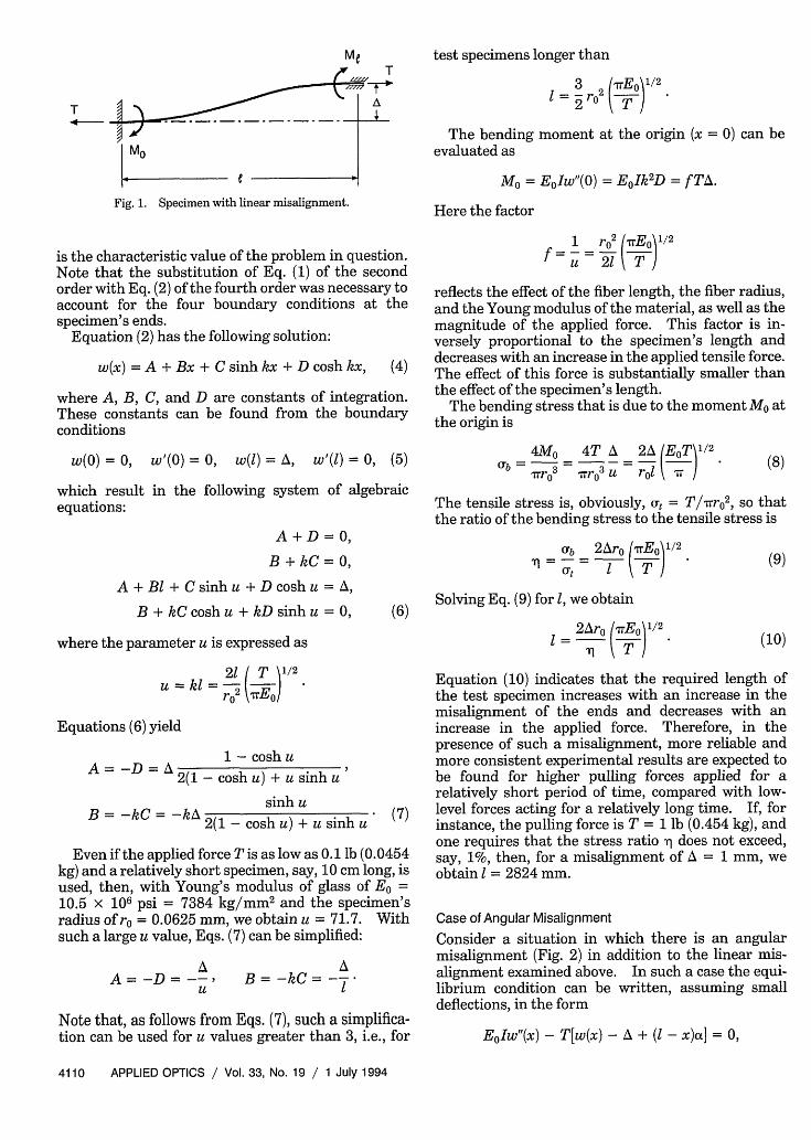
The deflection function w(x) of a glass fiber solderedinto a ferrule and subjected to tension (Fig. 1) mustsatisfy the following equilibrium condition:
E0Iw"(x) - T[w(x) - A] - Ml = 0, (1)
where E0 is Young's modulus of the glass, I = (7r/4)ro4is the moment of inertia of the fiber cross section, ro isthe fiber radius, T is the applied tensile force, Ml is thebending moment at the end x = 1, and A is themisalignment (offset) of the specimen's ends. Equa-tion (1) reflects an obvious assumption that thedeflections w(x) are small, and therefore the engineer-ing theory of bending of beams (see, for instance, Ref.3) can be applied. Equation (1) simply states thatthe external bending moments (expressed by thesecond and the third terms) should be equilibrated bythe elastic bending moment (the first term).
From Eq. (1) we obtain, by differentiation,
The author is with AT&T Bell Laboratories, Murray Hill, NewJersey 07974.
Received 3 February 1993; revised manuscript received 16September 1993.
0003-6935/94/194109-04$06.00/0.c 1994 Optical Society of America.
wW(x) - k 2w"(x) = 0,
where
T 1/2 2 T 1/2k=EI r02 7rEo
1 July 1994 / Vol. 33, No. 19 / APPLIED OPTICS 4109
(2)
(3)
MeT
T A
MO
Fig. 1. Specimen with linear misalignment.
is the characteristic value of the problem in question.Note that the substitution of Eq. (1) of the secondorder with Eq. (2) of the fourth order was necessary toaccount for the four boundary conditions at thespecimen's ends.
Equation (2) has the following solution:
w(x) = A + Bx + C sinh kx + D cosh kx, (4)
where A, B, C, and D are constants of integration.These constants can be found from the boundaryconditions
w(0) = 0, w'(0) = 0, w(l) = A, w'(l) = 0, (5)
which result in the following system of algebraicequations:
A + D = 0,
B + kC = 0,A + BI + C sinh u + D cosh u = A,
B + kC cosh u + kD sinh u = 0,
where the parameter u is expressed as
21 T 1/2
U = kl -2 TEO)
Equations (6) yield
1 - cosh uA -D A 2(1 - cosh u) + u sinh u
sinh uB= -kC= ~kA2(1 - cosh u) + u sinh u ()
Even if the applied force T is as low as 0.1 lb (0.0454kg) and a relatively short specimen, say, 10 cm long, isused, then, with Young's modulus of glass of E0 =10.5 x 10⁶ psi = 7384 kg/mm 2 and the specimen'sradius of ro = 0.0625 mm, we obtain u = 71.7. Withsuch a large u value, Eqs. (7) can be simplified:
AA= -D = -
U
AB = -kC= =-
Note that, as follows from Eqs. (7), such a simplifica-tion can be used for u values greater than 3, i.e., for
test specimens longer than
1 = 3 r02 7rE01
The bendingevaluated as
moment at the origin (x = 0) can be
M = EjIw"(O) = E0Ik2D = f TA.
Here the factor
1 r02 (7EO1/ 2
u 21 T}
reflects the effect of the fiber length, the fiber radius,and the Young modulus of the material, as well as themagnitude of the applied force. This factor is in-versely proportional to the specimen's length anddecreases with an increase in the applied tensile force.The effect of this force is substantially smaller thanthe effect of the specimen's length.
The bending stress that is due to the moment Mo atthe origin is
4Mo 4T A 2A (EoT 1/2
rb -=w - =r 3 u r_ \rr (8)
The tensile stress is, obviously, Ut = Trro 2, so thatthe ratio of the bending stress to the tensile stress is
= Ub 2Aro (ITEo /2N =-= Z ° ( T ) * ~(9)
Solving Eq. (9) for 1, we obtain
I= 2Aro (nEo) (10)
Equation (10) indicates that the required length ofthe test specimen increases with an increase in themisalignment of the ends and decreases with anincrease in the applied force. Therefore, in thepresence of such a misalignment, more reliable andmore consistent experimental results are expected tobe found for higher pulling forces applied for arelatively short period of time, compared with low-level forces acting for a relatively long time. If, forinstance, the pulling force is T = 1 lb (0.454 kg), andone requires that the stress ratio q does not exceed,say, 1%, then, for a misalignment of A = 1 mm, weobtain I = 2824 mm.
Case of Angular Misalignment
Consider a situation in which there is an angularmisalignment (Fig. 2) in addition to the linear mis-alignment examined above. In such a case the equi-librium condition can be written, assuming smalldeflections, in the form
EjIw"(x) - T[w(x) - A + ( - x)a] = 0,
4110 APPLIED OPTICS / Vol. 33, No. 19 / 1 July 1994

a T ence of angular misalignment, by the equation
T
Ta
Fig. 2 Specimen with both linear and angular misalignment.
where a is the angle that the tensile force T formswith the axis x. The double differentiation of thisequation results in Eq. (2), and therefore the solutionof the above equation is expressed by Eq. (4). Thelast boundary condition in Eqs. (5), however, shouldbe substituted for with the condition w'(1) = -a, and,accordingly, the zero in the right-hand part of the lastequation in the system of Eqs. (6) should be substi-tuted for with the -a value. Then the constants ofintegration in Eq. (4) become
kA(l - cosh u) + ( - sinh u)a-A =fl)= - I - - -1
k[2( - cosh u) + u sinh u]
kA sinh u - (1 - cosh u)axB=-kC= 2(1 - coshu) + u sinhu
or, for large u values,
kA + aA=-D=- ku
kA + atB = -kC =
u
With these constants of integration, the bendingmoment at the origin can be evaluated as
M = E0Ik 2D = TD = T(- A +
X= 2Ar (TrEo)2[ + 2 (T) 2
Solving this equation for 1, we obtain
I = I (1 + ro7 ; 'nt) (11)
where 1 is the specimen's length evaluated in accor-dance with Eq. (10), i.e., without considering theangular misalignment. If, for instance, angle a is assmall as a = 20, then, using the input data from theexample examined in the case of linear misalignment,we find that the factor, which accounts for the effectof angular misalignment, is as high as 2.55.
Probabilistic Approach
Although the fiber length, the radius, Young's modu-lus of the material, and the applied force are eitherknown or can be predicted or measured with ratherhigh accuracy, the expected or the actual misalign-ment of the fiber ends is not as well known. Thisjustifies the application of a probabilistic approach.Let us show how such an approach can be used in thecase of linear misalignment.
Treating misalignment A of the fiber ends as arandom variable, we assume that the probabilitydensity function of this variable can be described byRayleigh law (see, for instance, Ref. 4):
fA(') = D exp( 2D)
where D is related to the variance DA of variable A asD = [2/(4 + 1r)]DA. The mean value mA of themisalignment distributed according to Rayleigh law isrelated to its variance DA as follows:
and the corresponding bending stress is
4Mo 4T Ub = r 3 ' rr03 u
where the factor
2 (rEo) 12
f = rrroi' T ) 1
mA = ( + DA)+ ) = fTA,
ro2 (T ) 1/2]
- 0.6633FVq,
so that
Di = 2.2732 mA .
Using Eq. (8), we obtain the following equation forthe probability density function of the bending stress:
reflects the effects of the fiber length, the radius,Young's modulus of the material, the magnitude ofthe applied force, and the angular and the linearmisalignments on the bending stress. As in the caseof linear misalignment only, this factor is inverselyproportional to the specimen's length and decreaseswith an increase in the tensile force. The increase inthe angular misalignment results in an increase inthe bending stress. The effect of this misalignmentdecreases with an increase in the tensile force andwith linear misalignment. The ratio of bendingstress to the tensile stress is expressed, in the pres-
f,(u) = - exp(- u2/2D,),D,
(12)
where variance D, of the bending stress U is related tothe parameter D of the linear misalignment A as
- 0D ( 8 EoTDD wro 212 A - (4 + 707r) 212 ,
As is evident from this equation, variance Da can bereduced considerably (for the given variance DA) ifsufficiently long specimens are used.
1 July 1994 / Vol. 33, No. 19 / APPLIED OPTICS 4111

Table 1. Calculated Specimen Length I (m)
n
T (kg) 2 3 4 5 6 7 8
0.454 1.71 2.09 2.42 2.70 2.96 3.20 3.422.27 0.76 0.94 1.08 1.21 1.32 1.43 1.53
The probability that the bending stress U exceeds acertain level U* can be evaluated by use of Eq. (12) asfollows:
P(U> a*,) = f (U)du = exp( -U. 2/2D,).
If the allowable level U* of the bending stress isdefined as a certain percentage of the tensile stress Ut,then, for the given probability P, the allowable level ofbending stress can be determined by use of theequation
T 2 2 1/2= -r = (-2D.J1n p)112 - -- ETDlnP
i'ro rol IT
Then the minimum required length of the specimencan be evaluated as
=- 2rD T In P =- 2- 2-0D In, t ln
p 1/2.
We can calculate the required specimen length byassuming a certain probability level P and an accept-able level of bending stress Ub in comparison with theapplied tensile stress Ut. Let, for instance, the ex-pected mean value of the misalignment of the ends beMA = 0.25 mm. Then the corresponding variance is
DA = 2.2732 mA2 = 0.1421 mm2. Let us require thatthe probability P that the maximum bending stress Ubexceed, say, 1% of the nominal tensile stress Ut be aslow as 10-n (where n is a given integer). The result-ing required calculated lengths (in meters), withE = 7384 kg/mm 2 and ro = 0.0625 mm, are as shownfor T = 1 lb = 0.454 kg and T = 5 lb. = 2.27 kg inTable 1. As is evident from Table 1, the calculatedspecimen lengths are quite large.
Conclusion
Even a small linear or angular misalignment of theends of a fiber soldered into a ferrule can causeappreciable bending stress in test specimens sub-jected to tension. This stress can be minimized,however, if the specimens are made sufficiently long.If, for one reason or another, the specimens could notbe made long enough and a low misalignment couldnot be achieved, then the bending stress should beaccounted for when one is predicting the static fa-tigue characteristics of the optical glass fiber from thepull-test data.
The auther acknowledges useful discussions withG. Bubel, S. Kaufman, J. T. Krause, and R. Ku as wellas the valuable comments made by L. L. Blyler, Jr.,and especially W. W. King.
References
1. S. E. Miller and A. G. Chynoweth, Optical Fiber Telecommuni-cations (Academic, San Diego, Calif., 1979), Chap. 7, p. 191.
2. ASTM E-1012, "Standard practice for verification of specimenalignment under tensile loading," (American Society for Testingand Materials, Philadelphia, Pa., 1993).
3. E. Suhir, Structural Analysis in Microelectronic and Fiber-Optic Systems (Van Nostrand Reinhold, New York, 1991), Chap.12,pp. 170-209.
4. J. J. Tuma, ed., Engineering Mathematics Handbook, 2nd ed.(McGraw-Hill, New York, 1978), Chap. 18, p. 244.
4112 APPLIED OPTICS / Vol. 33, No. 19 / 1 July 1994