PUK 3 professional / PUK 3 professional plus · "PUK 3 professional" / "PUK 3 professional plus"...
15
OPERATING INSTRUCTIONS "PUK 3 professional" / "PUK 3 professional plus" Dear Customer This manual is intended to assist you in operating and maintaining your „PUK 3“. It is in your best interest to read this manual thoroughly, and to follow the instructions conscientiously. You will avoid malfunctioning as a result of operating errors. The device will thank you with a continuous readiness for use for years to come. Operation of the device should only be done by trained professionals and be operated according to the intended purpose of use. The manufacturer is in no way liable for any damage caused by improper use and operation. Before use please be sure to read the manual sections “General Safety Requirements” and “Personal Protection”. Please retain these instructions for reference. Note on Symbol The equipment manufactured by “Lampert Werktechnik GmbH“ fulfil the standard requirements of CE certification and are manufactured according to VDE guidelines. Use original parts only for maintenance and updating. Our customer service department with expertly trained staff, suitable resources and equipment would be pleased to help you further. The device should only be opened or modified by authorized customer service technicians, otherwise all warrantees and liability claims will be void. LAMPERT WERKTECHNIK GmbH May 2007
Transcript of PUK 3 professional / PUK 3 professional plus · "PUK 3 professional" / "PUK 3 professional plus"...

OPERATING INSTRUCTIONS
"PUK 3 professional" / "PUK 3 professional plus"
Dear Customer
This manual is intended to assist you in operating and maintaining your „PUK 3“. It is in your best interest to read this manual thoroughly, and to follow the instructions conscientiously. You will avoid malfunctioning as a result of
operating errors. The device will thank you with a continuous readiness for use for years to come.
Operation of the device should only be done by trained professionals and be operated according to the intended purpose of use. The manufacturer is
in no way liable for any damage caused by improper use and operation. Before use please be sure to read the manual sections “General Safety
Requirements” and “Personal Protection”.
Please retain these instructions for reference.
Note on Symbol
The equipment manufactured by “Lampert Werktechnik GmbH“ fulfil the standard requirements of CE certification and are manufactured according to VDE
guidelines.
Use original parts only for maintenance and updating. Our customer service department with expertly trained staff, suitable resources and equipment would
be pleased to help you further.
The device should only be opened or modified by authorized customer service technicians, otherwise all warrantees and liability claims will be
void.
LAMPERT WERKTECHNIK GmbH
May 2007
2
TABLE OF CONTENTS
SECTION
A SYMBOL USAGE 3
1 FIELD OF APPLICATION 3
2 INTRODUCTION 3
3 SAFETY RULES
3-1 General safety rules 4
3-2 Personal body protection and dangers 5
4 INSTALLATION
4-1 Set-up rules 5
4-2 Operations elements front side 6
4-3 Operations elements rear side 7
4-4 Starting up 7-9
5 SETTING OF THE PARAMETERS AND OPERATION
5-1 Adjustment of the Weldingparameter 9
5-2 Programming (only "PUK3 professional plus") 10
6 INSTRUCTIONS
6-1 Welding instructions 10
6-2 In general and pointers 11
6-3 Sharpening the electrodes 12
6-4 Care and maintenance 12
7 TECNICAL DATA
7-1 Technical data 13
7-2 Picture Symbols – Identification plate 13
8 TROUBLE SHOOTING 14
9 SPARE PARTS LIST 15
10 EG-CONFORMITY DECLARATION 15
3
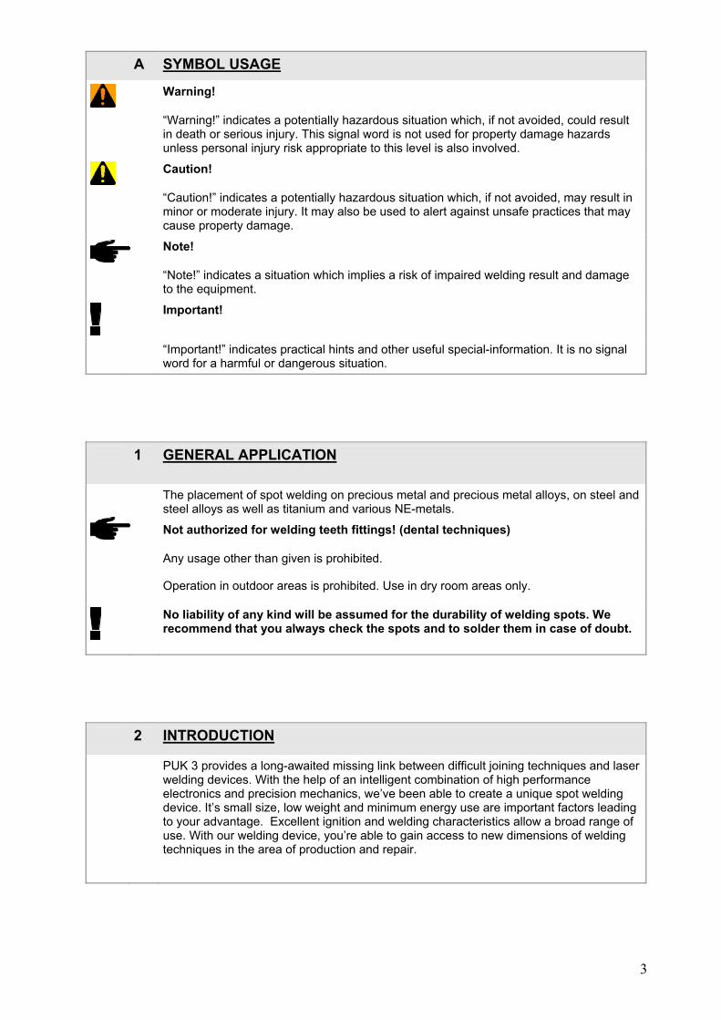
A SYMBOL USAGE
Warning!
“Warning!” indicates a potentially hazardous situation which, if not avoided, could result in death or serious injury. This signal word is not used for property damage hazards unless personal injury risk appropriate to this level is also involved.
Caution!
“Caution!” indicates a potentially hazardous situation which, if not avoided, may result in minor or moderate injury. It may also be used to alert against unsafe practices that may cause property damage.
Note!
“Note!” indicates a situation which implies a risk of impaired welding result and damage to the equipment.
Important!
“Important!” indicates practical hints and other useful special-information. It is no signal word for a harmful or dangerous situation.
1 GENERAL APPLICATION
The placement of spot welding on precious metal and precious metal alloys, on steel and steel alloys as well as titanium and various NE-metals.
Not authorized for welding teeth fittings! (dental techniques)
Any usage other than given is prohibited.
Operation in outdoor areas is prohibited. Use in dry room areas only.
No liability of any kind will be assumed for the durability of welding spots. We
recommend that you always check the spots and to solder them in case of doubt.
2 INTRODUCTION
PUK 3 provides a long-awaited missing link between difficult joining techniques and laser welding devices. With the help of an intelligent combination of high performance electronics and precision mechanics, we’ve been able to create a unique spot welding device. It’s small size, low weight and minimum energy use are important factors leading to your advantage. Excellent ignition and welding characteristics allow a broad range of use. With our welding device, you’re able to gain access to new dimensions of welding techniques in the area of production and repair.

4
3 GENERAL SAFETY INSTRUCTIONS - READ BEFORE USING
3-1 SAFETY INSTRUCTIONS
Opening the device is permitted only by trained experts. Remove the plug before opening the device and make sure that the device is without electrical power. Discharge all device components that may store electricity.
Please consult an expert should any questions arise. Our customer service team with expertly trained staff, necessary resources and equipment would be pleased to assist you further at any time.
Always use original cables that are long enough and make sure that the clamp holding the work piece is fastened properly.
Hazard conditions may be caused by electricity as well as by welding current.
It is illegal for non-professional electricians to handle parts that are directly connected to the mains power supply, except in cases of pulling the mains plug and/or operating the main power switch.
The device must be disconnected from the mains as soon as repair or service works is needed. When leaving the place of work even for a short time, make sure that the electrical outlet is blocked clearly.
Open circuit voltage is the highest and most dangerous voltage for welding current. The highest permitted open circuit voltages are contained in your national and international regulations according to the type of welding current, type of electrical source and the high or low hazard levels at the workplace.
If you believe that operating the device is not possible without creating hazardous conditions, then shut off the device and secure it against unauthorised use.
It is clear that a hazardous conditions are present when:
the device shows visible damage, or
or when functional errors occur
if it no longer functions properly.
Please follow relevant safety measures when handling gas bottles
PUK 3 can be operated in series using a mains voltage of 115V~
Yellow/green electric conductor = grounded terminal (PE) Other conductors L1 and N are connected to phase and neutral of plug.
The welding device is set for 115 V ex works!
This means that it also may be operated using 100 volts due to its tolerance of +/- 15%. Devices set to a different voltage than 115 V will be marked with a special sticker.
AUTHORIZED SERVICE PERSONNEL ONLY MAY OPEN THE DEVICE! otherwise the manufacturer`s warrantee is invalid.
IF THE DEVICE HAS BEEN MADE FOR A SPECIAL VOLTAGE, THEN SEE THE TECHNICAL DATA INDICATED ON THE DEVICE! THE POWER SWITCH MUST CORRESPOND WITH THE MAIN VOLTAGE AND THE POWER RECEPTACLE OF THE WELDING DEVICE. (See the technical data!)
PLEASE ENSURE THAT THE MAIN POWER BOX CAN SUPPORT THE USE OF THIS DEVICE WITHOUT BLOWING A FUSE
USE ONLY THE PROVIDED POWER CONNECTORS!

5
3-2 PERSONAL PROTECTION AND DANGER
Wear protective gloves on both hands during welding, since sparks and splashes are unavoidable. The protection gloves may not contain a high portion of easy melting plastic fibers. Gloves will protect from harmful UV rays during welding.
Wear appropriate clothes, with no synthetics.
Do not look into arc without protecting your eyes. Use only a welders’ face protection shield with protecting glass that conforms to regulation (minimum protection level 11).
The arc releases not only light and heat causing blindness or burning but also emits UV rays. If insufficient protection is used, the UV beams can cause very painful conjunctivital inflammation only noticeable after several hours.
Bystanders close to the arcs also should be made aware of possible dangerous conditions and should wear protective equipment. If necessary protective walls should be set up.
If welding in small rooms, ensure that there is sufficient ventilation since smoke and dangerous gases can be generated.
It is prohibited by law to weld containers that have been used for the storage of gas, fuel, mineral oil etc., even if containers have been standing empty for a long period of time. Explosions may occur during the welding process due to residue.
Note any special regulations for rooms with high fire or explosion hazards.
4 INSTALLATION
4-1 SET UP RULES
Place the device so that cool air can reach the entire outside surface without difficulty
Do not cover the device!
Always place the device on a hard non-combustible, insulated material base.
Do not allow metal dust (e.g. during abrasion work) to directly enter the device.
6
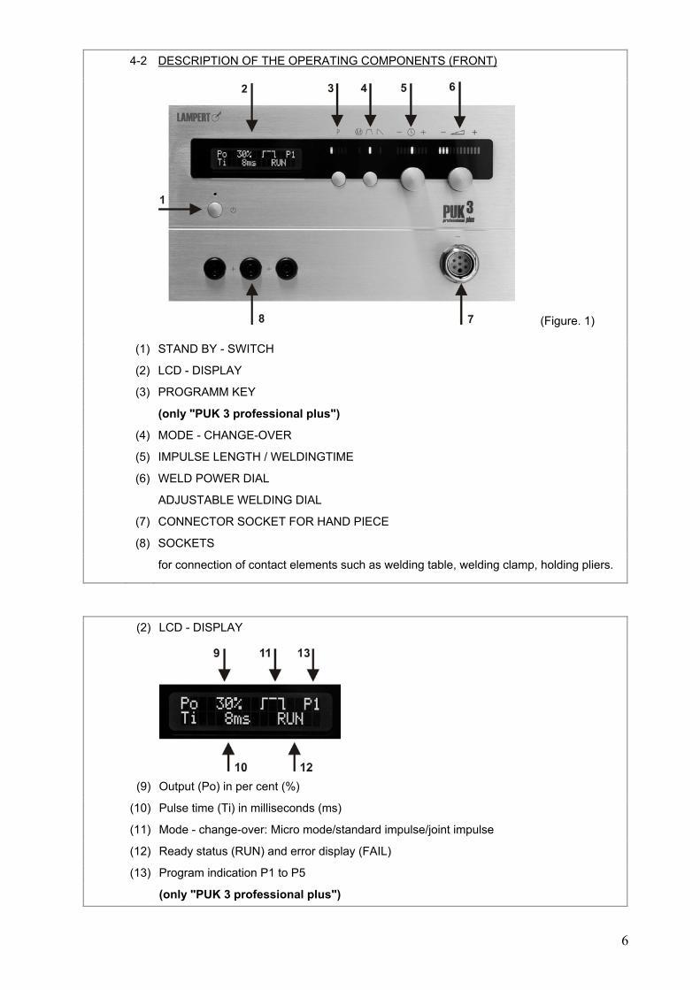
4-2 DESCRIPTION OF THE OPERATING COMPONENTS (FRONT)
(Figure. 1)
(1) STAND BY - SWITCH
(2) LCD - DISPLAY
(3) PROGRAMM KEY
(only "PUK 3 professional plus")
(4) MODE - CHANGE-OVER
(5) IMPULSE LENGTH / WELDINGTIME
(6) WELD POWER DIAL
ADJUSTABLE WELDING DIAL
(7) CONNECTOR SOCKET FOR HAND PIECE
(8) SOCKETS
for connection of contact elements such as welding table, welding clamp, holding pliers.
(2) LCD - DISPLAY
(9) Output (Po) in per cent (%)
(10) Pulse time (Ti) in milliseconds (ms)
(11) Mode - change-over: Micro mode/standard impulse/joint impulse
(12) Ready status (RUN) and error display (FAIL)
(13) Program indication P1 to P5
(only "PUK 3 professional plus")
7
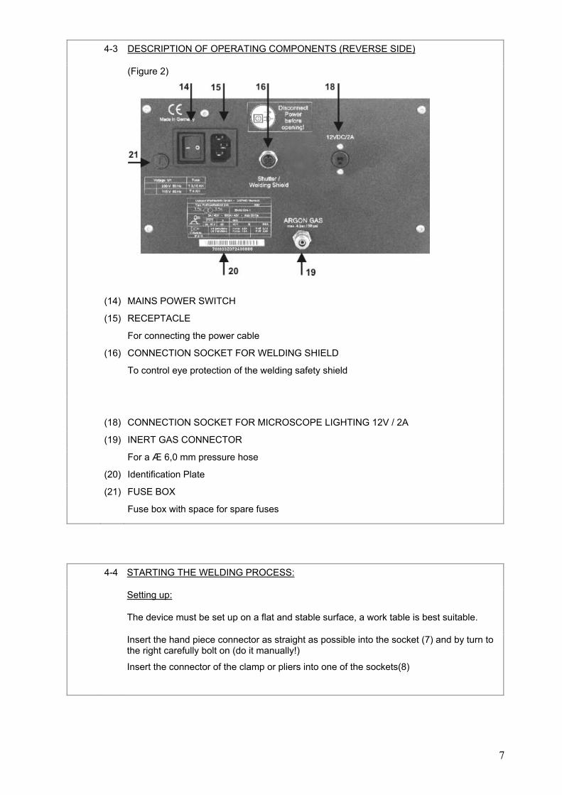
4-3 DESCRIPTION OF OPERATING COMPONENTS (REVERSE SIDE)
(Figure 2)
(14) MAINS POWER SWITCH
(15) RECEPTACLE
For connecting the power cable
(16) CONNECTION SOCKET FOR WELDING SHIELD
To control eye protection of the welding safety shield
(18) CONNECTION SOCKET FOR MICROSCOPE LIGHTING 12V / 2A
(19) INERT GAS CONNECTOR
For a Æ 6,0 mm pressure hose
(20) Identification Plate
(21) FUSE BOX
Fuse box with space for spare fuses
4-4 STARTING THE WELDING PROCESS:
Setting up:
The device must be set up on a flat and stable surface, a work table is best suitable.
Insert the hand piece connector as straight as possible into the socket (7) and by turn to the right carefully bolt on (do it manually!)
Insert the connector of the clamp or pliers into one of the sockets(8)
8
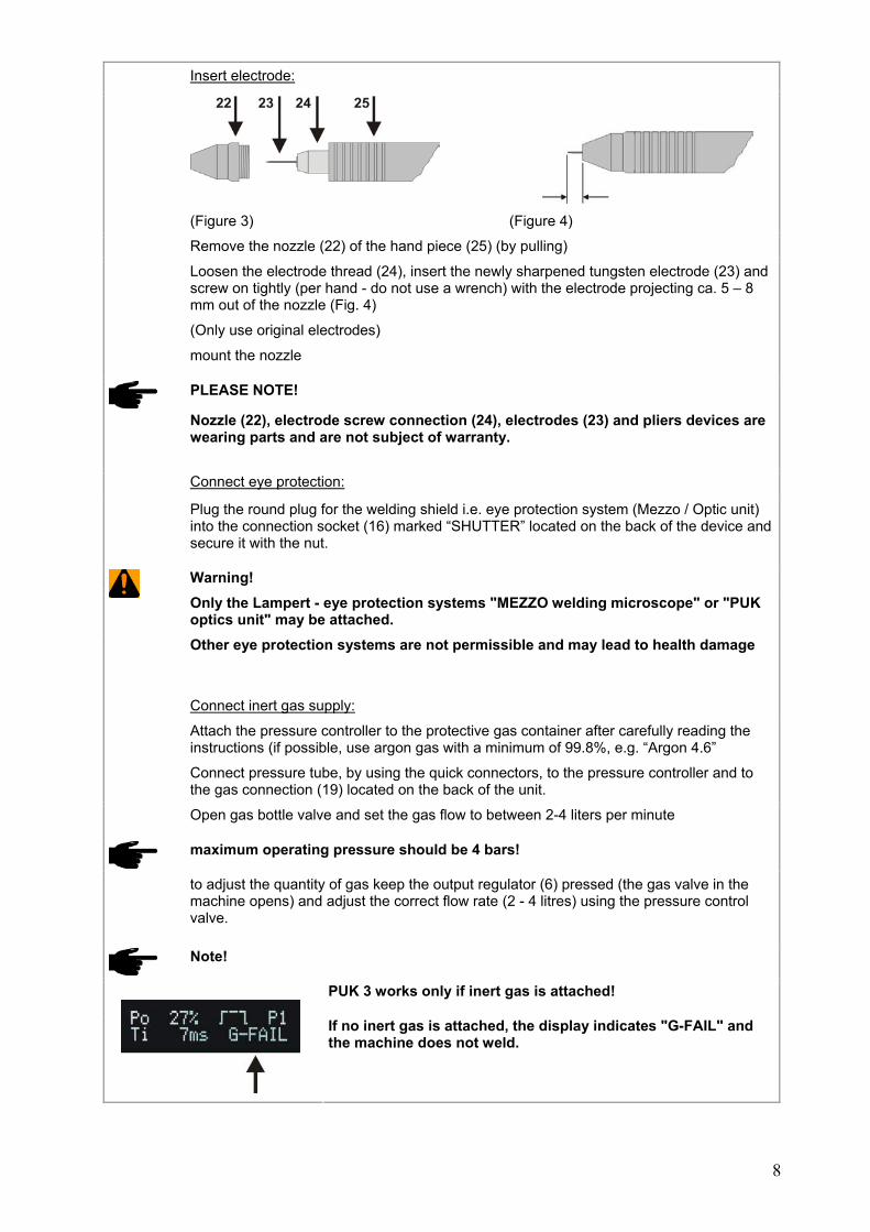
Insert electrode:
(Figure 3) (Figure 4)
Remove the nozzle (22) of the hand piece (25) (by pulling)
Loosen the electrode thread (24), insert the newly sharpened tungsten electrode (23) and screw on tightly (per hand - do not use a wrench) with the electrode projecting ca. 5 – 8 mm out of the nozzle (Fig. 4)
(Only use original electrodes)
mount the nozzle
PLEASE NOTE!
Nozzle (22), electrode screw connection (24), electrodes (23) and pliers devices are wearing parts and are not subject of warranty.
Connect eye protection:
Plug the round plug for the welding shield i.e. eye protection system (Mezzo / Optic unit) into the connection socket (16) marked “SHUTTER” located on the back of the device and secure it with the nut.
Warning! Only the Lampert - eye protection systems "MEZZO welding microscope" or "PUK
optics unit" may be attached. Other eye protection systems are not permissible and may lead to health damage
Connect inert gas supply:
Attach the pressure controller to the protective gas container after carefully reading the instructions (if possible, use argon gas with a minimum of 99.8%, e.g. “Argon 4.6”
Connect pressure tube, by using the quick connectors, to the pressure controller and to the gas connection (19) located on the back of the unit.
Open gas bottle valve and set the gas flow to between 2-4 liters per minute
maximum operating pressure should be 4 bars!
to adjust the quantity of gas keep the output regulator (6) pressed (the gas valve in the machine opens) and adjust the correct flow rate (2 - 4 litres) using the pressure control valve.
Note!
PUK 3 works only if inert gas is attached!
If no inert gas is attached, the display indicates "G-FAIL" and the machine does not weld.
9
Connect power supply:
Connect mains lead to the back of the unit (15) and plug into the mains outlet.
Switch the mains power switch (14) to „ON“ – the device will perform an automatic test.
Note! Please read the instructions on the connected eye protection devices such as the
PUK - optic unit (welding shield) or MEZZO microscope with (welding shield)! Caution! Clamps or pliers, which are attached to the PUK 3, could be conducting voltage, as
soon as the power mains switch is turned on. Make sure that these components do not touch any electrical conducting parts such as the casing
5 SET UP OF THE PARAMETERS AND OPERATION
When switching on on the machine always starts in the basic adjustment
Standard impulse, welding time 7ms and output 20%
The basic adjustment for impulse, welding time and the total capacity range is characterized by blue LED's.
Important! We recommend beginners to always work within the "blue range (blue LED's)". Thus to
change "only" the welding output (9).
If you are familiar with the technology, you can change of course also impulse mode and welding time.
The machine stores automatically after each welding procedure the current welding parameters.
By pressing the welding time controller (5) these parameters can be called.
After switching on the machine or "operation error" the last parameter can be called again.
5-1 SETTING THE WELDING PARAMETER
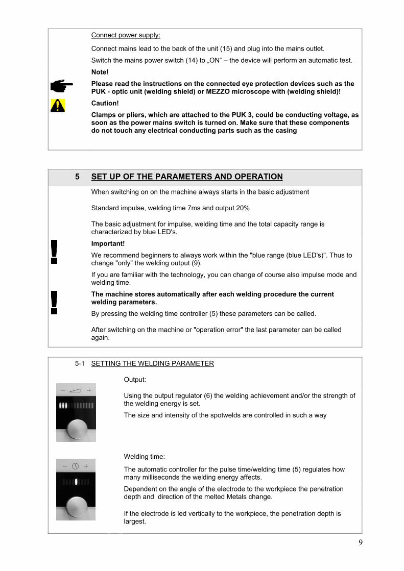
Output:
Using the output regulator (6) the welding achievement and/or the strength of the welding energy is set.
The size and intensity of the spotwelds are controlled in such a way
Welding time:
The automatic controller for the pulse time/welding time (5) regulates how many milliseconds the welding energy affects.
Dependent on the angle of the electrode to the workpiece the penetration depth and direction of the melted Metals change.
If the electrode is led vertically to the workpiece, the penetration depth is largest.
10
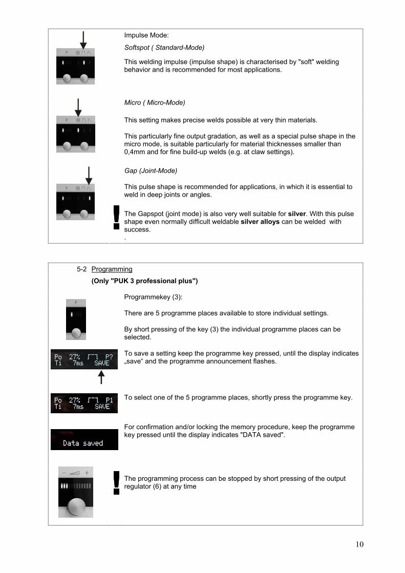
Impulse Mode:
Softspot ( Standard-Mode)
This welding impulse (impulse shape) is characterised by "soft" welding behavior and is recommended for most applications.
Micro ( Micro-Mode)
This setting makes precise welds possible at very thin materials.
This particularly fine output gradation, as well as a special pulse shape in the micro mode, is suitable particularly for material thicknesses smaller than 0,4mm and for fine build-up welds (e.g. at claw settings).
Gap (Joint-Mode)
This pulse shape is recommended for applications, in which it is essential to weld in deep joints or angles.
The Gapspot (joint mode) is also very well suitable for silver. With this pulse shape even normally difficult weldable silver alloys can be welded with success. .
5-2 Programming
(Only "PUK 3 professional plus")
Programmekey (3):
There are 5 programme places available to store individual settings.
By short pressing of the key (3) the individual programme places can be selected.
To save a setting keep the programme key pressed, until the display indicates „save“ and the programme announcement flashes.
To select one of the 5 programme places, shortly press the programme key.
For confirmation and/or locking the memory procedure, keep the programme key pressed until the display indicates "DATA saved".
The programming process can be stopped by short pressing of the output regulator (6) at any time
11
6 INSTRUCTIONS
6-1 WELDING INSTRUCTIONS
Connect the clamp to a blank metal location on the work piece
or
Make sure there is good contact between work piece and welding table
Touch the electrode tip to the spot to be welded until the welding is done
without, or with minimum pressure to the electrode tip!
The welding procedure is automatically done:
o Safety gas encases the welding spot
o A signal announces the arc
o The light arc appears
o Safety gas supply ceases
The welding procedure may be stopped anytime by removing the electrode from the work piece
6-2 IN GENERAL AND POINTERS
Important!
Always work with sharpened electrodes!
This is the best way to achieve maximum results.
Make sure the work piece has enough contact to the clamp. If contact problems occur, make sure the clamp is in contact with a metallic blank location.
Never weld „hands free“, this means; support both hands i.e. on the workbench during welding. Shaking hands falsify the parameters of the device. .
Apply only minimum pressure onto the electrode tip.
Weld only with minimum gas pressure!
2 to 4 l/min are often sufficient.
TIPS
Take enough time to get to know your device.
Try out various power levels of the device.
Keep in mind that various materials react differently during welding.

12
Consider the thickness of the material when you choose the power level.
Try to touch the work piece to be welded as precisely as possible.
With just a little experience you will discover how the angle in which you touch the needle to the work piece will effect the flow direction of the welding point.
Touching the work piece in an angle of 90° will give you the deepest welding point.
A saw or file burr can serve well as a „welding addition“.
For deeply located welding spots, the electrode should be longer.
It may be helpful to use a graver to broach grains to later weld them on.
It may be helpful to use wire as a welding addition to close holes or as reinforcement.
If ignition problems occur it is helpful to apply light pressure to the needle from the side, as if you were scratching the surface of the work piece.
6-3 SHARPENING THE ELECTRODES
The electrodes should be sharpened with a diamond grinder with fine or medium grain.
The angle should be ca. 15° (Fig.)
6-4 CARE AND MAINTENENCE
The PUK 3 needs, under ordinary working conditions, only minimum care and maintenance. Remembering a couple of points is crucial, though, to ensure proper functioning and a long life for your welding device.
Regularly check the power plug and power cables, as well as welding cables for damage.
Ensure that the hand piece parts are easy to operate.
If necessary, clean the electrode thread of the hand piece to ensure an optimal contact with the electrode
Warning!
IF FUSES NEED TO BE REPLACED, REPLACE ONLY WITH THE SAME VALUES. IF DAMAGES OCCUR AFTER INSTALLING INAPPROPRIATE FUSES (I.E. TOO STRONG) THE WARRANTY BECOMES INVALID.
AUTHORIZED PERSONNEL MAY ONLY OPEN THE DEVICE!
13
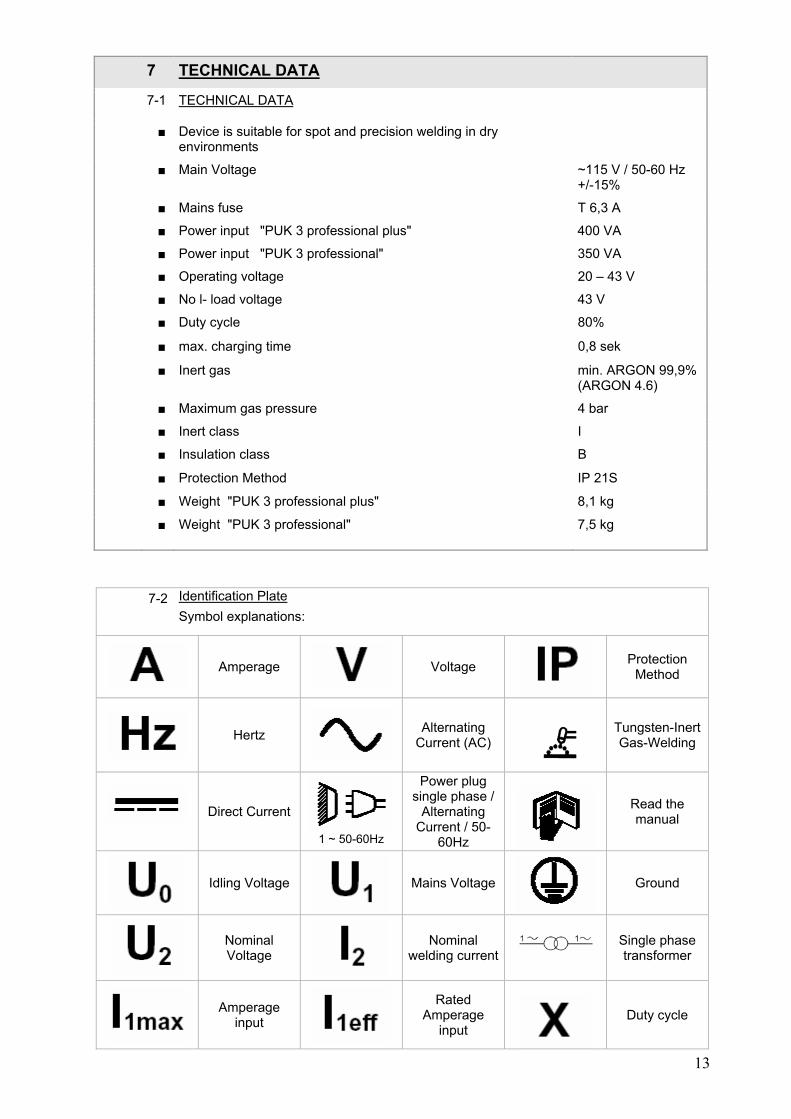
7 TECHNICAL DATA
7-1 TECHNICAL DATA
■ Device is suitable for spot and precision welding in dry environments
■ Main Voltage ~115 V / 50-60 Hz +/-15%
■ Mains fuse T 6,3 A
■ Power input "PUK 3 professional plus" 400 VA
■ Power input "PUK 3 professional" 350 VA
■ Operating voltage 20 – 43 V
■ No l- load voltage 43 V
■ Duty cycle 80%
■ max. charging time 0,8 sek
■ Inert gas min. ARGON 99,9% (ARGON 4.6)
■ Maximum gas pressure 4 bar
■ Inert class I
■ Insulation class B
■ Protection Method IP 21S
■ Weight "PUK 3 professional plus" 8,1 kg
■ Weight "PUK 3 professional" 7,5 kg
7-2 Identification Plate
Symbol explanations:
Amperage
Voltage
Protection Method
Hertz
Alternating Current (AC)
Tungsten-Inert Gas-Welding
Direct Current
1 ~ 50-60Hz
Power plug single phase /
Alternating Current / 50-
60Hz
Read the manual
Idling Voltage
Mains Voltage
Ground
Nominal Voltage
Nominal welding current
Single phase transformer
Amperage input
Rated Amperage
input
Duty cycle
14
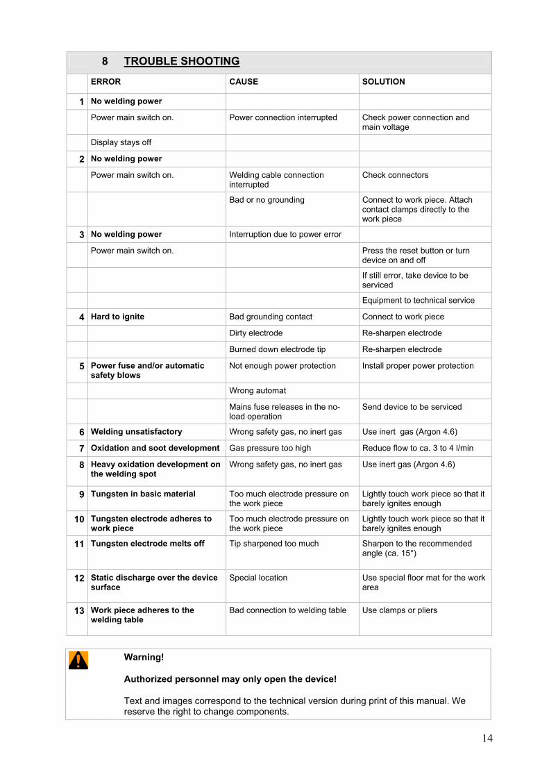
8 TROUBLE SHOOTING
ERROR CAUSE SOLUTION
1 No welding power
Power main switch on. Power connection interrupted Check power connection and main voltage
Display stays off
2 No welding power
Power main switch on. Welding cable connection interrupted
Check connectors
Bad or no grounding Connect to work piece. Attach contact clamps directly to the work piece
3 No welding power Interruption due to power error
Power main switch on. Press the reset button or turn device on and off
If still error, take device to be serviced
Equipment to technical service
4 Hard to ignite Bad grounding contact Connect to work piece
Dirty electrode Re-sharpen electrode
Burned down electrode tip Re-sharpen electrode
5 Power fuse and/or automatic safety blows
Not enough power protection Install proper power protection
Wrong automat
Mains fuse releases in the no-load operation
Send device to be serviced
6 Welding unsatisfactory Wrong safety gas, no inert gas Use inert gas (Argon 4.6)
7 Oxidation and soot development Gas pressure too high Reduce flow to ca. 3 to 4 l/min
8 Heavy oxidation development on the welding spot
Wrong safety gas, no inert gas Use inert gas (Argon 4.6)
9 Tungsten in basic material Too much electrode pressure on the work piece
Lightly touch work piece so that it barely ignites enough
10 Tungsten electrode adheres to work piece
Too much electrode pressure on the work piece
Lightly touch work piece so that it barely ignites enough
11 Tungsten electrode melts off Tip sharpened too much Sharpen to the recommended angle (ca. 15°)
12 Static discharge over the device surface
Special location Use special floor mat for the work area
13 Work piece adheres to the welding table
Bad connection to welding table Use clamps or pliers
Warning!
Authorized personnel may only open the device!
Text and images correspond to the technical version during print of this manual. We reserve the right to change components.
15
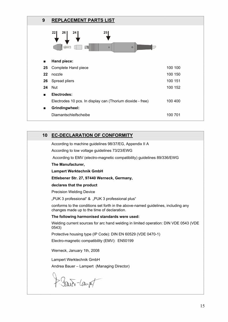
9 REPLACEMENT PARTS LIST
■ Hand piece:
25 Complete Hand piece 100 100
22 nozzle 100 150
26 Spread pliers 100 151
24 Nut 100 152
■ Electrodes:
Electrodes 10 pcs. In display can (Thorium dioxide - free) 100 400
■ Grindingwheel:
Diamantschleifscheibe 100 701
10 EC-DECLARATION OF CONFORMITY
According to machine guidelines 98/37/EG, Appendix II A
According to low voltage guidelines 73/23/EWG
According to EMV (electro-magnetic compatibility) guidelines 89/336/EWG
The Manufacturer,
Lampert Werktechnik GmbH
Ettlebener Str. 27, 97440 Werneck, Germany,
declares that the product
Precision Welding Device
„PUK 3 professional“ & „PUK 3 professional plus“
conforms to the conditions set forth in the above-named guidelines, including any changes made up to the time of declaration.
The following harmonised standards were used: Welding current sources for arc hand welding in limited operation: DIN VDE 0543 (VDE
0543)
Protective housing type (IP Code): DIN EN 60529 (VDE 0470-1)
Electro-magnetic compatibility (EMV): EN50199
Werneck, January 1th, 2008
Lampert Werktechnik GmbH
Andrea Bauer – Lampert (Managing Director)