Proximal Femur Nailing System Surgical Technique · Features of the CarboFix Proximal Femur Nailing...
24
Proximal Femur Nailing System Surgical Technique www.carboͲfix.com
Transcript of Proximal Femur Nailing System Surgical Technique · Features of the CarboFix Proximal Femur Nailing...
Proximal Femur Nailing SystemSurgical Technique
www.carbo fix.com

IntroductionImplantsThe Nail and Lag Screw are made of longitudinal continuous carbon fiber reinforced
polymer (PEEK). The screws are made of Titanium-alloy (Ti-6Al-4V).
Features of the CarboFix Proximal Femur Nailing System:
• Anatomically shaped Proximal Femur Nail with a slight bend close to its proximal end
(M-L Bend) of 5 degrees, and a Caput-collum-diaphyseal angle (CCD) of 130 degrees.
• Lag Screw is intended for insertion through the Nail proximal screw-hole, into the
femoral head. It is available in varying lengths.
• The Proximal Femur nail is used in an antegrade approach.
For further information please refer to the product Instructions for Use.
The Nail and Lag Screw are supplied sterile.
Implants dimensions are as follows:
Proximal Femur Nail
Proximal Femur Nail
Lag Screw
Lag ScrewScrews
6.85 10.4

Set Screw
The Piccolo Composite Proximal Femur Nail is provided with both a short
Set Screw ("Sliding Set Screw"), which eliminates Lag Screw rotation, but
allows sliding, and a longer Set Screw ("Locking Set Screw"), which also
limits Lag Screw sliding.
[A Retrograde Femoral Case]

Instrumentation
Access Guide Wire (Ø3.2mm)
Marks the entry point into the medulla canal, and the
trajectory.
Awl
Used to access the medullary canal for insertion of the
Nail. The Awl can be positioned over the Access Guide
Wire.
Entry Portal & Entry Trocar
The Entry Portal is a soft tissue protector used during soft
tissue tunneling and reaming.
The Entry Trocar is used for soft tissue tunneling at the
access point. It accommodates a Ø3.2mm Access Guide
Wire. The Trocar is locked to the Entry Portal by turning it
clockwise.
Ø17x300mm Drill Bit
Used to access the medullary canal. It is to accommodate a
Ø3.2mm Access Guide Wire.

Ball Tip Guide Wire (Ø2.5mm)
Assists in fracture reduction, reaming and medulla canal length
measurement. Compatible with conventional reamer sets. Ball
Tip diameter is 4.5mm.
Supplied sterile; packed separately, for single use.
Guide Wire Ruler
Measures the required nail length over the proprietary Ball-Tip
Guide Wire.
Radiographic Ruler
Used to determine the required Nail diameter and length.
Guide Wire Exchange Tube
Used for replacing the Ball-Tip Guide Wire with the Ø2.5mm
Guide Wire.
Supplied sterile; packed separately, for single use.
Guide Wire (Ø2.5mm)
The Ø2.5mm Guide Wire is used for Nail insertion into the medulla canal.
It may be supplied sterile; packed separately, for single use.
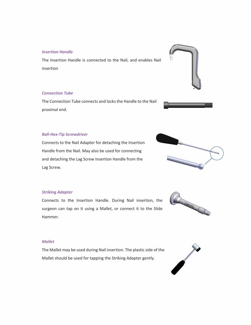
Insertion Handle
The Insertion Handle is connected to the Nail, and enables Nail
insertion
Connection Tube
The Connection Tube connects and locks the Handle to the Nail
proximal end.
Ball Hex Tip Screwdriver
Connects to the Nail Adapter for detaching the Insertion
Handle from the Nail. May also be used for connecting
and detaching the Lag Screw Insertion Handle from the
Lag Screw.
Striking Adapter
Connects to the Insertion Handle. During Nail insertion, the
surgeon can tap on it using a Mallet, or connect it to the Slide
Hammer.
Mallet
The Mallet may be used during Nail insertion. The plastic side of the
Mallet should be used for tapping the Striking Adapter gently.
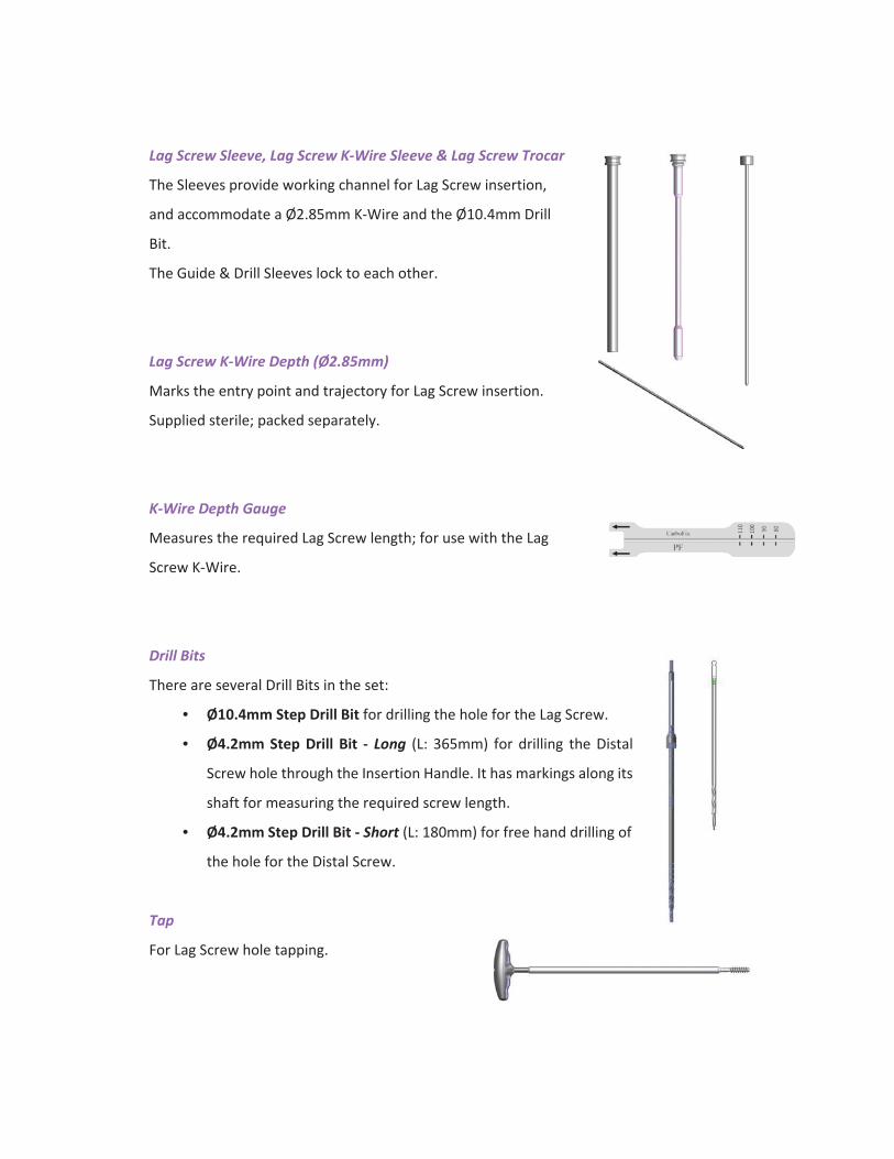
Lag Screw Sleeve, Lag Screw K Wire Sleeve & Lag Screw Trocar
The Sleeves provide working channel for Lag Screw insertion,
and accommodate a Ø2.85mm K-Wire and the Ø10.4mm Drill
Bit.
The Guide & Drill Sleeves lock to each other.
Lag Screw K Wire Depth (Ø2.85mm)
Marks the entry point and trajectory for Lag Screw insertion.
Supplied sterile; packed separately.
K Wire Depth Gauge
Measures the required Lag Screw length; for use with the Lag
Screw K-Wire.
Drill Bits
There are several Drill Bits in the set:
• Ø10.4mm Step Drill Bit for drilling the hole for the Lag Screw.
• Ø4.2mm Step Drill Bit Long (L: 365mm) for drilling the Distal
Screw hole through the Insertion Handle. It has markings along its
shaft for measuring the required screw length.
• Ø4.2mm Step Drill Bit Short (L: 180mm) for free hand drilling of
the hole for the Distal Screw.
Tap
For Lag Screw hole tapping.
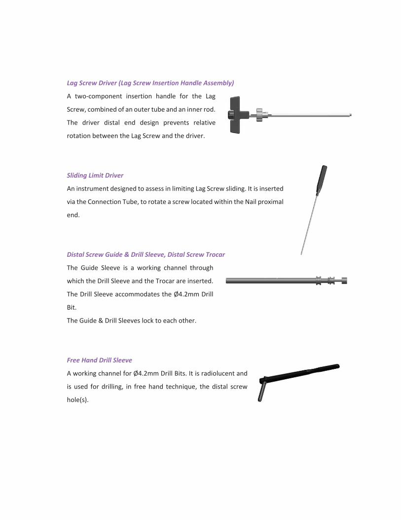
Lag Screw Driver (Lag Screw Insertion Handle Assembly)
A two-component insertion handle for the Lag
Screw, combined of an outer tube and an inner rod.
The driver distal end design prevents relative
rotation between the Lag Screw and the driver.
Sliding Limit Driver
An instrument designed to assess in limiting Lag Screw sliding. It is inserted
via the Connection Tube, to rotate a screw located within the Nail proximal
end.
Distal Screw Guide & Drill Sleeve, Distal Screw Trocar
The Guide Sleeve is a working channel through
which the Drill Sleeve and the Trocar are inserted.
The Drill Sleeve accommodates the Ø4.2mm Drill
Bit.
The Guide & Drill Sleeves lock to each other.
Free Hand Drill Sleeve
A working channel for Ø4.2mm Drill Bits. It is radiolucent and
is used for drilling, in free hand technique, the distal screw
hole(s).
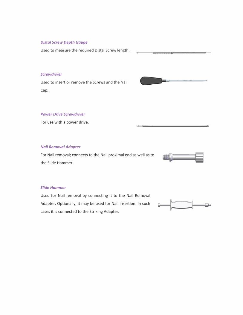
Distal Screw Depth Gauge
Used to measure the required Distal Screw length.
Screwdriver
Used to insert or remove the Screws and the Nail
Cap.
Power Drive Screwdriver
For use with a power drive.
Nail Removal Adapter
For Nail removal; connects to the Nail proximal end as well as to
the Slide Hammer.
Slide Hammer
Used for Nail removal by connecting it to the Nail Removal
Adapter. Optionally, it may be used for Nail insertion. In such
cases it is connected to the Striking Adapter.
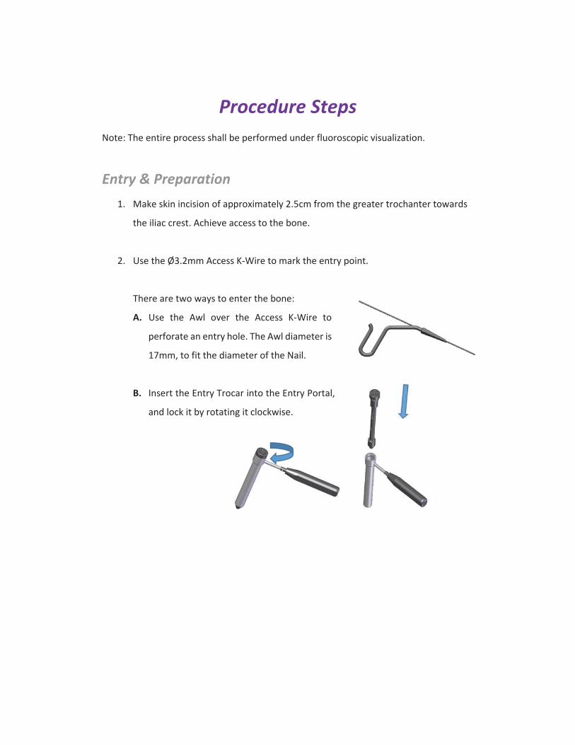
Procedure StepsNote: The entire process shall be performed under fluoroscopic visualization.
Entry & Preparation1. Make skin incision of approximately 2.5cm from the greater trochanter towards
the iliac crest. Achieve access to the bone.
2. Use the Ø3.2mm Access K Wire to mark the entry point.
There are two ways to enter the bone:
A. Use the Awl over the Access K Wire to
perforate an entry hole. The Awl diameter is
17mm, to fit the diameter of the Nail.
B. Insert the Entry Trocar into the Entry Portal,
and lock it by rotating it clockwise.

Insert The Portal Assembly over the K Wire, so
that the K Wire passes through the center hole
of the Entry Trocar;
Use the adjacent holes of the Entry Trocar in
order to improve K Wire position, if required:
Rotate the Entry Trocar so that the holes
are located as desired.
Insert a K Wire through the desired hole,
and remove the one that was incorrectly
placed.
Remove the Entry Trocar.
Use the Ø17mm Drill Bit over the K Wire to
access the bone.
3. For Long Nails Insert the Ball Tip Guide Wire into the medulla canal past the
fracture line. Perform reaming if desired. The Ball Tip Guide Wire can be used with
any conventional intramedullary flexible femoral reaming system, and according
to its instructions for use. The Guide Wire shaft diameter is 2.5mm, and the Ball
Tip diameter is 4.5mm.
Final reaming should be 1–1.5mm larger than the selected Nail diameter.

Nail Measurement (for Long Nails)
4. Measure the Femur length and diameter using a
Radiographic Ruler.
Optional: the required nail length can be
measured by using the Guide Wire Ruler. A
marker on the Ball Tip Guide Wire marks the
required nail length.
5. Use a Guide Wire Exchange Tube to exchange the Ball Tip Guide Wire by the
Ø2.5mm Guide Wire, on which the nail will be inserted.
Nail Insertion6. Connect the Handle to the Nail proximal end using
the Connection Tube.
Make sure the protrusions on the Insertion Handle
match the grooves on the nail. Verify the nail is
oriented properly.
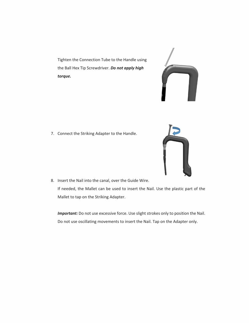
Tighten the Connection Tube to the Handle using
the Ball Hex Tip Screwdriver. Do not apply high
torque.
7. Connect the Striking Adapter to the Handle.
8. Insert the Nail into the canal, over the Guide Wire.
If needed, the Mallet can be used to insert the Nail. Use the plastic part of the
Mallet to tap on the Striking Adapter.
Important: Do not use excessive force. Use slight strokes only to position the Nail.
Do not use oscillating movements to insert the Nail. Tap on the Adapter only.
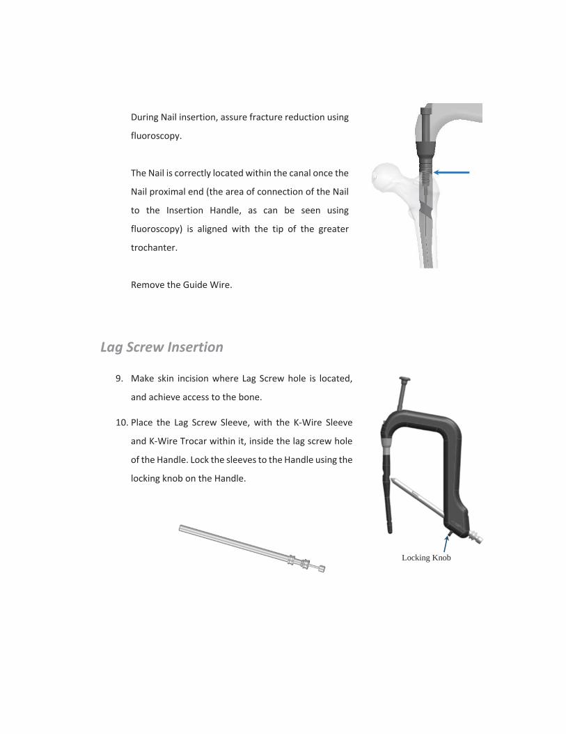
During Nail insertion, assure fracture reduction using
fluoroscopy.
The Nail is correctly located within the canal once the
Nail proximal end (the area of connection of the Nail
to the Insertion Handle, as can be seen using
fluoroscopy) is aligned with the tip of the greater
trochanter.
Remove the Guide Wire.
Lag Screw Insertion
9. Make skin incision where Lag Screw hole is located,
and achieve access to the bone.
10. Place the Lag Screw Sleeve, with the K Wire Sleeve
and K Wire Trocar within it, inside the lag screw hole
of the Handle. Lock the sleeves to the Handle using the
locking knob on the Handle.
Locking Knob

Remove the Trocar and insert a Ø2.85mm K Wire
through the K Wire Sleeve.
Ensure that the sleeves are in contact with the lateral
cortex, while verifying the anatomic position under
fluoroscopy (AP and Lateral fluoroscopy): the K Wire
shall be positioned in the inferior 1/3rd of the cervical
femur.
11. Evaluate the required Lag Screw length using the Lag
Screw Depth Gauge over the K Wire.
12. Remove the K Wire Sleeve.

13. Under fluoroscopy drill a hole for the Lag Screw using
the cannulated Step Drill Bit over the Lag Screw K
Wire. The distal tip of the Step Drill Bit shall get as far
as the Lag Screw distal tip shall be located. Verify that
the sleeves are in contact with the bone.
A stopper provided on the Drill Bit can be set to the
desired drilling depth based on the Lag Screw length
evaluation.
Verify the Lag Screw length according to the Step
Drill Bit scale. The distal part of the Step Drill Bit is
marked with lines indicating the available Lag Screw
lengths, at 10 mm steps, with the most proximal
line corresponding to a 110 mm long Lag Screw.
Remove the Step Drill Bit.
Prepare the hole created for Lag Screw insertion
with the help of the cannulated Screw Tap over the
Lag Screw K Wire.
Remove the Screw Tap.
LengthIndication
Stopper

14. Connect the Lag Screw Driver to the selected Lag Screw. Align the Lag Screw Driver
tube with the recesses at the Lag Screw proximal end, and rotate its rod clockwise,
to thread it into the Lag Screw.
The Ball Hex Tip Screwdriver can be used for final tightening. Do not apply high
torque.
15. Insert the Lag Screw, through the Lag Screw
Sleeve, while verifying proper positioning of the
fracture. The Lag Screw Driver is marked with lines
indicating insertion direction – make sure one of
the marks is aligned with the mark on the Handle.

16. If desired – compaction may be performed;
rotate the knob on the Lag Screw Driver to
achieve the desired compaction.
Compaction of up to 15mm can be achieved.
17. Select the required Set Screw.
Use the Sliding Limit Driver to insert the Set Screw
through the Connection Tube into the nail proximal
end.
Gently rotate the Set Screw within the Nail proximal
end clockwise to slightly tighten the Set Screw.
Remove the Lag Screw Driver by counterclockwise
rotation of its rod. The Ball Hex Tip Screwdriver may
be used.
Remove the Lag Screw Sleeve and the K Wire.
Distal Screws18. Make skin incision where Distal Screw hole is located, and achieve access to the
bone.
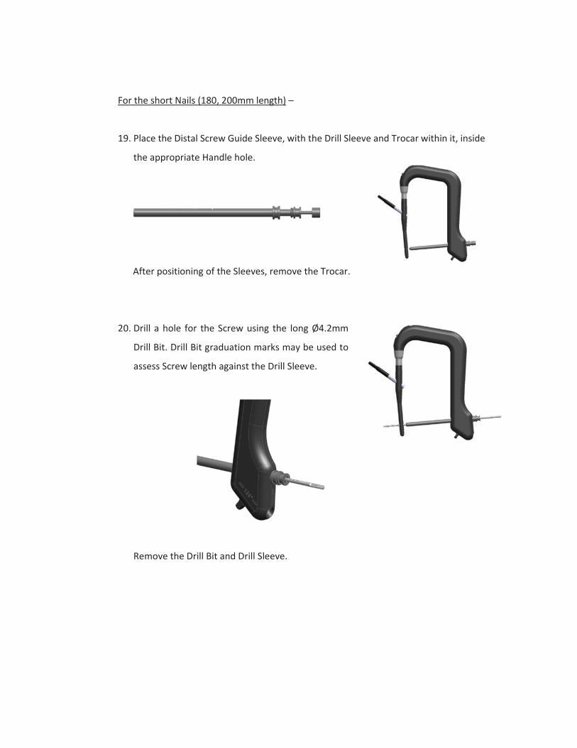
For the short Nails (180, 200mm length) –
19. Place the Distal Screw Guide Sleeve, with the Drill Sleeve and Trocar within it, inside
the appropriate Handle hole.
After positioning of the Sleeves, remove the Trocar.
20. Drill a hole for the Screw using the long Ø4.2mm
Drill Bit. Drill Bit graduation marks may be used to
assess Screw length against the Drill Sleeve.
Remove the Drill Bit and Drill Sleeve.

21. Select the appropriate length of the Ø5.0mm
Screw, by using the Distal Screw Depth Gauge
and/or the Drill Bit graduation marks (as indicated
above).
22. Insert the Screw through the Guide Sleeve, by
using the Screwdriver (Power Screwdriver
could also be used).
Remove the Screwdriver and Guide Sleeve.
Note: Alternatively, “free hand” drilling may be performed; in such case, Please
Follow the next steps.
For the Long Nails (300 – 460mm length) –
23. Distal drilling is performed in “free hand” technique.
Tiny tantalum rods markers, located near the distal holes, assist in locating the
center of the holes.

Upon proper positioning, while the x ray beam is perpendicular to the hole, the 2
radiopaque markers at each side of the hole should be aligned into a single dot. In
proper positioning a single dot should be seen at each side of the hole.
Drill a hole for the Interlocking Screw using the
short Ø4.2mm Step Drill Bit through the Free
Hand Drill Sleeve, in free hand technique.
24. Select the appropriate length of the Ø5.0mm Screw, by using the Distal Screw Depth
Gauge.
25. Insert the Screw by using the Screwdriver (Power Screwdriver could also be used).
Incorrect Alignment of Markers forDistal Screws Insertion
RadiopaqueMarkers
Hole forScrew
X
Correct Alignment of Markers for DistalScrews Insertion
RadiopaqueMarkers
Hole forScrew

Nail Cap Insertion
26. Remove the Connection Tube (counterclockwise
rotation) and disconnect the Handle from the
Nail.
27. The Nail Cap shall be inserted by using the
Screwdriver.
There are 3 available Nail Cap lengths: 0, 5 &
10mm.
The Nail Cap incorporates two embedded radiopaque markers for visualization
under fluoroscopy.
28. Close the bone penetration points according to the surgical procedure.

Nail Removal
1. Make skin incision and expose the bone entry hole.
2. Connect the Screwdriver to the Nail Cap at the Nail proximal
end, and remove the Cap by counter clockwise rotation.
3. Use the Sliding Limit Driver to release the Lag Screw – rotate
the Set Screw counterclockwise.
4. Make skin incision where the distal Screw is located. Using the
Screwdriver, remove the Screw by counter clockwise rotation.
5. Make skin incision where the Lag Screw is located. Connect the
Lag Screw Driver to the Lag Screw and remove the Lag Screw
by counterclockwise rotation.
6. Screw the Nail Removal Adapter onto the nail’s proximal end.
7. Connect the Slide Hammer to the Nail Removal Adapter.
Use light strokes of the Slide Hammer to remove the Nail
from the bone.
8. Close the penetration points according to the surgical
procedure.

1
Ver.
002_
0420
16
For detailed procedure, indications, contraindications, possible adverse event, warnings and precautions, refer to the Instructions for Use
Caution: In the U.S.A., federal law restricts this device to sale by or on the order of a physician.
MANUFACTURED BY:
CarboFix Orthopedics Ltd.11 Ha’hoshlim St.,Herzeliya 4672411 , IsraelTel: +972 9 9511511Fax: +972 9 9548939E Mail: info@carbo fix.com
Patents are pending
EC AUTHORIZED REPRESENTATIVE:
MEDNET GmbHBorkstrasse 10, 48163 MünsterGermany
www.carbo fix.com
U.S.A. OFFICE:
CarboFix Orthopedics Inc.7183-1 Beach Drive SWOcean Isle Beach, NC 28469, USATel: 1 800 408 0120
E Mail: usa@carbo fix.com