Proton Exchange Membrane Fuel Cells - Platinum … Exchange Membrane Fuel Cells PROGRESS IN COST...
12
Proton Exchange Membrane Fuel Cells PROGRESS IN COST REDUCTION OF THE KEY COMPONENTS By T. R. Ralph Johnson Matthey Technology Centre Proton exchange membrane fuel cells operating on hydrogenlair are being considered as high efficiency, low pollution power generators for stationary and transportation applications. There have been many successful demonstrations of this technology in recent years. However, to penetrate these markets the cost of the fuel cell stack must be reduced. This report details the progress made on reductions in the stack cost by lowered platinum catalyst loadings in the latest stack designs, the development of lower cost membrane electrolytes, the design of alternative bipolarflow field plates, and the introduction of mass produc- tion technolou. Despite such advances, there is still a need for further reduc- tions in the stack cost, through improvements in the performance of the mem- brane electrode assembly. However, improved stack performance must be demonstrated not only with pure hydrogen fuel but also, moreparticularly, with reformate fuel, where tolerance to poisoning by carbon monoxide and carbon dioxide needs to be improved. Advances that are required in the ancillary sub-systems are also briefly considered here. As with all fuel cells, the operating principles of the proton exchange membrane fuel cell (PEMFC) are straightforward. The chemical energy present in a fuel, usually hydrogen, and an oxidant, oxygen, is cleanly, quietly and effi- ciently converted directly into electrical energy. The hydrogen is oxidised at the anode and the oxygen reduced at the cathode of a single cell. The power requirement in fuel cell technology is achieved by combining a number of single cells in series to produce a fuel cell stack, and a number of stack modules are then combined in series to produce the power plant. The membrane electrode assembly (MEA) is at the heart of the single cell. It is the critical component of the PEMFC, since it is the site of the fuel cell reactions. The MEA, see Figure 1, is less than a millimetre thick and consists of a solid polymer, proton conducting mem- brane electrolyte, with a layer of platinum-based catalyst and a gas-porous electrode support material on both sides of it, forming the anode and cathode of the cell. The membrane elec- trolyte is typically bonded to the electrodes by hot pressing at a temperature above the glass transition temperature of the membrane. Membranes currently employed are based on perfluorinated sulfonic acid (for example the Nafione range of materials produced by Du Pont) which must be kept in a fully hydrated state during fuel cell operation in order to realise the maximum proton conductivity. This require- ment currently limits the temperature of oper- ation of the PEMFC to below 1 OO'C, at mod- erate pressures. Hydrogen fuel, supplied either in a pure form fiom high pressure vessels or metal-hydride stor- age materials, or diluted with carbon dioxide and other components from a fuel reformer, and the oxidant, usually air, are supplied to the MEA from the flow field plates, see Figure 1. To-date most precommercial stacks have used pure graphite flow field plates with channels machined into their surfaces. The raised land- ing areas make electrical connection with the electrode support and the channels provide gas access to, and water removal from, the MEA. In most cases the flow field plates are designed Platinum Metals Rev., 1997,41, (3), 102-1 13 102
Transcript of Proton Exchange Membrane Fuel Cells - Platinum … Exchange Membrane Fuel Cells PROGRESS IN COST...

Proton Exchange Membrane Fuel Cells PROGRESS IN COST REDUCTION OF THE KEY COMPONENTS
By T. R. Ralph Johnson Matthey Technology Centre
Proton exchange membrane f u e l cells operating o n hydrogenlair are being considered as high efficiency, low pollution power generators for stationary and transportation applications. There have been many successful demonstrations of this technology in recent years. However, to penetrate these markets the cost of the fuel cell stack must be reduced. Th i s report details the progress made on reductions in the stack cost by lowered plat inum catalyst loadings in the latest stack designs, the development of lower cost membrane electrolytes, the design of alternative bipolarflow field plates, and the introduction of mass produc- tion technolou. Despite such advances, there i s still a need for further reduc- tions in the stack cost, through improvements in the performance of the mem- brane electrode assembly. However, improved stack performance must be demonstrated not only with pure hydrogen fuel but also, moreparticularly, with reformate fuel , where tolerance to poisoning by carbon monoxide and carbon dioxide needs to be improved. Advances that are required in the ancillary sub-systems are also briefly considered here.
As with all fuel cells, the operating principles of the proton exchange membrane fuel cell (PEMFC) are straightforward. The chemical energy present in a fuel, usually hydrogen, and an oxidant, oxygen, is cleanly, quietly and effi- ciently converted directly into electrical energy. The hydrogen is oxidised at the anode and the oxygen reduced at the cathode of a single cell. The power requirement in fuel cell technology is achieved by combining a number of single cells in series to produce a fuel cell stack, and a number of stack modules are then combined in series to produce the power plant.
The membrane electrode assembly (MEA) is at the heart of the single cell. It is the critical component of the PEMFC, since it is the site of the fuel cell reactions. The MEA, see Figure 1, is less than a millimetre thick and consists of a solid polymer, proton conducting mem- brane electrolyte, with a layer of platinum-based catalyst and a gas-porous electrode support material on both sides of it, forming the anode and cathode of the cell. The membrane elec- trolyte is typically bonded to the electrodes by
hot pressing at a temperature above the glass transition temperature of the membrane. Membranes currently employed are based on perfluorinated sulfonic acid (for example the Nafione range of materials produced by Du Pont) which must be kept in a fully hydrated state during fuel cell operation in order to realise the maximum proton conductivity. This require- ment currently limits the temperature of oper- ation of the PEMFC to below 1 OO'C, at mod- erate pressures.
Hydrogen fuel, supplied either in a pure form fiom high pressure vessels or metal-hydride stor- age materials, or diluted with carbon dioxide and other components from a fuel reformer, and the oxidant, usually air, are supplied to the MEA from the flow field plates, see Figure 1. To-date most precommercial stacks have used pure graphite flow field plates with channels machined into their surfaces. The raised land- ing areas make electrical connection with the electrode support and the channels provide gas access to, and water removal from, the MEA. In most cases the flow field plates are designed
Platinum Metals Rev., 1997,41, (3), 102-1 13 102

Fig. 1 The fuel cell stack, showing the structure of a typical single eeU. The MEAs are located between earbon flow field platea which feed humidi6ed fuel (Hz or reformate) and air to the MEA. The reactants permeate through the carbon based electrode support structures into the platinum catalyst layers where they react to generate electricity, heat and pure water. The heat is removed via eooling plates, although since the current stacks operate at 80 to 90"C, it cannot be usefully employed. Sufficient MEAs are combined in series to produce stacks which deliver 1 to 25 kW. The stacks are then combined in series to give enough power to drive a ear (50 kW), a bus (200 kW) or to provide stationary power (< 1 M W )
Motor
Bipolar flow field plate 3mm
- Anode catalyst
Membrane electrolyte
recirculation
air(H20)g
Cathode catalyst layer 25pm
Heat
Electrode suppwt 2 5 0 p
to be bipolar, where one side of the plate is the anode of one cell, and the other side is the cath- ode of the adjacent single cell. The cells are con- nected in series via the plates. The gases pass from the bipolar flow field plate through the electrode support material to the catalyst layer where they react. Hydrogen is consumed at the anode, yielding electrons to the anode and producing hydrogen ions:
Hz = 2H' + 2e- E" = 0.OOOV (i)
The hydrogen ions are conducted through the proton conducting membrane electrolyte, and are combined at the cathode with electrons and the oxygen &om the air supply to generate water:
(ii)
Thus, the PEMFC combines hydrogen and oxygen to generate electrical power. Pure water and heat are the only by-products:
%02 + 2H' + 2e- = HzO E" = 1.234 V
Hz + %Oz = Hz0 Eoccll = 1.234 V (iii)
As long as the single cell is supplied with fuel and oxidant it will generate electrical energy in the form of a direct current. Thus, a fuel cell is better regarded as an electrochemical engine,
where fuel is continuously oxidised by air to produce power, rather than as a form of battery, in which energy is stored.
Cost, Performance and Operating Lifetime Requirements
In addition to space, military and low power (< 1 kW) applications (l), the PEMFC is being considered for two major markets. One essen- tial feature of the PEMFC - its ability to gen- erate much higher power densities at lower tem- peratures than other fuel cell types -has opened up the potential of fuel cell technology to pro- vide reliable, low cost power for a new genera- tion of non-polluting automotive engines. It is also being considered for more traditional sta- tionary power generation, for distribution or on- site requirements, such as for hotels, hospitals and the home. The drive to reduce pollution levels and to increase the fuel efficiency of the internal combustion engine and of conventional power stations is aiding the adoption of low or zero emission fuel cell technology, and indeed there have now been a significant number of successful demonstration programmes world- wide. But, for this technology to become widely
Platinum Metals Rev., 1997,41, (3) 103
commercialised cost and, to a lesser extent, performance need to be improved.
In this regard the automotive application is more demanding. The size, weight and cost of the stack are all key issues. Stack power density and energy density targets of 1 .O kW 1-l and 1.0 kW kg-’, respectively, a t a cost of less than U.S.$50 kW’ have been quoted for passenger cars (2,3). To meet this cost target requires both a reduction in material costs and the develop- ment of high volume, low cost manufacturing processes for the stack components. Increased power density, achieved by operating at higher current densities while maintaining cell poten- tials at reasonable levels, will, besides reduc- ing the size and weight of the stack, also have the effect of lowering the stack material costs.
For stationary power applications the size and weight of the stack are generally less of a con- cern and the cost target is also less demanding at around U.S.$500 kW’ (3). Improved energy efficiencies, that is higher cell potentials, are more important in this application.
While cost reductions and performance improvements in the PEMFC stack are impor- tant, they must be maintained over the operat- ing lifetimes. In this respect, the transportation market is less exacting, with operating lifetimes of some 5000 hours being adequate for a passenger car, compared with operating life- times of at least 40,000 hours demanded by stationary power plants.
Progress in Reducing Stack Costs Over the past five years considerable progress
has been made in lowering the cost of PEMFC stacks. This has been achieved largely by reduc- ing the costs of the three critical cell compo- nents: the electrodes, the membrane electrolyte and the flow field plate. Some groups are also addressing the cost reductions available from volume manufacture of the stack components.
Lower Platinum Loadings on Electrodes The leading developer of the PEMFC is the
Canadian company Ballard Power Systems. Since the early 1990s several hundred stacks have been produced for a wide range of demon-
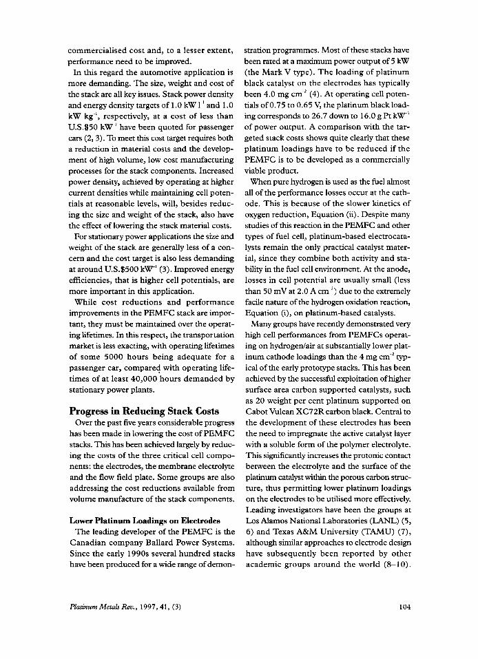
stration programmes. Most of these stacks have been rated at a maximum power output of 5 kW (the Mark V type). The loading of platinum black catalyst on the electrodes has typically been 4.0 mg cm-’ (4). At operating cell poten- tials of 0.75 to 0.65 V, the platinum black load- ing corresponds to 26.7 down to 16.0 g Pt k W ‘ of power output. A comparison with the tar- geted stack costs shows quite clearly that these platinum loadings have to be reduced if the PEMFC is to be developed as a commercially viable product.
When pure hydrogen is used as the fuel almost all of the performance losses occur at the cath- ode. This is because of the slower kinetics of oxygen reduction, Equation (ii). Despite many studies of this reaction in the PEh4FC and other types of fuel cell, platinum-based electrocata- lysts remain the only practical catalyst mater- ial, since they combine both activity and sta- bility in the fuel cell environment. At the anode, losses in cell potential are usually small (less than 50 mV at 2.0 A cm-2) due to the extremely facile nature of the hydrogen oxidation reaction, Equation (i), on platinum-based catalysts.
Many groups have recently demonstrated very high cell performances from PEMFCs operat- ing on hydrogedair at substantially lower plat- inum cathode loadings than the 4 mg cm-’ typ- ical of the early prototype stacks. This has been achieved by the successful exploitation of higher surface area carbon supported catalysts, such as 20 weight per cent platinum supported on Cabot Vulcan XC72R carbon black. Central to the development of these electrodes has been the need to impregnate the active catalyst layer with a soluble form of the polymer electrolyte. This significantly increases the protonic contact between the electrolyte and the surface of the platinum catalyst within the porous carbon struc- ture, thus permitting lower platinum loadings on the electrodes to be utilised more effectively. Leading investigators have been the groups at Los Alamos National Laboratories (LANL) (5, 6) and Texas A&M University (TAMU) (7), although similar approaches to electrode design have subsequently been reported by other academic groups around the world (8-10).
Platinum Metals Rev., 1997,41, (3) 104
Two basic approaches to electrodes have been developed by these groups.
At LANL thin film catalyst layers compris- ing the carbon supported catalyst mixed with the soluble form of the electrolyte (5 weight per cent Nafion" EW1100 in propan-2-01 and water) are deposited onto the membrane electrolyte. A microporous gas diffusion backing layer, employing a carbon cloth based electrode sub- strate, is compressed against the catalyst layer in the single cell to provide efficient removal of the product water from the cathode.
At TAMU the catalyst layer is first deposited onto the electrode support s t c u m e &om a mix- ture of carbon supported catalyst and polyte- trafluoroethylene (PTFE), which binds the layer together. Subsequently, the catalyst layer sur- face is impregnated with the membrane elec- trolyte solution.
Using these approaches LANL and TAMU have reported performances comparable to plat- inum black based cathodes, but with cathode catalyst loadings as low as 0.12 mg Pt cm-' and 0.05 mg Pt cm-2, respectively. Assuming a neg- ligible anode loading (reasonable for pure hydro- gen operation) the noble metal usage is reduced, from 13.4 down to 8.0 g Pt kW' for platinum black cathodes to less than 0.4 g Pt kW-' of power output at operating cell potentials of 0.75 to 0.65 V. Based on a platinum price of about U.S.312 g-', this represents a cost of less than U.S.35 k W ' for the noble metal, which is com- patible with all PEMFC applications.
Other methods of achieving high performance cathodes with low platinum loadings have been demonstrated. Notable is work by PSI Technol- ogy using cathodes formed from uncatalysed carbon black impregnated with a soluble form of the membrane electrolyte and then electro- deposited with platinum at loadings as low as 0.05 mg cm-2 (1 1). The aim of this approach was to deposit platinum only in regions of the electrode which were both in electronic contact with the carbon support and protonic contact with the membrane electrolyte, again ensuring efficient use of very low platinum loadings.
Other groups have deposited the platinum cat- alyst directly into the polymer membrane
electrolyte by chemical reduction of platinum salt solutions, see for instance (1 2). Loadings deposited in this way tend to be higher than with other methods (> 1 mg Pt cm-'). It appears that platinum can be isolated within the membrane in regions where it cannot be contacted elec- tronically. This, coupled with the much lower platinum dispersions achieved on the membrane, has meant that the effective catalyst surface areas are inferior to those in electrodes employing carbon supported platinum catalysts.
Electrodes Manufactured in Volume for Advanced Stack Designs
The above studies have largely been at the lab- oratory scale. Electrodes have been fabricated using manual techniques which do not neces- sarily lend themselves to scale-up to high vol- ume production and MEAs have been evalu- ated in small (< 50 cm2 active area) single cells. Cell performances have often been measured in cells functioning at high gas stoichiometries. This cannot be justified economically and per- formances can be raised on air operation, par- ticularly at higher current densities ( 1 3). In addi- tion, there have been few evaluations of operating lifetime data. Both LANL and TAMU are now, however, beginning to address these factors. LANL are examining the principle of ink jet printing the electrodes by modifying a chart recorder (1 4) and TAMU have investigated spraying and rolling the catalyst layers (1 5). Performances are being evaluated in larger sin- gle cells (50 to 100 cmz active area). The suc- cess in reducing the platinum loadings has led other academic and industrial groups to focus on mass production techniques suitable for elec- trodes and MEAs. However, testing has mostly been restricted to single cells, often with only 5 cm2 active area, see for example (1 6).
One major target of a joint programme between Ballard Power Systems and Johnson Matthey has been the development, for full size PEMFC stack hardware, of low platinum loading elec- trodes prepared in high volume. An electrode manufacturing process based on screen print- ing has been developed (17) and a small pilot plant facility has been established at Johnson
Platinum Metals Rev., 1997, 41, (3) 105

+ Unsupported Pt black MEA, e omg Ptcm-’ - LOW catalyst loading MEA. 062mg Ptcri’
Internal humidification
0.24 I 0 203 400 600 800 1000 1200 1400
CURRENT DENSITY, mA
Fig. 2 Cell potentiallcurrent density plots for high loading unsupported platinum black and low platinum loading carbon supported catalyst based MEAs. The membrane electrolyte was the experimental Dow XUS- 13204.10 material
Matthey. The plant currently produces around 50,000 electrodes per annum, but has the poten- tial for scaling-up as demand rises. Electrodes have been produced from inks comprising car- bon supported platinum catalysts and solutions of the polymer electrolyte. For high volume pro- duction it was deemed unsuitable to use the organic solutions of Nafion“ employed by LANL, TAMU and others to impregnate the catalyst (5-1 1). Besides not wanting to handle large vol- umes of organic solvents in a production envi- ronment, there is a possibility of interaction between the solvents and the high surface area platinum catalysts, which could result in the pro- duction of organic by-products in the inks and, with high solvent concentrations, possibly com- bustion. Thus, a method was developed to remove the alcohols from 5 weight per cent Nafion’ solution to give an essentially ‘aqueous’ Nafion” polymer solution (18), which has been used for routine manufacture of electrodes with catalyst loadings of 0.1 to 1 .O mg Pt cm-’.
Comparison of Electrodes Figure 2 shows the “beginning of life” cell
potential versus current density plot of a low catalyst loading MEA (0.62 mg Pt cm-’), com- pared with the higher loading unsupported plat- inum black MEA (8.0 mg Pt ern-') in a Ballard Mark V single cell of 240.2 cmz active area. The performances are comparable. The cathode comprises 40 weight per cent platinum on
Vulcan XC72R at a loading of 0.37 mg Pt cm-’ and the anode 20 weight per cent platinum-10 weight per cent ruthenium (Pt/Ru) on Vulcan XC72R at a loading of 0.25 mg Pt cm-’. At a cell potential of 0.75 to 0.65 V the MEA gen- erates 0.4 to 0.8 A ern-', equivalent to 0.3 to 0.5 W cm-’. This translates to a much reduced cat- alyst requirement of 2.0 down to 1.2 g Pt kW’ compared to 26.7 to 16.0 g Pt k W 1 for the plat- inum black MEA. This reduced loading shows considerable progress towards a platinum cat- alyst cost compatible with the stack cost targets for stationary and vehicle applications.
The “beginning of life” performances of the low platinum loading MEAs have been retained in the advanced Ballard stack technology being developed for submarine, bus, automotive and utility applications. With pure hydrogen fuel and air as oxidant, stable long term performance has been demonstrated in 4 and 8 cell sub-stacks and in full stacks. Figure 3 shows the perfor- mance of Dow membrane MEAs with anode and cathode catalyst loadings of 0.25 mg Pt cm-’ and 0.50 mg Pt cm-’, respectively, in an 8 cell stack representative of the Phase 2 bus stack hardware. This hardware is being developed for the forthcoming precommercial transit bus fleet trials in Chicago and Vancouver. Transit buses offer an early market opportunity for fuel cell power plants as cost targets are less demanding than for small vehicles and there is space to store sufEcient hydrogen fuel on-board to give a range
Platinum Metals Rev., 1997, 41, ( 3 ) 106
z W
P z W
P

6 Fig. 3 Durability of low platinum loading MEAs in an 8 cell Ballard stack, wing Dow XUS-13204.10 membrane > electrolyte. The stack J., construction is typical of the f hardware employed in the f) precommercial transit buses being supplied to Chicago and Vancouver
g a 4 z lJ
3
- Stack potential a t 0.646 A c m 2
t Stack potential at 1.076 A cm-*
I 200 400 600 BOO 1000 1200
TIME, hours
comparable to current diesel-fuelled engines. After 1000 hours at 0.646 A ern-', with 5-hour excursions to 1.076 A mi*, the degradation rate of below 4 pV h-' was well within target levels.
Reproducible Cell Performance Particularly important in volume manufacture
is reproducible performance. The low catalyst loading MEAS exhibit excellent cell to cell repro- ducibility in full stacks. In Figure 4 consistent
cell potentials produced by the individual cells in an 80 cell stack built for an air-independent submarine propulsion application are shown. The MEAs comprise cathodes with 0.6 mg Pt ern-', anodes with 0.25 mg Pt cm-' and Nafion" 1 17 membrane. The minimal variation in cell performance achieved over a range of current densities represents the highest level of cell to cell consistency that has recently been reported in the literature for PEMFC stacks, see for
0.2 4 I 0 10 20 30 4 0 50 60 70 80
NUMBER OF CELL
Fig. 4 Individual cell potentials in a full 80 cell stack for submarine propulsion. The low platinum loading MEAS contain Nafion" 117 membrane electrolyte. The high consistency of the cell potentials is a reflection of the control of operating conditions through the stack and the ability of the pilot plant at Johnson Matthey to manufacture reproducible electrodes. Uniformity in cell performance is of prime importance in the development of PEMFC technology
Platinum Metals Rev., 1997,41, (3) 107
z W
P
z W
P
z W
P

example the 50 cells in (19). This highlights the excellent degree of consistency achieved in MFL4 production and the efficient control of operat- ing conditions throughout the stack.
Based on the large volume of data now avail- able, it is clear that achieving economical plat- inum loadings on electrodes is no longer a bar- rier to the commercialisation of PEMFCs. The reduced metal loadings are clearly compatible with the cost targets for stationary power gen- eration and are close to the levels required for passenger cars. Indeed, rather than pursuing further cost reductions by lowering the elec- trode platinum loadings in stacks to the lowest levels studied in small cells (0.05 mg Pt cm-2), greater attention should be paid to improving cell performance at slightly higher, total MEA loadings (about 0.2 to 0.35 mg Pt cm-’ for auto- motive applications, and 0.5 to 1.0 mg Pt cm-* for stationary power plants). This would reduce the cost of all other stack materials and improve stack efficiencies.
Improved cell performance may be achieved by developing electrode structures in which the platinum catalyst is still more efficiently utilised. Even with the high performances discussed here, there are still performance losses due to oxygen and proton diffusion limitations in the electrode structures. Modelling and practical studies have indicated that even in the low platinum loading electrodes, only a limited thickness of the cat- alyst layer is being utilised. LANL have esti- mated this to be as little as 5 p in their struc- tures (20) and TAMU estimate a 10 pm thick active layer for their electrodes (2 1). While this suggests there is scope for maintaining perfor- mances as catalyst loadings are reduced - to the order of 0.1 mg Pt cm-’ and below - it also indicates enhanced performance is attainable.
Low Platinum Loading Anodes for Reformate Operation
There is no great technical challenge in low- ering platinum loadings on anodes operating with pure hydrogen fuel; anode catalyst load- ings as low as 0.025 mg Pt cm-’ are sufficient for high current density operation (22). However, for stationary power plant and light
duty vehicle applications, the anode fuel will almost certainly be impure hydrogen (refor- mate) produced via reforming carbon-contain- ing fuels, such as natural gas, methanol, petrol or diesel. Achieving satisfactory performance and durability with these fuels is much more difficult, because the anode is poisoned by trace levels of carbon monoxide present in the refor- mate. Carbon dioxide poisoning and dilution effects also reduce performance. But, even using impure hydrogen and with lowered anode plat- inum loadings the tolerance to poisoning has been increased. Unsupported platinum black catalyst has been replaced by higher surface area and more poison tolerant PtJRu catalyst sup- ported on Vulcan XC72R, and the catalyst has been impregnated with the soluble form of the polymer electrolyte to increase the number of active catalyst sites in the anode.
The favoured catalyst for tolerance to both carbon monoxide and carbon dioxide is PtJRu at 50:50 atomic per cent (23-25). Wilkinson and colleagues have confirmed that with PtJRu catalysts a higher catalyst dispersion and an increased protonic contact between the plat- inum and the membrane electrolyte improves the poison tolerance by increasing the number of non-poisoned catalyst sites within the anode (23). The best results have come from Iwase and Kawatsu, who showed that with Pt/Ru anodes containing 0.4 mg Pt cm-’ there is com- plete tolerance to 100 ppm carbon monoxide in hydrogen, at 80°C and 7 psig (24).
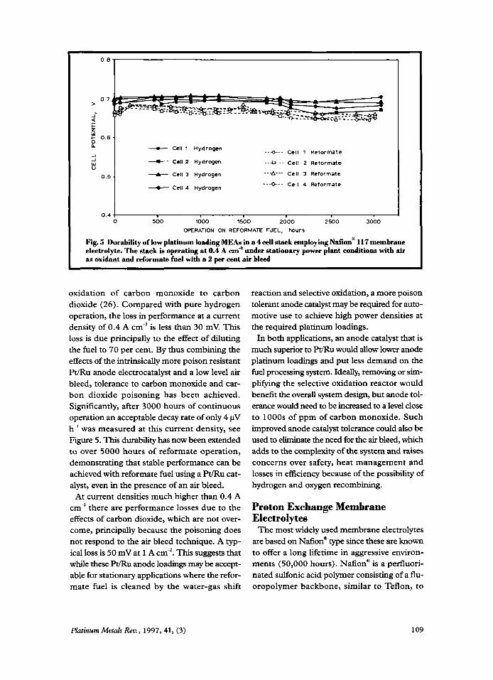
The long term performance of a 4 cell Ballard sub-stack, with Johnson MattheyBallard Power Systems low platinum loading MEAs is shown in Figure 5 . The MEAs contain PtJRu at 0.25 mg Pt cm-’ in the anode, Pt at 0.55 mg cm ’ on the cathode and Nafion” 117 membrane elec- trolyte. The stack is operating at a constant cur- rent density of 0.4 A cm-’ under typical sta- tionary power plant testing conditions. The oxidant is air and the reformate fuel contains 70 per cent hydrogen, 25 per cent carbon diox- ide and smaller quantities of other contami- nants, including 10 ppm carbon monoxide. A 2 per cent air bleed was also directly passed into the anode chamber to promote gas-phase
Platinum Metals Rev., 1997, 41, (3) 108
0 . 7
i 5
--Q--- Cell 1 Reformate - Cell 1 Hydrogen - Cell 2 Hydrogen - -O- - - Cell 2 Reformate
-A- Cell 3 Hydrogen --A- Cell 3 Reformate
---0-- Cell 4 Reformate --t Cell 4 Hydrogen
0.4 4 I 0 500 1000 1 5 0 0 2000 2500 3000
OPERATION ON REFORMATE FUEL, hours
Fig. 5 Durability of low platinum loading MEAs in a 4 cell stack employing Nafione 117 membrane electrolyte. The stack is operating at 0.4 A cm" under stationary power plant conditions with air as oxidant and reformate fuel with a 2 per cent air bleed
oxidation of carbon monoxide to carbon dioxide (26). Compared with pure hydrogen operation, the loss in performance at a current density of 0.4 A cm-' is less than 30 mV. This loss is due principally to the effect of diluting the fuel to 70 per cent. By thus combining the effects of the intrinsically more poison resistant Pt/Ru anode electrocatalyst and a low level air bleed, tolerance to carbon monoxide and car- bon dioxide poisoning has been achieved. Significantly, after 3000 hours of continuous operation an acceptable decay rate of only 4 pV h-' was measured at this current density, see Figure 5. This durability has now been extended to over 5000 hours of reformate operation, demonstrating that stable performance can be achieved with reformate fuel using a WRu cat- alyst, even in the presence of an air bleed.
At current densities much higher than 0.4 A cm-' there are performance losses due to the effects of carbon dioxide, which are not over- come, principally because the poisoning does not respond to the air bleed technique. A typ- ical loss is 50 mV at 1 A cm-'. This suggests that while these Pt/Ru anode loadings may be accept- able for stationary applications where the refor- mate fuel is cleaned by the water-gas shift
reaction and selective oxidation, a more poison tolerant anode catalyst may be required for auto- motive use to achieve high power densities at the required platinum loadings.
In both applications, an anode catalyst that is much superior to Pt/Ru would allow lower anode platinum loadings and put less demand on the fuel processing system. Ideally, removing or sim- plifying the selective oxidation reactor would benefit the overall system design, but anode tol- erance would need to be increased to a level close to 1000s of ppm of carbon monoxide. Such improved anode catalyst tolerance could also be used to eliminate the need for the air bleed, which adds. to the complexity of the system and raises concerns over safety, heat management and losses in efficiency because of the possibility of hydrogen and oxygen recombining.
Proton Exchange Membrane Electrolytes
The most widely used membrane electrolytes are based on Nafion@ type since these are known to offer a long lifetime in aggressive environ- ments (50,000 hours). Nafion' is a perfluori- nated sulfonic acid polymer consisting of a flu- oropolymer backbone, similar to Teflon, to
Plazinurn Metals Rew., 1997,41, (3) 109
z W
P
z W
P

which sulfonic acid groups are chemically bonded (27). The sulfonic acid groups are fixed in position, but the associated protons are free to provide conduction. These membranes are commercially available for around U.S.$ 700 m-’. Figure 6 shows the performances of a range of Nafion‘ membranes and of the experimen- tal Dow XUS-13204.10 membrane in a Ballard Mark V single cell. The electrodes, from Johnson Mattheymallard Power Systems, have low plat- inum loadings. The membrane resistance con- trols the single cell performance in the pseudo- linear region of the plot. The thinner Nafion’ membranes give enhanced performance par- ticularly at higher current densities (Nafion” 1 12 > Nafion’ 1 15 > Nafion’ 1 1 7) although the thinner membranes are less durable and more diacult to handle in mass production. The Dow membrane is close to the thickness of Nafion* 115, but gives superior performance due to a lower equivalent weight (defined as: gram of polymer/mole of sulfonic acid group).
Based on the superior performances of the Na60nY 1 12 and Dow membranes the electrolyte costs translate to about U.S.$ 135 k W ‘ at 0.65 V and U.S.$230 kW’ at 0.75 V, which is closer to the operating potential of a stationary power plant. This is perceived to be too costly, par- ticularly for widespread application of PEMFCs in passenger cars.
It has been quoted, however, that with an increase in demand of two orders of magnitude - a market of 1 million cars per year - mem- brane costs could be reduced by an order of magnitude (2). But, from a commercial view- point, it is likely that a range of products and suppliers will be necessary to drive the costs down, particularly to the levels required for auto- motive applications.
It is also likely that different membrane elec- trolytes will be employed in automotive and sta- tionary power plants. For stationary applica- tion, where 40,000 hours of operating lifetime is required but high power densities are less important, a thicker more durable membrane may be used, for instance a Nafion’ type mem- brane which, with cost reductions from volume demand and increased competition, could be
compatible with the cost target for this use, particularly with improved performance. In con- trast, a thinner higher power density membrane, which may be less durable than the perfluori- nated sulfonic acid membranes but have an oper- ating lifetime of 5,000 hours, will probably be used in passenger cars. Steck has reviewed stud- ies on preparing intrinsically lower cost mem- branes, many of which are hydrocarbon based or partially fluorinated (27). Most do not have the necessary stability or the low specific resis- tance shown by NafionR membranes.
New Ballard and Other Membranes Recently Ballard Advanced Materials have
developed a membrane material that is not fully fluorinated and which may be suitable for auto- motive applications (3, 27). The membrane shows at least equivalent “beginning of life” per- formance to the Dow XUS-13204.10 and Nafion’ 112 membranes in a Ballard Mark V single cell, Figure 6, (27). The Ballard mem- brane has demonstrated this performance for over 4500 hours - almost suficient for an auto- motive application (3). Since the preparation of this membrane is cheaper and since it produces more quantitative yields of partially fluorinated polymer, it is anticipated that with volume demand the membrane costs will be reduced to as little as U.S.$50 m-’. This translates to U.S.$ 10 kW-’ at 0.65 V and U.S.$ 17 k W ’ at 0.75 V with current performance levels, based on the low projected costs with volume demand.
In an alternative approach to preparing elec- trolytes for a wide range of applications, W. L. Gore & Associates have produced low platinum loading electrodes and MEAs based on very thin (5 to 40 pm) composite membranes, by impreg- nating a PTFE support with perfluorinated sul- fonic acid membrane electrolyte solution. The PTFE support is claimed to provide mechani- cal strength and dimensional stability in the thin membranes (28). Studies at LANL have shown that these Gore-SelectTM membranes give high performance both with LANL “thin film” elec- trodes and Gore’s own cathode, in small (5 cmz active area) single cells operating on hydrogen and air (28). The performance is not, however,
Platinum Metals Rm., 1997,41, (3) 110

1 0
> 0.8
i Q z W
0 06
-I 1 W U
0 4
0 2
t Nafion 117 178pm nominally
-s- Nation 115,127 pm nominally I
+ Nation 112, 51 prn nominally
-e- Dew, 125pm nominally
X EAM3G. taken from (27)
HI. air, 30 30psig, 15 20stoichiometry T C ~ I at 80-C
Internal humiditiutim
1 200 400 600 800 1000 1200 1.
CURRENT DENSITY, mA cn i ’
0
Fig. 6 Cell potentidcurrent density plots for a range of membrane electrolytes showing the importance of the membrane thickness and membrane type on performance
as high as projected for a homogeneous Nafione membrane of similar thickness, since the spe- cific resistance of the Gore membranes is higher. At 0.75 to 0.65 V, power densities of 0.3 to 0.5 W cm-’ are generated, similar to the power density produced by existing precommercial stacks. Potential cost savings are still available by using these thinner membrane materials. A material cost reduction to around U.S.$ 100 m-’ for a 20 pm thick membrane, based on the list price of the membrane electrolyte solution for the chloroalkali industry, has been quoted (29).
Recently, the performance of Gore MEAs was examined in a 50 cell stack manufactured by Energy Partners ( 19). The lower power density than observed in small single cells (0.24 W cm-’ at 0.6 V) was limited by a few cells. This was attributed to difficulty in controlling the water content in the MEAs resulting in flooding and gas diffusion limitations at the cathode.
Flow Field Plates The bipolar plate is the third high-cost com-
ponent in the fuel cell stack. The machined graphite flow field plates currently used are
estimated to account for as much as 60 per cent of present stack costs (29). As the plates are the heaviest and thickest stack components - and there are over two plates per MEA when addi- tional cooling and humidification plates are con- sidered - their replacement offers great poten- tial for reductions in stack size and weight. Two main approaches to fabricating flow field plates are being examined: thin metal plates and com- posite carbon plates; but there is little infor- mation in the literature as much of the work is industry led. While both approaches could lead to cheaper and lighter plates, there are prob- lems with maintaining low specific resistances in alternative materials. This will require much thinner plates to minimise ohmic potential losses, particularly for an automotive application.
Stainless steel plates have been examined by ECN (30) and LANL (14), and LANL have also investigated metal meshes; in general, cell poten- tials were lower due to higher contact resistances probably as a result of surface oxide films. LANL also noted that the cost of machining the metal plates was prohibitively high (1 4). Several com- panies are investigating the use of thin metallic
Platinum Metals Rev., 1997, 41, (3) 111
plates fabricated fkom a low cost base metal with a thin protective coating to provide the neces- sary stability to oxidation in the fuel cell envi- ronment. With such substrates it may be possi- ble to press or stamp out the flow fields.
The second approach is to fabricate moulded carbon black-polymer composite flow field plates. International Fuel Cells hold a patent on this concept (31). Thin, flexible graphite sheets with flow fields punched or stencilled in place have also been patented by Ballard (32, 33).
Remaining Technical Challenges and A Look Forward
While there has been considerable progress in recent years in reducing the stack costs, a num- ber of technical challenges remain. Improvements in performance are necessary to increase cell effi- ciency and power density at total MEA loadings of < 0.35 mg Pt cm-' for passenger cars and slightly higher for stationary power plants. At the cathode, improved oxygen reduction cata- lysts and improved cathode designs to utilise the platinum catalyst more fully are desirable. At the anode, besides greater utilisation of the catalyst in improved electrode designs, greater intrinsic catalyst tolerance to carbon monoxide and carbon dioxide is needed.
The development of membranes which can operate above 100°C would be of significant benefit in reducing carbon monoxide poison- ing, improving the electroche@cal kinetics and mass transport processes in the MEA, and allow- ing water removal in the vapour phase. A wider selection of membrane electrolytes from differ- ent suppliers is needed to reduce costs, partic- ularly for automotive use. Membranes with resis- tances lower than those of NafionO 1 12 or Dow XUS-13204.10, and with low gas transfer rates and durability of at least 5000 hours would clearly be beneficial for an automotive stack.
MEAs will have to be manufactured using high volume technology, and cheaper bipolar plate materials need to be developed. The resultant low cost MEAs and flow field plates then have to demonstrate the required operating lifetimes in the advanced stack hardware.
Among the stack ancillaries, the air delivery
sub-system is a major drain on power. Air com- pressors consume 10 to 15 per cent of the fuel cell output (2). Consequently there is a trade- off between improved stack performance at higher air pressures and the power required for compression. A low cost highly efficient air compressor is needed. In fact, many groups are developing electrodes, MEAs and stacks that function at ambient pressure (3), generally employing passive water and thermal manage- ment. Although small ambient pressure systems are attractive for low power applications it remains to be seen if compact ambient pressure systems can be developed for major multi-kilo- watt applications.
The recent progress in developing lower cost PEMFC stack components has created confi- dence that the remaining challenges can be suc- cessfully overcome. This view is supported by the increased attention being paid to fuelling and fuel infrastructure issues for vehicle appli- cations. While in the longer term the produc- tion of hydrogen fuel for PEMFCs from renew- able sources, such as solar energy, allied to the development of more efficient hydrogen stor- age materials is clearly desirable, early com- mercialisation will require hydrogen from fossil fuel sources. There is a major need to produce high performance, compact, fast start up, respon- sive, and fuel flexible, reformer systems, and Johnson Matthey, besides working to develop lower cost, higher performance catalysts, elec- trodes and MEAs, have produced a compact (0.25 1) autothermal reformer (Hotspot'") (34). This converts methanol selectively to hydrogen to produce a high output per unit volume - 2.5 kW of fuel cell power per litre of reactor - by a combination of steam reforming and par- tial oxidation. Heat transfer between the two reactions occurs over microscopic distances within the catalyst, avoiding the need for com- plicated heat-exchange engineering. Scale-up is achieved by feeding the appropriate number of individual reactors from a central manifold.
Thus all aspects of fuel cell development are under intensive investigation and with the sav- ings achieved in the key components successful commercialisation is much more certain.
Platinum Met& Rev., 1997, 41, (3) 112
References 1 D; S. Watkins, in “Fuel Cell Systems”, eds. L. J.
M. J. Blomen and M. N. Mugerwa, Plenum Press, New York, 1993, Chapter 1 1
2 C. E. Borroni-Bird,J. h e r Sources, 1996,61,33 3 K. Prater,J Power Sources, 1994, 51, 129 4 K. PraterJ Power Sources, 1990,29, 239 5 M. S. Wilson and S . Gottesfeld, J. Electrochem.
SOL., 1992, 139, L28 6 M. S. Wilson, J. A. Valerio and S. Gottesfeld,
Electrochim. Acta, 1995,40,355 7 C. Ferreira and S. Srinivasan, Extended Abstracts
Electrochemical Society Spring Meeting, San Francisco, 94-1, p. 969, The Electrochem. SOC., Pennington, New Jersey, 1994
8 G. Sasikumar, M. Raja and S. Parthasarathy, Electrochim. Acta, 1995,40, 285
9 P. G. Driven, W. J. Engelen and C. J. M. Van Der Poorten,J. Appl. Electrochem., 1995, 25, 122
10 M. Uchida, Y. Aoyama, N. Eda and A. Ohta, J. Electrochem. SOC., 1995,142,463
1 1 E. J. Taylor, E. B. Anderson and N. R K. Vilambi, J. Electrochem. Soc., 1992, 139, L45
12
13
14
15
16
17
P. Aldebert, F. Novel-Cattin, M. Pineri, P. Millet, C. Doumain and R. Durand, Solid State Zonics, 1989,35,3 T. R. Ralph, G. A. Hards, J. E. Keating, S. A. Campbell, D. P. Wilkinson, M. Davis, J. St-Pierre and M. C. Johnson, J. Electrochem. SOC., submit- ted for publication C. Zawodzinski, M. S. Wilson and S. Gottesfeld, Proc. First Int. Symp. on Proton Conducting Membrane Fuel Cells, eds. S. Gottesfeld, G. Halpert and A. Landgrebe, Vol. 95-23, p. 57, The Electrochem. SOC., Pennington, New Jersey, 1995 M. Wakizoe, 0. A. Velev and S. Srinivasan, Electrochim. Acta, 1995,40, 335 1 1 th World Hydrogen Energy Conference, 1996, 23-28th June, Stuttgart, reviewed by M. L. Doyle, Plannum Metals Rev., 1996,40, (4), 175 T. R. Ralph, G. A. Hards, D. Thompsett and J. M. Gascoyne, Extended Abstracts Fuel Cell Seminar, San Diego, 1994,199
18 J. Denton, J. M. Gascoyne and D. Thompsett, European Appl. 731,52OA, 1996
19 F. Barbir, F. Markin, B. Bahar and J. A. Kolde, Extended Abstracts Fuel Cell Seminar, Orlando, 1996,505
20 T. E. Springer, M. S. Wilson and S. Gottesfeld, J. Electrochem. SOC., 1993, 140,3513
21 E. A. Ticianelli, J. G. Berry and S. Srinivasan, J. Appl. Electrochem., 1991,21,597
22
23
24
25
26
27
28
29
30
31 32
33
G. A. Hards, T. R Ralph and S. J. Cooper, ETSU (of the UK DTI) Report No. ETSUIFCW002, “High Performance, Low Cost Membrane Electrode Assemblies for Solid Polymer Fuel Cells”, December 1992 D. P. Wilkinson, M. Bos, S. Knights, D. Thompsett, G. A. Hards and T. R. Ralph, to be published M. Iwase and S. Kawatsu, op.cit., (Ref. 14), Vol. 95-23, p. 12, The Electrochem. SOC., P e d g t o n , New Jersey, 1995 H. F. Oetjen, V. M. Schmidt, U. Stimming and F. Trila, 3. Electrochem. SOC., 1996, 143, 3838 S. Gottesfeld and J. Pafford, 3 Electrochem. SOC., 1988,135,2651 A. E. Steck, Proc. First International Symposium on New Materials For Fuel Cell Systems, Montreal, 1995,74 J. A. Kolde, B. Bahar, M. S. Wilson, T. A. Zawodzinski and S. Gottesfeld, op.cit., (Ref. 14), Vol. 95-23, p. 193, The Electrochem. SOC., Pennington, New Jersey, 1995 B. Bahar, Conference “Commercialising Fuel Cell Vehicles”, Chicago, 1996 R. K. A.M. Mallant, F. G. H. Koene, C. W. G. Verhoeve and A. Ruiter, Extended Abstracts Fuel Cell Seminar, San Diego, 1994, 503 R. J. Lawrence, US. Patent 4,214,969; 1980 D. P. Wilkinson, G. J. Lamont, H. H. Voss and C. Schwab, WorldAppl. 95/16287A; 1995 K. B. Washington, D. P. Wilkinson and H. H. Voss, US. Patenr 5,300,370; 1994
34 N. Edwards, S. R Ellis, J. C. Frost, S. E. Golunski, M. I. Petch and J. G. Reinkingh, European Fuel Cell News, 1996, 3, (2), 17
Platinum group metal complexes find exten- sive use as sensitisers, photocatalysts and photo- electrodes in harvesting sunlight to produce elec- tricity or hydrogen by the electrolysis of water (1). Hydrogen is usually photoproduced from water using semiconductors and catalysts, and polymer semiconductors combined with ruthe- nium chloride can produce hydrogen effectively.
Now scientists from the Tokyo Institute of Technology (2) report a photocatalytic system which produces hydrogen from the electroly- sis of water using a semiconducting chelating n-conjugated polymer poly(2,2‘-bipyridine-5,5’- diyl), which has a strong affinity towards metals,
Platinum Increases Hydrogen Photoproduction and [Pt(bpy)~] (NO& (bpy = 2,2‘-bipyridyl) as photocatalyst in aqueous NEt3 solution.
When irradiated with light, the system pro- duced hydrogen with a turnover number of &:[Pt(bpy)$’ of 490 and maintained this acuv- ity over several cycles. This is thought to be related to the ability of the polymer to trap plat- inum as [Pt(bpy)]’+ on its surface.
1 Referencea
M. Gratzel, Platinum Metals Rev., 1994, 38, (4), 151; M. LDoyle,PlatinumMetaLF Rev., 1996,40,
T. Maruyama and T. Yamamoto, J. Phys. Chem. B, 1997, 101, (19), 3806
(413 175 2
Platinum Metals Rev., 1997,41, (3) 113