Protocol API - ftp.ruigongye.comftp.ruigongye.com/200802/2008051911153100001.pdf ·...
132
www.hilscher.com Protocol API DeviceNet-Master Language: English
Transcript of Protocol API - ftp.ruigongye.comftp.ruigongye.com/200802/2008051911153100001.pdf ·...
www.hilscher.com
Protocol API
DeviceNet-Master
Language: English

DeviceNet-Master • 2
_________________________________________________________________________________ Hilscher Gesellschaft für Systemautomation mbH – Rheinstr. 15 – D-65795 Hattersheim
Edition 1 – API:DeviceNet-Master#EN– 2008/03
Revision History
Rev Date Name Revisions
1 04.03.08 RG Created
Firmware/ stack version V0.9.0
DeviceNet-Master • 3
_________________________________________________________________________________ Hilscher Gesellschaft für Systemautomation mbH – Rheinstr. 15 – D-65795 Hattersheim
Edition 1 – API:DeviceNet-Master#EN– 2008/03
All rights reserved. No part of this publication may be reproduced.
The Author makes no warranty of any kind with regard to this material, including but not limited to the implied warranties of merchantability and fitness for a particular purpose. The Author assumes also no responsibility for any errors that may appear in this document.
Although this software has been developed with great care and was intensively tested, Hilscher Gesellschaft für Systemautomation mbH cannot guarantee the suitability of this software for any purpose not confirmed by us in written form. Guarantee claims shall be limited to the right to require rectification. Liability for any damages which may have arisen from the use of this software or its documentation shall be limited to cases of intent. We reserve the right to modify our products and their specifications at any time in as far as this contribute to technical progress. The version of the manual supplied with the software applies.
Please notice: Windows 95/98/ME and Windows NT/2000/CE/XP/Vista are registered trademarks of Microsoft Corporation.
DeviceNet-Master • 4
_________________________________________________________________________________ Hilscher Gesellschaft für Systemautomation mbH – Rheinstr. 15 – D-65795 Hattersheim
Edition 1 – API:DeviceNet-Master#EN– 2008/03
Table of Contents
1 Introduction....................................................................................................................................9 1.1 Abstract ...................................................................................................................................... 9 1.2 Intended Audience ..................................................................................................................... 9 1.3 System Requirements ................................................................................................................ 9 1.4 Specifications ........................................................................................................................... 10
1.4.1 Technical Data ............................................................................................................................... 10 1.4.2 Object Modeling ............................................................................................................................. 11
1.5 Terms, Abbreviations and Definitions ...................................................................................... 15 1.6 References ............................................................................................................................... 15
2 Fundamentals ..............................................................................................................................16 2.1 General Access Mechanisms on netX Systems ...................................................................... 16 2.2 Accessing the Protocol Stack by Programming the AP Task’s Queue.................................... 17
2.2.1 Getting the Receiver Task Handle of the Process Queue.............................................................. 17 2.2.2 Meaning of Source- and Destination-related Parameters .............................................................. 17
2.3 Accessing the Protocol Stack via the Dual Port Memory Interface.......................................... 18 2.3.1 Communication via Mailboxes ....................................................................................................... 18 2.3.2 Using Source and Destination Variables correctly ......................................................................... 19 2.3.3 Obtaining useful Information about the Communication Channel .................................................. 22
2.4 Client/Server Mechanism ......................................................................................................... 24 2.4.1 Application as Client....................................................................................................................... 24 2.4.2 Application as Server ..................................................................................................................... 25
3 Dual-Port Memory........................................................................................................................26 3.1 Cyclic Data (Input/Output Data) ............................................................................................... 26
3.1.1 Input Process Data......................................................................................................................... 27 3.1.2 Output Process Data...................................................................................................................... 27
3.2 Acyclic Data (Mailboxes) .......................................................................................................... 28 3.2.1 General Structure of Messages or Packets for Non-Cyclic Data Exchange................................... 29 3.2.2 Status & Error Codes ..................................................................................................................... 32 3.2.3 Differences between System and Channel Mailboxes ................................................................... 32 3.2.4 Send Mailbox ................................................................................................................................. 33 3.2.5 Receive Mailbox............................................................................................................................. 33 3.2.6 Channel Mailboxes (Details of Send and Receive Mailboxes) ....................................................... 33
3.3 Status ....................................................................................................................................... 34 3.3.1 Common Status ............................................................................................................................. 34 3.3.2 Extended Status............................................................................................................................. 43
3.4 Control Block ............................................................................................................................ 54 4 Getting started / Configuration ..................................................................................................55
4.1 Overview about Essential Functionality ................................................................................... 55 4.2 Configuration of Bus, Slave, Server and Device Parameters .................................................. 56
4.2.1 Write Access to the Dual-Port Memory .......................................................................................... 56 4.2.2 Using the configuration tool SYCON.NET...................................................................................... 56
4.3 Detailed Description of DeviceNet Configuration Parameters ................................................. 57 4.3.1 Detailed Description of Bus Parameters ........................................................................................ 57 4.3.2 Detailed Description of Slave Parameters...................................................................................... 60 4.3.3 Detailed Description of Device Parameters.................................................................................... 60 4.3.4 Detailed Description of Server Parameters .................................................................................... 63
5 The DeviceNet Application Interface .........................................................................................64 5.1 The DevNet AP - Task ............................................................................................................. 64
5.1.1 Handled Commands ...................................................................................................................... 65 5.1.2 Extended Status Information.......................................................................................................... 66
5.2 The DevNet FAL - Task............................................................................................................ 66 5.2.1 DEVNET_FAL_CMD_INIT_REQ/CNF – Initialize the DeviceNet Stack.......................................... 67 5.2.2 DEVNET_FAL_CMD_SET_MODE_REQ/CNF – Set DeviceNet Operation Mode .............................. 71 5.2.3 DEVNET_FAL_CMD_DOWNLOAD_REQ/CNF – Download DeviceNet Configuration........................ 76 5.2.4 DEVNET_FAL_CMD_GET_ATT_REQ/CNF – Get Attribute Request ............................................... 98 5.2.5 DEVNET_FAL_CMD_SET_ATT_REQ/CNF – Set Attribute Request.............................................. 105 5.2.6 DEVNET_FAL_CMD_ACYC_BTS_REQ/CNF – Acyclic Bit-Strobing................................................ 110

DeviceNet-Master • 5
_________________________________________________________________________________ Hilscher Gesellschaft für Systemautomation mbH – Rheinstr. 15 – D-65795 Hattersheim
Edition 1 – API:DeviceNet-Master#EN– 2008/03
5.2.7 DEVNET_FAL_CMD_LIFELIST_REQ/CNF – Generate Lifelist..................................................... 115 5.2.8 DEVNET_FAL_CMD_UPLOAD_REQ/CNF –Parameter Upload....................................................... 118 5.2.9 DEVNET_FAL_CMD_FAULT_IND/RES – Indication of a Fault...................................................... 122
5.3 The CAN DL - Task ................................................................................................................ 125 6 Status/Error Codes Overview...................................................................................................126
6.1 Status/Error Codes DevNet AP - Task................................................................................... 127 6.2 Status/Error Codes DevNet FAL - Task ................................................................................. 128 6.3 Status/Error Codes CAN DL - Task ....................................................................................... 131
7 Contact........................................................................................................................................132
DeviceNet-Master • 6
_________________________________________________________________________________ Hilscher Gesellschaft für Systemautomation mbH – Rheinstr. 15 – D-65795 Hattersheim
Edition 1 – API:DeviceNet-Master#EN– 2008/03
List of Figures Figure 1 - The three different Ways to access a Protocol Stack running on a netX System .................................. 16 Figure 2 - Use of ulDest in Channel and System Mailbox ................................................................................... 19 Figure 3 - Using ulSrc and ulSrcId................................................................................................................... 20 Figure 4: Transition Chart Application as Client ..................................................................................................... 24 Figure 5: Transition Chart Application as Server.................................................................................................... 25

DeviceNet-Master • 7
_________________________________________________________________________________ Hilscher Gesellschaft für Systemautomation mbH – Rheinstr. 15 – D-65795 Hattersheim
Edition 1 – API:DeviceNet-Master#EN– 2008/03
List of Tables Table 1: Identity Object Supported Features ......................................................................................................... 11 Table 2: DeviceNet Object Supported Features..................................................................................................... 12 Table 3: Connection Object Supported Features ................................................................................................... 13 Table 4: Acknowledge Handler Object Supported Features ................................................................................. 14 Table 5: Terms, abbreviations and definitions ....................................................................................................... 15 Table 6: References............................................................................................................................................... 15 Table 7: Names of Queues in Device Net Firmware .............................................................................................. 17 Table 8: Meaning of Source- and Destination-related Parameters. ....................................................................... 17 Table 9: Meaning of Destination-Parameter ulDest.Parameters. ........................................................................... 19 Table 10: Example for correct Use of Source- and Destination-related Parameters.:............................................ 21 Table 11: Address Assignment of Hardware Assembly Options............................................................................ 22 Table 12: Addressing Communication Channel 0-3............................................................................................... 23 Table 13: Address Assignment of Communication Channels demonstrated at Communication Channel 0 .......... 23 Table 14: Input Data Image ................................................................................................................................... 27 Table 15: Output Data Image................................................................................................................................. 27 Table 16: General Structure of Packets for non-cyclic Data Exchange.................................................................. 29 Table 17: Status and Error Codes.......................................................................................................................... 32 Table 18: Channel Mailboxes. ............................................................................................................................... 33 Table 19: Common Status Block............................................................................................................................ 35 Table 20: Master Status Structure Definition ......................................................................................................... 40 Table 21: Status and Error Codes.......................................................................................................................... 41 Table 22: Extended Status Block for DeviceNet-Master ........................................................................................ 44 Table 23: Contents of Global Bits Variable ............................................................................................................ 44 Table 24: Error Types in Global Bits ...................................................................................................................... 45 Table 25: Operation Modes of the DeviceNet-Master and their Values ................................................................. 46 Table 26: Relationship between Slave Device MAC ID and the corresponding abDv_cfg_active[8] Bit ........ 47 Table 27: Relationship between Slave Device MAC ID and the corresponding abDv_cfg_inactive[8] Bit .... 47 Table 28: Relationship between Slave Device MAC ID and the corresponding abDv_state_expl[8] Bit ........ 48 Table 29: Relationship between Slave Device MAC ID and the corresponding abDv_State_io[8] Bit ............ 48 Table 30: Relationship between Slave Device MAC ID and the corresponding abDv_diag Bit ........................... 49 Table 31: Relationship between abDv_State_IO bit and abDv_Diag bit ........................................................... 49 Table 32: Errors which may occur in the Network (bErr_device_adr is equal to 255) ...................................... 50 Table 33: Errors which may occur in the DeviceNet-Master Device (bErr_Rem_Adr is not equal to 255) ........... 53 Table 34: Communication Control Block................................................................................................................ 54 Table 35: Overview about Essential Functionality (Cyclic and acyclic Data Transfer and Alarm Handling)........... 55 Table 36: Slave Parameters, their Meanings and their Ranges of allowed Values................................................ 58 Table 37: Available Baud Rate Values................................................................................................................... 58 Table 38: Meaning of Bus Parameter Configuration Flags Byte ............................................................................ 59 Table 39: Meaning of Auto Clear Bit ...................................................................................................................... 59 Table 40: Device Parameters, their Meanings and their Ranges of allowed Values .............................................. 60 Table 41: Meaning of EnableFlags Byte ................................................................................................................ 61 Table 42: Slave Parameters, their Meanings and their Ranges of allowed Values................................................ 63 Table 43: DevNetAP-Task Process Queue............................................................................................................ 64 Table 44: DeviceNet-Master - Handled Commands............................................................................................... 65 Table 45: DevNetFAL-Task Process Queue.......................................................................................................... 66 Table 46: DN_FAL_CMD_INIT_REQ – Request Command for DN Init .................................................................. 67 Table 47: DEVNET_FAL_CMD_INIT_CNF – Confirmation of Init Request ............................................................. 69 Table 48: DEVNET_FAL_CMD_INIT_CNF – Packet Status/Error........................................................................... 70 Table 49: DEVNET_FAL_CMD_SET_MODE_REQ – Request Command for setting the DevNet Operation Mode .... 72 Table 50: DEVNET_FAL_CMD_SET_MODE_CNF – Confirmation of DN Set Mode Command................................. 74 Table 51: DEVNET_FAL_CMD_SET_MODE_CNF – Packet Status/Error .................................................................. 75 Table 52: DEVNET_FAL_CMD_DOWNLOAD_REQ – Request Command for Configuration Download ..................... 77 Table 53: DEVNET_FAL_CMD_DOWNLOAD_CNF – Confirmation of Configuration Download.................................. 80 Table 54: DEVNET_FAL_CMD_DOWNLOAD_CNF – Packet Status/Error .................................................................. 82 Table 55: Device Parameter Structure................................................................................................................... 83 Table 56: Flags within ulEnableFlags .................................................................................................................... 84 Table 57: Server Parameter Structure ................................................................................................................... 85 Table 58: Slave Parameter Structure..................................................................................................................... 88 Table 59: bDevFlag................................................................................................................................................ 88 Table 60: Additional Header Structures ................................................................................................................. 89 Table 61: Example for IO_Modules table............................................................................................................... 91 Table 62: Structure of DN_PRED_MSTSL_ADD_TAB_T .......................................................................................... 92 Table 63: Structure of IO_Offsets .......................................................................................................................... 93
DeviceNet-Master Introduction • 8
_________________________________________________________________________________ Hilscher Gesellschaft für Systemautomation mbH – Rheinstr. 15 – D-65795 Hattersheim
Edition 1 – API:DeviceNet-Master#EN– 2008/03
Table 64: Structure of DN_PRE_MSTSL_ADD_TAB_T ............................................................................................ 93 Table 65: Structure of DN_SET_ATTR_DATA_T ..................................................................................................... 94 Table 66: Example for DN_EXPL_SET_ATTR_DATA_T.......................................................................................... 94 Table 67: Bus Parameter Structure........................................................................................................................ 96 Table 68: System Flags ......................................................................................................................................... 96 Table 69: Configuration Flags................................................................................................................................ 97 Table 70: DEVNET_FAL_CMD_GET_ATT_REQ - Get Attribute Request.................................................................. 99 Table 71: DEVNET_FAL_CMD_GET_ATT_CNF - Confirmation of Get Attribute Request ...................................... 102 Table 72: DEVNET_FAL_CMD_GET_ATT_CNF – Packet Status/Error .................................................................. 103 Table 73: Generic Error (Variable bGenErr) ........................................................................................................ 104 Table 74: Additional Error (Variable bAddErr)...................................................................................................... 104 Table 75: DEVNET_FAL_CMD_SET_ATT_REQ - Set Attribute Request ................................................................ 106 Table 76: DEVNET_FAL_CMD_SET_ATT_REQ - Confirmation of Set Attribute Request....................................... 108 Table 77: DEVNET_FAL_CMD_SET_ATT_ CNF_T – Packet Status/Error............................................................ 109 Table 78: Assignment Table for Bits in Master Scan List and associated MAC IDs of DeviceNet Slaves ........... 111 Table 79: DEVNET_FAL_CMD_ACYC_BTS_REQ – Acyclic Bit-Strobing ................................................................ 112 Table 80: DEVNET_FAL_CMD_ACYC_BTS_REQ - Packet Status/Error ................................................................. 112 Table 81: DEVNET_FAL_CMD_ACYC_BTS_CNF – Confirmation of Acyclic Bit-Strobing ....................................... 113 Table 82: DEVNET_FAL_CMD_ACYC_BTS_CNF - Packet Status/Error ................................................................. 114 Table 83: Status Bytes in Lifelist .......................................................................................................................... 115 Table 84: DEVNET_FAL_CMD_LIFELIST_REQ – Generate Lifelist................................................................... 116 Table 85: DEVNET_FAL_CMD_LIFELIST_REQ – Packet Status/Error.............................................................. 116 Table 86: DEVNET_FAL_CMD_LIFELIST_CNF – Confirmation of Generate Lifelist............................................ 117 Table 87: DEVNET_FAL_CMD_LIFELIST_CNF – Packet Status/Error ................................................................ 117 Table 88: DEVNET_FAL_CMD_UPLOAD_REQ - Parameter Upload ....................................................................... 119 Table 89: DEVNET_FAL_CMD_UPLOAD_REQ - Packet Status/Error ..................................................................... 119 Table 90: DEVNET_FAL_CMD_UPLOAD_CNF – Confirmation of Upload............................................................... 121 Table 91: DEVNET_FAL_CMD_UPLOAD_CNF - Packet Status/Error ..................................................................... 121 Table 92: DEVNET_FAL_CMD_FAULT_IND - Indication of a Fault ....................................................................... 122 Table 93: DEVNET_FAL_CMD_FAULT_IND - Packet Status/Error ....................................................................... 123 Table 94: DEVNET_FAL_CMD_FAULT_RES – Response to Indication of a Fault ................................................. 124 Table 95: DEVNET_FAL_CMD_FAULT_RES - Packet Status/Error ....................................................................... 124 Table 96: Header Files containing Status/Error Codes ........................................................................................ 126 Table 97: Status/Error Codes DevNet AP - Task ................................................................................................. 127 Table 98: Status/Error Codes DevNet FAL - Task ............................................................................................... 130 Table 99: Status/Error Codes CAN DL - Task...................................................................................................... 131

DeviceNet-Master Introduction • 9
_________________________________________________________________________________ Hilscher Gesellschaft für Systemautomation mbH – Rheinstr. 15 – D-65795 Hattersheim
Edition 1 – API:DeviceNet-Master#EN– 2008/03
1 Introduction
1.1 Abstract This manual describes the application interface of the DeviceNet-Master Stack. The aim of this manual is to support the developer during the integration process of the given stack into a user application.
This protocol stack is based on the Hilscher Task Layer Reference Programming Model. It is a description of how to program a task in general, which is defined as a combination of appropriate functions belonging to the same type of protocol layer. It furthermore defines how different tasks have to communicate with each other in order to exchange their layer information in between. The Reference Model is commonly used by all Programmers at Hilscher and shall be used by you as well when writing your Application Task on top of the Stack.
1.2 Intended Audience This manual is suitable for software developers with the following background:
Knowledge of the programming language C
Knowledge of the use of the real-time operating system rcX
Knowledge of the Hilscher Task Layer Reference Model
1.3 System Requirements This software package has the following system requirements:
netX-Chip as CPU hardware platform
Operating system for task scheduling required
Operating system rcX

DeviceNet-Master Introduction • 10
_________________________________________________________________________________ Hilscher Gesellschaft für Systemautomation mbH – Rheinstr. 15 – D-65795 Hattersheim
Edition 1 – API:DeviceNet-Master#EN– 2008/03
1.4 Specifications
1.4.1 Technical Data
The data below applies to DeviceNet Master firmware and stack version 0.9.0
Maximum number of cyclic input data 3584 bytes
Maximum number of cyclic output data 3584 bytes
Maximum number of cyclic input data 255 bytes/connection
Maximum number of cyclic output data 255 bytes/connection
Maximum number of supported slaves 63
Maximum Configuration data 1000 bytes/slave
Acyclic communication Explicit connection Get_Attribute_Single/All Set_Attribute_Single/All
Baud rates 125 kBits/s, 250 kBit/s, 500 kBit/s Auto-detection mode is not supported.
Data transport layer CAN frames
Connections Bit Strobe Change of State Cyclic Poll Explicit Peer-to-Peer Messaging
Fragmentation Explicit and I/O
UCMM supported
Support common and extended diagnostic
Objects Identity Object (Class Code 0x01) Message Router Object (Class Code 0x02) DeviceNet Object (Class Code 0x03) Connection Object (Class Code 0x05) Acknowledge Handler Object (Class Code 0x06)
Firmware/stack available for netX
netX 50 no
netX 100, netX 500 yes
Configuration
Configuration by tool SYCON.net (Download or exported configuration file named config.nxd).
Configuration by packets to transfer bus and node parameters.
DeviceNet-Master Introduction • 11
_________________________________________________________________________________ Hilscher Gesellschaft für Systemautomation mbH – Rheinstr. 15 – D-65795 Hattersheim
Edition 1 – API:DeviceNet-Master#EN– 2008/03
Diagnostic
Firmware supports common and extended diagnostic in the dual-port-memory for loadable firmware.
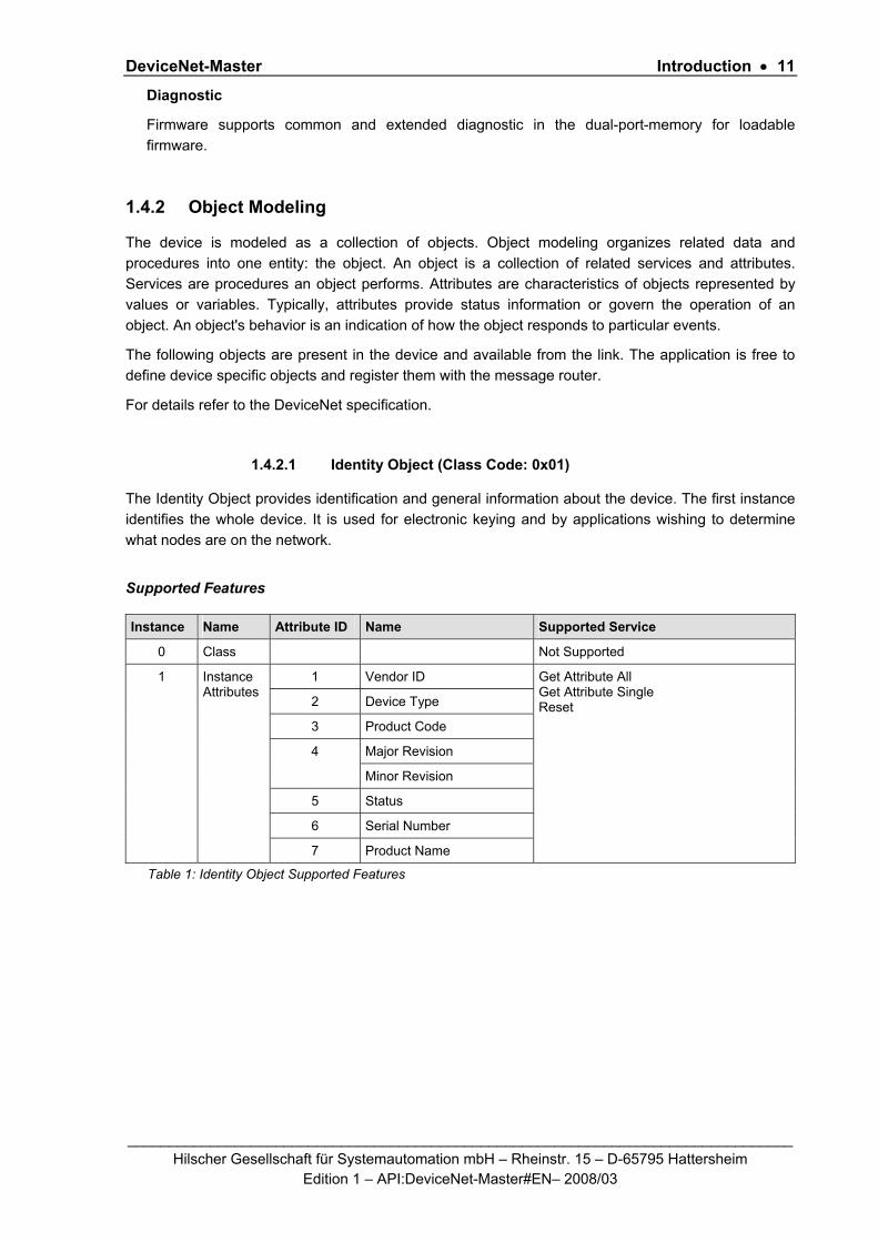
1.4.2 Object Modeling
The device is modeled as a collection of objects. Object modeling organizes related data and procedures into one entity: the object. An object is a collection of related services and attributes. Services are procedures an object performs. Attributes are characteristics of objects represented by values or variables. Typically, attributes provide status information or govern the operation of an object. An object's behavior is an indication of how the object responds to particular events.
The following objects are present in the device and available from the link. The application is free to define device specific objects and register them with the message router.
For details refer to the DeviceNet specification.
1.4.2.1 Identity Object (Class Code: 0x01)
The Identity Object provides identification and general information about the device. The first instance identifies the whole device. It is used for electronic keying and by applications wishing to determine what nodes are on the network.
Supported Features
Instance Name Attribute ID Name Supported Service
0 Class Not Supported
1 Vendor ID
2 Device Type
3 Product Code
Major Revision 4
Minor Revision
5 Status
6 Serial Number
1 Instance Attributes
7 Product Name
Get Attribute All Get Attribute Single Reset
Table 1: Identity Object Supported Features

DeviceNet-Master Introduction • 12
_________________________________________________________________________________ Hilscher Gesellschaft für Systemautomation mbH – Rheinstr. 15 – D-65795 Hattersheim
Edition 1 – API:DeviceNet-Master#EN– 2008/03
1.4.2.2 Message Router Object (Class Code: 0x02)
The Message Router Object provides a messaging connection point through which a client may address a service to any object class or instance residing in the physical device.
Supported Features
There are no services supported by the Message Router Object.
1.4.2.3 DeviceNet Object (Class Code: 0x03)
The DeviceNet Object contains information about the configured DeviceNet Slave. Examples of this information include MAC ID, Baud rate, etc. as shown below. This object only supports Get Attribute Single and Set Attribute Single.
Supported Features
Instance Name Attribute ID Name Supported Service
0 Class 1 Revision Get Attribute Single
1 MAC ID
2 Baudrate
3 Bus Off Interrupts
4 Bus Off Counter
1 Instance Attributes
5 Object Allocation Information
Get Attribute Single Set Attribute Single
Table 2: DeviceNet Object Supported Features

DeviceNet-Master Introduction • 13
_________________________________________________________________________________ Hilscher Gesellschaft für Systemautomation mbH – Rheinstr. 15 – D-65795 Hattersheim
Edition 1 – API:DeviceNet-Master#EN– 2008/03
1.4.2.4 Connection Object (Class Code: 0x05)
The Connection Object consists of multiple objects which provide information about the current connection status. Each instance relates to a different connection type. For example Explicit Messaging connection, Bit Strobe, Polled, and Change of State.
Supported Features
Instance Name Attribute ID
Name Supported Service
0 Class 1 Revision Not Supported
1 Connection State
2 Connection Type
3 Transport Type
4 Produced Connection ID
5 Consumed Connection ID
6 Initial Com Characteristics
7 Produced Connection Size
8 Consumed Connection Size
9 Expected Packet Rate
12 Timeout Action
13 Produced Path Length
14 Produced Connection Path ID
15 Consumed Path Length
16 Consumed Connection Path ID
1 Instance Attributes
Explicit Messaging Connection
17 Inhibit Time
Get Attribute Single Set Attribute Single
2 Polled Connection
1- 17 As Above.
3 Bit Strobe Connection
1 - 17 As Above.
4 Change of State Connection
1 - 17 As Above.
Table 3: Connection Object Supported Features

DeviceNet-Master Introduction • 14
_________________________________________________________________________________ Hilscher Gesellschaft für Systemautomation mbH – Rheinstr. 15 – D-65795 Hattersheim
Edition 1 – API:DeviceNet-Master#EN– 2008/03
1.4.2.5 Acknowledge Handler Object (Class Code: 0x06)
The Acknowledge Handler Object is responsible for handling acknowledge response messages from the slave. This object supports both Get and Set Attribute Single. Attributes supported are shown below.
Supported Features
Instance Name Attribute ID Name Supported Service
0 Class Not Supported
1 Acknowledge Timer
2 Acknowledge Handler Retry Limit
3 COS Produced ID
1 Instance Attributes
Get Attribute Single Set Attribute Single
Table 4: Acknowledge Handler Object Supported Features

DeviceNet-Master Introduction • 15
_________________________________________________________________________________ Hilscher Gesellschaft für Systemautomation mbH – Rheinstr. 15 – D-65795 Hattersheim
Edition 1 – API:DeviceNet-Master#EN– 2008/03
1.5 Terms, Abbreviations and Definitions Term Description
AP Application on top of the Stack
API Application Programmer Interface
AREP Application Reference End Point
DN DeviceNet
DNM DeviceNet Master
DNS DeviceNet Slave
DN_FAL DeviceNet Fieldbus Application Layer (abstract designation for the DeviceNet Stack)
DPM Dual Port Memory
FAL Fieldbus Application Layer (abstract designation for a Fieldbus layer)
MAC ID Media Access Control Identifier
SDU Service Data Unit
Table 5: Terms, abbreviations and definitions
All variables, parameters and data used in this manual have basically the LSB/MSB (“Intel”) data representation. This corresponds to the convention of the Microsoft C Compiler.
1.6 References This document is based on the following specifications:
1 Task Layer Reference Manual, Hilscher GmbH
2 netX DPM Interface Manual, Hilscher GmbH
3 The CIP Networks Library, Volume 1, “Common Industrial Protocol (CIP™)”, Edition 3.2
4 The CIP Networks Library, Volume 2, “DeviceNet Adaptation of CIP”, Edition 1.4
Table 6: References

DeviceNet-Master Fundamentals • 16
_________________________________________________________________________________ Hilscher Gesellschaft für Systemautomation mbH – Rheinstr. 15 – D-65795 Hattersheim
Edition 1 – API:DeviceNet-Master#EN– 2008/03
2 Fundamentals
2.1 General Access Mechanisms on netX Systems This chapter explains the possible ways to access a Protocol Stack running on a netX system :
1. By accessing the Dual Port Memory Interface directly or via a driver.
2. By accessing the Dual Port Memory Interface via a shared memory.
3. By interfacing with the Stack Task of the Protocol Stack.
The picture below visualizes these three ways:
(Extended) Status Block Send Mailbox Reveive Mailbox Output Data Image Input Data Image
Network Abstraction Layer
Fieldbus Task(s)
Network
AP Task
1
3
2
Figure 1 - The three different Ways to access a Protocol Stack running on a netX System
This chapter explains how to program the stack (alternative 3) correctly while the next chapter describes accessing the protocol stack via the dual-port memory interface according to alternative 1 (and 2, if the user application is executed on the netX chip in the context of the rcX operating system and uses the shared DPM). Finally, chapter 5 titled “The DeviceNet Application Interface” describes the entire interface to the protocol stack in detail.
Depending on whether you choose the stack-oriented approach or the Dual Port Memory-based approach, you will need either the information given in this chapter or those of the next chapter to be able to work with the set of functions described in chapter 5. All of those functions use the four parameters ulDest, ulSrc, ulDestId and ulSrcId. This chapter and the next one inform about how to work with these important parameters.

DeviceNet-Master Fundamentals • 17
_________________________________________________________________________________ Hilscher Gesellschaft für Systemautomation mbH – Rheinstr. 15 – D-65795 Hattersheim
Edition 1 – API:DeviceNet-Master#EN– 2008/03
2.2 Accessing the Protocol Stack by Programming the AP Task’s Queue In general, programming the AP task or the stack has to be performed according to the rules explained in the Hilscher Task Layer Reference Manual. There you can also find more information about the variables discussed in the following.
2.2.1 Getting the Receiver Task Handle of the Process Queue
To get the handle of the process queue of the DeviceNetAP-Task or the DeviceNet FAL -Task the Macro TLR_QUE_IDENTIFY() needs to be used. It is described in detail within section 10.1.9.3 of the Hilscher Task Layer Reference Model Manual. This macro delivers a pointer to the handle of the intended queue to be accessed (which is returned within the third parameter, phQue), if you provide it with the name of the queue (and an instance of your own task). The correct ASCII-queue names for accessing the DeviceNetAP -Task or the DeviceNet FAL -Task, which you have to use as current value for the first parameter (pszIdn), is
ASCII Queue name Description
"QUE_DEVNET_AP” Name of the DeviceNet Application-Task process queue
"DEVNET_FAL_QUE” Name of the DeviceNet Field Application Layer-Task process queueTable 7: Names of Queues in Device Net Firmware
The returned handle has to be used as value ulDest in all initiator packets the AP-Task intends to send to the EipObject-Task . This handle is the same handle that has to be used in conjunction with the macros like TLR_QUE_SENDPACKET_FIFO/LIFO() for sending a packet to the respective task.
2.2.2 Meaning of Source- and Destination-related Parameters The meaning of the source- and destination-related parameters is explained in the following table:
Variable Meaning
ulDest Application mailbox used for confirmation
ulSrc Queue handle returned by TLR_QUE_IDENTIFY() as described above.
ulSrcId Used for addressing at a lower level
Table 8: Meaning of Source- and Destination-related Parameters.
For more information about programming the AP task’s stack queue, please refer to the Hilscher Task Layer Reference Model Manual. Especially the following sections might be of interest in this context:
1. Chapter 7 “Queue-Packets”
2. Section 10.1.9 “Queuing Mechanism”
DeviceNet-Master Fundamentals • 18
_________________________________________________________________________________ Hilscher Gesellschaft für Systemautomation mbH – Rheinstr. 15 – D-65795 Hattersheim
Edition 1 – API:DeviceNet-Master#EN– 2008/03
2.3 Accessing the Protocol Stack via the Dual Port Memory Interface This chapter defines the application interface of the EtherNet/IP-Adapter Stack.
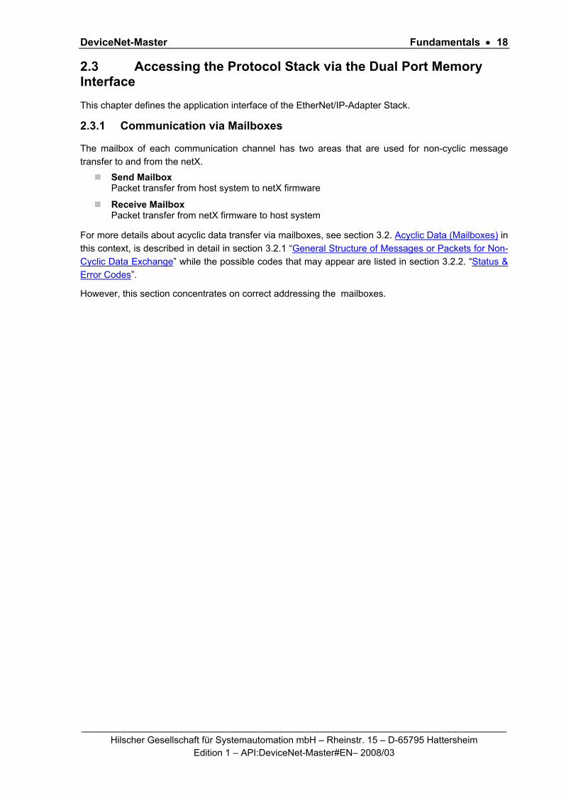
2.3.1 Communication via Mailboxes
The mailbox of each communication channel has two areas that are used for non-cyclic message transfer to and from the netX.
Send Mailbox Packet transfer from host system to netX firmware
Receive Mailbox Packet transfer from netX firmware to host system
For more details about acyclic data transfer via mailboxes, see section 3.2. Acyclic Data (Mailboxes) in this context, is described in detail in section 3.2.1 “General Structure of Messages or Packets for Non-Cyclic Data Exchange” while the possible codes that may appear are listed in section 3.2.2. “Status & Error Codes”.
However, this section concentrates on correct addressing the mailboxes.
DeviceNet-Master Fundamentals • 19
_________________________________________________________________________________ Hilscher Gesellschaft für Systemautomation mbH – Rheinstr. 15 – D-65795 Hattersheim
Edition 1 – API:DeviceNet-Master#EN– 2008/03
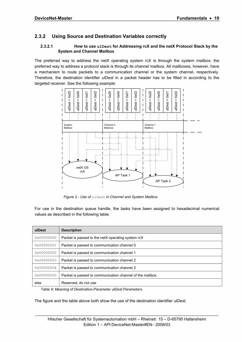
2.3.2 Using Source and Destination Variables correctly
2.3.2.1 How to use ulDest for Addressing rcX and the netX Protocol Stack by the System and Channel Mailbox
The preferred way to address the netX operating system rcX is through the system mailbox; the preferred way to address a protocol stack is through its channel mailbox. All mailboxes, however, have a mechanism to route packets to a communication channel or the system channel, respectively. Therefore, the destination identifier ulDest in a packet header has to be filled in according to the targeted receiver. See the following example:
netX OSrcX
AP Task 1
AP Task 2
ulD
est =
0x0
0
ulD
est =
0x0
1
ulD
est =
0x0
2
ulD
est =
0x2
0
ulD
est =
0x0
0
ulD
est =
0x0
1
ulD
est =
0x0
2
ulD
est =
0x2
0
ulD
est =
0x0
0
ulD
est =
0x0
1
ulD
est =
0x0
2
ulD
est =
0x2
0
SystemMailbox
Channel 1Mailbox
Channel 0Mainbox
Figure 2 - Use of ulDest in Channel and System Mailbox
For use in the destination queue handle, the tasks have been assigned to hexadecimal numerical values as described in the following table:
ulDest Description
0x00000000 Packet is passed to the netX operating system rcX
0x00000001 Packet is passed to communication channel 0
0x00000002 Packet is passed to communication channel 1
0x00000003 Packet is passed to communication channel 2
0x00000004 Packet is passed to communication channel 3
0x00000020 Packet is passed to communication channel of the mailbox
else Reserved, do not use
Table 9: Meaning of Destination-Parameter ulDest.Parameters.
The figure and the table above both show the use of the destination identifier ulDest.

DeviceNet-Master Fundamentals • 20
_________________________________________________________________________________ Hilscher Gesellschaft für Systemautomation mbH – Rheinstr. 15 – D-65795 Hattersheim
Edition 1 – API:DeviceNet-Master#EN– 2008/03
A remark on the special channel identifier 0x00000020 (= Channel Token). The Channel Token is valid for any mailbox. That way the application uses the same identifier for all packets without actually knowing which mailbox or communication channel is applied. The packet stays 'local'. The system mailbox is a little bit different, because it is used to communicate to the netX operating system rcX. The rcX has its own range of valid commands codes and differs from a communication channel.
Unless there is a reply packet, the netX operating system returns it to the same mailbox the request packet went through. Consequently, the host application has to return its reply packet to the mailbox the request was received from.
2.3.2.2 How to use ulSrc and ulSrcId
Generally, a netX protocol stack can be addressed through its communication channel mailbox. The example below shows how a host application addresses a protocol stack running in the context of a netX chip. The application is identified by a number (#444 in this example). The application consists of three processes identified by the numbers #11, #22 and #33. These processes communicate through the channel mailbox with the AP task of the protocol stack. Have a look at the following figure:
Application #444
netX Protocol stackAP Task 1
Pro
cess
#22
Pro
cess
#33
Pro
cess
#11
ChannelMainbox
Figure 3 - Using ulSrc and ulSrcId

DeviceNet-Master Fundamentals • 21
_________________________________________________________________________________ Hilscher Gesellschaft für Systemautomation mbH – Rheinstr. 15 – D-65795 Hattersheim
Edition 1 – API:DeviceNet-Master#EN– 2008/03
Example:
This example applies to command messages initiated by a process in the context of the host application. If the process #22 sends a packet through the channel mailbox to the AP task, the packet header has to be filled in as follows:
Object Variable Name
Numeric Value Explanation
Destination Queue Handle
ulDest = 32
(0x00000020)
This value needs always to be set to 0x00000020 (the channel token) when accessing the protocol stack via the local communication channel mailbox.
Source Queue Handle
ulSrc = 444 Denotes the host application (#444).
Destination Identifier
ulDestId = 0 In this example, it is not necessary to use the destination identifier.
Source Identifier
ulSrcId = 22 Denotes the process number of the process within the host application and needs therefore to be supplied by the programmer of the host application.
Table 10: Example for correct Use of Source- and Destination-related Parameters.:
For packets through the channel mailbox, the application uses 32 (= 0x20, Channel Token) for the destination queue handler ulDest. The source queue handler ulSrc and the source identifier ulSrcId are used to identify the originator of a packet. The destination identifier ulDestId can be used to address certain resources in the protocol stack. It is not used in this example. The source queue handler ulSrc has to be filled in. Therefore, its use is mandatory; the use of ulSrcId is optional.
The netX operating system passes the request packet to the protocol stack's AP task. The protocol stack then builds a reply to the packet and returns it to the mailbox. The application has to make sure that the packet finds its way back to the originator (process #22 in the example).
2.3.2.3 How to Route rcX Packets
To route an rcX packet the source identifier ulSrcId and the source queues handler ulSrc in the packet header hold the identification of the originating process. The router saves the original handle from ulSrcId and ulSrc. The router uses a handle of its own choices for ulSrcId and ulSrc before it sends the packet to the receiving process. That way the router can identify the corresponding reply packet and matches the handle from that packet with the one stored earlier. Now the router replaces its handles with the original handles and returns the packet to the originating process.
DeviceNet-Master Fundamentals • 22
_________________________________________________________________________________ Hilscher Gesellschaft für Systemautomation mbH – Rheinstr. 15 – D-65795 Hattersheim
Edition 1 – API:DeviceNet-Master#EN– 2008/03
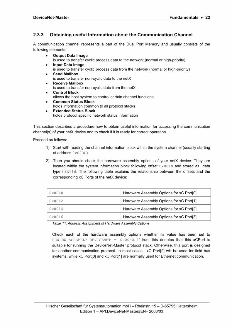
2.3.3 Obtaining useful Information about the Communication Channel
A communication channel represents a part of the Dual Port Memory and usually consists of the following elements:
• Output Data Image is used to transfer cyclic process data to the network (normal or high-priority)
• Input Data Image is used to transfer cyclic process data from the network (normal or high-priority)
• Send Mailbox is used to transfer non-cyclic data to the netX
• Receive Mailbox is used to transfer non-cyclic data from the netX
• Control Block allows the host system to control certain channel functions
• Common Status Block holds information common to all protocol stacks
• Extended Status Block holds protocol specific network status information
This section describes a procedure how to obtain useful information for accessing the communication channel(s) of your netX device and to check if it is ready for correct operation.
Proceed as follows:
1) Start with reading the channel information block within the system channel (usually starting at address 0x0030).
2) Then you should check the hardware assembly options of your netX device. They are located within the system information block following offset 0x0010 and stored as data type UINT16. The following table explains the relationship between the offsets and the corresponding xC Ports of the netX device:
0x0010 Hardware Assembly Options for xC Port[0]
0x0012 Hardware Assembly Options for xC Port[1]
0x0014 Hardware Assembly Options for xC Port[2]
0x0016 Hardware Assembly Options for xC Port[3] Table 11: Address Assignment of Hardware Assembly Options
Check each of the hardware assembly options whether its value has been set to RCX_HW_ASSEMBLY_DEVICENET = 0x0040. If true, this denotes that this xCPort is suitable for running the DeviceNet-Master protocol stack. Otherwise, this port is designed for another communication protocol. In most cases, xC Port[2] will be used for field bus systems, while xC Port[0] and xC Port[1] are normally used for Ethernet communication.
DeviceNet-Master Fundamentals • 23
_________________________________________________________________________________ Hilscher Gesellschaft für Systemautomation mbH – Rheinstr. 15 – D-65795 Hattersheim
Edition 1 – API:DeviceNet-Master#EN– 2008/03
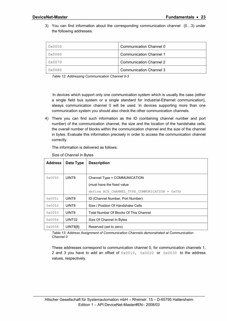
3) You can find information about the corresponding communication channel (0…3) under the following addresses:
0x0050 Communication Channel 0
0x0060 Communication Channel 1
0x0070 Communication Channel 2
0x0080 Communication Channel 3 Table 12: Addressing Communication Channel 0-3
In devices which support only one communication system which is usually the case (either a single field bus system or a single standard for Industrial-Ethernet communication), always communication channel 0 will be used. In devices supporting more than one communication system you should also check the other communication channels.
4) There you can find such information as the ID (containing channel number and port number) of the communication channel, the size and the location of the handshake cells, the overall number of blocks within the communication channel and the size of the channel in bytes. Evaluate this information precisely in order to access the communication channel correctly.
The information is delivered as follows:
Size of Channel in Bytes
Address Data Type
Description
0x0050 UINT8 Channel Type = COMMUNICATION
(must have the fixed value
define RCX_CHANNEL_TYPE_COMMUNICATION = 0x05)
0x0051 UINT8 ID (Channel Number, Port Number)
0x0052 UINT8 Size / Position Of Handshake Cells
0x0053 UINT8 Total Number Of Blocks Of This Channel
0x0054 UINT32 Size Of Channel In Bytes
0x0058 UINT8[8] Reserved (set to zero)
Table 13: Address Assignment of Communication Channels demonstrated at Communication Channel 0
These addresses correspond to communication channel 0, for communication channels 1, 2 and 3 you have to add an offset of 0x0010, 0x0020 or 0x0030 to the address values, respectively.

DeviceNet-Master Fundamentals • 24
_________________________________________________________________________________ Hilscher Gesellschaft für Systemautomation mbH – Rheinstr. 15 – D-65795 Hattersheim
Edition 1 – API:DeviceNet-Master#EN– 2008/03
2.4 Client/Server Mechanism
2.4.1 Application as Client
The host application may send request packets to the netX firmware at any time (transition 1 2). Depending on the protocol stack running on the netX, parallel packets are not permitted (see protocol specific manual for details). The netX firmware sends a confirmation packet in return, signaling success or failure (transition 3 4) while processing the request.
The host application has to register with the netX firmware in order to receive indication packets (transition 5 6). Depending on the protocol stack, this is done either implicit (if application opens a TCP/UDP socket) or explicit (if application wants to receive unsolicited DPV1 packets). Details on when and how to register for certain events is described in the protocol specific manual. Depending on the command code of the indication packet, a response packet to the netX firmware may or may not be required (transition 7 8).
Figure 4: Transition Chart Application as Client
The host application sends request packets to the netX firmware.
The netX firmware sends a confirmation packet in return.
The host application receives indication packets from the netX firmware.
The host application sends response packet to the netX firmware (may not be required).
Request Confirmation
Indication Response
Application netX

DeviceNet-Master Fundamentals • 25
_________________________________________________________________________________ Hilscher Gesellschaft für Systemautomation mbH – Rheinstr. 15 – D-65795 Hattersheim
Edition 1 – API:DeviceNet-Master#EN– 2008/03
2.4.2 Application as Server
The host application has to register with the netX firmware in order to receive indication packets. Depending on the protocol stack, this is done either implicit (if application opens a TCP/UDP socket) or explicit (if application wants to receive unsolicited DPV1 packets). Details on when and how to register for certain events is described in the protocol specific manual.
When an appropriate event occurs and the host application is registered to receive such a notification, the netX firmware passes an indication packet through the mailbox (transition 1 2). The host application is expected to send a response packet back to the netX firmware (transition 3 4).
Figure 5: Transition Chart Application as Server
The netX firmware passes an indication packet through the mailbox.
The host application sends response packet to the netX firmware. Indication Response
Application netX

DeviceNet-Master Dual-Port Memory • 26
_________________________________________________________________________________ Hilscher Gesellschaft für Systemautomation mbH – Rheinstr. 15 – D-65795 Hattersheim
Edition 1 – API:DeviceNet-Master#EN– 2008/03
3 Dual-Port Memory All data in the dual-port memory is structured in blocks. According to their functions, these blocks use different data transfer mechanisms. For example, data transfer through mailboxes uses a synchronized handshake mechanism between host system and netX firmware. The same is true for IO data images, when a buffered handshake mode is configured. Other blocks, like the status block, are read by the host application and use no synchronization mechanism.
Types of blocks in the dual-port memory are outlined below:
• Mailbox transfer non-cyclic messages or packages with a header for routing information
• Data Area holds the process image for cyclic I/O data or user defined data structures
• Control Block is used to signal application related state to the netX firmware
• Status Block holds information regarding the current network state
• Change of State collection of flags that initiate execution of certain commands or signal a change of state
3.1 Cyclic Data (Input/Output Data) The input block holds the process data image received from the network whereas the output block holds data sent to the network
For the controlled / buffered mode, the protocol stack updates the process data in the internal input buffer for each valid bus cycle. Each IO block uses handshake bits for access synchronization. Input and output data block handshake operates independently from each other. When the application toggles the input handshake bit, the protocol stack copies the data from the internal buffer into the input data image of the dual-port memory. Now the application can copy data from the dual-port memory and then give control back to the protocol stack by toggling the appropriate input handshake bit. When the application/driver toggles the output handshake bit, the protocol stack copies the data from the output data image of the dual-port memory into the internal buffer. From there the data is transferred to the network. The protocol stack toggles the handshake bits back, indicating to the application that the transfer is finished and a new data exchange cycle may start. This mode guarantees data consistency over both input and output area.

DeviceNet-Master Dual-Port Memory • 27
_________________________________________________________________________________ Hilscher Gesellschaft für Systemautomation mbH – Rheinstr. 15 – D-65795 Hattersheim
Edition 1 – API:DeviceNet-Master#EN– 2008/03
3.1.1 Input Process Data
The input data block is used by field bus and industrial Ethernet protocols that utilize a cyclic data exchange mechanism. The input data image is used to receive cyclic data from the network.
The default size of the input data image is 5760 byte. However, not all available space is actually used by the protocol stack. Depending on the specific protocol, the area actually available for user data might be much smaller than 5760 byte. An input data block may or may not be available in the dual-port memory. It is always available in the default memory map (see the netX Dual-Port Memory Manual).
Input Data Image
Offset Type Name Description
0x2680
UINT8 abPd0Input[5760] Input Data Image
Cyclic Data From The Network
Table 14: Input Data Image
3.1.2 Output Process Data
The output data block is used by field bus and industrial Ethernet protocols that utilize a cyclic data exchange mechanism. The output data Image is used to send cyclic data from the host to the network.
The default size of the output data image is 5760 byte. However, not all available space is actually used by the protocol stack. Depending on the specific protocol, the area actually available for user data might be much smaller than 5760 byte. An output data block may or may not be available in the dual-port memory. It is always available in the default memory map (see netX DPM Manual).
Output Data Image
Offset Type Name Description
0x1000 UINT8 abPd0Output[5760] Output Data Image
Cyclic Data To The Network
Table 15: Output Data Image
DeviceNet-Master Dual-Port Memory • 28
_________________________________________________________________________________ Hilscher Gesellschaft für Systemautomation mbH – Rheinstr. 15 – D-65795 Hattersheim
Edition 1 – API:DeviceNet-Master#EN– 2008/03
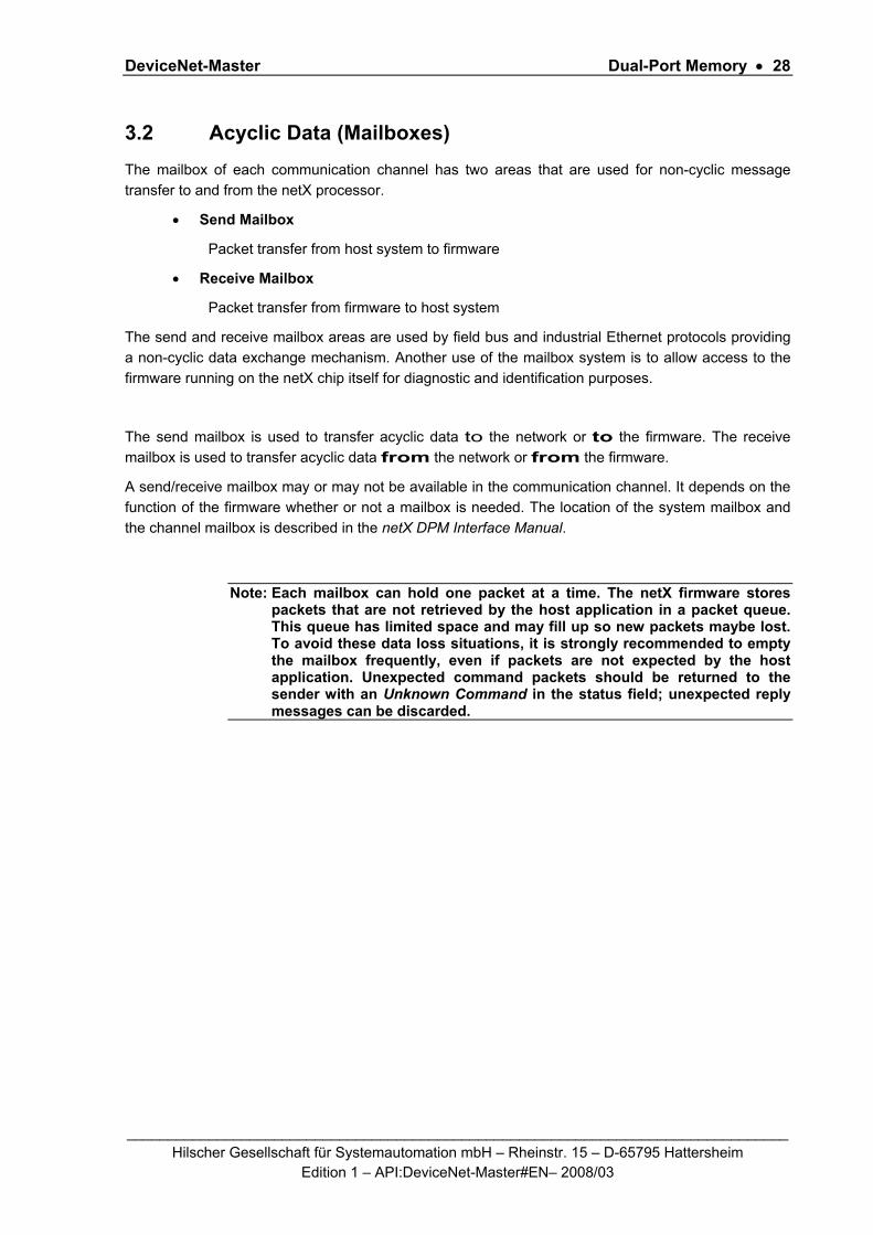
3.2 Acyclic Data (Mailboxes) The mailbox of each communication channel has two areas that are used for non-cyclic message transfer to and from the netX processor.
• Send Mailbox
Packet transfer from host system to firmware
• Receive Mailbox
Packet transfer from firmware to host system
The send and receive mailbox areas are used by field bus and industrial Ethernet protocols providing a non-cyclic data exchange mechanism. Another use of the mailbox system is to allow access to the firmware running on the netX chip itself for diagnostic and identification purposes.
The send mailbox is used to transfer acyclic data to the network or to the firmware. The receive mailbox is used to transfer acyclic data from the network or from the firmware.
A send/receive mailbox may or may not be available in the communication channel. It depends on the function of the firmware whether or not a mailbox is needed. The location of the system mailbox and the channel mailbox is described in the netX DPM Interface Manual.
Note: Each mailbox can hold one packet at a time. The netX firmware stores packets that are not retrieved by the host application in a packet queue. This queue has limited space and may fill up so new packets maybe lost. To avoid these data loss situations, it is strongly recommended to empty the mailbox frequently, even if packets are not expected by the host application. Unexpected command packets should be returned to the sender with an Unknown Command in the status field; unexpected reply messages can be discarded.

DeviceNet-Master Dual-Port Memory • 29
_________________________________________________________________________________ Hilscher Gesellschaft für Systemautomation mbH – Rheinstr. 15 – D-65795 Hattersheim
Edition 1 – API:DeviceNet-Master#EN– 2008/03
3.2.1 General Structure of Messages or Packets for Non-Cyclic Data Exchange
The non-cyclic packets through the netX mailbox have the following structure:
Structure Information
Area Variable Type Value / Range Description
Head Structure Information
ulDest UINT32 Destination Queue Handle
ulSrc UINT32 Source Queue Handle
ulDestId UINT32 Destination Queue Reference
ulSrcId UINT32 Source Queue Reference
ulLen UINT32 Packet Data Length (In Bytes)
ulId UINT32 Packet Identification As Unique Number
ulSta UINT32 Status / Error Code
ulCmd UINT32 Command / Response
ulExt UINT32 Extension Flags
ulRout UINT32 Routing Information
Data Structure Information
… … User Data Specific To The Command
Table 16: General Structure of Packets for non-cyclic Data Exchange.
Some of the fields are mandatory; some are conditional; others are optional. However, the size of a
packet is always at least 10 double-words or 40 bytes. Depending on the command, a packet may or
may not have a data field. If present, the content of the data field is specific to the command,
respectively the reply.
Destination Queue Handle
The ulDest field identifies a task queue in the context of the netX firmware. The task queue represents
the final receiver of the packet and is assigned to a protocol stack. The ulDest field has to be filled out
in any case. Otherwise, the netX operating system cannot route the packet. This field is mandatory.
Source Queue Handle

DeviceNet-Master Dual-Port Memory • 30
_________________________________________________________________________________ Hilscher Gesellschaft für Systemautomation mbH – Rheinstr. 15 – D-65795 Hattersheim
Edition 1 – API:DeviceNet-Master#EN– 2008/03
The ulSrc field identifies the sender of the packet. In the context of the netX firmware (inter-task
communication) this field holds the identifier of the sending task. Usually, a driver uses this field for its
own handle, but it can hold any handle of the sending process. Using this field is mandatory. The
receiving task does not evaluate this field and passes it back unchanged to the originator of the
packet.
Destination Identifier
The ulDestId field identifies the destination of an unsolicited packet from the netX firmware to the host
system. It can hold any handle that helps to identify the receiver. Therefore, its use is mandatory for
unsolicited packets. The receiver of unsolicited packets has to register for this.
Source Identifier
The ulSrcId field identifies the originator of a packet. This field is used by a host application, which
passes a packet from an external process to an internal netX task. The ulSrcId field holds the handle
of the external process. When netX operating system returns the packet, the application can identify
the packet and returns it to the originating process. The receiving task on the netX does not evaluate
this field and passes it back unchanged. For inter-task communication, this field is not used.
Length of Data Field
The ulLen field holds the size of the data field in bytes. It defines the total size of the packet’s payload
that follows the packet’s header. The size of the header is not included in ulLen. So the total size of a
packet is the size from ulLen plus the size of packet’s header. Depending on the command, a data
field may or may not be present in a packet. If no data field is included, the length field is set to zero.
Identifier
The ulId field is used to identify a specific packet among others of the same kind. That way the
application or driver can match a specific reply or confirmation packet to a previous request packet.
The receiving task does not change this field and passes it back to the originator of the packet. Its use
is optional in most of the cases. However, it is mandatory for sequenced packets.
Example: Downloading big amounts of data that does not fit into a single packet. For a sequence of packets the identifier field is incremented by one for every new packet.
Status / Error Code
DeviceNet-Master Dual-Port Memory • 31
_________________________________________________________________________________ Hilscher Gesellschaft für Systemautomation mbH – Rheinstr. 15 – D-65795 Hattersheim
Edition 1 – API:DeviceNet-Master#EN– 2008/03
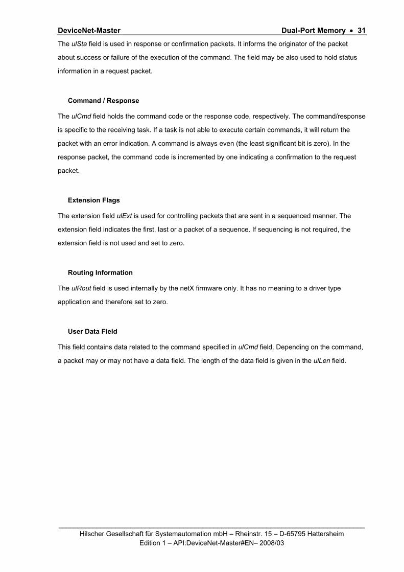
The ulSta field is used in response or confirmation packets. It informs the originator of the packet
about success or failure of the execution of the command. The field may be also used to hold status
information in a request packet.
Command / Response
The ulCmd field holds the command code or the response code, respectively. The command/response
is specific to the receiving task. If a task is not able to execute certain commands, it will return the
packet with an error indication. A command is always even (the least significant bit is zero). In the
response packet, the command code is incremented by one indicating a confirmation to the request
packet.
Extension Flags
The extension field ulExt is used for controlling packets that are sent in a sequenced manner. The
extension field indicates the first, last or a packet of a sequence. If sequencing is not required, the
extension field is not used and set to zero.
Routing Information
The ulRout field is used internally by the netX firmware only. It has no meaning to a driver type
application and therefore set to zero.
User Data Field
This field contains data related to the command specified in ulCmd field. Depending on the command,
a packet may or may not have a data field. The length of the data field is given in the ulLen field.

DeviceNet-Master Dual-Port Memory • 32
_________________________________________________________________________________ Hilscher Gesellschaft für Systemautomation mbH – Rheinstr. 15 – D-65795 Hattersheim
Edition 1 – API:DeviceNet-Master#EN– 2008/03
3.2.2 Status & Error Codes The following status and error codes can be returned in ulSta:
Status and Error Codes
Code (Symbolic Constant) Numerical Value Meaning
RCX_S_OK 0x00000000 SUCCESS, STATUS OKAY
RCX_S_QUE_UNKNOWN 0xC02B0001 UNKNOWN QUEUE
RCX_S_QUE_INDEX_UNKNOWN 0xC02B0002 UNKNOWN QUEUE INDEX
RCX_S_TASK_UNKNOWN 0xC02B0003 UNKNOWN TASK
RCX_S_TASK_INDEX_UNKNOWN 0xC02B0004 UNKNOWN TASK INDEX
RCX_S_TASK_HANDLE_INVALID 0xC02B0005 INVALID TASK HANDLE
RCX_S_TASK_INFO_IDX_UNKNOWN 0xC02B0006 UNKNOWN INDEX
RCX_S_FILE_XFR_TYPE_INVALID 0xC02B0007 INVALID TRANSFER TYPE
RCX_S_FILE_REQUEST_INCORRECT 0xC02B0008 INVALID FILE REQUEST
RCX_S_UNKNOWN_DESTINATION 0xC0000005 UNKNOWN DESTINATION
RCX_S_UNKNOWN_DESTINATION_ID 0xC0000006 UNKNOWN DESTINATION ID
RCX_S_INVALID_LENGTH 0xC0000007 INVALID LENGTH
RCX_S_UNKNOWN_COMMAND 0xC0000004 UNKNOWN COMMAND
RCX_S_INVALID_EXTENSION 0xC0000008 INVALID EXTENSION
Table 17: Status and Error Codes.
3.2.3 Differences between System and Channel Mailboxes
The mailbox system on netX provides a non-cyclic data transfer channel for field bus and industrial Ethernet protocols. Another use of the mailbox is allowing access to the firmware running on the netX chip itself for diagnostic purposes. There is always a send and a receive mailbox. Send and receive mailboxes utilize handshake bits to synchronize these data or diagnostic packages through the mailbox. There is a pair of handshake bits for both the send and receive mailbox.
The netX operating system rcX only uses the system mailbox. • The system mailbox, however, has a mechanism to route packets to a communication
channel. • A channel mailbox passes packets to its own protocol stack only.
DeviceNet-Master Dual-Port Memory • 33
_________________________________________________________________________________ Hilscher Gesellschaft für Systemautomation mbH – Rheinstr. 15 – D-65795 Hattersheim
Edition 1 – API:DeviceNet-Master#EN– 2008/03
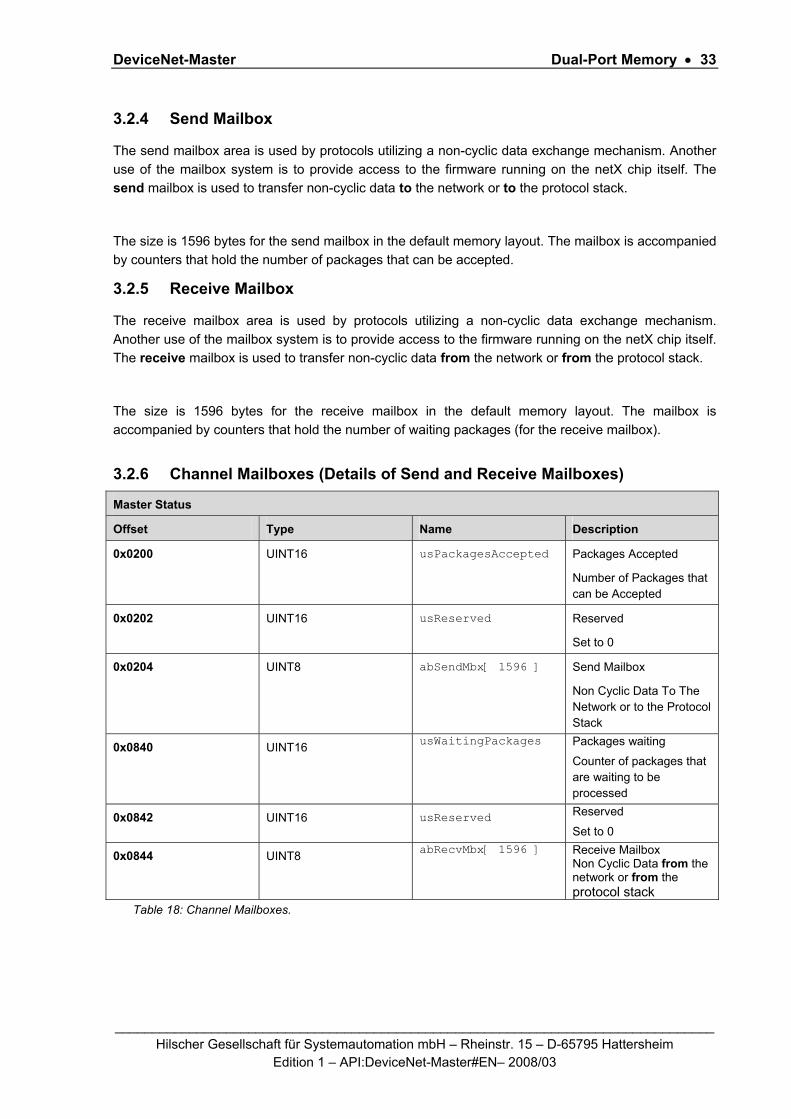
3.2.4 Send Mailbox
The send mailbox area is used by protocols utilizing a non-cyclic data exchange mechanism. Another use of the mailbox system is to provide access to the firmware running on the netX chip itself. The send mailbox is used to transfer non-cyclic data to the network or to the protocol stack.
The size is 1596 bytes for the send mailbox in the default memory layout. The mailbox is accompanied by counters that hold the number of packages that can be accepted.
3.2.5 Receive Mailbox
The receive mailbox area is used by protocols utilizing a non-cyclic data exchange mechanism. Another use of the mailbox system is to provide access to the firmware running on the netX chip itself. The receive mailbox is used to transfer non-cyclic data from the network or from the protocol stack.
The size is 1596 bytes for the receive mailbox in the default memory layout. The mailbox is accompanied by counters that hold the number of waiting packages (for the receive mailbox).
3.2.6 Channel Mailboxes (Details of Send and Receive Mailboxes)
Master Status
Offset Type Name Description
0x0200 UINT16 usPackagesAccepted Packages Accepted
Number of Packages that can be Accepted
0x0202 UINT16 usReserved Reserved
Set to 0
0x0204
UINT8 abSendMbx[ 1596 ] Send Mailbox
Non Cyclic Data To The Network or to the Protocol Stack
0x0840 UINT16 usWaitingPackages
Packages waiting
Counter of packages that are waiting to be processed
0x0842 UINT16 usReserved Reserved
Set to 0
0x0844 UINT8 abRecvMbx[ 1596 ]
Receive Mailbox Non Cyclic Data from the network or from the protocol stack
Table 18: Channel Mailboxes.

DeviceNet-Master Dual-Port Memory • 34
_________________________________________________________________________________ Hilscher Gesellschaft für Systemautomation mbH – Rheinstr. 15 – D-65795 Hattersheim
Edition 1 – API:DeviceNet-Master#EN– 2008/03
Channel Mailboxes Structure typedef struct tagNETX_SEND_MAILBOX_BLOCK { UINT16 usPackagesAccepted; UINT16 usReserved; UINT8 abSendMbx[ 1596 ]; } NETX_SEND_MAILBOX_BLOCK; typedef struct tagNETX_RECV_MAILBOX_BLOCK { UINT16 usWaitingPackages; UINT16 usReserved; UINT8 abRecvMbx[ 1596 ]; } NETX_RECV_MAILBOX_BLOCK;
3.3 Status A status block is present in both system and communication channel. It contains information about network and task related issues. In some respects, status and control block are used together in order to exchange information between host application and netX firmware. The application reads a status block whereas the control block is written by the application. Both status and control block have registers that use the Change of State mechanism (see also section 2.2.1 of the netX Dual-Port-Memory manual).
3.3.1 Common Status
The Common Status Block contains information that is the same for all communication channels. The start offset of this block depends on the size and location of the preceding blocks. The status block is always present in the dual-port memory.

DeviceNet-Master Dual-Port Memory • 35
_________________________________________________________________________________ Hilscher Gesellschaft für Systemautomation mbH – Rheinstr. 15 – D-65795 Hattersheim
Edition 1 – API:DeviceNet-Master#EN– 2008/03
3.3.1.1 All Implementations
The structure outlined below is common to all protocol stacks:
Common Status Block
Offset Type Name Description
0x0010 UINT32 ulCommunicationCOS Communication Change of State READY, RUN, RESET REQUIRED, NEW CONFIG AVAILABLE, CONFIG LOCKED
0x0014 UINT32 ulCommunicationState Communication State NOT CONFIGURED, STOP, IDLE, OPERATE
0x0018 UINT32 ulCommunicationError Communication Error Unique Error Number According to Protocol Stack(not supported yet)
0x001C UINT16 usVersion Version Version Number of this Diagnosis Structure
0x001E UINT16 usWatchdogTime Watchdog Timeout Configured Watchdog Time
0x0020 UINT16[ ] ausProtocolClass[2] Protocol Class MASTER, SLAVE, CLIENT, SERVER, GATEWAY…
0x0024 UINT32 ulHostWatchdog Host Watchdog Joint Supervision Mechanism Protocol Stack Writes, Host System Reads
0x0028 UINT32 ulErrorCount Error Count Total Number of Detected Error Since Power-Up or Reset
0x002C UINT32 ulErrorLogInd Error Log Indicator Total Number Of Entries In The Error Log Structure (not supported yet)
0x0030 UINT32[ ] aulReserved[2] Reserved Set to 0
Table 19: Common Status Block

DeviceNet-Master Dual-Port Memory • 36
_________________________________________________________________________________ Hilscher Gesellschaft für Systemautomation mbH – Rheinstr. 15 – D-65795 Hattersheim
Edition 1 – API:DeviceNet-Master#EN– 2008/03
Common Status Block Structure
typedef struct tagNETX_COMMON_STATUS_BLOCK { UINT32 ulCommunicationCOS; UINT32 ulCommunicationState; UINT32 ulCommunicationError; UINT16 usVersion; UINT16 usWatchdogTime; UINT16 ausProtocolClass[2]; UINT32 ulHostWatchdog; UINT32 ulErrorCount; UINT32 ulErrorLogInd; UINT32 aulReserved[2]; union { NETX_MASTER_STATUS tMasterStatus; /* for master implementation */ UINT32 aulReserved[6]; /* otherwise reserved */ } uStackDepended; } NETX_COMMON_STATUS_BLOCK;
Communication Change of State (All Implementations)
The communication change of state register contains information about the current operating status of the communication channel and its firmware. Every time the status changes, the netX protocol stack toggles the netX Change of State Command flag in the netX communication flags register (see section 3.2.2.1 of the netX DPM Interface Manual). The application then has to toggle the netX Change of State Acknowledge flag back acknowledging the new state (see section 3.2.2.2 of the netX DPM Interface Manual).
Operating State READY #define RCX_COMM_COS_READY 0x00000001
The Ready flag is set as soon as the protocol stack is started properly. Then the protocol stack is awaiting a configuration.
RUNNING #define RCX_COMM_COS_RUN 0x00000002 The Running flag is set when the protocol stack has been configured properly. Then the protocol stack is awaiting a network connection.
RESTART REQUIRED #define RCX_COMM_COS_RESTART_REQUIRED 0x00000004 The Restart Required flag is set when the channel firmware requests to be reset. This may be caused if a new configuration was downloaded form the host application or if a configuration upload via the network took place.
CONFIGURATION AVAILABLE #define RCX_COMM_COS_CONFIG_AVAIL 0x00000008 The Configuration Available flag is set when a new configuration file is available for the channel firmware which has not been yet set active. This flag may be set together with the Restart Required flag.
CONFIGURATION LOCKED #define RCX_COMM_COS_CONFIG_LOCKED 0x00000010 The Configuration Locked flag is set, if the communication channel firmware has locked the current configuration database against being overwritten. Additionally, re-initializing the channel is not allowed in this state. To unlock the database, the application has to clear the Lock Configuration flag in the control block (see section 3.2.4 of the netX DPM Interface Manual).
Others are reserved.

DeviceNet-Master Dual-Port Memory • 37
_________________________________________________________________________________ Hilscher Gesellschaft für Systemautomation mbH – Rheinstr. 15 – D-65795 Hattersheim
Edition 1 – API:DeviceNet-Master#EN– 2008/03
Communication State (All Implementations)
The communication state field contains information regarding the current network status of the communication channel. Depending on the implementation, all or a subset of the definitions below is supported.
UNKNOWN #define RCX_COMM_STATE_UNKNOWN 0x00000000
NOT CONFIGURED #define RCX_COMM_STATE_NOT_CONFIGURED 0x00000001
STOP #define RCX_COMM_STATE_STOP 0x00000002
IDLE #define RCX_COMM_STATE_IDLE 0x00000003
OPERATE #define RCX_COMM_STATE_OPERATE 0x00000004
Communication Channel Error (All Implementations)
This field holds the current error code of the communication channel. If the error is resolved, the communication error field is set to zero (= RCX_COMM_SUCCESS) again. Not all of the error codes are supported in every implementation. Protocol stacks may use a subset of the error codes below.
SUCCESS #define RCX_COMM_SUCCESS 0x00000000
Runtime Failures WATCHDOG TIMEOUT #define RCX_COMM_WATCHDOG_TIMEOUT 0xC000000C
Initialization Failures (General) INITIALIZATION FAULT
#define RCX_COMM_INIT_FAULT 0xC0000100
DATABASE ACCESS FAILED #define RCX_COMM_DATABASE_ACCESS_FAILED 0xC0000101
Configuration Failures (General) CONFIGURATION FAULT
#define RCX_COMM_CONFIGURATION_FAULT 0xC0000120
INCONSISTENT DATA SET #define RCX_COMM_INCONSISTENT_DATA_SET 0xC0000121
DATA SET MISMATCH #define RCX_COMM_DATA_SET_MISMATCH 0xC0000122
INSUFFICIENT LICENSE #define RCX_COMM_INSUFFICIENT_LICENSE 0xC0000123
PARAMETER ERROR #define RCX_COMM_PARAMETER_ERROR 0xC0000124
INVALID NETWORK ADDRESS #define RCX_COMM_INVALID_NETWORK_ADDRESS 0xC0000125
Network Failures (General) NETWORK FAULT #define RCX_COMM_NETWORK_FAULT 0xC0000140
CONNECTION CLOSED #define RCX_COMM_CONNECTION_CLOSED 0xC0000141
CONNECTION TIMED OUT #define RCX_COMM_CONNECTION_TIMEOUT 0xC0000142
LONELY NETWORK #define RCX_COMM_LONELY_NETWORK 0xC0000143
DUPLICATE NODE #define RCX_COMM_DUPLICATE_NODE 0xC0000144
CABLE DISCONNECT #define RCX_COMM_CABLE_DISCONNECT 0xC0000145

DeviceNet-Master Dual-Port Memory • 38
_________________________________________________________________________________ Hilscher Gesellschaft für Systemautomation mbH – Rheinstr. 15 – D-65795 Hattersheim
Edition 1 – API:DeviceNet-Master#EN– 2008/03
Version (All Implementations)
The version field holds version of this structure. It starts with one; zero is not defined.
STRUCTURE VERSION #define RCX_STATUS_BLOCK_VERSION 0x0001
Watchdog Timeout (All Implementations)
This field holds the configured watchdog timeout value in milliseconds. The application may set its watchdog trigger interval accordingly. If the application fails to copy the value from the host watchdog location to the device watchdog location, the protocol stack will interrupt all network connections immediately regardless of their current state. For details, see section 4.13 of the netX DPM Interface Manual.
Protocol Class (All Implementations)
This field identifies the protocol class of the communication channel. The field is split into a communication class field and communication sub class field. The first array element represents the communication class; the second element is the communication sub class.
Communication Class
This array element holds further information regarding the protocol stack. It is intended to help identifying the 'communication class' or 'device class' of the protocol.
UNDEFINED #define RCX_COMM_CLASS_UNDEFINED 0x0000
UNCLASSIFIABLE #define RCX_COMM_CLASS_UNCLASSIFIABLE 0x0001
MASTER #define RCX_COMM_CLASS_MASTER 0x0002
SLAVE #define RCX_COMM_CLASS_SLAVE 0x0003
SCANNER #define RCX_COMM_CLASS_SCANNER 0x0004
ADAPTER #define RCX_COMM_CLASS_ADAPTER 0x0005
MESSAGING #define RCX_COMM_CLASS_MESSAGING 0x0006
CLIENT #define RCX_COMM_CLASS_CLIENT 0x0007
SERVER #define RCX_COMM_CLASS_SERVER 0x0008
IO-CONTROLLER #define RCX_COMM_CLASS_IO_CONTROLLER 0x0009
IO-DEVICE #define RCX_COMM_CLASS_IO_DEVICE 0x000A
IO-SUPERVISOR #define RCX_COMM_CLASS_IO_SUPERVISOR 0x000B
GATEWAY #define RCX_COMM_CLASS_GATEWAY 0x000C
MONITOR #define RCX_COMM_CLASS_MONITOR 0x000D
PRODUCER #define RCX_COMM_CLASS_PRODUCER 0x000E
CONSUMER #define RCX_COMM_CLASS_CONSUMER 0x000F
SWITCH #define RCX_COMM_CLASS_SWITCH 0x0010
HUB #define RCX_COMM_CLASS_HUB 0x0011
Others are reserved.

DeviceNet-Master Dual-Port Memory • 39
_________________________________________________________________________________ Hilscher Gesellschaft für Systemautomation mbH – Rheinstr. 15 – D-65795 Hattersheim
Edition 1 – API:DeviceNet-Master#EN– 2008/03
Communication Sub Class
The communication sub class of a device is determined by the implementation and therefore described in a separate manual.
UNDEFINED #define RCX_COMM_SUB_CLASS_UNDEFINED 0x0000
UNCLASSIFIABLE #define RCX_COMM_SUB_CLASS_UNCLASSIFIABLE 0x0001
NOT USED #define RCX_COMM_SUB_CLASS_NOT_USED 0x0002
Others are determined by the protocol stack and therefore defined in a separate manual.
Host Watchdog (All Implementations)
The protocol stack supervises the host system using the watchdog function. If the application fails to copy the value from the device watchdog location (section 3.2.5 of the netX DPM Interface Manual) to the host watchdog location (section 3.2.4 of the netX DPM Interface Manual), the protocol stack assumes that the host system has some sort of problem and shuts down all network connections. For details on the watchdog function, refer to section 4.13 of the netX DPM Interface Manual.
Error Count (All Implementations)
This field holds the total number of errors detected since power-up, respectively after reset. The protocol stack counts all sorts of errors in this field no matter if they were network related or caused internally.
Error Log Indicator (All Implementations)
The error log indicator field holds the number of entries in the internal error log. If all entries are read from the log, the field is set to zero. The error log indicator is not supported yet.

DeviceNet-Master Dual-Port Memory • 40
_________________________________________________________________________________ Hilscher Gesellschaft für Systemautomation mbH – Rheinstr. 15 – D-65795 Hattersheim
Edition 1 – API:DeviceNet-Master#EN– 2008/03
3.3.1.2 Master Implementation
In addition to the common status block as outlined in the previous section, a master firmware maintains the following structure.
Master Status Structure Definition
typedef struct tagNETX_MASTER_STATUS { UINT32 ulSlaveState; UINT32 ulSlaveErrLogInd; UINT32 ulNumOfConfigSlaves; UINT32 ulNumOfActiveSlaves; UINT32 ulNumOfDiagSlaves; UINT32 ulReserved; } NETX_MASTER_STATUS;
Master Status
Offset Type Name Description
0x0010 Structure See common structure in table Common Status Block
0x0038 UINT32 ulSlaveState Slave State
OK, FAILED (At Least One Slave)
0x003C UINT32 ulSlaveErrLogInd
Slave Error Log Indicator
Slave Diagnosis Data Available:
EMPTY, AVAILABLE
0x0040 UINT32 ulNumOfConfigSlaves Configured Slaves
Number of Configured Slaves On The Network
0x0044 UINT32 ulNumOfActiveSlaves Active Slaves
Number of Slaves Running Without Problems
0x0048 UINT32 ulNumOfDiagSlaves Faulted Slaves
Number of Slaves Reporting Diagnostic Issues
0x004C UINT32 ulReserved Reserved Set to 0
Table 20: Master Status Structure Definition
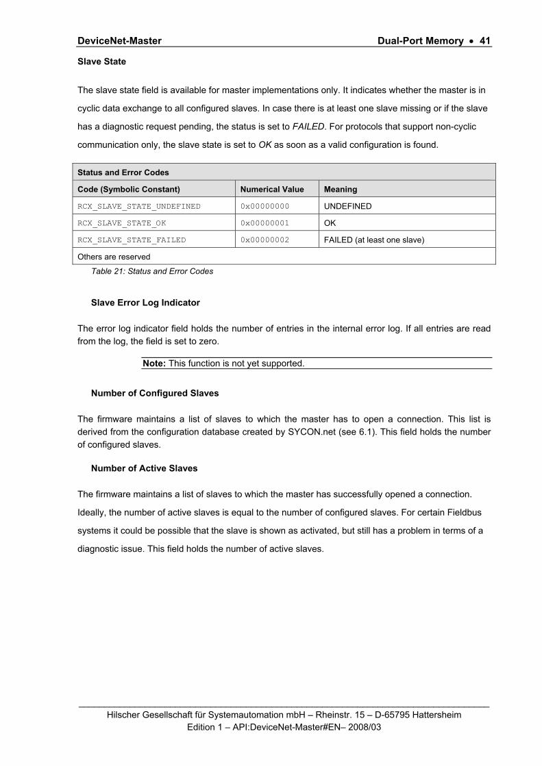
DeviceNet-Master Dual-Port Memory • 41
_________________________________________________________________________________ Hilscher Gesellschaft für Systemautomation mbH – Rheinstr. 15 – D-65795 Hattersheim
Edition 1 – API:DeviceNet-Master#EN– 2008/03
Slave State
The slave state field is available for master implementations only. It indicates whether the master is in
cyclic data exchange to all configured slaves. In case there is at least one slave missing or if the slave
has a diagnostic request pending, the status is set to FAILED. For protocols that support non-cyclic
communication only, the slave state is set to OK as soon as a valid configuration is found.
Status and Error Codes
Code (Symbolic Constant) Numerical Value Meaning
RCX_SLAVE_STATE_UNDEFINED 0x00000000 UNDEFINED
RCX_SLAVE_STATE_OK 0x00000001 OK
RCX_SLAVE_STATE_FAILED 0x00000002 FAILED (at least one slave)
Others are reserved
Table 21: Status and Error Codes
Slave Error Log Indicator
The error log indicator field holds the number of entries in the internal error log. If all entries are read from the log, the field is set to zero.
Note: This function is not yet supported.
Number of Configured Slaves
The firmware maintains a list of slaves to which the master has to open a connection. This list is derived from the configuration database created by SYCON.net (see 6.1). This field holds the number of configured slaves.
Number of Active Slaves
The firmware maintains a list of slaves to which the master has successfully opened a connection.
Ideally, the number of active slaves is equal to the number of configured slaves. For certain Fieldbus
systems it could be possible that the slave is shown as activated, but still has a problem in terms of a
diagnostic issue. This field holds the number of active slaves.

DeviceNet-Master Dual-Port Memory • 42
_________________________________________________________________________________ Hilscher Gesellschaft für Systemautomation mbH – Rheinstr. 15 – D-65795 Hattersheim
Edition 1 – API:DeviceNet-Master#EN– 2008/03
Number of Faulted Slaves
If a slave encounters a problem, it can provide an indication of the new situation to the master in
certain Fieldbus systems. As long as those indications are pending and not serviced, the field holds a
value unequal zero. If no more diagnostic information is pending, the field is set to zero.
3.3.1.3 Slave Implementation
The slave firmware uses only the common structure as outlined in section 3.2.5.1 of the Hilscher netX Dual-Port-Memory Manual.

DeviceNet-Master Dual-Port Memory • 43
_________________________________________________________________________________ Hilscher Gesellschaft für Systemautomation mbH – Rheinstr. 15 – D-65795 Hattersheim
Edition 1 – API:DeviceNet-Master#EN– 2008/03
3.3.2 Extended Status
The content of the channel specific extended status block is specific to the implementation. Depending on the protocol, a status area may or may not be present in the dual-port memory. It is always available in the default memory map (see section 3.2.1 of netX Dual-Port Memory Manual).
Note: Have in mind, that all offsets mentioned in this section are relative to the beginning of the common status block, as the start offset of this block depends on the size and location of the preceding blocks.
typedef struct tagNETX_EXTENDED_STATUS_BLOCK { UINT8 abExtendedStatus[432]; } NETX_EXTENDED_STATUS_BLOC
For the DeviceNet Master protocol implementation, the extended status area is structured as follows:
typedef struct DN_FAL_EXT_DIAG_Ttag { TLR_UINT8 bGlobalBits; /* Collective global status bits */ #define DN_FAL_GLB_BIT_CTRL 0x01 /* Faulty parameter */ #define DN_FAL_GLB_BIT_ACLR 0x02 /* Auto clear error */ #define DN_FAL_GLB_BIT_NEXC 0x04 /* At least one slave not in data exchange */ #define DN_FAL_GLB_BIT_FAT 0x08 /* Fatal error */ #define DN_FAL_GLB_BIT_EVE 0x10 /* Busevent error */ #define DN_FAL_GLB_BIT_NRDY 0x20 /* Application is not ready */ #define DN_FAL_GLB_BIT_DMAC 0x40 /* Duplicate MAC ID detected */ #define DN_FAL_GLB_BIT_PDUP 0x80 /* Check duplicate MAC ID in process */ TLR_UINT8 bDNM_State; /* Operate mode */ /* DN_FAL_MODE_OFFLINE (0x00) */ /* DN_FAL_MODE_STOP (0x40) */ /* DN_FAL_MODE_IDLE (0x80) */ /* DN_FAL_MODE_RUN (0xC0) */ struct { /* Pending device error */ TLR_UINT8 bErr_device_adr; /* Error device address */ TLR_UINT8 bErr_Event; /* Error number */ } tError; TLR_UINT16 usBus_Err_Cnt; /* Bus event counter */ TLR_UINT16 usBus_Off_Cnt; /* Bus timeout counter */ /* Reserved bytes */ TLR_UINT8 abReserved[8]; /* Bit wise operate and diag state per slave */ TLR_UINT8 abDv_cfg_active[8]; /* Configured slave declared as active */ TLR_UINT8 abDv_cfg_inactive[8]; /* Configured slave declared as inactive */ TLR_UINT8 abDv_state_expl[8]; /* Established explicit connection */ TLR_UINT8 abDv_state_io[8]; /* Established I/O connection */ TLR_UINT8 abDv_diag[8]; /* Slaves with diagnostic */ TLR_UINT8 abDv_reserved[8]; /* Reserved field */ }DN_FAL_EXT_DIAG_T;
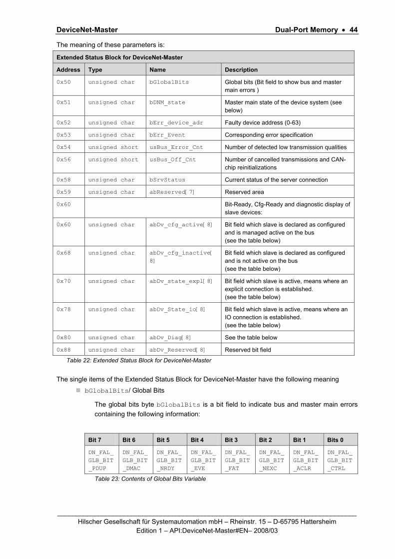
DeviceNet-Master Dual-Port Memory • 44
_________________________________________________________________________________ Hilscher Gesellschaft für Systemautomation mbH – Rheinstr. 15 – D-65795 Hattersheim
Edition 1 – API:DeviceNet-Master#EN– 2008/03
The meaning of these parameters is:
Extended Status Block for DeviceNet-Master
Address Type Name Description
0x50 unsigned char bGlobalBits Global bits (Bit field to show bus and master main errors )
0x51 unsigned char bDNM_state Master main state of the device system (see below)
0x52 unsigned char bErr_device_adr Faulty device address (0-63)
0x53 unsigned char bErr_Event Corresponding error specification
0x54 unsigned short usBus_Error_Cnt Number of detected low transmission qualities
0x56 unsigned short usBus_Off_Cnt Number of cancelled transmissions and CAN-chip reinitializations
0x58 unsigned char bSrvStatus Current status of the server connection
0x59 unsigned char abReserved[7] Reserved area
0x60 Bit-Ready, Cfg-Ready and diagnostic display of slave devices:
0x60 unsigned char abDv_cfg_active[8] Bit field which slave is declared as configured and is managed active on the bus (see the table below)
0x68 unsigned char abDv_cfg_inactive[8]
Bit field which slave is declared as configured and is not active on the bus (see the table below)
0x70 unsigned char abDv_state_expl[8] Bit field which slave is active, means where an explicit connection is established. (see the table below)
0x78 unsigned char abDv_State_io[8] Bit field which slave is active, means where an IO connection is established. (see the table below)
0x80 unsigned char abDv_Diag[8] See the table below
0x88 unsigned char abDv_Reserved[8] Reserved bit field
Table 22: Extended Status Block for DeviceNet-Master
The single items of the Extended Status Block for DeviceNet-Master have the following meaning
bGlobalBits/ Global Bits
The global bits byte bGlobalBits is a bit field to indicate bus and master main errors containing the following information:
Bit 7 Bit 6 Bit 5 Bit 4 Bit 3 Bit 2 Bit 1 Bits 0
DN_FAL_GLB_BIT_PDUP
DN_FAL_GLB_BIT_DMAC
DN_FAL_GLB_BIT_NRDY
DN_FAL_GLB_BIT_EVE
DN_FAL_GLB_BIT_FAT
DN_FAL_GLB_BIT_NEXC
DN_FAL_GLB_BIT_ACLR
DN_FAL_GLB_BIT_CTRL
Table 23: Contents of Global Bits Variable

DeviceNet-Master Dual-Port Memory • 45
_________________________________________________________________________________ Hilscher Gesellschaft für Systemautomation mbH – Rheinstr. 15 – D-65795 Hattersheim
Edition 1 – API:DeviceNet-Master#EN– 2008/03
This bit field serves as a collective display of global notifications. Notified errors can either occur at the device itself or at the slaves. In order to distinguish the different errors the variable bErr_device_adr contains the error location (i.e. bus address), while the variable bErr_Event specifies the corresponding error number. If more than one error is determined, the error location will always show the lowest faulty bus address.
In detail, these bits have the following meaning:
Error type Explanation
DN_FAL_GLB_BIT_CTRL CONTROL-ERROR:
This error is caused by incorrect parameterization.
DN_FAL_GLB_BIT_ACLR AUTO-CLEAR-ERROR:
The device stopped the communication to all slaves and reached the auto-clear end state, i.e. the DeviceNet-Master stopped the communication to all other devices too, if configured to proceed in such a manner.
DN_FAL_GLB_BIT_NEXC NON-EXCHANGE-ERROR:
At least one slave has not reached the data exchange state and no process data are exchanged with it.
DN_FAL_GLB_BIT_FAT FATAL-ERROR:
Because of a severe bus error, no bus communication is possible any more
DN_FAL_GLB_BIT_EVE Bus EVENT ERROR:
A bus error occurred.
DN_FAL_GLB_BIT_NRDY Host-NOT-READY-NOTIFICATION:
Indicates whether the host program has set its state to operative or not. If the bit is set the host program is not ready to communicate
DN_FAL_GLB_BIT_DMAC Duplicate MAC ID
A duplicate MAC ID has been detected
DN_FAL_GLB_BIT_PDUP Process DUPlicate MAC ID
Check duplicate MAC ID in process
Table 24: Error Types in Global Bits
bDNM_state/ DeviceNet Master main state
The master main state represents the operation mode of the DeviceNet-Master stack. This operation mode is defined in section 5.2.2 ”DEVNET_FAL_CMD_SET_MODE_REQ/CNF – Set DeviceNet Operation Mode” of this document. Allowed operation modes are:
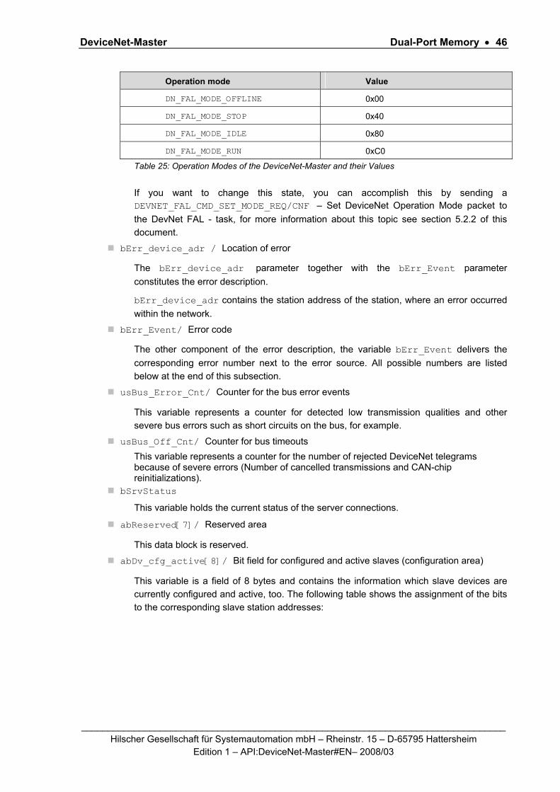
DeviceNet-Master Dual-Port Memory • 46
_________________________________________________________________________________ Hilscher Gesellschaft für Systemautomation mbH – Rheinstr. 15 – D-65795 Hattersheim
Edition 1 – API:DeviceNet-Master#EN– 2008/03
Operation mode Value
DN_FAL_MODE_OFFLINE 0x00
DN_FAL_MODE_STOP 0x40
DN_FAL_MODE_IDLE 0x80
DN_FAL_MODE_RUN 0xC0
Table 25: Operation Modes of the DeviceNet-Master and their Values
If you want to change this state, you can accomplish this by sending a DEVNET_FAL_CMD_SET_MODE_REQ/CNF – Set DeviceNet Operation Mode packet to the DevNet FAL - task, for more information about this topic see section 5.2.2 of this document.
bErr_device_adr / Location of error
The bErr_device_adr parameter together with the bErr_Event parameter constitutes the error description.
bErr_device_adr contains the station address of the station, where an error occurred within the network.
bErr_Event/ Error code
The other component of the error description, the variable bErr_Event delivers the corresponding error number next to the error source. All possible numbers are listed below at the end of this subsection.
usBus_Error_Cnt/ Counter for the bus error events
This variable represents a counter for detected low transmission qualities and other severe bus errors such as short circuits on the bus, for example.
usBus_Off_Cnt/ Counter for bus timeouts This variable represents a counter for the number of rejected DeviceNet telegrams because of severe errors (Number of cancelled transmissions and CAN-chip reinitializations).
bSrvStatus
This variable holds the current status of the server connections.
abReserved[7]/ Reserved area
This data block is reserved.
abDv_cfg_active[8]/ Bit field for configured and active slaves (configuration area)
This variable is a field of 8 bytes and contains the information which slave devices are currently configured and active, too. The following table shows the assignment of the bits to the corresponding slave station addresses:

DeviceNet-Master Dual-Port Memory • 47
_________________________________________________________________________________ Hilscher Gesellschaft für Systemautomation mbH – Rheinstr. 15 – D-65795 Hattersheim
Edition 1 – API:DeviceNet-Master#EN– 2008/03
Bit
Offset
D7 D6 D5 D4 D3 D2 D1 D0
0x60 7 6 5 4 3 2 1 0
0x61 15 14 13 12 11 10 9 8
0x62 23 22 21 20 19 18 17 16
…
0x67 63 62 61 60 59 58 57 56
Table 26: Relationship between Slave Device MAC ID and the corresponding abDv_cfg_active[8] Bit
If the abDv_cfg_active bit of the corresponding slave is logically
'1', the slave is configured in the master, and currently active.
'0', the slave is not configured in the master or currently not active.
abDv_cfg_inactive[8]/ Bit field for configured and inactive slaves (configuration area)
This variable is a field of 8 bytes and contains the information which slave devices are currently configured, but also inactive. The following table shows the assignment of the bits to the corresponding slave station addresses:
Bit
Offset
D7 D6 D5 D4 D3 D2 D1 D0
0x68 7 6 5 4 3 2 1 0
0x69 15 14 13 12 11 10 9 8
0x6A 23 22 21 20 19 18 17 16
…
0x6F 63 62 61 60 59 58 57 56
Table 27: Relationship between Slave Device MAC ID and the corresponding abDv_cfg_inactive[8] Bit
If the abDv_cfg_inactive bit of the corresponding slave is logically
'1', the slave is configured in the master, and currently inactive.
'0', the slave is not configured in the master or currently active

DeviceNet-Master Dual-Port Memory • 48
_________________________________________________________________________________ Hilscher Gesellschaft für Systemautomation mbH – Rheinstr. 15 – D-65795 Hattersheim
Edition 1 – API:DeviceNet-Master#EN– 2008/03
abDv_state_expl[8]/ Bit field for active slave devices where an explicit connection is established
This variable is a field of 8 bytes and contains the information which slave devices are currently active and have established an explicit connection, too. The following table shows, which bit is related to which slave device MAC ID:
Bit
Offset
D7 D6 D5 D4 D3 D2 D1 D0
0x70 7 6 5 4 3 2 1 0
0x71 15 14 13 12 11 10 9 8
0x72 23 22 21 20 19 18 17 16
…
0x77 63 62 61 60 59 58 57 56
Table 28: Relationship between Slave Device MAC ID and the corresponding abDv_state_expl[8] Bit
If the abDv_state_expl bit of the corresponding slave is logically
'1', the slave has established an explicit connection.
'0', the slave has not established an explicit connection.
abDv_State_io[8]/ Bit field for active slave devices where an IO connection is established
This variable is a field of 8 bytes and contains the information which slave devices are currently active and have established an IO connection, too. The following table shows the assignment of the bits to the corresponding slave station addresses:
Bit
Offset
D7 D6 D5 D4 D3 D2 D1 D0
0x78 7 6 5 4 3 2 1 0
0x79 15 14 13 12 11 10 9 8
0x7A 23 22 21 20 19 18 17 16
…
0x7F 63 62 61 60 59 58 57 56
Table 29: Relationship between Slave Device MAC ID and the corresponding abDv_State_io[8] Bit
If the abDv_State_io bit of the corresponding slave is logically
'1', the slave has established an explicit connection.
'0', the slave has not established an explicit connection.

DeviceNet-Master Dual-Port Memory • 49
_________________________________________________________________________________ Hilscher Gesellschaft für Systemautomation mbH – Rheinstr. 15 – D-65795 Hattersheim
Edition 1 – API:DeviceNet-Master#EN– 2008/03
abDv_diag[8] / Slave diagnostic area
This variable is a field of 8 bytes containing the diagnostic bit of each slave. The following table shows the relationship between the device address of the slave and the corresponding bit in the variable abDv_diag.
Bit
Offset
D7 D6 D5 D4 D3 D2 D1 D0
0x80 7 6 5 4 3 2 1 0
0x81 15 14 13 12 11 10 9 8
0x82 23 22 21 20 19 18 17 16
…
0x87 63 62 61 60 59 58 57 56
Table 30: Relationship between Slave Device MAC ID and the corresponding abDv_diag Bit
If the abDv_diag[8] bit of the corresponding slave is logically
'1', newly received diagnostic values are available in the internal diagnostic buffer or one of the diagnostics bit of the device has changed. This data can be read out by the HOST with a message which is described in the chapter 'The message interface' in this manual.
'0', since the last diagnostic buffer read access of the host, no values have been changed in this buffer.
The values in variable abDv_diag are only valid, if the device runs in the main state OPERATE.
abDv_State_io = 0 abDv_State_io = 1
abDv_diag = 0 The device is not operative, no process data exchange between Hilscher master device and slave takes place.
Perhaps this slave is not configured or not able to respond.
Slave device is present on the bus, device guarding is active.
DataIOExchange between Hilscher master device and slave device happens as configured
abDv_diag = 1 The slave device is not operating, device guarding failed or a configuration fault has been detected..
The Hilscher master device provides new diagnostic data in the internal diagnostic buffer to be read out by the host.
The slave device is present on the bus. Device guarding is active and the Hilscher master device and the corresponding slave device exchange their I/O data.
The Hilscher master device provides new diagnostic data in the internal diagnostic buffer to be read out by the host.
Table 31: Relationship between abDv_State_IO bit and abDv_Diag bit
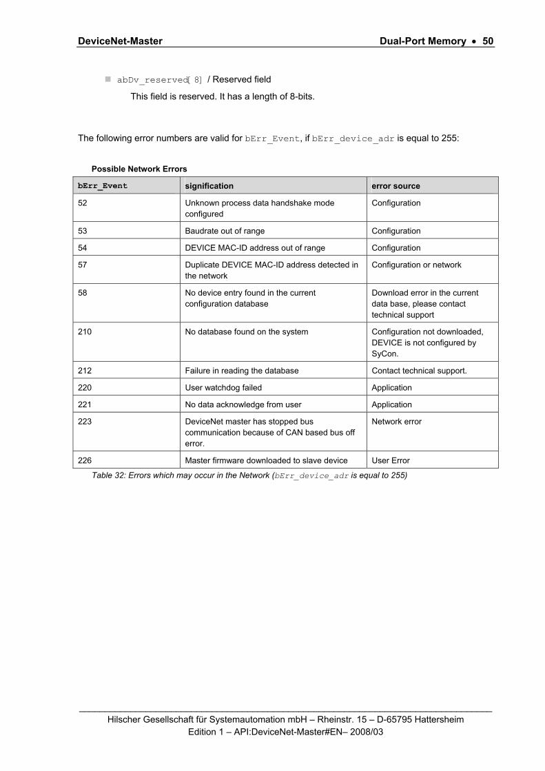
DeviceNet-Master Dual-Port Memory • 50
_________________________________________________________________________________ Hilscher Gesellschaft für Systemautomation mbH – Rheinstr. 15 – D-65795 Hattersheim
Edition 1 – API:DeviceNet-Master#EN– 2008/03
abDv_reserved[8] / Reserved field
This field is reserved. It has a length of 8-bits.
The following error numbers are valid for bErr_Event, if bErr_device_adr is equal to 255:
Possible Network Errors
bErr_Event signification error source
52 Unknown process data handshake mode configured
Configuration
53 Baudrate out of range Configuration
54 DEVICE MAC-ID address out of range Configuration
57 Duplicate DEVICE MAC-ID address detected in the network
Configuration or network
58 No device entry found in the current configuration database
Download error in the current data base, please contact technical support
210 No database found on the system Configuration not downloaded, DEVICE is not configured by SyCon.
212 Failure in reading the database Contact technical support.
220 User watchdog failed Application
221 No data acknowledge from user Application
223 DeviceNet master has stopped bus communication because of CAN based bus off error.
Network error
226 Master firmware downloaded to slave device User Error Table 32: Errors which may occur in the Network (bErr_device_adr is equal to 255)

DeviceNet-Master Dual-Port Memory • 51
_________________________________________________________________________________ Hilscher Gesellschaft für Systemautomation mbH – Rheinstr. 15 – D-65795 Hattersheim
Edition 1 – API:DeviceNet-Master#EN– 2008/03
The following error numbers are valid for bErr_Event, if bErr_device_adr is not equal to 255:
bErr_Event signification error source Remarks/help
0 No error
1 Missing node Device Device guarding failed, after device was operational. Check if device is still running
2 Device has been stopped Device Try to restart the device
30 Device access timeout Device The slave device does not respond, check the baudrate and its MAC-ID
32 Device rejects access with unknown error code
Device Use single device diagnostic to get reject code
35 Device response in allocation phase with connection error
Device Use single device diagnostic to get additional reject code
36 Produced connection ( process data input length in the view of the Hilscher master device) is different to the configured one
Device / configuration Use single device diagnostic to get real produced connection size
37 Consumed connection ( process data output length in the view of the Hilscher master) size is different to the configured one
Device / configuration Use single device diagnostic to get real consumed connection size.
38 Device service response telegram unknown and not handled
Device / Hilscher master device
Use single device diagnostic to get real consumed connection size
39 Connection already in request
Device The connection will be released automatically.
40 Number of CAN-message data bytes in read produced or consumed connection size response unequal 4
Device Device does not have operability with Hilscher master device or it conflicts with the DeviceNet specification.
41 Predefined master slave connection already exists
Device / Hilscher master device
The connection will be released automatically
42 Length in polling device response unequal produced connection size
Device
43 Sequence error in device polling response
Device First two segments in multiplexed transfer were received
44 Fragment error in device Device Fragmentation counter while multiplexed transfer

DeviceNet-Master Dual-Port Memory • 52
_________________________________________________________________________________ Hilscher Gesellschaft für Systemautomation mbH – Rheinstr. 15 – D-65795 Hattersheim
Edition 1 – API:DeviceNet-Master#EN– 2008/03
polling response differs from the awaited one
45 Sequence error in device polling response
Device Middle or last segment was received before the first segment
46 Length in bit strobe device response unequal produced connection size
Device
47 Length in COS or cyclic device response unequal produced connection size
Device
48 Sequence error in device COS or cyclic response
Device Middle or last segment was received before the first segment
49 Fragment error in device COS or cyclic response
Device Fragmentation counter while multiplexed transfer differs from the awaited one
50 Sequence error in device COS or cyclic response
Device First two segments in multiplexed transfer were received
51 UCMM group not supported
Device Change the UCMM group
52 Device Keying failed: Vendor ID mismatch
Device / configuration Check configured Vendor ID against devices Vendor ID
53 Device Keying failed: Device Type mismatch
Device / configuration Check configured Device Type against devices Device Type
54 Device Keying failed: Product Code mismatch
Device / configuration Check configured Product Code against devices Product Code
55 Device Keying failed: Revision mismatch
Device / configuration Check configured Revision against devices Revision
59 Double device address configured in actual configuration
Configuration Each device at DeviceNet must have its own MAC-ID
60
Whole size indicator of one device data set is corrupt Configuration
Download error in the current data base, contact technical support
61
Size of the additional table for predefined master slave connections is corrupt Configuration
Download error in the current data base, contact technical support
62
Size of predefined master slave I/O configuration table is corrupt Configuration
Download error in the current data base, contact technical support
63 Predefined master slave Configuration Number of I/O modules

DeviceNet-Master Dual-Port Memory • 53
_________________________________________________________________________________ Hilscher Gesellschaft für Systemautomation mbH – Rheinstr. 15 – D-65795 Hattersheim
Edition 1 – API:DeviceNet-Master#EN– 2008/03
I/O configuration does not correspond to the additional table
and the number of configured offset addresses are different
64 Size indicator of parameter data table corrupt
Configuration Value of size indicator to small
65 Number of inputs declared in the additional table does not correspond to the number in the I/O configuration table
Configuration Each entry in the I/O configuration must have only one entry in the additional table
66 Number of outputs declared in the additional table does not correspond to the number in the I/O configuration table
Configuration Each entry in the I/O configuration must have only one entry in the additional table
67 Unknown data type in I/O configuration detected
Configuration Support BOOLEAN,BYTE,WO RD,DWORD and STRING only
68 Data type of a defined I/O module in a connection does not correspond with the defined data size
Configuration Following type and size are valid BOOLEAN = 1 byte UINT8 = 1 byte UINT16 = 2byte UINT32 = 4byte
69 Configured output address of one module oversteps the possible address range of 3584 bytes
Configuration The process data image is limited to 3584 bytes
70 Configured input address of one module oversteps the possible address range of 3584 bytes
Configuration The process data image is limited to 3584 bytes
71 One predefined connection type is unknown
Configuration Support of cyclic, polled, change of state, bit strobed only
72 Multiple connections defined in parallel
Configuration Supporting only one type of connection to one device
73 The configured Exp_Packet_Rate value of one connection is less than the Prod_Inhibit_Time value
Configuration Expected packet rate must be larger than the production inhibit time
Table 33: Errors which may occur in the DeviceNet-Master Device (bErr_Rem_Adr is not equal to 255)
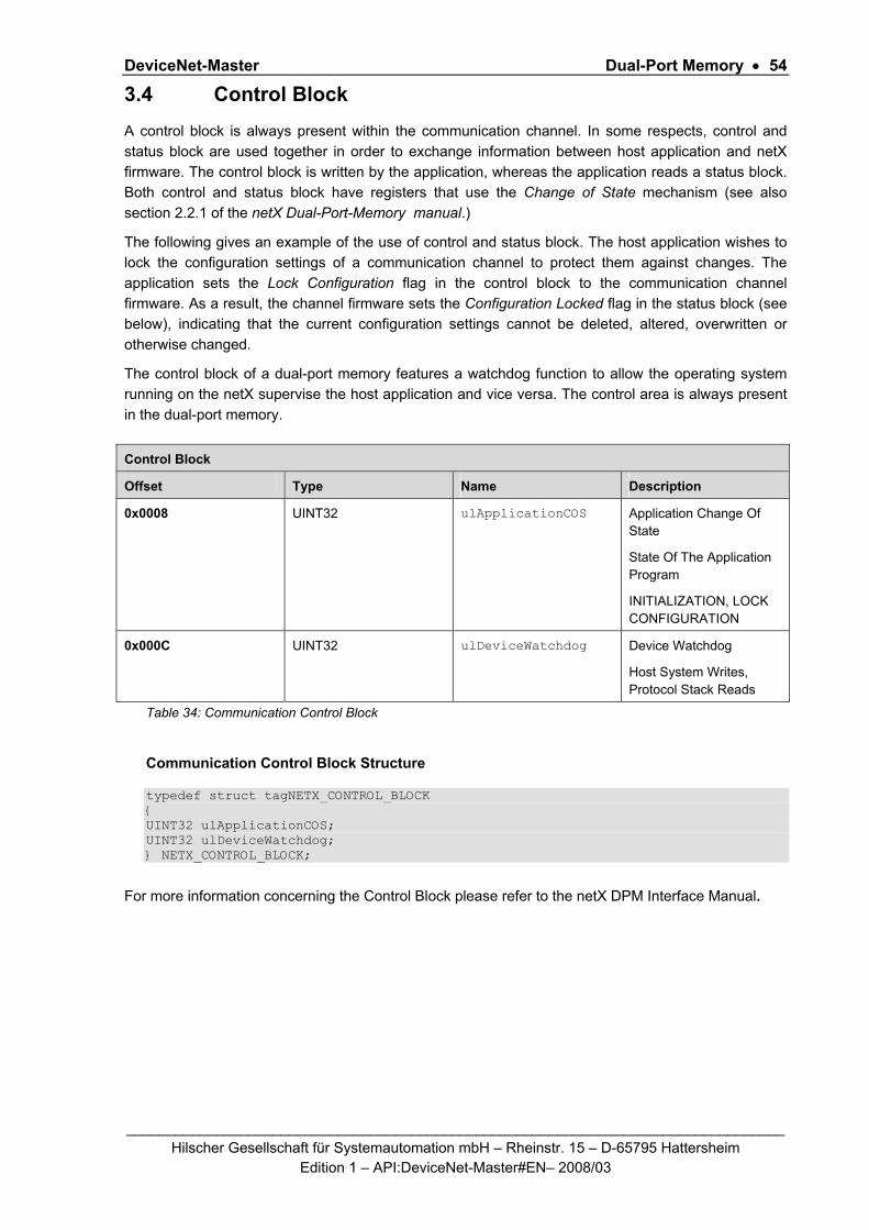
DeviceNet-Master Dual-Port Memory • 54
_________________________________________________________________________________ Hilscher Gesellschaft für Systemautomation mbH – Rheinstr. 15 – D-65795 Hattersheim
Edition 1 – API:DeviceNet-Master#EN– 2008/03
3.4 Control Block A control block is always present within the communication channel. In some respects, control and status block are used together in order to exchange information between host application and netX firmware. The control block is written by the application, whereas the application reads a status block. Both control and status block have registers that use the Change of State mechanism (see also section 2.2.1 of the netX Dual-Port-Memory manual.)
The following gives an example of the use of control and status block. The host application wishes to lock the configuration settings of a communication channel to protect them against changes. The application sets the Lock Configuration flag in the control block to the communication channel firmware. As a result, the channel firmware sets the Configuration Locked flag in the status block (see below), indicating that the current configuration settings cannot be deleted, altered, overwritten or otherwise changed.
The control block of a dual-port memory features a watchdog function to allow the operating system running on the netX supervise the host application and vice versa. The control area is always present in the dual-port memory.
Control Block
Offset Type Name Description
0x0008 UINT32 ulApplicationCOS
Application Change Of State
State Of The Application Program
INITIALIZATION, LOCK CONFIGURATION
0x000C UINT32 ulDeviceWatchdog Device Watchdog
Host System Writes, Protocol Stack Reads
Table 34: Communication Control Block
Communication Control Block Structure typedef struct tagNETX_CONTROL_BLOCK { UINT32 ulApplicationCOS; UINT32 ulDeviceWatchdog; } NETX_CONTROL_BLOCK;
For more information concerning the Control Block please refer to the netX DPM Interface Manual.
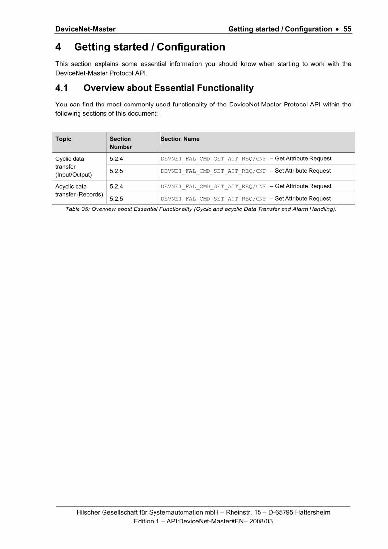
DeviceNet-Master Getting started / Configuration • 55
_________________________________________________________________________________ Hilscher Gesellschaft für Systemautomation mbH – Rheinstr. 15 – D-65795 Hattersheim
Edition 1 – API:DeviceNet-Master#EN– 2008/03
4 Getting started / Configuration This section explains some essential information you should know when starting to work with the DeviceNet-Master Protocol API.
4.1 Overview about Essential Functionality You can find the most commonly used functionality of the DeviceNet-Master Protocol API within the following sections of this document:
Topic Section Number
Section Name
5.2.4 DEVNET_FAL_CMD_GET_ATT_REQ/CNF – Get Attribute Request Cyclic data transfer (Input/Output) 5.2.5 DEVNET_FAL_CMD_SET_ATT_REQ/CNF – Set Attribute Request
5.2.4 DEVNET_FAL_CMD_GET_ATT_REQ/CNF – Get Attribute Request Acyclic data transfer (Records)
5.2.5 DEVNET_FAL_CMD_SET_ATT_REQ/CNF – Set Attribute Request
Table 35: Overview about Essential Functionality (Cyclic and acyclic Data Transfer and Alarm Handling).

DeviceNet-Master Getting started / Configuration • 56
_________________________________________________________________________________ Hilscher Gesellschaft für Systemautomation mbH – Rheinstr. 15 – D-65795 Hattersheim
Edition 1 – API:DeviceNet-Master#EN– 2008/03
4.2 Configuration of Bus, Slave, Server and Device Parameters This section explains how to configure the bus, the master and the slaves correctly. This can be done either by sending packets writing the parameters at the correct places in the dual-port memory or by using Hilscher’s configuration tool SyCon.net. The section introduces both methods and contains a detailed description of all parameters.
4.2.1 Write Access to the Dual-Port Memory
In order to change the configuration parameters for the master in the dual-port memory, a DN_FAL_PACKET_DOWNLOAD_REQ packet has to be sent to the protocol stack. For more information how to accomplish this, please refer to section 5.2.3 of this manual
Similarly, in order to check the currently active parameters, the transfer of parameters can also be performed vice versa. See section 5.2.8 about the DN_FAL_PACKET_UPLOAD_REQ packet.
4.2.2 Using the configuration tool SYCON.NET
The easiest way to configure the DeviceNet-Master is using Hilscher’s configuration tool SyCon.net.
The configuration tool is described in an own manual. See there for more information.

DeviceNet-Master Getting started / Configuration • 57
_________________________________________________________________________________ Hilscher Gesellschaft für Systemautomation mbH – Rheinstr. 15 – D-65795 Hattersheim
Edition 1 – API:DeviceNet-Master#EN– 2008/03
4.3 Detailed Description of DeviceNet Configuration Parameters The configuration parameters of DeviceNet consist of four different Areas, containing the data for
Bus parameters,
Device Parameters,
Slave Parameters and
Server Parameter.
4.3.1 Detailed Description of Bus Parameters
The following table informs about the relevant slave parameters for the DeviceNet-Master firmware such as an explanation of the meaning of the parameter and ranges of allowed values:
Bus Parameters, Meanings and Ranges
Parameter Meaning Range of Values
Communication Auto Release
The start of the device can be performed either application controlled or automatically:
Automatic:
Network connections are opened automatically without taking care of the state of the host application.
Application controlled:
The channel firmware is forced to wait for the host application to set the Application Ready flag in the communication change of state register (see section 3.2.5.1 of the netX DPM Interface Manual).
For more information concerning this topic see section 4.4.1 “Controlled or Automatic Start” of the netX DPM Interface Manual.
Application controlled,
Automatic
I/O Status
(not yet supported)
This parameter is represented by bits 1 and 2 of the system flags.
Using this parameter you can set the status of the input or the output data. For each input and output date the following status information (in byte) is memorized in the dual-port memory.
The bits have the following meaning:
Bit 1 (I/O Status Enable):
0 = Status disabled
1 = Status enabled (not yet supported)
Bit 2 (I/O Status 8/32Bit):
0 = 1 Byte mode (not yet supported)
1 = 4 Byte mode (not yet supported)

DeviceNet-Master Getting started / Configuration • 58
_________________________________________________________________________________ Hilscher Gesellschaft für Systemautomation mbH – Rheinstr. 15 – D-65795 Hattersheim
Edition 1 – API:DeviceNet-Master#EN– 2008/03
Watchdog Time [ms]
Watchdog time within which the device watchdog must be retriggered from the application program while the application program monitoring is activated. When the watchdog time value is equal to 0 respectively the application program monitoring is deactivated.
[0 … 65535] ms, default = 1000 ms, 0 = Off
MAC ID This parameter defines the DeviceNet-Master-Task address of the node (Node ID or MAC ID) within the network.
Allowed values: 0 – 63
Baudrate Baud rate of DeviceNet connection. Coding see Table 37 below!
Allowed values: all baud rates offered in list.
Default value: 0
ConfigFlags Configuration flags Allowed values: 0 – 31
Default value:0
EnableFlags Enable Flags Allowed values: 0x00000000 - 0x0000003F
Reserved There is a reserved area for future extensions 40 Bytes
Table 36: Slave Parameters, their Meanings and their Ranges of allowed Values
4.3.1.1 Watchdog Time
The watchdog time parameter specifies the time in multiples of 1 msec. the device has to supervise the host program if it has started the host-watchdog functionality once. Read in manual 'Toolkit General definitions' how to activate and deactivate the device and host supervision.
4.3.1.2 Own MAC ID Parameter
The Own MAC ID parameter defines the master’s DeviceNet address within the network. Valid choices are in the range from 0 to 63, other values are not allowed by the DeviceNet specification and therefore not supported by the device. Thus they are rejected.
4.3.1.3 Baudrate
The applicable baud rates can be coded according to the values specified in the following table:
Symbolic Name Baud rate Value
DN_FAL_BAUDRATE_500 500 kBit/s 1
DN_FAL_BAUDRATE_250 250 kBit/s 2
DN_FAL_BAUDRATE_125 125 kBit/s 3
Table 37: Available Baud Rate Values

DeviceNet-Master Getting started / Configuration • 59
_________________________________________________________________________________ Hilscher Gesellschaft für Systemautomation mbH – Rheinstr. 15 – D-65795 Hattersheim
Edition 1 – API:DeviceNet-Master#EN– 2008/03
4.3.1.4 Bus Parameter Configuration Flags
The following table shows the meaning of the bus parameter configuration flags byte:
D7 D6 D5 D4 D3 D2 D1 D0 Description
x DN_FAL_MSK_BUS_PRM_CFG_FLAG_AUTOCLEAR
x DN_FAL_MSK_BUS_PRM_CFG_FLAG_INTEL_MOTOROLA
x DN_FAL_MSK_BUS_PRM_CFG_FLAG_CONTINUE_ON_BOI
Table 38: Meaning of Bus Parameter Configuration Flags Byte
If these bits are set to 1, the appropriate item will be activated, otherwise it will be deactivated.
The single bits of the flags variable have the following meaning:
Bit 0 Auto-Clear on/off
This bit defines the behaviour of the DeviceNet-Master if one slave device classified as active has been disconnected.
Value Meaning
1 Active
0 Inactive
Table 39: Meaning of Auto Clear Bit
Active means the DeviceNet-Master stops the communication to all other devices too,
Inactive means the DeviceNet-Master tries to restart the disconnected device and keeps running.
Bit 1 Switch between Intel and Motorola format
Bit 2 Continue on Bus-off (DN_FAL_MSK_BUS_PRM_CFG_FLAG_CONTINUE_ON_BOI):
This flag defines the behavior of the DeviceNet-Master in case a 'bus off' indication from the CAN controller occurs. If the DN_FAL_MSK_BUS_PRM_CFG_FLAG_CONTINUE_ON_BOI flag is set to the value 1 the DeviceNet-Master will continue its operation. Otherwise, the DeviceNet-Master will stop running.
4.3.1.5 EnableFlags
The ‘EnableFlags’ byte decides whether the following identity variables ProductType, ProductCode, MinorRev, MajorRev and the ProductName are filled up with valid data, or not.
However, the value of this flag byte is currently fixed to 0xFFFFFFFF indicating that all identity variables can always be set.

DeviceNet-Master Getting started / Configuration • 60
_________________________________________________________________________________ Hilscher Gesellschaft für Systemautomation mbH – Rheinstr. 15 – D-65795 Hattersheim
Edition 1 – API:DeviceNet-Master#EN– 2008/03
4.3.2 Detailed Description of Slave Parameters
Additionally to the configuration of the bus and the master, also the slaves connected with the master need to be configured.
For each of the up to 64 allowed slaves a data structure is held which allows the administration of each slave.
The details of this complex structure are discussed later in this document in section 5.2.3.3
4.3.3 Detailed Description of Device Parameters Device Parameters, Meanings and Ranges
Parameter Meaning Range of Values
ulConfigFlags Configuration flags Allowed values: 0 – 31
Default value:0
ulEnableFlags Enable Flags Allowed values: 0x00000000 - 0x0000003F
usVendorId Vendor ID 283
(may be changed)
usProductType Product Type 12
usProductCode Product Code Allowed values: 0x0000 - 0xFFFF
Default value:0
bMinorRev Minor Version Allowed values: 0-255 Default value: 1
bMajorRev Major Version Allowed values: 0-255 Default value: 1
ulSerialNumber Serial Number Allowed values: 0x00000000 - 0xFFFFFFFF
abReserved[3] Reserved
bProductNameLen Product Name length Allowed values: 1-32
abProductName[32] Product Name ASCII Characters
abReserved2[8] Reserved
Table 40: Device Parameters, their Meanings and their Ranges of allowed Values
4.3.3.1 Device Parameter ConfigFlags
This flag word is currently reserved and has a fixed value of 0xFFFFFFFF.

DeviceNet-Master Getting started / Configuration • 61
_________________________________________________________________________________ Hilscher Gesellschaft für Systemautomation mbH – Rheinstr. 15 – D-65795 Hattersheim
Edition 1 – API:DeviceNet-Master#EN– 2008/03
4.3.3.2 Device Parameter EnableFlags
The EnableFlags byte decides whether the following identity variables ProductType,
ProductCode,
MinorRev,
MajorRev
and the ProductName
are filled up with valid data, or not.
The following table shows the meaning of the ‘EnableFlags’ byte:
D7 D6 D5 D4 D3 D2 D1 D0 Description
x DN_FAL_MSK_DEV_PRM_ENABLE_VENDORID
x DN_FAL_MSK_DEV_PRM_ENABLE_PRODUCTTYPE
x DN_FAL_MSK_DEV_PRM_ENABLE_PRODUCTCODE
x DN_FAL_MSK_DEV_PRM_ENABLE_MAJORMINORREV
x DN_FAL_MSK_DEV_PRM_ENABLE_SERIALNR
x DN_FAL_MSK_DEV_PRM_ENABLE_PRODUCTNAME
Table 41: Meaning of EnableFlags Byte
If the corresponding bit is set to 1, the variable contains valid data and is enabled, i.e. the appropriate item (Vendor ID, product type, product code, minor and major revision together, serial number and product name) can be set by the user, otherwise this is not possible.
4.3.3.3 VendorId
The VendorId device parameter is a DeviceNet specific unique number which is fixed by the ODVA for each DeviceNet manufacturer. The DeviceNet-Master-Task itself uses this ID during the Duplicate MAC-ID check phase and within each sent Duplicate MAC-Id check response. The value range of this variable is not limited. The Hilscher ID is 283 (decimal).
This value is related to the Vendor ID Attribute of the Identity Object, see section 1.4.2.1.
4.3.3.4 ProductType
The ProductType device parameter is the indication of the general type of product. The Hilscher standard value for this is 12 which represents a Communications Adapter.
This value is related to the Device Type Attribute of the Identity Object, see section 1.4.2.1.
4.3.3.5 ProductCode

DeviceNet-Master Getting started / Configuration • 62
_________________________________________________________________________________ Hilscher Gesellschaft für Systemautomation mbH – Rheinstr. 15 – D-65795 Hattersheim
Edition 1 – API:DeviceNet-Master#EN– 2008/03
The ProductCode device parameter is the identification of a particular product within a defined device type.
This value is related to the Product Code Attribute of the Identity Object, see section 1.4.2.1
4.3.3.6 MinorRev
The MinorRev device parameter is one part of the revision which identifies the revision of the DNM device. The revision attribute consists of Major and Minor Revisions and they are typically displayed as major.minor.
This value is related to the Minor Revision Attribute of the Identity Object, see section 1.4.2.1
4.3.3.7 MajorRev
The MajorRev device parameter is the second part of the revision. The Major Revision attribute is limited to 7 bits. The eighth bit is reserved by DeviceNet and must have a default value of zero.
This value is related to the Major Revision Attribute of the Identity Object, see section 1.4.2.1.
4.3.3.8 SerialNumber
The SerialNumber device parameter is the eight byte serial number of the user created device. It should be unique.
This value is related to the Serial Number Attribute of the Identity Object, see section 1.4.2.1.
4.3.3.9 ProductNameLen
The ProductNameLen device parameter is the length of ProdName. The maximum number of characters in this string is 32.
4.3.3.10 ProductName[32]
The ProdName device parameter is a text string that should represent a short description of the product/product family. The maximum number of characters in this string is 32.
The number of characters must be set in parameter ProdNameLen.
This value is related to the Product Name Attribute of the Identity Object, see section 1.4.2.1.

DeviceNet-Master Getting started / Configuration • 63
_________________________________________________________________________________ Hilscher Gesellschaft für Systemautomation mbH – Rheinstr. 15 – D-65795 Hattersheim
Edition 1 – API:DeviceNet-Master#EN– 2008/03
4.3.4 Detailed Description of Server Parameters
Additionally to its client functionality, a DeviceNet-Master also offers server functionality for master-to-master communication. This server functionality also needs to be configured. It can be activated by setting at least one of the two parameters SrvConsConnSize and SrvProdConnSize to a non-zero value. Vice versa, setting both values to 0 inhibits the master-to-master communication.
The following table informs about the relevant server parameters for the DeviceNet-Master firmware such as an explanation of the meaning of the parameter and ranges of allowed values:
Slave Parameters, Meanings and Ranges
Parameter Meaning Range of Values
SrvConsConnSize
Consumed I/O connection size as server 0 - 255
ConsOffset Offset address in input area for server input data 0 - 3583
SrvProdConnSize
Produced I/O connection size as server 0 - 255
ProdOffset Offset address in output area for server output data 0 - 3583
Table 42: Slave Parameters, their Meanings and their Ranges of allowed Values
4.3.4.1 SrvConsConnSize
This parameter allows to specify the length of the data area within the input buffer to be used for the master-to-master information exchange.
It relates to the Consumed Connection Size attribute of the Connection object, see section 1.4.2.4 for more information.
4.3.4.2 ConsOffset
If a non-zero value is specified for SrvConsConnSize information is required where in the IO area to store the input data. This parameter allows to specify where (i.e. at which offset) in the input buffer the data area for the master-to-master information exchange begins.
4.3.4.3 SrvProdConnSize
This parameter allows to specify the length of the data area within the output buffer to be used for the master-to-master information exchange.
This parameter relates to the Produced Connection Size attribute of the Connection object, see section 1.4.2.4 for more information.
4.3.4.4 ProdOffset
If a non-zero value is specified for SrvConsConnSize information is required where in the IO area to store the output data. This parameter allows to specify where (i.e. at which offset) in the output buffer the data area for the master-to-master information exchange begins.

DeviceNet-Master The DeviceNet Application Interface • 64
_________________________________________________________________________________ Hilscher Gesellschaft für Systemautomation mbH – Rheinstr. 15 – D-65795 Hattersheim
Edition 1 – API:DeviceNet-Master#EN– 2008/03
5 The DeviceNet Application Interface This chapter defines the user application interface of the DeviceNet Stack. There are two different levels the user can access the DeviceNet stack.
The Communication Channel Interface
The DeviceNetFAL - Task Interface
The Communication Channel Interface is the Hilscher’s Dual port Memory Interface for field buses or other communication stacks. A typical application is when using PC cards or COM modules with a discrete DPM and accessing the DeviceNet via Driver API. This Interface is also available, when a user develops its own application within the netX system and works with the virtual DPM system intern.
The second level is when a user implements its own application task direct over the DevNetFAL Task. Then a user has to care the configuration process, mapping I/O data and status information by its own. Typically when a user works with its own dual port memory layout. The application itself has to be developed then as a task according to the Hilscher’s Task Layer Reference Model.
5.1 The DevNet AP - Task Within the DeviceNet Stack the DevNetAP - Task is an Application Layer on Top of the DeviceNetFAL - Task itself. It is responsible for transferring the I/O, diagnostic and acyclic data from and to the DeviceNet FAL Task on the one hand and the Dual port Interface on the other hand. Furthermore, the DeviceNetAP Task is responsible for all user application interactions and represents the one and only counterpart of the user within the existent DeviceNet-Stack implementation.
To get the handle of the process queue of the DevNetAP -Task the Macro TLR_QUE_IDENTIFY() has to be used in conjunction with the following ASCII-Queue name
ASCII Queue name Description
"QUE_DEVNET_AP” Name of the DevNetAP -Task process queue Table 43: DevNetAP-Task Process Queue
The returned handle has to be used as value ulDest in all initiator packets the user intends to send to the DevNetAP -Task. This handle is the same handle that has to be used in conjunction with the macros like TLR_QUE_SENDPACKET_FIFO/LIFO() for sending a packet to the DevNetAP -Task.

DeviceNet-Master The DeviceNet Application Interface • 65
_________________________________________________________________________________ Hilscher Gesellschaft für Systemautomation mbH – Rheinstr. 15 – D-65795 Hattersheim
Edition 1 – API:DeviceNet-Master#EN– 2008/03
5.1.1 Handled Commands
The DevNetAP - Task itself has no own commands. But the DevNetAP Task knows all the commands from the underlying DeviceNet Stack and the Common Global task commands. The AP Task will route the commands to the appropriate Task. The AP task will not route the full command set of the underlying DeviceNet stack and in every state. The reason is, that the AP-Task handles some control commands of the underlying stack by its own automatic, and the it is not allowed for the user to execute these commands. Also it depends on the current implementation status of the FW.
The list of all currently handled and not handled (rejected) commands is as follows:
Commands Handled
Description
Common Global Stack Commands
DIAG_INFO_GET_COMMON_STATE_REQ yes Returns the common status information that is the same for all communication channels
DIAG_INFO_GET_EXTENDED_STATE_RE
Q
yes Returns the DeviceNet specific status information of the extended status block
CONFIGURATION_RELOAD_REQ yes Indication when new configuration is available, cause a reset of the DeviceNet stack,
DeviceNetFAL Task specific Commands
DEVNET_FAL_CMD_INIT_REQ yes Cause a reset/initialization of the DeviceNet stack
DEVNET_FAL_CMD_DOWNLOAD_REQ yes Download configuration data
DEVNET_FAL_CMD_GET_ATT_REQ yes DeviceNet Get Attribute Service
DEVNET_FAL_CMD_SET_ATT_REQ yes DeviceNet Set Attribute Service
DEVNET_FAL_CMD_ACYC_BTS_REQ yes Acyclic Bit-strobe
DEVNET_FAL_CMD_LIFELIST_REQ yes Generate Lifelist
DEVNET_FAL_CMD_UPLOAD_REQ yes Parameter Upload
DEVNET_FAL_CMD_SET_MODE_REQ no (Rejected)
The operation mode is controlled via the “HostReady” flag of the communication channel
CAN DL Task specific Commands
CAN_DL_CMD_ … no (Rejected)
All CAN commands are rejected from the AP task. The user has no access to the CAN layer.
Table 44: DeviceNet-Master - Handled Commands

DeviceNet-Master The DeviceNet Application Interface • 66
_________________________________________________________________________________ Hilscher Gesellschaft für Systemautomation mbH – Rheinstr. 15 – D-65795 Hattersheim
Edition 1 – API:DeviceNet-Master#EN– 2008/03
5.1.2 Extended Status Information
The DeviceNet stack uses the extended status field within the communication channel to transfer following status information. The AP task is responsible to map this information into the extended status block of the communication channel. To obtain these information the user can send the global command DIAG_INFO_GET_EXTENDED_STATE_REQ to the AP task or call the appropriate cifX DriverAPI function when accessing to the communication channel via driver. In its current implementation the extended status field DEVNET_AP_EXT_STATUS_T contains one structure “tGlobalStateFiled”. In future in can maybe enlarged by adding additional diagnostic structures if necessary.
Structure Reference
You can find a detailed structure reference of structure “DN_FAL_EXT_DIAG_T tGlobalStateFiled” in section 3.3.2 “Extended Status”.
The established structure “DN_FAL_EXT_DIAG_T tGlobalStateFiled” informs about global bus states as well as individual states of the managed devices. To hold the information preferably compact, the device specific informations are stated in bit fields.
For a detailed discussion of the meaning of all these variables and bit fields also refer to section 3.3.2.
5.2 The DevNet FAL - Task Within the DeviceNet Stack the DevNetFAL-Task co-ordinates the underlying Slave state machines used for processing of the various services.
Furthermore, it is responsible for all application interactions and represents the counterpart of the AP-Task within the existent DeviceNet Stack implementation.
To get the handle of the process queue of the DevNetFAL -Task the Macro TLR_QUE_IDENTIFY() has to be used in conjunction with the following ASCII-Queue name
ASCII Queue name Description
"DEVNET_FAL_QUE” Name of the DevNetFAL -Task process queue Table 45: DevNetFAL-Task Process Queue
The returned handle has to be used as value ulDest in all initiator packets the AP-Task intends to send to the DevNetFAL -Task. This handle is the same handle that has to be used in conjunction with the macros like TLR_QUE_SENDPACKET_FIFO/LIFO() for sending a packet to the DevNetFAL -Task.

DeviceNet-Master The DeviceNet Application Interface • 67
_________________________________________________________________________________ Hilscher Gesellschaft für Systemautomation mbH – Rheinstr. 15 – D-65795 Hattersheim
Edition 1 – API:DeviceNet-Master#EN– 2008/03
5.2.1 DEVNET_FAL_CMD_INIT_REQ/CNF – Initialize the DeviceNet Stack
The initialization request is used to force the DeviceNet protocol stack into a determined state. e.g. to resetting the stack. The mode of the init command determines the method and initialization action.
Packet Structure Reference
#define DN_FAL_INIT_MODE_RESET 0x00000000 /* Reset same as after a power on*/ typedef struct DN_FAL_SDU_INIT_REQ_Ttag { TLR_UINT32 ulMode; } DN_FAL_SDU_INIT_REQ_T; typedef struct DN_FAL_PACKET_INIT_REQ_Ttag { TLR_PACKET_HEADER_T tHead; DN_FAL_SDU_INIT_REQ_T tData; } DN_FAL_PACKET_INIT_REQ_T;
Packet Description
structure DN_FAL_PACKET_INIT_REQ_T
Type: Request
Area Variable Type Value / Range Description
Head structure TLR_PACKET_HEADER_T
ulDest UINT32 Destination Queue-Handle
ulSrc UINT32 Source Queue-Handle of AP-Task Process Queue
ulDestId UINT32 0 Destination End Point Identifier, specifying the final receiver of the packet within the Destination Process. Set to 0 for the Initialization Packet
ulSrcId UINT32 0 ... 232-1 Source End Point Identifier, specifying the origin of the packet inside the Source Process
ulLen UINT32 4 sizeof(DN_FAL_SDU_INIT_REQ_T)
ulId UINT32 0 ... 232-1 Packet Identification as unique number generated by the Source Process of the Packet
ulSta UINT32 0
ulCmd UINT32 0x3800 DEVNET_FAL_CMD_INIT_REQ - Command
ulExt UINT32 0 Extension not in use, set to zero for compatibility reasons
ulRout UINT32 0 Routing, set to zero
Data structure DN_FAL_SDU_INIT_REQ_T
ulMode UINT32 0 DN_FAL_INIT_MODE_RESET
Table 46: DN_FAL_CMD_INIT_REQ – Request Command for DN Init

DeviceNet-Master The DeviceNet Application Interface • 68
_________________________________________________________________________________ Hilscher Gesellschaft für Systemautomation mbH – Rheinstr. 15 – D-65795 Hattersheim
Edition 1 – API:DeviceNet-Master#EN– 2008/03
Source Code Example
TLR_RESULT DnUser_StackReset_Req(DN_USER_RSC_T FAR* ptRsc) { TLR_RESULT eRslt; DN_FAL_PACKET_INIT_REQ_T *ptInitReq; eRslt = TLR_POOL_PACKET_GET(ptRsc->tLoc.hPool, &ptInitReq); if( eRslt == TLR_S_OK ) { TLR_QUE_LINK_SET_PACKET_SRC(ptRegAppReq,ptRsc->tLoc.tQueSrcDnApp); ptInitReq->tHead.ulCmd = DEVNET_FAL_CMD_INIT_REQ; ptInitReq->tHead.ulLen = sizeof(ptInitReq->tData); /* Set the reset mode */ ptRegAppReq->tData.ulMode = DN_FAL_INIT_MODE_RESET; eRslt = TLR_QUE_SENDPACKET_FIFO(ptRsc->tLoc.tDnFalQue,ptInit,TLR_FINITE); if( eRslt != TLR_S_OK ) { TLR_POOL_PACKET_RELEASE(ptRsc->tLoc.hPool, ptInitReq); } } return eRslt; }

DeviceNet-Master The DeviceNet Application Interface • 69
_________________________________________________________________________________ Hilscher Gesellschaft für Systemautomation mbH – Rheinstr. 15 – D-65795 Hattersheim
Edition 1 – API:DeviceNet-Master#EN– 2008/03
Packet Structure Reference
typedef struct DN_FAL_SDU_INIT_CNF_Ttag { TLR_UINT32 ulMode; } DN_FAL_SDU_INIT_CNF_T; typedef struct DN_FAL_PACKET_INIT_CNF_Ttag { TLR_PACKET_HEADER_T tHead; DN_FAL_SDU_INIT_CNF_T tData; } DN_FAL_PACKET_INIT_CNF_T;
Packet Description
structure DN_FAL_PACKET_INIT_CNF_T
Type: Confirmation
Area Variable Type Value / Range Description
Head structure TLR_PACKET_HEADER_T
ulDest UINT32 Destination Queue-Handle, untouched
ulSrc UINT32 Source Queue-Handle, untouched
ulDestId UINT32 0 Destination End Point Identifier, untouched
ulSrcId UINT32 0 ... 232-1 Source End Point Identifier, untouched
ulLen UINT32 4 sizeof(DN_FAL_SDU_INIT_CNF_T)
ulId UINT32 0 ... 232-1 Packet Identification, untouched
ulSta UINT32 See Table 48: DEVNET_FAL_CMD_INIT_CNF – Packet Status/Error
ulCmd UINT32 0x3801 DEVNET_FAL_CMD_INIT_CNF - Command
ulExt UINT32 0 Extension, untouched
ulRout UINT32 × Routing, do not touch
Data structure DN_FAL_SDU_INIT_CNF_T
ulMode UINT32 x returned, untouched
Table 47: DEVNET_FAL_CMD_INIT_CNF – Confirmation of Init Request

DeviceNet-Master The DeviceNet Application Interface • 70
_________________________________________________________________________________ Hilscher Gesellschaft für Systemautomation mbH – Rheinstr. 15 – D-65795 Hattersheim
Edition 1 – API:DeviceNet-Master#EN– 2008/03
Packet Status/Error
Definition / (Value) Description
TLR_S_OK (0x00000000)
Initialization successful.
TLR_E_DEVNET_FAL_UNRECOVER_RESET_FAULT (0xC0470004)
Something failed during reset. This is an fatal error. To recover this state a device reset is necessary.
TLR_E_DEVNET_FAL_CLR_CONFIG_NOT_ALLOWED_IN_ACTUAL_STATE (0xC0470020)
The configuration “Look” bit is set, or the Stack is in Operate mode
Table 48: DEVNET_FAL_CMD_INIT_CNF – Packet Status/Error

DeviceNet-Master The DeviceNet Application Interface • 71
_________________________________________________________________________________ Hilscher Gesellschaft für Systemautomation mbH – Rheinstr. 15 – D-65795 Hattersheim
Edition 1 – API:DeviceNet-Master#EN– 2008/03
5.2.2 DEVNET_FAL_CMD_SET_MODE_REQ/CNF – Set DeviceNet Operation Mode
The command DEVNET_FAL_CMD_SET_MODE_REQ is used to set the operational mode of the DevNetFAL -Task.
Valid modes are:
OFFLINE
- The DeviceNet Master is not active on network, and is not accessible for other devices.
STOP - The DeviceNet Master performs the Duplicate-MAC Id check procedure, but does not start any I/O communication. The master is accessible for other devices with explicite. messaging
IDLE - Currently same as RUN
RUN - The DeviceNet Master starts I/O communication to all configured slaves.
Packet Structure Reference
#define DN_FAL_MODE_OFFLINE (0x00) #define DN_FAL_MODE_STOP (0x40) #define DN_FAL_MODE_IDLE (0x80) #define DN_FAL_MODE_RUN (0xC0) typedef struct DN_FAL_SDU_SET_MODE_REQ_Ttag { TLR_UINT32 ulMode; } DN_FAL_SDU_SET_MODE_REQ_T; typedef struct DN_FAL_PACKET_SET_MODE_REQ_Ttag { TLR_PACKET_HEADER_T tHead; DN_FAL_SET_MODE_REQ_T tData; } DN_FAL_PACKET_SET_MODE_REQ_T;
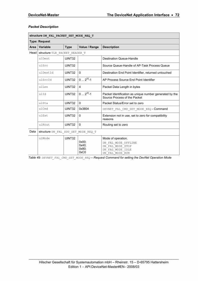
DeviceNet-Master The DeviceNet Application Interface • 72
_________________________________________________________________________________ Hilscher Gesellschaft für Systemautomation mbH – Rheinstr. 15 – D-65795 Hattersheim
Edition 1 – API:DeviceNet-Master#EN– 2008/03
Packet Description
structure DN_FAL_PACKET_SET_MODE_REQ_T
Type: Request
Area Variable Type Value / Range Description
Head structure TLR_PACKET_HEADER_T
ulDest UINT32 Destination Queue-Handle
ulSrc UINT32 Source Queue-Handle of AP-Task Process Queue
ulDestId UINT32 0 Destination End Point Identifier, returned untouched
ulSrcId UINT32 0 ... 232-1 AP Process Source End Point Identifier
ulLen UINT32 4 Packet Data Length in bytes
ulId UINT32 0 ... 232-1 Packet Identification as unique number generated by the Source Process of the Packet
ulSta UINT32 0 Packet Status/Error set to zero
ulCmd UINT32 0x3804 DEVNET_FAL_CMD_SET_MODE_REQ - Command
ulExt UINT32 0 Extension not in use, set to zero for compatibility reasons
ulRout UINT32 0 Routing set to zero
Data structure DN_FAL_SDU_SET_MODE_REQ_T
ulMode UINT32 0x00; 0x40; 0x80; 0xC0
Mode of operation. DN_FAL_MODE_OFFLINE DN_FAL_MODE_STOP DN_FAL_MODE_IDLE DN_FAL_MODE_RUN
Table 49: DEVNET_FAL_CMD_SET_MODE_REQ – Request Command for setting the DevNet Operation Mode

DeviceNet-Master The DeviceNet Application Interface • 73
_________________________________________________________________________________ Hilscher Gesellschaft für Systemautomation mbH – Rheinstr. 15 – D-65795 Hattersheim
Edition 1 – API:DeviceNet-Master#EN– 2008/03
Source Code Example
TLR_RESULT DnUser_Stop_Req(DN_USER_RSC_T FAR* ptRsc) { TLR_RESULT eRslt = TLR_S_OK; DN_FAL_PACKET_SET_MODE_REQ_T *ptSetModeReq = NULL; eRslt = TLR_POOL_PACKET_GET(ptRsc->tLoc.hPool, & ptSetModeReq); if( eRslt == TLR_S_OK ) { TLR_QUE_LINK_SET_PACKET_SRC(ptSetModeReq,ptRsc->tLoc.tQueSrcApp); ptSetModeReq->tHead.ulCmd = DEVNET_FAL_CMD_SET_MODE_REQ; ptSetModeReq->tHead.ulLen = sizeof(DN_FAL_SDU_SET_MODE_REQ_T); /* Set the mode to stop */ ptSetModeReq->tData.ulMode = DN_FAL_MODE_STOP; eRslt = TLR_QUE_SENDPACKET_FIFO(ptRsc->tLoc.tDstQue,ptSetModeReq,TLR_FINITE); if( eRslt != TLR_S_OK ) { TLR_POOL_PACKET_RELEASE(ptRsc->tLoc.hPool, ptInitReq); } } return eRslt; }

DeviceNet-Master The DeviceNet Application Interface • 74
_________________________________________________________________________________ Hilscher Gesellschaft für Systemautomation mbH – Rheinstr. 15 – D-65795 Hattersheim
Edition 1 – API:DeviceNet-Master#EN– 2008/03
Packet Structure Reference
typedef struct DN_FAL_SDU_SET_MODE_CNF_Ttag { TLR_UINT32 ulMode; } DN_FAL_SDU_SET_MODE_CNF_T; typedef struct DN_FAL_PACKET_SET_MODE_CNF_Ttag { TLR_PACKET_HEADER_T tHead; DN_FAL_SDU_SET_MODE_CNF_T tData; } DN_FAL_PACKET_SET_MODE_CNF_T;
Packet Description
structure DN_FAL_PACKET_SET_MODE_CNF_T
Type: Confirmation
Area Variable Type Value / Range Description
Head structure TLR_PACKET_HEADER_T
ulDest UINT32 Destination Queue-Handle, returned untouched
ulSrc UINT32 Source Queue-Handle of AP Process Queue, returned untouched
ulDestId UINT32 0 Destination End Point Identifier, returned untouched
ulSrcId UINT32 0 ... 232-1 AP Process Source End Point Identifier, returned untouched
ulLen UINT32 4 Packet Data Length in bytes
ulId UINT32 0 ... 232-1 Packet Identification, untouched
ulSta UINT32 0 ... 232-1 See Table 51: DEVNET_FAL_CMD_SET_MODE_CNF – Packet Status/Error
ulCmd UINT32 0x3805 DEVENT_FAL_CMD_SET_MODE_CNF - Command
ulExt UINT32 0 Extension, untouched
ulRout UINT32 × Routing, do not touch
Data structure DN_FAL_SET_MODE_CNF_T
ulMode UINT32 0 .. 3 Confirmation of mode set.
DN_FAL_MODE_OFFLINE DN_FAL_MODE_STOP DN_FAL_MODE_IDLE DN_FAL_MODE_RUN
Table 50: DEVNET_FAL_CMD_SET_MODE_CNF – Confirmation of DN Set Mode Command

DeviceNet-Master The DeviceNet Application Interface • 75
_________________________________________________________________________________ Hilscher Gesellschaft für Systemautomation mbH – Rheinstr. 15 – D-65795 Hattersheim
Edition 1 – API:DeviceNet-Master#EN– 2008/03
Packet Status/Error
Definition / (Value) Description
TLR_S_OK (0x00000000)
Initialization successful.
TLR_E_DEVNET_FAL_SET_MODE_INVALID_MODE (0xC0470010)
Invalid value for 'mode' of command.
TLR_E_DEVNET_FAL_SET_MODE_ALREADY_IN_REQUEST (0xC0470011)
Command already in request.
Table 51: DEVNET_FAL_CMD_SET_MODE_CNF – Packet Status/Error

DeviceNet-Master The DeviceNet Application Interface • 76
_________________________________________________________________________________ Hilscher Gesellschaft für Systemautomation mbH – Rheinstr. 15 – D-65795 Hattersheim
Edition 1 – API:DeviceNet-Master#EN– 2008/03
5.2.3 DEVNET_FAL_CMD_DOWNLOAD_REQ/CNF – Download DeviceNet Configuration
The command DEVNET_FAL_CMD_DOWNLOAD_REQ is used to download a configuration to the DeviceNet stack. The download is divided into so called areas like slave parameter sets or the bus parameter set.
The download needs to be done in following order:
DN_FAL_DOWNLOAD_AREA_DEVICE_PARAMETER
DN_FAL_DOWNLOAD_AREA_SERVER_PARAMETER (optional)
DN_FAL_DOWNLOAD_AREA_SLAVE_PARAMETER
DN_FAL_DOWNLOAD_AREA_BUS_PARAMETER
The download of the bus parameters finishes the configuration process.
Packet Structure Reference
#define DN_FAL_DOWNLOAD_AREA_BUS_PARAMETER (0) #define DN_FAL_DOWNLOAD_AREA_SLAVE_PARAMETER (1) #define DN_FAL_DOWNLOAD_AREA_SERVER_PARAMETER (2) #define DN_FAL_DOWNLOAD_AREA_DEVICE_PARAMETER (3) typedef struct DN_FAL_SDU_DOWNLOAD_REQ_Ttag { TLR_UINT16 usArea; TLR_UINT16 usSubArea; TLR_UINT8 abData[1000]; } DN_FAL_SDU_DOWNLOAD_REQ_T; typedef struct DN_FAL_PACKET_DOWLOAD_REQ_Ttag { TLR_PACKET_HEADER_T tHead; DN_FAL_SDU_DOWNLOAD_REQ_T tData; } DN_FAL_PACKET_DOWNLOAD_REQ_T;

DeviceNet-Master The DeviceNet Application Interface • 77
_________________________________________________________________________________ Hilscher Gesellschaft für Systemautomation mbH – Rheinstr. 15 – D-65795 Hattersheim
Edition 1 – API:DeviceNet-Master#EN– 2008/03
Packet Description
structure DN_FAL_PACKET_DOWNLOAD_REQ_T
Type: Request
Area Variable Type Value / Range Description
Head structure TLR_PACKET_HEADER_T
ulDest UINT32 Destination Queue-Handle
ulSrc UINT32 Source Queue-Handle of AP-Task Process Queue
ulDestId UINT32 0 Destination End Point Identifier set to zero
ulSrcId UINT32 0 ... 232-1 AP Process Source End Point Identifier
ulLen UINT32 4 + n Packet Data Length in bytes
DN_FAL_DOWNLOAD_REQ_SIZE + n = number of download data in bytes in abData[ … ]
ulId UINT32 0 ... 232-1 Packet Identification as unique number generated by the Source Process of the Packet
ulSta UINT32 0 Packet Status/Error set to zero
ulCmd UINT32 0x3802 DEVNET_FAL_CMD_DOWNLOAD_REQ - Command
ulExt UINT32 x Sequence information. TLR_PACKET_SEQ_NONE TLR_PACKET_SEQ_FIRST TLR_PACKET_SEQ_MIDDLE TLR_PACKET_SEQ_LAST
ulRout UINT32 0 Routing, set to zero
Data structure DN_FAL_SDU_DOWNLOAD_REQ_T
usArea UINT16 0..3 Area code of where the data is to be downloaded.
DN_FAL_DOWNLOAD_AREA_BUS_PARAMETER DN_FAL_DOWNLOAD_AREA_SLAVE_PARAMETER DN_FAL_DOWNLOAD_AREA_SERVER_PARAMETER DN_FAL_DOWNLOAD_AREA_DEVICE_PARAMETER
usSubArea UINT16 0..n depends on usArea
…_AREA_BUS_PARAMETER 0 …_AREA_SLAVE_PARAMETER 0..63 ( Mac ID ) …_AREA_SERVER_PARAMETER 0 …_AREA_DEVICE_PARAMETER 0
abData [0..1000]
UINT8[] xxx Download data contents depends on usArea
Table 52: DEVNET_FAL_CMD_DOWNLOAD_REQ – Request Command for Configuration Download

DeviceNet-Master The DeviceNet Application Interface • 78
_________________________________________________________________________________ Hilscher Gesellschaft für Systemautomation mbH – Rheinstr. 15 – D-65795 Hattersheim
Edition 1 – API:DeviceNet-Master#EN– 2008/03
Source Code Example: Complete Configuration Procedure
TLR_RESULT DnUser_Download_Configuration(DN_USER_RSC_T FAR* ptRsc) { TLR_RESULT eRslt = TLR_S_OK; TLR_UINT8 *pabDownData = NULL; DN_FAL_DEV_PRM_T tDevPrm; DN_FAL_SRV_PRM_T tSrvPrm; DN_FAL_BUS_PRM_T tBusPrm; TLR_UINT8 *pabSlvPrm; TLR_UINT32 ulSlvPrmLen; InitDeviceParameter(&tDevPrm); //See source example below InitServerParameter(&tSrvPrm); //See source example below InitBusParameter(&tBusPrm); //See source example below InitGetSlaveParameter(2,&pabSlvPrm,&ulSlvPrmLem); //See source example below for( ulDownPrm = 0; ulDownPrm < 4; ulDownPrm++ ) { switch( ulDownPrm ) { case 0: //Download Device Parameter { pabDownData = (TLR_UINT8*)&tDevPrm; ulDownLen = sizeof(DN_FAL_DEV_PRM_T); usDownArea = DN_FAL_DOWNLOAD_AREA_DEVICE_PARAMETER; usDownSubArea = 0; } break; case 1: //Download Server Parameter { pabDownData = (TLR_UINT8*)&tSrvPrm; ulDownLen = sizeof(DN_FAL_DEV_PRM_T); usDownArea = DN_FAL_DOWNLOAD_AREA_SERVER_PARAMETER; usDownSubArea = 0; break; } case 2: //Download one Slave Parameter set { pabDownData = (TLR_UINT8*)&abSlvPrm; ulDownLen = sizeof(abSlvPrm); usDownArea = DN_FAL_DOWNLOAD_AREA_SLAVE_PARAMETER; usDownSubArea = 2; // Device address 2 break; } case 3: //Download Bus Parameter { pabDownData = (TLR_UINT8*)&tBusPrm; ulDownLen = sizeof(DN_FAL_BUS_PRM_T); usDownArea = DN_FAL_DOWNLOAD_AREA_BUS_PARAMETER; usDownSubArea = 0; break; } } } //See source example below for this function eRslt = DnUser_Download( ptRsc, pabDownData, ulDownLen, usDownArea, usDownSubArea ); if(eRslt != TLR_S_OK ) { break; //for } return eRslt; }

DeviceNet-Master The DeviceNet Application Interface • 79
_________________________________________________________________________________ Hilscher Gesellschaft für Systemautomation mbH – Rheinstr. 15 – D-65795 Hattersheim
Edition 1 – API:DeviceNet-Master#EN– 2008/03
Source Code Example: Download Configuration Data
TLR_RESULT DnUser_Download( DN_USER_RSC_T FAR* ptRsc, TLR_UINT8 *pabData, TLR_UINT32 ulLen, TLR_UINT16 usArea, TLR_UINT16 usSubArea ) { TLR_RESULT eRslt = TLR_S_OK; DN_FAL_PACKET_DOWNLOAD_REQ_T *ptDownReq = NULL; eRslt = TLR_POOL_PACKET_GET(ptRsc->tLoc.hPool, &ptDownReq ); if( eRslt == TLR_S_OK ) { TLR_QUE_LINK_SET_PACKET_SRC(ptDownReq,ptRsc->tLoc.tQueSrcApp); ptDownReq->tHead.ulCmd = DEVNET_FAL_CMD_DOWNLOAD_REQ; ptDownReq->tHead.ulLen = 4; //Min length for download /* set area and sub area */ ptDownReq->tData.usArea = usArea; ptDownReq->tData.usSubArea = usSubArea; if( ulLen <= sizeof(ptDownReq->tData.abData ) { TLR_MEMCPY( &ptDownReq->tData.abData[0], pabData, ulLen ); ptDownReq->tHead.ulLen += ulLen; eRslt=TLR_QUE_SENDPACKET_FIFO(ptRsc->tLoc.tDstQue,ptSetModeReq,TLR_FINITE); } else { eRslt = TLR_E_FAIL; } if( eRslt != TLR_S_OK ) { TLR_POOL_PACKET_RELEASE(ptRsc->tLoc.hPool, ptInitReq); } } return eRslt; }

DeviceNet-Master The DeviceNet Application Interface • 80
_________________________________________________________________________________ Hilscher Gesellschaft für Systemautomation mbH – Rheinstr. 15 – D-65795 Hattersheim
Edition 1 – API:DeviceNet-Master#EN– 2008/03
Packet Structure Reference
typedef struct DN_FAL_SDU_DOWNLOAD_CNF_Ttag { TLR_UINT16 usArea; TLR_UINT16 usSubArea; }DN_FAL_SDU_DOWNLOAD_CNF_T; typedef struct DN_FAL_PACKET_CFG_DOWN_CNF_Ttag { TLR_PACKET_HEADER_T tHead; DN_FAL_SDU_DOWNLOAD_CNF_T tData; } DN_FAL_PACKET_CFG_DOWN_CNF_T;
Packet Description
structure DN_FAL_PACKET_CFG_DOWN_CNF_T
Type: Confirmation
Area Variable Type Value / Range Description
Head structure TLR_PACKET_HEADER_T
ulDest UINT32 Destination Queue-Handle, untouched
ulSrc UINT32 Source Queue-Handle, untouched
ulDestId UINT32 0 Destination End Point Identifier, untouched
ulSrcId UINT32 Source End Point Identifier, untouched
ulLen UINT32 4 sizeof(DN_FAL_SDU_DOWNLOAD_CNF_T)
ulId UINT32 0 ... 232-1 Packet Identification, untouched
ulSta UINT32 x see Table Below
ulCmd UINT32 0x3803 DEVNET_FAL_CMD_DOWNLOAD_CNF - Command
ulExt UINT32 x Extension, untouched
ulRout UINT32 × Routing, do not touch
Table 53: DEVNET_FAL_CMD_DOWNLOAD_CNF – Confirmation of Configuration Download

DeviceNet-Master The DeviceNet Application Interface • 81
_________________________________________________________________________________ Hilscher Gesellschaft für Systemautomation mbH – Rheinstr. 15 – D-65795 Hattersheim
Edition 1 – API:DeviceNet-Master#EN– 2008/03
Packet Status/Error
Definition / (Value) Description
TLR_S_OK (0x00000000)
General error codes in download handling
TLR_E_DEVNET_FAL_DOWNLOAD_NOT_ALLOWED_IN_ACTUAL_STATE (0xC0470030)
Download not allowed in actual state.
TLR_E_DEVNET_FAL_DOWNLOAD_INVALID_AREA_CODE (0xC0470031)
Invalid value in 'Area Code' of command.
TLR_E_DEVNET_FAL_DOWNLOAD_INVALID_SEQUENCE (0xC0470032)
Sequence error.
TLR_E_DEVNET_FAL_DOWNLOAD_TO_MUCH_DATA (0xC0470033)
Too much data.
TLR_E_DEVNET_FAL_DOWNLOAD_TO_LESS_DATA (0xC0470034)
Less data.
Error Codes from checking the bus parameter set
TLR_E_DEVNET_FAL_BAUDRATE_OUT_OF_RANGE (0xC0470100)
Invalid Baudrate.
TLR_E_DEVNET_FAL_MAC_ID_OUT_OF_RANGE (0xC0470101)
Invalid MAC ID.
TLR_E_DEVNET_FAL_SET_BAUDRATE_FAIL (0xC0470112)
Error while setting baudrate.
Error Codes from checking the device parameter
… …
Error Codes from checking the slave parameter set
TLR_E_DEVNET_FAL_ADR_DOUBLE (0xC0470102L)
Slave already configured.
TLR_E_DEVNET_FAL_PRM_OUT_MEMORY (0xC0470114L)
Out of memory for configuration data.
TLR_E_DEVNET_FAL_DATA_SET_FIELD_LEN (0xC0470103L)
Invalid length of slave parameter set.
TLR_E_DEVNET_FAL_PRED_MSTSL_CFG_FIELD_LEN (0xC0470105L)
Invalid length of predefined master slave config table in parameter set.
TLR_E_DEVNET_FAL_PRED_MST_SL_ADD_LEN (0xC0470104L)
Invalid length of address table in parameter set.
TLR_E_DEVNET_FAL_PRED_MST_SL_ADD_TAB_INCONS (0xC0470106L)
Inconsistency between address table and configured connection length.

DeviceNet-Master The DeviceNet Application Interface • 82
_________________________________________________________________________________ Hilscher Gesellschaft für Systemautomation mbH – Rheinstr. 15 – D-65795 Hattersheim
Edition 1 – API:DeviceNet-Master#EN– 2008/03
TLR_E_DEVNET_FAL_EXPL_PRM_FIELD_LEN (0xC0470107L)
Invalid length of explicit parameter data in slave parameter set.
TLR_E_DEVNET_FAL_PRM_FIELD_LEN_INCONSISTENT (0xC0470111L)
Invalid length of parameter field in slave parameter set.
TLR_E_DEVNET_FAL_WRONG_TYPE_OF_CONNECTION (0xC047010EL)
Invalid type of connection configured.
TLR_E_DEVNET_FAL_TYPE_CONNECTION_REDEFINITION (0xC047010FL)
Redefinition of connection type.
TLR_E_DEVNET_FAL_EXP_PACKET_LESS_PROD_INHIBIT (0xC0470110L)
Configured 'Production Inhibit Time' is smaller then 'Expected Packet Rate'.
TLR_E_DEVNET_FAL_OUTPUT_OFF_RANGE (0xC047010CL)
Output address offset exceeds the maximum allowed area.
TLR_E_DEVNET_FAL_UNKNOWN_DATA_TYPE (0xC047010AL)
Unknown data type in of the module definition.
TLR_E_DEVNET_FAL_MODULE_DATA_SIZE (0xC047010BL)
Invalid data size in of the module definition.
TLR_E_DEVNET_FAL_INPUT_OFF_RANGE (0xC047010DL)
Input address offset exceeds the maximum allowed area.
TLR_E_DEVNET_FAL_PRED_MSTSL_CFG_ADD_INPUT_INCONS (0xC0470108L)
Inconsistency between number of input address offsets and configured input modules.
TLR_E_DEVNET_FAL_PRED_MSTSL_CFG_ADD_OUTPUT_INCONS (0xC0470109L)
Inconsistency between number of output address offsets and configured output modules.
Table 54: DEVNET_FAL_CMD_DOWNLOAD_CNF – Packet Status/Error

DeviceNet-Master The DeviceNet Application Interface • 83
_________________________________________________________________________________ Hilscher Gesellschaft für Systemautomation mbH – Rheinstr. 15 – D-65795 Hattersheim
Edition 1 – API:DeviceNet-Master#EN– 2008/03
5.2.3.1 Coding of the Device Parameter Structure
The structure DN_FAL_DEV_PRM_T contains the settable device parameter of the stack. Each parameter that wants to be set must be enabled with a corresponding bit in the ulEnableFlags. The device parameter are transferred in the data portion within the DN_FAL_DOWNLOAD_REQ packet.
Structure Reference
typedef struct DN_FAL_DEV_PRM_Ttag { TLR_UINT32 ulConfigFlags; /* Configuration flags */ TLR_UINT32 ulEnableFlags; /* Enable Flags */ TLR_UINT16 usVendorId; /* Vendor ID */ TLR_UINT16 usProductType; /* Product Type */ TLR_UINT16 usProductCode; /* Product Code */ TLR_UINT8 bMinorRev; /* Minor Version */ TLR_UINT8 bMajorRev; /* Major Version */ TLR_UINT32 ulSerialNumber; /* Serial Number */ TLR_UINT8 abReserved[3]; /* Reserved */ TLR_UINT8 bProductNameLen; /* Product Name length */ TLR_UINT8 abProductName[32]; /* Product Name */ TLR_UINT8 abReserved2[8]; /* Reserved */ } DN_FAL_DEV_PRM_T;
Variable Type Value Description
ulConfigFlags UINT32 0 Reserved set to zero
ulEnableFlags UINT32 0x0000000 - 0x0000003F
Flags to declare valid each of the following parameter
usVendorId UINT8 0 - 255 Vendor ID
usProductType UINT16 0 - 65535 Product Type
usProductCode UINT16 0 - 65535 Product Code
bMinorRev UINT8 1 - 255 Minor Version
bMajorRev UINT8 1 - 255 Major Version
ulSerialNumber UINT16 0x0000000 - 0xFFFFFFFF
Offset address in output area output data
abReserved[3] UINT8[] 0x00 Reserved set to zero
bProductNameLen
UINT8 0 .. 32 Number of character in abProductName
abProductName[32]
UINT8[] ASCII Product Name String
abReserved2[8] UINT8[] 0x00 Reserved set to zero
Table 55: Device Parameter Structure

DeviceNet-Master The DeviceNet Application Interface • 84
_________________________________________________________________________________ Hilscher Gesellschaft für Systemautomation mbH – Rheinstr. 15 – D-65795 Hattersheim
Edition 1 – API:DeviceNet-Master#EN– 2008/03
Flag Flag Name
DN_FAL_MSK_DEV_PRM_ENABLE …
Description
0x00000001
_VENDORID Validate the vendor ID
0x00000002
_PRODUCTTYPE Validate the product type
0x00000004
_PRODUCTCODE Validate the product code
0x00000008
_MAJORMINORREV Validate the minor/ major revision
0x00000010
_SERIALNR Validate the serial number
0x00000020
_PRODUCTNAME Validate the product name
0xFFFFFC0 _RESERVED Reserved Flags always set to zero
Table 56: Flags within ulEnableFlags
Source Code Example
TLR_VOID InitDeviceParameter( DN_FAL_DEV_PRM_T *ptDevPrm ) { TLR_MEMSET( ptDevPrm,0x00,sizeof(DN_FAL_DEV_PRM_T)); ptDevPrm->ulEnableFlags = (DN_FAL_MSK_DEV_PRM_ENABLE_VENDORID| DN_FAL_MSK_DEV_PRM_ENABLE_PRODUCTTYPE| DN_FAL_MSK_DEV_PRM_ENABLE_PRODUCTCODE| DN_FAL_MSK_DEV_PRM_ENABLE_SERIALNR| DN_FAL_MSK_DEV_PRM_ENABLE_PRODUCTNAME); ptDevPrm->usVendorId = 283; // Hilscher ODVA vendor ID ptDevPrm->usProductType = 12; // Communication adapter ptDevPrm->usProductCode = 1; // My unique product code ptDevPrm->ulSerialNumber = 0x12345678; // My unique device serial number ptDevPrm->bMajorRev = 0; // Not enabled by EnableFlags ptDevPrm->bMinorRev = 0; // Not enabled by EnableFlags ptDevPrm->bProductNameLen = 14; // 14 significant character TLR_MEMCPY( &tDevPrm.abProductName[0],“My_Device_Name”,14); }
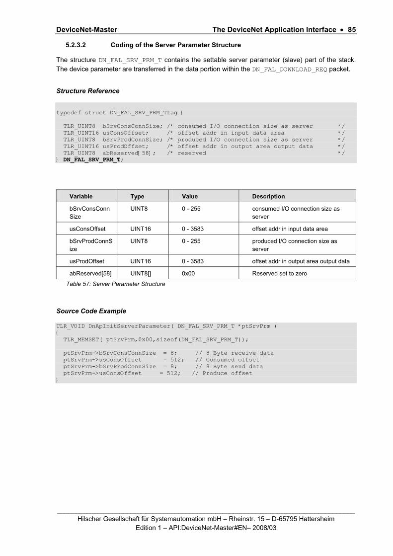
DeviceNet-Master The DeviceNet Application Interface • 85
_________________________________________________________________________________ Hilscher Gesellschaft für Systemautomation mbH – Rheinstr. 15 – D-65795 Hattersheim
Edition 1 – API:DeviceNet-Master#EN– 2008/03
5.2.3.2 Coding of the Server Parameter Structure
The structure DN_FAL_SRV_PRM_T contains the settable server parameter (slave) part of the stack. The device parameter are transferred in the data portion within the DN_FAL_DOWNLOAD_REQ packet.
Structure Reference
typedef struct DN_FAL_SRV_PRM_Ttag { TLR_UINT8 bSrvConsConnSize; /* consumed I/O connection size as server */ TLR_UINT16 usConsOffset; /* offset addr in input data area */ TLR_UINT8 bSrvProdConnSize; /* produced I/O connection size as server */ TLR_UINT16 usProdOffset; /* offset addr in output area output data */ TLR_UINT8 abReserved[58]; /* reserved */ } DN_FAL_SRV_PRM_T;
Variable Type Value Description
bSrvConsConnSize
UINT8 0 - 255 consumed I/O connection size as server
usConsOffset UINT16 0 - 3583 offset addr in input data area
bSrvProdConnSize
UINT8 0 - 255 produced I/O connection size as server
usProdOffset UINT16 0 - 3583 offset addr in output area output data
abReserved[58] UINT8[] 0x00 Reserved set to zero
Table 57: Server Parameter Structure
Source Code Example
TLR_VOID DnApInitServerParameter( DN_FAL_SRV_PRM_T *ptSrvPrm ) { TLR_MEMSET( ptSrvPrm,0x00,sizeof(DN_FAL_SRV_PRM_T)); ptSrvPrm->bSrvConsConnSize = 8; // 8 Byte receive data ptSrvPrm->usConsOffset = 512; // Consumed offset ptSrvPrm->bSrvProdConnSize = 8; // 8 Byte send data ptSrvPrm->usConsOffset = 512; // Produce offset }
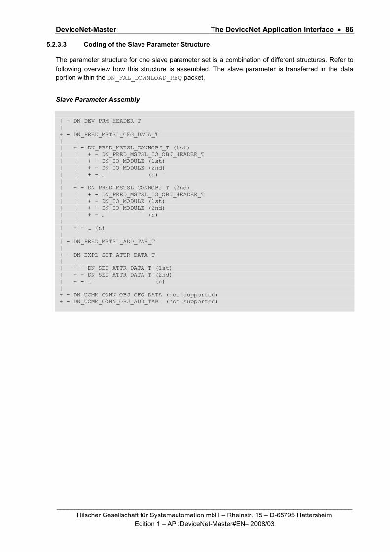
DeviceNet-Master The DeviceNet Application Interface • 86
_________________________________________________________________________________ Hilscher Gesellschaft für Systemautomation mbH – Rheinstr. 15 – D-65795 Hattersheim
Edition 1 – API:DeviceNet-Master#EN– 2008/03
5.2.3.3 Coding of the Slave Parameter Structure
The parameter structure for one slave parameter set is a combination of different structures. Refer to following overview how this structure is assembled. The slave parameter is transferred in the data portion within the DN_FAL_DOWNLOAD_REQ packet.
Slave Parameter Assembly
| - DN_DEV_PRM_HEADER_T | + - DN_PRED_MSTSL_CFG_DATA_T | | | + - DN_PRED_MSTSL_CONNOBJ_T (1st) | | + - DN_PRED_MSTSL_IO_OBJ_HEADER_T | | + - DN_IO_MODULE (1st) | | + - DN_IO_MODULE (2nd) | | + - … (n) | | | + - DN_PRED_MSTSL_CONNOBJ_T (2nd) | | + - DN_PRED_MSTSL_IO_OBJ_HEADER_T | | + - DN_IO_MODULE (1st) | | + - DN_IO_MODULE (2nd) | | + - … (n) | | | + - … (n) | | - DN_PRED_MSTSL_ADD_TAB_T | + - DN_EXPL_SET_ATTR_DATA_T | | | + - DN_SET_ATTR_DATA_T (1st) | + - DN_SET_ATTR_DATA_T (2nd) | + - … (n) | + - DN_UCMM_CONN_OBJ_CFG_DATA (not supported) + - DN_UCMM_CONN_OBJ_ADD_TAB (not supported)

DeviceNet-Master The DeviceNet Application Interface • 87
_________________________________________________________________________________ Hilscher Gesellschaft für Systemautomation mbH – Rheinstr. 15 – D-65795 Hattersheim
Edition 1 – API:DeviceNet-Master#EN– 2008/03
Header Structure Variable name Type Explanation
usDevParaLen word Length of whole data set inclusive the length ( 2 bytes) of the size indicator
bDvFlag byte Bit field, to activate the parameter data set and to indicate which kind of connections are supported, enable disable device keying
bUcmmGroup byte If device supported Dynamic Connections(UCMM) the connection group must specified here
usRecFragTimer word Timer value for in multiples of millisecond: - slave device times out and DeviceNet-Master tries the reconnection - maximum timeout duration in fragmentation protocol between two fragments.
usVendorID word Identification of vendor, managed by ODVA
usDeviceType word Indication of general type of product. List is available in DeviceNet spec
usProductCode word Identification of particular product
bMajorRevision byte Major revision of device
bMinorRevision byte Minor revision of device
DN_DEV_PRM_HEADER
bOctetString 2 byte Reserved bytes
usPredMstSlCfg DataLen
word Length of the following predefined master slave connection field inclusive the length ( 2 bytes) of the size indicator
DN_PRED_MSTSL_CFG_DATA _T
DN_PRED_MSTSL_ CONNOBJ_T
structure Predefined connections which shall be established to this device see corresponding HEADER file for structure
usAddTabLen word Length of the following additional process data offset table data inclusive the length ( 2 bytes) of the size indicator
bInputCount byte Number of input offset addresses in the offset table
bOutputCount byte Number of output offset addresses in the offset table
DN_PRED_MSTSL_ADD_TAB_T
ausIOOffsets word array
Offset address table for I/O data in the dual-port memory I/O area
usAttrDataLen word Length of the following set attribute data field inclusive the length ( 2 bytes) of the size indicator
DN_EXPL_SET_ATTR _DATA_T
DN_SET_ATTR_ DATA_T
structure Attributes which shall be changed via explicit messaging before doing I/O messaging see corresponding HEADER file for structure
DN_UCMM_CONN_OBJ_CFG_ DATA_T
usCfgDataLen word Length of the UCMM connection field inclusive the length ( 2 bytes) of the size indicator. Structure currently not supported. So length must be set to 2.
DN_UCMM_CONN_OBJ_ADD_TAB_T
usAddTabLen word Length of the following additional process data offset table data inclusive the length ( 2 bytes) of the size indicator. Structure currently not supported, so the length value

DeviceNet-Master The DeviceNet Application Interface • 88
_________________________________________________________________________________ Hilscher Gesellschaft für Systemautomation mbH – Rheinstr. 15 – D-65795 Hattersheim
Edition 1 – API:DeviceNet-Master#EN– 2008/03
must be set to 4 fixed.
bInputCount byte Number of input offset addresses in the offset table
bOutputCount byte Number of output offset addresses in the offset table
ausIOOffsets word array
Offset address table for I/O data in the dual-port memory I/O area. Not supported
Table 58: Slave Parameter Structure
The main length indicator usDevParaLen fixes the length of the whole data block including the length of the size indicator itself. The length can be calculated with the formula:
Length Calculation of Slave Parameter
usDevParaLen = 2 // size indicator itself + 14 // header bytes + usPredMstSlCfgDataLen // Predefined MstSl Config data + usAddTabLen // Address table length + usAttDataLen // ExplSetAttrData length + 2 // usCfgDataLen fixed + 4 // usAddTabLen fixed …
This variable is followed by a special bit field called bDvFlag, declaring the parameter data set either as active or inactive. Only if the ‘ACTIVE’ bit is set the DeviceNet-Master will actually activate the network access for this device.
bDevFlag
D7 D6 D5 D4 D3 D2 D1 D0
ACTIVE RES KEY_ REV
KEY_ PCODE
KEY_ DTYPE
KEY_ VENDOR RES UCMM_SUPP
Table 59: bDevFlag
The bit UCMM_SUPP indicates if the device supports the dynamic establishment of explicit messaging connections. Depending on this bit value the DeviceNet-Master will try to establish the explicit connection via unconnected services twice (1 second duration time between each try) before it will start to try it via predefined master slave connection services. Setting this bit for a slave device which does not support UCMM has the disadvantage that at least 2 seconds are lost until the devices connection can be established. The bits ‘KEY_XXX’ are enabling or disabling the electronic keying of a device. If enabled, the master checks the corresponding value usVendorID, usDevice-Type, usProductCode, bMajorRevision and bMinorRevision from the device data set with the physical present values in the devices Identity Object during its initialization. If one of these values differs, the connection to the device is denied because of safety reasons. The bit ‘ACTIVE’ activates or inactivates the data set. If the DeviceNet-Masteris in mode OPERATE and the bit is cleared then the device is not handled and remains in unconnected state for the specific device.

DeviceNet-Master The DeviceNet Application Interface • 89
_________________________________________________________________________________ Hilscher Gesellschaft für Systemautomation mbH – Rheinstr. 15 – D-65795 Hattersheim
Edition 1 – API:DeviceNet-Master#EN– 2008/03
The bUcmmGroup defines the message group across which messages associated with this connection are to be exchanged if the device is UCMM capable. The following values are defined:
#define DN_GROUP_1 0
#define DN_GROUP_2 1
#define DN_GROUP_3 3
Remember that the device itself selects the message group later across which the connection shall take place when the connection will be established. If the device cannot satisfy the intended bUcmmGroup selection, then it rejects the request and returns an error response. The value usRecFragTimer defines the "wait for acknowledgement" timer value which supervises after each transferred explicit request message the incoming corresponding response message. Furthermore the timer value defines the duration timer value between 2 requests that is used by the DeviceNet-Masterto retry the establishment of the devices connection after the connection was lost. The value range goes from 1 to 65535. The DN_PRED_MSTSL_CFG_DATA_T structure informs the DeviceNet-Masterabout the I/O connection that shall be established to the device and about the amount of produced or consumed I/O bytes that is transferred. The explicit message channel is established to each device anyway and must not be configured. So if it is wished the only the explicit message channel shall be established by the DeviceNet-Master, then the DN_PRED_MSTSL_CFG_DATA_T structure must be left empty. That means the parameter usPredMstSlCfgDataLen must be set to the value 2.
Header Structure variable name type explanation
bConnectionType byte type of connection that shall be established
bWatchdogTimeout action
byte behavior of the device if watchdog timeout expires through this connection
usProdInhibitTime word minimum delay between new data production in multiples of 1ms
usExpPacketRate word watchdog timer value of this connection
bNumOfIOModules byte number of following defined process data modules
DN_PRED_MSTSL_CONNOBJ
DN_IO_MODULE_T structure process data module definition
... for multiple connections
... ...
bConnectionType byte type of connection that shall be established
bWatchdogTimeout action
byte behavior of the device if watchdog timeout expires through this connection
usProdInhibitTime word minimum delay between new data production in multiples of 1ms
usExpPacketRate word watchdog timer value of this connection
bNumOfIOModules byte number of following defined process data modules
DN_PRED_MSTSL_CONNOBJ
DN_IO_MODULE_T structure process data module definition
Table 60: Additional Header Structures

DeviceNet-Master The DeviceNet Application Interface • 90
_________________________________________________________________________________ Hilscher Gesellschaft für Systemautomation mbH – Rheinstr. 15 – D-65795 Hattersheim
Edition 1 – API:DeviceNet-Master#EN– 2008/03
It is possible to configure multiple I/O connections to a device, like the structure above shows, but this is not usual to have in DeviceNet. So one connection to a device is usual.
See the structures DN_PRED_MSTSL_CONNOBJ_T
DN_PRED_MSTSL_IO_OBJ_HEADER_T
DN_I_O_MODULE_T
in the header file.
The bConnectionType defines which type of I/O connection shall be established to this device. The following values are defined:
#define DN_TYPE_CYCLIC 0x08
#define DN_TYPE_CHG_OF_STATE 0x04
#define DN_TYPE_BIT_STROBED 0x02
#define DN_TYPE_POLLED 0x01
#define DN_TYPE_CHG_OF_STATE_ACK 0x10
#define DN_TYPE_CYLIC_ACK 0x20
The bWatchdogTimeoutAction defines the behavior if the watchdog timer of the I/O connection expires. The following values are defined and their functionality is closer described in the DeviceNet specification.
#define DN_TRANSMISSION_TO_TIMEOUT 0x00
#define DN_AUTO_DELETE 0x01
#define DN_AUTO_RESET 0x02
The usProdInhibitTime, one for each connection, configures the minimum delay time between new data production in multiples of a millisecond. The timer is reloaded each time new data production through the established connection occurs. While the timer is running the DeviceNet-Master suppresses new data production until the timer has expired. This method prevents that the device is overloaded with to fast incoming requests. The value 0 defines no inhibit time and data production can and will be done as fast as possible. If in polled mode for example a usProdInhibitTime of 1000 (decimal) is configured, then the poll request message to the device will be sent every second. The usExpPacketRate, one for each connection, is always transferred to the device before starting and doing the I/O transfer . The value is used by the device later to reload its 'Transmission Trigger' and 'Watchdog Timer'. The 'Transmission Trigger Timer' is used in a 'cyclic' I/O connection to control the time when the data shall be produced. Expiration of this timer then is an indication that the associated connection must transmit the corresponding I/O message. In 'change of state' connections the timer is used to avoid the watchdog timeout in this connection, when a production has not occured since the timer was activated or reloaded. Remark: the usProdInhibitTime is verified against the usExpPacketRate. If the usExpPacketRate value is unequal zero, but less than the usProdInhibitTime value, then an error is returned.
The bNumOfIOModules value defines how many so called Input / Output modules are defined in the directly following structure DN_IO_MODULE_T. The table DN_IO_MODULE_T defines which type of process data and in sum how many data shall be transferred through this connection. The structure DN_IO_MODULE_T itself has a size of two bytes per defined I or O module. The first byte of each structure contains the bDataType of the I/O module. Following values are defined:
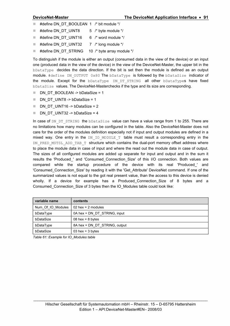
DeviceNet-Master The DeviceNet Application Interface • 91
_________________________________________________________________________________ Hilscher Gesellschaft für Systemautomation mbH – Rheinstr. 15 – D-65795 Hattersheim
Edition 1 – API:DeviceNet-Master#EN– 2008/03
#define DN_DT_BOOLEAN 1 /* bit module */
#define DN_DT_UINT8 5 /* byte module */
#define DN_DT_UINT16 6 /* word module */
#define DN_DT_UINT32 7 /* long module */
#define DN_DT_STRING 10 /* byte array module */
To distinguish if the module is either an output (consumed data in the view of the device) or an input one (produced data in the view of the device) in the view of the DeviceNet-Master, the upper bit in the bDataType decides the data direction. If the bit is set then the module is defined as an output module. #define DN_OUTPUT 0x80 The bDataType is followed by the bDataSize indicator of the module. Except for the bDataType DN_DT_STRING all other bDataTypes have fixed bDataSize values. The DeviceNet-Masterchecks if the type and its size are corresponding.
DN_DT_BOOLEAN -> bDataSize = 1
DN_DT_UINT8 -> bDataSize = 1
DN_DT_UINT16 -> bDataSize = 2
DN_DT_UINT32 -> bDataSize = 4
In case of DN_DT_STRING the bDataSize value can have a value range from 1 to 255. There are no limitations how many modules can be configured in the table. Also the DeviceNet-Master does not care for the order of the modules definition especially not if input and output modules are defined in a mixed way. One entry in the DN_IO_MODULE_T table must result a corresponding entry in the DN_PRED_MSTSL_ADD_TAB_T structure which contains the dual-port memory offset address where to place the module data in case of input and where the read out the module data in case of output. The sizes of all configured modules are added up separate for input and output and in the sum it results the 'Produced_' and 'Consumed_Connection_Size' of this I/O connection. Both values are compared while the startup procedure of the device with its real 'Produced_' and 'Consumed_Connection_Size' by reading it with the 'Get_Attribute' DeviceNet command. If one of the summarized values is not equal to the got real present value, than the access to this device is denied wholly. If a device for example has a Produced_Connection_Size of 8 bytes and a Consumed_Connection_Size of 3 bytes then the IO_Modules table could look like:
variable name contents
Num_Of_IO_Modules 02 hex = 2 modules
bDataType 0A hex = DN_DT_STRING, input
bDataSize 08 hex = 8 bytes
bDataType 8A hex = DN_DT_STRING, output
bDataSize 03 hex = 3 bytes
Table 61: Example for IO_Modules table
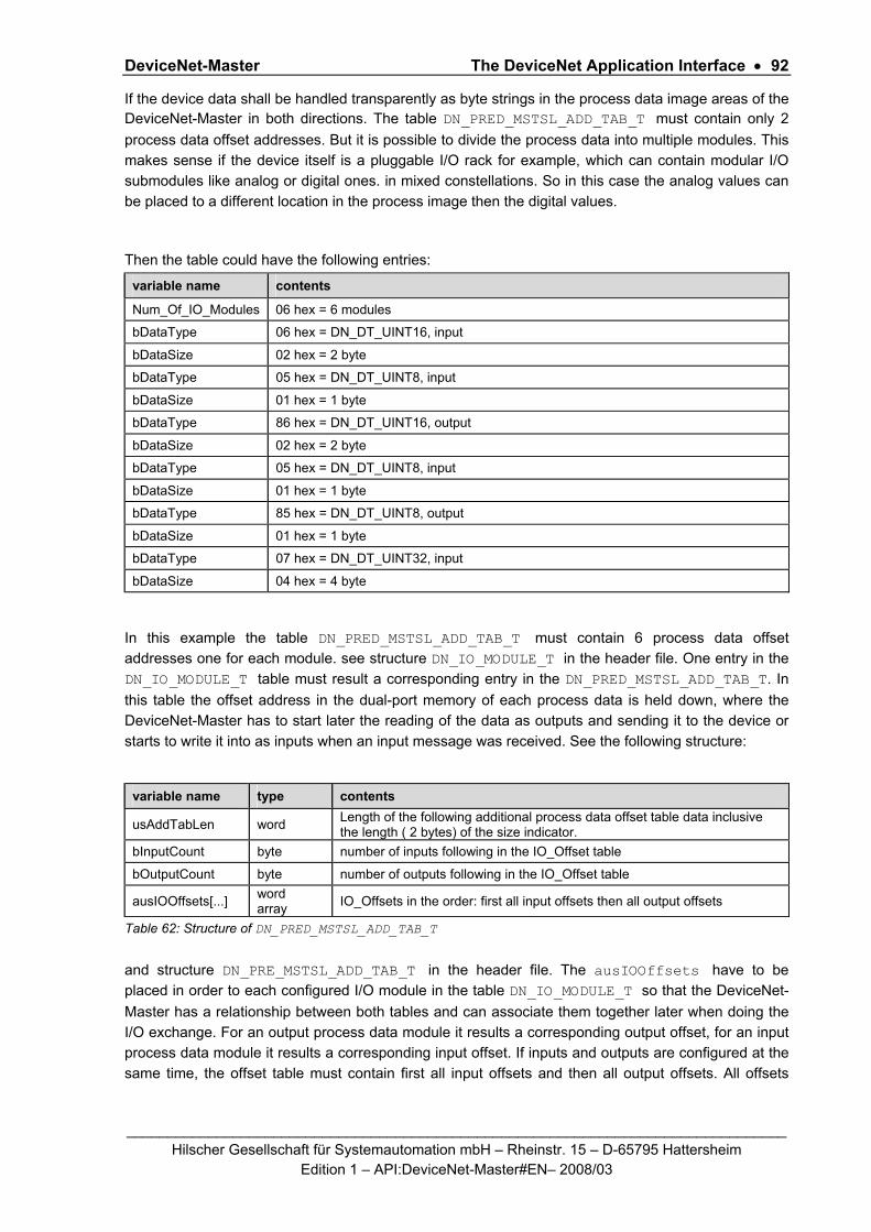
DeviceNet-Master The DeviceNet Application Interface • 92
_________________________________________________________________________________ Hilscher Gesellschaft für Systemautomation mbH – Rheinstr. 15 – D-65795 Hattersheim
Edition 1 – API:DeviceNet-Master#EN– 2008/03
If the device data shall be handled transparently as byte strings in the process data image areas of the DeviceNet-Master in both directions. The table DN_PRED_MSTSL_ADD_TAB_T must contain only 2 process data offset addresses. But it is possible to divide the process data into multiple modules. This makes sense if the device itself is a pluggable I/O rack for example, which can contain modular I/O submodules like analog or digital ones. in mixed constellations. So in this case the analog values can be placed to a different location in the process image then the digital values.
Then the table could have the following entries:
variable name contents
Num_Of_IO_Modules 06 hex = 6 modules
bDataType 06 hex = DN_DT_UINT16, input
bDataSize 02 hex = 2 byte
bDataType 05 hex = DN_DT_UINT8, input
bDataSize 01 hex = 1 byte
bDataType 86 hex = DN_DT_UINT16, output
bDataSize 02 hex = 2 byte
bDataType 05 hex = DN_DT_UINT8, input
bDataSize 01 hex = 1 byte
bDataType 85 hex = DN_DT_UINT8, output
bDataSize 01 hex = 1 byte
bDataType 07 hex = DN_DT_UINT32, input
bDataSize 04 hex = 4 byte
In this example the table DN_PRED_MSTSL_ADD_TAB_T must contain 6 process data offset addresses one for each module. see structure DN_IO_MODULE_T in the header file. One entry in the DN_IO_MODULE_T table must result a corresponding entry in the DN_PRED_MSTSL_ADD_TAB_T. In this table the offset address in the dual-port memory of each process data is held down, where the DeviceNet-Master has to start later the reading of the data as outputs and sending it to the device or starts to write it into as inputs when an input message was received. See the following structure:
variable name type contents
usAddTabLen word Length of the following additional process data offset table data inclusive the length ( 2 bytes) of the size indicator.
bInputCount byte number of inputs following in the IO_Offset table
bOutputCount byte number of outputs following in the IO_Offset table
ausIOOffsets[...] word array IO_Offsets in the order: first all input offsets then all output offsets
Table 62: Structure of DN_PRED_MSTSL_ADD_TAB_T
and structure DN_PRE_MSTSL_ADD_TAB_T in the header file. The ausIOOffsets have to be placed in order to each configured I/O module in the table DN_IO_MODULE_T so that the DeviceNet-Master has a relationship between both tables and can associate them together later when doing the I/O exchange. For an output process data module it results a corresponding output offset, for an input process data module it results a corresponding input offset. If inputs and outputs are configured at the same time, the offset table must contain first all input offsets and then all output offsets. All offsets

DeviceNet-Master The DeviceNet Application Interface • 93
_________________________________________________________________________________ Hilscher Gesellschaft für Systemautomation mbH – Rheinstr. 15 – D-65795 Hattersheim
Edition 1 – API:DeviceNet-Master#EN– 2008/03
must be configured as byte offsets, except an offset for a single bit DN_DT_BOOLEAN process data. There an offset must be set up like the following figure illustrates:
D15 D14 D13 D12 D11 D10 D9 D8 D7 D6 D5 D4 D3 D2 D1 D0
Bit offset Byte offset
byte offset in the dual port memory (0 - 3583 decimal)
Corresponding bit offset in the byte 0 -7dec
Table 63: Structure of IO_Offsets
To complete the last example above, here is a related DN_PRE_MSTSL_ADD_TAB_T example: The 4 input modules data shall be located at byte 4-5dec,0,20dec,3000-3003dec. The word output module shall be located at byte 10dec-11dec and the byte output module at byte 2dec.
variable name contents
usAddTabLen 0010 hex = 16 bytes in length, inclusive the length indicator
bInputCount 04 hex = 4 input offsets following
bOutputCount 02 hex = 2 output offsets following
ausIOOffsets[0] 0004 hex = word input module, byte 4-5
ausIOOffsets[1] 0000 hex = byte input module, byte 0
ausIOOffsets[2] 0014 hex = byte input module, byte 20
ausIOOffsets[3] 0BB8 hex = long input module, byte 3000-3003
ausIOOffsets[4] 000A hex = word output module, byte 10-11
ausIOOffsets[5] 0002 hex = byte output module, byte 2
Table 64: Structure of DN_PRE_MSTSL_ADD_TAB_T
The DN_PRED_MSTSL_CFG_DATA_T structure represents the parameter data containing structure of each device. The DeviceNet-Master takes all configured attributes with their configured values from this table and compares the contents during the device's startup with the physically present attribute values of the device. If the compared pair of values are different the DeviceNet-Master sends the configured new value to the device with the DeviceNet 'Set_Attribute' write command. DNM devices store such parameter data normally into an electronic erasable PROM, which has limitations in its write procedures. This mechanism 'write if different' guarantees that the parameter data is not transferred useless and the PROM would not be programmed in vain to hold its life expectancy high. If a write command would be denied by the device, the DeviceNet-Master does not stop the parameterization and finalizes it by taking the next configured entry. A denied write request will only be logged in the internal device specific diagnostic structure, which can be read out with the DNM_Device_Diag message.

DeviceNet-Master The DeviceNet Application Interface • 94
_________________________________________________________________________________ Hilscher Gesellschaft für Systemautomation mbH – Rheinstr. 15 – D-65795 Hattersheim
Edition 1 – API:DeviceNet-Master#EN– 2008/03
Header Structure variable name type explanation
usClass ID word class which shall be addressed, 0- 65535
usInstanceID word instance in this class which shall be addressed 0-65535
bAttributeID byte attribute which shall be addressed, 0- 255
bDataCnt byte length of following data 0-255
DN_SET_ATTR_DATA_T
abData[...] octet string data field
... if more attributes shall be changed
... ...
usClass ID word class which shall be addressed, 0- 65535
usInstanceID word instance in this class which shall be addressed 0-65535
bAttributeID byte attribute which shall be addressed, 0- 255
bDataCnt byte length of following data 0-255
DN_SET_ATTR_DATA_T
abData[...] octet string data field
Table 65: Structure of DN_SET_ATTR_DATA_T
See structure DN_SET_ATTR_DATA_T in the header file. There are no limitations how many attributes can be configured in the table. Each attribute is addressed in DeviceNet and in each entry by its usClassID, usInstanceID location and its bAttributeID. The number of data bytes which shall be compared and written if unequal is fixed in the variable bDataCnt. If no attributes shall be changed while the device's network startup procedure, then the leading length indicator usAttrDataLen must contain the value 2 which represents the byte length of the indicator itself then.
If for example the attribute 1 = 'MAC_ID' in DeviceNet object class 3 instance 1 shall be changed to the value 10 when the device is started up later, the DN_EXPL_SET_ATTR_DATA_T entry should have the following data entries:
Variable name Contents
usAttrDataLen 0009 hex
usClassID 0003 hex
usInstanceID 0001 hex
bAttributeID 01 hex
bDataCnt 01 hex
abData[0] 10 hex
Table 66: Example for DN_EXPL_SET_ATTR_DATA_T
The next table DN_UCMM_CONN_OBJ_CFG_DATA_T is used for further extension of the firmware of the DeviceNet-Master. Because of this, only the size of the structure usCfgDataLen is defined at the moment in a device data set. The value in there must be set up to 2 to be compatible in future with incoming firmware versions. Based on the same reason the corresponding

DeviceNet-Master The DeviceNet Application Interface • 95
_________________________________________________________________________________ Hilscher Gesellschaft für Systemautomation mbH – Rheinstr. 15 – D-65795 Hattersheim
Edition 1 – API:DeviceNet-Master#EN– 2008/03
DN_UCMM_CONN_OBJ_ADD_TAB_T and its length must be reserved also in the device data set. usAddTabLen must be set up to a length of 4 fixed.
Example of Message Device Parameter Data Sets Hexadecimal
TLR_RESULT InitGetSlaveParameter( TLR_UINT32 ulSlvNum, TLR_UINT8** ppabSlvPrm, TLR_UINT32 *pulPrmLen ) { // - No Input and output process data, explicit only connection STATIC TLR_UINT8 abSlvSet1{} = { 1E,00,80,00,e8,03,00,00,00,00,00,00,00,00,00,00, //DN_DEV_PRM_HEADER_T 02,00, //DN_PRED_MSTSL_CFG_DATA_T, empty, only length itself = 2 04,00,00,00, //DN_PRED_MSTSL_ADD_TAB_T no input and output offset 02,00, //DN_SET_ATTIBUTE_DATA_T, empty table, only length itself = 2 02,00, //DN_UCMM_CONN_OBJ_CFG_DATA_T, empty table, only length itself = 2 04,00,00,00 //DN_UCMM_CONN_OBJ_ADD_TAB_T no offsets } // - Polling connection, 7 byte input , 8 bytes output STATIC TLR_UINT8 abSlvSet2{} = { 2D,00,80,00,40,06,00,00,00,00,00,00,00,00,00,00, //DN_DEV_PRM_HEADER_T 0D,00,01,00,0A,00,00,00,02,0A,07,8A,08, //DN_PRED_MSTSL_CFG_DATA_T 08,00,01,01,00,00,00,00, //DN_PRED_MSTSL_ADD_TAB_T offset = 0 02,00, //DN_SET_ATTIBUTE_DATA_T, empty table, only length itself = 2 02,00, //DN_UCMM_CONN_OBJ_CFG_DATA_T, empty table, only length itself = 2 04,00,00,00 //DN_UCMM_CONN_OBJ_ADD_TAB_T no offsets } // - Polling connection UCMM group 3 capable device, 7 byte input 8 bytes output TLR_UINT8 abSlvSet3{} = { 2D,00,81,03,40,06,00,00,00,00,00,00,00,00,00,00, //DN_DEV_PRM_HEADER_T 0D,00,01,00,14,00,1E,00,02,0A,07,8A,08, //DN_PRED_MSTSL_CFG_DATA_T 08,00,01,01,00,00,00,00, //DN_PRED_MSTSL_ADD_TAB_T offset = 0 02,00, //DN_SET_ATTIBUTE_DATA, empty table, only length itself = 2 02,00, //DN_UCMM_CONN_OBJ_CFG_DATA_T, empty table, only length itself = 2 04,00,00,00 //DN_UCMM_CONN_OBJ_ADD_TAB_T no offsets } // - Bit-Strobe connection, 8 bytes input TLR_UINT8 abSlvSet3{} = { 29,00,80,00,40,06,00,00,00,00,00,00,00,00,00,00, //DN_DEV_PRM_HEADE_T R 0B,00,02,00,14,00,1E,00,01,0A,08, //DN_PRED_MSTSL_CFG_DATA_T 06,00,01,00,00, //DN_PRED_MSTSL_ADD_TAB_T input offset = 0 02,00, //DN_SET_ATTIBUTE_DATA, empty table, only length itself = 2 02,00, //DN_UCMM_CONN_OBJ_CFG_DATA_T, empty table, only length itself = 2 04,00,00,00 //DN_UCMM_CONN_OBJ_ADD_TAB_T no offsets } switch(ulSlvNum ) { case 1: {*ppabSlvPrm = &abSlvSet1[0]; *pulPrmLen = sizeof(abSlvSet1);} break; case 2: {*ppabSlvPrm = &abSlvSet2[0]; *pulPrmLen = sizeof(abSlvSet2);} break; case 3: {*ppabSlvPrm = &abSlvSet3[0]; *pulPrmLen = sizeof(abSlvSet3);} break; case 4: {*ppabSlvPrm = &abSlvSet4[0]; *pulPrmLen = sizeof(abSlvSet4);} break; default: {*ppabSlvPrm =NULL; *pulPrmLen = 0;} break; } }

DeviceNet-Master The DeviceNet Application Interface • 96
_________________________________________________________________________________ Hilscher Gesellschaft für Systemautomation mbH – Rheinstr. 15 – D-65795 Hattersheim
Edition 1 – API:DeviceNet-Master#EN– 2008/03
5.2.3.4 Coding of the Bus Parameter Structure
The structure DN_FAL_BUS_PRM_T contains the bus parameters of the stack which are available to be set. The bus parameters are transferred in the data portion within the DN_FAL_DOWNLOAD_REQ packet. After sending the bus parameter the configuration process is finished. It is not possible to send further slave, server or device parameters.
Structure Reference
typedef struct DN_FAL_BUS_PRM_Ttag { TLR_UINT32 ulSystemFlags; /* System flags */ TLR_UINT32 ulWdgTime; /* Watchdog */ TLR_UINT32 ulOwnMacId; /* Device MAC ID */ TLR_UINT32 ulBaudrate; /* Device Baudrate */ TLR_UINT32 ulConfigFlags; /* Configuration flags */ TLR_UINT32 ulEnableFlags; /* Enable Flags */ TLR_UINT8 abReserved[40]; /* Reserved */ } DN_FAL_BUS_PRM_T;
Variable Type Value Description
ulSystemFlags UINT32 0x00000000 - 0x00000001 System Flags
ulWdgTime UINT32 0x00000000 - 0x0000FFFF Watchdog Time
ulOwnMacId UINT32 0 .. 63 Own MAC ID
ulBaudrate UINT32 1 .. 3 Baud rate
1 = DN_FAL_BAUDRATE_500 2 = DN_FAL_BAUDRATE_250 3 = DN_FAL_BAUDRATE_125
ulConfigFlags UINT32 0x00000000 - 0x00000003 Configuration Flags
ulEnableFlags UINT32 0x00000000 Reserved set to zero
abReserved[..] UINT8[] 0x00 Reserved set to zero
Table 67: Bus Parameter Structure
Flag Flag Name
DN_FAL_MSK_BUS_PRM_SYS_FLAG
Description
0x00000001 _CTRL_RELEASE If this bit is set the communication starts when application is ready if not set it starts automatically to communicate
0xFFFFFFFE _FLAG_RESERVED Reserved Flags always set to zero
Table 68: System Flags

DeviceNet-Master The DeviceNet Application Interface • 97
_________________________________________________________________________________ Hilscher Gesellschaft für Systemautomation mbH – Rheinstr. 15 – D-65795 Hattersheim
Edition 1 – API:DeviceNet-Master#EN– 2008/03
Flag Flag Name
DN_FAL_MSK_BUS_PRM_CFG_FLAG
Description
0x00000001 _AUTOCLEAR The flag defines the system behavior if one as active classified device has been disconnected. If AutoClear mode is active then the DeviceNet-Master stops the communication to all other devices too, else it tries to restart the missed device and keeps running.
0x00000002 _INTEL_MOTOROLA Reserved Flag set to zero
0xFFFFFFFC _FLAG_RESERVED Reserved Flags always set to zero
Table 69: Configuration Flags
Source Code Example
TLR_VOID InitBusParameter( DN_FAL_BUS_PRM_T *ptBusPrm ) { TLR_MEMSET( ptBusPrm,0x00,sizeof(DN_FAL_BUS_PRM_T)); ptBusPrm->ulOwnMacId = 1; // Own MAC ID ptBusPrm->usProductCode = DN_FAL_BAUDRATE_125; // Baudrate }

DeviceNet-Master The DeviceNet Application Interface • 98
_________________________________________________________________________________ Hilscher Gesellschaft für Systemautomation mbH – Rheinstr. 15 – D-65795 Hattersheim
Edition 1 – API:DeviceNet-Master#EN– 2008/03
5.2.4 DEVNET_FAL_CMD_GET_ATT_REQ/CNF – Get Attribute Request
The command DEVNET_FAL_GET_ATT_REQ is used by a user application to request the value of an attribute from a device/slave according the DeviceNet Object model. For a brief description of the available objects see section 1.4.2 “Object Modeling”.
An explanation of how this command is used is as follows.
Packet Structure Reference
#define DN_FAL_SDU_GETSET_ATT_MAX_DATA (240) typedef struct DN_FAL_SDU_GETSET_ATT_REQ_Ttag { TLR_UINT8 bDeviceAddr; TLR_UINT8 abReserved[3]; TLR_UINT16 usClass; TLR_UINT16 usInstance; TLR_UINT16 usAttribute; TLR_UINT16 usReserved; TLR_UINT8 abAttData[DN_FAL_SDU_GETSET_ATT_MAX_DATA]; }DN_FAL_SDU_GETSET_ATT_REQ_T; typedef struct DN_FAL_PACKET_GET_ATT_REQ_Ttag { TLR_PACKET_HEADER_T tHead; DN_FAL_SDU_GETSET_ATT_REQ_T tData; } DN_FAL_PACKET_GET_ATT_REQ_T;

DeviceNet-Master The DeviceNet Application Interface • 99
_________________________________________________________________________________ Hilscher Gesellschaft für Systemautomation mbH – Rheinstr. 15 – D-65795 Hattersheim
Edition 1 – API:DeviceNet-Master#EN– 2008/03
Packet Description
structure DN_FAL_PACKET_GET_ATT_REQ_T
Type: Request
Area Variable Type Value / Range Description
Head structure TLR_PACKET_HEADER_T
ulDest UINT32 Destination Queue-Handle
ulSrc UINT32 Source Queue-Handle of AP-Task Process Queue
ulDestId UINT32 0 Destination End Point Identifier, specifying the final receiver of the packet within the Destination Process. Set to 0 for the Initialization Packet
ulSrcId UINT32 0 ... 232-1 Source End Point Identifier, specifying the origin of the packet inside the Source Process
ulLen UINT32 12 DN_FAL_GETSET_ATT_REQ_SIZE
ulId UINT32 0 ... 232-1 Packet Identification as unique number generated by the Source Process of the Packet
ulSta UINT32 0 Set to zero
ulCmd UINT32 0x380A DEVNET_FAL_CMD_GET_ATT_REQ - Command
ulExt UINT32 0 Extension not in use, set to zero for compatibility reasons
ulRout UINT32 0 Routing, set to zero
Data structure DN_FAL_SDU_GETSET_ATT_REQ_T
bDeviceAddr UINT8 0-63 Device address,
MAC-ID of device to be addressed
abReserved[3] UINT8[] 0 Reserved zero
usClass UINT16 0 ... 216-1 Class ID
usInstance UINT16 0 ... 216-1 Instance ID
usAttribute UINT16 0 ... 216-1 Attribute ID
usReserved UINT16 0 Set to zero
abAttData[0 .. 239] UINT8[] 0 Attribute Data not used in request
Table 70: DEVNET_FAL_CMD_GET_ATT_REQ - Get Attribute Request

DeviceNet-Master The DeviceNet Application Interface • 100
_________________________________________________________________________________ Hilscher Gesellschaft für Systemautomation mbH – Rheinstr. 15 – D-65795 Hattersheim
Edition 1 – API:DeviceNet-Master#EN– 2008/03
Source Code Example
TLR_RESULT DnUser_GetAttReq( DN_USER_RSC_T FAR* ptRsc ) { TLR_RESULT eRslt = TLR_S_OK; DN_FAL_PACKET_GET_ATT_REQ_T *ptGetAttReq = NULL; eRslt = TLR_POOL_PACKET_GET(ptRsc->tLoc.hPool,&ptGetAttReq); if( eRslt == TLR_S_OK ) { //Zero packet memory TLR_MEMSET(&ptGetAttReq->tHead,0x00,sizeof(ptGetAttReq->tHead)); TLR_MEMSET(&ptGetAttReq->tData,0x00,DN_FAL_GETSET_ATT_REQ_SIZE); //Init packet header TLR_QUE_LINK_SET_PACKET_SRC(ptGetAttReq,ptRsc->tLoc.tQueSrcApp); ptGetAttReq->tHead.ulCmd = DEVNET_FAL_CMD_GET_ATT_REQ; ptGetAttReq->tHead.ulLen = DN_FAL_GETSET_ATT_REQ_SIZE; //Init packet data ptSetModeReq->tData.bDeviceAddr = 2; //DeviceAddress ptSetModeReq->tData.usClass = 1; //IdentityObject ptSetModeReq->tData.usInstance = 1; //Instance ptSetModeReq->tData.usAttribute = 7; //ProductName //Send packet eRslt = TLR_QUE_SENDPACKET_FIFO(ptRsc->tLoc.tDstQue,ptSetModeReq,TLR_FINITE); if( eRslt != TLR_S_OK ) { TLR_POOL_PACKET_RELEASE(ptRsc->tLoc.hPool, ptInitReq); } } return eRslt; }
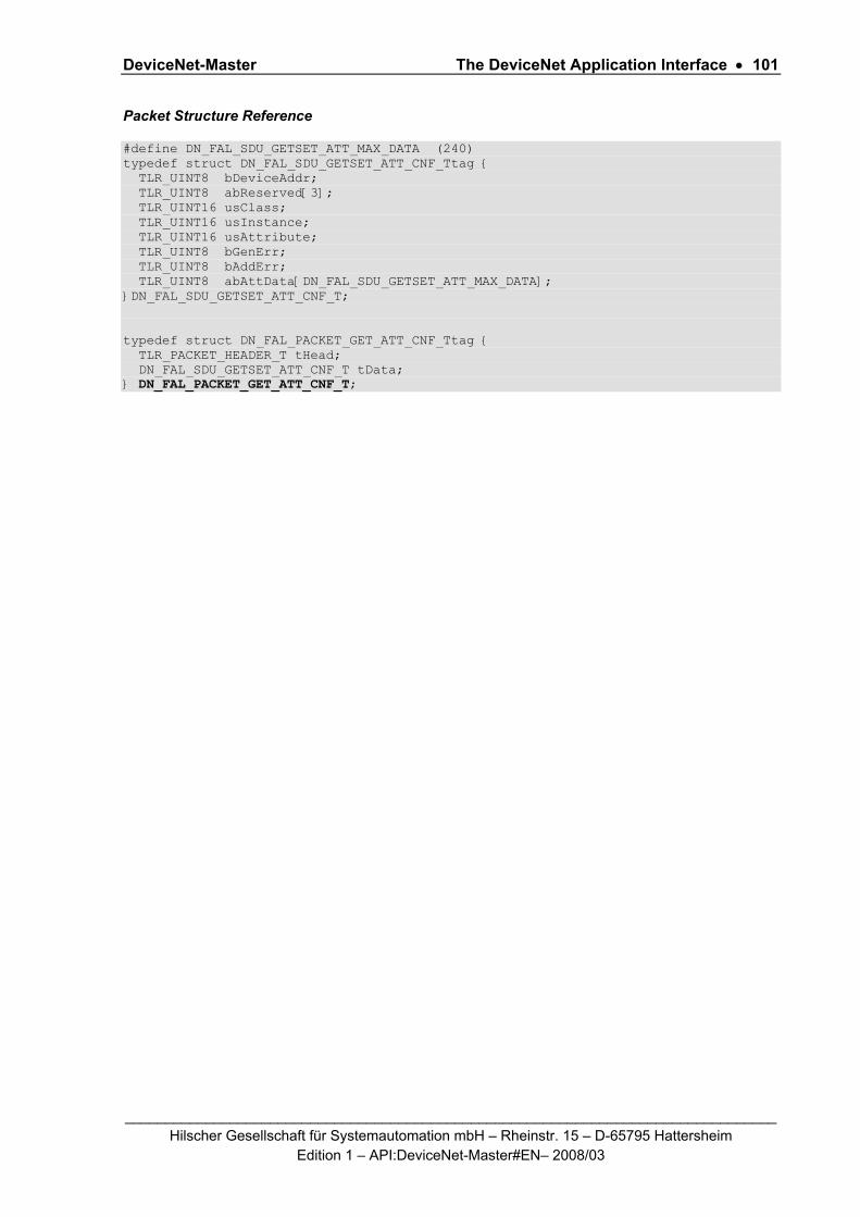
DeviceNet-Master The DeviceNet Application Interface • 101
_________________________________________________________________________________ Hilscher Gesellschaft für Systemautomation mbH – Rheinstr. 15 – D-65795 Hattersheim
Edition 1 – API:DeviceNet-Master#EN– 2008/03
Packet Structure Reference
#define DN_FAL_SDU_GETSET_ATT_MAX_DATA (240) typedef struct DN_FAL_SDU_GETSET_ATT_CNF_Ttag { TLR_UINT8 bDeviceAddr; TLR_UINT8 abReserved[3]; TLR_UINT16 usClass; TLR_UINT16 usInstance; TLR_UINT16 usAttribute; TLR_UINT8 bGenErr; TLR_UINT8 bAddErr; TLR_UINT8 abAttData[DN_FAL_SDU_GETSET_ATT_MAX_DATA]; }DN_FAL_SDU_GETSET_ATT_CNF_T; typedef struct DN_FAL_PACKET_GET_ATT_CNF_Ttag { TLR_PACKET_HEADER_T tHead; DN_FAL_SDU_GETSET_ATT_CNF_T tData; } DN_FAL_PACKET_GET_ATT_CNF_T;

DeviceNet-Master The DeviceNet Application Interface • 102
_________________________________________________________________________________ Hilscher Gesellschaft für Systemautomation mbH – Rheinstr. 15 – D-65795 Hattersheim
Edition 1 – API:DeviceNet-Master#EN– 2008/03
Packet Description
structure DN_FAL_PACKET_GET_ATT_CNF _T
Type: Request
Area Variable Type Value / Range Description
Head structure TLR_PACKET_HEADER_T
ulDest UINT32 Destination Queue-Handle
ulSrc UINT32 Source Queue-Handle of AP-Task Process Queue
ulDestId UINT32 0 Destination End Point Identifier, specifying the final receiver of the packet within the Destination Process. Set to 0 for the Initialization Packet
ulSrcId UINT32 0 ... 232-1 Source End Point Identifier, specifying the origin of the packet inside the Source Process
ulLen UINT32 12 + n DN_FAL_GETSET_ATT_CNF_SIZE + number of attibute data received
ulId UINT32 0 ... 232-1 Packet Identification as unique number generated by the Source Process of the Packet
ulSta UINT32 0 set to zero
ulCmd UINT32 0x380B DEVNET_FAL_CMD_GET_ATT_CNF - Command
ulExt UINT32 0 Extension not in use
ulRout UINT32 x Routing
Data structure DN_FAL_SDU_GETSET_ATT_CNF_T
bDeviceAddr UINT8 0-63 MAC-ID of the device that was addresses
abReserved[3] UINT8 0 Reserved zero
usClass UINT16 0 ... 216-1 Class ID, returned
usInstance UINT16 0 ... 216-1 Instance ID, returned
usAttribute UINT16 0 ... 216-1 Attribute ID, returned
bGenErr UINT8 0 .. 255 See Table below
bAddErr UINT8 0 .. 255 See Table below
abAttData[0 .. 239] UINT8 array
xxx Attribute Data received
Table 71: DEVNET_FAL_CMD_GET_ATT_CNF - Confirmation of Get Attribute Request

DeviceNet-Master The DeviceNet Application Interface • 103
_________________________________________________________________________________ Hilscher Gesellschaft für Systemautomation mbH – Rheinstr. 15 – D-65795 Hattersheim
Edition 1 – API:DeviceNet-Master#EN– 2008/03
Packet Status/Error
Status/Error_Code Description
TLR_S_OK (0x00000000)
Status ok
TLR_E_DEVNET_FAL_MAC_ID_OUT_OF_RANGE (0xC0470101)
MAC ID out of range
TLR_E_DEVNET_FAL_CON_LE (0xC0470233)
Invalid request packet length
TLR_E_DEVNET_FAL_CON_SE (0xC0470239)
Sequence error in response
TLR_E_DEVNET_FAL_CON_OC (0xC0470240)
Another get or set command still active
TLR_E_DEVNET_FAL_CON_NA (0xC0470211)
No response from the network device, timeout
TLR_E_DEVNET_FAL_CON_MDA (0xC0470215)
Too much data received in confirmation
TLR_E_DEVNET_FAL_CON_ERR_RES (0xC0470294)
Error Response from device, for more details see Table below bGenErr/bAddErr
Table 72: DEVNET_FAL_CMD_GET_ATT_CNF – Packet Status/Error
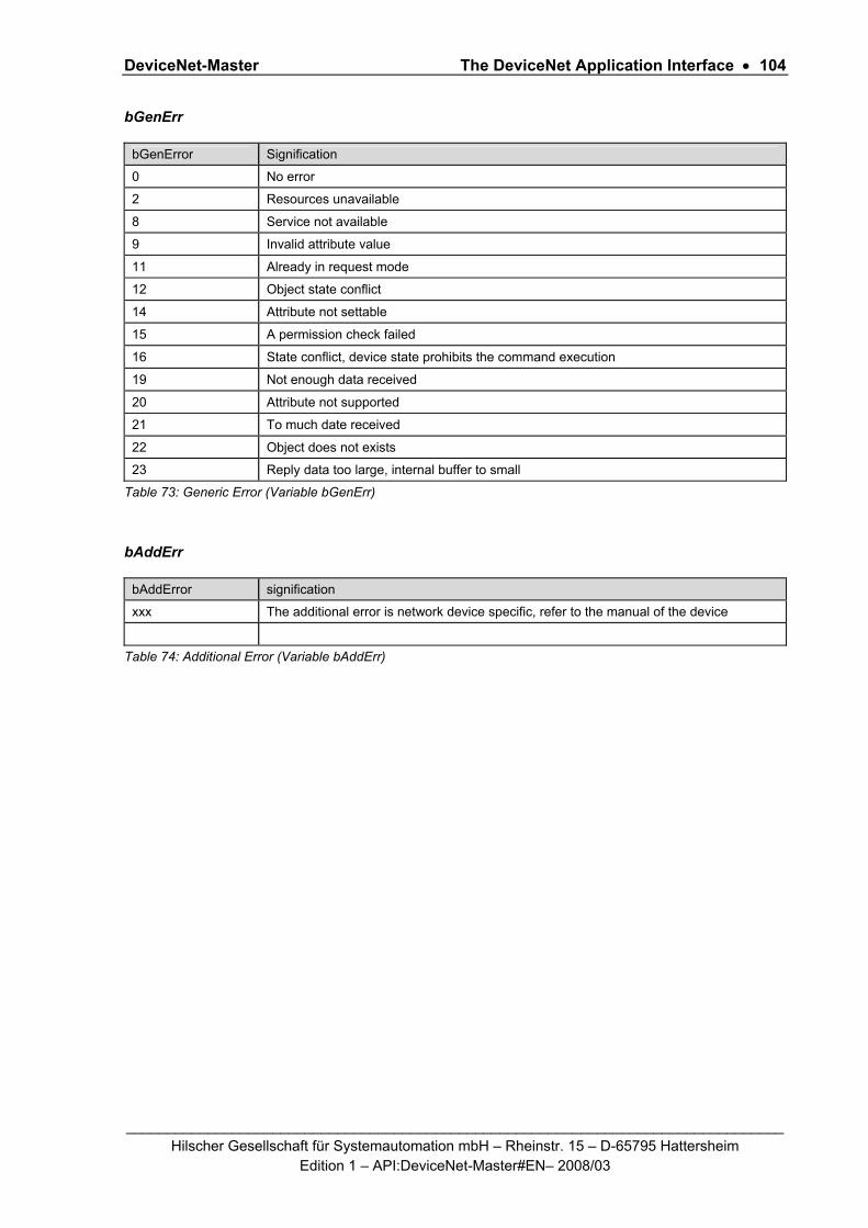
DeviceNet-Master The DeviceNet Application Interface • 104
_________________________________________________________________________________ Hilscher Gesellschaft für Systemautomation mbH – Rheinstr. 15 – D-65795 Hattersheim
Edition 1 – API:DeviceNet-Master#EN– 2008/03
bGenErr
bGenError Signification
0 No error
2 Resources unavailable
8 Service not available
9 Invalid attribute value
11 Already in request mode
12 Object state conflict
14 Attribute not settable
15 A permission check failed
16 State conflict, device state prohibits the command execution
19 Not enough data received
20 Attribute not supported
21 To much date received
22 Object does not exists
23 Reply data too large, internal buffer to small
Table 73: Generic Error (Variable bGenErr)
bAddErr
bAddError signification
xxx The additional error is network device specific, refer to the manual of the device
Table 74: Additional Error (Variable bAddErr)

DeviceNet-Master The DeviceNet Application Interface • 105
_________________________________________________________________________________ Hilscher Gesellschaft für Systemautomation mbH – Rheinstr. 15 – D-65795 Hattersheim
Edition 1 – API:DeviceNet-Master#EN– 2008/03
5.2.5 DEVNET_FAL_CMD_SET_ATT_REQ/CNF – Set Attribute Request
The command DEVNET_FAL_SET_ATT_REQ is used by a user application to set an attribute within a device/slave according the DeviceNet Object model. For a brief description of the available objects see section 1.4.2 “Object Modeling”.
An explanation of how this command is used is as follows.
Packet Structure Reference
#define DN_FAL_SDU_GETSET_ATT_MAX_DATA (240) typedef struct DN_FAL_SDU_GETSET_ATT_REQ_Ttag { TLR_UINT8 bDeviceAddr; TLR_UINT8 abReserved[3]; TLR_UINT16 usClass; TLR_UINT16 usInstance; TLR_UINT16 usAttribute; TLR_UINT16 usReserved; TLR_UINT8 abAttData[DN_FAL_SDU_GETSET_ATT_MAX_DATA]; }DN_FAL_SDU_GETSET_ATT_REQ_T; typedef struct DN_FAL_PACKET_SET_ATT_REQ_Ttag { TLR_PACKET_HEADER_T tHead; DN_FAL_SDU_GETSET_ATT_REQ_T tData; } DN_FAL_PACKET_SET_ATT_REQ_T;
Packet Description
structure DN_FAL_PACKET_SET_ATT_REQ_T
Type: Request
Area Variable Type Value / Range Description
Head structure TLR_PACKET_HEADER_T
ulDest UINT32 Destination Queue-Handle
ulSrc UINT32 Source Queue-Handle of AP-Task Process Queue
ulDestId UINT32 0 Destination End Point Identifier, specifying the final receiver of the packet within the Destination Process. Set to 0 for the Initialization Packet
ulSrcId UINT32 0 ... 232-1 Source End Point Identifier, specifying the origin of the packet inside the Source Process
ulLen UINT32 12 + n sizeof(DN_FAL_SDU_GETSET_ATT_REQ_T) + number of attribute data to set
ulId UINT32 0 ... 232-1 Packet Identification as unique number generated by the Source Process of the Packet
ulSta UINT32 0 Set to zero
ulCmd UINT32 0x380C DEVNET_FAL_CMD_SET_ATT_REQ - Command
ulExt UINT32 0 Extension not in use, set to zero for compatibility reasons
ulRout UINT32 0 Routing, set to zero
Data structure DN_FAL_SDU_GETSET_ATT_REQ_T

DeviceNet-Master The DeviceNet Application Interface • 106
_________________________________________________________________________________ Hilscher Gesellschaft für Systemautomation mbH – Rheinstr. 15 – D-65795 Hattersheim
Edition 1 – API:DeviceNet-Master#EN– 2008/03
structure DN_FAL_PACKET_SET_ATT_REQ_T
Type: Request
Area Variable Type Value / Range Description
bDeviceAddr UINT8 0-63 Device address,
MAC-ID of device to be addresses
abReserved[3] UINT8 0 Reserved zero
usClass UINT16 0 ... 216-1 Class ID
usInstance UINT16 0 ... 216-1 Instance ID
usAttribute UINT16 0 ... 216-1 Attribute ID
usReserved UINT16 0 Set to zero
abAttData[0 .. 239 ] UINT8 array
x Attribute Data to be set
Table 75: DEVNET_FAL_CMD_SET_ATT_REQ - Set Attribute Request

DeviceNet-Master The DeviceNet Application Interface • 107
_________________________________________________________________________________ Hilscher Gesellschaft für Systemautomation mbH – Rheinstr. 15 – D-65795 Hattersheim
Edition 1 – API:DeviceNet-Master#EN– 2008/03
Packet Structure Reference
#define DN_FAL_SDU_GETSET_ATT_MAX_DATA (240) typedef struct DN_FAL_SDU_GETSET_ATT_CNF_Ttag { TLR_UINT8 bDeviceAddr; TLR_UINT8 abReserved[3]; TLR_UINT16 usClass; TLR_UINT16 usInstance; TLR_UINT16 usAttribute; TLR_UINT8 bGenErr; TLR_UINT8 bAddErr; TLR_UINT8 abAttData[DN_FAL_SDU_GETSET_ATT_MAX_DATA]; }DN_FAL_SDU_GETSET_ATT_CNF_T; typedef struct DN_FAL_PACKET_SET_ATT_CNF_Ttag { TLR_PACKET_HEADER_T tHead; DN_FAL_SDU_GETSET_ATT_CNF_T tData; } DN_FAL_PACKET_SET_ATT_CNF_T;

DeviceNet-Master The DeviceNet Application Interface • 108
_________________________________________________________________________________ Hilscher Gesellschaft für Systemautomation mbH – Rheinstr. 15 – D-65795 Hattersheim
Edition 1 – API:DeviceNet-Master#EN– 2008/03
Packet Description
structure DN_FAL_PACKET_SET_ATT_CNF_T
Type: Request
Area Variable Type Value / Range Description
Head structure TLR_PACKET_HEADER_T
ulDest UINT32 Destination Queue-Handle
ulSrc UINT32 Source Queue-Handle of AP-Task Process Queue
ulDestId UINT32 0 Destination End Point Identifier, specifying the final receiver of the packet within the Destination Process. Set to 0 for the Initialization Packet
ulSrcId UINT32 0 ... 232-1 Source End Point Identifier, specifying the origin of the packet inside the Source Process
ulLen UINT32 12 DN_FAL_GETSET_ATT_CNF_SIZE
ulId UINT32 0 ... 232-1 Packet Identification as unique number generated by the Source Process of the Packet
ulSta UINT32 x see Table Packet Status/Error below
ulCmd UINT32 0x380D DEVNET_FAL_CMD_SET_ATT_CNF - Command
ulExt UINT32 0 Extension not in use
ulRout UINT32 x Routing, don’t touch
Data structure DN_FAL_SDU_GETSET_ATT_REQ_T
bDeviceAddr UINT8 0-63 Device address,
MAC-ID of device that was addresses
abReserved[3] UINT8 0 Reserved zero
usClass UINT16 0 ... 216-1 Class ID, returned
usInstance UINT16 0 ... 216-1 Instance ID, returned
usAttribute UINT16 0 ... 216-1 Attribute ID, returned
bGenErr UINT8 0 .. 255 See Table below
bAddErr UINT8 0 .. 255 See Table below
abAttData[0 .. 239 ] UINT8 array
0 Unused in confirmation packet
Table 76: DEVNET_FAL_CMD_SET_ATT_REQ - Confirmation of Set Attribute Request

DeviceNet-Master The DeviceNet Application Interface • 109
_________________________________________________________________________________ Hilscher Gesellschaft für Systemautomation mbH – Rheinstr. 15 – D-65795 Hattersheim
Edition 1 – API:DeviceNet-Master#EN– 2008/03
Packet Status/Error
Definition / (Value) Description
TLR_S_OK (0x00000000)
Status ok
TLR_E_DEVNET_FAL_MAC_ID_OUT_OF_RANGE (0xC0470101)
MAC ID out of range
TLR_E_DEVNET_FAL_CON_LE (0xC0470233)
Invalid request packet length
TLR_E_DEVNET_FAL_CON_OC (0xC0470240)
Another get or set command still active
Table 77: DEVNET_FAL_CMD_SET_ATT_ CNF_T – Packet Status/Error
DeviceNet-Master The DeviceNet Application Interface • 110
_________________________________________________________________________________ Hilscher Gesellschaft für Systemautomation mbH – Rheinstr. 15 – D-65795 Hattersheim
Edition 1 – API:DeviceNet-Master#EN– 2008/03
5.2.6 DEVNET_FAL_CMD_ACYC_BTS_REQ/CNF – Acyclic Bit-Strobing
This packet has been designed to accomplish acyclic bit-strobing. This is a special method to synchronize the host application and the DeviceNet master device and to plan synchronous actions of master and (single or multiple) slaves.
Bit strobing is initiated by the DeviceNet-Master by sending a special I/O message, i.e. the bit strobe command message. This bit strobe command message is a multi-cast message allowing multiple slaves to react synchronously to the same message as they should receive it at the same time. Within a DeviceNet Slave, the bit strobe command and its associated response are received and transmitted by one single connection object.
The reaction to the bit strobe command is application-specific and known at the DeviceNet-Master.
In an 8-byte telegram each of 64 available bits represents one of the 64 possible participants of the DeviceNet network as the number of MAC IDs is limited to 64. This telegram contents is also denominated as the “master scan list”. For the structure of the master scan list, the following rules apply:
The lowest MAC ID, i.e. 0, is assigned to the low-order bit in the lowest-order byte of the telegram.
The highest MAC ID, i.e. 0, is assigned to the high-order bit in the highest -order byte of the telegram.
These rules result in the assignment table which is represented by Table 26 below.
Each of these slaves receiving the bit strobing command message has the possibility to decide between the following alternatives on reception of a bit strobe command from the master:
Ignore the bit strobe command, for instance a polled device would behave in this way.
Consume both the bit strobe command and its data
Consume the bit strobe command only, but ignore its data
The applied telegrams are unconfirmed. Instead of a confirmation a time-out mechanism has been established in the following manner: After a previously determined time (the time-out value), the DeviceNet-Master will collect and evaluate the responses of the DeviceNet Slaves, and provide the results to the application.
In order to perform bit-strobing practically, the following information needs to be provided: The time-out value to apply
The time-out value just defines the duration how long the DeviceNet-Master has to wait
A list of the slave devices in the DeviceNet network to be included to bit-strobing. This is done by providing the bit mask of a width of 64-bits.
ulDeviceList / Bit field for slaves configured for bit-strobing (device list)
This variable is a field of 8 bytes and contains the information which slave devices are currently configured for bit-strobing. The following table shows, which bit is related to which slave station address:

DeviceNet-Master The DeviceNet Application Interface • 111
_________________________________________________________________________________ Hilscher Gesellschaft für Systemautomation mbH – Rheinstr. 15 – D-65795 Hattersheim
Edition 1 – API:DeviceNet-Master#EN– 2008/03
Bit
Byte
D7 D6 D5 D4 D3 D2 D1 D0
0 7 6 5 4 3 2 1 0
1 15 14 13 12 11 10 9 8
2 23 22 21 20 19 18 17 16
…
7 63 62 61 60 59 58 57 56
Table 78: Assignment Table for Bits in Master Scan List and associated MAC IDs of DeviceNet Slaves
The interpretation is as follows:
If the ulDeviceList bit of the corresponding slave is logically
'1', the slave is configured for bit-strobing.
'0', the slave is not configured for bit-strobing, and should not participate in bit-strobing.
The results provided by the confirmation packet contain
A status list indicating which devices reacted to the bit strobing. This status list is structured similarly to the device list. If the ulStatusList bit of the corresponding slave is logically
'1', the slave is configured for bit-strobing. '0', the slave is not configured for bit-strobing, and will not participate in bit-strobing.
An additional data array tData[64] containing information about each device within the DeviceNet network.
Note: If a DEVNET_FAL_CMD_ACYC_BTS_REQ packet has already been sent earlier and is still not completely processed, the status of the confirmation packet will be set to TLR_E_DEVNET_FAL_BTS_IN_PROGRESS indicating that processing of the lifelist is still in progress.
Packet Structure Reference
typedef struct DN_FAL_BTS_REQ_Ttag { TLR_UINT32 ulTimeOut; TLR_UINT64 ulDeviceList; // List of devices to be strobed }DN_FAL_BTS_REQ_T; typedef struct DN_FAL_PACKET_BTS_REQ_Ttag { TLR_PACKET_HEADER_T tHead; DN_FAL_BTS_REQ_T tData; } DN_FAL_PACKET_BTS_REQ_T;

DeviceNet-Master The DeviceNet Application Interface • 112
_________________________________________________________________________________ Hilscher Gesellschaft für Systemautomation mbH – Rheinstr. 15 – D-65795 Hattersheim
Edition 1 – API:DeviceNet-Master#EN– 2008/03
Packet Description
structure DN_FAL_PACKET_BTS_REQ_T
Type: Request
Area Variable Type Value / Range Description
structure TLR_PACKET_HEADER_T
ulDest UINT32 Destination Queue-Handle
ulSrc UINT32 Source Queue-Handle
ulDestId UINT32 Destination End Point Identifier, specifying the final receiver of the packet within the Destination Process. Set to 0 for the Initialization Packet
ulSrcId UINT32 Source End Point Identifier, specifying the origin of the packet inside the Source Process
ulLen UINT32 12 Packet Data Length in bytes
ulId UINT32 0 ... 232-1 Packet Identification as unique number generated by the Source Process of the Packet
ulSta UINT32 See Table 80: DEVNET_FAL_CMD_ACYC_BTS_REQ - Packet Status/Error
ulCmd UINT32 0x3812 DEVNET_FAL_CMD_ACYC_BTS_REQ - Command
ulExt UINT32 0 Extension not in use, set to zero for compatibility reasons
tHead
ulRout UINT32 x Routing, do not touch
tData structure DN_FAL_BTS_REQ_T
ulTimeOut UINT32 Time-out value specified in multiples of timer ticks
ulDeviceList UINT64 List of devices to be strobed
(1 bit per device according to assignment as explained in Table 78 above)
Table 79: DEVNET_FAL_CMD_ACYC_BTS_REQ – Acyclic Bit-Strobing
Packet Status/Error
Definition / (Value) Description
TLR_S_OK (0x00000000)
Status ok
Table 80: DEVNET_FAL_CMD_ACYC_BTS_REQ - Packet Status/Error

DeviceNet-Master The DeviceNet Application Interface • 113
_________________________________________________________________________________ Hilscher Gesellschaft für Systemautomation mbH – Rheinstr. 15 – D-65795 Hattersheim
Edition 1 – API:DeviceNet-Master#EN– 2008/03
Packet Structure Reference
typedef struct DM_FAL_BTS_MSG_Tag { TLR_UINT8 bDeviceAddr; TLR_UINT8 bLength:4; TLR_UINT8 bStatus:4; TLR_UINT8 abData[8]; }DM_FAL_BTS_MSG_T; typedef struct DN_FAL_BTS_CNF_Ttag { TLR_UINT64 ulStatusList; DM_FAL_BTS_MSG_T tData[64]; }DN_FAL_BTS_CNF_T; typedef struct DN_FAL_PACKET_BTS_CNF_Ttag { TLR_PACKET_HEADER_T tHead; DN_FAL_BTS_CNF_T tData; }DN_FAL_PACKET_BTS_CNF_T;
Packet Description
structure DN_FAL_PACKET_BTS_CNF_T
Type: Confirmation
Area Variable Type Value / Range Description
structure TLR_PACKET_HEADER_T
ulDest UINT32 Destination Queue-Handle
ulSrc UINT32 Source Queue-Handle
ulDestId UINT32 Destination End Point Identifier, specifying the final receiver of the packet within the Destination Process. Set to 0 for the Initialization Packet
ulSrcId UINT32 Source End Point Identifier, specifying the origin of the packet inside the Source Process
ulLen UINT32 648 Packet Data Length in bytes
ulId UINT32 0 ... 232-1 Packet Identification as unique number generated by the Source Process of the Packet
ulSta UINT32 See Table 82: DEVNET_FAL_CMD_ACYC_BTS_CNF - Packet Status/Error
ulCmd UINT32 0x3813 DEVNET_FAL_CMD_ACYC_BTS_CNF - Command
ulExt UINT32 0 Extension not in use, set to zero for compatibility reasons
tHead
ulRout UINT32 x Routing, do not touch
tData structure DN_FAL_BTS_CNF_T
ulStatusList UINT64 Status list
tData[64] DN_FAL_BTS_MSG_T
Data
Table 81: DEVNET_FAL_CMD_ACYC_BTS_CNF – Confirmation of Acyclic Bit-Strobing

DeviceNet-Master The DeviceNet Application Interface • 114
_________________________________________________________________________________ Hilscher Gesellschaft für Systemautomation mbH – Rheinstr. 15 – D-65795 Hattersheim
Edition 1 – API:DeviceNet-Master#EN– 2008/03
Packet Status/Error
Definition / (Value) Description
TLR_S_OK (0x00000000)
Status ok
TLR_E_DEVNET_FAL_BTS_IN_PROGRESS (0xC0470296L)
Bit-strobing in progress
Table 82: DEVNET_FAL_CMD_ACYC_BTS_CNF - Packet Status/Error
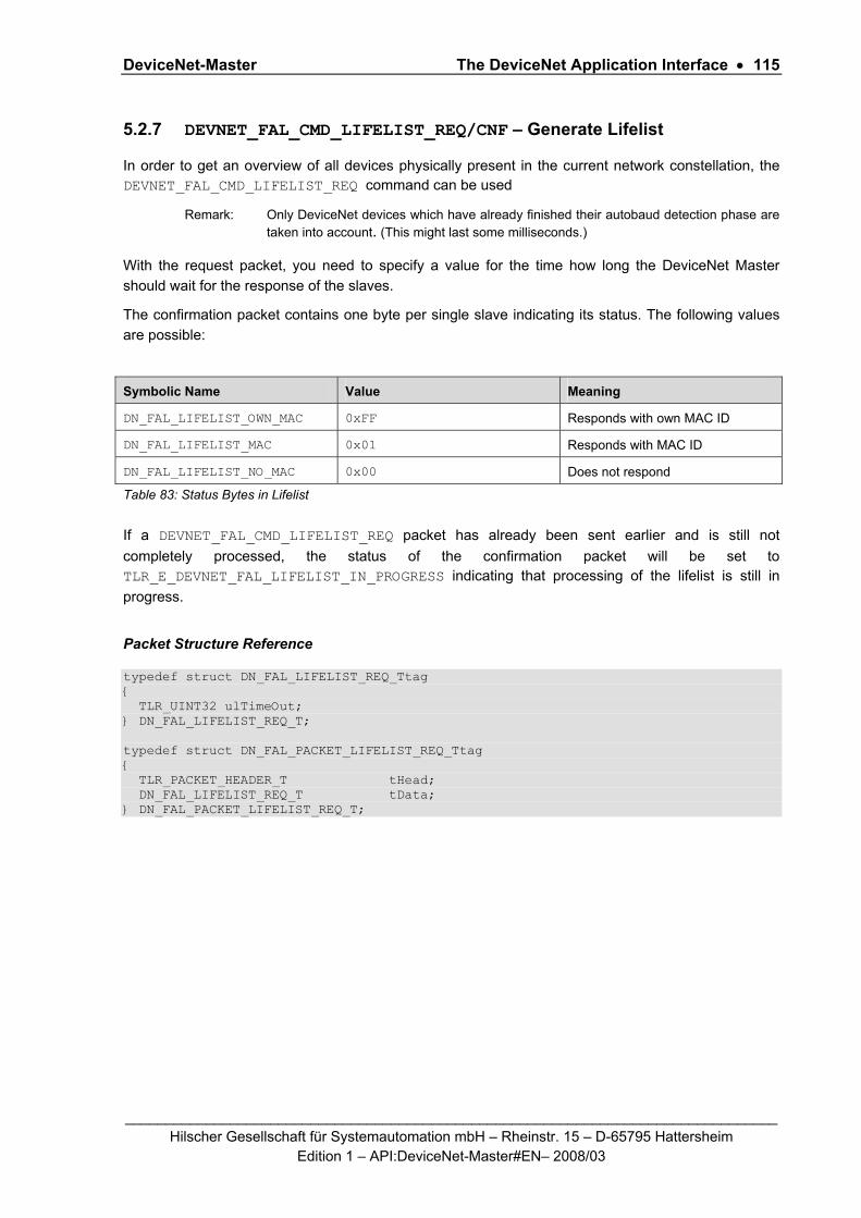
DeviceNet-Master The DeviceNet Application Interface • 115
_________________________________________________________________________________ Hilscher Gesellschaft für Systemautomation mbH – Rheinstr. 15 – D-65795 Hattersheim
Edition 1 – API:DeviceNet-Master#EN– 2008/03
5.2.7 DEVNET_FAL_CMD_LIFELIST_REQ/CNF – Generate Lifelist
In order to get an overview of all devices physically present in the current network constellation, the DEVNET_FAL_CMD_LIFELIST_REQ command can be used
Remark: Only DeviceNet devices which have already finished their autobaud detection phase are taken into account. (This might last some milliseconds.)
With the request packet, you need to specify a value for the time how long the DeviceNet Master should wait for the response of the slaves.
The confirmation packet contains one byte per single slave indicating its status. The following values are possible:
Symbolic Name Value Meaning
DN_FAL_LIFELIST_OWN_MAC 0xFF Responds with own MAC ID
DN_FAL_LIFELIST_MAC 0x01 Responds with MAC ID
DN_FAL_LIFELIST_NO_MAC 0x00 Does not respond
Table 83: Status Bytes in Lifelist
If a DEVNET_FAL_CMD_LIFELIST_REQ packet has already been sent earlier and is still not completely processed, the status of the confirmation packet will be set to TLR_E_DEVNET_FAL_LIFELIST_IN_PROGRESS indicating that processing of the lifelist is still in progress.
Packet Structure Reference
typedef struct DN_FAL_LIFELIST_REQ_Ttag { TLR_UINT32 ulTimeOut; } DN_FAL_LIFELIST_REQ_T; typedef struct DN_FAL_PACKET_LIFELIST_REQ_Ttag { TLR_PACKET_HEADER_T tHead; DN_FAL_LIFELIST_REQ_T tData; } DN_FAL_PACKET_LIFELIST_REQ_T;

DeviceNet-Master The DeviceNet Application Interface • 116
_________________________________________________________________________________ Hilscher Gesellschaft für Systemautomation mbH – Rheinstr. 15 – D-65795 Hattersheim
Edition 1 – API:DeviceNet-Master#EN– 2008/03
Packet Description
structure DN_FAL_PACKET_LIFELIST_REQ_T
Type: Request
Area Variable Type Value / Range Description
structure TLR_PACKET_HEADER_T
ulDest UINT32 Destination Queue-Handle
ulSrc UINT32 Source Queue-Handle
ulDestId UINT32 Destination End Point Identifier, specifying the final receiver of the packet within the Destination Process. Set to 0 for the Initialization Packet
ulSrcId UINT32 Source End Point Identifier, specifying the origin of the packet inside the Source Process
ulLen UINT32 4 Packet Data Length in bytes
ulId UINT32 0 ... 232-1 Packet Identification as unique number generated by the Source Process of the Packet
ulSta UINT32 See Table 85: DEVNET_FAL_CMD_LIFELIST_REQ – Packet Status/Error
ulCmd UINT32 0x3814 DEVNET_FAL_CMD_LIFELIST_REQ - Command
ulExt UINT32 0 Extension not in use, set to zero for compatibility reasons
tHead
ulRout UINT32 x Routing, do not touch
tData structure DN_FAL_LIFELIST_REQ_T
ulTimeOut UINT32 Time-out value specified in multiples of timer ticks
Table 84: DEVNET_FAL_CMD_LIFELIST_REQ – Generate Lifelist
Packet Status/Error
Definition / (Value) Description
TLR_S_OK (0x00000000)
Status ok
Table 85: DEVNET_FAL_CMD_LIFELIST_REQ – Packet Status/Error

DeviceNet-Master The DeviceNet Application Interface • 117
_________________________________________________________________________________ Hilscher Gesellschaft für Systemautomation mbH – Rheinstr. 15 – D-65795 Hattersheim
Edition 1 – API:DeviceNet-Master#EN– 2008/03
Packet Structure Reference
typedef struct DN_FAL_LIFELIST_CNF_Ttag { TLR_UINT8 abDevices[64]; } DN_FAL_LIFELIST_CNF_T; typedef struct DN_FAL_PACKET_LIFELIST_CNF_Ttag { TLR_PACKET_HEADER_T tHead; DN_FAL_LIFELIST_CNF_T tData; } DN_FAL_PACKET_LIFELIST_CNF_T;
Packet Description
structure DN_FAL_PACKET_LIFELIST_CNF_T
Type: Confirmation
Area Variable Type Value / Range Description
structure TLR_PACKET_HEADER_T
ulDest UINT32 Destination Queue-Handle
ulSrc UINT32 Source Queue-Handle
ulDestId UINT32 Destination End Point Identifier, specifying the final receiver of the packet within the Destination Process. Set to 0 for the Initialization Packet
ulSrcId UINT32 Source End Point Identifier, specifying the origin of the packet inside the Source Process
ulLen UINT32 64 Packet Data Length in bytes
ulId UINT32 0 ... 232-1 Packet Identification as unique number generated by the Source Process of the Packet
ulSta UINT32 See Table 87: DEVNET_FAL_CMD_LIFELIST_CNF – Packet Status/Error
ulCmd UINT32 0x3815 DEVNET_FAL_CMD_LIFELIST_CNF - Command
ulExt UINT32 0 Extension not in use, set to zero for compatibility reasons
tHead
ulRout UINT32 x Routing, do not touch
tData structure DN_FAL_LIFELIST_CNF_T
abDevices[64] UINT8[] Lifelist
Table 86: DEVNET_FAL_CMD_LIFELIST_CNF – Confirmation of Generate Lifelist
Packet Status/Error
Definition / (Value) Description
TLR_S_OK (0x00000000)
Status ok
TLR_E_DEVNET_FAL_LIFELIST_IN_PROGRESS (0xC0470295L)
Lifelist in progress
Table 87: DEVNET_FAL_CMD_LIFELIST_CNF – Packet Status/Error

DeviceNet-Master The DeviceNet Application Interface • 118
_________________________________________________________________________________ Hilscher Gesellschaft für Systemautomation mbH – Rheinstr. 15 – D-65795 Hattersheim
Edition 1 – API:DeviceNet-Master#EN– 2008/03
5.2.8 DEVNET_FAL_CMD_UPLOAD_REQ/CNF –Parameter Upload
The command DEVNET_FAL_CMD_UPLOAD_REQ is used to upload a configuration (i.e. a complete set of parameters) from the DeviceNet stack to the application. The download is divided into so called areas like bus, device, slave or server parameter sets.
The same area definitions apply as in the context of the DEVNET_FAL_CMD_DOWNLOAD_REQ/CNF – Download DeviceNet Configuration command, see below in the description of the parameters.
The data delivered in the abData[1000] array of the confirmation packet is structured exactly as described in sections 5.2.3.1 to 5.2.3.4 of this document. Which section to apply depends on your choice of the usArea parameter.
Packet Structure Reference
typedef struct DN_FAL_SDU_UPLOAD_REQ_Ttag { TLR_UINT16 usArea; TLR_UINT16 usSubArea; } DN_FAL_SDU_UPLOAD_REQ_T; typedef struct DN_FAL_PACKET_UPLOAD_REQ_Ttag { TLR_PACKET_HEADER_T tHead; /* Packet header */ DN_FAL_SDU_UPLOAD_REQ_T tData; /* Packet data */ } DN_FAL_PACKET_UPLOAD_REQ_T;

DeviceNet-Master The DeviceNet Application Interface • 119
_________________________________________________________________________________ Hilscher Gesellschaft für Systemautomation mbH – Rheinstr. 15 – D-65795 Hattersheim
Edition 1 – API:DeviceNet-Master#EN– 2008/03
Packet Description
structure DN_FAL_PACKET_UPLOAD_REQ_T
Type: Request
Area Variable Type Value / Range Description
structure TLR_PACKET_HEADER_T
ulDest UINT32 Destination Queue-Handle
ulSrc UINT32 Source Queue-Handle
ulDestId UINT32 Destination End Point Identifier, specifying the final receiver of the packet within the Destination Process. Set to 0 for the Initialization Packet
ulSrcId UINT32 Source End Point Identifier, specifying the origin of the packet inside the Source Process
ulLen UINT32 4 Packet Data Length in bytes
ulId UINT32 0 ... 232-1 Packet Identification as unique number generated by the Source Process of the Packet
ulSta UINT32 See Table 89: DEVNET_FAL_CMD_UPLOAD_REQ - Packet Status/Error
ulCmd UINT32 0x3816 DEVNET_FAL_CMD_UPLOAD_REQ - Command
ulExt UINT32 0 Extension not in use, set to zero for compatibility reasons
tHead
ulRout UINT32 x Routing, do not touch
tData structure DN_FAL_SDU_UPLOAD_REQ_T
usArea UINT16 Area code of where the data is to be downloaded.
DN_FAL_DOWNLOAD_AREA_BUS_PARAMETER DN_FAL_DOWNLOAD_AREA_SLAVE_PARAMETER DN_FAL_DOWNLOAD_AREA_SERVER_PARAMETER DN_FAL_DOWNLOAD_AREA_DEVICE_PARAMETER
usSubArea UINT16 depends on usArea
…_AREA_BUS_PARAMETER 0 …_AREA_SLAVE_PARAMETER 0..63 ( Mac ID ) …_AREA_SERVER_PARAMETER 0 …_AREA_DEVICE_PARAMETER 0
Table 88: DEVNET_FAL_CMD_UPLOAD_REQ - Parameter Upload
Packet Status/Error
Definition / (Value) Description
TLR_S_OK (0x00000000)
Status ok
Table 89: DEVNET_FAL_CMD_UPLOAD_REQ - Packet Status/Error

DeviceNet-Master The DeviceNet Application Interface • 120
_________________________________________________________________________________ Hilscher Gesellschaft für Systemautomation mbH – Rheinstr. 15 – D-65795 Hattersheim
Edition 1 – API:DeviceNet-Master#EN– 2008/03
Packet Structure Reference
typedef struct DN_FAL_SDU_UPLOAD_CNF_Ttag { TLR_UINT16 usArea; TLR_UINT16 usSubArea; TLR_UINT8 abData[1000]; }DN_FAL_SDU_UPLOAD_CNF_T; #define DN_FAL_UPLOAD_CNF_SIZE sizeof(DN_FAL_SDU_UPLOAD_CNF_T) typedef struct DN_FAL_PACKET_UPLOAD_CNF_Ttag { TLR_PACKET_HEADER_T tHead; /* Packet header */ DN_FAL_SDU_UPLOAD_CNF_T tData; /* Packet data */ }DN_FAL_PACKET_UPLOAD_CNF_T;

DeviceNet-Master The DeviceNet Application Interface • 121
_________________________________________________________________________________ Hilscher Gesellschaft für Systemautomation mbH – Rheinstr. 15 – D-65795 Hattersheim
Edition 1 – API:DeviceNet-Master#EN– 2008/03
Packet Description
structure DN_FAL_PACKET_UPLOAD_CNF_T
Type: Confirmation
Area Variable Type Value / Range Description
structure TLR_PACKET_HEADER_T
ulDest UINT32 Destination Queue-Handle
ulSrc UINT32 Source Queue-Handle
ulDestId UINT32 Destination End Point Identifier, specifying the final receiver of the packet within the Destination Process. Set to 0 for the Initialization Packet
ulSrcId UINT32 Source End Point Identifier, specifying the origin of the packet inside the Source Process
ulLen UINT32 1004 Packet Data Length in bytes
ulId UINT32 0 ... 232-1 Packet Identification as unique number generated by the Source Process of the Packet
ulSta UINT32 See Table 91: DEVNET_FAL_CMD_UPLOAD_CNF - Packet Status/Error
ulCmd UINT32 0x3817 DEVNET_FAL_CMD_UPLOAD_CNF - Command
ulExt UINT32 0 Extension not in use, set to zero for compatibility reasons
tHead
ulRout UINT32 x Routing, do not touch
tData structure DN_FAL_SDU_UPLOAD_CNF_T
usArea UINT16 Area code of where the data is to be downloaded.
DN_FAL_DOWNLOAD_AREA_BUS_PARAMETER DN_FAL_DOWNLOAD_AREA_SLAVE_PARAMETER DN_FAL_DOWNLOAD_AREA_SERVER_PARAMETER DN_FAL_DOWNLOAD_AREA_DEVICE_PARAMETER
usSubArea UINT16 depends on usArea
…_AREA_BUS_PARAMETER 0 …_AREA_SLAVE_PARAMETER 0..63 ( Mac ID ) …_AREA_SERVER_PARAMETER 0 …_AREA_DEVICE_PARAMETER 0
abData[1000] UINT8[] Download data contents depending on usArea
Table 90: DEVNET_FAL_CMD_UPLOAD_CNF – Confirmation of Upload
Packet Status/Error
Definition / (Value) Description
TLR_S_OK (0x00000000)
Status ok
TLR_E_DEVNET_FAL_UPLOAD_INVALID_AREA_CODE
Invalid value in 'Area Code' of command.
Table 91: DEVNET_FAL_CMD_UPLOAD_CNF - Packet Status/Error

DeviceNet-Master The DeviceNet Application Interface • 122
_________________________________________________________________________________ Hilscher Gesellschaft für Systemautomation mbH – Rheinstr. 15 – D-65795 Hattersheim
Edition 1 – API:DeviceNet-Master#EN– 2008/03
5.2.9 DEVNET_FAL_CMD_FAULT_IND/RES – Indication of a Fault
This indication packet is sent from the user application in order to indicate a fault. The reason why a fault occurred is coded in the ulFault variable.
Packet Structure Reference
typedef struct DN_FAL_SDU_FAULT_IND_Ttag { TLR_UINT32 ulFault; } DN_FAL_SDU_FAULT_IND_T; typedef struct DN_FAL_PACKET_FAULT_IND_Ttag { TLR_PACKET_HEADER_T tHead; /* Packet Header */ DN_FAL_SDU_FAULT_IND_T tData; /* Packet data */ } DN_FAL_PACKET_FAULT_IND_T; #define DN_FAL_FAULT_IND_SIZE (sizeof(DN_FAL_SDU_FAULT_IND_T))
Packet Description
structure DN_FAL_PACKET_FAULT_IND_T
Type: Indication
Area Variable Type Value / Range Description
structure TLR_PACKET_HEADER_T
ulDest UINT32 Destination Queue-Handle
ulSrc UINT32 Source Queue-Handle
ulDestId UINT32 Destination End Point Identifier, specifying the final receiver of the packet within the Destination Process. Set to 0 for the Initialization Packet
ulSrcId UINT32 Source End Point Identifier, specifying the origin of the packet inside the Source Process
ulLen UINT32 4 Packet Data Length in bytes
ulId UINT32 0 ... 232-1 Packet Identification as unique number generated by the Source Process of the Packet
ulSta UINT32 See Table 93: DEVNET_FAL_CMD_FAULT_IND - Packet Status/Error
ulCmd UINT32 0x3810 DEVNET_FAL_CMD_FAULT_IND - Command
ulExt UINT32 0 Extension not in use, set to zero for compatibility reasons
tHead
ulRout UINT32 x Routing, do not touch
tData structure DN_FAL_SDU_FAULT_IND_T
ulFault UINT32 Code which fault has occurred
Table 92: DEVNET_FAL_CMD_FAULT_IND - Indication of a Fault

DeviceNet-Master The DeviceNet Application Interface • 123
_________________________________________________________________________________ Hilscher Gesellschaft für Systemautomation mbH – Rheinstr. 15 – D-65795 Hattersheim
Edition 1 – API:DeviceNet-Master#EN– 2008/03
Packet Status/Error
Definition / (Value) Description
TLR_S_OK (0x00000000)
Status ok
Table 93: DEVNET_FAL_CMD_FAULT_IND - Packet Status/Error

DeviceNet-Master The DeviceNet Application Interface • 124
_________________________________________________________________________________ Hilscher Gesellschaft für Systemautomation mbH – Rheinstr. 15 – D-65795 Hattersheim
Edition 1 – API:DeviceNet-Master#EN– 2008/03
Packet Structure Reference
typedef struct DN_FAL_PACKET_FAULT_RES_Ttag { TLR_PACKET_HEADER_T tHead; /* Packet Header */ }DN_FAL_PACKET_FAULT_RES_T; #define DN_FAL_FAULT_RES_SIZE (0)
Packet Description
structure DN_FAL_PACKET_FAULT_RES_T
Type: Response
Area Variable Type Value / Range Description
structure TLR_PACKET_HEADER_T
ulDest UINT32 Destination Queue-Handle
ulSrc UINT32 Source Queue-Handle
ulDestId UINT32 Destination End Point Identifier, specifying the final receiver of the packet within the Destination Process. Set to 0 for the Initialization Packet
ulSrcId UINT32 Source End Point Identifier, specifying the origin of the packet inside the Source Process
ulLen UINT32 0 Packet Data Length in bytes
ulId UINT32 0 ... 232-1 Packet Identification as unique number generated by the Source Process of the Packet
ulSta UINT32 See Table 95: DEVNET_FAL_CMD_FAULT_RES - Packet Status/Error
ulCmd UINT32 0x3811 DEVNET_FAL_CMD_FAULT_RES - Command
ulExt UINT32 0 Extension not in use, set to zero for compatibility reasons
tHead
ulRout UINT32 x Routing, do not touch
Table 94: DEVNET_FAL_CMD_FAULT_RES – Response to Indication of a Fault
Packet Status/Error
Definition / (Value) Description
TLR_S_OK (0x00000000)
Status ok
Table 95: DEVNET_FAL_CMD_FAULT_RES - Packet Status/Error

DeviceNet-Master The DeviceNet Application Interface • 125
_________________________________________________________________________________ Hilscher Gesellschaft für Systemautomation mbH – Rheinstr. 15 – D-65795 Hattersheim
Edition 1 – API:DeviceNet-Master#EN– 2008/03
5.3 The CAN DL - Task This chapter is for completeness to describe the structure of the DeviceNet stack. The CAN_DL Task is the data link layer of a DeviceNet stack. The user has no direct access to this layer.

DeviceNet-Master Status/Error Codes Overview • 126
_________________________________________________________________________________ Hilscher Gesellschaft für Systemautomation mbH – Rheinstr. 15 – D-65795 Hattersheim
Edition 1 – API:DeviceNet-Master#EN– 2008/03
6 Status/Error Codes Overview Error Codes and returned status are 32 bit values and they are unique! No double error codes will occur. Each Fieldbus/ communication Task has its own status/error range. Every used status/error code is defined in the task related error header coming with the API of the communication stack.
For the DeviceNet Master Stack following error header files are relevant:
File Description
TLR_global_error.h Definition of global user status/error codes
CanDl_error.h Definition of CAN DL Task status/error codes
DevNetFAL_error.h Definition of DevNetFAL Task status/error codes
Table 96: Header Files containing Status/Error Codes

DeviceNet-Master Status/Error Codes Overview • 127
_________________________________________________________________________________ Hilscher Gesellschaft für Systemautomation mbH – Rheinstr. 15 – D-65795 Hattersheim
Edition 1 – API:DeviceNet-Master#EN– 2008/03
6.1 Status/Error Codes DevNet AP - Task Definition / (Value) Description
TLR_S_OK (0x00000000)
Status ok
TLR_E_DEVNET_AP_COMMAND_INVALID (0xC05B0001L)
Invalid command received.
TLR_E_DEVNET_AP_SERVICE_NOT_SUPPORTED (0xC05B0002L)
Service not supported.
TLR_E_DEVNET_AP_NO_DATA_BASE (0xC05B0010L)
No data base found.
TLR_E_DEVNET_AP_ERR_OPEN_DATA_BASE (0xC05B0011L)
Error while opening data base.
TLR_E_DEVNET_AP_ERR_READ_DATA_BASE (0xC05B0012L)
Error while reading data base.
TLR_E_DEVNET_AP_TABLE_NOT_FOUND (0xC05B0013L)
Table not found in data base.
TLR_E_DEVNET_AP_INVALID_DNM_DATA_BASE (0xC05B0014L)
No valid DeviceNet data base.
TLR_E_DEVNET_AP_NON_EXCHANGE_SLAVE (0xC05B0100L)
No data exchange with at least one slave.
TLR_E_DEVNET_AP_NON_EXCHANGE_ALL (0xC05B0101L)
No slave in data exchange.
TLR_E_DEVNET_AP_ILLEGAL_PACKET_LENGTH (0xC05B0110L)
Illegal packet length.
TLR_E_DEVNET_AP_WRONG_WD_VALUE (0xC05B0111L)
Wrong watchdog.
Table 97: Status/Error Codes DevNet AP - Task
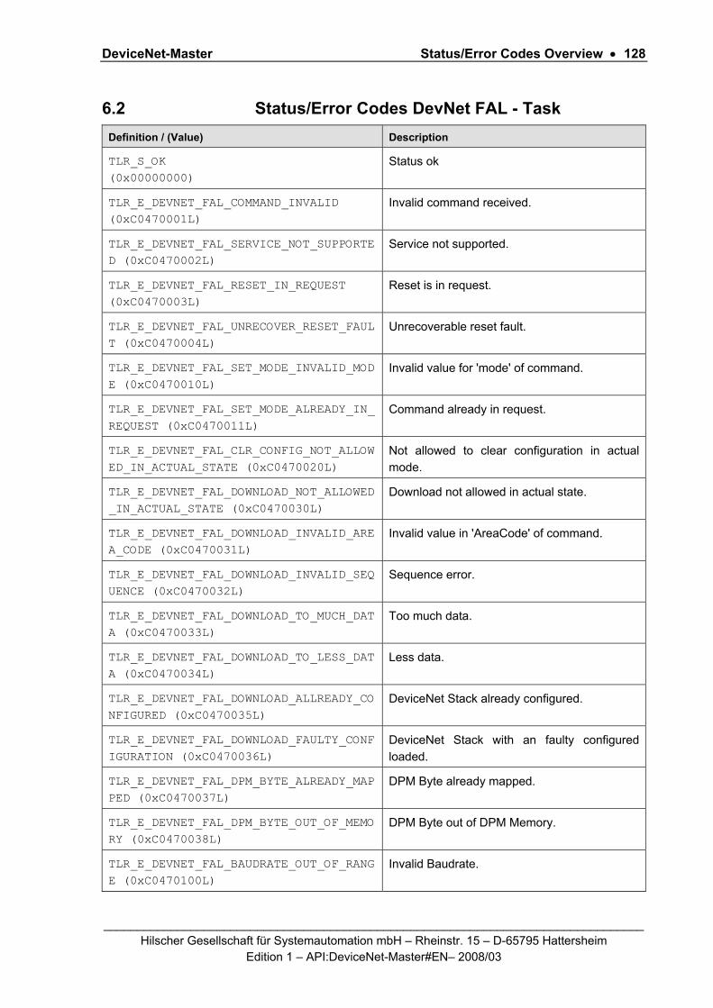
DeviceNet-Master Status/Error Codes Overview • 128
_________________________________________________________________________________ Hilscher Gesellschaft für Systemautomation mbH – Rheinstr. 15 – D-65795 Hattersheim
Edition 1 – API:DeviceNet-Master#EN– 2008/03
6.2 Status/Error Codes DevNet FAL - Task Definition / (Value) Description
TLR_S_OK (0x00000000)
Status ok
TLR_E_DEVNET_FAL_COMMAND_INVALID (0xC0470001L)
Invalid command received.
TLR_E_DEVNET_FAL_SERVICE_NOT_SUPPORTED (0xC0470002L)
Service not supported.
TLR_E_DEVNET_FAL_RESET_IN_REQUEST (0xC0470003L)
Reset is in request.
TLR_E_DEVNET_FAL_UNRECOVER_RESET_FAULT (0xC0470004L)
Unrecoverable reset fault.
TLR_E_DEVNET_FAL_SET_MODE_INVALID_MODE (0xC0470010L)
Invalid value for 'mode' of command.
TLR_E_DEVNET_FAL_SET_MODE_ALREADY_IN_REQUEST (0xC0470011L)
Command already in request.
TLR_E_DEVNET_FAL_CLR_CONFIG_NOT_ALLOWED_IN_ACTUAL_STATE (0xC0470020L)
Not allowed to clear configuration in actual mode.
TLR_E_DEVNET_FAL_DOWNLOAD_NOT_ALLOWED_IN_ACTUAL_STATE (0xC0470030L)
Download not allowed in actual state.
TLR_E_DEVNET_FAL_DOWNLOAD_INVALID_AREA_CODE (0xC0470031L)
Invalid value in 'AreaCode' of command.
TLR_E_DEVNET_FAL_DOWNLOAD_INVALID_SEQUENCE (0xC0470032L)
Sequence error.
TLR_E_DEVNET_FAL_DOWNLOAD_TO_MUCH_DATA (0xC0470033L)
Too much data.
TLR_E_DEVNET_FAL_DOWNLOAD_TO_LESS_DATA (0xC0470034L)
Less data.
TLR_E_DEVNET_FAL_DOWNLOAD_ALLREADY_CONFIGURED (0xC0470035L)
DeviceNet Stack already configured.
TLR_E_DEVNET_FAL_DOWNLOAD_FAULTY_CONFIGURATION (0xC0470036L)
DeviceNet Stack with an faulty configured loaded.
TLR_E_DEVNET_FAL_DPM_BYTE_ALREADY_MAPPED (0xC0470037L)
DPM Byte already mapped.
TLR_E_DEVNET_FAL_DPM_BYTE_OUT_OF_MEMORY (0xC0470038L)
DPM Byte out of DPM Memory.
TLR_E_DEVNET_FAL_BAUDRATE_OUT_OF_RANGE (0xC0470100L)
Invalid Baudrate.

DeviceNet-Master Status/Error Codes Overview • 129
_________________________________________________________________________________ Hilscher Gesellschaft für Systemautomation mbH – Rheinstr. 15 – D-65795 Hattersheim
Edition 1 – API:DeviceNet-Master#EN– 2008/03
Definition / (Value) Description
TLR_E_DEVNET_FAL_MAC_ID_OUT_OF_RANGE (0xC0470101L)
Invalid MAC ID.
TLR_E_DEVNET_FAL_ADR_DOUBLE (0xC0470102L)
Slave already configured.
TLR_E_DEVNET_FAL_DATA_SET_FIELD_LEN (0xC0470103L)
Invalid length of slave parameter set.
TLR_E_DEVNET_FAL_PRED_MST_SL_ADD_LEN (0xC0470104L)
Invalid length of address table in parameter set.
TLR_E_DEVNET_FAL_PRED_MSTSL_CFG_FIELD_LEN (0xC0470105L)
Invalid length of predefined master slave config table in parameter set.
TLR_E_DEVNET_FAL_PRED_MST_SL_ADD_TAB_INCONS (0xC0470106L)
Inconsistency between address table and configured connection length.
TLR_E_DEVNET_FAL_EXPL_PRM_FIELD_LEN (0xC0470107L)
Invalid Length of explicit parameter data in slave parameter set.
TLR_E_DEVNET_FAL_PRED_MSTSL_CFG_ADD_INPUT_INCONS (0xC0470108L)
Inconsistency between number of input address offsets and configured input modules.
TLR_E_DEVNET_FAL_PRED_MSTSL_CFG_ADD_OUTPUT_INCONS (0xC0470109L)
Inconsistency between number of output address offsets and configured output modules.
TLR_E_DEVNET_FAL_UNKNOWN_DATA_TYPE (0xC047010AL)
Unknown data type in of the module definition.
TLR_E_DEVNET_FAL_MODULE_DATA_SIZE (0xC047010BL)
Invalid data size in of the module definition.
TLR_E_DEVNET_FAL_OUTPUT_OFF_RANGE (0xC047010CL)
Output address offset exceeds the maximum allowed area.
TLR_E_DEVNET_FAL_INPUT_OFF_RANGE (0xC047010DL)
Input address offset exceeds the maximum allowed area.
TLR_E_DEVNET_FAL_WRONG_TYPE_OF_CONNECTION (0xC047010EL)
Invalid type of connection configured.
TLR_E_DEVNET_FAL_TYPE_CONNECTION_REDEFINITION (0xC047010FL)
Redefinition of connection type.
TLR_E_DEVNET_FAL_EXP_PACKET_LESS_PROD_INHIBIT (0xC0470110L)
Configured 'Production Inhibit Time' is smaller then 'Expected Packet Rate'.
TLR_E_DEVNET_FAL_PRM_FIELD_LEN_INCONSISTENT (0xC0470111L)
Invalid length of parameter field in slave parameter set.
TLR_E_DEVNET_FAL_SET_BAUDRATE_FAIL (0xC0470112L)
Error while setting baudrate.
TLR_E_DEVNET_FAL_REG_FRAG_TIMEOUT_OUT_OF_RANGE (0xC0470113L)
Invalid value of fragmentation timeout.

DeviceNet-Master Status/Error Codes Overview • 130
_________________________________________________________________________________ Hilscher Gesellschaft für Systemautomation mbH – Rheinstr. 15 – D-65795 Hattersheim
Edition 1 – API:DeviceNet-Master#EN– 2008/03
Definition / (Value) Description
TLR_E_DEVNET_FAL_PRM_OUT_MEMORY (0xC0470114L)
Out of memory for configuration data.
TLR_E_DEVNET_FAL_CON_NA (0xC0470211L)
No response from device.
TLR_E_DEVNET_FAL_CON_MDA (0xC0470215L)
Too much data received.
TLR_E_DEVNET_FAL_CON_LE (0xC0470233L)
Invalid length of requested service.
TLR_E_DEVNET_FAL_CON_AD (0xC0470236L)
Another service still active.
LR_E_DEVNET_FAL_CON_SE (0xC0470239L)
Sequence error in response sequence.
TLR_E_DEVNET_FAL_CON_OC (0xC0470240L)
Explicite Message Handler is occupied.
TLR_E_DEVNET_FAL_CON_ERR_RES (0xC0470294L)
Service Error Response.
TLR_E_DEVNET_FAL_LIFELIST_IN_PROGRESS (0xC0470295L)
Lifelist request in progress.
TLR_E_DEVNET_FAL_BTS_IN_PROGRESS (0xC0470296L)
Bit-strobe request in progress.
TLR_E_DEVNET_FAL_SLAVE_NOEXCHANGE (0xC0471000L)
Service Error Response.
Table 98: Status/Error Codes DevNet FAL - Task

DeviceNet-Master Status/Error Codes Overview • 131
_________________________________________________________________________________ Hilscher Gesellschaft für Systemautomation mbH – Rheinstr. 15 – D-65795 Hattersheim
Edition 1 – API:DeviceNet-Master#EN– 2008/03
6.3 Status/Error Codes CAN DL - Task Definition / (Value) Description
TLR_S_OK (0x00000000)
Status ok
TLR_E_CAN_DL_COMMAND_INVALID (0xC03F0001L)
Invalid command.
TLR_E_CAN_DL_CMD_LENGTH_MISMATCH (0xC03F0002L)
The length code of the command is invalid.
TLR_E_CAN_DL_UNKNOWN_PARAMETER_TYPE (0xC03F0003L)
The parameter type of the command "Set Parameter" is invalid.
TLR_E_CAN_DL_SET_MODE_FAILED (0xC03F0004L)
Within the command "Set Parameter" the function set "CAN Mode" failed.
TLR_E_CAN_DL_SET_BAUDRATE_FAILED (0xC03F0005L)
Within the command "Set Parameter" the function set "Baudrate" failed.
TLR_E_CAN_DL_SET_TXABORT_TIME_FAILED (0xC03F0006L)
Within the command "Set Parameter" the function set "Transmission Abort Timer" failed.
TLR_E_CAN_DL_SET_EVENTS_REQUESTED_FAILED (0xC03F0007L)
Within the command "Set Parameter" the function set "Requested Events" failed.
TLR_E_CAN_DL_SET_FILTER_FAILED (0xC03F0008L)
Within the command "Set Parameter" or "Set Filter the function set "CAN Filter" failed.
TLR_E_CAN_DL_SET_ENABLE_DISABLE_RXID_FAILED (0xC03F0009L)
Within the command Enable or Disable of receive identifiers an error occurred.
TLR_E_CAN_DL_TX_FRAME_FAILED (0xC03F000AL)
At least one CAN frame could not be sent. Normally because the send process was aborted by the transmission abort timer.
TLR_E_CAN_DL_TX_BUFFER_OVERRUN (0xC03F000BL)
The send request of CAN frames was rejected because the internal buffer for send requests is full.
TLR_E_CAN_DL_UNKNOWN_DIAG_TYPE (0xC03F000CL)
The diagnostic type of the command "Get Diag" is invalid.
TRL_E_CAN_DL_TX_ABORT_ALREADY_IN_REQUEST (0xC03F000DL)
The command "Transmission Abort" is already requested.
TRL_E_CAN_DL_TX_ABORT (0xC03F000EL)
The send process of can frames was aborted by "Transmission Abort" command.
Table 99: Status/Error Codes CAN DL - Task

DeviceNet-Master Contact • 132
_________________________________________________________________________________ Hilscher Gesellschaft für Systemautomation mbH – Rheinstr. 15 – D-65795 Hattersheim
Edition 1 – API:DeviceNet-Master#EN– 2008/03
7 Contact Headquarters Germany Hilscher Gesellschaft für Systemautomation mbH Rheinstrasse 15 65795 Hattersheim Phone: +49 (0) 6190 9907-0 Fax: +49 (0) 6190 9907-50 E-Mail: [email protected] Support Phone: +49 (0) 6190 9907-99 E-Mail: [email protected] Subsidiaries China Hilscher Ges.f.Systemaut. mbH Shanghai Representative Office 200010 Shanghai Phone: +86 (0) 21-6355-5161 E-Mail: [email protected] Support Phone: +86 (0) 21-6355-5161 E-Mail: [email protected] France Hilscher France S.a.r.l. 69500 Bron Phone: +33 (0) 4 72 37 98 40 E-Mail: [email protected] Support Phone: +33 (0) 4 72 37 98 40 E-Mail: [email protected] Italy Hilscher Italia srl 20090 Vimodrone (MI) Phone: +39 02 25007068 E-Mail: [email protected] Support Phone: +39 / 02 25007068 E-Mail: [email protected]
Japan Hilscher Japan KK Tokyo, 160-0022 Phone: +81 (0) 3-5362-0521 E-Mail: [email protected] Support Phone: +81 (0) 3-5362-0521 E-Mail: [email protected] Switzerland Hilscher Swiss GmbH 4500 Solothurn Phone: +41 (0) 32 623 6633 E-Mail: [email protected] Support Phone: +49 (0) 6190 9907-99 E-Mail: [email protected] USA Hilscher North America, Inc. Lisle, IL 60532 Phone: +1 630-505-5301 E-Mail: [email protected] Support Phone: +1 630-505-5301 E-Mail: [email protected]