Adaptive Inflatable Structures for protecting wind turbines against ...

1
Protection of wind energy systems against the indirect effects of lightning
R.B. Rodrigues a, V.M.F. Mendes a, J.P.S. Catalão b,c,*
a Departmental Area of Electrical Engineering and Automation, Instituto Superior de Engenharia de Lisboa, R. Conselheiro Emídio
Navarro, 1950-062 Lisbon, Portugal b Department of Electromechanical Engineering, University of Beira Interior, R. Fonte do Lameiro, 6201-001 Covilha, Portugal
c Center for Innovation in Electrical and Energy Engineering, Instituto Superior Técnico, Technical University of Lisbon, Av. Rovisco Pais, 1049-001 Lisbon, Portugal
Received 17 October 2010; received in revised form 30 March 2011
Abstract
This paper is concerned with the protection of wind energy systems against the indirect effects of lightning. As wind energy is gaining increasing importance throughout the world, lightning damages involving wind energy systems have come to be regarded with more attention. Nevertheless, there are still very few studies in Portugal regarding lightning protection of wind energy systems using models of the Electro-Magnetic Transients Program (EMTP). Hence, a new case study is presented in this paper, based on a wind turbine with an interconnecting transformer, considering that lightning strikes the soil near the tower at a distance such that galvanic coupling occurs through the grounding electrode. Computer simulations obtained by using EMTP-RV are presented and conclusions are duly drawn. © 2011 Elsevier Ltd. All rights reserved. Keywords: Electromagnetic transients; Lightning protection; Wind energy
1. Introduction
Renewable energy sources, especially wind energy, are widely applied as a mean to reach emission
reduction [1]. Hence, it is expected that wind energy will turn out to be an important part of the future
energy policy for Portugal [2,3], increasing significantly the share of renewable energy sources in the
overall generation mix at the expense of the conventional fossil energies [4].
In Portugal, the wind power goal foreseen for 2010 was established by the government as 3750 MW and
that will constitute some 25% of the total installed capacity by 2010. This value has recently been raised to
5100 MW, by the most recent governmental goals for the wind sector. Hence, Portugal has one of the most
ambitious goals in terms of wind power, and in 2006 was the second country in Europe with the highest
wind power growth [5,6].
As wind power generation undergoes rapid growth, lightning damages involving wind energy systems
have come to be regarded with more attention [7-10].
* Corresponding author at: Department of Electromechanical Engineering, University of Beira Interior, R. Fonte do Lameiro, 6201-001 Covilha, Portugal. Tel.: +351 275 329914; fax: +351 275 329972.
E-mail address: [email protected] (J.P.S. Catalão).

2
Lightning is in fact a tremendous phenomenon of nature, as beautiful as dangerous. Fig. 1 shows Lisbon
under a storm in 2009. The incidence of lightning strokes is a very serious problem [11], as it can produce
dangerous overvoltages [12].
"See Fig. 1 at the end of the manuscript".
Lightning protection of wind energy systems presents problems that are not normally seen with other
structures. These problems are a result of the following [13]:
• wind turbines are tall structures of more than 150 m in height;
• wind turbines are frequently placed at locations very exposed to lightning;
• the most exposed wind turbine components such as blades and nacelle cover are often made of composite
materials incapable of sustaining direct lightning stroke or of conducting lightning current;
• the blades and nacelle are rotating;
• the lightning current has to be conducted through the wind turbine structure to the ground, whereby
significant parts of the lightning current will pass through or near to practically all wind turbine
components;
• wind turbines in wind farms are electrically interconnected and often placed at locations with poor
grounding conditions.
When lightning hits a wind energy system without the proper protection, damages are often severe.
Fig. 2 shows a wind turbine in Portugal damaged by lightning [14].
"See Fig. 2 at the end of the manuscript".
Modern wind turbines are characterized not only by greater heights but also by the presence of ever-
increasing control and processing electronics. Consequently, the design of the lightning protection of
modern wind turbines will be a challenging problem [15]. The future development of wind power
generation and the construction of more wind farms will necessitate intensified discussion of lightning
protection and the insulation design of such facilities [16]. Nevertheless, there are still very few studies in
Portugal regarding lightning protection of wind energy systems using models of the Electro-Magnetic
Transients Program (EMTP). Also, surge propagation during lightning strikes at wind farms located in
Portugal is still far from being clearly understood, given that the Portuguese Lightning Location System
(LLS) is in operation only since 2003, thus much work remains to be done in this area.

3
Direct and indirect lightning strokes can produce damages on electrical and electronic systems, as well
as of mechanical components such as blades and bearings [17]. The events on low-voltage circuits are not
triggered by only direct lightning strikes but also induced lightning and back-flow surges propagating
around wind farms just after lightning strikes on other wind power generators [18]. Thus, an effective
lightning protection system should protect not only against the direct effects of lightning, but also against
its indirect effects. The possible damages due to overvoltage transients induced by indirect lightning strikes
are thoroughly studied in this paper, which is a new contribution to earlier studies.
Scale models of electrical systems have been a popular tool, especially in the past, to predict power
system transients after different types of perturbations [19]. For instance, a 3/100-scale model of an actual
wind energy system that has blades with a length of 25 m and a turbine that is 50 m high was considered in
[20, 21] for experimental and analytical studies of lightning overvoltages. However, in recent years, scale
models have been progressively replaced by sophisticated numerical codes, capable of describing the
transient behavior of power systems in an accurate way, such as the EMTP-RV, which designates the latest
version of the EMTP, while RV stands for Restructured Version [22].
A new case study is presented in this paper, based on a wind turbine with an interconnecting
transformer, considering that lightning strikes the soil near the tower at a distance such that galvanic
coupling occurs through the grounding electrode. Computer simulations obtained by using EMTP-RV are
presented and conclusions are duly drawn.
This paper is organized as follows. Section 2 presents the description of the wind turbine. Section 3
explains the EMTP models. Section 4 presents the case study and the simulation results. Finally,
concluding remarks are given in Section 5.
2. Wind turbine description
A wind turbine with 2 MW of rated power is considered. The rotor diameter is about 82 m. The rotor
hub and annular generator are directly connected to each other as a fixed unit without gears. The rotor unit
is mounted on a fixed axle. The drive system has only two slow-moving roller bearings due to the low
speed of the direct drive. The annular generator is a low-speed synchronous generator with no direct grid
coupling. Hence, the output voltage and frequency vary with the speed, implying the need for a converter
via a DC link in order to make a connection to the electric grid. The hub height varies between 70 to 138
m. The tubular steel turbine is manufactured in several individual turbine sections connected using stress
reducing L-flanges.

4
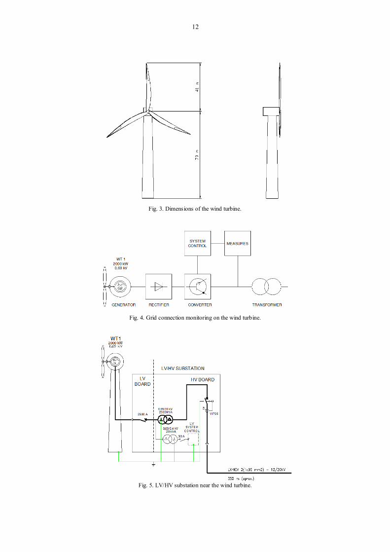
The LV/HV transformer is placed at the bottom of the turbine. It has 2500 kVA of rated power and has
a special design to fit the reduced dimensions and working conditions of the turbine. The wind turbine
shown in Fig. 3 was modeled in 3D with AutoCAD.
"See Fig. 3 at the end of the manuscript".
Ensuring proper power feed from the wind turbine into the grid requires grid connection monitoring,
shown in Fig. 4.
"See Fig. 4 at the end of the manuscript".
Fig. 5 shows the electric schema of a LV/HV substation near the wind turbine.
"See Fig. 5 at the end of the manuscript".
The following assumptions are made for the wind turbine model:
• the wind power generator, rectifier, and inverter (power conditioner) are treated as a unit, specifically, as
a 690 V synchronous generator that is sufficiently stable at 50 Hz;
• a 690 V / 20 kV boost transformer is placed inside the wind turbine or installed rather close to the wind
turbine. In addition, joint grounding of the primary and secondary side is assumed;
• in the transformer model, only electromagnetic transfer is considered, and static transfer is ignored;
• as a first approach, no lightning arresters to protect control circuits are connected to the primary side
(low-voltage side) or secondary side (high-voltage side, power grid side) of the boost transformer. This
will allow evaluating afterwards its real need;
• interconnection to the power grid is through a 20/60 kV transformer;
• the grounding resistance considered for the electrode in the absence of lightning currents is 1 Ω.
In addition, a standard lightning current waveform is assumed with wave front duration of 10 μs, wave-
tail duration of 350 μs, and a peak value of 10 kA. This is because, in Portugal, 80% of lightning strikes
have a peak current higher than 8-10 kA [3]. Lightning strikes the soil near the tower at a distance such that
galvanic coupling occurs through the grounding electrode.
3. EMTP models
The EMTP has been used to study transients in large scale power systems or in arbitrary electrical
networks. In this paper the most recent version, EMTP-RV, is applied. The complete software is also
named EMTP/EMTPWorks, where EMTP designates the computational engine. The following explains
briefly the most important models used in this paper.

5
3.1 Lightning current source
The ICIGRE device is an EMTP-RV model that was chosen to simulate the current lightning source.
This device is used for accurate calculations of the lightning performance of equipment. A complete
description of this model and the reasoning behind the provided analytical representation of the current
shape can be found in [22], from where the following equations were taken.
The current front of the first stroke is given by:
nBtAtI (1)
where:
m
n
max St
In9.0
1n1
A (2)
maxnmnn
I9.0tS1nt
1B
(3)
The current tail equation is given by:
2
n
1
n
ttt
2t
tt
1 eIeII
(4)
Equation (4) is used when EMTP enters the tail zone at startn ttt .
3.2 Wind turbine structure
To model the blade and the tower of a wind turbine, the Constant Parameter (CP) line is used, which is a
frequency independent transmission line model. For the purpose of this paper, the CP line model can be
successfully used. The frequency dependence of the parameters was also not considered in [23], because
the authors concluded that it has scarce influence on the transient responses of the tower system. Besides,
the same remark is provided in [24], where the frequency dependence of the parameters is again not
considered, since some studies have shown that the skin effect has little influence on the lightning transient
response.
The CP line is a distributed parameter model. The basic equations of the single phase distributed
parameter line are:
dt
t,xdI'Lt,xI'Rdx
t,xdV (5)
dt
t,xdV'Ct,xV'Gdx
t,xdI (6)

6
The CP line parameters are calculated at a given frequency, which is better to take it above 1MHz
[20,21], and that is why it is labeled as frequency independent. The CP line parameters were calculated
taking into account technical information from the manufacturer, such as, material characteristics and
dimensions of components.
3.3 Ground electrode
Precise modeling of the dynamic performance of grounding electrodes under lightning currents must
include both the time-dependent nonlinear soil ionization and the frequency-dependent phenomena. These
phenomena might have mutually opposing effects since the soil ionization effectively improves the
grounding performance, while frequency-dependent inductive behavior impairs it.
In the case of lightning, the current that is injected in the grounding electrodes is a fast-varying current
pulse with high peak values. The dynamic response of the grounding electrodes subjected to such current
pulses is predominantly influenced by:
• the soil ionization in the immediate proximity of the grounding electrode, which is related to the current
pulse intensity;
• the lightning pulse propagation along the grounding electrode, which is related to the current pulse front
time.
The ground electrode model used in this paper is very often used with lightning simulation purposes for
HV transmission lines and towers. It considers a nonlinear resistance using controlled resistance and
admittance. The presence of the current source provides an option for creating a piecewise linear resistance
function. Any segment k of such a function can be represented by the Norton circuit equivalent:
kkkk IvYi (7)
The kY is actually the derivative at the operating point k:
k
kk v
iY
(8)
When using the same ground electrode for safety and service purposes, the Portuguese regulation
requires a maximum value for earth resistance of 1. This value is assumed in the absence of lightning
current flowing through it.

7
3.4 Surge arrester
The basic arrester model equation [22] is given by (9), where ai is the arrester current and av is the
arrester voltage:
aa vki (9)
For SiC (Silicon Carbide) arresters the value of is between 2 to 6. For MO (Metal Oxide) arresters
the value is 6010 . The k parameter is a constant used in fitting the arrester characteristic.
4. Simulation results
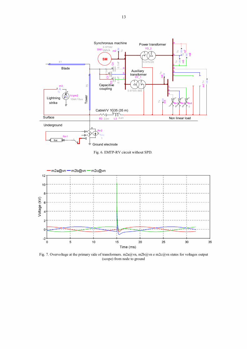
In a first approach, the EMTP-RV circuit is considered without SPD, as shown in Fig. 6. Inside the wind
turbine a 690 VRMS generator (SM) produces electrical energy which is delivered to the main power
transformer (YD_2) and to the auxiliary transformer (DY_1). The DY_1 transformer feeds electronic
control equipment (Rn1, Rn3 and Rn4).
"See Fig. 6 at the end of the manuscript".
Lightning strikes the soil near the tower. Fig. 7 presents the shape of the overvoltage at the primary side
of transformers, where "m" stands for measure and "a, b, c" stands for phases L1, L2 and L3. The peak
value of overvoltage surpasses 10 kV.
"See Fig. 7 at the end of the manuscript".
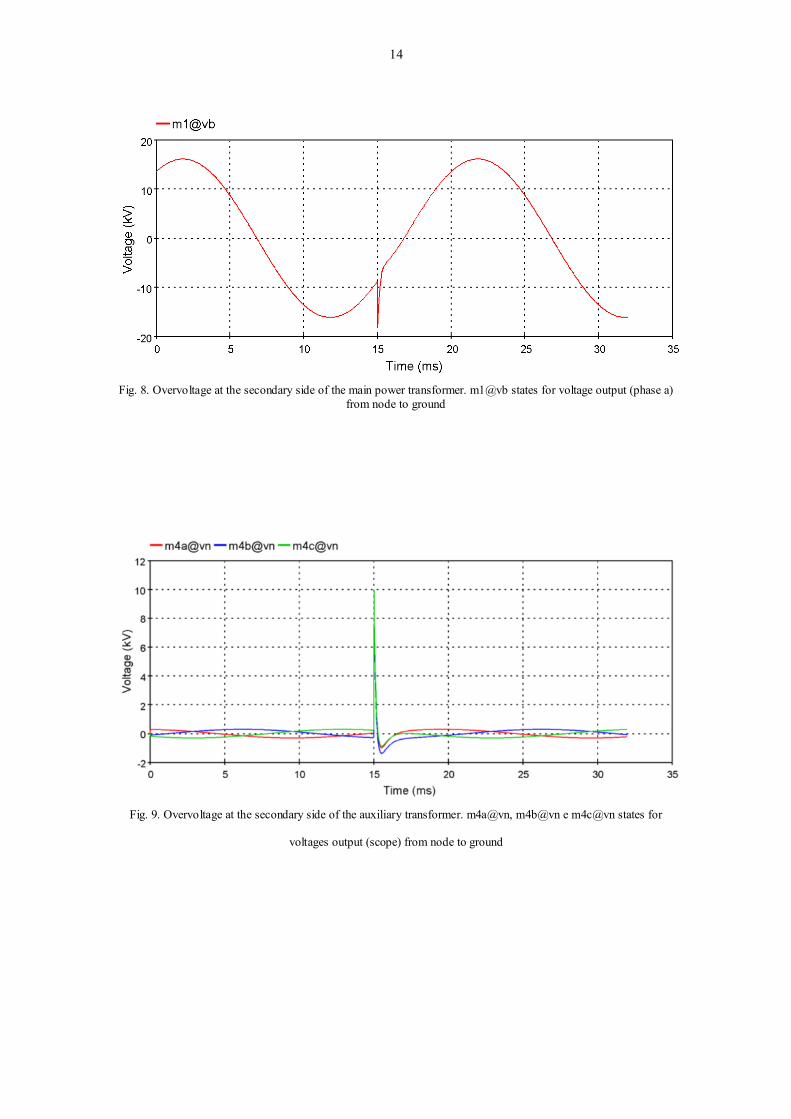
Fig. 8 presents the shape of the overvoltage at the secondary side of the main power transformer.
"See Fig. 8 at the end of the manuscript".
Fig. 9 presents the shape of the overvoltages at the electronic control equipment. The peak value of
overvoltage reaches almost 10 kV, which is more than this kind of equipment can support.
"See Fig. 9 at the end of the manuscript".
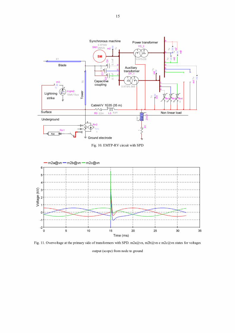
In these conditions, an adequate surge protective device (SPD) is necessary to limit the voltage below
1500 V, as shown in Fig. 10.
"See Fig. 10 at the end of the manuscript".
Fig. 11 presents the shape of the overvoltage at the primary side of transformers with a SPD installed.
The peak value of overvoltage decreases to approximately 5 kV.
"See Fig. 11 at the end of the manuscript".

8
Fig. 12 presents the shape of the overvoltage at the secondary side of the main power transformer. The
peak value of overvoltage is inferior, but still noticeable.
"See Fig. 12 at the end of the manuscript".
Fig. 13 presents the shape of the overvoltages at the electronic control equipment with SPD. The peak
value of overvoltage reaches almost 6 kV, which is still more than this kind of equipment can support.
"See Fig. 13 at the end of the manuscript".
Only with a perfect SPD connection the overvoltage could remain below the upper limit supported by
the control equipment, as will be shown hereafter.
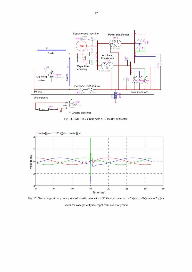
The EMTP-RV circuit with SPD ideally connected is shown in Fig. 14.
"See Fig. 14 at the end of the manuscript".
Fig. 15 presents the shape of the overvoltage at the primary side of transformers with SPD ideally
connected. The peak value of overvoltage decreases to less than 4 kV.
"See Fig. 15 at the end of the manuscript".
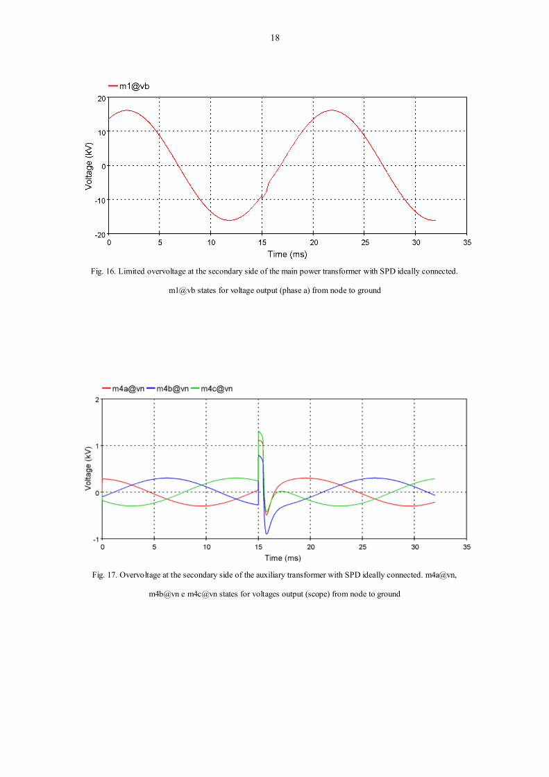
Fig. 16 presents the shape of the overvoltage at the secondary side of the main power transformer. The
peak value of overvoltage is now negligible.
"See Fig. 16 at the end of the manuscript".
Finally, Fig. 17 presents the shape of the overvoltages at the electronic control equipment with SPD
ideally connected. The peak value of overvoltage is now below 1500 V, so the control equipment is safe.
"See Fig. 17 at the end of the manuscript".
5. Conclusions
This paper presents a case study, based on a wind turbine with an interconnecting transformer, for the
analysis of lightning surges. The most recent international standards have been used in this work. Also,
computer simulations are obtained by using the most recent EMTP version, the EMTP-RV. Reference
values of international standards have been adapted to Portuguese reality. Nevertheless, results are also true
for other countries. A lightning current with 10 kA of peak value has been considered stroking the ground
near the tower. The peak value of the overvoltage reaches almost 6 kV at the electronic control equipment,
even with a SPD installed. This occurs because the connection of SPD to ground is not ideal. To reduce the
overvoltage to an acceptable value, SPD in differential mode could be installed. Nevertheless, the SPD
considered is sufficient to reduce the overvoltage at the high-voltage branch of the main power

9
transformer. The computer simulations have proven to be very helpful on finding which are the most
adequate protection measures, and where they must be located, thus avoiding downtime production and
saving money.
Acknowledgements
The authors would like to thank Prof. A. Machado e Moura for his valuable comments.
References
[1] Kuo C-C. Wind energy dispatch considering environmental and economic factors. Renew. Energy 2010;
35:2217–27.
[2] Rodrigues RB, Mendes VMF, Catalão JPS. Estimation of lightning vulnerability points on wind power plants
using the rolling sphere method. J. Electrost. 2009; 67:774–80.
[3] Rodrigues RB, Mendes VMF, Catalão JPS. Lightning data observed with lightning location system in Portugal.
IEEE Trans. Power Delivery 2010; 25:870–5.
[4] González JS, Rodriguez AGG, Mora JC, Santos JR, Payan MB. Optimization of wind farm turbines layout using
an evolutive algorithm. Renew. Energy 2010; 35:1671–81.
[5] Melício R, Mendes VMF, Catalão JPS. Power converter topologies for wind energy conversion systems:
Integrated modeling, control strategy and performance simulation. Renew. Energy 2010; 35:2165–74.
[6] Catalão JPS, Pousinho HMI, Mendes VMF. Short-term wind power forecasting in Portugal by neural networks
and wavelet transform. Renew. Energy 2011; 36:1245–51.
[7] Liu W, Tang B, Jiang Y. Status and problems of wind turbine structural health monitoring techniques in China.
Renew. Energy 2010; 35:1414–8.
[8] Hameed Z, Ahn SH, Cho YM. Practical aspects of a condition monitoring system for a wind turbine with
emphasis on its design, system architecture, testing and installation. Renew. Energy 2010; 35:879–94.
[9] Ukar O, Zamora I. Wind farm grounding system design for transient currents. Renew. Energy 2011; 36:2004–10.
[10] Yasuda Y, Uno N, Kobayashi H, Funabashi T. Surge analysis on wind farm when winter lightning strikes. IEEE
Trans. Energy Convers. 2008; 23:257–62.
[11] Glushakow B. Effective lightning protection for wind turbine generators. IEEE Trans. Energy Convers. 2007;
22:214–22.
[12] Hameed Z, Ahn SH, Cho YM. Practical aspects of a condition monitoring system for a wind turbine with
emphasis on its design, system architecture, testing and installation. Renew. Energy 2010; 35:879–94.
[13] IEC, Wind turbine generator systems—Part 24: Lightning protection, TR 61400-24, 2002.
[14] Rodrigues RB, Mendes VMF, Catalão JPS. Electromagnetic transients analysis of lightning overvoltages on
wind power plants. International Review of Electrical Engineering-IREE 2010; 5:1424–9.
[15] Rachidi F, Rubinstein M, Montanyà J, Bermúdez J-L, Sola RR, Solà G, Korovkin N. A review of current issues
in lightning protection of new-generation wind-turbine blades. IEEE Trans. Industrial Electronics 2008; 55:2489–96.
[16] Yasuda Y, Hara T, Funabashi T. Analysis of lightning surge propagation in wind farm. Electr. Eng. Jpn. 2008;
162:30–8.
[17] Cotton I, Jenkins N, Pandiaraj K. Lightning protection for wind turbine blades and bearings. Wind Energy 2001;
4:23–37.

10
[18] Yasuda Y, Funabashi T. Transient analysis on wind farm suffered from lightning. Proc. 39th Int. Univ. Power
Eng. Conf. 2004; 202–6.
[19] Piantini A, Janiszewski JM, Borghetti A, Nucci CA, Paolone M. A scale model for the study of the LEMP
response of complex power distribution networks. IEEE Trans. Power Deliv. 2007; 22:710–20.
[20] Yamamoto K, Noda T, Yokoyama S, Ametani A. An experimental study of lightning overvoltages in wind
turbine generation systems using a reduced-size model. Electr. Eng. Jpn. 2007; 158:65–72.
[21] Yamamoto K, Noda T, Yokoyama S, Ametani A. Experimental and analytical studies of lightning overvoltages
in wind turbine generator systems. Electr. Power Syst. Res. 2009; 79:436–42.
[22] Mahseredjian J, Dewhurst C. Using EMTP Tutorials and Reference 2008.
[23] Wang XH, Zhang XQ, Yang DS. An efficient algorithm of transient responses on wind turbine towers struck by
lightning. Compel-Int. J. Comp. Math. Electr. Electron. Eng. 2009; 28:372–84.
[24] Wang XH, Zhang XQ, Yang DS. Calculation of electromagnetic induction inside a wind turbine tower struck by
lightning. Wind Energy 2009; DOI: 10.1002/we.382.

11
Figure captions
Fig. 1. Lightning over Lisbon in 2009.
Fig. 2. Wind turbine in Portugal damaged by lightning.
12
Fig. 3. Dimensions of the wind turbine.
Fig. 4. Grid connection monitoring on the wind turbine.
Fig. 5. LV/HV substation near the wind turbine.
13
Fig. 6. EMTP-RV circuit without SPD.
Fig. 7. Overvoltage at the primary side of transformers. m2a@vn, m2b@vn e m2c@vn states for voltages output
(scope) from node to ground
Underground
Surface
CableVV 1G35 (35 m)
Towe
r
Blade
Lightning
Synchronous machine
Auxiliary
Power transformer
Non linear load
Ground electrode
Capacitive coupling
transformer
strike
+ Am3
?i
1 2DY_1
0.975/0.566
+R3 22m
+
L3
4uH
+
Icigre210kA/10us
VM +m2 ?v
+
0
Rn1
SM
0.975kV2MVA
SM1
VM
+?v m5
VM
+m4
?v
+ 0.1n
F C
4
+75
+
IY
IY
1?i>i
Rn2
if(u) 1 Fm1
+0.1n
F
C1
+
0.1n
F
C3
+
0
Rn3
+
0
Rn4
+41
VM+
?v m6
VM+
?v m7
VM+
?v m9
VM+
?vm
1
1 2YD_2
0.975/28
c
b
a
a
cb
c
c
b
b
a
a
14
Fig. 8. Overvoltage at the secondary side of the main power transformer. m1@vb states for voltage output (phase a)
from node to ground
Fig. 9. Overvoltage at the secondary side of the auxiliary transformer. m4a@vn, m4b@vn e m4c@vn states for
voltages output (scope) from node to ground
15
Fig. 10. EMTP-RV circuit with SPD
Fig. 11. Overvoltage at the primary side of transformers with SPD. m2a@vn, m2b@vn e m2c@vn states for voltages
output (scope) from node to ground
Underground
Surface
CableVV 1G35 (35 m)
Towe
r
Blade
Lightning
Synchronous machine
Auxiliary
Power transformer
Non linear load
Ground electrode
Capacitive coupling
transformer
strike
+ Am3
?i
1 2DY_1
0.975/0.566
+R3 22m
+
L3
4uH
+
Icigre210kA/10us
VM +m2 ?v
+
0
Rn1
SM
0.975kV2MVA
SM1
VM
+?v m5
VM
+m4
?v
+ 0.1n
F C
4
+75
+
IY
IY
1?i>i
Rn2
if(u) 1 Fm1
+0.1n
F
C1
+
0.1n
F
C3
+
0
Rn3
+
0
Rn4
+41
VM+
?v m6
VM+
?v m7
VM+
?v m9
VM+
?vm
1
1 2YD_2
0.975/28
+Z
nO
1kV
Zn
O1
+ R1
1
c
b
a
a
cb
c
c
b
b
a
a

16
Fig. 12. Limited overvoltage at the secondary side of the main power transformer with SPD. m1@vb states for
voltage output (phase a) from node to ground
Fig. 13. Overvoltage at the secondary side of the auxiliary transformer with SPD. m4a@vn, m4b@vn e m4c@vn
states for voltages output (scope) from node to ground
17
Fig. 14. EMTP-RV circuit with SPD ideally connected.
Fig. 15. Overvoltage at the primary side of transformers with SPD ideally connected. m2a@vn, m2b@vn e m2c@vn
states for voltages output (scope) from node to ground
Underground
Surface
CableVV 1G35 (35 m)
Tow
er
Blade
Lightning
Synchronous machine
Auxiliary
Power transformer
Non linear load
Ground electrode
Capacitive coupling
transformer
strike
+ Am3
?i
1 2DY_1
0.975/0.566
+R3 22m
+
L3
4uH
+
Icigre210kA/10us
VM +m2 ?v
+
0
Rn1
SM
0.975kV2MVA
SM1
VM
+?v m5
VM
+m4?v
+ 0.1n
F C
4
+75
+
IY
IY
1?i>i
Rn2
if(u) 1 Fm1
+0.1n
F
C1 +
0.1n
F
C3
+
0
Rn3
+
0
Rn4
+41
VM
+?v m
6V
M+
?v m7
VM+
?v m9
VM
+?v
m1
1 2YD_2
0.975/28
+Z
nO
1kV
Zn
O1
c
b
a
a
cb
c
c
b
b
a
a
18
Fig. 16. Limited overvoltage at the secondary side of the main power transformer with SPD ideally connected.
m1@vb states for voltage output (phase a) from node to ground
Fig. 17. Overvoltage at the secondary side of the auxiliary transformer with SPD ideally connected. m4a@vn,
m4b@vn e m4c@vn states for voltages output (scope) from node to ground