Propping and Jacking - Home | Mabey · PDF filePropping and Jacking all the support you need....
72
ISSUE 1 September 2013 Propping and Jacking all the support you need
Transcript of Propping and Jacking - Home | Mabey · PDF filePropping and Jacking all the support you need....

ISSUE 1 September 2013
Propping and Jackingall the support you need

1
Depots and worksMabey Hire’s nationwide network
Aberdeen01358 723 650
Bilston01902 404 512
Bury St.Edmunds01284 767 600
Cardiff02920 396 621
Calne01249 821 193
Dewsbury(Head Offi ce) 01924 460 601(Works) 01924 464 695
Durham0191 517 5600
Garswood(Depot) 01942 725 341(Contract Services) 01942 725 343
Glasgow0141 779 3535
Hatfi eld01707 267 171
Inverness01463 239 222
Newton Abbot01626 833 391
Nottingham0115 930 1154
Romsey01794 515 666
Strood01634 722 465
Twyford0118 9404 470
Wellingborough01933 441 155
1
2
3
4
5
6
7
8
9
10
11
12
13
14
15
16
17
11 1
9
7
68
13
2
173
10
1516
14
54
12

2England & Wales t: 0845 741 3040 Scotland: t: 0845 841 3040 www.mabeyhire.co.uk
Contents
Company 3
Welcome 3
Contract services 4
Engineering excellence 5
Safety first 6
Services 7
Knowledge at your fingertips 7
View your account 7
10te prop 8
Introduction 9
Prop fittings 10
Prop applications 11
System 160 12
Prop units 13
Properties 14
Prop length & capacities 15
Fittings 19
Needle beams & fittings 21
Properties 23
Mass 25 24
Prop units 25
Grillage beams 27
Properties 28
Fittings 29
Bracing 31
Mass 50 32
Prop units 33
Grillage beams 35
Properties 36
Fittings 37
Bracing 40
Bracing options 41
Mat 125 42
Column units 43
Joists 44
Properties 45
Fittings 46
Bracing 48
Superprop 50
Prop modules 51
Header beams 52
Bracing 53
Properties 54
Fittings 55
Hydraulics & jacking 56
Overview 57
Hymat jacks 58
Screw ram jacks 59
Plain ram jacks 60
Double acting / hollow ram jacks 61
Climbing jack system 62
Specialist monitoring & instrumentation 63
Structural monitoring 64
Working with Mabey Hire 65
Product areas 67
General overview 71

3
WelcomeOperating from the most expansive nationwide network of
depots and engineering offices, and serving a diverse range
of industry operators, Mabey Hire is a leading supplier of non
mechanical plant for hire and sale.
Providing engineered modular and proprietary temporary works
equipment for ground support, formwork, falsework, propping,
jacking, temporary bridging, roadbarriers and a wide range of
other systems, Mabey Hire are proud to have the most varied
product portfolio in this UK sector, supported by the most
skilled engineering teams.
We hold over half a century of experience in multiple
construction sectors and continue to invest and build on
this as one of our core values, to routinely exceed the
expectations of our clients and to remain at the forefront
of the UK’s non mechanical plant hire industry.
Working from 17 different locations across the UK, Mabey Hire
combines full UK coverage with specialised local solutions. Demonstrating our commitment to quality
and service, Mabey Hire operates the
ISO9001:2008 and ISO14001:2004.

4England & Wales t: 0845 741 3040 Scotland: t: 0845 841 3040 www.mabeyhire.co.uk
Our contracts division extends the level of service offered to
our clients by providing full subcontract design, supply and
installation packages managed by experienced, specialist in
house engineers and site teams.
From our Wigan location, we offer bridging, falsework, heavy
shoring, façade retention and vehicular restraint systems
providing safe, cost effective temporary works solutions.
Through our contract services division we aim to work hand in
hand with our clients from feasibility through the tender process
to contract and completion providing tailored innovative solutions
that regularly contribute to the success of a tender.
By providing a complete turnkey solution for temporary works
requirements we have established ourselves as a market leader
in the UK. We are able to reduce our clients commercial and
practical risks giving cost certainty and total peace of mind.
Contract services

5
Based out of 9 Depot locations our engineering teams are there
to provide expert technical support to you throughout the UK,
on a diverse range of projects.
Mabey Hire engineers are happy to work in close conjunction
with you and your teams, on projects that are more intricate than
average or perhaps are on a larger scale. These projects can
range from relatively small to highly bespoke solutions on unusual
projects.
Each area in the UK can have its own specific working
requirements such as unique ground conditions. Our engineering
teams are based throughout the UK and have built up a detailed
working knowledge of their local environment and bring this extra
experience to each project they work on.
All Mabey Hire engineers have extensive practical experience
gained within the construction industry, and use
state of the art computer systems for drafting and design to
maintain our stringent standards and to expedite the
response rate you receive.
Engineers with hands on construction experience
Localised engineers with local knowledge of the
working environment
Site visits as necessary from 9 strategically placed UK
locations
Experienced Groundworks, Formwork, Falsework
and Bridging and Refurbishment specialists
Contact our engineers directly or at
Engineering excellence

6England & Wales t: 0845 741 3040 Scotland: t: 0845 841 3040 www.mabeyhire.co.uk
Our Health and Safety is at the very heart of our business and
always will be. We are dedicated to ensuring that the services
and products we provide are the best available, therefore:
We ensure that all equipment is safety and quality checked
prior to every hire despatch and upon every off hire
We ensure that all equipment is thoroughly tested and
inspected with greater regularity than that required by law
We provide advice and guidance on using our equipment,
via data sheets, user and installation guides
We are OHSAS 18001 Health and Safety accredited
We have achieved a ROSPA Gold Award in two
consecutive years
Mabey Hire drivers have Hi-ab, banksman and slinging
certificates
We have 100% CSCS certification for staff visiting or working
on site. Our installation teams hold relevant CPCS and PASMA
cards together with PTS certification for rail work.
Safety first

7
Knowledge at your fi ngertipsOur website has been designed to give you instant 24/7
access to product information, contacts and enquiry
services meaning we are always within reach.
Features you can enjoy on our website include:
Full product range information
User guides
Recent projects information
News
New product launches
Brochure downloads
Technical information
Visit us at www.mabeyhire.co.uk
Don’t forget to join our online communities for instant
News and Updates!
MabeyHireLtd
@MabeyHire
We understand how important it is for you to be on top of your
hires and potential charges.
Our online view your account system allows you complete access
to real time account information making sure you always have
your current details at your fi ngertips.
Free to register, the view your account function is available to all
Mabey Hire account holders. This access allows you to:
View your hire contracts
View hire equipment by site
View invoice detail
Filter information to your personal preferences
Export information and reports to other systems
Visit your account or register at
www.mabeyhire.co.uk/viewyouraccount
View your account

8England & Wales t: 0845 741 3040 Scotland: t: 0845 841 3040 www.mabeyhire.co.uk
A simple efficient propping system designed specifically for
use in smaller needling and propping requirements.
10te Prop
Fittings
Applications
10te prop

9
The Mabey 10te prop is ideal for lighter needling and propping
requirements where the prop load is less than 100kN. Lighter than
an equivalent System 160 based prop, the 10te prop provides a
simple, easily constructed robust propping system.
System description
The Head Unit connects to the top of the vertical prop and by
fi tting the Connector Plate and Clamp Plates, a connection is
provided onto the horizontal Needle Beam. The Connector
Plate is free to move through 360º allowing the needle to be
located at any position on top of the prop. The washer N-002
does not clamp tight, but holds the Connector Plate captive
to the Head Unit. The Spacer, if required, is fi tted between the
prop and the jack.
Careful consideration must be given to
the lateral stability of the propping system
whilst under construction and in use.
S3/1-540 (System 160) prop units can
be fi tted between the Head Unit and
Connector Plate in order to connect
raking props, should they be required.
The maximum prop length under the
needle beams is 3215mm.
10te prop
Code no. Description Length(mm)
Weight(kg)
S3/56A/0.9 Prop 890 15.8
S3/56A/1.8 Prop 1790 29.1
S3/56A/2.7 Prop 2690 43.0
Leng
th
Typical needle beam to 10te prop connection
Needle beam
Connector plateCode no. N-001
Head unitCode no. S3/56B
2 No. M16 x 60 long galvanised bolts
Clamp plate Code no. N-003(both sides)
Pin & ‘R’ clipCode no. MHB-04
WasherCode no. N-002
System benefi ts
lighter propping loads
and lengths available
needle ensures stability
ease installation
scaffold tube
1 No. M16 x 45 long bolt Code no. S3/22(nut not required)

10England & Wales t: 0845 741 3040 Scotland: t: 0845 841 3040 www.mabeyhire.co.uk
Used to secure Head Unit S3/56B to
the prop unit. Positioned on top of the
prop units to allow the connection
of needle beam fi ttings.
Code: MHB-04
Weight: 0.6kg
Scaffold tube clampAllows prop units to be braced
with standard scaffold tube,
must be fi tted to the prop before
the S3/56B head unit.
Code: S3/56C
Weight: 3.8kg
Head unitCode: S3/56B
Weight: 7kg
SpacerFitted to the base of the
prop unit to give greater
fl exibility in prop lengths.
Code: S3/56D/0.36
Weight: 11.2kg
Code no. Description Length(mm)
Weight(kg)
S3/56D/0.36 Spacer 360 11.2
S3/56D/0.54 Spacer 540 13.8
S3/56D/0.72 Spacer 720 16.4
Spacer insitu
Adjustable base
Leng
th
180 225
120 120
180 230
150
Prop unit
Head unit insitu
Pin & ‘R’ clip
Code: MHB-04
Scaffold tube clamp insitu
Prop unit
Prop unit
10te adjustable baseUsed to allow height
adjustment, the base plate
will allow a 5 degree tilt in
any direction to cater for
uneven foundation surfaces.
Code: S3/57
Weight: 18kg
200
min
. / 5
00 m
ax.
180 230
End plate
Prop unit
Adjustable base insitu
180
75
75
75 75
230
Ø55
4x Ø182x Ø26

11
Mk3 prop beam
Web connectors S3/05
1335
min
./34
35m
ax.
Scaffold tube bracing
10te prop
S3/57
Scaffold tube bracing
S3/56A
S3/56C
Wall
1115
min
. / 3
215
max
.N
eedl
e de
pth
a) Needle Beams placed directly onto props and connected
using the Needle Beam Connector plate.
b) Alternatively, the Head Unit can be connected to a
horizontal Mk3 Prop Header Beam. The Needle Beam is
then positioned on the top of the Header Beam at 90° to it.
This arrangement allows the vertical props to be spaced at
greater centres than the Needle Beams.
Typical prop/needle beam arrangements

12England & Wales t: 0845 741 3040 Scotland: t: 0845 841 3040 www.mabeyhire.co.uk
A compact high load propping system offering a capacity of up to
200kN per prop. The system includes a comprehensive range of
accessories that together create a flexible and adaptable shoring
system suitable for a wide range of uses.
Prop units
Properties
Prop lengths and capacities
Fittings
System 160

13
System 160
Eight standard lengths up to 4500mm
Code no. Description Length(mm)
Weight(kg)
S3/1-4500 Prop unit 4500 101.0
S3/1-3600 Prop unit 3600 82.0
S3/1-2700 Prop unit 2700 62.5
S3/1-2340 Prop unit 2340 52.0
S3/1-1800 Prop unit 1800 40.0
S3/1-900 Prop unit 900 25.0
S3/1-540 Prop unit 540 15.7
S3/1-360 Prop unit 360 11.8
Note: Prop end connections are made by using 6 No. S3/22 M16GR8.8 bolts 45mm in length.
Typical cross section
170
60 50 60
230
End elevation
180
75
75
75 75
230
Ø55
6x Ø18
2 holes Ø12
101
360
540
900
1800
2700
3600
4500
S3/1-360
2340
S3/1-4500
90
180
System 160 prop units form the basis of this system. The unique design provides high load capacity in a compact
230mm x 180mm prop unit. Components are sized to allow
the system to be built by hand within existing structures
where required.
System 160 - prop units
System benefits
can be manhandled if necessary
and lengths available
throughout the country

14England & Wales t: 0845 741 3040 Scotland: t: 0845 841 3040 www.mabeyhire.co.uk
Note:1. When used in tension the Safe Working Load is 120kN.
2. Values assume that the load is applied concentrically along the centre of the prop ie no eccentricity.
3. For controlled situations where the loading is predictable a factor of safety of 1.7 may be used.
4. In horizontal applications, the capacity above may be used providing that the props are used with the soldier webs/lightening holes in the vertical plane.
5. Longer props can be braced to reduce the effective length and improve the capacity. Please refer to the System 160 Data Sheet.
6. All bolt joints require 6 no. S3/22 bolts.
7. Straightness requirement: When the prop is assembled, the maximum deviation from straight should be 2mm per metre length eg 10mm for a 5m prop. Should a prop fall outside this requirement, components should be checked for damage.
8. Limitations of End Fittings: Values may be limited by the type of end fittings used. In the absence of a standard end fitting, the load must be applied through a stiff surface such as a steel plate or uniform concrete surface.
9. Further information should be obtained from the product technical data sheets or Mabey Hire engineers.
0 2 4 6 8 10 12
0
50
100
150
200
250
Overall Prop Length (m)
Saf
e W
orki
ng A
xial
Loa
d w
ith F
.o.S
of 2
.0 (k
N)
Section modulus (Nett) 168cm3
Minimum cross sectional area through lightening holes
21cm2
Maximum cross sectional area 25cm2
Second moment of area 1940cm4
Maximum bending moment suitably restrained assuming no local point load
60kNm
Maximum moment of resistance at joint (6no M16 bolts)
25kNm
Maximum shear capacity 120kN

15
System 160
Mk3 prop unit
Adjustable base unit S3/09
Mk3 prop unit header beam
Head unit S3/10
Head unit S3/10A
Mk3 prop unit
Wor
king
ran
ge
Working range
System 160 - prop lengths & capacities
with fixed length head unit and adjustable base unit
Notes
1. The S3/10 is required in the vertical prop to make a connection
with another prop unit (as shown in the sketch above) add
2 x S3/05 Web Connectors and 2 x S3/21 bolts.
2. Alternative prop unit combinations may be used for the same
height ranges if the longer prop units are undesirable due to
handling considerations.
3. Depending on the working range required, the use of S3/1-540
prop units may be preferable.
4. It is important to avoid eccentric loading in the props. The
S3/09 Base Units and the S3/10 and S3/10A Head Units are
pinned about one axis only, so only crossfalls perpendicular to
the longitudinal axis of the pin are acceptable.
5. A kit assembly reference is given to assist in ordering the props.
The kit includes all parts and bolts necessary depending upon
the manner in which the prop is used.
Note: a kit assembly reference is given to assist in ordering the props. The kit includes all parts and bolts necessary depending upon the manner in which the prop is used. The kit assembly reference number must be followed by the A, B or C suffix i.e. a Type 9 Prop to support Mk2 Prop Units would be called off as S3/KP/9C.
S3/10 Use A - To prop Mk3 props S3/10A Use B - To prop vertical members other than props S3/10A Use C - To prop Mk2 props

16England & Wales t: 0845 741 3040 Scotland: t: 0845 841 3040 www.mabeyhire.co.uk
Working range
Adj. base S3/09
(318mm - 767mm)
Fixed head unit S3/10A 512mm
S3/ 1-360
S3/ 1-900
S3/ 1-1800
S31-2700
S3/ 1-3600
S3/ 1-4500
S3/22 Bolts
Kit assembly
ref.
Weight (kg)
859 - 1279 1 1 - - - - - - 4 S3/KP/1 50
1190 - 1639 1 1 1 - - - - - 8 S3/KP/2 62
1550 - 1999 1 1 2 - - - - - 12 S3/KP/3 76
1730 - 2179 1 1 - 1 - - - - 8 S3/KP/4 76
2090 - 2539 1 1 1 1 - - - - 12 - 88
2450 - 2899 1 1 2 1 - - - - 16 - 101
2630 - 3079 1 1 - - 1 - - - 8 S3/KP/5 91
2990 - 3439 1 1 1 - 1 - - - 12 - 103
3350 - 3799 1 1 2 - 1 - - - 16 - 116
3530 - 3979 1 1 - - - 1 - - 8 S3/KP/6 113
3890 - 4339 1 1 1 - - 1 - - 12 - 126
4250 - 4699 1 1 2 - - 1 - - 16 - 138
4430 - 4879 1 1 - - - - 1 - 8 S3/KP/7 133
4790 - 5239 1 1 1 - - - 1 - 12 - 145
5150 - 5599 1 1 2 - - - 1 - 16 - 158
5330 - 5779 1 1 - - - - - 1 8 S3/KP/8 152
5690 - 6139 1 1 1 - - - - 1 12 - 162
6050 - 6499 1 1 2 - - - - 1 16 - 177
6230 - 6679 1 1 - 1 - - - 1 12 S3/KP/9 177
6590 - 7039 1 1 1 1 - - - 1 16 - 190
6950 - 7399 1 1 2 1 - - - 1 20 - 203
7130 - 7579 1 1 - - 1 - - 1 12 S3/KP/10 193
7490 - 7939 1 1 1 - 1 - - 1 16 - 206
7850 - 8299 1 1 2 - 1 - - 1 20 - 234
8030 - 8479 1 1 - - 2 - 1 - 16 S3/KP/11 214
8390 - 8839 1 1 1 - 2 - 1 - 20 - 227
8750 - 9199 1 1 2 - 2 - 1 - 24 - 239
8930 - 9379 1 1 - - 2 - - 1 24 S3/KP/12 231
9830 - 10279 1 1 - - 2 1 - - 24 S3/KP/13 257
17
System 160
Adjustable base unit S3/09
Mk3 prop unit
Mk3 prop unit
Working range
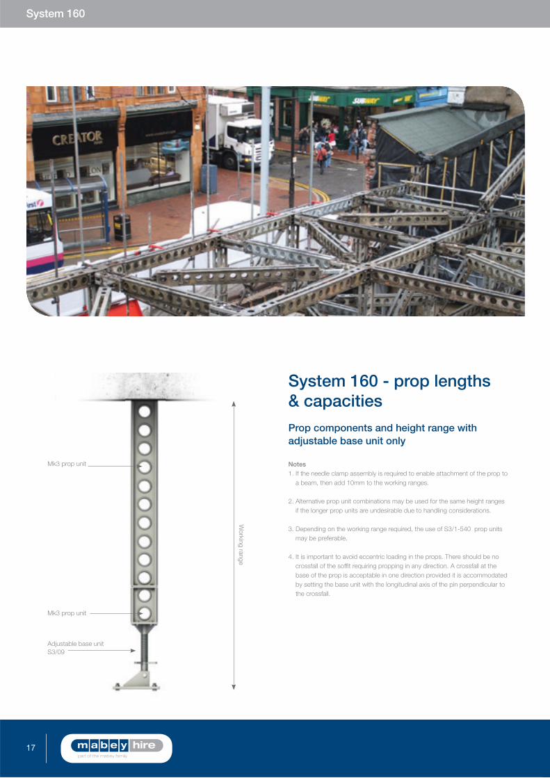
System 160 - prop lengths & capacities
adjustable base unit only
Notes1. If the needle clamp assembly is required to enable attachment of the prop to
a beam, then add 10mm to the working ranges.
2. Alternative prop unit combinations may be used for the same height ranges if the longer prop units are undesirable due to handling considerations.
3. Depending on the working range required, the use of S3/1-540 prop units may be preferable.
4. It is important to avoid eccentric loading in the props. There should be no crossfall of the soffi t requiring propping in any direction. A crossfall at the base of the prop is acceptable in one direction provided it is accommodated by setting the base unit with the longitudinal axis of the pin perpendicular to the crossfall.

18England & Wales t: 0845 741 3040 Scotland: t: 0845 841 3040 www.mabeyhire.co.uk
Working range
Adj. base S3/09 (318mm - 767mm)
S3/1-360S3/1-900 S3/1-1800 S31-2700 S3/1-3600 S3/1-4500 S3/22 Bolts Weight
(kg)
767 - 1127 1 1 - - - - - 4 45
1038 - 1487 1 2 - - - - - 8 57
1218 - 1667 1 - 1 - - - - 4 58
1578 - 2027 1 1 1 - - - - 8 71
1938 - 2387 1 2 1 - - - - 12 84
2118 - 2567 1 - - 1 - - - 4 74
2478 - 2927 1 1 - 1 - - - 8 86
2838 - 3287 1 2 - 1 - - - 12 99
3018 - 3467 1 - - - 1 - - 4 96
3378 - 3827 1 1 - - 1 - - 8 109
3738 - 4187 1 2 - - 1 - - 12 121
3918 - 4367 1 - - - - 1 - 4 116
4278 - 4747 1 1 - - - 1 - 8 128
4638 - 5087 1 2 - - - 1 - 12 141
4818 - 5267 1 - - - - - 1 4 135
5178 - 5627 1 1 - - - - 1 8 147
5538 - 5987 1 2 - - - - 1 12 160
5718 - 6167 1 - 1 - - - 1 8 160
6078 - 6527 1 1 1 - - - 1 12 173
6438 - 6887 1 2 1 - - - 1 16 185
6618 - 7067 1 - - 1 - - 1 8 175
6978 - 7427 1 1 - 1 - - 1 12 188
7338 - 7787 1 2 - 1 - - 1 16 200
7518 - 7967 1 - - 2 - 1 - 12 197
7878 - 8327 1 1 - 2 - 1 - 16 209
8238 - 8687 1 2 - 2 - 1 - 20 222

19
System 160
Mk3 Prop unit
318mm minimum767mm maximum
Holding down bolts as required
base unit
Adjustable base unit bolts
directly to the prop unit end
plate, range 318 – 767mm
over end plates.
Code no: S3/09
Weight: 33kg
A range of fi ttings are available from stock allowing
System 160 to be used in the many varied applications
found in today’s demanding construction industry.
End plate
120
240
60
322 405
200
Ø26
Six-way connector
Connects up to 6 prop
units at 90º angles.
Code no: S3/42
Weight: 40kg
Six-way connector insitu
230
230
360
base unit insitu
Fixed head unit
Bolts directly to prop unit end
plate, use S3/10 to connect
to another prop body, S3/10A
provides a fl at end plate with
holes suitable for fi xing to Mk2
prop units or any other surface.
Code no: S3/10 or S3/10a
Weight: 16.7kg
Fixed head unit insituS3/10a end plate
235450
65
250 330
150
90 40
System 160 - fi ttings
Mk3 prop unit
Connects prop units at
90º. Can also be used as
a 360mm prop unit.
Code no: S3/24
Weight: 18.5kg
180
360
90º prop unit connector insitu
Mk3 Prop unit
230

20England & Wales t: 0845 741 3040 Scotland: t: 0845 841 3040 www.mabeyhire.co.uk
Max. Adjustment: 140º
Mk3 pop unit
Scaffold Tube
Bolts directly to the prop end.
Code no: S3/25
Weight: 19.5kg
M24 x 140 long Gr8.8 Bolts Code no: S3/21
Web connector
Use web connectors to connect fi ttings to the web holes in prop
units. Use S3/05 (with S3/21 bolt and Double Web Connector
S3/05B to connect to System 160 prop units. Use S3/05A
(in conjunction with S3/21 bolt) to connect to Mk2 prop units.
Code no: S3/05
Weight: 3.2kg including bolt.
Web connector insitu
Prop unit
90
2 No. half clipsCode no. LIN-S3/43K
4 No. bolts per connectionCode no. S3/22
Scaffold clamp insitu
Provides a swivel connection
between prop end plate and
web fi xings on another unit
(uses S3/05 web connectors).
Code no: S3/40
Weight: 21kg
Web connectorCode no. S3/05
Max. adjustment: 160º Mk3 prop unit
Scaffold clamp
Used in pairs to connect
scaffold tube bracing to props.
Code no: S3/30
Weight: 1kg
Alternative S3/GGC is available.
Header
connector insitu
180
230
250
Header connector
Provides a connection between
prop end plates and header beam
when using prop unit headers.
Code no: S3/55
Weight: 13kg
21
System 160
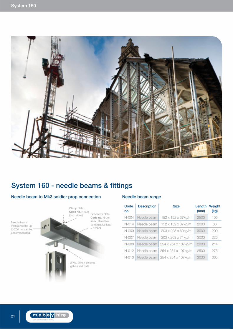
System 160 - needle beams & fi ttings
Needle beam range
Code no.
Description Length (mm)
Weight (kg)
N-004 Needle beam 152 x 152 x 37kg/m 2500 105
N-014 Needle beam 152 x 152 x 37kg/m 2000 86
N-009 Needle beam 203 x 203 x 60kg/m 3000 200
N-007 Needle beam 203 x 203 x 71kg/m 3000 225
N-008 Needle beam 254 x 254 x 107kg/m 2000 214
N-012 Needle beam 254 x 254 x 107kg/m 2500 275
N-010 Needle beam 254 x 254 x 107kg/m 3030 365
Clamp plate Code no. N-003(both sides) Connector plate
Code no. N-001(max. allowable compressive load = 150kN)
2 No. M16 x 60 long galvanised bolts
Needle beam to Mk3 soldier prop connection
Needle beam (Flange widths up to 254mm can be accommodated)

22England & Wales t: 0845 741 3040 Scotland: t: 0845 841 3040 www.mabeyhire.co.uk
Mk3 prop unit
Tilting head Code no. S3/53
Web connectors Code no. S3/05
Lindapter fi xingCode no. LINC152BK,LINC203BK orLINC254BK
Location plate Code no. N-011
Needle beam
Mk3 prop unitHeader beam
Needle beam to header beam connection
100
M16
Ø18
290
350
10
Needle beam clamp assembly
Clamp plate
Code no. N-003
Weight: 1.4kg
Washer
Code no. N-002
Weight: 0.25kg
Connector plate
Code no. N-001
Weight: 3.1kg
Ø18
168
100
12
10 6
75
Ø18

23
System 160
Examples: An N-004 Needle spanning 2.0 subject to a central point loading of 52kN will deflect 1.9mm. A Prop Unit Needle spanning 2.0 subject to a central point loading of 52kN will deflect 2.2mm
Note: The graphs extend to the point where one of the following limits is reached: a) The central point load reaches its maximum safe value. b) The deflection reaches 3.0mm. c) The central point load reaches 200kN.Under controlled design conditions, eg with props of a higher capacity, it may be possible to work above these limits. Please contact us for assistance.
System 160 - properties
0 1 2 3
50
100
130
1.8m Span
2.0m Span
2.3m Span
Deflection (mm)
Poi
nt L
oad
(kN
)
1.5m
Spa
n
1.5m
Spa
n
1.8m Span
2.0m Span
2.3m Span
0 1 2 3
50
100
130
Deflection (mm)
Poi
nt L
oad
(kN
)
0 1 2 3
50
100
Deflection (mm)
Poi
nt L
oad
(kN
)
220
200
150
1.5m
Spa
n
1.8m
Spa
n
2.0m
Spa
n
2.3m S
pan
3.0m Span
1.5m
Spa
n
1.8m
Spa
n2.
0m S
pan
2.3m
Spa
n
3.0m
Spa
n
0 1 2 3
50
100
Deflection (mm)
Poi
nt L
oad
(kN
)
220
200
150
Central point load on 152 x 152 x 37kg/m U.C. needle beam N-004
Central point load on prop unit used as a needle beam
Central point load on 203 x 203 x 60kg/m U.C needle beam N-009
Central point load on 254 x 254 x 107kg/m U.C. needle beam N-008 and N-010
Span (m)
Central point load (kN)
Deflection (mm)

24England & Wales t: 0845 741 3040 Scotland: t: 0845 841 3040 www.mabeyhire.co.uk
A modular shoring system capable of supporting loads of up to
250kN. Components can be used as individual shores or built into
towers and trusses using standard components.
Prop Units
Grillage Beams
Properties
Fittings
Bracing
Mass 25

25
Mass 25 is a purpose designed propping system offering a 250kN
capacity and compact 180mm square section.
Mass 25 includes a comprehensive range of standard bracing
members that can be bolted directly to the flanges of the prop
bodies thus allowing the simple bracing of props and efficient
construction of towers and trusses from standard components.
Mass 25 - prop units
Mass 25
System benefits
250kN vertical load capacity
Flange holes provided for simple
connection of accessories
Compact 180mm x 180mm section can
be manhandled if necessary
Can be built into efficient towers and
trusses from standard components
Range of bracing and accessories
available to ensure flexibility of
design and use

26England & Wales t: 0845 741 3040 Scotland: t: 0845 841 3040 www.mabeyhire.co.uk
Code no. Description Length (mm) Weight (kg)
FP009 Prop unit 90 7.8
FP018 Prop unit 180 9.8
FP036 Prop unit 360 13.7
FP054 Prop unit 540 18.3
FP090 Prop unit 900 26.7
FP1800 Prop unit 1800 47.6
FP2700 Prop unit 2700 69.190mm prop unit
Code no. FP009
90
180
360
540
900
1800
2700
2700mm prop unit
Code no. FP2700
180
60
60
60 60
180
Ø55
6x Ø18End elevation Flange elevation
Y
X X180
30
60 60
60
180
Typical cross section
Y360
Ø18 Holes60 60120120
360
60
30
60
30
60

27
Mass 25
Mass 25 Grillage Beams allow loads to be spread into groups
of props or can provide base spreaders where appropriate.
Standard length 203x203x60kg/m UC grillage beams are
available to allow loads to be shared between props or to
provide load spread at the base of props or towers.
Mass 25 - grillage beams
Code no. Description Length (mm) Weight (kg)
FG001 Grillage beam 900 70
FG003 Grillage beam 2520 183
FG004 Grillage beam 3240 234
210
206
10mm Thick Load Bearing Stiffeners
Cross section
End plate
200
200
Ø22
120
120
Grillage beam - various lengths
360 360
Flange elevation (FG003 & FG004)
60 60120
60
60
Ø18 (Beam Flanges) Ø22 (End Plates)
60 60120

28England & Wales t: 0845 741 3040 Scotland: t: 0845 841 3040 www.mabeyhire.co.uk
Mass 25 - properties Note:1. When used in tension the Safe Working Load is 150kN
for 4no bolts and 210kN for 6no bolts per joint.
2. Limitations of End Fittings: Values may be limited by the type of end fittings used. In the absence of a standard end fitting, the load must be applied through a stiff surface such as a steel plate or uniform concrete surface.
3. Vertical prop values assume that the load is applied concentrically along the centre of the prop (i.e. no eccentricity). Horizontal prop values assume a 25mm eccentricity (vertical and self weight only). More comprehensive charts including values for eccentric loading are available in the technical data sheets.
4. For controlled situations where the loading is predictable, Factor of Safety of 1.7 may be used.
5. All bolt joints require a mimimum of 4 no. bolts.
6. Longer props can be braced to reduce the effective length and improve the capacity. Please refer to the Mass 25 Data Sheet.
7. Further information should be obtained from the product technical data sheets or Mabey Hire engineers.
Section modulus (Nett) 110cm3
Minimum cross sectional area 23.5cm2
Second moment of area 996cm4
Maximum bending moment suitably restrained assuming no point load
20kNm
Maximum shear capacity 175kN
Effective length (m) SWL vert. (kN)
1 340 296
2 340 280
3 340 251
4 325 205
5 236 152
6 172 109
7 129 78
8 101 56
9 80 40
10 65 27
0 1 2 3 4 5 6
0
Effective length (m)
50
100
150
200
250
Saf
e W
orki
ng A
xial
Loa
d w
ith F
.o.S
of 2
.0 (k
N)
300
350
7 8 9 10
Vertical prop (No eccentricity)
Horizontal prop (25mm vertical
eccentricity. Axial & self weight only)

29
Min. 0º
Max. 50º
Mass 25
Mass 25 - fi ttingsAdjustable ends, pivot connectors and base plates are available
as standard items from stock further enhancing the fl exibility of
the Mass 25 range.
Adjustable pivot end
Provides adjustment for both vertical
and raking props. Load restrictions
apply to this item please refer to the
Mass 25 data sheet.
Code no. FF001
Weight: 17kg
Min. 222m
m - M
ax. 422mm
12
180
180
12
4 No. Ø18 holes in each end plate
Min. 183m
m - M
ax. 383mm
180
1106 No. Ø18 holes in each end plate
Bolts directly to prop end
plates. Load restrictions apply
to this item please refer to the
Mass 25 data sheets.
Code no. FF006
Weight: 9.4kg
insitu
Adjustable spherical end
Provides adjustment for vertical
props. The base plate will allow
a 5 degree rotation to cater for
uneven surfaces. Load restrictions
apply to this item please refer to
the Mass 25 data sheets.
Code no. FF002
Weight: 15kg
Min. 0º
Max. 60ºAdjustable
pivot end insitu
Adjustable
spherical end
insitu

30England & Wales t: 0845 741 3040 Scotland: t: 0845 841 3040 www.mabeyhire.co.uk
Base plate -
406x406x20mm
Mass 25 base plates bolt
directly to the prop and are
used to bolt prop units or
structures to a base.
Code no. FF014
Weight: 27.2kg
450
4 No. Ø18
10 No. Ø22
90
450
406
4 No. Ø22
16 No. Ø18
120
120
4 No. Ø22
350
4 No. Ø18250
120
270
220
344244
172
Base plate -
350x250x20mm
The FF013 base plate is an
alternative to FF014 and
is used where the vertical
face of a prop unit is against
another structure.
Code no. FF013
Weight: 14.4kg
Scaffold clamp
Modifi ed half coupler allows
connection of scaffold to
Mass 25 Prop Units.
Code no. FF018
Weight: 0.6kg
Wall plate
10mm thick fl ange can be
set into brickwork to achieve
a 65mm deep bearing shelf.
Code no. FF010
Weight: 19.7kg
Prop unit
Scaffold tube
FF018 Can be used in pairs for
a 90 degree joint.
Scaffold clamp insitu
31
Mass 25
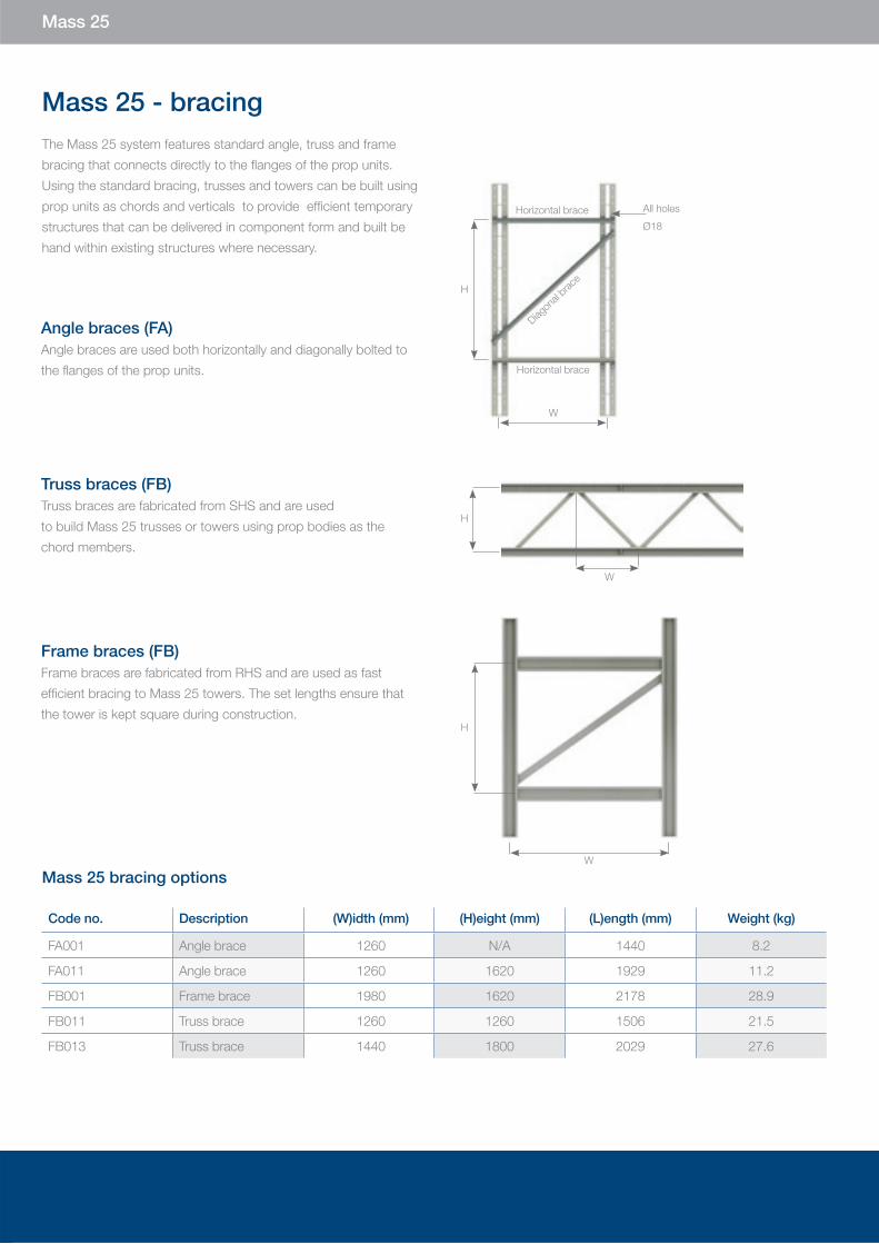
Mass 25 - bracingThe Mass 25 system features standard angle, truss and frame
bracing that connects directly to the flanges of the prop units.
Using the standard bracing, trusses and towers can be built using
prop units as chords and verticals to provide efficient temporary
structures that can be delivered in component form and built be
hand within existing structures where necessary.
Angle braces (FA)Angle braces are used both horizontally and diagonally bolted to
the flanges of the prop units.
Truss braces (FB)Truss braces are fabricated from SHS and are used
to build Mass 25 trusses or towers using prop bodies as the
chord members.
Frame braces (FB)Frame braces are fabricated from RHS and are used as fast
efficient bracing to Mass 25 towers. The set lengths ensure that
the tower is kept square during construction.
W
H
Code no. Description (W)idth (mm) (H)eight (mm) (L)ength (mm) Weight (kg)
FA001 Angle brace 1260 N/A 1440 8.2
FA011 Angle brace 1260 1620 1929 11.2
FB001 Frame brace 1980 1620 2178 28.9
FB011 Truss brace 1260 1260 1506 21.5
FB013 Truss brace 1440 1800 2029 27.6
H
W
Mass 25 bracing options
Horizontal brace
Diagon
al brac
e
Horizontal brace
W
H
All holes
Ø18

32England & Wales t: 0845 741 3040 Scotland: t: 0845 841 3040 www.mabeyhire.co.uk
A modular shoring system designed specifically for the building
refurbishment market. Mass 50 prop units can be used in
simple applications as individual shores or built from standard
components into towers and trusses to form large, complex
façade retention structures.
Prop Units
Grillage Beams
Fittings
Bracing
Mass 50

33
Mass 50
Mass 50 was designed by the Mabey Hire engineering
team specifically for façade retention and structural alterations
in buildings.
Based around 250mmx250mm prop bodies with a 500kN
working load Mass 50 can be braced to both the web flanges
using modular RHS, SHS and angle braces. Stiff, efficient towers
and trusses can be constructed from standard components
ideal for façade retention. Mass 50 can also be used as a 500kN
capacity prop and where necessary in conjunction with the Hymat
hydraulic jacks for pre loading or lifting operations.
Mass 50 - prop unitsSystem benefits
500kN vertical load capacity
Web and flange holes provided for
simple connection of fittings
Compact 250mmx250mm section
can be manhandled if necessary
Designed to be built into efficient trusses
towers and trusses
Range of bracing and fittings available to
ensure flexibility of design and use

34England & Wales t: 0845 741 3040 Scotland: t: 0845 841 3040 www.mabeyhire.co.uk
Code no. Description Length (mm) Weight (kg)
TP010 Prop unit 100 17.0
TP025 Prop unit 250 22.5
TP050 Prop unit 500 32.1
TP100 Prop unit 1000 52.2
TP150 Prop unit 1500 70.6
TP200 Prop unit 2000 90.9
TP250 Prop unit 2500 110.5
TP300 Prop unit 3000 130.3
TP007 Prop shim 3mm 3 1.5
TP008 Prop shim 10mm 10 5.0
TP009 Prop shim 15mm 15 7.0
TPFP10Mass 50/Mass 25
Connector100 17.0
Code no. TP010 Code no. TP300
End elevation Flange elevationTypical cross section
100
250
500
250
75
75
75 75
250
Ø55
6x Ø22
image
Y
Y
X X250
40
75 75
95
250
75
500
Ø22 Holes100 100150150
50
500
1000
2000
3000
2500
1500
75

35
Mass 50
Mass 50 Grillage beams allow loads to be shared between props
or can be used as base spreaders where appropriate, and are
fabricated from 254mmx254mmx107kg/m UC.
Mass 50 - grillage beams
Code no. Description Length (mm) Weight (kg)
TG001 Grillage beam 2000 253.0
TG002 Grillage beam 3500 432.0
TG003 Grillage beam 5000 610.0
TG004 Grillage beam 1000 122.0
TG020 Flange cover plate 850 24.5
TG028 Flange cover plate 1250 43.4
Cross section
End plate
Various lengths (web elevation)
Flange elevation
500 500
250
250
Ø22
150
150
100 100150
75
75
Ø22
100 100150
259
12mm Thick load bearing stiffeners
267

36England & Wales t: 0845 741 3040 Scotland: t: 0845 841 3040 www.mabeyhire.co.uk
Mass 50 - properties Note:1. When used in tension the Safe Working Load is 230kN for 4no bolts and 350kN for 6no bolts per joint.
2. Limitations of End Fittings: Values may be limited by the type of end fittings used. In the absence of a standard end fitting, the load must be applied through a stiff surface such as a steel plate or uniform concrete surface.
3. Vertical prop values assume that the load is applied concentrically along the centre of the prop (i.e. no eccentricity). Horizontal prop values assume a 25mm eccentricity (vertical and self weight only. More comprehensive charts including values for eccentric loading are available in the technical data sheets.
4. For controlled situations where the loading is predictable, Factor of Safety of 1.7 may be used.
5. All bolt joints require a mimimum of 4 no. bolts.
6. Longer props can be braced to reduce the effective length and improve the capacity. Please refer to the Mass 50 Data Sheet.
7. Further information should be obtained from the product technical data sheets or Mabey Hire engineers.
Section modulus (Nett) 280cm3
Minimum cross sectional area 38.2cm2
Second moment of area 3500cm4
Maximum bending moment suitably restrained assuming no local point load
50kNm
Maximum shear capacity 180kN
Effective length (m) SWL vert. (kN)
0 600 500
1 600 500
2 600 480
3 600 456
4 598 422
5 532 372
6 441 307
7 353 243
8 282 189
9 229 145
10 188 111
0
Effective Length (m)
100
200
300
400
500
Saf
e W
orki
ng A
xial L
oad
with
F.o
.S o
f 2.0
(kN
)
600
700
0 1 2 3 4 5 6 7 8 9 10
Vertical Prop (No eccentricity)
Horizontal Prop (25mm vertical eccentricity.
Axial & Self Weight only)

37
Min. 0º
Max. 75º
Range
201-396mm
Prop unit
Max. 70º
Min. 0º
Mass 50
Mass 50 - fi ttingsAdjustable ends, pivot connectors and base plates are available
as standard items from stock further enhancing the fl exibility of
the Mass 50 range.
Adjustable pivot end
Bolts directly to prop end plates and
fl anges to provide adjustment to
both vertical and raking props. Load
restrictions apply to this item please
refer to the Mass 50 data sheets.
Code no. TF003
Weight: 31kg
Bolts directly to prop units to
provide angled connection to a
maximum of 75 degrees.
Code no. TF002
Weight: 31kg
insitu
Adjustable spherical end
Bolts directly to prop end plates
and provides adjustment for
vertical props. This unit has no
tensile capacity and should not be
used for push pull applications.
The base plate will allow 5
degrees rotation, please refer to
the Mass 50 data sheets.
Code no. TF021
Weight: 26.3kg
Adjustable
pivot end insitu
Adjustable
spherical end
insitu
220
25
220
220
6No. Ø22
4 No. Ø22 holes in bottom plate
Range 299-546m
m
6 No. Ø22holes intop plate
Range 201-396m
m

38England & Wales t: 0845 741 3040 Scotland: t: 0845 841 3040 www.mabeyhire.co.uk
Range200-300mm
Prop unit
Grillage beam
Titan assembley
Titan wedge jack with
adaptor plates for Mass 50,
used when high shear loads
are present.
Code no. TF016
Weight: 44kg
Scaffold clamp
Modifi ed half coupler allows
connection of scaffold to
Mass 50 Prop Units.
Code no. TF018
Weight: 1kg
20
250
4 No. Tapped Ø22 Holes
in each End Plate
250
Prop unit
Scaffold tube TF018 Can be used in pairs for a
90º joint
450
360
350
450
450
100
350
200
Scaffold clamp insitu
Scaffold clamp insitu
Wall, base plates & brackets
Wall plate
Code no. TF010
Weight: 17kg
Wall plate fl ange
Code no. TF011
Weight: 8kg
Wall plate insitu
10mm thick fl ange can
be set into brickwork to
achieve a 65mm deep
bearing shelf.
Gallows bracket
Used to support the self-weight of
Mass 50 equipment. Provided with
22mm dia holes for fi xing to existing
structures.
Code no. TF015
Weight: 23kg
Adjustable pivot end insitu

39
Mass 50
450
500
402 350
350
450
450
350
350
Double base plate
Provided with countersunk holes
for prop bolts to allow use on a
fl at surface without a grout bed.
Code no. TF013
Weight: 41kg
Double base plate insitu
Single base plate
Provided with countersunk holes
for prop bolts to allow use on a
fl at surface without a grout bed.
Code no. TF012
Weight: 39kg
Single base plate insitu
Code no. Description Weight (kg)
TF006Galvanised Plate Washer with 22mm holes for tie bars
1.8
TF017Mass 50 to MAT125transfer plate
24
TF019Double Mass 50 to MAT125 transfer plate
33
TF019A Vertical Wall Plate 3.2
TF024 Pivot End - Fixed 500kN 51.4
TF029Mass 50 to Hymattransfer plate
10
Code no. Application
M20 x 40 Prop fl ange (TP) - Prop fl ange (TP)
M20 x 45
Prop fl ange (TP) - Prop end (TP)Prop fl ange (TP) - Truss brace (TB001/002/003)Prop fl ange (TP) - Truss cleat (TF004)Prop fl ange (TP) - Wallplate (TF010)Prop fl ange/web (TP) - Bracing cleat (TF001/014)Angle bracing (TA) - Bracing cleat (TF001/014)
M20 x 50
Prop fl ange (TP) - Frame brace (TB004/005/006/007)Prop fl ange (TP) - Adjustable end (TF003/TF021)Wallplate (TF010) - Prop end (TP)Wallplate (TF010) - Wallplate angle (TF011)Bracing cleat (TF001/014) - Grillage web (TG)
M20 x 55Prop end (TP) - Prop end (TP)Prop fl ange (TP) - Pivot end (TF002)Double angle (TA) - Cleat or Pack (TF001/014/005)
M20 x 60Prop end (TP) - Grillage fl ange (TG)Prop end (TP) - Adjustable end (TF003/TF021)
WASH20 20mm Flat Washer
M20x65Prop end (TP) to Pivot end (TF002)Prop end (TP) to base plate (TF012/TF013)Grillage fl ange/end (TG) to Grillage fl ange/end (TG)
Bolts Additional Mass 50 fi ttings
40England & Wales t: 0845 741 3040 Scotland: t: 0845 841 3040 www.mabeyhire.co.uk
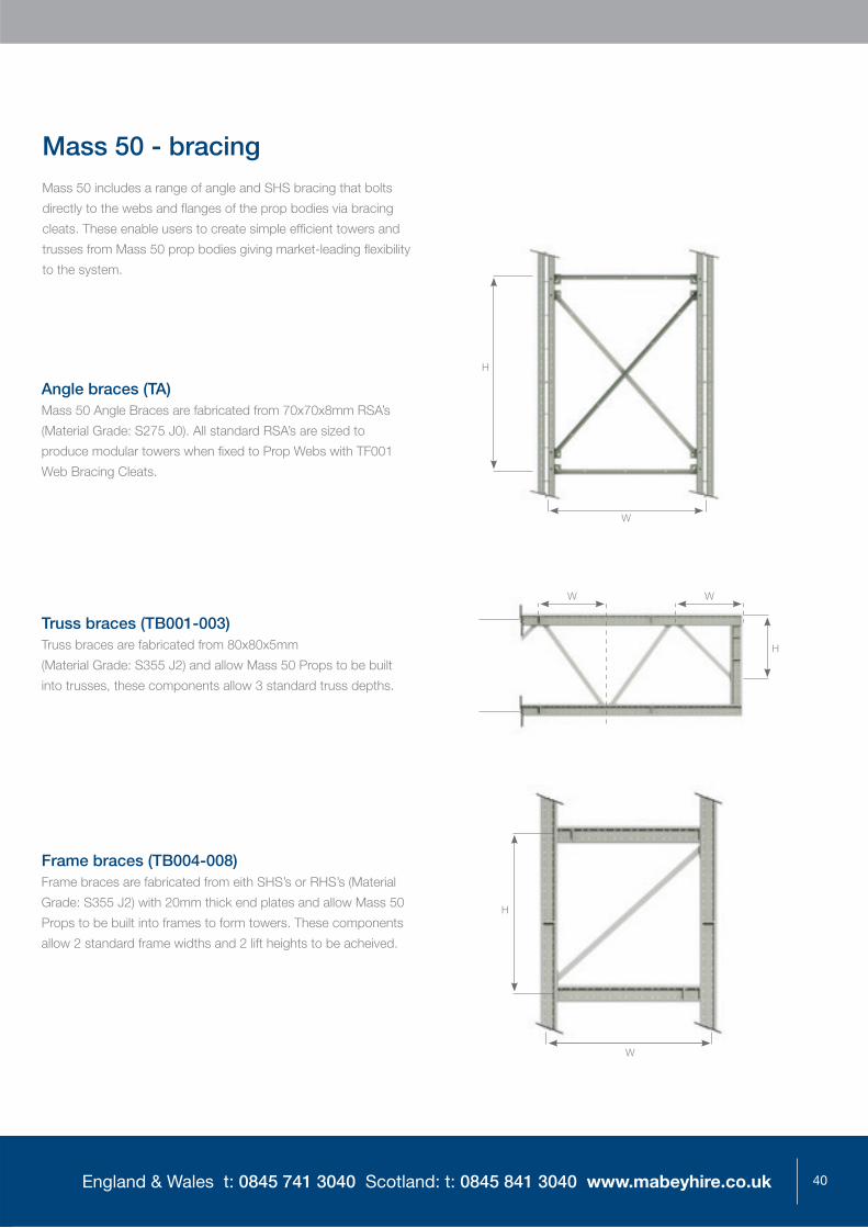
Mass 50 - bracingMass 50 includes a range of angle and SHS bracing that bolts
directly to the webs and flanges of the prop bodies via bracing
cleats. These enable users to create simple efficient towers and
trusses from Mass 50 prop bodies giving market-leading flexibility
to the system.
Angle braces (TA)Mass 50 Angle Braces are fabricated from 70x70x8mm RSA’s
(Material Grade: S275 J0). All standard RSA’s are sized to
produce modular towers when fixed to Prop Webs with TF001
Web Bracing Cleats.
Truss braces (TB001-003)Truss braces are fabricated from 80x80x5mm
(Material Grade: S355 J2) and allow Mass 50 Props to be built
into trusses, these components allow 3 standard truss depths.
Frame braces (TB004-008)Frame braces are fabricated from eith SHS’s or RHS’s (Material
Grade: S355 J2) with 20mm thick end plates and allow Mass 50
Props to be built into frames to form towers. These components
allow 2 standard frame widths and 2 lift heights to be acheived.
W
H
H
W
W
H
W

41
Mass 50
Mass 50 bracing options
Bracing fittings
Truss fixing cleat
Code no. TF004
Weight: 4kg
Angle bracing pack
Code no. TF005
Weight: 0.3kg
Web bacing cleat
Code no. TF001
Weight: 5.5kg
Flange bracing cleat
Code no. TF014
Weight: 7kg
Used in pairs when connecting prop flange to web face.
Used as a packer when braces are battened in pairs back to back.
Connects (TA) angle bracing to prop webs.
Connects (TA) angle bracing to prop flanges.
Code no. Description (W)idth (mm) (H)eight (mm)Component
(L)ength (mm) Weight (kg)
TA001 Side diagonal 2750 3500 4038 34
TA002 Side plan diagonal 2750 2500 3329 28
TA003 Side diagonal 2750 3250 3848 33
TA004 Side diagonal 1500 2500 2492 21
TA005 Side diagonal 1750 3250 3268 28
TA006 Side tie / strut 3000 NA 2846 24
TA007 Side tie / strut 2750 NA 2596 22
TA008 Side tie / strut 1500 NA 1346 11
TA009 Diagonal truss hanger 3500 3000 4228 36
TA010 Diagonal truss hanger 2500 3000 3494 30
TA011 Vertical truss prop NA 2500 2346 20
TA012 Vertical truss prop NA 3500 3346 28
TA013 Side diagonal 1500 2000 2084 17
TA014 Plan diagonal 1500 1500 1729 14
TA015 Side diagonal 2750 2000 3040 25.5
TA016 Side diagonal 2750 1500 2811 24
TA017 Side diagonal 2750 1750 2916 24.4
TA020 Side tie / strut 1750 NA 1596 13.5
TA021 Side tie / strut 2000 NA 1846 15
TA022 Diagonal tie / strut 2000 2500 2790 23.3
TA023 Diagonal tie / strut 2000 2000 2433 20.3
TB001 Truss brace 1500 Truss 1500 1745 33
TB002 Truss brace 2000 Truss 2000 2125 37
TB003 Truss brace 2500 Truss 2500 2546 43
TB004 Frame brace 3250 3500 4213 99
TB005 Frame brace 3250 2500 3571 85
TB006 Frame brace 2500 3500 3725 73
TB007 Frame brace 2500 2500 2879 61
TB010 Frame brace 2750 2250 3019 72
TB011 Knee brace 1250 1250 1571 26
TTB008 H D truss brace 1000 1500 1458 53

42England & Wales t: 0845 741 3040 Scotland: t: 0845 841 3040 www.mabeyhire.co.uk
A high strength robust shoring system offering a capacity
of up to 1250kN per column. Props can be used
individually or built into rigid high strength towers that can
be crane handled where appropriate.
Column Units
Joists
Properties
Fittings
Bracing
Mat 125

43
Mat 125
MAT 125 or “Military Trestling” has been the industry standard for
the support of heavy loads for many years. Mabey Hire’s policy
of continuous improvement has led to the re engineering of the
original concept in modern steels to offer enhanced capacities and
increased flexibility. MAT 125 has a working load of 1250kN per
column and is regularly used in conjunction with the Mabey Hymat
jack system to pre load, strike or lift from the top of the columns.
MAT 125 - column units
3600mm
Column unit
Code no. MT506
Typical cross section
165
273
273
End elevation406Ø22
406
Ø10886 86 86 86
86
86
86
86
76mm
Column stool
Code no. MT511
Code no. Description Length (mm) Weight (kg)
MT256 Column pack 6 7.5
MT041 Column pack 13 15.2
MT042 Column pack 19 22.3
MT043 Column pack 25 29.3
MT044 Column pack 32 36.3
MT045 Column pack 40 50.4
Column pack
Code no. Description Length (mm) Weight (kg)
MT501 Column unit 600 110.2
MT502 Column unit 900 135.1
MT504 Column unit 1200 159.0
MT505 Column unit 2400 288.0
MT506 Column unit 3600 382.0
Column unit
Code no. Description Length (mm) Weight (kg)
MT511 Column stool 76 48.0
MT512 Column stool 114 50.0
MT507 Column stool 152 62.3
MT510 Column stool 190 69.0
MT508 Column stool 229 72.8
MT509 Column stool 305 78.9
Column stool
600mm
Column unit
Code no. MT501
3600
600
900
1200
2400
See table to right for all sizes.
System benefits
Robust high load capacity system
Can be pre fabricated and crane handled
Fully compatible with Hymat hydraulic jacks
Range of standard bracing available
Standard head and base grillage available

44England & Wales t: 0845 741 3040 Scotland: t: 0845 841 3040 www.mabeyhire.co.uk
Standard joists, base and header beams are available as part of the
MAT125 system. Joists and header beams can be used to transfer
loads into columns or foundations.
MAT 125 - joists
Code no. Description Length(mm)
Weight(kg)
MT221 Joist pair assembly 1500 218.2
MT221A Joist pair assembly heavy 1500 271.8
MT227 Joist pair assembly 2100 300.1
MT227A Joist pair assembly heavy 2100 361.5
MT228 Joist pair assembly 2500 363.7
MT228A Joist pair assembly heavy 2500 447.1
MT222 Joist pair assembly 3000 427.3
MT222A Joist pair assembly heavy 3000 516.5
MT229 Joist pair assembly 3600 509.2
MT229A Joist pair assembly heavy 3600 615.4
MT223 Joist pair assembly 4500 636.4
MT223A Joist pair assembly heavy 4500 770.4
MT224 Joist pair assembly 6100 845.6
MT224A Joist pair assembly heavy 6100 1044.6
MT225 Joist pair assembly 7600 1054.7
MT225A Joist pair assembly heavy 7600 1303.5
MT226 Joist pair assembly 9100 1263.8
MT226A Joist pair assembly heavy 9100 1562.4
MT251 Fishplate - 5.5
MT252 Flange cover - 10.0
MT261 Grillage clamp - 3.2
MT262 Grillage clamp Type A - 3.6
MT263 Grillage clamp Type B - 3.6
Base/header beam
Code no. MT610
Weight: 1144kg
End elevation4560
1524 1524
Base/header beam
Code no. MT222
Weight: 427.3kg
End elevation3000
Joist pairs are fabricated from 305x152x65kg/m rolled steel joists. Heavy joist pairs are fabricated from 305x152x80kg/m rolled steel joists.
Code no. Description Length (mm) Weight (kg)
MT610 Base/header beam 4560 1144
MT610 are fabricated from 610x305x238kg/m Universal Beams (Grade 50D).
Code no. Description Length (mm) Weight (kg)
MT281 Base/header beam 800 189
MT281 are fabricated from 356x368x177kg/m Universal Columns (Grade 43C).
Code no. Description Length (mm) Weight (kg)
MT282 Base/header beam 2100 590
MT282 are fabricated from 305x305x240kg/m Universal Columns (Grade 50D).

45
Mat 125
MAT 125 - properties
Note:1. When used in tension the Safe Working is 165kN for 4no bolts and 580kN
for 12no bolts per joint.
2. Limitations of End Fittings: Values may be limited by the type of end fittings used. In the absence of a standard end fitting, the load must be applied through a stiff surface such as a steel plate or grouted surface.
3. Values assume that the load is applied to a vertical prop concentrically along the centre of the prop (ie no eccentricity). More comprehensive charts including values for eccentric loading and horizontal props are available in the technical data sheets.
4. For controlled situations where the loading is predictable, Factor of Safety of 1.7 may be used.
5. All bolt joints require a mimimum of 4 no. bolts.
6. Longer props can be braced to reduce the effective length and improve the capacity. Please refer to the Mat 125 Data Sheet.
7. Further information should be obtained from the product technical data sheets or Mabey Hire engineers.
Section modulus (minimum) 438cm3
Minimum cross sectional area 74.9cm2
Second moment of area (minimum) 5565cm4
0 1 2 3 4 5 60
Effective Length (m)
Saf
e W
orki
ng A
xial
Loa
d w
ith F
.o.S
of 2
.0(k
N)
200
400
600
800
1000
1200
1400
7 8 9 10
1600

46England & Wales t: 0845 741 3040 Scotland: t: 0845 841 3040 www.mabeyhire.co.uk
A range of fi ttings is available for MAT 125 to further enhance the
fl exibility of the system in a variety of uses. A range of hydraulic
jacks for pre loading or lifting uses are available (see pages 56-62)
MAT 125 - fi ttings
Adjustable screw end
Provides adjustment at the base or head
of the column units in either vertical or
raking applications. The unit can be used in
conjunction with our range of hydraulic jacks
(page 56) to preload, strike props or lift and
lower structures.
Code no. MT062
Weight: 150kg
Access bearer
Bolts to column batten plates to
provide support and handrail fi xing
point for a boarded walkway.
Code no. MT601
Weight: 26.9kg
Access bearer insitu
Range 450-780m
m
Adjustable screw end insitu
400 400
Column hinge unit
Provides a fi xed length pivot option
for raking shore applications using
MAT125 column units.
Code no. MT061
Weight: 123.2kg
Column hinge unit insitu
219
406406
37º 37º
37º 37º
Column units

47
Mat 125
MAT 125 - fi ttings (continued)
Bolts to column unit to allow
raking prop fi tting.
Code no. MT172
Weight: 19kg
insitu
Bolt details Connection type
M20 x 50
Bolt, Nut and Washer
Column Web to Column Spacer,
Column Web to 1.5m Strut, Column
Web to Bracing Bracket, Column
Web to Push/Pull Connector,
Column Web to Twin Column
Bracing Bracket, Column Web to
Access Bearer, Bracing Angle to
Bracing Bracket, Bracing Angle to
Plan Bracing Bracket, Joist to Joist
Spacer, Joist to Grillage Clip
M20 x 65
Bolt, Nut and Washer
Column Web to Plan Bracing
Bracket, Column Bracket to Push/
Pull Connector, Column Bracket
to Twin Column Bracing Bracket,
Column Bracket to Access Bearer,
Column Web to Access Corner
Bracket, Joist to Fish Plate, Joist to
Flange Cover
M20 x 70
Bolt, Nut and Washer
Column Cap to Column Cap,
Column Cap to Adjustable Screw
End, Column Cap to Column Hinge
Unit, Column Cap to Joist Pair,
Joist Pair to Column Hinge Unit,
Column Batten to Plan Bracing
Bracket, Column Batten to Access
Corner Bracket
M20 x 100
Bolt, Nut and Washer
Joist Pair to Adjustable Screw end
Bolts application table

48England & Wales t: 0845 741 3040 Scotland: t: 0845 841 3040 www.mabeyhire.co.uk
MAT 125 includes a range of angle bracing that bolts
directly to the prop units via bracing cleats. These enable
users to create simple stable towers and prop lines.
MAT 125 - bracing
A range of angle braces are available to brace the MAT
125 columns at 1500mm or 3000mm centres to form
high load towers or braced column rows.
Plan braces and brackets are available
to brace tower structures.
w2
W1
H
W1
Code no. Description Length (mm) Weight (kg)
MT101 Column spacer 3 1.4
MT102 Column spacer 10 3.6
MT103 Column spacer 133 10
MT104 Column spacer 267 15.4
MT105 Column spacer 406 29.5
Column spacers
Column spacer 267mm
Column spacers bolt directly to the Mat 125
column face to allow the close coupling of
columns for concentrated loads.
Code no. MT104
Weight: 15.4kg

49
Mat 125
Code no. Description Width (W1) (mm) Width (W2) (mm) Height (H) (mm) (L)ength (mm) Weight (kg)
MT191 Horizontal brace 1100 - - 764 6.00
MT192 Diagonal brace 1100 - 1220 1271 9.00
MT193 Diagonal brace 1100 - 914 1040 13.00
MT146 Plan brace 1100 1524 - 1355 11.20
MT156 Plan brace bracket 1100 1524 - - 9.10
MT123 Diagonal brace 1524 - 915 1385 12.70
MT124 Diagonal brace 1524 1524 1220 1568 11.80
MT125 Diagonal brace 1524 - 610 1262 16.90
MT141 Plan brace 1524 1524 - 1568 11.80
MT142 Plan brace 1524 3048 - 2880 40.00
MT152 Plan brace bracket 1524 3048 - - 9.10
MT121 Horizontal brace 1524 - - 1181 11.00
MT187 Diagonal brace 2286 - 900 2083 30.00
MT186 Diagonal brace 2286 - 1220 2203 35.00
MT185 Diagonal brace 2286 - 2134 2745 37.00
MT181 Horizontal brace 2286 - - 1936 26.00
MT184 Diagonal brace 2286 - 2438 2967 40.00
MT144 Plan brace 2286 1524 - 2186 30.00
MT145 Plan brace 2286 3048 - 3220 43.00
MT148 Plan brace 2286 2286 - 2645 35.50
MT154 Plan brace bracket 2286 1524 - - 9.10
MT155 Plan brace bracket 2286 3048 - - 9.10
MT132 Diagonal brace 3048 - 914 2810 37.70
MT133 Diagonal brace 3048 - 1220 2905 36.40
MT134 Diagonal brace 3048 - 2134 3329 46.80
MT135 Diagonal brace 3048 - 2438 3515 49.10
MT143 Plan brace 3048 3048 - 3273 51.80
MT131 Horizontal brace 3048 - - 2699 37.70
MT182 Horizontal brace 4572 - - - 45.00
MT151 Bracing T bracket - - - - 10.50
MT153 Plan brace bracket 45º - - - - 9.10
MAT 125 - bracing
Mat 125

50England & Wales t: 0845 741 3040 Scotland: t: 0845 841 3040 www.mabeyhire.co.uk
A high load shoring system with integrated adjustment and
hydraulic pre load / lifting facility providing a load capacity
of 2400kN per column. Superprop is widely used for the
support and lifting of bridge decks and heavy loads.
Prop Modules
Header Beams
Properties
Fittings
Superprop

51
Superprop
Superprop - prop modulesSuperprop offers high load capacity and speed of erection
due to its unique pinned joints. Each column has a working
load of 2400kN and features adjustable heads and bases
with the facility to add hydraulic jacks for pre loading or lifting
operations. Used extensively for bridge jacking throughout the
UK the Superprop range combines the flexibility of an off the
shelf solution with high load capacities.
Code no. Description Length(mm)
Weight(kg)
SPA002Prop module 3048mm (inc connecting pins)
3048 456.8
SPA003Prop module 1524mm (inc connecting pins)
1524 278.0
SPA004Prop module 762mm (inc connecting pins)
762 198.0
SPA006Prop module 385mm (inc connecting bolts)
385 198.0
SP031Prop module 1000mm (inc connecting bolts)
1000 260.0
Code no. SPA006
Weight: 198kg
Code no. SPA002
Weight: 456.8kg
3048
385
762
1524 3048
End elevation
System benefits
erection of props
maximum flexibility
and header beams

52England & Wales t: 0845 741 3040 Scotland: t: 0845 841 3040 www.mabeyhire.co.uk
The Superprop range includes header beams that feature a
unique full strength pinned splice arrangement. Header beams
connect to the heads and bases of the props to provide load
transfer or spreading arrangements. Superprop header beams
are often used to provide cable or service support during
bridge replacement operations.
Superprop - header beams
Various
Twin header beam assembly
Code no. SPA009
Weight: 1053.6kg
Code no. Description Length (mm) Weight (kg)
SPA008Twin header beam assembly
4000 795.0
SPA009Twin header beam assembly
6000 1053.6
SP021Twin header beam assembly
2000 711.4
Header beams are fabricated from 406x178x67kg/m universal beams (Grade 50C).
Section modulus (gross) 2380cm3
Minimum cross sectional area 171cm2
Second moment of area 48600cm4
Maximum bending moment suitably restrained assuming no local point load
460kNm
Maximum moment of resistance at joint 300kNm
Maximum shear capacity 860kN
End elevation

53
Superprop - bracingSuperprops can be braced using standard bridging panels,
non standard centres are achieved using push pull props or
purpose made angle bracing.
Bracing panelSuperprop Bracing Panels are available in 3m or 1.5m lengths
and space the props at 2050mm centres, bracing panels can
be doubled up to achieve 3600mm centres.
Superprop
Code no. Description Height (mm) Weight (kg)
AB001 Bracing panel 3048mm 1550 267.0
AB016 Bracing panel 1524mm 1550 160.0
AB010 Reinforcing chord 3048mm - 92.0
AB021 Reinforcing chord 1524mm - 57.0
AB057 Chord bolt - 1.3
Bracing panel 3048mm
Code no. AB001
Weight: 267kg

54England & Wales t: 0845 741 3040 Scotland: t: 0845 841 3040 www.mabeyhire.co.uk
Note:1. The superprop system is not designed to be used in tension.
2. Limitations of End Fittings: Values may be limited by the type of end fittings used. In the absence of a standard end fitting, the load must be applied through a stiff surface such as a steel plate or grouted surface.
3. Values assume that the load is applied to a vertical prop concentrically along the centre of the prop (ie no eccentricity). More comprehensive charts including values for eccentric loading and horizontal props are available in the technical data sheets.
4. Longer props can be braced to reduce the effective length and improve the capacity. Please refer to the Superprop Data Sheets.
5. Further information should be obtained from the product technical data sheets or Mabey Hire engineers.
Section modulus 940cm3
Minimum cross sectional area 106cm2
Second moment of area 23600cm4
Superprop - properties
0 1 2 3 4 5 6
Effective Length (m)S
afe
Wor
king
Axi
al L
oad
with
F.O
.S o
f 1.7
(kN
)7 8 9 10
0
500
1000
1500
2000
2500

55
Adjustable head and base units form an essential part of the
Superprop system together with fl at base plates that pin directly
to the Superprop columns units.
Adjustable head assembley
The adjustable head assembly
provides top adjustment on the
module together with the facility
to positon up to 4 hydraulic jacks
giving a maximum of 200Te
hydraulic pre load or lift capacity.
Code no. SPA001
Base unit
Flat base unit pins directly to the
prop module and can be bolted to
the SPA006 385mm prop module.
Code no. SPA005
Adjustable head
assembly insitu
Header beam
Code no. SPA009
MIN
MAX
779
- 11
94m
m
Adjustable base unit
Adjustable base assembly pins
directly to the prop module to provide
adjustment at the base of a prop.
Code no. SPA007
Base unit
Prop module
Superprop - fi ttings
Superprop
Prop module
MIN
MAX
779
- 11
94m
m
Prop module
Connected straight to
the ground OR SPA006.

56England & Wales t: 0845 741 3040 Scotland: t: 0845 841 3040 www.mabeyhire.co.uk
As the UK market leader in heavy shoring, jacking and monitoring
we operate a comprehensive range of hydraulic jacks and
pressurising equipment together with state of the art computer
controlled hydraulic lift and distance monitoring equipment.
General overview
Hymat jacks
Screw ram jacks
Plain ram jacks
Double acting/ hollow ram jacks
Climbing jack system
Specialist monitoring & instrumentation
Hydraulics & Jacking

57
Hydraulics & Jacking
Hydraulics & Jacking - general overviewApplicationMabey Hire offer a comprehensive range of hydraulic jacks,
pressurising equipment and monitoring systems. Many of these
products have been developed in house for use with our high
load propping systems through experience and dialogue with our
clients. The range includes low height and hollow ram jacks and
the specialised Mabey Climbing Jack system used for lifting and
lowering heavy loads through distances in excess of 2m.
Design codesAll Mabey hydraulic cylinders comply with ASME B30.1.
ASME B30.1 is a code recognised and accepted by the
Highways Agency.
TestingAll Mabey hydraulic equipment is subject to a rigorous inspection
and testing regime that is carried out by our experienced in
house hydraulics technicians. The in house procedure exceeds
that required by law and reflects our focus on providing quality
equipment to site.
Our ISO 9001:2008 accredited system includes a fully
documented inspection record for each individually numbered
piece of equipment. Proof load testing can be carried out in house
should this be a requirement for specific uses.
Hydraulic ancillariesMabey Hire offers a comprehensive range of ancillaries to
complete the jacking systems.
Hydraulic pumps
We offer a full range of hydraulic pumps including the manual
hand pump (single acting), electric pump (single/double acting),
standard petrol driven pump (single/double acting) and the
synchronised petrol driven pump which offers either 4 or 6 outlets.
Hoses, manifolds, non return valves, variable relief valves
and pressure guages
We offer a range of thermo plastic hoses from 3m to 15m lengths
together with non return/variable relief valves, both standard or
digital pressure guages from 600 to 10,000 PSI and 2, 4 and
6 way manifolds to allow the construction of the most complex
hydraulic circuits.
Displacement monitoring
The standard method of measuring displacement is by using a
dial test indicator (DTI), we offer either 25mm or 50mm stroke
DTIs with magnetic stands and adjustable arms. The DTI can
be fitted directly to structural steelwork or a suitable steel plate
bonded to a concrete surface and has an accuracy
of 0.01mm.
Mabey Hire offer a specialist jacking service, which can design, plan and operate simple or complex jacking services. Featured is an example of a typical hydraulic design.

58England & Wales t: 0845 741 3040 Scotland: t: 0845 841 3040 www.mabeyhire.co.uk
Hydraulics & Jacking - hymat jacksThe Hymat jack is a lightweight alloy cylinder designed
in house by Mabey engineers specifically for use with
Mabey MAT 125 (see Pages 42-49). It is entirely
compatible both in terms of load capacity and
connection details. The Hymat can also be used in
conjunction with our lighter Mass 50 propping system.
Unlike a conventional screwed ram locking collar the
Hymat has an external collar providing greater stability.
The versatile Hymat cylinder can be used supplied
with a variety of head and baseplates suited to
individual applications, including a spherical head
which allows a 5° rotation.
Code no. HM050 HM100 HM200 HM300
Cylinder capacity (tonnes) 75 75 75 75
Collar capacity (tonnes) 150 150 150 150
Stroke (mm) 55 105 210 300
26.0 30.0 45.0 57.0
Retracted height (mm) 215 265 405 505
Extended height (mm) 270 370 615 805
Outside diameter (mm) 254 254 254 254

59
Hydraulics & Jacking
Hydraulics & Jacking - screw ram jacksWe offer a range of Screwed Ram (SR) Jacks for
general use. All Jacks in this range are single acting,
and incorporate a 5° spherical head.
The screwed ram jacks include a threaded locking
collar to allow load transfer from the hydraulic ram,
providing a mechanical load path.
Code no. SR050 SR100 SR100-50 SR200 SR300 HJ020 HJ050 HJ250 HJ520
Cylinder capacity (tonnes) 50 50 109 189 325 150 50 260 520
Collar capacity (tonnes) 50 50 109 189 325 150 80 260 520
Stroke (mm) 50 100 50 200 200 20 12 45 45
15.0 19.0 25.0 160.0 263.0 26.0 12.0 74.0 186.0
Retracted height (mm) 180 230 137 441 512 115 60 159 192
Extended height (mm) 230 330 187 641 712 135 72 204 237
Outside diameter (mm) 128 128 178 235 310 200 175 275 400
M8 Kingston Bridge-Stobcross Ramp: Vertical and horizontal jacking using Superprop and screw ram jacks.

60England & Wales t: 0845 741 3040 Scotland: t: 0845 841 3040 www.mabeyhire.co.uk
Hydraulics & Jacking - plain ram jacksThe PR Jack series is intended for use in conjunction with the
Mabey Superprop system (see page 50). Jack seating’s are
provided at the prop head to enable the pre-loading, jacking-up
or releasing of the structure to be carried out without the use of
any secondary packing or support.
All Jacks in this range are single acting, incorporating a 5°
spherical head. This Jack range does not incorporate a screw
collar, a separate means of mechanical support
(i.e. Screw Jack / Packing) is recommended.
Aberthaw Power Station: Seal pit doors were shored using braced Superprop shoring (800Te capacity) and pre-loaded using PR hydraulic jacks.
Code no.
Cylinder capacity (tonnes) 10 50 50 50 55
Collar capacity (tonnes) N/A N/A N/A N/A N/A
Stroke (mm)100
(spring return)250
(spring return)250
(spring return)300
(spring return)400
2.8 14.4 13.0 15.4 37.0
Retracted height (mm) 175 420 365 435 540
Extended height (mm) 275 670 615 735 940
Outside diameter (mm) 57 133 130 130 170

61
Hydraulics & Jacking - double acting/hollow ram jacksThe Hollow Ram Jack range is intended for use with a threaded
bar system such as Dywidag. Jacks can be used in conjunction
with Mass 50 proprietary prop units, adopting specially fabricated
baseplates to ensure concentric connection.
The Hollow Rams Jacks are double acting, the hollow plunger
allows for both pull & push forces and enable fast ram retraction.
Hollow Ram Jacks are provided without a locking collar.
A1(M) Burtee Interchange: Abutment bearing shelf replacement using Mabey Universal Trusses and hollow ram jacks incorporating through bars and an underslung beam
Hydraulics & Jacking
Code no. HDA050(Double acting)
HDA060(Double acting)
HR250(Double acting)
HR150(Single acting)
Cylinder capacity (tonnes)
50 89 27 33
Cylinder capacity (tonnes)
25 39 16 N/A
Collar capacity (tonnes) N/A N/A N/A N/A
Stroke (mm) 330 150 250 150
40.0 35.0 32.0 22.0
Retracted height (mm) 521 323 426 330
Extended height (mm) 851 473 680 485
Outside diameter (mm) 127 159 133 114
62England & Wales t: 0845 741 3040 Scotland: t: 0845 841 3040 www.mabeyhire.co.uk
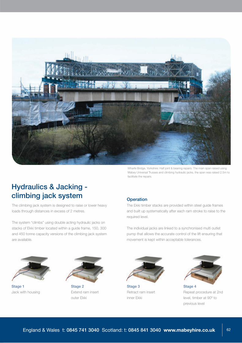
Hydraulics & Jacking - climbing jack systemThe climbing jack system is designed to raise or lower heavy
loads through distances in excess of 2 metres.
The system “climbs” using double acting hydraulic jacks on
stacks of Ekki timber located within a guide frame, 150, 300
and 450 tonne capacity versions of the climbing jack system
are available.
OperationThe Ekki timber stacks are provided within steel guide frames
and built up systematically after each ram stroke to raise to the
required level.
The individual jacks are linked to a synchronised multi outlet
pump that allows the accurate control of the lift ensuring that
movement is kept within acceptable tolerances.
Stage 1
Jack with housing
Stage 2
Extend ram insert
outer Ekki
Stage 3
Retract ram insert
inner Ekki
Stage 4
Repeat procedure at 2nd
level, timber at 90º to
previous level
Wharfe Bridge, Yorkshire: Half joint & bearing repairs: The main span raised using Mabey Universal Trusses and climbing hydraulic jacks, the span was raised 2.5m to facilitate the repairs.

63
Hydraulics & Jacking - specialist monitoring & instrumentationMabey Hire Instrumentation specialises in Structural Monitoring.
Using the unique combination of our experienced engineering and
site teams together with specialist instrumentation and software
engineers and the latest equipment Mabey Hire Instrumentation
offers cost effective practical solutions for the monitoring of all
forms of structure.
We have a wide ranging experience in monitoring solutions where
appropriate combining Geotechnic and Geodetic monitoring
techniques to provide detailed, practical information to engineers
accessible through an internet connection with SMS alerts should
client set limitations be breached.
Where appropriate monitoring systems can be linked to
automated hydraulic jacking equipment from within our range
that will act on information received and correct load in jacks
and position of structures. Mabey Hire provides a unique
“one stop shop” for clients removing potentially difficult
interfaces between specialisms.
Hydraulics & Jacking
An example of a total station layout adopted on a previous project.

64England & Wales t: 0845 741 3040 Scotland: t: 0845 841 3040 www.mabeyhire.co.uk
Structural monitoring
Mabey Hire instrumentation specialise in the application of
monitoring to structures throughout the built environment.
Using Geotechnic and Geodetic techniques cost effective
solutions are provided across a wide range of requirements.
Installations are provided to measure the effect of works being
carried out on or adjacent to existing structures in the short to
medium term. Long term or permanent monitoring equipment
can be provided to structures where concern over condition is
an issue or where long term deterioration is evident and clear
information is required to determine the effect on the structure.
Geodetic monitoring systems measure georeferenced
displacements or movements in one, two or three dimensions.
Using Total Stations and Digital lasers the instruments continually
sight pre fixed targets on structures to record accurate positional
information that can be collected locally by interrogating the
instrument or centrally via a web interface. This technology can
be applied to short or long term use and can be accurate to
+/- 1.5mm.
Applications include:
Bridge movement monitoring
Building movement monitoring
Tunnel monitoring
Ground movement monitoring
Accurate movement monitoring allows engineers to assess the
effect of work on or adjacent to structures enhancing site safety
and allowing early reaction to unexpected effects minimising the
risk of damage to structures and the likelihood of the resultant
third party claims.
Geotechnic monitoring systems measure non-georeferenced
displacements or movements and related environmental effects
or conditions. These techniques accurately measure the
performance and position of structural elements to provide
information whilst under normal working conditions or during
works periods.
Mabey Hire’s long history and experience in civil and structural
engineering allows us to quickly understand requirements and
work with clients to produce tailored, cost effective solutions.
Geotechnic monitoring techniques can be employed to measure
inclination, strain, fatigue, vibration, deflection and crack
movement in short, medium or permanent applications.
Information can be collected locally with hand held devices or
fed to a web site where it can be analysed and presented in a
format to suit the client’s needs.
Applications include:
Bearing Replacement
Half joint monitoring
Load testing
Stress monitoring
Structural health monitoring
Web view of collected data.

65
We want your experience with Mabey Hire to be the
best that it can be and we encourage and welcome your
feedback and suggestions. Please drop us an email at
[email protected] if you have any comments
about our products or services.
Ordering from Mabey Hire We aim to provide immediate response to your requirements,
although advance orders do assist us in providing you with
the best possible service
Please give as full a site address as possible and
a site telephone number if available
Please quote an order number
Working with Mabey Hire

66England & Wales t: 0845 741 3040 Scotland: t: 0845 841 3040 www.mabeyhire.co.uk
DeliveriesUnloading the delivery vehicle is the responsibility of the
customer. Please ensure you have a suitable lifting appliance
available for off-loading
We are happy to assist with the arrangement of special
vehicles e.g. lorry loaders, articulated lorries or low loaders to
deliver the equipment at extra cost
Should you require delivery on a lorry loader, you need to be
aware that there is a Code of Practice for the Safe use of Lorry
Loaders (BS 7121 Part 4 1997) under which you are required
to establish a Safe System of Work
Using our equipmentUse the equipment as set out in our user guides or as
advised in writing by our engineering department
As loss charges can mount up, be it through theft or
otherwise, it is in your interest to look after the equipment
we have supplied
Off-hiringThe equipment is considered to be on hire until you inform
us of the date that it is available for collection, or the date
you return it to our depot
We undertake to collect the equipment within 14 days of the
off-hire date, during this period it is your responsibility
If you are leaving site, please note that we require at least 7
days’ notice to arrange the transport, and we also require you
to be on site to ensure there is a safe system of work in place
for the loading operation
Should we arrive on site to find there is not a safe means of
collecting the equipment, we reserve the right not to proceed
with the collection and to charge you for the wasted journey
Please advise the depot what is to be collected, especially if
it is not all the equipment on site and obtain from them an
“off-hire number” for your records
CollectionsReloading the collection vehicle is the responsibility of the
customer. Please ensure you have a suitable lifting appliance
available for loading
Should you request a lorry loader, you need to be aware that
there is a Code of Practice for the Safe use of Lorry Loaders
(BS 7121 Part 4 1997) under which you are required to
establish a Safe System of Work
ReturnsWhen returning equipment on your own transport, please
ensure that the equipment is counted at the depot and the
amounts entered on the “checking-in-return” form, a copy of
which should be taken by your driver for your own records
Loss / damageLoss and damage cannot be assessed at the time of
return and will be advised on the Goods Inwards Note
sent to your invoice address
Small outstanding amounts of equipment will be assumed
lost to prevent ongoing hire charges
Large outstanding amounts will continue on hire unless
the depot is notified
Where high damage charges are anticipated, you will be
informed by telephone so that you can inspect the goods
in our yard within 7 days
Please direct all queries related to checking-in-returns and
Goods Inwards note to the issuing depot as soon after
receipt as possible

67
The Mabey Hire Propping and Jacking range is a diverse
collection of hire solutions amenable to a variety of project
types. As well as providing the equipment our engineers and
installation teams often work closely with clients to produce
safe, cost-effective solutions for propping and
jacking requirements of all sizes.
Mat-125 trestling Superprop System 160 soldiers
Mabey Hire is more than just your average plant hire company,
we have unrivalled experience, knowledge and product ranges
allowing us to help clients tackle multiple sectors of the industry
safely and effectively.
In our literature we have split our extensive product range into
group solutions to help guide our clients to the right product,
while ensuring they are aware of all the options available to them.
This format has been replicated on our website to facilitate ease
of use and for every product the relevant technical data sheet
or user guide is downloadable straight from the page.

68England & Wales t: 0845 741 3040 Scotland: t: 0845 841 3040 www.mabeyhire.co.uk
Mabey Hire provides a complete range of site access
equipment as well as both temporary and permanent steel
bridging systems to facilitate ease of access which not only
meets, but surpasses all modern safety standards whilst still
allowing rapid, economical installation.
Temporary bridging
Introduced to help increase safety standards for both the
public and workforces in traffi c management schemes
BarrierGuard 800 is approved by the Highways
Agency and the Scottish Roads Authority.
The BarrierGuard 800 system is adaptable for use
on both straight and curved sections of roadway.
The system includes BarrierGuard lengths
and ramped ends.
Road barriers
Trench crossing units Quick bridging
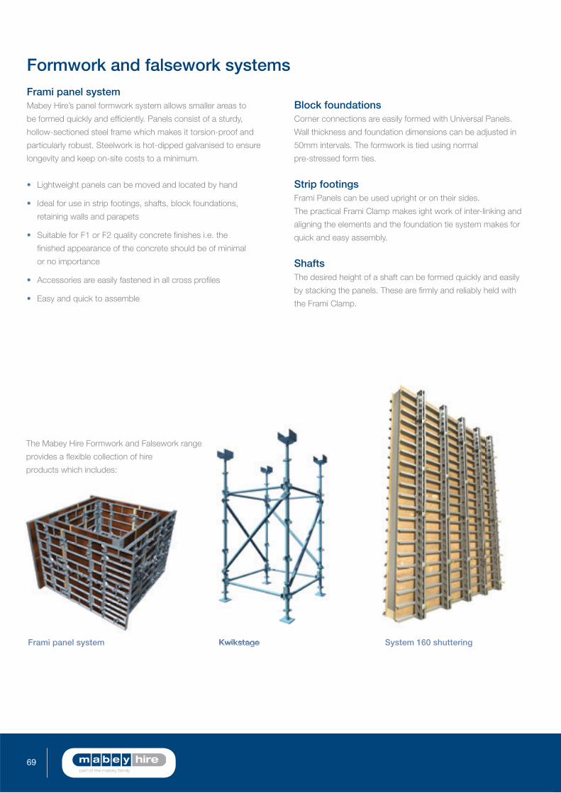
69
Formwork and falsework systems Frami panel systemMabey Hire’s panel formwork system allows smaller areas to
be formed quickly and effi ciently. Panels consist of a sturdy,
hollow-sectioned steel frame which makes it torsion-proof and
particularly robust. Steelwork is hot-dipped galvanised to ensure
longevity and keep on-site costs to a minimum.
Lightweight panels can be moved and located by hand
Ideal for use in strip footings, shafts, block foundations,
retaining walls and parapets
Suitable for F1 or F2 quality concrete fi nishes i.e. the
fi nished appearance of the concrete should be of minimal
or no importance
Accessories are easily fastened in all cross profi les
Easy and quick to assemble
Block foundationsCorner connections are easily formed with Universal Panels.
Wall thickness and foundation dimensions can be adjusted in
50mm intervals. The formwork is tied using normal
pre-stressed form ties.
Strip footingsFrami Panels can be used upright or on their sides.
The practical Frami Clamp makes ight work of inter-linking and
aligning the elements and the foundation tie system makes for
quick and easy assembly.
ShaftsThe desired height of a shaft can be formed quickly and easily
by stacking the panels. These are fi rmly and reliably held with
the Frami Clamp.
Frami panel system Kwikstage System 160 shuttering
The Mabey Hire Formwork and Falsework range
provides a fl exible collection of hire
products which includes:

70England & Wales t: 0845 741 3040 Scotland: t: 0845 841 3040 www.mabeyhire.co.uk
Mabey Hire ContractsMabey Hire Contracts extends the level of service offered to
Mabey Hire clients by providing full subcontract design, supply
and installation packages managed by experienced, specialist in
house engineers and site teams.
From our base near Wigan we offer bridging, falsework, heavy
shoring, façade retention and vehicular restraint systems providing
safe, cost effective temporary works solutions.
Through Mabey Hire Contracts we aim to work hand in hand with
our clients from feasibility through the tender process to contract
and completion providing tailored innovative solutions that
regularly contribute to the success of a tender.
By providing a complete turnkey solution for temporary works
requirements we have established ourselves as a market leader
in the UK, we are able to reduce our clients commercial and
practical risks giving cost certainty and total peace of mind.

Head OfficeScout HillRavensthorpeDewsburyWest YorkshireWF13 3EJt: (01924) 460601f: (01924) 457932

![Camelspace Propping[1]](https://static.fdocuments.net/doc/165x107/577cc5d61a28aba7119d3df3/camelspace-propping1.jpg)