Proposal for optical test requirements of TP2 and TP3 for...
15
Your Imagination, Our Innovation Confidential Proposal for optical test requirements of TP2 and TP3 for 1000Base-RH IEEE 802.3bv interim meeting in Pittsburgh Volker Goetzfried May 19th 2015
Transcript of Proposal for optical test requirements of TP2 and TP3 for...
Your Imagination, Our Innovation
Confidential
Proposal for optical test requirements
of TP2 and TP3 for 1000Base-RH IEEE 802.3bv interim meeting in Pittsburgh
Volker Goetzfried
May 19th 2015
Your Imagination, Our Innovation
Confidential
Subject
• This presentation shows a proposal of test requirements for all optical parameters defined for TP2 and TP3
• Existing standards like 802.3 Ethernet 1000Base-xx were taken as a reference
• Statements (clauses) in this presentation may refer to a table [xxx] indicating the reference to min/max values which are going to be specified in the standard
IEEE 802.3bv interim meeting in Pittsburgh – Test methodologies for TP2 & TP3
Page 2
Your Imagination, Our Innovation
Confidential
IEEE 802.3bv interim meeting in Pittsburgh – Test methodologies for TP2 & TP3
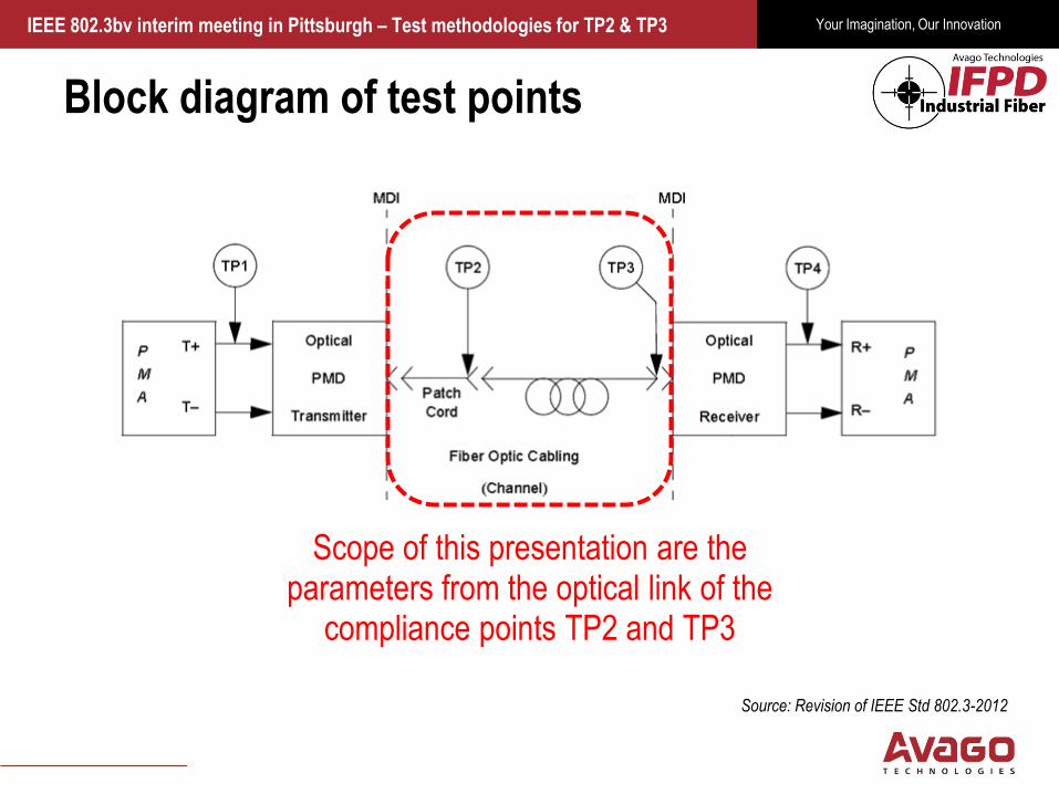
Block diagram of test points
Source: Revision of IEEE Std 802.3-2012
Scope of this presentation are the parameters from the optical link of the
compliance points TP2 and TP3

Your Imagination, Our Innovation
Confidential
Specified parameters
IEEE 802.3bv interim meeting in Pittsburgh – Test methodologies for TP2 & TP3
Page 4
TP2 Parameters Parameter Name Unit Symbol Center Wavelength nm λc Spectral Bandwidth nm Δλ Average Launch Optical Power dBm LOP Average Launch Power of OFF Transmitter dBm LOP,off Extinction Ratio dB ER Modal Power Distribution norm MPD Optical Rise Time (10%/90%) ns tR Optical Fall Time (90%/10%) ns tF Transmitter Random Jitter ps RMS jR Harmonic Distortion 2nd order dBc HD2 Harmonic Distortion 3rd order dBc HD3 Relative Intensity Noise dB/Hz RIN
TP3 Parameters Average Receiving Input Power dBm Pin Average Receiving Input Power for Off State dBm Pin,off Average Receiving Input Power for Wakeup dBm Pin,wakeup

Your Imagination, Our Innovation
Confidential
Optical measurement requirements
• All optical measurements at TP2 shall be made with a short fiber < 1m length. • All optical measurements for the receiver shall be done at
TP3 which is defined to be at the end of a long fiber (min. 15m length).
• The fiber shall be a plastic optical fiber with an NA of 0,5 compliant to [tbd]
IEEE 802.3bv interim meeting in Pittsburgh – Test methodologies for TP2 & TP3
Page 5

Your Imagination, Our Innovation
Confidential
Transmitter measurements at TP2
• All timing parameters need to be acquired with an OEC (optical-to-electrical converter) and an oscilloscope having
at least 3 x FS MHz bandwidth. • The used OEC shall exhibit a constant gain over the whole
bandwidth beginning from DC in order to detect all TP2 parameters specified in table [xxx].
• All electrical parameters from the frequency domain need to be measured with a spectrum analyzer having at least 4 x FS MHz bandwidth.
IEEE 802.3bv interim meeting in Pittsburgh – Test methodologies for TP2 & TP3
Page 6
Fs – Symbol rate of System -> 312,5 / 324 MHz
Your Imagination, Our Innovation
Confidential
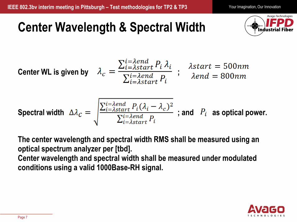
Center Wavelength & Spectral Width
Center WL is given by ;
Spectral width ; and as optical power.
The center wavelength and spectral width RMS shall be measured using an optical spectrum analyzer per [tbd]. Center wavelength and spectral width shall be measured under modulated conditions using a valid 1000Base-RH signal.
IEEE 802.3bv interim meeting in Pittsburgh – Test methodologies for TP2 & TP3
Page 7
Your Imagination, Our Innovation
Confidential
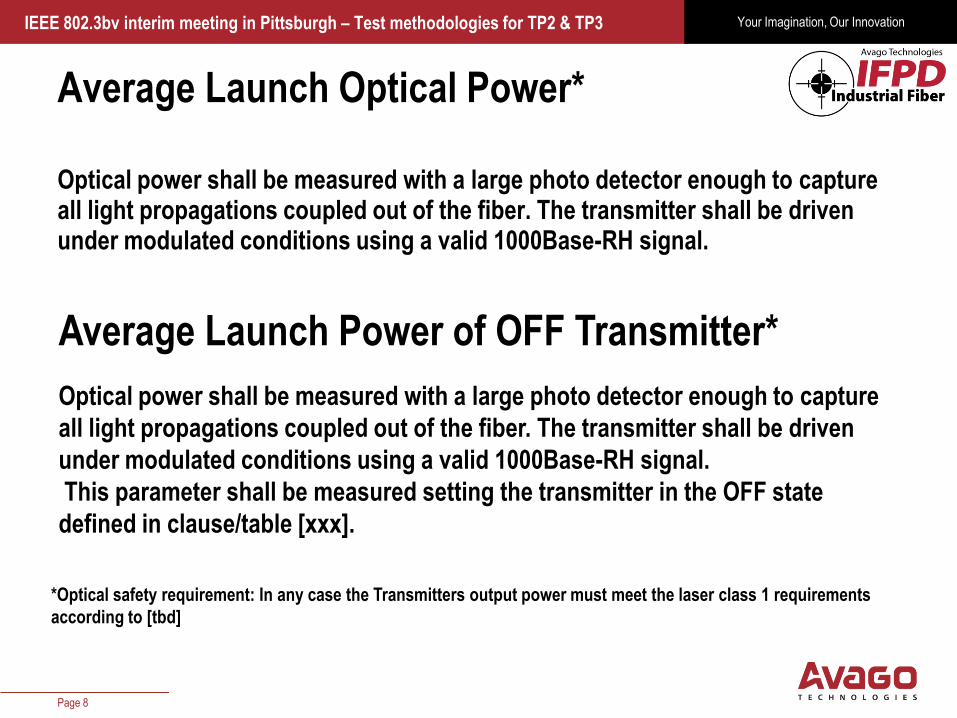
Average Launch Optical Power*
Optical power shall be measured with a large photo detector enough to capture all light propagations coupled out of the fiber. The transmitter shall be driven under modulated conditions using a valid 1000Base-RH signal.
IEEE 802.3bv interim meeting in Pittsburgh – Test methodologies for TP2 & TP3
Page 8
Average Launch Power of OFF Transmitter*
Optical power shall be measured with a large photo detector enough to capture
all light propagations coupled out of the fiber. The transmitter shall be driven
under modulated conditions using a valid 1000Base-RH signal.
This parameter shall be measured setting the transmitter in the OFF state
defined in clause/table [xxx].
*Optical safety requirement: In any case the Transmitters output power must meet the laser class 1 requirements
according to [tbd]

Your Imagination, Our Innovation
Confidential
Extinction Ratio (ER)
Extinction ratio (ER) shall be calculated by measuring the maximum output power P1 and the minimum output P0 which refers to a PAM0 and PAM15 level from a modulation point of view. It is defined as ; in dB In order to avoid any bandwidth limitation effect of the transmitter, a reduced modulation frequency of Fs/10 MHz shall be used comprising of a squarewave binary signal.
-> IEEE802.3 specifies in clause 38.6.3 an ER according to IEC 61280-2-2 -> This is the measurement according to a
pre-defined mask which can be folded/neglected
IEEE 802.3bv interim meeting in Pittsburgh – Test methodologies for TP2 & TP3
Page 9

Your Imagination, Our Innovation
Confidential
Optical Rise/Fall Times
The optical response time specifications are based on unfiltered waveforms. The rise/fall times shall be measured as transition time between 10%/90% and 90%/10% of the maximum amplitude utilizing a square wave PAM-2 signal at Fs/3 MHz.
IEEE 802.3bv interim meeting in Pittsburgh – Test methodologies for TP2 & TP3
Page 10
Random Jitter (jR)
Random jitter shall be measured as RMS value at a bit error rate (BER) of 10-12 The used pattern shall be a square wave PAM-2 signal at Fs/3 MHz. Moreover, an unjittered reference clock signal shall be used as trigger source.
Your Imagination, Our Innovation
Confidential
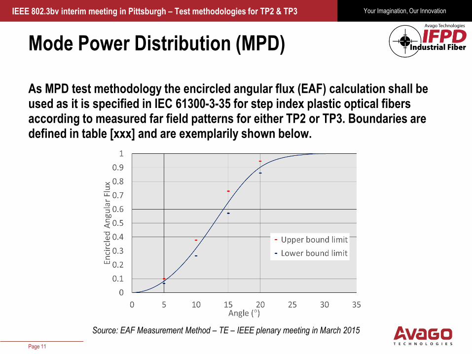
Mode Power Distribution (MPD)
As MPD test methodology the encircled angular flux (EAF) calculation shall be used as it is specified in IEC 61300-3-35 for step index plastic optical fibers according to measured far field patterns for either TP2 or TP3. Boundaries are defined in table [xxx] and are exemplarily shown below.
IEEE 802.3bv interim meeting in Pittsburgh – Test methodologies for TP2 & TP3
Page 11
An Example of Launching Template for Insertion Loss Measurement
7
Source: EAF Measurement Method – TE – IEEE plenary meeting in March 2015

Your Imagination, Our Innovation
Confidential
Harmonic Distortions (HD)
Harmonic distortions 2nd and 3rd order shall be measured using an electrical spectrum analyzer. A single tone represented by a sinusoid with a frequency of Fs/10 MHz shall be applied to the transmitters input. The following is defined for HD2 and HD3: (dBc) Where HD is the magnitude of harmonic distortion k is the order A is the magnitude at frequency F1 is the fundamental frequency
IEEE 802.3bv interim meeting in Pittsburgh – Test methodologies for TP2 & TP3
Page 12

Your Imagination, Our Innovation
Confidential
Relative Intensity Noise (RIN)
This procedure describes a component test which may not be appropriate for a system level test depending on the implementation. A DC signal shall be used to drive the transmitter at its operating point. The following equation is used to evaluate RIN: (dB/Hz) Where RIN is the raltive intensity noise, PN is the electrical noise power in Watts with modulatin off, BW is the low-pass bandwidth of apparatus – high-pass bandwidth of apparatus due to DC blocking capacitor, Ioe is the photocurrent of the OEC
R is the effective load impedance of the OEC
G is the Gain in dB of any amplifier in the noise measurement path
IEEE 802.3bv interim meeting in Pittsburgh – Test methodologies for TP2 & TP3
Page 13
Your Imagination, Our Innovation
Confidential
Average Receiving Input Power (Pin)
Pin defines a minimum optical input power at TP3 where a stable communication is guaranteed for a 1000Base RH link. Sensitivity boundaries are defined under table [xxx].
IEEE 802.3bv interim meeting in Pittsburgh – Test methodologies for TP2 & TP3
Page 14
Average Receiving Input Power for Off and
Wakeup states
Table [xxx] defines a maximum optical input power for a receiver to get into the OFF state for reduced power consumption. Additionally, a minimum optical input power for a receiver is defined to wakeup from OFF state.
Receiver measurements at TP3
Receiver measurements cannot be taken with a standalone PMD component but only together with the PCS and PMA sublayers.

Your Imagination, Our Innovation
Confidential
Questions?
Thank you
IEEE 802.3bv interim meeting in Pittsburgh – Test methodologies for TP2 & TP3
Page 15