Propeller Pump Series ALLPRO PPR and PGE/PGF · PDF filePropeller Pump Series ALLPRO PPR and...
12
Propeller Pump Series ALLPRO PPR and PGE/PGF ® 1 GB/02.09 - Ident-Nr. 488 020 Utilization Main fields of application Performance data Pump series Design ? ? k k PGE/PGF PPR Delivery flow Q up to11,500 m /h up to 50,000 m /h Delivery head H up to 8,5 m up to 12 m Discharge pressure p up to 6 bar up to 6 bar Liquid temperature t up to 200 °C up to 200 °C Delivery branch nominal width Dn 200-700 200-1.200 3 3 d d Pumps for other specifications upon request. The specified operation limits are maximum values. Actual values may be lower in individual cases depending on technical variations. Refer to the respective order documentation for binding values. Inlet pressure plus maximum delivery head may not exceed the permissible discharge pressure. Designed to circulate or accelerate chemically aggressive or non-aggressive liquids; clear liquids or liquids containing solids; hot or cold liquids. - Used in wastewater and clarification engineering as recirculation pumps to return nitrate-laden wastewater or activated sludge from nitrification basins into denitrification basins. Also used in wastewater and clarification engineering to circulate or accelerate other liquids appropriate for propeller pumps. - Used in the chemical industry/process engineering as acceleration pumps in reactor closed loops and as circulation pumps in acid baths or crystallization systems. - Employed as circulation pumps in desalination plants for production of drinking water and salt extraction. - In the cellulose industry as acceleration and mixing pumps. - As circulation pumps in evaporation plants (such as for REA wastewater or acid processing) and in concentration systems. - In the food industry, such as circulation pump in bottle rinsing machines. - Cooling water supply for drive turbines on ships. - Biogas plants. The PPR series utilizes a pump casing made from non- castable materials. The PGE/PGF series is used for cast materials. Single-stage propeller pump with dry installation. The cast or welded pump casing is in the form of a elbow pipe. Depending on the required delivery head, the propeller is equipped with three or more blades.
Transcript of Propeller Pump Series ALLPRO PPR and PGE/PGF · PDF filePropeller Pump Series ALLPRO PPR and...

Propeller PumpSeries ALLPRO PPR and PGE/PGF
®
1GB/02.09 - Ident-Nr. 488 020
Utilization
Main fields of application
Performance data
Pump series
Design
�
�
�
�
�
�
PGE/PGF PPRDelivery flow Q up to 11,500 m /h up to 50,000 m /hDelivery head H up to 8,5 m up to 12 mDischargepressure p up to 6 bar up to 6 bar
Liquid temperature t up to 200 °C up to 200 °CDelivery branchnominal width Dn 200-700 200-1.200
3 3
d
d
Pumps for other specifications upon request.
The specified operation limits are maximum values. Actualvalues may be lower in individual cases depending ontechnical variations. Refer to the respective orderdocumentation for binding values.
Inlet pressure plus maximum delivery head may not exceedthe permissible discharge pressure.
Designed to circulate or accelerate chemicallyaggressive or non-aggressive liquids; clear liquids orliquids containing solids; hot or cold liquids.
- Used in wastewater and clarification engineering asrecirculation pumps to return nitrate-laden wastewateror activated sludge from nitrification basins intodenitrification basins. Also used in wastewater andclarification engineering to circulate or accelerate otherliquids appropriate for propeller pumps.
- Used in the chemical industry/process engineering asacceleration pumps in reactor closed loops and ascirculation pumps in acid baths or crystallizationsystems.
- Employed as circulation pumps in desalination plantsfor production of drinking water and salt extraction.
- In the cellulose industry as acceleration and mixingpumps.
- As circulation pumps in evaporation plants (such as forREA wastewater or acid processing) and inconcentration systems.
- In the food industry, such as circulation pump in bottlerinsing machines.
- Cooling water supply for drive turbines on ships.- Biogas plants.
The PPR series utilizes a pump casing made from non-castable materials.The PGE/PGF series is used for cast materials.
Single-stage propeller pump with dry installation.The cast or welded pump casing is in the form of a elbowpipe. Depending on the required delivery head, thepropeller is equipped with three or more blades.

They are three-dimensionally curved, hydraulicallyoptimized, and insensitive to contamination. Speciallydesigned fiber-deflecting blade shapes are available forliquids with fibrous components.The pump casing can be equipped with anexchangeable wear ring or intermediate piece in theimpeller area of the propeller. The pump has a torsion-proof shaft that ensures smooth running up to theoperational limits specified in the individual curves. Thetorsion-proofness and short distance between the pump-side bearing and shaft seal result in high truth of runningfor optimal shaft sealing conditions.The shaft is protected by an exchangeable shaft sleevein the shaft seal region.The pumps are installed horizontally or vertically and arealso capable of pumping in the opposite direction.
A variety of alternatives are available for sealing theshaft, such as gland packing, mechanical seals, orcartridge seals. Refer to pages 4 and 5 for sealingvariations.
The gland packing version of the PPR series is deliveredwith a stationary gland packing as standard equipment.As a result, it is not necessary to empty the system whenexchanging the seal. This variation is available as anoption on the PGE/PGF series.
The shaft bearing is in an bearing bracket in grease-lubricated antifriction bearings . The bearings aredesigned for a service life of at least 25,000 operatinghours.
The pumps are installed horizontally or vertically in aflood-safe area. The following mounting variations areavailable as standard products:PGE/ Pump installed horizontally or vertically directlyPPR in the pipe, without foundation. Depending on the
weight of the motor, the drive may be flangeddirectly onto the bearing bracket via a motorbracket. When higher-output drives are used, thedrive must utilize a V-belt (motor attached to thebearing bracket via a rocker) or universal jointshaft (motor set up separately).
PGF/ Horizontal pump mounting on foundation.PPR Drive power transmitted via directly-coupled motor
or via gear box/V-belt.Other installation/mounting styles available upon request.
With constant-speed electric motors or speed adjustmentthrough gear box/belt drive or pole-changing orfrequency-regulated electric motors. Speed-regulateddrives allow the pump to properly react to alternatingcapacities without efficiency losses.
The pump fulfills the requirements according to EUexplosion-protection directive 94/9/EC (ATEX100a) for devices in device class II, category
2 G. Classification into temperature classes according toEN 13463-1 depends on the temperature of the pumpedliquid. Refer to the proposal or order documentation forthe maximum permissible liquid temperature for therespective temperature classes.
When operating the pump in category 2, suitablemeasures must be provided to prevent impermissiblewarming of the pump surfaces in the event ofdisturbance.
Flansche
Shaft sealing
Bearing and lubrication
Installation and mounting
Drive
Explosion protectionFlanges PGE/PGF: - Cast/stainless steel acc. toDIN EN 1092-1 PN10/21/B1
- Cast ironDIN EN 1092-2 PN10/21/B
Flanges PPR: - Up to size 800DIN EN 1092-1 PN 10/11/B1
- Size 900 DIN 28036 and larger
Note:
Abbreviation
- /
Series
Direction of inlet
(A=axial/R=radial)
Size/Branch nominal width
Hydraulic
(301, 303, 501, 3f, 3f2)
E Gland packing
D Gland packing with
Shaf seal stationary gland
G Mechanical seal
C Cartridge mech. seal
Material design
PPR A 700 301 D W180
�
�
�
�
�
�
PGE: Cast version, inserted into pipePGF: Cast version, installed on foundationPPR: Welded version, inserted into pipe or installed on
foundation
3f and 3f2 available only for PGE/PGF
PGE/PGF up to size 400: Lifetime grease-lubricatedantifriction bearing. Antifriction bearing with regreasingcapability available as an option. PGE/PGF sizes >400 andPPR all sizes: Regreasable antifriction bearing as standard.
2 GB/02.09 - Ident-Nr. 488 020
Material code
� only parts contacting liquid other materials available as special order (WX)�
Series ALLPRO PPR and PGE/PGF®
Denomination Material design �
W180 W181 W182 W183
Series PGE/PGF PPR PGE/PPF PPR PGE/PGF PGE/PGF PPR
Pump casing EN-GJL 250 St 37 1.4408 1.4571 � 1.4517 1.4529 �
Shaft 1.4571 1.4571 1.4462 1.4529
Propeller 1.4408 / 1.4571 1.4408 / 1.4571 1.4517 / 1.4462 1.4529
Bearing bracket EN-GJL 250 St 37 EN-GJL 250 St 37 EN-GJL 250 EN-GJL 250 St 37

3
Series ALLPRO PPR and PGE/PGF®
500 1.000 1.500 Q[USgqm] 5.000 10.000 20.000 50.000 100.000 200.000
500 1.000 1.500 Q[Jgqm] 5.000 10.000 20.000 50.000 100.000 200.000
Note:
Overall performance range per size in consideration of all permissible speeds.Refer to the individual curves for precise performance data.
3f2 hydraulics for wastewater treatment, blade angle up to 18°
Performance graphsValid for = 1 kg/dm and = 1 mm /sρ
3 2ν
Hydraulic: 3f
Hydraulics:301, 303, 501
H [m]
Hydraulic 501
Hydraulic 301
Hydraulic 303
14
10
7
5
2
1
0,5
0,3100 180 500 1.000 2.000 5.000 10.000 20.000 50.000
200
250
300
350
400
500
600
700
800
9001.000
1.200
200
250
300
350
400
500
600
700
800
9001.000
1.200
200
250
300
350
400
500
600
700
800
900
1.0
00
1.2
00
Q[m /h]3
H [m]
10
7
5
2
1
0,5
0,3100 180 500 1.000 2.000 5.000 10.000 20.000 50.000Q[m /h]3
200
250
300
350
400
500
600
700
Hydraulic 3f
GB/02.09 - Ident-Nr. 488 020

4
Assembly PPRBasic version, shaft sealed with gland packing with stationary gland, shaft bearing grease lubricated.
Cartridge-type shaft sealing (single or multiplemechanical seals)
Intermediate piece Shaft
Propeller Pump casing Shaft seal Bearing bracket
Shaft sealed with single mechanical seal
Series ALLPRO PPR and PGE/PGF®
GB/02.09 - Ident-Nr. 488 020

Assembly PGE/PGFBasic version (cast), shaft sealed with gland packing, shaft bearing grease lubricated.
5
Pump casing Shaft
Propeller Shaft seal Bearing bracket
Cartridge-type shaft sealing (single or multiplemechanical seals)
Shaft sealed with gland packing with stationary gland
Wear-ring version
Shaft sealed with single mechanical seal
Series ALLPRO PPR and PGE/PGF®
GB/02.09 - Ident-Nr. 488 020

Main dimensions PPR
6
Dimensions in mm.
DN
h2
a f
l
h1
DN
EN 1092-1/2-PN 10/21/B �
Key acc. toDIN 6885 u
Ø d1
t
Shaft basis fit for
50:
Ø d < 50: k6Ø d
1
1 > m6
Shaft end
n1
m1
n2
w2
r Ø s
w3 w4 w4 w5 w5 w5
w1
� Size 900 and larger DIN 28036
Pump foot for sizes (200 up to 350) (400 up to 600) (700 up to 1000) (1200)
Series ALLPRO PPR and PGE/PGF®
GB/02.09 - Ident-Nr. 488 020
PPR Pump dimensions Foot dimensions Shaft end
DN a f h1 h2 m1 n1 n2 w1 w2 w3 w4 w5 r s d1 l t u
200 200 340 900 190 200 520 470 424 275 355 - - - 75 23 38 58 41 10
250 250 400 970 212 250 565 498 452 306 400 - - - 75 23 50 82 53,5 14
300 300 490 1050 245 301 650 580 534 350 485 - - - 75 23 50 82 53,5 14
350 350 560 1025 265 352 695 620 574 375 520 - - - 85 23 60 105 64 18
400 400 630 1190 300 402 787 680 620 431 - 280 - - 112 28 75 105 79,5 20
500 500 800 1330 355 504 925 780 720 508 - 350 - - 115 34 85 130 90 22
600 600 950 1530 400 606 1037 914 852 533 - 420 - - 77 34 110 165 116 28
700 700 1120 1705 475 707 1180 874 934 676 - - 298 - 143 34 120 165 127 32
800 800 1244 1845 530 813 1335 1135 1035 730 - - 340 - 172 34 130 200 137 32
900 900 1374 1900 560 919 1390 1174 1104 752 - - 360 - 160 41 140 200 148 36
1000 1000 1550 2095 630 1021 1583 1355 1275 877 - - 420 - 163 41 150 200 158 36
1200 1200 1850 2420 740 1225 1825 1580 1500 980 - - - 300 163 41 180 240 190 45

7
Main dimensions PGE/PGFSize 200 and 250
Pump foot
Pump foot
PGF size 300 and larger (PGE without Pump foot)
DN
h2
a f
l
h1
DN
n1
m1
w1 w2
rØ
s1
EN 1092-1/2-PN 10/21/B
Key acc.toDIN 6885
u
Ø d1
t
n2
Shaft end
Dimensions in mm.
Series ALLPRO PPR and PGE/PGF®
GB/02.09 - Ident-Nr. 488 020
PGE/ Pump dimensions Foot dimensions Shaft end
PGF DN a f h1 h2 b e m1 m2 m3 n1 n2 n3 n4 r w1 w2 s1 s2 d1 l t u
200 200 330 725 180 206 - - 512 - - 300 220 - - 42 132 400 24 - 42 110 45 12
250 250 410 825 225 257 - - 590 - - 375 285 - - 45 165 500 24 - 42 110 45 12
300 300 410 855 250 270 125 50 125 - 80 450 325 120 200 62,5 237,5 442,5 22 22 55 110 59 16
350 350 480 875 280 310 125 50 125 - 80 500 375 120 200 62,5 262,5 507,5 24 24 55 110 59 16
400 400 530 835 315 350 150 60 150 - 100 550 400 170 250 75 315 455 24 24 55 110 59 16
500 500 650 1040 355 440 150 60 200 - 100 650 500 170 250 100 375 605 26 26 70 140 74,5 20
600 600 750 1240 425 520 150 70 200 - 120 750 600 200 300 100 400 730 26 26 85 170 90 22
700 700 860 1380 475 600 175 70 250 125 120 850 675 200 300 62,5 475 805 26 26 85 170 90 22
Pump side
Drive side
a f n1
EN 1092-1/2-PN 10/21/B
n2DN
h2
h1
DN
w1 w2
m1
Ø s1
Ø s
2
n3
n4
b
e m3
l
m2
Key acc. toDIN 6885
u
Ø d1
t
Shaft end

8
Propeller pump installed horizontally, motor to the sideon shared base plate, drive via V-belt.
Mounting
Propeller pump with directly-coupled drive motor,horizontally mounted, on shared base plate.
Propeller pump inserted into pipe. Motor on rocker,fastened onto pump bearing bracket (above or below),drive via V-belt.
Propeller pump with directly-coupled drive motorinserted horizontally or vertically in the pipe.
Propeller pump installed horizontally on base plate,motor aligned above bearing bracket, drive via V-belt.
Propeller pump inserted into pipe, motor on separatebase plate, drive via universal joint.
Series ALLPRO PPR and PGE/PGF®
GB/02.09 - Ident-Nr. 488 020

9
Benefits PPR
� High efficiencythrough a flow-optimizedpropeller head.
� Economicalwith high efficiency acrossa wide capacity range.
� Process optimizedthrough a special torsion-proof shaft in conjunctionwith a tolerance-freeadjustable bearing thatensures high truth-of-running and thereforeoptimal conditions for theshaft seal.
� Affordablethanks to exchangeableintermediate piece whenabrasive liquids cause wear.
� Flexiblein the selection of shaft seals (glandpacking, mechanical seal, cartridgeseal) in a variety of designs andmaterials.
� Insensitiveto deformation caused bypipe forces throughoptimized pump designaccording to finite-elementmethod.
� Efficientwith a large-radius elbow casingfor low flow losses and nodisturbing edges in the shaftpassage.
� Versatilethrough optimized adaptationto operating conditions with avariety of propeller types.
Series ALLPRO PPR and PGE/PGF®
GB/02.09 - Ident-Nr. 488 020
10
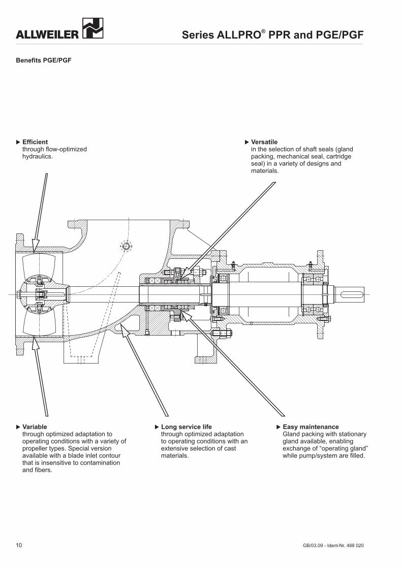
Benefits PGE/PGF
� Versatilein the selection of shaft seals (glandpacking, mechanical seal, cartridgeseal) in a variety of designs andmaterials.
� Efficientthrough flow-optimizedhydraulics.
� Variablethrough optimized adaptation tooperating conditions with a variety ofpropeller types. Special versionavailable with a blade inlet contourthat is insensitive to contaminationand fibers.
� Long service lifethrough optimized adaptationto operating conditions with anextensive selection of castmaterials.
� Easy maintenanceGland packing with stationarygland available, enablingexchange of “operating gland”while pump/system are filled.
Series ALLPRO PPR and PGE/PGF®
GB/03.09 - Ident-Nr. 488 020
11
ALLWEILER delivery range
GB/02.09 - Ident-Nr. 488 020
Centrifugal Pumps
�FeaturesPump capacities acc. to DIN EN 733 or DIN EN 22858. Additional sizes enlarge the EN-performancerange. Series construction acc. to the modularsystem. Single-stage or multistage pumps in block-or inline-design; pumps with magnetic coupling,pumps for heat transfer oil and hot water.
�Pumped liquidsNeutral or aggressive, pure, with solids content orcontaminated, cold or hot, toxic or harmful to theenvironment.
�Performance dataQ up to 2,400 m³/h, H up to 250 m.
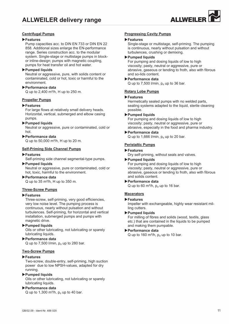
Propeller Pumps
�FeaturesFor large flows at relatively small delivery heads.Horizontal, vertical, submerged and elbow casingpumps.
�Pumped liquidsNeutral or aggressive, pure or contaminated, cold orhot.
�Performance dataQ up to 50,000 m³/h, H up to 20 m.
Self-Priming Side Channel Pumps
�FeaturesSelf-priming side channel segmental-type pumps.
�Pumped liquidsNeutral or aggressive, pure or contaminated, cold orhot, toxic, harmful to the environment.
�Performance dataQ up to 35 m³/h, H up to 350 m.
Three-Screw Pumps
�FeaturesThree-screw, self-priming, very good efficiencies,very low noise level. The pumping process iscontinuous, nearly without pulsation and withoutturbulences. Self-priming, for horizontal and verticalinstallation, submerged pumps and pumps withmagnetic drive.
�Pumped liquidsOils or other lubricating, not lubricating or sparelylubricating liquids.
�Performance dataQ up to 7,500 l/min, pd up to 280 bar.
Two-Screw Pumps
�FeaturesTwo-screw, double-entry, self-priming, high suctionpower due to low NPSH-values, adapted for dryrunning.
�Pumped liquidsOils or other lubricating, not lubricating or sparelylubricating liquids.
�Performance dataQ up to 1,300 m³/h, pd up to 40 bar.
Progressing Cavity Pumps
�FeaturesSingle-stage or multistage, self-priming. The pumpingis continuous, nearly without pulsation and withoutturbulences, crushing or demixing.
�Pumped liquidsFor pumping and dosing liquids of low to highviscosity; pasty, neutral or aggressive, pure orabrasive, gaseous or tending to froth, also with fibrousand so-lids content.
�Performance dataQ up to 7,500 l/min, pd up to 36 bar.
Rotary Lobe Pumps
�FeaturesHermetically sealed pumps with no welded parts,sealing systems adapted to the liquid, sterile cleaningpossible.
�Pumped liquidsFor pumping and dosing liquids of low to highviscosity; pasty, neutral or aggressive, pure orabrasive, especially in the food and pharma industry.
�Performance dataQ up to 1,666 l/min, pd up to 20 bar.
Peristaltic Pumps
�FeaturesDry self-priming, without seals and valves.
�Pumped liquidsFor pumping and dosing liquids of low to highviscosity; pasty, neutral or aggressive, pure orabrasive, gaseous or tending to froth, also with fibrousand solids content.
�Performance dataQ up to 60 m³/h, pd up to 16 bar.
Macerators
�FeaturesImpeller with exchangeable, highly wear resistant mil-ling cutters.
�Pumped liquidsFor milling of fibres and solids (wood, textils, glassetc.) that are contained in the liquids to be pumpedand making them pumpable.
�Performance dataQ up to 160 m³/h, pd up to 10 bar.

GB
/02.
09 –
Iden
t-N
r. 48
8 02
0
A Colfax Business Unit
ALLWEILER AGPostfach 11 4078301 Radolfzell • GermanyTel. +49 (0)7732 86-0Fax +49 (0)7732 86-436E-mail: [email protected]: http://www.allweiler.com
Subject to technical alterations.
ALLWEILER sollutions
Successful in important branches
Decades of experience and branch-specific know-how ensure solutions that are practical and dependable. In additionto individual units with a motor or with a free shaft end, you can get complete systems and customer-specific cast partsfrom ALLWEILER AG. You are not just investing in machines with ALLWEILER AG. You are also profiting from de-cades of know-how about applications and processes in your branch.
You will find pumps and systems by ALLWEILER AG in the following sectors:
� Marine and OffshoreMade of particularly corrosion-resistant, saltwater-proof materials and in accordance with specificstandards (shock testing, national marine,international classifications etc.).
� Power GenerationBlock and twin units for fuel and water injection ingas and steam turbines.For fuel supply, injection and lubricating oil supply inpower plants.
� Water and WastewaterPumps for water treatment (dry substance up to 45%), macerators, which make it possible to pumpliquids that are high in fibre and solids.
� BioenergyMaterials resistant to aggressive intermediate andfinal products. Pumps for every step in the process.
� Process Engineering and Chemical Industry(ATEX-conformity)Shaft bearing, shaft seal and material designs inaccordance with the chemical characteristics of thepumped liquid. Magnetic coupling for hermeticallysealed pumps.
� Oil and GasPumps with a wide viscosity range, high pressureand large capacity.
� Building IndustrySpecial units for oil furnace and lift systems. Oilsubmersible pumps for all types of hydraulicmachines.
� Food and PharmaceuticalStainless steel pumps with CIP and SIP design,EHEDG and FDA certified. Especially for the carefulpumping and dosing of even sticky, pasty andsoids-rich liquids.
� Machine ToolDesigned for large capacity or a high dischargepressure; resistant to contaminants and foreignmaters. Especially for cooling lubricant supply.
� Pulp and PaperPumps with extremely high availability (24 hours;365 days) and many sizes, starting with smalldosing pumps and ranging to large kaolin feedingpumps.
� Heat TransferIn supply circuits, circulating systems and heatingcircuits for pumping of hot water and heat transferoil up to 207 °C and 450 °C.