Proline Promass 83 FOUNDATION Fieldbus, Device …H Literature/Manuals/menu/docs/IOMs/Flow... ·...
200
BA066D/06/en/12.06 71035083 Valid as of version: V 2.00.XX (Device software) Description of Device Functions Proline Promass 83 FOUNDATION Fieldbus Coriolis Mass Flow Measuring System 9 0000 0001 0002 0003 0004 0005 000 AAA A 1000 1001 1002 1003 1004 1005 100 BAA B 2000 2001 2002 2003 2004 2005 200 CAA C 3000 3001 3002 3003 3004 3005 300 DAA D 4000 4001 4002 4003 4004 4005 400 EAA E 5000 5001 5002 5003 5004 500 FAA F 4200 5200 4201 5201 4202 5202 4203 5203 4204 4205 420 520 2400 2401 2402 2403 2404 2405 240 CCA 2200 2201 2202 2203 2204 2205 220 CBA 0200 0201 0202 0203 0204 0205 020 0000 0001 0002 0003 0004 0005 000 AAA A 1000 1001 1002 1003 1004 1005 100 BAA B 2000 2001 2002 2003 2004 2005 200 CAA C 3000 3001 3002 3003 3004 3005 300 DAA D 4000 4001 4002 4003 4004 4005 400 EAA E 5000 5001 5002 5003 5004 500 FAA F 4200 5200 4201 5201 4202 5202 4203 5203 4204 4205 420 520 2400 2401 2402 2403 2404 2405 240 CCA 2200 2201 2202 2203 2204 2205 220 CBA 0200 0201 0202 0203 0204 0205 020 1000 1001 10 100 BAA B 2000 2001 20 200 CAA C 3000 3001 30 300 DAA D 4000 4001 40 400 EAA E 5000 5001 50 500 FAA F 4200 5200 4201 5201 4 5 420 520 2400 2401 24 240 CCA 2200 2201 2 220 CBA 0200 0201 0 020
Transcript of Proline Promass 83 FOUNDATION Fieldbus, Device …H Literature/Manuals/menu/docs/IOMs/Flow... ·...

BA066D/06/en/12.06
71035083
Valid as of version:
V 2.00.XX (Device software)
Description of Device Functions
Proline Promass 83
FOUNDATION Fieldbus
Coriolis Mass Flow Measuring System
90000 0001 0002 0003 0004 0005000AAAA
1000 1001 1002 1003 1004 1005100BAAB
2000 2001 2002 2003 2004 2005200CAAC
3000 3001 3002 3003 3004 3005300DAAD
4000 4001 4002 4003 4004 4005400EAAE
5000 5001 5002 5003 5004500FAAF
4200
5200
4201
5201
4202
5202
4203
5203
4204 4205420
520
2400 2401 2402 2403 2404 2405240CCA
2200 2201 2202 2203 2204 2205220CBA
0200 0201 0202 0203 0204 0205020
0000 0001 0002 0003 0004 0005000AAAA
1000 1001 1002 1003 1004 1005100BAAB
2000 2001 2002 2003 2004 2005200CAAC
3000 3001 3002 3003 3004 3005300DAAD
4000 4001 4002 4003 4004 4005400EAAE
5000 5001 5002 5003 5004500FAAF
4200
5200
4201
5201
4202
5202
4203
5203
4204 4205420
520
2400 2401 2402 2403 2404 2405240CCA
2200 2201 2202 2203 2204 2205220CBA
0200 0201 0202 0203 0204 0205020
1000 1001 10100BAAB
2000 2001 20200CAAC
3000 3001 30300DAAD
4000 4001 40400EAAE
5000 5001 50500FAAF
4200
5200
4201
5201
4
5
420
520
2400 2401 24240CCA
2200 2201 2220CBA
0200 0201 0020

Device Functions Proline Promass 83 FOUNDATION Fieldbus
2 Endress+Hauser
Registered trademarks
FOUNDATION™ Fieldbus
Registered trademark of Fieldbus FOUNDATION, Austin, USA
S-DAT®, T-DAT™, F-CHIP®, ToF Tool - Fieldtool® Package, Fieldcheck®, Applicator®
Pending or registered trademarks of Endress+Hauser Flowtec AG, Reinach, CH
Operation Proline Promass 83 FOUNDATION Fieldbus
- with local operation: see page 3
- with FOUNDATION Fieldbus: see page 103

Device Functions Proline Promass 83 FOUNDATION Fieldbus Table of contents for local operation
Endress+Hauser 3
Table of contents for local operation
1 Notes on using this manual . . . . . . . . . . . . 5
1.1 Using the table of contents to locate
a function description . . . . . . . . . . . . . . . . . . . . . . . 5
1.2 Using the graphic of the function matrix to locate
a function description . . . . . . . . . . . . . . . . . . . . . . . 5
1.3 Using the index of the function matrix to locate
a function description . . . . . . . . . . . . . . . . . . . . . . . 5
2 Function matrix . . . . . . . . . . . . . . . . . . . . . . . . 6
2.1 General layout of the function matrix . . . . . . . . . . . 6
2.1.1 Blocks (A, B, C, etc.) . . . . . . . . . . . . . . . . . . 6
2.1.2 Groups (AAA, AEA, CAA, etc.) . . . . . . . . . . 6
2.1.3 Function groups (000, 020, 060, etc.) . . . . . 6
2.1.4 Functions (0000, 0001, 0002, etc.) . . . . . . . 6
2.1.5 Codes identifying cells . . . . . . . . . . . . . . . . . 7
2.2 Function matrix Proline Promass 83 . . . . . . . . . . . . 8
3 Block MEASURED VARIABLES . . . . . . . . . 9
3.1 Group MEASURING VALUES . . . . . . . . . . . . . . . . 10
3.1.1 Function group MAIN VALUES . . . . . . . . . 10
3.1.2 Function group ADDITIONAL VALUES . . 11
3.2 Group SYSTEM UNITS . . . . . . . . . . . . . . . . . . . . . 14
3.2.1 Function group CONFIGURATION . . . . . . 14
3.2.2 Function group
ADDITIONAL CONFIGURATION . . . . . . . 17
4 Block QUICK SETUP . . . . . . . . . . . . . . . . . . 19
4.1 Quick Setup "Commissioning" . . . . . . . . . . . . . . . . 20
4.2 Quick Setup "Gas Measurement" . . . . . . . . . . . . . . 21
5 Block USER INTERFACE . . . . . . . . . . . . . . 22
5.1 Group CONTROL . . . . . . . . . . . . . . . . . . . . . . . . . 23
5.1.1 Function group BASIC CONFIGURATION 23
5.1.2 Function group UNLOCKING/LOCKING . 24
5.1.3 Function group OPERATION . . . . . . . . . . . 26
5.2 Group MAIN LINE . . . . . . . . . . . . . . . . . . . . . . . . 27
5.2.1 Function group CONFIGURATION . . . . . . 27
5.2.2 Function group MULTIPLEX . . . . . . . . . . . 29
5.3 Group ADDITION LINE . . . . . . . . . . . . . . . . . . . . 31
5.3.1 Function group CONFIGURATION . . . . . . 31
5.3.2 Function group MULTIPLEX . . . . . . . . . . . 34
5.4 Group INFORMATION LINE . . . . . . . . . . . . . . . . 37
5.4.1 Function group CONFIGURATION . . . . . . 37
5.4.2 Function group MULTIPLEX . . . . . . . . . . . 40
6 Block TOTALIZER . . . . . . . . . . . . . . . . . . . . . 43
6.1 Group TOTALIZERS (1 to 3) . . . . . . . . . . . . . . . . . 44
6.1.1 Function group CONFIGURATION . . . . . . 44
6.1.2 Function group OPERATION . . . . . . . . . . . 46
6.2 Group HANDLING TOTALIZER . . . . . . . . . . . . . . 47
7 Block BASIC FUNCTION . . . . . . . . . . . . . 48
7.1 Group FOUNDATION FIELDBUS . . . . . . . . . . . . . 49
7.1.1 Function group CONFIGURATION . . . . . . 49
7.1.2 Function group FUNCTION BLOCKS . . . . 50
7.1.3 Function group INFORMATION . . . . . . . . 51
7.2 Group PROCESS PARAMETER . . . . . . . . . . . . . . . 52
7.2.1 Function group CONFIGURATION . . . . . . 52
7.2.2 Function group EPD PARAMETER . . . . . . . 54
7.2.3 Function group REFERENCE PARAMETER 55
7.2.4 Function group ADJUSTMENT . . . . . . . . . 57
7.2.5 Function group PRESSURE CORRECTION 59
7.3 Group SYSTEM PARAMETER . . . . . . . . . . . . . . . . 60
7.3.1 Function group CONFIGURATION . . . . . . 60
7.4 Group SENSOR DATA . . . . . . . . . . . . . . . . . . . . . . 61
7.4.1 Function group CONFIGURATION . . . . . . 61
7.4.2 Function group FLOW COEFFICIENT . . . . 62
7.4.3 Function group DENSITY COEFFICIENT . . 63
7.4.4 Function group
ADDITIONAL COEFFICIENT . . . . . . . . . . 64
8 Block SPECIAL FUNCTION . . . . . . . . . . 65
8.1 Group DENSITY FUNCTIONS . . . . . . . . . . . . . . . . 66
8.1.1 Function group CONFIGURATION . . . . . . 66
8.2 Group ADVANCED DIAGNOSTICS . . . . . . . . . . . 72
8.2.1 Function group CONFIGURATION . . . . . . 72
8.2.2 Function group ACQUISITION . . . . . . . . . 73
8.2.3 Function group MASS FLOW . . . . . . . . . . . 74
8.2.4 Function group DENSITY . . . . . . . . . . . . . . 75
8.2.5 Function group REFERENCE DENSITY . . . 76
8.2.6 Function group TEMPERATURE . . . . . . . . 77
8.2.7 Function group TUBE DAMPING . . . . . . . 78
8.2.8 Function group
ELECTRODYNAMIC SENSORS . . . . . . . . . 79
8.2.9 Function group OPERATING
FREQUENCY FLUCTUATION . . . . . . . . . . 80
8.2.10 Function group TUBE
DAMPING FLUCTUATION . . . . . . . . . . . . 81
9 Block SUPERVISION . . . . . . . . . . . . . . . . . 83
9.1 Group SYSTEM . . . . . . . . . . . . . . . . . . . . . . . . . . . 84
9.1.1 Function group CONFIGURATION . . . . . . 84
9.1.2 Function group OPERATION . . . . . . . . . . . 85
9.2 Group VERSION INFO . . . . . . . . . . . . . . . . . . . . . 87
9.2.1 Function group DEVICE . . . . . . . . . . . . . . 87
9.2.2 Function group SENSOR . . . . . . . . . . . . . . 87
9.2.3 Function group AMPLIFIER . . . . . . . . . . . . 88
9.2.4 Function group F-CHIP . . . . . . . . . . . . . . . 88
9.2.5 Function group I/O MODULE . . . . . . . . . . 89

Table of contents for local operation Device Functions Proline Promass 83 FOUNDATION Fieldbus
4 Endress+Hauser
10 Factory settings . . . . . . . . . . . . . . . . . . . . . . . 90
10.1 SI units (not for USA and Canada) . . . . . . . . . . . . . 90
10.1.1 Low flow cut off, full scale value,
pulse value . . . . . . . . . . . . . . . . . . . . . . . . 90
10.1.2 Language . . . . . . . . . . . . . . . . . . . . . . . . 90
10.1.3 Density, length, temperature . . . . . . . . . . 91
10.2 US units (only for USA and Canada) . . . . . . . . . . . 91
10.2.1 Low flow cut off, full scale value,
pulse value . . . . . . . . . . . . . . . . . . . . . . . . 91
10.2.2 Language, density, length, temperature . . . 91
11 Index Function matrix . . . . . . . . . . . . . . . . 93
12 Index local operation . . . . . . . . . . . . . . . . . 97
Operation with FOUNDATION Fieldbus . 103

Device Functions Proline Promass 83 FOUNDATION Fieldbus 1 Notes on using this manual
Endress+Hauser 5
1 Notes on using this manualThere are various ways of locating the description of a function of your choice in the manual:
1.1 Using the table of contents to locate a function
description
The designations of all the cells in the function matrix are listed in the table of contents. You can
use these unambiguous designations (such as MEASURED VARIABLES, USER INTERFACE,
TOTALIZER, etc.) to choose whichever functions are applicable to a particular set of conditions.
The page references show you exactly where to find the detailed descriptions of the functions in
question. The table of contents is on page 3.
1.2 Using the graphic of the function matrix to locate a function description
This step-by-step, top-down approach starts with the blocks, the highest level, and factory down
through the matrix to the description of the function you need:
1. All available blocks and their corresponding subgroups are shown on page 8. Select the block
(or the group within the block) which you need for your application and use the page reference
to locate the information corresponding to the next level.
2. The page in question contains a graphic showing of the block with all its subordinate groups,
function groups and functions. Select the function which you need for your application and use
the page reference to locate the detailed function description.
1.3 Using the index of the function matrix to locate a
function description
Each "cell" in the function matrix (blocks, groups, function groups, functions) has a unique identifier
in the form of a code consisting of one or three letters or a three- or four-digit number. The code
identifying a selected "cell" appears at the top right on the local display.
Example:
A0004750
The function matrix index lists the codes for all the available "cells" in alphabetic and consecutive
order, complete with the page references for the corresponding functions. The index to the function
matrix is on page 93.

2 Function matrix Device Functions Proline Promass 83 FOUNDATION Fieldbus
6 Endress+Hauser
2 Function matrix
2.1 General layout of the function matrix
The function matrix consists of four levels:
Blocks → Groups → Function groups → Functions
A0000961
2.1.1 Blocks (A, B, C, etc.)
The blocks are the highest-level grouping of the operation options for the device. The blocks include,
for example: MEASURED VARIABLES, QUICK SETUP, USER INTERFACE, TOTALIZER, etc.
2.1.2 Groups (AAA, AEA, CAA, etc.)
A block consists of one or more groups. Each group represents a more detailed selection of the
operation options in the higher-order block. The groups in the "USER INTERFACE" block, for
example, include: CONTROL, MAIN LINE, ADDITION LINE, etc.
2.1.3 Function groups (000, 020, 060, etc.)
A group consists of one or more function groups. Each function group represents a more detailed
selection of the operation options in the higher-order group. The function groups in the CONTROL
group, for example, include: BASIC CONFIGURATION, UN-/LOCKING, OPERATION, etc.
2.1.4 Functions (0000, 0001, 0002, etc.)
Each function group consists of one or more functions. The functions are used to operate and
parameterize the device. Numerical values can be entered or parameters selected and saved.
The functions in the BASIC CONFIGURATION function group include LANGUAGE, DISPLAY
DAMPING, CONTRAST LCD, etc.
The procedure for changing the language of the user interface, for example, is as follows:
1. Select the USER INTERFACE block
2. Select the CONTROL group
3. Select the BASIC CONFIGURATION function group
4. Select the LANGUAGE function (this is where the language can be selected).
…
…
…
…
…
…
…
…
0001
2001
0401
2021
2201
0002
2002
0402
2022
2202
0003
2003
0403
2023
2203
0009
2009
0409
2029
2209
0429
2049
2069
0421
2041
0422
2042
0423
2043
20632061 2062
0000
2000
0400
2020
2200
0420
2040
2060
000
200
040
202
220
042
204
206
AAA
BAA
ACA
CAA
CBA
D, E, …
A
B
C

Device Functions Proline Promass 83 FOUNDATION Fieldbus 2 Function matrix
Endress+Hauser 7
2.1.5 Codes identifying cells
Each cell (block, group, function group and function) in the function matrix has an individual,
unique code.
Blocks:
The code is a letter (A, B, C, etc.)
Groups:
The code consists of three letters (AAA, ABA, BAA, etc.).
The first letter matches the block code (i.e. each group in block A has a code starting with an "A",
in other words A _ _; the codes of the groups in block B start with a "B", in other words B_ _ , and
so on). The other two letters are for identifying the group within the respective block.
Function groups:
The code consists of three digits (000, 001, 100, etc.)
Functions:
The code consists of four digits (0000, 0001, 0201, etc.).
The first three digits are the same as the code for the function group. The last digit in the code is a
counter for the functions in the function group, incrementing from 0 to 9 (e.g. function 0005 is the
sixth function in group 000).
A0001251
Block Group Function group Functions
2000 2001 2002200CAAC

2 Function matrix Device Functions Proline Promass 83 FOUNDATION Fieldbus
8 Endress+Hauser
2.2 Function matrix Proline Promass 83
BLOCKS GROUPSFUNCTION
GROUPS
MEASURED VARIABLES A → MEASURING VALUES AAA → page 10
( → Page 9) SYSTEM UNITS ACA → page 14
↓ SPECIAL UNITS AEA → page 14
QUICK SETUP B → Commissioning and application setups → page 83
( → Page 9)
↓USER INTERFACE C → CONTROL CAA → page 23
( → Page 22) MAIN LINE CCA → page 27
↓ ADDITION LINE CEA → page 31
INFORMATION LINE CGA → page 37
TOTALIZER D → TOTALIZERS (1 to 3)DAA,
-B, -C→ page 44
( → Page 43) HANDLING TOTALIZER DJA → page 47
↓
BASIC FUNCTION G → FOUNDATION FIELDBUS GGA → page 49
( → Page 48) PROCESS PARAMETER GIA → page 52
↓ SYSTEM PARAMETER GLA → page 60
SENSOR DATA GNA → page 61
SPECIAL FUNCTION H → DENSITY FUNCTIONS HAA → page 66
( → Page 65) ADVANCED DIAGNOSTICS HEA → page 72
↓
SUPERVISION J → SYSTEM JAA → page 84
( → Page 83) VERSION INFO JCA → page 87

Device Functions Proline Promass 83 FOUNDATION Fieldbus 3 Block MEASURED VARIABLES
Endress+Hauser 9
3 Block MEASURED VARIABLES
Fu
ncti
on
s
CO
R.
CA
RR
.V.F
L
(00
29
) P
.1
3
% C
AR
R.
VO
L. FL.
(00
28
) P
.1
2
CA
RR
.
VO
L.F
LO
W
(00
27)
P.1
2
% C
AR
R.
MA
SS F
L
(00
26
) P
.1
2
TE
MP
ER
AT
UR
E
(00
08
) P
.1
0
CA
RR
.
MA
SS F
LO
W
(00
25
) P
.1
2
° B
RIX
(00
36
) P
.1
3
UN
IT
CO
R. V
OLU
ME
(04
05
) P
.1
6
RE
FE
RE
NC
E
DE
NSIT
Y
(00
06
) P.1
0
CO
R.
TA
RG
.V.F
L.
(00
24
) P.1
2
° B
ALLIN
G
(00
35
) P.1
3
UN
IT
CO
R.V
OL.F
L.
(04
04
) P.1
6
UN
IT
PR
ESSU
RE
(0
42
6)
P.18
DE
NSIT
Y
(00
05
) P
.1
0
% T
AR
G.
VO
L. FL.
(00
23
) P
.1
1
° P
LA
TO
(00
34
) P
.1
3
UN
IT V
OLU
ME
(04
03
) P
.1
5
UN
IT
LE
NG
TH
(04
24
) P
.1
8
CO
R.
VO
LU
ME
FLO
W
(00
04
) P
.1
0
TA
RG
.
VO
L.F
LO
W
(00
22
) P
.1
1
° A
PI
(00
33
) P
.1
3
UN
IT
VO
L. FLO
W
(04
02
) P
.1
5
UN
IT
TE
MP
ER
AT
UR
E
(04
22
) P
.1
7
VO
LU
ME
FLO
W
(00
01
) P
.1
0
% T
AR
G.
MA
SS F
L.
(00
21
) P
.1
1
° B
AU
ME
(00
31
) P
.1
3
UN
IT
MA
SS (
04
01
)
P.14
UN
IT
RE
F.
DE
NSIT
Y
(04
21
) P
.1
7
⇒ ⇒ ⇒ ⇒ ⇒
MA
SS F
LO
W
(00
00
) P
.1
0
TA
RG
.
MA
SS F
LO
W
(00
20
) P
.1
1
%-B
LA
CK
LIQ
UO
R
(00
30
) P
.1
3
UN
IT
MA
SS F
LO
W
(04
00
) P
.1
4
UN
IT D
EN
SIT
Y
(04
20
) P
.1
7
⇒ ⇒ ⇒ ⇒
Fun
cti
on
gro
up
s
MA
IN V
ALU
ES
(00
0)
P.1
0
AD
DIT
ION
AL
VA
LU
ES
(00
2)
P.1
1
CO
NFIG
UR
AT
ION
(04
0)
P.1
4
⇓ ⇑
AD
D.
CO
NFIG
UR
AT
ION
(04
2)
P.1
7
⇒ ⇒
Gro
up
s
ME
ASU
RIN
G
VA
LU
ES
(AA
A)
P.
10
⇓ ⇑
SY
ST
EM
UN
ITS
(AC
A)
P.
14
⇒
Blo
ck
ME
ASU
RE
D
VA
RIA
BLE
S
(A)

3 Block MEASURED VARIABLES Device Functions Proline Promass 83 FOUNDATION Fieldbus
10 Endress+Hauser
3.1 Group MEASURING VALUES
3.1.1 Function group MAIN VALUES
MEASURED
VARIABLESA ⇒ MEASURING VALUES AAA ⇒ MAIN VALUES 000
Function descriptionMEASURED VARIABLES → MEASURING VALUES → MAIN VALUES
! Note!
• The engineering units of all the measured variables shown here can be set in the SYSTEM UNITS group.
• If the fluid in the pipe flows backwards, a negative sign prefixes the flow reading on the display.
MASS FLOW
(0000)
The currently measured mass flow appears on the display.
Display:
5-digit floating-point number, including unit and sign
(e.g. 462.87 kg/h; –731.63 lb/min; etc.)
VOLUME FLOW
(0001)
The calculated volume flow appears on the display. The volume flow is derived from
the measured mass flow and the measured density of the fluid.
Display:
5-digit floating-point number, including unit and sign
(e.g. . 5.5445 dm3/min; 1.4359 m3/h; –731.63 gal/d; etc.)
CORRECTED VOLUME
FLOW (0004)
The calculated corrected volume flow appears on the display. The calculated
corrected volume flow is derived from the measured mass flow and the reference
density of the fluid (density at reference temperature, measured or fixed entry).
Display:
5-digit floating-point number, including unit and sign
(e.g. 1.3549 Nm3/h; 7.9846 scm/day; etc.)
DENSITY
(0005)
The currently measured density or its specific gravity appears on the display.
Display:
5-digit floating point number, including unit
(e.g. 1.2345 kg/dm3; 993.5 kg/m3; 1.0015 SG_20 °C; etc.)
REFERENCE DENSITY
(0006)
The density of the fluid, at reference temperature, appears on the display. The
reference density can be calculated with the measured density or specified by means
of the FIXED REF. DENSITY function (6461).
Display:
5-digit floating point number, including unit
(e.g. 1.2345 kg/dm3; 993.5 kg/m3; 1.0015 SG_20 °C; etc.)
TEMPERATURE
(0008)
The currently measured temperature appears on the display.
Display:
Max. 4-digit fixed-point number, including unit and sign
(e.g. –23.4 °C; 160.0 °F; 295.4 K; etc.)

Device Functions Proline Promass 83 FOUNDATION Fieldbus 3 Block MEASURED VARIABLES
Endress+Hauser 11
3.1.2 Function group ADDITIONAL VALUES
MEASURED
VARIABLESA ⇒ MEASURING VALUES AAA ⇒ MAIN VALUES 000
⇓
ADDITIONAL VALUES 002
Function descriptionMEASURED VARIABLES → MEASURING VALUES → ADDITIONAL VALUES
TARGET
MASS FLOW
(0020)
! Note!
This function is not available unless one of the following was selected:
• In the DENSITY FUNCTION function (7000):
– % MASS / % VOLUME
– FLEXIBLE and in the MODE function (7021) the option % MASS 2D or % MASS 3D.
Use this function to display the currently measured mass flow of the target fluid.
Target fluid = carried material (e.g. lime powder).
Display:
5-digit floating-point number, including unit and sign
% TARGET
MASS FLOW
(0021)
! Note!
This function is not available unless one of the following was selected:
• In the DENSITY FUNCTION function (7000):
– % MASS / % VOLUME
– FLEXIBLE and in the MODE function (7021) the option % MASS 2D or % MASS 3D.
In this function, the currently measured mass flow of the target fluid is displayed as a %
(of the overall mass flow). Target fluid = carried material (e.g. lime powder).
Display:
5-digit floating-point number, including unit and sign
TARGET
VOLUME FLOW
(0022)
! Note!
This function is not available unless one of the following was selected:
• In the DENSITY FUNCTION function (7000):
– % MASS / % VOLUME
– FLEXIBLE and in the MODE function (7010) the option % VOLUME 2D or
% VOLUME 3D.
In this function, the currently measured volume flow of the target fluid is displayed.
Target fluid = carried material (e.g. lime powder).
Display:
5-digit floating-point number, including unit and sign
% TARGET
VOLUME FLOW
(0023)
! Note!
This function is not available unless one of the following was selected:
• In the DENSITY FUNCTION function (7000):
– % MASS / % VOLUME
– FLEXIBLE and in the MODE function (7010) the option % VOLUME 2D or
% VOLUME 3D.
Use this function to display the currently measured volume flow of the target fluid as a %
(of the overall volume flow). Target fluid = carried material (e.g. lime powder).
Display:
5-digit floating-point number, including unit and sign

3 Block MEASURED VARIABLES Device Functions Proline Promass 83 FOUNDATION Fieldbus
12 Endress+Hauser
CORRECTED
TARGET VOLUME FLOW
(0024)
! Note!
This function is not available unless % MASS / % VOLUME was selected in the
DENSITY FUNCTION function (7000).
Use this function to display the currently measured corrected volume flow of the target
fluid. Target fluid = carried material (e.g. lime powder).
Display:
5-digit floating-point number, including unit and sign
CARRIER
MASS FLOW
(0025)
! Note!
This function is not available unless one of the following was selected:
• In the DENSITY FUNCTION function (7000):
– % MASS / % VOLUME
– FLEXIBLE and in the MODE function (7021) the option % MASS 2D or % MASS 3D.
Use this function to display the currently measured mass flow of the carrier fluid.
Carrier fluid = transporting liquid (e.g. water).
Display:
5-digit floating-point number, including unit and sign
% CARRIER
MASS FLOW
(0026)
! Note!
This function is not available unless one of the following was selected:
• In the DENSITY FUNCTION function (7000):
– % MASS / % VOLUME
– FLEXIBLE and in the MODE function (7021) the option % MASS 2D or % MASS 3D.
Use this function to display the currently measured mass flow of the carrier fluid as a %
(of the overall mass flow). Carrier fluid = transporting liquid (e.g. water).
Display:
5-digit floating-point number, including unit and sign
CARRIER
VOLUME FLOW
(0027)
! Note!
This function is not available unless one of the following was selected:
• In the DENSITY FUNCTION function (7000):
– % MASS / % VOLUME
– FLEXIBLE and in the MODE function (7021) the option % VOLUME 2D or
% VOLUME 3D.
Use this function to display the currently measured volume flow of the carrier fluid.
Carrier fluid = transporting liquid (e.g. water).
Display:
5-digit floating-point number, including unit and sign
% CARRIER
VOLUME FLOW
(0028)
! Note!
This function is not available unless one of the following was selected:
• In the DENSITY FUNCTION function (7000):
– % MASS / % VOLUME
– FLEXIBLE and in the MODE function (7021) the option % VOLUME 2D or
% VOLUME 3D.
Use this function to display the currently measured volume flow of the carrier fluid as a %
(of the overall mass flow). Carrier fluid = transporting liquid (e.g. water).
Display:
5-digit floating-point number, including unit and sign
Function descriptionMEASURED VARIABLES → MEASURING VALUES → ADDITIONAL VALUES

Device Functions Proline Promass 83 FOUNDATION Fieldbus 3 Block MEASURED VARIABLES
Endress+Hauser 13
CORRECTED CARRIER
VOLUME FLOW
(0029)
! Note!
This function is not available unless % MASS / % VOLUME was selected in the
DENSITY FUNCTION function (7000).
Use this function to display the currently measured corrected volume flow of the carrier
fluid. Carrier fluid = transporting liquid (e.g. water).
Display:
5-digit floating-point number, including unit and sign
%-BLACK LIQUOR
(0030) ! Note!
This function is not available unless %-BLACK LIQUOR was selected in the
DENSITY FUNCTION function (7000).
The concentration in %-BLACK LIQUOR is displayed.
Display:
5-digit floating-point number, incl. units
° BAUME
(0031) ! Note!
This function is not available unless °BAUME was selected in the DENSITY FUNCTION
function (7000).
The concentration in °BAUME is displayed.
Display:
5-digit floating-point number, incl. units
° API
(0033) ! Note!
This function is not available unless °API was selected in the DENSITY FUNCTION
function (7000).
The concentration in °API is displayed.
Display:
5-digit floating-point number, incl. units
° PLATO
(0034) ! Note!
This function is not available unless °PLATO was selected in the DENSITY FUNCTION
function (7000).
The concentration in °PLATO is displayed.
Display:
5-digit floating-point number, incl. units
° BALLING
(0035) ! Note!
This function is not available unless °BALLING was selected in the DENSITY FUNCTION
function (7000).
The concentration in °BALLING is displayed.
Display:
5-digit floating-point number, incl. units
° BRIX
(0036) ! Note!
This function is not available unless °BRIX was selected in the DENSITY FUNCTION
function (7000).
The concentration in °BRIX is displayed.
Display:
5-digit floating-point number, incl. units
Function descriptionMEASURED VARIABLES → MEASURING VALUES → ADDITIONAL VALUES

3 Block MEASURED VARIABLES Device Functions Proline Promass 83 FOUNDATION Fieldbus
14 Endress+Hauser
3.2 Group SYSTEM UNITS
3.2.1 Function group CONFIGURATION
MEASURED
VARIABLESA ⇒ MEASURING VALUES AAA
⇓
SYSTEM UNITS ACA ⇒ CONFIGURATION 040
Function descriptionMEASURED VARIABLES → SYSTEM UNITS → CONFIGURATION
You can select the units for measured variables in this function group.
! Note!
The units selected here have no effect on the fieldbus. They are only used for the local display and for assigned
instrument functions.
UNIT MASS FLOW
(0400)
Use this function to select the unit for displaying the mass flow (mass/time).
The unit you select here is also valid for:
• Switching points (limit value for mass flow, flow direction)
• Low flow cut off
Options:
Metric:
Gram → g/s; g/min; g/h; g/day
Kilogram → kg/s; kg/min; kg/h; kg/day
Ton → t/s; t/min; t/h; t/day
US:
Ounce → oz/s; oz/min; oz/h; oz/day
Pound → lb/s; lb/min; lb/h; lb/day
Ton → ton/s; ton/min; ton/h; ton/day
Factory setting:
Depends on country (kg/h or US-lb/min)
UNIT MASS
(0401)
Use this function to select the unit for displaying the mass.
The unit you select here is also valid for:
• Pulse weighting (e.g. kg/p)
Options:
Metric → g; kg; t
US → oz; lb; ton
Factory setting:
Depends on country (kg or US-lb)
! Note!
The unit of the totalizers is independent of your choice here. The unit for each totalizer
is selected separately for the totalizer in question.

Device Functions Proline Promass 83 FOUNDATION Fieldbus 3 Block MEASURED VARIABLES
Endress+Hauser 15
UNIT VOLUME FLOW
(0402)
Use this function to select the unit for displaying the volume flow (volume/time).
The unit you select here is also valid for:
• Switching points (limit value for volume flow, flow direction)
• Low flow cut off
Options:
Metric:
Cubic centimeter → cm3/s; cm3/min; cm3/h; cm3/day
Cubic decimeter → dm3/s; dm3/min; dm3/h; dm3/day
Cubic meter → m3/s; m3/min; m3/h; m3/day
Milliliter → ml/s; ml/min; ml/h; ml/day
Liter → l/s; l/min; l/h; l/day
Hectoliter → hl/s; hl/min; hl/h; hl/day
Megaliter → Ml/s; Ml/min; Ml/h; Ml/day
US:
Cubic centimeter → cc/s; cc/min; cc/h; cc/day
Acre foot → af/s; af/min; af/h; af/day
Cubic foot → ft3/s; ft3/min; ft3/h; ft3/day
Fluid ounce → oz f/s; oz f/min; oz f/h; oz f/day
Gallon → gal/s; gal/min; gal/h; gal/day
Kilo gallon → Kgal/s; Kgal/min; Kgal/h; Kgal/day
Million gallon → Mgal/s; Mgal/min; Mgal/h; Mgal/day
Barrel (normal fluids: 31.5 gal/bbl) → bbl/s; bbl/min; bbl/h; bbl/day
Barrel (beer: 31.0 gal/bbl) → bbl/s; bbl/min; bbl/h; bbl/day
Barrel (petrochemicals: 42.0 gal/bbl) → bbl/s; bbl/min; bbl/h; bbl/day
Barrel (filling tanks: 55.0 gal/bbl) → bbl/s; bbl/min; bbl/h; bbl/day
Imperial:
Gallon → gal/s; gal/min; gal/h; gal/day
Mega gallon → Mgal/s; Mgal/min; Mgal/h; Mgal/day
Barrel (beer: 36.0 gal/bbl) → bbl/s; bbl/min; bbl/h; bbl/day
Barrel (petrochemicals: 34.97 gal/bbl) → bbl/s; bbl/min; bbl/h; bbl/day
Factory setting:
Depends on country (m3/h or US-Mgal/day)
UNIT VOLUME
(0403)
Use this function to select the unit for displaying the volume.
The unit you select here is also valid for:
• Pulse weighting (e.g. m3/p)
Options:
Metric → cm3; dm3; m3; ml; l; hl; Ml Mega
US → cc; af; ft3; oz f; gal; Kgal; Mgal; bbl (normal fluids); bbl (beer);
bbl (petrochemicals); bbl (filling tanks)
Imperial → gal; Mgal; bbl (beer); bbl (petrochemicals)
Factory setting:
m3
! Note!
The unit of the totalizers is independent of your choice here. The unit for each totalizer
is selected separately for the totalizer in question.
Function descriptionMEASURED VARIABLES → SYSTEM UNITS → CONFIGURATION

3 Block MEASURED VARIABLES Device Functions Proline Promass 83 FOUNDATION Fieldbus
16 Endress+Hauser
UNIT CORRECTED
VOLUME FLOW
(0404)
Use this function to select the unit for displaying the corrected volume flow
(corrected volume/time).
The unit you select here is also valid for:
• Switching points (limit value for corrected volume flow, flow direction)
• Low flow cut off
Options:
Metric → Nl/s; Nl/min; Nl/h; Nl/day; Nm3/s; Nm3/min; Nm3/h; Nm3/day
US → Sm3/s; Sm3/min; Sm3/h; Sm3/day; Scf/s; Scf/min; Scf/h; Scf/day
Factory setting:
Nm3/h
UNIT CORRECTED
VOLUME
(0405)
Use this function to select the unit for displaying the corrected volume.
The unit you select here is also valid for:
• Pulse weighting (e.g. Nm3/p)
Options:
Metric → Nm3; Nl
US → Sm3; Scf
Factory setting:
Nm3
! Note!
The unit of the totalizers is independent of your choice here. The unit for each totalizer
is selected separately for the totalizer in question.
Function descriptionMEASURED VARIABLES → SYSTEM UNITS → CONFIGURATION

Device Functions Proline Promass 83 FOUNDATION Fieldbus 3 Block MEASURED VARIABLES
Endress+Hauser 17
3.2.2 Function group ADDITIONAL CONFIGURATION
MEASURED
VARIABLESA ⇒ MEASURING VALUES AAA
⇓
SYSTEM UNITS ACA ⇒ CONFIGURATION 040
⇓
ADD. CONFIGURATION 042
Function descriptionMEASURED VARIABLES → SYSTEM UNITS → ADDITIONAL CONFIGURATION
! Note!
The units selected here have no effect on the fieldbus. They are only used for the local display and for assigned
instrument functions.
UNIT DENSITY
(0420)
Use this function to select the unit for displaying the fluid density.
The unit you select here is also valid for:
• Switching points (limit value for density)
• Density response value for EPD
• Density adjustment value
Options:
Metric → g/cm3; g/cc; kg/dm3; kg/l; kg/m3; SD 4 °C, SD 15 °C, SD 20 °C;
SG 4 °C, SG 15 °C, SG 20 °C
US → lb/ft3; lb/gal; lb/bbl (normal fluids); lb/bbl (beer);
lb/bbl (petrochemicals); lb/bbl (filling tanks)
Imperial → lb/gal; lb/bbl (beer); lb/bbl (petrochemicals)
Factory setting:
kg/l
SD = Specific Density, SG = Specific Gravity
The specific density is the ratio of fluid density to water density (at water temperature =
4, 15, 20 °C).
UNIT REFERENCE
DENSITY
(0421)
Use this function to select the unit for displaying the reference density.
The unit you select here is also valid for:
• Switching points (limit value for density)
• Fixed reference density (for calculation of corrected volume flow)
Options:
Metric → kg/Nm3; kg/Nl
US → g/Scc; kg/Sm3; lb/Scf
Factory setting:
kg/Nl
UNIT TEMPERATURE
(0422)
Use this function to select the unit for displaying the temperature.
The unit you select here is also valid for:
• Switching points (limit value for temperature)
• Reference temperature (for corrected volume measurement with
measured reference density)
Options:
°C (Celsius)
K (Kelvin)
°F (Fahrenheit)
R (Rankine)
Factory setting:
°C

3 Block MEASURED VARIABLES Device Functions Proline Promass 83 FOUNDATION Fieldbus
18 Endress+Hauser
UNIT LENGTH
(0424)
Use this function to select the unit for displaying the length of the nominal diameter.
The unit you select here is valid for:
• Nominal diameter of the sensor (→ NOMINAL DIAMETER function (6804))
Options:
MILLIMETER
INCH
Factory setting:
MILLIMETER
UNIT PRESSURE
(0426)
Use this function to select the unit for pressure.
The unit you select here is valid for:
• Specified pressure (→ PRESSURE function (6501))
Options:
bar a
bar g
psi a
psi g
Factory setting:
bar g
Function descriptionMEASURED VARIABLES → SYSTEM UNITS → ADDITIONAL CONFIGURATION

Device Functions Proline Promass 83 FOUNDATION Fieldbus 4 Block QUICK SETUP
Endress+Hauser 19
4 Block QUICK SETUP
Block GroupFunction
groupsFunctions
QUICK SETUP
(B)
⇒ ⇒QS COMMISS.
(1002) P. 19⇒
QS-GAS
MEASURE
(1004) P. 19
T-DAT
SAVE/LOAD
(1009) P. 19
Function descriptionQUICK SETUP
QUICK SETUP
COMMISSIONING
(1002)
Use this function to start the Setup menu for commissioning.
Options:
YES
NO
Factory setting:
NO
! Note!
You will find a flowchart of the COMMISSIONING setup menu on page 20.
For more information on Setup menus, please refer to the Operating Instructions for
Proline Promass 83, BA065D/06/en.
QUICK SETUP GAS
MEASUREMENT
(1004)
Use this function to start the application-specific Setup menu for the gas measurement.
Options:
YES
NO
Factory setting:
NO
! Note!
You will find a flowchart of the GAS MEASUREMENT setup menu on page 21. For more
information on Setup menus, please refer to the Operating Instructions Proline Promass 83,
BA065D/06/en.
T-DAT SAVE/LOAD
(1009)
Use this function to save the parameter settings / configuration of the transmitter in a
transmitter DAT (T-DAT), or to load the parameter settings from the T-DAT into the
EEPROM (manual safety function).
Application examples:
• After commissioning, the current measuring point parameters can be saved to the
T–DAT as a backup.
• If the transmitter is replaced for some reason, the data from the T-DAT can be loaded
into the new transmitter (EEPROM).
Options:
CANCEL
SAVE (from EEPROM to T-DAT)
LOAD (from the T-DAT into EEPROM)
Factory setting:
CANCEL
! Note!
• If the target device has an older software version, the message "TRANSM.SW–DAT"
is displayed during startup. Then only the SAVE function is available.
• LOAD
This option is only possible if the target device has the same software version as,
or a more recent software version than, the source device.
• SAVE
This option is always available.

4 Block QUICK SETUP Device Functions Proline Promass 83 FOUNDATION Fieldbus
20 Endress+Hauser
4.1 Quick Setup "Commissioning"
A0004740-en
! Note!
• The display returns to the cell QUICK SETUP COMMISSIONING (1002) if you press the X key
combination during parameter interrogation. The stored parameters remain valid.
• The system units selected via the Quick Setup are only valid for displaying on the local display
and for parameters in the Transducer Blocks. They have no effect on the process variables which
are transmitted via the FOUNDATION Fieldbus.
m Selecting DELIVERY SETTINGS returns each selected unit to the factory setting.
Selecting ACTUAL SETTING applies the units you have set previously.
n Only units not yet configured in the current Setup are offered for selection in each cycle. The unit for mass,
volume and corrected volume is derived from the corresponding flow unit.
o The YES option remains visible until all the units have been configured.
NO is the only option displayed when no further units are available.
p The "automatic parameterization of the display" option contains the following basic settings/
factory settings:
YES Main line = Mass flow
Additional line = Totalizer 1
Information line = Operating/system condition
NO The existing (selected) settings remain.
6461
0421 6462
6463
6464
2000
1002B++ +E E
Esc
E+-
XXX.XXX.XX
HOME-POSITION
0402 04040400 0420 0422
3001 64603001
1004
m
n
o
p
Yes
Yes
No
No
No
Reference Calculated
Fix. Density
Density
UnitRef. Density Exp. Coeff. Lin
Exp. Coeff. SQR
Reference temp.
Volume flow Corr. Vol. flowMass flow Density Temperature Quit
UnitVolume flow
UnitCorr. Vol. flow
UnitMass flow
UnitDensity
UnitTemperature
UnitTotalizer
Corr. Vol.calculation
UnitTotalizer
Language
Pre-setting
Quick SetupQS
Commission
Gasmeasurement
Selection pre-settings Actual SettingsDeliver Settingsy
SelectionSystem units
Automatic parameterizationof the display
Carrying out the selectedQuick Setup
Quick Setupcomplete
Autom. Configurationof Display?
AnotherQuick Setup?

Device Functions Proline Promass 83 FOUNDATION Fieldbus 4 Block QUICK SETUP
Endress+Hauser 21
4.2 Quick Setup "Gas Measurement"
! Note!
The procedure is described in detail in the Operating Instructions for
Proline Promass 83 FOUNDATION Fieldbus, BA065D/06/en.
A0002618-en
Settings for the Gas Measurement Setup menu:
Fct. code Function name Suggested settings Description
Call up through the function matrix:
B QUICK SETUP QS-GAS MEASURE → Page 19
1004 QS-GAS MEASURE YES → Page 19
Basic configuration:
6420 EMPTY PIPE DETECTION No entry possible, the selection changes
automatically to OFF.
→ Page 54
6400 ASSIGN LOW FLOW CUT OFF For gas measurement we recommend
to switch off the low flow cut off.
OFF
→ Page 52
6402 ON-VALUE LOW FLOW CUT
OFF
If you do not switch off the low flow cut off:
0.0000
→ Page 52
6403 OFF-VALUE LOW FLOW CUT
OFF
If you do not switch off the low flow cut off:
50%
→ Page 52
++E1004B
6400
6402
6403
E
Esc
E+-
XXX.XXX.XX
SetupGas measurement
QuickSetup
AssignLow flow cut off
On valueLow flow cut off
Off valueLow flow cut off
HOMEPOSITION

5 Block USER INTERFACE Device Functions Proline Promass 83 FOUNDATION Fieldbus
22 Endress+Hauser
5 Block USER INTERFACE
Fu
ncti
on
s
BA
CK
LIG
HT
(20
04
) P
.2
2
AC
CE
SS C
OD
E
CO
UN
TE
R
(20
23
) P
.2
5
DIS
PLA
Y M
OD
E
(24
03
) P
.3
3
DIS
PLA
Y M
OD
E
(24
23
) P
.3
6
DIS
PLA
Y M
OD
E
(26
03
) P
.3
9
DIS
PLA
Y M
OD
E
(26
23
) P
.4
2
CO
NT
RA
ST
LC
D
(20
03
) P
.2
4
ST
AT
US
AC
CE
SS
(20
22
) P
.2
5
FO
RM
AT
(22
02
) P
.2
8
FO
RM
AT
(22
22
) P
.3
0
FO
RM
AT
(24
02
) P
.3
3
FO
RM
AT
(24
22
) P
.3
5
FO
RM
AT
(26
02
) P
.3
9
FO
RM
AT
(26
22
) P
.4
2
DIS
PLA
Y
DA
MPIN
G
(20
02
) P
.2
3
DE
FIN
E P
RIV
AT
E
CO
DE
(20
21
) P
.2
5
10
0%
-VA
LU
E
(22
01
) P
.2
8
10
0%
-VA
LU
E
(22
21
) P
.3
0
10
0%
-VA
LU
E
(24
01
) P
.3
2
10
0%
-VA
LU
E
(24
21
) P
.3
5
10
0%
-VA
LU
E
(26
01
) P
.3
8
10
0%
-VA
LU
E
(26
21
) P
.4
1
⇒ ⇒ ⇒ ⇒ ⇒ ⇒ ⇒ ⇒
LA
NG
UA
GE
(20
00
) P
.2
3
AC
CE
SS C
OD
E
(20
20
) P
.2
4
TE
ST
DIS
PLA
Y
(20
40
) P
.2
6
ASSIG
N
(22
00
) P
.2
7
ASSIG
N
(22
20
) P
.3
0
ASSIG
N
(24
00
) P
.3
1
ASSIG
N
(24
20
) P
.3
4
ASSIG
N
(26
00
) P
.3
7
ASSIG
N
(26
20
) P
.4
0
⇒ ⇒ ⇒ ⇒ ⇒ ⇒ ⇒ ⇒ ⇒
Fun
cti
on
gro
up
s
BA
SIC
CO
NFIG
UR
AT
ION
(20
0)
P.2
3
⇓ ⇑
UN
-/
LO
CK
ING
(20
2)
P.2
4
⇓ ⇑
OPE
RA
TIO
N
(20
4)
P.2
6
CO
NFIG
UR
AT
ION
(22
0)
P.2
7
⇓ ⇑
MU
LT
IPLE
X
(22
2)
P.2
9
CO
NFIG
UR
AT
ION
(24
0)
P.3
1
⇓ ⇑
MU
LT
IPLE
X
(24
2)
P.3
4
CO
NFIG
UR
AT
ION
(26
0)
P.3
7
⇓ ⇑
MU
LT
IPLE
X
(26
2)
P.4
0
⇒ ⇒ ⇒ ⇒
Gro
up
s
CO
NT
RO
L
(CA
A)
P.2
3
⇓ ⇑
⇓ ⇑
MA
IN L
INE
(CC
A)
P.
27
⇓ ⇑
⇓ ⇑
AD
DIT
ION
LIN
E
(CE
A)
P.3
1
⇓ ⇑
⇓ ⇑
INFO
RM
AT
ION
LIN
E
(CG
A)
P.3
7
⇒
Blo
ck
USE
R
INT
ER
FA
CE
(C)

Device Functions Proline Promass 83 FOUNDATION Fieldbus 5 Block USER INTERFACE
Endress+Hauser 23
5.1 Group CONTROL
5.1.1 Function group BASIC CONFIGURATION
USER INTERFACE C ⇒ CONTROL CAA ⇒ BASIC CONFIGURATION 200
Function descriptionUSER INTERFACE → CONTROL → BASIC CONFIGURATION
LANGUAGE
(2000)
Use this function to select the language for all texts, parameters and messages shown
on the local display.
! Note!
The displayed options depend on the available language group shown in the
LANGUAGE GROUP (8226) function.
Options:
Language group WEST EU / USA:
ENGLISH
DEUTSCH
FRANCAIS
ESPANOL
ITALIANO
NEDERLANDS
PORTUGUESE
Language group EAST EU / SCAND:
ENGLISH
NORSK
SVENSKA
SUOMI
POLISH
RUSSIAN
CZECH
Language group ASIA:
ENGLISH
BAHASA INDONESIA
JAPANESE (syllabary)
Language group CHINA:
ENGLISH
CHINESE
Factory setting:
Depends on country → Page 90 ff.
! Note!
• If you press the O/S keys at startup, the language defaults to "ENGLISH".
• You can change the language group via the configuration software ToF Tool-
Fieldtool Package. Please do not hesitate to contact your Endress+Hauser sales office
if you have any questions.
DISPLAY DAMPING
(2002)
Use this function to enter a time constant defining how the display reacts to severely
fluctuating flow variables, either very quickly (enter a low time constant) or with
damping (enter a high time constant).
User input:
0 to 100 seconds
Factory setting:
1 s
! Note!
Setting the time constant to zero seconds switches off damping.

5 Block USER INTERFACE Device Functions Proline Promass 83 FOUNDATION Fieldbus
24 Endress+Hauser
5.1.2 Function group UNLOCKING/LOCKING
CONTRAST LCD
(2003)
Use this function to optimize display contrast to suit local operating conditions.
User input:
10 to 100%
Factory setting:
50%
BACKLIGHT
(2004)
Use this function to optimize the backlight to suit local operating conditions.
User input:
0 to 100%
! Note!
Entering the value "0" means that the backlight is "switched off". The display then no
longer emits any light, i.e. the display texts can no longer be read in the dark.
Factory setting:
50%
USER INTERFACE C ⇒ CONTROL CAA ⇒ BASIC CONFIGURATION 200
⇓
UNLOCKING/LOCKING 202
Function descriptionUSER INTERFACE → CONTROL → UNLOCKING/LOCKING
ACCESS CODE
(2020)
All data of the measuring system are protected against inadvertent change.
Programming is disabled and the settings cannot be changed until a code is entered in
this function.
If you press the O/S keys in any function, the measuring system automatically goes to
this function and the prompt to enter the code appears on the display (when
programming is disabled).
You can enable programming by entering your personal code (factory setting = 83,
see function DEFINE PRIVATE CODE (2021)).
User input:
Max. 4-digit number: 0 to 9999
! Note!
• The programming levels are disabled if you do not press a key within 60 seconds
following automatic return to the HOME position.
• You can also disable programming in this function by entering any number (other
than the defined private code).
• The Endress+Hauser service organization can be of assistance if you mislay your
personal code.
• In this function, access to programming is only valid for local configuration. If
functions or parameters are to be changed via the fieldbus, programming must be
enabled separately in the parameter "Access - code" ( → Page 114).
Function descriptionUSER INTERFACE → CONTROL → BASIC CONFIGURATION

Device Functions Proline Promass 83 FOUNDATION Fieldbus 5 Block USER INTERFACE
Endress+Hauser 25
DEFINE
PRIVATE CODE
(2021)
Use this function to specify a personal code for enabling programming in the function
ACCESS CODE.
User input:
0 to 9999 (max. 4-digit number)
Factory setting:
83
! Note!
• If the code number is "0", programming is always enabled.
• Programming has to be enabled before this code can be changed. When
programming is disabled this function is not available, thus preventing others from
accessing your personal code.
STATUS ACCESS
(2022)
Use this function to check the access status for the function matrix.
Display:
ACCESS CUSTOMER (parameterization enabled)
LOCKED (parameterization disabled)
ACCESS CODE
COUNTER
(2023)
Displays how often the customer code, service code or the digit "0" (code-free)
has been entered to gain access to the function matrix.
Display:
Max. 7-digit number: 0 to 9999999
Factory setting:
0
Function descriptionUSER INTERFACE → CONTROL → UNLOCKING/LOCKING

5 Block USER INTERFACE Device Functions Proline Promass 83 FOUNDATION Fieldbus
26 Endress+Hauser
5.1.3 Function group OPERATION
USER INTERFACE C ⇒ CONTROL CAA ⇒ BASIC CONFIGURATION 200
⇓
UNLOCKING/LOCKING 202
⇓
OPERATION 204
Function descriptionUSER INTERFACE → CONTROL → OPERATION
TEST DISPLAY
(2040)
Use this function to test the operability of the local display and its pixels.
Options:
OFF
ON
Factory setting:
OFF
Test sequence:
1. Start the test by selecting ON.
2. All pixels of the main line, additional line and information line are darkened for
minimum 0.75 second.
3. Main line, additional line and information line show an "8" in each field for
minimum 0.75 second.
4. Main line, additional line and information line show a "0" in each field for minimum
0.75 second.
5. Main line, additional line and information line show nothing (blank display) for
minimum 0.75 second.
When the test completes the local display returns to its initial state and the setting
changes to OFF.

Device Functions Proline Promass 83 FOUNDATION Fieldbus 5 Block USER INTERFACE
Endress+Hauser 27
5.2 Group MAIN LINE
5.2.1 Function group CONFIGURATION
USER INTERFACE C ⇒ CONTROL CAA
⇓
MAIN LINE CCA ⇒ CONFIGURATION 220
Function descriptionUSER INTERFACE → MAIN LINE → CONFIGURATION
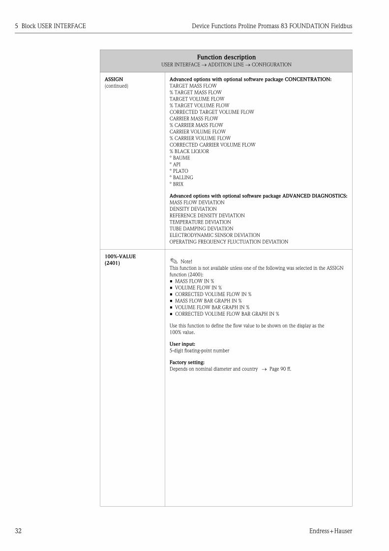
A0001253
1 = main line, 2 = additional line, 3 = information line
ASSIGN
(2200)
In this function, a value to be displayed is assigned to the main line (top line in the local
display). This value is displayed during normal operation.
Options (standard):
OFF
MASS FLOW
MASS FLOW IN %
VOLUME FLOW
VOLUME FLOW IN %
CORRECTED VOLUME FLOW
CORRECTED VOLUME FLOW IN %
DENSITY
REFERENCE DENSITY
TEMPERATURE
TOTALIZER (1 to 3)
AI (1 to 8) - OUT VALUE
PID - IN VALUE (controlled variable)
PID - CAS_IN VALUE (external set point)
PID - OUT VALUE (manipulated variable)
Factory setting:
MASS FLOW
(Continued on next page)
Esc
E+-
1
2
3

5 Block USER INTERFACE Device Functions Proline Promass 83 FOUNDATION Fieldbus
28 Endress+Hauser
ASSIGN
(continued)
Advanced options with optional software package CONCENTRATION:
TARGET MASS FLOW
% TARGET MASS FLOW
TARGET VOLUME FLOW
% TARGET VOLUME FLOW
CORRECTED TARGET VOLUME FLOW
CARRIER MASS FLOW
% CARRIER MASS FLOW
CARRIER VOLUME FLOW
% CARRIER VOLUME FLOW
CORRECTED CARRIER VOLUME FLOW
% BLACK LIQUOR
° BAUME
° API
° PLATO
° BALLING
° BRIX
Advanced options with optional software package ADVANCED DIAGNOSTICS:
MASS FLOW DEVIATION
DENSITY DEVIATION
REFERENCE DENSITY DEVIATION
TEMPERATURE DEVIATION
TUBE DAMPING DEVIATION
ELECTRODYNAMIC SENSOR DEVIATION
OPERATING FREQUENCY FLUCTUATION DEVIATION
TUBE DAMPING FLUCTUATION DEVIATION
100%-VALUE
(2201) ! Note!
This function is not available unless one of the following was selected in the ASSIGN
function (2200):
• MASS FLOW IN %
• VOLUME FLOW IN %
• CORRECTED VOLUME FLOW IN %
Use this function to define the flow value to be shown on the display as the 100%
value.
User input:
5-digit floating-point number
Factory setting:
Depends on nominal diameter and country → Page 90 ff.
FORMAT
(2202)
Use this function to define the maximum number of places after the decimal point
displayed for the reading in the main line.
Options:
XXXXX. - XXXX.X - XXX.XX - XX.XXX -X.XXXX
Factory setting:
X.XXXX
! Note!
• Note that this setting only affects the reading as it appears on the display, it has no
influence on the accuracy of the system's calculations.
• The places after the decimal point as computed by the measuring device cannot
always be displayed, depending on this setting and the engineering unit. In these
instances an arrow appears on the display between the measured value and the
engineering unit (e.g. 1.2 → kg/h), indicating that the measuring system is
computing with more decimal places than can be shown on the display.
Function descriptionUSER INTERFACE → MAIN LINE → CONFIGURATION

Device Functions Proline Promass 83 FOUNDATION Fieldbus 5 Block USER INTERFACE
Endress+Hauser 29
5.2.2 Function group MULTIPLEX
USER INTERFACE C ⇒ CONTROL CAA
⇓
MAIN LINE CCA ⇒ CONFIGURATION 220
⇓
MULTIPLEX 222
Function descriptionUSER INTERFACE → MAIN LINE → MULTIPLEX
ASSIGN
(2220)
Use this function to define the second reading to be displayed in the main line
alternately (every 10 seconds) with the value defined in the ASSIGN function (2200).
Options (standard):
OFF
MASS FLOW
MASS FLOW IN %
VOLUME FLOW
VOLUME FLOW IN %
CORRECTED VOLUME FLOW
CORRECTED VOLUME FLOW IN %
DENSITY
REFERENCE DENSITY
TEMPERATURE
TOTALIZER (1 to 3)
AI (1 to 8) - OUT VALUE
PID - IN VALUE (controlled variable)
PID - CAS_IN VALUE (external set point)
PID - OUT VALUE (manipulated variable)
Factory setting:
OFF
Advanced options with optional software package CONCENTRATION:
TARGET MASS FLOW
% TARGET MASS FLOW
TARGET VOLUME FLOW
% TARGET VOLUME FLOW
CORRECTED TARGET VOLUME FLOW
CARRIER MASS FLOW
% CARRIER MASS FLOW
CARRIER VOLUME FLOW
% CARRIER VOLUME FLOW
CORRECTED CARRIER VOLUME FLOW
% BLACK LIQUOR
° BAUME
° API
° PLATO
° BALLING
° BRIX
(Continued on next page)

5 Block USER INTERFACE Device Functions Proline Promass 83 FOUNDATION Fieldbus
30 Endress+Hauser
ASSIGN
(continued)
Advanced options with optional software package ADVANCED DIAGNOSTICS:
MASS FLOW DEVIATION
DENSITY DEVIATION
REFERENCE DENSITY DEVIATION
TEMPERATURE DEVIATION
TUBE DAMPING DEVIATION
ELECTRODYNAMIC SENSOR DEVIATION
OPERATING FREQUENCY FLUCTUATION DEVIATION
TUBE DAMPING FLUCTUATION DEVIATION
100%-VALUE
(2221) ! Note!
This function is not available unless one of the following was selected in the ASSIGN
function (2220):
• MASS FLOW IN %
• VOLUME FLOW IN %
• CORRECTED VOLUME FLOW IN %
Use this function to define the flow value to be shown on the display as the
100% value.
User input:
5-digit floating-point number
Factory setting:
Depends on nominal diameter and country → Page 90 ff.
FORMAT
(2222)
Use this function to define the maximum number of places after the decimal point for
the second value displayed in the main line.
Options:
XXXXX. - XXXX.X - XXX.XX - XX.XXX -X.XXXX
Factory setting:
X.XXXX
! Note!
• Note that this setting only affects the reading as it appears on the display, it has no
influence on the accuracy of the system's calculations.
• The places after the decimal point as computed by the measuring device cannot
always be displayed, depending on this setting and the engineering unit. In these
instances an arrow appears on the display between the measured value and the
engineering unit (e.g. 1.2 → kg/h), indicating that the measuring system is
computing with more decimal places than can be shown on the display.
Function descriptionUSER INTERFACE → MAIN LINE → MULTIPLEX

Device Functions Proline Promass 83 FOUNDATION Fieldbus 5 Block USER INTERFACE
Endress+Hauser 31
5.3 Group ADDITION LINE
5.3.1 Function group CONFIGURATION
USER INTERFACE C ⇒ CONTROL CAA
⇓
MAIN LINE CCA
⇓
ADDITION LINE CEA ⇒ CONFIGURATION 240
Function descriptionUSER INTERFACE → ADDITION LINE → CONFIGURATION
A0001253
1 = main line, 2 = additional line, 3 = information line
ASSIGN
(2400)
In this function, a value to be displayed is assigned to the additional line (middle line in
the local display). This value is displayed during normal operation.
Options (standard):
OFF
MASS FLOW
MASS FLOW IN %
VOLUME FLOW
VOLUME FLOW IN %
CORRECTED VOLUME FLOW
CORRECTED VOLUME FLOW IN %
DENSITY
REFERENCE DENSITY
TEMPERATURE
MASS FLOW BAR GRAPH IN %
VOLUME FLOW BAR GRAPH IN %
CORRECTED VOLUME FLOW BAR GRAPH IN %
TOTALIZER (1 to 3)
AI (1 to 8) - OUT VALUE
PID - IN VALUE (controlled variable)
PID - CAS_IN VALUE (external set point)
PID - OUT VALUE (manipulated variable)
DEVICE PD-TAG
Factory setting:
TOTALIZER 1
(Continued on next page)
Esc
E+-
1
2
3
5 Block USER INTERFACE Device Functions Proline Promass 83 FOUNDATION Fieldbus
32 Endress+Hauser
ASSIGN
(continued)
Advanced options with optional software package CONCENTRATION:
TARGET MASS FLOW
% TARGET MASS FLOW
TARGET VOLUME FLOW
% TARGET VOLUME FLOW
CORRECTED TARGET VOLUME FLOW
CARRIER MASS FLOW
% CARRIER MASS FLOW
CARRIER VOLUME FLOW
% CARRIER VOLUME FLOW
CORRECTED CARRIER VOLUME FLOW
% BLACK LIQUOR
° BAUME
° API
° PLATO
° BALLING
° BRIX
Advanced options with optional software package ADVANCED DIAGNOSTICS:
MASS FLOW DEVIATION
DENSITY DEVIATION
REFERENCE DENSITY DEVIATION
TEMPERATURE DEVIATION
TUBE DAMPING DEVIATION
ELECTRODYNAMIC SENSOR DEVIATION
OPERATING FREQUENCY FLUCTUATION DEVIATION
100%-VALUE
(2401) ! Note!
This function is not available unless one of the following was selected in the ASSIGN
function (2400):
• MASS FLOW IN %
• VOLUME FLOW IN %
• CORRECTED VOLUME FLOW IN %
• MASS FLOW BAR GRAPH IN %
• VOLUME FLOW BAR GRAPH IN %
• CORRECTED VOLUME FLOW BAR GRAPH IN %
Use this function to define the flow value to be shown on the display as the
100% value.
User input:
5-digit floating-point number
Factory setting:
Depends on nominal diameter and country → Page 90 ff.
Function descriptionUSER INTERFACE → ADDITION LINE → CONFIGURATION

Device Functions Proline Promass 83 FOUNDATION Fieldbus 5 Block USER INTERFACE
Endress+Hauser 33
FORMAT
(2402) ! Note!
This function is not available unless a number was selected in the ASSIGN function
(2400).
Use this function to define the maximum number of places after the decimal point
displayed for the reading in the additional line.
Options:
XXXXX. - XXXX.X - XXX.XX - XX.XXX -X.XXXX
Factory setting:
X.XXXX
! Note!
• Note that this setting only affects the reading as it appears on the display, it has no
influence on the accuracy of the system's calculations.
• The places after the decimal point as computed by the measuring device cannot
always be displayed, depending on this setting and the engineering unit. In these
instances an arrow appears on the display between the measured value and the
engineering unit (e.g. 1.2 → kg/h), indicating that the measuring system is
computing with more decimal places than can be shown on the display.
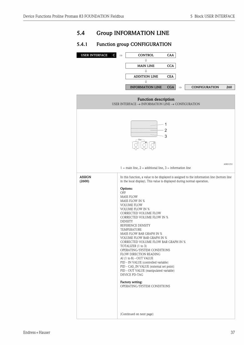
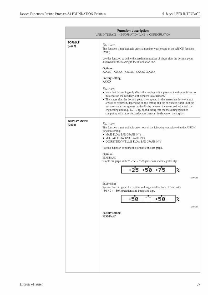
DISPLAY MODE
(2403) ! Note!
This function is not available unless one of the following was selected in the ASSIGN
function (2400):
• MASS FLOW BAR GRAPH IN %
• VOLUME FLOW BAR GRAPH IN %
• CORRECTED VOLUME FLOW BAR GRAPH IN %
Use this function to define the format of the bar graph.
Options:
STANDARD
Simple bar graph with 25 / 50 / 75% gradations and integrated sign.
A0001258
SYMMETRY
Symmetrical bar graph for positive and negative directions of flow, with
–50 / 0 / +50% gradations and integrated sign.
A0001259
Factory setting:
STANDARD
Function descriptionUSER INTERFACE → ADDITION LINE → CONFIGURATION

5 Block USER INTERFACE Device Functions Proline Promass 83 FOUNDATION Fieldbus
34 Endress+Hauser
5.3.2 Function group MULTIPLEX
USER INTERFACE C ⇒ CONTROL CAA
⇓
MAIN LINE CCA
⇓
ADDITION LINE CEA ⇒ CONFIGURATION 240
⇓
MULTIPLEX 242
Function descriptionUSER INTERFACE → ADDITION LINE → MULTIPLEX
ASSIGN
(2420)
Use this function to define the second reading to be displayed in the additional line
alternately (every 10 seconds) with the value defined in the ASSIGN function (2400).
Options (standard):
OFF
MASS FLOW
MASS FLOW IN %
VOLUME FLOW
VOLUME FLOW IN %
CORRECTED VOLUME FLOW
CORRECTED VOLUME FLOW IN %
DENSITY
REFERENCE DENSITY
TEMPERATURE
MASS FLOW BAR GRAPH IN %
VOLUME FLOW BAR GRAPH IN %
CORRECTED VOLUME FLOW BAR GRAPH IN %
TOTALIZER (1 to 3)
AI (1 to 8) - OUT VALUE
PID - IN VALUE (controlled variable)
PID - CAS_IN VALUE (external set point)
PID - OUT VALUE (manipulated variable)
DEVICE PD-TAG
Factory setting:
OFF
Advanced options with optional software package CONCENTRATION:
TARGET MASS FLOW
% TARGET MASS FLOW
TARGET VOLUME FLOW
% TARGET VOLUME FLOW
CORRECTED TARGET VOLUME FLOW
CARRIER MASS FLOW
% CARRIER MASS FLOW
CARRIER VOLUME FLOW
% CARRIER VOLUME FLOW
CORRECTED CARRIER VOLUME FLOW
% BLACK LIQUOR
° BAUME
° API
° PLATO
° BALLING
° BRIX
(Continued on next page)

Device Functions Proline Promass 83 FOUNDATION Fieldbus 5 Block USER INTERFACE
Endress+Hauser 35
ASSIGN
(continued)
Advanced options with optional software package ADVANCED DIAGNOSTICS:
MASS FLOW DEVIATION
DENSITY DEVIATION
REFERENCE DENSITY DEVIATION
TEMPERATURE DEVIATION
TUBE DAMPING DEVIATION
ELECTRODYNAMIC SENSOR DEVIATION
OPERATING FREQUENCY FLUCTUATION DEVIATION
TUBE DAMPING FLUCTUATION DEVIATION
! Note!
Multiplex mode is suspended as soon as a fault/notice message is generated.
The message in question appears on the display.
• Fault message (identified by a lightning icon):
Multiplex mode is resumed as soon as the fault is no longer active.
• Notice message (identified by an exclamation mark):
Multiplex mode is resumed as soon as the notice message is no longer active.
100%-VALUE
(2421) ! Note!
This function is not available unless one of the following was selected in the ASSIGN
function (2420):
• MASS FLOW IN %
• VOLUME FLOW IN %
• CORRECTED VOLUME FLOW IN %
• MASS FLOW BAR GRAPH IN %
• VOLUME FLOW BAR GRAPH IN %
• CORRECTED VOLUME FLOW BAR GRAPH IN %
Use this function to define the flow value to be shown on the display as the
100% value.
User input:
5-digit floating-point number
Factory setting:
Depends on nominal diameter and country → Page 90 ff.
FORMAT
(2422) ! Note!
This function is not available unless a number was selected in the ASSIGN function
(2420).
Use this function to define the maximum number of places after the decimal point for
the second value displayed in the additional line.
Options:
XXXXX. - XXXX.X - XXX.XX - XX.XXX -X.XXXX
Factory setting:
X.XXXX
! Note!
• Note that this setting only affects the reading as it appears on the display, it has no
influence on the accuracy of the system's calculations.
• The places after the decimal point as computed by the measuring device cannot
always be displayed, depending on this setting and the engineering unit. In these
instances an arrow appears on the display between the measured value and the
engineering unit (e.g. 1.2 → kg/h), indicating that the measuring system is
computing with more decimal places than can be shown on the display.
Function descriptionUSER INTERFACE → ADDITION LINE → MULTIPLEX

5 Block USER INTERFACE Device Functions Proline Promass 83 FOUNDATION Fieldbus
36 Endress+Hauser
DISPLAY MODE
(2423) ! Note!
This function is not available unless one of the following was selected in the ASSIGN
function (2420):
• MASS FLOW BAR GRAPH IN %
• VOLUME FLOW BAR GRAPH IN %
• CORRECTED VOLUME FLOW BAR GRAPH IN %
Use this function to define the format of the bar graph.
Options:
STANDARD
Simple bar graph with 25 / 50 / 75% gradations and integrated sign.
A0001258
SYMMETRY
Symmetrical bar graph for positive and negative directions of flow, with
–50 / 0 / +50% gradations and integrated sign.
A0001259
Factory setting:
STANDARD
Function descriptionUSER INTERFACE → ADDITION LINE → MULTIPLEX
Device Functions Proline Promass 83 FOUNDATION Fieldbus 5 Block USER INTERFACE
Endress+Hauser 37
5.4 Group INFORMATION LINE
5.4.1 Function group CONFIGURATION
USER INTERFACE C ⇒ CONTROL CAA
⇓
MAIN LINE CCA
⇓
ADDITION LINE CEA
⇓
INFORMATION LINE CGA ⇒ CONFIGURATION 260
Function descriptionUSER INTERFACE → INFORMATION LINE → CONFIGURATION
A0001253
1 = main line, 2 = additional line, 3 = information line
ASSIGN
(2600)
In this function, a value to be displayed is assigned to the information line (bottom line
in the local display). This value is displayed during normal operation.
Options:
OFF
MASS FLOW
MASS FLOW IN %
VOLUME FLOW
VOLUME FLOW IN %
CORRECTED VOLUME FLOW
CORRECTED VOLUME FLOW IN %
DENSITY
REFERENCE DENSITY
TEMPERATURE
MASS FLOW BAR GRAPH IN %
VOLUME FLOW BAR GRAPH IN %
CORRECTED VOLUME FLOW BAR GRAPH IN %
TOTALIZER (1 to 3)
OPERATING/SYSTEM CONDITIONS
FLOW DIRECTION READING
AI (1 to 8) - OUT VALUE
PID - IN VALUE (controlled variable)
PID - CAS_IN VALUE (external set point)
PID - OUT VALUE (manipulated variable)
DEVICE PD-TAG
Factory setting:
OPERATING/SYSTEM CONDITIONS
(Continued on next page)
Esc
E+-
1
2
3

5 Block USER INTERFACE Device Functions Proline Promass 83 FOUNDATION Fieldbus
38 Endress+Hauser
ASSIGN
(continued)
Advanced options with optional software package CONCENTRATION:
TARGET MASS FLOW
% TARGET MASS FLOW
TARGET VOLUME FLOW
% TARGET VOLUME FLOW
CORRECTED TARGET VOLUME FLOW
CARRIER MASS FLOW
% CARRIER MASS FLOW
CARRIER VOLUME FLOW
% CARRIER VOLUME FLOW
CORRECTED CARRIER VOLUME FLOW
% BLACK LIQUOR
° BAUME
° API
° PLATO
° BALLING
° BRIX
Advanced options with optional software package ADVANCED DIAGNOSTICS:
MASS FLOW DEVIATION
DENSITY DEVIATION
REFERENCE DENSITY DEVIATION
TEMPERATURE DEVIATION
TUBE DAMPING DEVIATION
ELECTRODYNAMIC SENSOR DEVIATION
OPERATING FREQUENCY FLUCTUATION DEVIATION
TUBE DAMPING FLUCTUATION DEVIATION
100%-VALUE
(2601) ! Note!
This function is not available unless one of the following was selected in the ASSIGN
function (2600):
• MASS FLOW IN %
• VOLUME FLOW IN %
• CORRECTED VOLUME FLOW IN %
• MASS FLOW BAR GRAPH IN %
• VOLUME FLOW BAR GRAPH IN %
• CORRECTED VOLUME FLOW BAR GRAPH IN %
Use this function to define the flow value to be shown on the display as the
100% value.
User input:
5-digit floating-point number
Factory setting:
Depends on nominal diameter and country → Page 90 ff.
Function descriptionUSER INTERFACE → INFORMATION LINE → CONFIGURATION
Device Functions Proline Promass 83 FOUNDATION Fieldbus 5 Block USER INTERFACE
Endress+Hauser 39
FORMAT
(2602) ! Note!
This function is not available unless a number was selected in the ASSIGN function
(2600).
Use this function to define the maximum number of places after the decimal point
displayed for the reading in the information line.
Options:
XXXXX. - XXXX.X - XXX.XX - XX.XXX -X.XXXX
Factory setting:
X.XXXX
! Note!
• Note that this setting only affects the reading as it appears on the display, it has no
influence on the accuracy of the system's calculations.
• The places after the decimal point as computed by the measuring device cannot
always be displayed, depending on this setting and the engineering unit. In these
instances an arrow appears on the display between the measured value and the
engineering unit (e.g. 1.2 → kg/h), indicating that the measuring system is
computing with more decimal places than can be shown on the display.
DISPLAY MODE
(2603) ! Note!
This function is not available unless one of the following was selected in the ASSIGN
function (2600):
• MASS FLOW BAR GRAPH IN %
• VOLUME FLOW BAR GRAPH IN %
• CORRECTED VOLUME FLOW BAR GRAPH IN %
Use this function to define the format of the bar graph.
Options:
STANDARD
Simple bar graph with 25 / 50 / 75% gradations and integrated sign.
A0001258
SYMMETRY
Symmetrical bar graph for positive and negative directions of flow, with
–50 / 0 / +50% gradations and integrated sign.
A0001259
Factory setting:
STANDARD
Function descriptionUSER INTERFACE → INFORMATION LINE → CONFIGURATION

5 Block USER INTERFACE Device Functions Proline Promass 83 FOUNDATION Fieldbus
40 Endress+Hauser
5.4.2 Function group MULTIPLEX
USER INTERFACE C ⇒ CONTROL CAA
⇓
MAIN LINE CCA
⇓
ADDITION LINE CEA
⇓
INFORMATION LINE CGA ⇒ CONFIGURATION 260
⇓
MULTIPLEX 262
Function descriptionUSER INTERFACE → INFORMATION LINE → MULTIPLEX
ASSIGN
(2620)
Use this function to define the second reading to be displayed in the information line
alternately (every 10 seconds) with the value defined in the ASSIGN function (2600).
Options:
OFF
MASS FLOW
MASS FLOW IN %
VOLUME FLOW
VOLUME FLOW IN %
CORRECTED VOLUME FLOW
CORRECTED VOLUME FLOW IN %
DENSITY
REFERENCE DENSITY
TEMPERATURE
MASS FLOW BAR GRAPH IN %
VOLUME FLOW BAR GRAPH IN %
CORRECTED VOLUME FLOW BAR GRAPH IN %
TOTALIZER (1 to 3)
OPERATING/SYSTEM CONDITION
FLOW DIRECTION READING
AI (1 to 8) - OUT VALUE
PID - IN VALUE (controlled variable)
PID - CAS_IN VALUE (external set point)
PID - OUT VALUE (manipulated variable)
DEVICE PD-TAG
Factory setting:
OFF
(Continued on next page)

Device Functions Proline Promass 83 FOUNDATION Fieldbus 5 Block USER INTERFACE
Endress+Hauser 41
ASSIGN
(2620)
(Continued)
Advanced options with optional software package CONCENTRATION:
TARGET MASS FLOW
% TARGET MASS FLOW
TARGET VOLUME FLOW
% TARGET VOLUME FLOW
CORRECTED TARGET VOLUME FLOW
CARRIER MASS FLOW
% CARRIER MASS FLOW
CARRIER VOLUME FLOW
% CARRIER VOLUME FLOW
CORRECTED CARRIER VOLUME FLOW
% BLACK LIQUOR
° BAUME
° API
° PLATO
° BALLING
° BRIX
Advanced options with optional software package ADVANCED DIAGNOSTICS:
MASS FLOW DEVIATION
DENSITY DEVIATION
REFERENCE DENSITY DEVIATION
TEMPERATURE DEVIATION
TUBE DAMPING DEVIATION
ELECTRODYNAMIC SENSOR DEVIATION
OPERATING FREQUENCY FLUCTUATION DEVIATION
TUBE DAMPING FLUCTUATION DEVIATION
! Note!
Multiplex mode is suspended as soon as a fault/notice message is generated.
The message in question appears on the display.
• Fault message (identified by a lightning icon):
Multiplex mode is resumed as soon as the fault is no longer active.
• Notice message (identified by an exclamation mark):
Multiplex mode is resumed as soon as the notice message is no longer active.
100%-VALUE
(2621) ! Note!
This function is not available unless one of the following was selected in the ASSIGN
function (2620):
• MASS FLOW IN %
• VOLUME FLOW IN %
• CORRECTED VOLUME FLOW IN %
• MASS FLOW BAR GRAPH IN %
• VOLUME FLOW BAR GRAPH IN %
• CORRECTED VOLUME FLOW BAR GRAPH IN %
Use this function to define the flow value to be shown on the display as the
100% value.
User input:
5-digit floating-point number
Factory setting:
Depends on nominal diameter and country → Page 90 ff.
Function descriptionUSER INTERFACE → INFORMATION LINE → MULTIPLEX

5 Block USER INTERFACE Device Functions Proline Promass 83 FOUNDATION Fieldbus
42 Endress+Hauser
FORMAT
(2622) ! Note!
This function is not available unless a number was selected in the ASSIGN function
(2620).
Use this function to define the maximum number of places after the decimal point for
the second value displayed in the information line.
Options:
XXXXX. - XXXX.X - XXX.XX - XX.XXX -X.XXXX
Factory setting:
X.XXXX
! Note!
• Note that this setting only affects the reading as it appears on the display, it has no
influence on the accuracy of the system's calculations.
• The places after the decimal point as computed by the measuring device cannot
always be displayed, depending on this setting and the engineering unit. In these
instances an arrow appears on the display between the measured value and the
engineering unit (e.g. 1.2 → kg/h), indicating that the measuring system is
computing with more decimal places than can be shown on the display.
DISPLAY MODE
(2623) ! Note!
This function is not available unless one of the following was selected in the ASSIGN
function (2620):
• MASS FLOW BAR GRAPH IN %
• VOLUME FLOW BAR GRAPH IN %
• CORRECTED VOLUME FLOW BAR GRAPH IN %
Use this function to define the format of the bar graph.
Options:
STANDARD
Simple bar graph with 25 / 50 / 75% gradations and integrated sign.
A0001258
SYMMETRY
Symmetrical bar graph for positive and negative directions of flow, with
-50 / 0 / +50% gradations and integrated sign.
A0001259
Factory setting:
STANDARD
Function descriptionUSER INTERFACE → INFORMATION LINE → MULTIPLEX
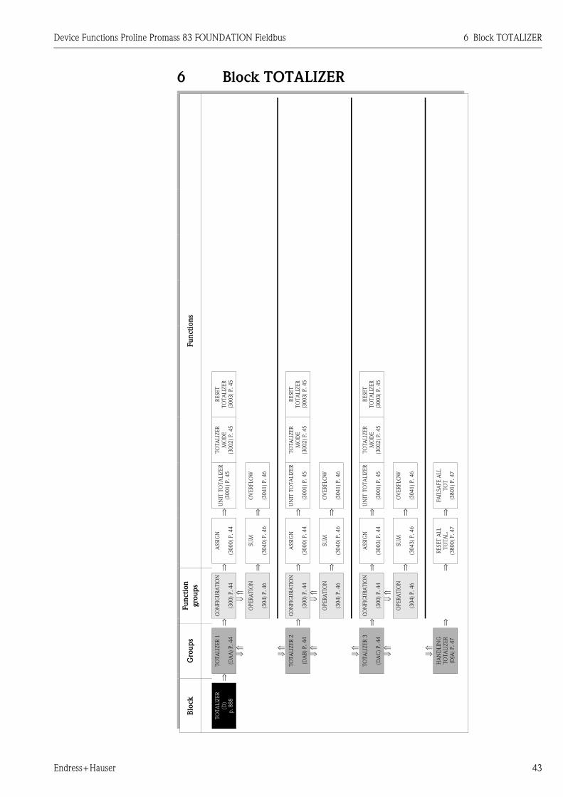
Device Functions Proline Promass 83 FOUNDATION Fieldbus 6 Block TOTALIZER
Endress+Hauser 43
6 Block TOTALIZER
Fu
ncti
on
s
RE
SE
T
TO
TA
LIZ
ER
(30
03
) P
.4
5
RE
SE
T
TO
TA
LIZ
ER
(30
03
) P
.4
5
RE
SE
T
TO
TA
LIZ
ER
(30
03
) P
.4
5
TO
TA
LIZ
ER
MO
DE
(30
02
) P
.4
5
TO
TA
LIZ
ER
MO
DE
(30
02
) P
.4
5
TO
TA
LIZ
ER
MO
DE
(30
02
) P
.4
5
UN
IT T
OT
ALIZ
ER
(30
01
) P
.4
5
OV
ER
FLO
W
(30
41
) P
.4
6
UN
IT T
OT
ALIZ
ER
(30
01
) P
.4
5
OV
ER
FLO
W
(30
41
) P
.4
6
UN
IT T
OT
ALIZ
ER
(30
01
) P
.4
5
OV
ER
FLO
W
(30
41
) P
.4
6
FA
ILSA
FE
ALL
TO
T
(38
01
) P
.4
7
⇒ ⇒ ⇒ ⇒ ⇒ ⇒ ⇒
ASSIG
N
(30
00
) P
.4
4
SU
M
(30
40
) P
.4
6
ASSIG
N
(30
00
) P
.4
4
SU
M
(30
40
) P
.4
6
ASSIG
N
(30
03
) P
.4
4
SU
M
(30
43
) P
.4
6
RE
SE
T A
LL
TO
TA
L.
(38
00
) P
.4
7
⇒ ⇒ ⇒ ⇒ ⇒ ⇒ ⇒
Fun
cti
on
gro
up
s
CO
NFIG
UR
AT
ION
(30
0)
P.4
4
⇓ ⇑
OPE
RA
TIO
N
(30
4)
P.4
6
CO
NFIG
UR
AT
ION
(30
0)
P.4
4
⇓ ⇑
OPE
RA
TIO
N
(30
4)
P.4
6
CO
NFIG
UR
AT
ION
(30
0)
P.4
4
⇓ ⇑
OPE
RA
TIO
N
(30
4) P
.46
⇒ ⇒ ⇒ ⇒
Gro
up
s
TO
TA
LIZ
ER
1
(DA
A) P
.44
⇓ ⇑
⇓ ⇑
TO
TA
LIZ
ER
2
(DA
B) P
.44
⇓ ⇑
⇓ ⇑
TO
TA
LIZ
ER
3
(DA
C)
P.
44
⇓ ⇑
⇓ ⇑
HA
ND
LIN
G
TO
TA
LIZ
ER
(DJA
) P.
47
⇒
Blo
ck
TO
TA
LIZ
ER
(D)
p. 888

6 Block TOTALIZER Device Functions Proline Promass 83 FOUNDATION Fieldbus
44 Endress+Hauser
6.1 Group TOTALIZERS (1 to 3)
6.1.1 Function group CONFIGURATION
TOTALIZER D ⇒ TOTALIZER 1 DAA ⇒ CONFIGURATION 300
⇓
TOTALIZER 2 DAB ⇒ CONFIGURATION 300
⇓
TOTALIZER 3 DAC ⇒ CONFIGURATION 300
Function descriptionTOTALIZER → TOTALIZERS (1 to 3) → CONFIGURATION
The function descriptions below apply to totalizers 1 to 3; the totalizers are independently configurable.
ASSIGN
(3000)
Use this function to assign a measured variable to the totalizer.
Options (standard):
OFF
MASS FLOW
VOLUME FLOW
CORRECTED VOLUME FLOW
Advanced options with optional software package CONCENTRATION:
TARGET MASS FLOW
TARGET VOLUME FLOW
CORRECTED TARGET VOLUME FLOW
CARRIER MASS FLOW
CARRIER VOLUME FLOW
CORRECTED CARRIER VOLUME FLOW
Factory setting:
MASS FLOW
! Note!
• The totalizer is reset to "0" as soon as the selection is changed.
• If you select OFF, the ASSIGN function (3000) is the only function shown in the
CONFIGURATION function group of the totalizer in question.

Device Functions Proline Promass 83 FOUNDATION Fieldbus 6 Block TOTALIZER
Endress+Hauser 45
UNIT TOTALIZER
(3001)
Use this function to define the unit for the totalizer's measured variable, as selected
beforehand.
Options (for the MASS FLOW assignment):
Metric → g; kg; t
US → oz; lb; ton
Factory setting:
kg
Options (for the VOLUME FLOW assignment):
Metric → cm3; dm3; m3; ml; l; hl; Ml Mega
US → cc; af; ft3; oz f; gal; Kgal; Mgal; bbl (normal fluids); bbl (beer);
bbl (petrochemicals); bbl (filling tanks)
Imperial → gal; Mgal; bbl (beer); bbl (petrochemicals)
Factory setting:
m3
Options (for the CORRECTED VOLUME FLOW assignment):
Metric → Nl; Nm3
US → Sm3; Scf
Factory setting:
Nm3
! Note!
The unit selected here has no effect on the fieldbus. It is only used for the local display
and for assigned instrument functions.
TOTALIZER MODE
(3002)
Use this function to define how the flow components are to be totaled by the totalizer.
Options:
BALANCE
Positive and negative flow components. The positive and negative flow components are
balanced. In other words, net flow in the flow direction is registered.
FORWARD
Only positive flow components
REVERSE
Negative flow components only
Factory setting:
Totalizer 1 = BALANCE
Totalizer 2 = FORWARD
Totalizer 3 = REVERSE
RESET
TOTALIZERS
(3003)
Use this function to reset the sum and the overflow of the totalizer to zero.
Options:
NO
YES
Factory setting:
NO
Function descriptionTOTALIZER → TOTALIZERS (1 to 3) → CONFIGURATION

6 Block TOTALIZER Device Functions Proline Promass 83 FOUNDATION Fieldbus
46 Endress+Hauser
6.1.2 Function group OPERATION
TOTALIZER D ⇒ TOTALIZER 1 DAA ⇒ CONFIGURATION 300
⇓
⇓ OPERATION 304
TOTALIZER 2 DAB ⇒ CONFIGURATION 300
⇓
⇓ OPERATION 304
TOTALIZER 3 DAC ⇒ CONFIGURATION 300
⇓
OPERATION 304
Function descriptionTOTALIZER → TOTALIZERS (1 to 3) → OPERATION
The function descriptions below apply to totalizers 1 to 3; the totalizers are independently configurable.
SUM
(3040)
Use this function to view the total for the totalizer's measured variable aggregated since
measuring commenced. The value can be positive or negative, depending on the setting
selected in the TOTALIZER MODE function (3002), and the direction of flow.
Display:
Max. 7-digit floating-point number, including unit and sign
(e.g. 15467.04 m3; –4925.631 kg)
! Note!
• The effect of the setting in the TOTALIZER MODE function (3002) is as follows:
– If the setting is BALANCE, the totalizer balances flow in the positive and negative
directions.
– If the setting is FORWARD, the totalizer registers only flow in the positive direction.
– If the setting is REVERSE, the totalizer registers only flow in the negative direction.
• The totalizers' response to faults is defined in the FAILSAFE MODE function (3801).
OVERFLOW
(3041)
Use this function to view the overflow for the totalizer aggregated since measuring
commenced.
Total flow quantity is represented by a floating-point number consisting of
max. 7 digits. You can use this function to view higher numerical values (>9999999)
as overflows. The effective quantity is thus the total of OVERFLOW plus the value
returned by the SUM function.
Example:
Reading for 2 overflows: 2 107 kg (= 20000000 kg)
The value returned by the SUM function = 196845.7 kg
Effective total quantity = 20196845.7 kg
Display:
Integer with exponent, including sign and unit, e.g. 2 107kg

Device Functions Proline Promass 83 FOUNDATION Fieldbus 6 Block TOTALIZER
Endress+Hauser 47
6.2 Group HANDLING TOTALIZER
TOTALIZER D ⇒ TOTALIZER 1 DAA
⇓
TOTALIZER 2 DAB
⇓
TOTALIZER 3 DAC
⇓
INVENTORY DGA
⇓
HANDLING TOTALIZER DJA ⇒ Handling totalizer functions
Function descriptionTOTALIZER → HANDLING TOTALIZER → Handling totalizer functions
RESET ALL
TOTALIZERS
(3800)
Use this function to reset the totals (including all overflows) of the totalizers (1 to 3) to
zero (= RESET).
Options:
NO
YES
Factory setting:
NO
FAILSAFE MODE
(3801)
Use this function to define the common response of all totalizers (1 to 3) in case of
error.
Options:
STOP
The totalizers are paused until the fault is rectified.
ACTUAL VALUE
The totalizers continue to count based on the current flow measured value. The fault is
ignored.
HOLD VALUE
The totalizers continue to count the flow based on the last valid flow value (before the
fault occurred).
Factory setting:
STOP

7 Block BASIC FUNCTION Device Functions Proline Promass 83 FOUNDATION Fieldbus
48 Endress+Hauser
7 Block BASIC FUNCTIONFun
cti
on
s
RE
ST
. O
RIG
INA
L
(64
88
) P
.5
8
DE
NSIT
Y
AD
JUST
ME
NT
(64
87
) P
.5
8
ME
ASU
RE
FLU
ID
2
(64
86
) P
.5
8
C5
(68
55
) P
.6
3
DD
RE
VIS
ION
(62
44
) P
.5
1
EP
D
EX
C.C
UR
R.M
AX
(64
26
) P
.5
5
RE
FE
RE
NC
E
TE
MP
ER
AT
UR
E
(64
64
) P
.5
6
DE
NSIT
Y
SE
TPO
INT
2
(64
85
) P
.5
8
CO
EFF. K
D2
(68
44
) P
.6
2
C4
(68
54
) P
.6
3
CA
SC
AD
E I
N
(62
23
) P
.5
0
DE
VIC
E
RE
VIS
ION
(62
43
) P
.5
1
PR
ESS. SH
OC
K
SU
PP.
(64
04
) P
.5
3
EPD
RE
SPO
NSE
TIM
E
(64
25
) P
.5
4
EX
P.
CO
EF.
SQ
R.
(64
63
) P
.5
6
ME
ASU
RE
FLU
ID
1
(64
84
) P
.5
7
PO
SIT
IVE
ZE
RO
RE
T.
(66
05
) P
.6
0
CO
EFF. K
D1
(68
43
) P
.6
2
C3
(68
53
) P
.6
3
MA
X T
EM
P.
CA
RR
.
(68
63
) P
.6
4
DE
VIC
E P
D-T
AG
(62
03
) P
.4
9
PID
_IN
VA
LU
E
(62
22
) P
.5
0
SE
RIA
L N
UM
BE
R
(62
42
) P
.5
1
OFF-V
ALU
E L
F
CU
T O
FF
(64
03
) P
.5
2
EPD
VA
LU
E
HIG
H
(64
24
) P
.5
4
EX
P.C
OE
F.L
IN.
(64
62
) P
.5
6
DE
NSIT
Y
SE
TPO
INT
1
(64
83
) P
.5
7
FLO
W D
AM
PIN
G
(66
03
) P
.6
0
NO
MIN
AL
DIA
ME
TE
R
(68
04
) P
.6
1
CO
EFF. K
T
(68
42
) P
.6
2
C2
(68
52
) P
.6
3
MIN
TE
MP.
CA
RR
.
(68
62
) P
.6
4
SIM
ULA
TIO
N
(62
01
) P
.4
9
PID
_O
UT
VA
LU
E
(62
21
) P
.5
0
DE
VIC
E T
YP
E
(62
41
) P
.5
1
ON
-VA
LU
E L
F
CU
T O
FF
(64
02
) P
.5
2
EP
D V
ALU
E L
OW
(64
23
) P
.5
4
FIX
ED
RE
F.
DE
NSIT
Y
(64
61
) P
.5
5
DE
NSIT
Y A
DJU
ST
MO
DE
(64
82
) P
.5
7
PR
ESSU
RE
(65
01
) P
.5
9
DE
NSIT
Y
DA
MPIN
G
(66
02
) P
.6
0
ZE
RO
PO
INT
(68
03
) P
.6
1
CO
EFF. K
M2
(68
41
) P
.6
2
C1
(68
51
) P
.6
3
MA
X T
EM
P
ME
AS.
(68
61
) P
.6
4
⇒ ⇒ ⇒ ⇒ ⇒ ⇒ ⇒ ⇒ ⇒ ⇒ ⇒ ⇒ ⇒
WR
ITE
PR
OT
EC
TIO
N
(62
00
) P
.4
9
BLO
CK
SE
LE
CT
ION
(62
20
) P
.5
0
MA
NU
FA
CT
UR
ER
ID
(62
40
) P
.5
1
ASSIG
N L
F C
UT
OFF
(64
00
) P
.5
2
EP
D
(64
20
) P
.5
5
CO
RR
. V
OL.
CA
LC
.
(64
60
) P
.5
5
ME
ASU
RE
FLU
ID
2
(64
86
) P
.5
8
PR
ESSU
RE
MO
DE
(65
00
) P
.5
9
INST
. D
IR.
SE
NSO
R
(66
00
) P
.6
0
K-F
AC
TO
R
(68
00
) P
.6
1
CO
EFF. K
M
(68
40
) P
.6
2
C0
(68
50
) P
.6
3
MIN
. T
EM
P
ME
AS.
(68
60
) P
.6
4
⇒ ⇒ ⇒ ⇒ ⇒ ⇒ ⇒ ⇒ ⇒ ⇒ ⇒ ⇒ ⇒
Fu
ncti
on
gro
ups
CO
NFIG
UR
AT
ION
(62
0)
P.49
⇓ ⇑
FU
NC
TIO
N
BLO
CK
S
(62
2)
P.50
⇓ ⇑
INFO
RM
AT
ION
(62
4)
P.51
CO
NFIG
UR
AT
ION
(64
0)
P.52
⇓ ⇑
EP
D P
AR
AM
ET
ER
(64
2)
P.54
⇓ ⇑
RE
FE
RE
NC
E
PA
RA
ME
TE
R
(65
0)
P.55
⇓ ⇑
DE
NSIT
Y
SE
TPO
INT
1
(64
83
) P
.5
7
⇓ ⇑
PR
ESSU
RE
CO
RR
EC
.
(65
0)
P.59
CO
NFIG
UR
AT
ION
(66
0)
P.60
CO
NFIG
UR
AT
ION
(68
0)
P.61
⇓ ⇑
FLO
W C
OE
F.
(68
4)
P.62
⇓ ⇑
DE
NSIT
Y C
OE
F.
(68
5)
P.63
⇓ ⇑
AD
D.
CO
EF.
(68
6)
P.64
⇒ ⇒ ⇒ ⇒
Gro
up
s
FO
UN
DA
TIO
N
FIE
LD
BU
S
(GG
A)
P.4
9
⇓ ⇑
⇓ ⇑
PR
OC
ESS
PA
RA
ME
TE
R
(GIA
) P
.5
2
⇓ ⇑
⇓ ⇑
SY
ST
EM
PA
RA
ME
TE
R
(GLA
) P
.6
0
⇓ ⇑
SE
NSO
R D
AT
A
(GN
A)
P.
61
⇒
Blo
ck
BA
SIC
FU
NC
TIO
N
(G)

Device Functions Proline Promass 83 FOUNDATION Fieldbus 7 Block BASIC FUNCTION
Endress+Hauser 49
7.1 Group FOUNDATION FIELDBUS
7.1.1 Function group CONFIGURATION
BASIC FUNCTION G ⇒ FOUNDATION FIELDBUS GGA ⇒ CONFIGURATION 620
Function descriptionBASIC FUNCTION → FOUNDATION FIELDBUS → CONFIGURATION
WRITE PROTECT
(6200)
Use this function to check whether the measuring device can be write accessed via the
fieldbus.
Display:
OFF
Write access via FOUNDATION Fieldbus possible
ON
Write protection via FOUNDATION Fieldbus blocked
Factory setting:
OFF
! Note!
Hardware write protection is activated and deactivated by means of a jumper on the
I/O board (see Operating Instructions for Proline Promass 83 FOUNDATION Fieldbus
BA 065D/06/en).
SIMULATION
(6201)
Use this function to check whether a simulation in the Analog Input function block is
possible.
Display:
OFF
Simulation in the Analog Input and Discrete Output function block is not possible.
ON
Simulation in the Analog Input and Discrete Output function block is possible.
Factory setting:
ON
! Note!
• The simulation mode is activated and deactivated by means of a jumper on the
I/O board (see Operating Instruction Proline Promass 83 FOUNDATION Fieldbus
BA065D/06/en).
• The status of the simulation mode is also shown in the parameter BLOCK_ERR of
the Resource Block.
DEVICE PD-TAG
(6203)
Use this function to enter a tag name for the measuring device.
User input:
Max. 32-character text, permissible: A-Z, 0-9, +,-, punctuation marks
Factory setting:
E+H_PROMASS_83_XXXXXXXXXXX

7 Block BASIC FUNCTION Device Functions Proline Promass 83 FOUNDATION Fieldbus
50 Endress+Hauser
7.1.2 Function group FUNCTION BLOCKS
BASIC FUNCTION G ⇒ FOUNDATION FIELDBUS GGA ⇒ CONFIGURATION 620
⇓
FUNCTION BLOCKS 622
Function descriptionBASIC FUNCTION → FOUNDATION FIELDBUS → FUNCTION BLOCKS
BLOCK SELECTION
(6220)
In this function, a function block can be selected, whose value and status is shown in
the following functions.
Options:
ANALOG INPUT 1 to 8
PID
Factory setting:
ANALOG INPUT 1
OUT VALUE
(6221)
Displays the output value OUT, incl. unit and status of the Analog Input or PID
function block selected in the function BLOCK SELECTION (6220).
IN VALUE
(6222) ! Note!
This function is not available unless the PID option was selected in the
BLOCK SELECTION (6220) function.
Display:
Displays the controlled variable IN, incl. unit and status of the Analog Input or PID
function block selected in the function BLOCK SELECTION (6220).
CASCADE_IN VALUE
(6223) ! Note!
This function is not available unless the PID option was selected in the
BLOCK SELECTION (6220) function.
Display:
Displays an analog set value, incl. units and status, taken over from an external function
block.

Device Functions Proline Promass 83 FOUNDATION Fieldbus 7 Block BASIC FUNCTION
Endress+Hauser 51
7.1.3 Function group INFORMATION
BASIC FUNCTION G ⇒ FOUNDATION FIELDBUS GGA ⇒ CONFIGURATION 620
⇓
FUNCTION BLOCKS 622
⇓
INFORMATION 624
Function descriptionBASIC FUNCTION → FOUNDATION FIELDBUS → INFORMATION
MANUFACTURER ID
(6240)
Use this function to view the manufacturer ID in decimal numerical format.
Display:
452B48 (hex) for Endress+Hauser
DEVICE TYPE
(6241)
Use this function to view the device ID in hexadecimal numerical format.
Display:
1051 (hex) for Promass 83 FOUNDATION Fieldbus
SERIAL NUMBER
(6242)
Use this function to view the serial number.
Display:
11-digit number
DEVICE REVISION
(6243)
Use this function to view the device revision number.
Display:
1
! Note!
The information displayed here helps ensure that the correct system files (DD = Device
Description) are used for integration into the host system. The system files can be
downloaded from the Internet free of charge (www.endress.com).
Example:
Information displayed in the DEVICE REVISION function (6243) → 03
Information displayed in the DD REVISION function (6244) → 01
Device description files required (DD) → 0301.sym / 0301.ffo
DD REVISION
(6244)
Use this function to view the revision number of the Device Description.
Display:
1
! Note!
The information displayed here helps ensure that the correct system files (DD = Device
Description) are used for integration into the host system. The system files can be
downloaded from the Internet free of charge (www.endress.com).
Example:
Information displayed in the DEVICE REVISION function (6243) → 03
Information displayed in the DD REVISION function (6244) → 01
Device description files required (DD) → 0301.sym / 0301.ffo

7 Block BASIC FUNCTION Device Functions Proline Promass 83 FOUNDATION Fieldbus
52 Endress+Hauser
7.2 Group PROCESS PARAMETER
7.2.1 Function group CONFIGURATION
BASIC FUNCTION G ⇒ FOUNDATION FIELDBUS GGA
⇓
PROCESS PARAMETER GIA ⇒ CONFIGURATION 640
Function descriptionBASIC FUNCTION → PROCESS PARAMETER → CONFIGURATION
ASSIGN LOW FLOW
CUT OFF
(6400)
Use this function to assign the switching point for low flow cut off.
Options:
OFF
MASS FLOW
VOLUME FLOW
CORRECTED VOLUME FLOW
Factory setting:
MASS FLOW
ON-VALUE LOW
FLOW CUT OFF
(6402)
Use this function to assign a value to the switch-on point for low flow cut off.
Low flow cut off is active if the setting is a value not equal to 0. The sign of the flow
value is highlighted on the display to indicate that low flow cut off is active.
User input:
5-digit floating-point number, (unit)
Factory setting:
Depends on nominal diameter and country → Page 90 ff.
! Note!
The appropriate unit is taken from the function group SYSTEM UNITS ( → Page 14).
OFF-VALUE LOW
FLOW CUT OFF
(6403)
Use this function to enter the off-value (b) for low flow cut off.
Enter the off-value as a positive hysteresis (H) from the on-value (a).
User input:
Integer 0 to 100%
Factory setting:
50%
A0003882
m = On-value, n = Off-value
a Low flow cut off is switched on
b Low flow cut off is switched off (a + a ⋅ H)
H Hysteresis value: 0 to 100%
■ Low flow cut off active
Q Flow
t
H
Q
m
nb
a

Device Functions Proline Promass 83 FOUNDATION Fieldbus 7 Block BASIC FUNCTION
Endress+Hauser 53
PRESSURE SHOCK
SUPPRESSION
(6404)
The closure of a valve can cause brief but severe movements of the fluid in the piping
system, movements which the measuring system registers. The pulses totaled in this
way result in a totalizer reading error, particularly in the case of filling processes. For
this reason, the measuring device is equipped with pressure shock suppression (= short-
term signal suppression) which can eliminate system-related "disruptions".
! Note!
Note that pressure shock suppression cannot be used unless the low flow cut off is
active (see ON-VALUE LOW FLOW CUT OFF function (6402)).
Use this function to define the time span for active pressure shock suppression.
Activation of the pressure shock suppression
Pressure shock suppression is activated after the flow falls below the ON-VALUE for the
low flow cut off (see point a in graphic).
While pressure shock suppression is active, the following conditions apply:
• Flow reading on display → 0
• Totalizer reading → the totalizers are pegged at the last correct value.
Deactivation of the pressure shock suppression
The pressure shock suppression is deactivated after the time interval, set in this
function, has passed (see point b in graphic).
! Note!
The actual flow value is displayed and output when the time interval for pressure shock
suppression has passed and the flow exceeds the OFF-VALUE for the low flow cut off
(see point c in graphic).
A0001285-EN
m = on value (low flow cut off), n = off value (low flow cut off)
a Activated when the on-value for low flow cut off is undershot
b Deactivated once the time specified expires
c Flow values are taken into account again for calculating the pulses
■ Suppressed values
Q Flow
User input:
Max. 4-digit number, incl. unit: 0.00 to 100.0 s
Factory setting:
0.00 s
Function descriptionBASIC FUNCTION → PROCESS PARAMETER → CONFIGURATION
nm
a b c
inactive active inactive
t
Pressure shock suppression
Command:Valve closes
Q
Given time
After filling

7 Block BASIC FUNCTION Device Functions Proline Promass 83 FOUNDATION Fieldbus
54 Endress+Hauser
7.2.2 Function group EPD PARAMETER
BASIC FUNCTION G ⇒ FOUNDATION FIELDBUS GGA
⇓
PROCESS PARAMETER GIA ⇒ CONFIGURATION 640
⇓
EPD PARAMETER 642
Function descriptionBASIC FUNCTION → PROCESS PARAMETER → EPD PARAMETER
EMPTY PIPE
DETECTION
(6420)
Use this function to activate the empty pipe detection (EPD). With empty measuring
tubes the density of the fluid falls below the value specified in the function
EPD VALUE LOW.
Options:
OFF
ON
Factory setting:
ON
" Caution!
• Select a correspondingly low EPD response value in the EPD VALUE LOW function
so that the difference to the effective density of the fluid is sufficiently large. This
ensures that totally empty measuring tubes and not partially filled ones are detected.
• For gas measurement, we strongly recommend you switch off empty pipe detection.
EPD VALUE LOW
(6423) ! Note!
This function is not available unless the ON selection was selected in the
EMPTY PIPE DETECTION function.
Use this function to specify a lower threshold value (limit value) for the measured
density as process problems can occur if the density is too low.
User input:
5-digit floating-point number
Factory setting:
0.2000 kg/l
EPD VALUE HIGH
(6424) ! Note!
This function is not available unless the ON selection was selected in the
EMPTY PIPE DETECTION function.
Use this function to set an upper threshold for the measured density value.
User input:
5-digit floating-point number
Factory setting:
6.0000 kg/l
EPD RESPONSE TIME
(6425)
Use this function to enter the time span for which the criteria for an empty pipe have to
be satisfied without interruption before a notice message or fault message is generated.
User input:
Fixed point number: 1.0 to 100.0 s
Factory setting:
1.0 s

Device Functions Proline Promass 83 FOUNDATION Fieldbus 7 Block BASIC FUNCTION
Endress+Hauser 55
7.2.3 Function group REFERENCE PARAMETER
EPD EXCITATION
CURRENT MAXIMUM
(6426)
Use this function to activate the empty pipe detection (EPD).
In the event of inhomogeneous fluids or air bubbles, the excitation current of the
measuring pipes increases. If the excitation current set in this function is exceeded,
error message #700 is output similar to the functions "EPD VALUE LOW (6423)" and
"EPD VALUE HIGH (6424)".
User input:
5-digit floating-point number
Factory setting:
100.00 mA (deactivated)
! Note!
The function is not activated until a value under 100 mA is input. Entering the value
100 mA deactivates the function.
BASIC FUNCTION G ⇒ FOUNDATION FIELDBUS GGA
⇓
PROCESS PARAMETER GIA ⇒ CONFIGURATION 640
⇓
EPD PARAMETER 642
⇓
REFERENCE PARAMETER 646
Function descriptionBASIC FUNCTION → PROCESS PARAMETER → REFERENCE PARAMETER
CORRECTED VOLUME
CALCULATION
(6460)
This function is used to set the reference density for calculating the corrected volume
flow.
Options:
FIXED REFERENCE DENSITY
CALCULATED REFERENCE DENSITY
Factory setting:
CALCULATED REFERENCE DENSITY
FIXED REFERENCE
DENSITY
(6461)
! Note!
This function is not available unless the FIXED REFERENCE DENSITY setting was
selected in the CORRECTED VOLUME CALCULATION function (6460).
In this function, a fixed value for the reference density can be entered, with which the
corrected volume flow or corrected volume is calculated.
User input:
5-digit floating-point number
Factory setting:
1.0000 kg/Nl
Function descriptionBASIC FUNCTION → PROCESS PARAMETER → EPD PARAMETER

7 Block BASIC FUNCTION Device Functions Proline Promass 83 FOUNDATION Fieldbus
56 Endress+Hauser
EXPANSION
COEFFICIENT
(6462)
! Note!
This function is not available unless the CALCULATED REFERENCE DENSITY setting
was selected in the CORRECTED VOLUME CALCULATION function (6460).
For calculating temperature-compensated density functions, an expansion coefficient
specific to the fluid is required which you can enter in this function (see VALUE REF.-
TEMP. (6464) function).
User input:
5-digit floating-point number
Factory setting:
0.5000 e-3 [1/K]
EXPANSION
COEFFICIENT SQUARE
(6463)
Use this function to enter a square expansion coefficient if the temperature
compensation follows a nonlinear behavior (see VALUE REF-TEMP. function (6464)).
User input:
5-digit floating-point number
Factory setting:
0 e-6 [1/K2]
REFERENCE
TEMPERATURE
(6464)
! Note!
This function is not available unless the CALCULATED REFERENCE DENSITY setting
was selected in the CORRECTED VOLUME CALCULATION function (6460).
For entering the reference temperature for calculating the corrected volume flow, the
corrected volume and the reference density.
User input:
5-digit floating-point number
Factory setting:
20.000 °C
The reference density is calculated as follows:
ρN = ρ · (1 + α Δ t + β Δ t2); where Δ t = t – tN
ρN = Reference density
ρ = Currently measured fluid density (measuring value)
t = Currently measured medium temperature (measuring value)
tN = Reference temperature for calculating reference density (e.g. 20 °C)
α = Volumetric expansion coefficient of the fluid. Unit = [1/K]; K = Kelvin
β = Square volumetric expansion coefficient of the fluid. Unit = [1/K2]
Function descriptionBASIC FUNCTION → PROCESS PARAMETER → REFERENCE PARAMETER

Device Functions Proline Promass 83 FOUNDATION Fieldbus 7 Block BASIC FUNCTION
Endress+Hauser 57
7.2.4 Function group ADJUSTMENT
BASIC FUNCTION G ⇒ FOUNDATION FIELDBUS GGA
⇓
PROCESS PARAMETER GIA ⇒ CONFIGURATION 640
⇓
EPD PARAMETER 642
⇓
REFERENCE PARAMETER 646
⇓
ADJUSTMENT 648
Function descriptionBASIC FUNCTION → PROCESS PARAMETER → ADJUSTMENT
ZERO ADJUST
(6480)
This function enables a zero point adjustment to be automatically carried out. The new
zero point determined by the measuring system is adopted by the ZERO POINT
function (6803).
Options:
CANCEL
START
Factory setting:
CANCEL
" Caution!
Before carrying out an adjustment, please refer to the Operating Instructions for Proline
Promass 83 FOUNDATION Fieldbus, BA065D/06/en, where a detailed description of
zero point adjustment is given.
! Note!
• Programming is locked during zero point adjustment. The message "ZERO ADJUST
RUNNING" appears on the display.
• If the zero point adjustment is not possible, e.g. with a flow velocity > 0.1 m/s,
or has been canceled, then the alarm message "ZERO ADJUST NOT POSSIBLE" is
shown on the display. This error is communicated to the subsequent function blocks
via the status UNCERTAIN for the process variables.
DENSITY ADJUST
MODE
(6482)
Use this function to select whether a 1-point or a 2-point density adjustment should be
carried out.
Options:
CANCEL
1-POINT
2-POINT
DENSITY SETPOINT 1
(6483)
Use this function to enter the density setpoint value for the first fluid for which you
want to carry out field density adjustment.
User input:
5-digit floating-point number, incl. units
! Note!
• The preset density entered here should not vary from the actual fluid
density by a more than ±10%.
• The appropriate unit is taken from the SYSTEM UNITS group
( → Page 14).
MEASURE FLUID 1
(6484)
In this function the actual density of the first fluid is measured for density adjustment.
Options:
CANCEL
START

7 Block BASIC FUNCTION Device Functions Proline Promass 83 FOUNDATION Fieldbus
58 Endress+Hauser
DENSITY SETPOINT 2
(6485)
Use this function to enter the density setpoint value for the second fluid for which you
want to carry out field density adjustment.
User input:
5-digit floating-point number, incl. units
! Note!
• The preset density entered here should not vary from the actual fluid
density by a more than ±10%.
• The difference between the density setpoint values must be at least 0.2 kg/l.
• The appropriate unit is taken from the SYSTEM UNITS group
( → Page 14).
MEASURE FLUID 2
(6486)
In this function the current density of the second fluid is measured for density
adjustment.
Options:
CANCEL
START
DENSITY ADJUSTMENT
(6487)
With this function a density adjustment can be carried out on site. The density
adjustment values will thus be recalculated and stored. This ensures that the values
dependent on density calculations (e.g. volume flow) are as accurate as possible.
! Note!
Before carrying out a density adjustment, please refer to BA059D/06/en "Proline
Promass 83 FOUNDATION Fieldbus Operating Instructions" where a detailed
description of the density adjustment is given.
Options:
CANCEL
DENSITY ADJUST
Factory setting:
CANCEL
RESTORE ORIGINAL
(6488)
With this function the original density coefficients determined at the factory are
restored.
Options:
NO
YES
Factory setting:
NO
Function descriptionBASIC FUNCTION → PROCESS PARAMETER → ADJUSTMENT

Device Functions Proline Promass 83 FOUNDATION Fieldbus 7 Block BASIC FUNCTION
Endress+Hauser 59
7.2.5 Function group PRESSURE CORRECTION
BASIC FUNCTION G ⇒ FOUNDATION FIELDBUS GGA
⇓
PROCESS PARAMETER GIA ⇒ CONFIGURATION 640
⇓
EPD PARAMETER 642
⇓
REFERENCE PARAMETER 646
⇓
ADJUSTMENT 648
⇓
PRESSURE CORRECTION 650
Function description
BASIC FUNCTION → PROCESS PARAMETER → PRESSURE CORRECTION
PRESSURE MODE
(6500)
Use this function to configure an automatic pressure correction.
In this way, the effect of a pressure deviation between the calibration and process
pressures on the measured error for mass flow is compensated for, (see also Operating
Instructions BA065D, Accuracy Chapter).
Options:
OFF
FIX
A fixed process pressure for pressure correction is specified (see PRESSURE function
(6501)).
Factory setting:
OFF
PRESSURE
(6501) ! Note!
This function is not available unless the FIX option was selected in the PRESSURE MODE
(6500) function.
Use this function to enter the value for the process pressure which should be used during
pressure correction.
User input:
7-digit floating-point number
Factory setting:
0 bar g
! Note!
The appropriate unit is taken from the function group SYSTEM UNITS ( → Page 14).

7 Block BASIC FUNCTION Device Functions Proline Promass 83 FOUNDATION Fieldbus
60 Endress+Hauser
7.3 Group SYSTEM PARAMETER
7.3.1 Function group CONFIGURATION
BASIC FUNCTION G ⇒ FOUNDATION FIELDBUS GGA
⇓
PROCESS PARAMETER GIA
⇓
SYSTEM PARAMETER GLA ⇒ CONFIGURATION 660
Function descriptionBASIC FUNCTION → SYSTEM PARAMETER → CONFIGURATION
INSTALLATION
DIRECTION SENSOR
(6600)
Use this function to reverse the sign of the flow measured variable, if necessary.
! Note!
Ascertain the actual direction of fluid flow with reference to the direction indicated by
the arrow on the sensor (nameplate).
Options:
NORMAL (flow as indicated by the arrow)
INVERSE (flow opposite to direction indicated by the arrow)
Factory setting:
NORMAL
DENSITY DAMPING
(6602)
The density filter allows the sensitivity of the density measuring signal to be lowered
with respect to variations in the density of the fluid, e.g. with inhomogeneous liquids.
The damping acts on all functions of the measuring device.
User input:
Max. 5-digit number, incl. unit: 0.00 to 100.00 s
Factory setting:
0.00 s
FLOW DAMPING
(6603)
Setting the filter depth of the digital filter. The sensitivity of the flow measurement
signal can be reduced with respect to interference peaks (e.g. in the event of a high
solid content, gas bubbles in the fluid etc.). The reaction time of the measuring device
increases with every increase in the filter setting. The damping acts on all functions and
outputs of the measuring device.
User input:
0 to 100 s
Factory setting:
0 s
POSITIVE ZERO
RETURN
(6605)
Use this function to interrupt evaluation of measured variables. This is necessary when
a piping system is being cleaned, for example. This setting acts on all functions and
outputs of the measuring device.
Options:
OFF
ON (signal output is set to the ZERO FLOW value, temperature and density are still
output)
Factory setting:
OFF
! Note!
An active positive zero return is communicated to the subsequent function blocks via
the status UNCERTAIN for the process variables.

Device Functions Proline Promass 83 FOUNDATION Fieldbus 7 Block BASIC FUNCTION
Endress+Hauser 61
7.4 Group SENSOR DATA
7.4.1 Function group CONFIGURATION
BASIC FUNCTION G ⇒ FOUNDATION FIELDBUS GGA
⇓
PROCESS PARAMETER GIA
⇓
SYSTEM PARAMETER GLA
⇓
SENSOR DATA GNA ⇒ CONFIGURATION 680
Function descriptionBASIC FUNCTION → SENSOR DATA → CONFIGURATION
All sensor data (calibration factor, zero point and nominal diameter) are set at the factory and saved on the S-DAT
sensor memory chip.
" Caution!
Under normal circumstances you should not change the following parameter settings, because changes affect numerous
functions of the entire measuring facility in general and the accuracy of the measuring system in particular. For this
reason, the functions described below cannot be changed even when you enter your personal code.
Contact the Endress+Hauser service organization if you have any questions about these functions.
! Note!
The individual values of the functions are also provided on the sensor nameplate.
K-FACTOR
(6800)
This function shows the current calibration factor for the sensor.
Factory setting:
Depends on nominal diameter and calibration.
ZERO POINT
(6803)
This function shows the current zero-point correction value for the sensor.
User input:
Max. 5-digit number: –99999 to +99999
Factory setting:
Depends on calibration
NOMINAL DIAMETER
(6804)
This function shows the nominal diameter for the sensor.
Factory setting:
Depends on nominal diameter

7 Block BASIC FUNCTION Device Functions Proline Promass 83 FOUNDATION Fieldbus
62 Endress+Hauser
7.4.2 Function group FLOW COEFFICIENT
BASIC FUNCTION G ⇒ FOUNDATION FIELDBUS GGA
⇓
PROCESS PARAMETER GIA
⇓
SYSTEM PARAMETER GLA
⇓
SENSOR DATA GNA ⇒ CONFIGURATION 680
⇓
FLOW COEF. 684
Function descriptionBASIC FUNCTION → SENSOR DATA → FLOW COEFFICIENT
All flow coefficients are set at the factory. All the sensor's parameter settings are saved on the S-DAT memory chip.
Contact the Endress+Hauser service organization if you have any questions about these functions.
TEMPERATURE
COEFFICIENT KM
(6840)
This function shows the temperature coefficient KM.
TEMPERATURE
COEFFICIENT KM2
(6841)
This function shows the temperature coefficient KM2.
TEMPERATURE
COEFFICIENT KT
(6842)
This function shows the temperature coefficient KT.
CALIBRATION
COEFFICIENT KD1
(6843)
This function shows the calibration coefficient KD1.
CALIBRATION
COEFFICIENT KD2
(6844)
This function shows the calibration coefficient KD2.

Device Functions Proline Promass 83 FOUNDATION Fieldbus 7 Block BASIC FUNCTION
Endress+Hauser 63
7.4.3 Function group DENSITY COEFFICIENT
BASIC FUNCTION G ⇒ FOUNDATION FIELDBUS GGA
⇓
PROCESS PARAMETER GIA
⇓
SYSTEM PARAMETER GLA
⇓
SENSOR DATA GNA ⇒ CONFIGURATION 680
⇓
FLOW COEF. 684
⇓
DENSITY COEFFICIENT 685
Function descriptionBASIC FUNCTION → SENSOR DATA → DENSITY COEFFICIENT
All density coefficients are set at the factory. All the sensor's parameter settings are saved on the S-DAT memory chip.
Contact the Endress+Hauser service organization if you have any questions about these functions.
DENSITY COEFFICIENT
C0
(6850)
This function shows the actual density coefficient C0.
" Caution!
A density adjustment can alter the calibration value of this coefficient.
DENSITY COEFFICIENT
C1
(6851)
This function shows the actual density coefficient C1.
" Caution!
A density adjustment can alter the calibration value of this coefficient.
DENSITY COEFFICIENT
C2
(6852)
This function shows the actual density coefficient C2.
" Caution!
A density adjustment can alter the calibration value of this coefficient.
DENSITY COEFFICIENT
C3
(6853)
This function shows the actual density coefficient C3.
" Caution!
A density adjustment can alter the calibration value of this coefficient.
DENSITY COEFFICIENT
C4
(6854)
This function shows the actual density coefficient C4.
" Caution!
A density adjustment can alter the calibration value of this coefficient.
DENSITY COEFFICIENT
C5
(6855)
This function shows the actual density coefficient C5.
" Caution!
A density adjustment can alter the calibration value of this coefficient.

7 Block BASIC FUNCTION Device Functions Proline Promass 83 FOUNDATION Fieldbus
64 Endress+Hauser
7.4.4 Function group ADDITIONAL COEFFICIENT
BASIC FUNCTION G ⇒ FOUNDATION FIELDBUS GGA
⇓
PROCESS PARAMETER GIA
⇓
SYSTEM PARAMETER GLA
⇓
SENSOR DATA GNA ⇒ CONFIGURATION 680
⇓
FLOW COEF. 684
⇓
DENSITY COEFFICIENT 685
⇓
ADDITIONAL
COEFFICIENT
686
Function descriptionBASIC FUNCTION → SENSOR DATA → ADDITIONAL COEFFICIENT
All sensor data are set at the factory. All the sensor's parameter settings are saved on the S-DAT memory chip.
" Caution!
These functions are used for displaying device parameters only and consequently cannot be accessed.
Contact the Endress+Hauser service organization if you have any questions about these functions.
MINIMAL
TEMPERATURE
MEASURED
(6860)
The lowest fluid temperature measured appears on the display.
MAXIMAL
TEMPERATURE
MEASURED
(6861)
The highest fluid temperature measured appears on the display.
MINIMAL
TEMPERATURE
CARRIER TUBE
(6862)
The lowest carrier tube temperature measured appears on the display.
! Note!
This function is not available for the Promass E measuring device.
MAXIMUM
TEMPERATURE
CARRIER TUBE
(6863)
The highest carrier tube temperature measured appears on the display.
! Note!
This function is not available for the Promass E measuring device.

Device Functions Proline Promass 83 FOUNDATION Fieldbus 8 Block SPECIAL FUNCTION
Endress+Hauser 65
8 Block SPECIAL FUNCTION
Fu
ncti
on
s
RE
FE
RE
NC
E
TE
MP
.
(70
09
) P
.6
8
B2
(70
38
) P
.7
1
EX
P. C
OE
F. SQ
R.
(70
08
) P
.68
B1
(70
37
) P
.71
EX
P.C
OE
F.L
IN.
(70
07
) P
.6
8
A4
(70
36
) P
.7
1
TA
R.E
XP.C
OE
F.
SQ
R
(70
06
) P
.6
8
A3
(70
35
) P
.7
0
WA
RN
ING
LE
VE
L
(74
26
) P
.7
4
WA
RN
ING
LE
VE
L
(74
36
) P
.7
5
WA
RN
ING
LE
VE
L
(74
46
) P
.7
6
WA
RN
ING
LE
VE
L
(74
56
) P
.7
7
WA
RN
ING
LE
VE
L
(74
66
) P
.7
8
WA
RN
ING
LE
VE
L
(74
76
) P
.8
0
WA
RN
ING
LE
VE
L
(74
86
) P
.8
1
WA
RN
ING
LE
VE
L
(74
96
) P
.8
2
TA
R.E
XP
.
CO
EF.L
IN
(70
05
) P
.6
7
A2
(70
34
) P
.7
0
AC
TU
AL
DE
VIA
TIO
N
(74
25
) P
.7
4
AC
TU
AL
DE
VIA
TIO
N
(74
35
) P
.7
5
AC
TU
AL
DE
VIA
TIO
N
(74
45
) P
.7
6
AC
TU
AL
DE
VIA
TIO
N
(74
55
) P
.7
7
AC
TU
AL
DE
VIA
TIO
N
(74
65
) P
.7
8
AC
TU
AL
DE
VIA
TIO
N
(74
75
) P
.7
9
AC
TU
AL
DE
VIA
TIO
N
(74
85
) P
.8
1
AC
TU
AL
DE
VIA
TIO
N
(74
95
) P
.8
2
TA
RG
ET
RE
F.
DE
NS
(70
04
) P
.6
7
A1
(70
33
) P
.7
0
HIS
TO
RY
(74
24
) P
.7
4
HIS
TO
RY
(74
34
) P
.7
5
HIS
TO
RY
(74
44
) P
.7
6
HIS
TO
RY
(74
54
) P
.7
7
HIS
TO
RY
(74
64
) P
.7
8
HIS
TO
RY
(74
74
) P
.7
9
HIS
TO
RY
(74
84
) P
.8
1
HIS
TO
RY
(74
94
) P
.8
2
CA
R.E
XP.C
OE
F.S
QR
(70
03
) P
.6
7
A0
(70
32
) P
.7
0
RE
SE
T H
IST
OR
Y
(74
13
) P
.7
3
MA
XIM
UM
VA
LU
E
(74
23
) P
.7
4
MA
XIM
UM
VA
LU
E
(74
33
) P
.7
5
MA
XIM
UM
VA
LU
E
(74
43
) P
.7
6
MA
XIM
UM
VA
LU
E
(74
53
) P
.7
7
MA
XIM
UM
VA
LU
E
(74
63
) P
.7
8
MA
XIM
UM
VA
LU
E
(74
73
) P
.7
9
MA
XIM
UM
VA
LU
E
(74
83
) P
.8
0
MA
XIM
UM
VA
LU
E
(74
93
) P
.8
2
CA
R.E
XP
.
CO
EF.L
IN
(70
02
) P
.6
6
CO
NC
.NA
ME
(70
31
) P
.7
0
WA
RN
ING
MO
DE
(74
03
) P
.7
2
DO
AC
QU
ISIT
ION
(74
12
) P
.7
3
MIN
IMU
M V
ALU
E
(74
22
) P
.7
4
MIN
IMU
M V
ALU
E
(74
32
) P
.7
5
MIN
IMU
M V
ALU
E
(74
42
) P
.7
6
MIN
IMU
M V
ALU
E
(74
52
) P
.7
7
MIN
IMU
M V
ALU
E
(74
62
) P
.7
8
MIN
IMU
M V
ALU
E
(74
72
) P
.7
9
MIN
IMU
M V
ALU
E
(74
82
) P
.8
0
MIN
IMU
M V
ALU
E
(74
92
) P
.8
2
CA
RR
IER
RE
F.D
EN
S
(70
01
) P
.6
6
CO
NC
. SE
LE
CT
OR
(70
22
) P
.7
0
SE
LE
CT
RE
F.C
ON
D.
(74
02
) P
.7
2
AC
QU
ISI.
PE
RIO
D
(74
11
) P
.7
3
AC
TU
AL V
ALU
E
(74
21
) P
.7
4
AC
TU
AL V
ALU
E
(74
31
) P
.7
5
AC
TU
AL V
ALU
E
(74
41
) P
.7
6
AC
TU
AL V
ALU
E
(74
51
) P
.7
7
AC
TU
AL V
ALU
E
(74
61
) P
.7
8
AC
TU
AL V
ALU
E
(74
71
) P
.7
9
AC
TU
AL V
ALU
E
(74
81
) P
.8
0
AC
TU
AL V
ALU
E
(74
91
) P
.8
2
⇒ ⇒ ⇒ ⇒ ⇒ ⇒ ⇒ ⇒ ⇒ ⇒ ⇒ ⇒
DE
NSIT
Y
FU
NC
TIO
NS
(70
00
) P
.6
6
MO
DE
(70
21
) P
.6
9
B3
(70
39
) P
.7
1
RE
F.C
ON
D.U
SE
R
(74
01
) P
.7
2
AC
QU
ISIT
ION
MO
DE
(74
10
) P
.7
3
RE
FE
RE
NC
E
VA
LU
E
(74
20
) P
.7
4
RE
FE
RE
NC
E
VA
LU
E
(74
30
) P
.7
5
RE
FE
RE
NC
E
VA
LU
E
(74
40
) P
.7
6
RE
FE
RE
NC
E
VA
LU
E
(74
50
) P
.7
7
RE
FE
RE
NC
E
VA
LU
E
(74
60
) P
.7
8
RE
FE
RE
NC
E
VA
LU
E
(74
70
) P
.7
9
RE
FE
RE
NC
E
VA
LU
E
(74
80
) P
.8
0
RE
FE
RE
NC
E
VA
LU
E
(74
90
) P
.8
1
⇒ ⇒ ⇒ ⇒ ⇒ ⇒ ⇒ ⇒ ⇒ ⇒ ⇒ ⇒ ⇒
Fu
ncti
on
gro
up
s
CO
NFIG
UR
AT
ION
(700)
P.66
⇒⇐
CO
NFIG
UR
AT
ION
(74
0)
P.7
2
⇒⇐
AC
QU
ISIT
ION
(74
1)
P.7
3
⇒⇐
MA
SS F
LO
W
(74
2)
P.7
4
⇒⇐
DE
NSIT
Y
(74
3)
P.7
5
⇒⇐
RE
FE
RE
NC
E
DE
NSIT
Y
(74
4)
P.7
6
⇒⇐
TE
MPE
RA
TU
RE
(74
5)
P.7
7
⇒⇐
TU
BE
DA
MPIN
G
(74
6)
P.7
8
⇒⇐
EL.D
YN
.SE
NS.
(74
7)
P.7
9
⇒⇐
FR
EQ
.
FLU
CT
UA
TIO
N
(74
8)
P.8
0
⇒⇐
TU
BE
DA
MP
.FLU
CT
.
(74
9)
P.8
1
⇒ ⇒
Gro
up
s
DE
NSIT
Y
FU
NC
TIO
NS
(HC
A)
P.
66
⇒⇐
⇒⇐ A
DV
.
DIA
GN
OST
IC
(HE
A)
P.7
2
⇒
Blo
ck
SP
EC
IAL
FU
NC
TIO
N
(H)

8 Block SPECIAL FUNCTION Device Functions Proline Promass 83 FOUNDATION Fieldbus
66 Endress+Hauser
8.1 Group DENSITY FUNCTIONS
8.1.1 Function group CONFIGURATION
SPECIAL FUNCTION H ⇒ DENSITY FUNCTIONS HAA ⇒ CONFIGURATION 700
Function descriptionSPECIAL FUNCTION → DENSITY FUNCTIONS → CONFIGURATION
DENSITY FUNCTION
(7000)
Use this function to select the desired density function which is used to calculate special
density values or the percentage proportion of components in two-phase fluids.
User input:
OFF
% MASS / % VOLUME
%-BLACK LIQUOR
° BAUME > 1 SG
° BAUME < 1 SG
° API
° PLATO
° BALLING
° BRIX
FLEXIBLE
Factory setting:
OFF
REFERENCE DENSITY
CARRIER FLUID
(7001)
! Note!
This function is not available unless one of the following was selected in the DENSITY
FUNCTION function (7000):
• % MASS / % VOLUME
• %-BLACK LIQUOR
Use this function to enter the reference density (density at reference temperature) of the
carrier fluid. This value is required for temperature-compensated calculation of the target
fluid content in a two-phase fluid.
User input:
5-digit floating-point number, incl. units
Factory setting:
1.0000 kg/l
! Note!
• Carrier fluid = transporting liquid, (e.g. water)
Target fluid = material transported (e.g. lime powder)
• The appropriate unit is taken from the UNIT REFERENCE DENSITY function (0421).
EXPANSION
COEFFICIENT LINEAR
CARRIER FLUID
(7002)
! Note!
This function is not available unless one of the following was selected in the DENSITY
FUNCTION function (7000):
• % MASS / % VOLUME
• %-BLACK LIQUOR
Use this function to enter the fluid-specific linear expansion coefficient for the carrier
fluid for linear temperature curves. This value is required for temperature-compensated
calculation of the target fluid content in a two-phase fluid.
User input:
5-digit floating-point number, including unit and sign
Factory setting:
0.5000 e–3 [1/K]

Device Functions Proline Promass 83 FOUNDATION Fieldbus 8 Block SPECIAL FUNCTION
Endress+Hauser 67
SQUARE EXPANSION
COEFFICIENT CARRIER
FLUID
(7003)
! Note!
This function is not available unless one of the following was selected in the
DENSITY FUNCTION function (7000):
• % MASS / % VOLUME
• %-BLACK LIQUOR
Use this function to enter the fluid-specific square expansion coefficient for the carrier
fluid for nonlinear temperature curves. This value is required for temperature-
compensated calculation of the target fluid content in a two-phase fluid.
User input:
5-digit floating-point number, including unit and sign
Factory setting:
0.0000 e–6 [1/K2]
REFERENCE DENSITY
TARGET FLUID
(7004)
! Note!
This function is not available unless one of the following was selected in the
DENSITY FUNCTION function (7000):
• % MASS / % VOLUME
• %-BLACK LIQUOR
Use this function to enter the reference density (density at reference temperature) of the
carrier fluid. This value is required for temperature-compensated calculation of the target
fluid content in a two-phase fluid.
User input:
5-digit floating-point number, incl. units
Factory setting:
1.0000 kg/l
! Note!
• Carrier fluid = transporting liquid, (e.g. water)
Target fluid = material transported (e.g. lime powder)
• The appropriate unit is taken from the UNIT REFERENCE DENSITY function (0421).
EXPANSION
COEFFICIENT LINEAR
TARGET FLUID
(7005)
! Note!
This function is not available unless one of the following was selected in the DENSITY
FUNCTION function (7000):
• % MASS / % VOLUME
• %-BLACK LIQUOR
Use this function to enter the fluid-specific linear expansion coefficient for the carrier
fluid for linear temperature curves. This value is required for temperature-compensated
calculation of the target fluid content in a two-phase fluid.
User input:
5-digit floating-point number, including unit and sign
Factory setting:
0.5000 e–3 [1/K]
Function descriptionSPECIAL FUNCTION → DENSITY FUNCTIONS → CONFIGURATION
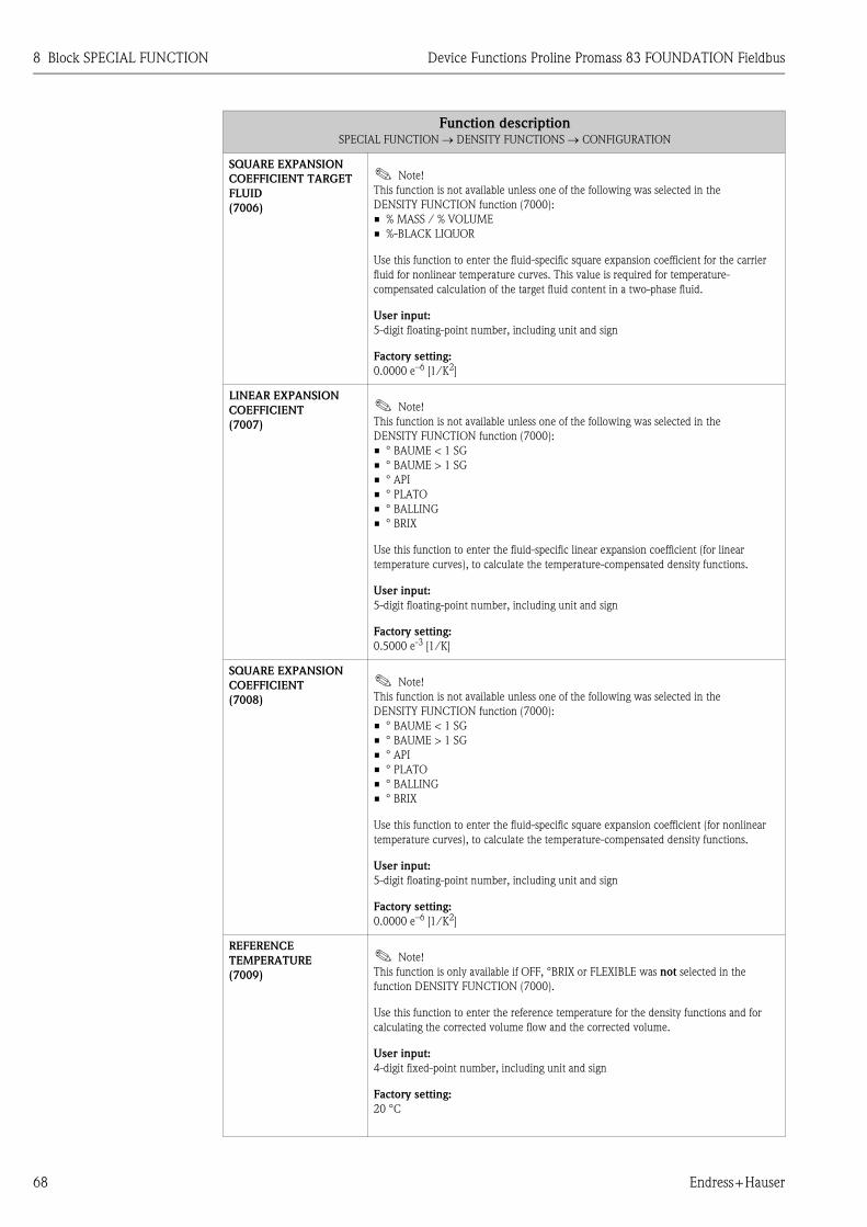
8 Block SPECIAL FUNCTION Device Functions Proline Promass 83 FOUNDATION Fieldbus
68 Endress+Hauser
SQUARE EXPANSION
COEFFICIENT TARGET
FLUID
(7006)
! Note!
This function is not available unless one of the following was selected in the
DENSITY FUNCTION function (7000):
• % MASS / % VOLUME
• %-BLACK LIQUOR
Use this function to enter the fluid-specific square expansion coefficient for the carrier
fluid for nonlinear temperature curves. This value is required for temperature-
compensated calculation of the target fluid content in a two-phase fluid.
User input:
5-digit floating-point number, including unit and sign
Factory setting:
0.0000 e–6 [1/K2]
LINEAR EXPANSION
COEFFICIENT
(7007)
! Note!
This function is not available unless one of the following was selected in the
DENSITY FUNCTION function (7000):
• ° BAUME < 1 SG
• ° BAUME > 1 SG
• ° API
• ° PLATO
• ° BALLING
• ° BRIX
Use this function to enter the fluid-specific linear expansion coefficient (for linear
temperature curves), to calculate the temperature-compensated density functions.
User input:
5-digit floating-point number, including unit and sign
Factory setting:
0.5000 e-3 [1/K]
SQUARE EXPANSION
COEFFICIENT
(7008)
! Note!
This function is not available unless one of the following was selected in the
DENSITY FUNCTION function (7000):
• ° BAUME < 1 SG
• ° BAUME > 1 SG
• ° API
• ° PLATO
• ° BALLING
• ° BRIX
Use this function to enter the fluid-specific square expansion coefficient (for nonlinear
temperature curves), to calculate the temperature-compensated density functions.
User input:
5-digit floating-point number, including unit and sign
Factory setting:
0.0000 e–6 [1/K2]
REFERENCE
TEMPERATURE
(7009)
! Note!
This function is only available if OFF, °BRIX or FLEXIBLE was not selected in the
function DENSITY FUNCTION (7000).
Use this function to enter the reference temperature for the density functions and for
calculating the corrected volume flow and the corrected volume.
User input:
4-digit fixed-point number, including unit and sign
Factory setting:
20 °C
Function descriptionSPECIAL FUNCTION → DENSITY FUNCTIONS → CONFIGURATION

Device Functions Proline Promass 83 FOUNDATION Fieldbus 8 Block SPECIAL FUNCTION
Endress+Hauser 69
MODE
(7021) ! Note!
This function is not available unless the FLEXIBLE setting was selected in the
DENSITY FUNCTION function (7000).
Use this function to select a user-specific method of calculating the concentration of the
density and temperature measured.
In order to use this function, the following values are required:
• Concentration (see formula)
• Currently measured density
• Currently measured temperature
The concentration is calculated from the density and temperature as follows:
K = A0 + A1 · ρ + A2 · ρ2 + A3 · ρ3 + A4 · ρ4 + B1 · T + B2 · T2 + B3 · T3
K = Concentration
ρ = Currently measured density
A0 = Value from function COEFFICIENT A0 (7032)
A1 = Value from function COEFFICIENT A1 (7033)
A2 = Value from function COEFFICIENT A2 (7034)
A3 = Value from function COEFFICIENT A3 (7035)
A4 = Value from function COEFFICIENT A4 (7036)
B1 = Value from function COEFFICIENT B1 (7037)
B2 = Value from function COEFFICIENT B2 (7038)
B3 = Value from function COEFFICIENT B3 (7039)
T = Currently measured temperature in °C
Options:
% MASS 3D
% VOLUME 3D
% MASS 2D
% VOLUME 2D
Factory setting:
% MASS 3D
! Note!
The relationship between the individual values (concentration, density and temperature)
can also be determined via the ToF Tool-Fieldtool Package operating program and be
transmitted to the measuring device.
Function descriptionSPECIAL FUNCTION → DENSITY FUNCTIONS → CONFIGURATION

8 Block SPECIAL FUNCTION Device Functions Proline Promass 83 FOUNDATION Fieldbus
70 Endress+Hauser
CONCENTRATION
SELECTOR
(7022)
Use this function to select a concentration specification. There are four different
concentration specifications available, via which various concentrations can be defined.
Options:
CONC. # 1 (or the name that has been defined in the function CONCENTRATION
NAME (7031) for concentration specification 1)
CONC. # 2 (or the name that has been defined in the function CONCENTRATION
NAME (7031) for concentration specification 2)
CONC. # 3 (or the name that has been defined in the function CONCENTRATION
NAME (7031) for concentration specification 3)
CONC. # 4 (or the name that has been defined in the function CONCENTRATION
NAME (7031) for concentration specification 4)
Factory setting:
CONC. # 1
! Note!
• By selecting a concentration specification and the (subsequent) relevant settings, up to
4 different concentrations can be preconfigured and selected when needed.
• All settings in the subsequent functions of this function group are each only valid for
the concentration specification selected in the function CONCENTRATION
SELECTOR (7022). In other words, the entry or option is assigned to the
concentration specification currently selected (e.g. in the factory setting CONC. # 1).
CONCENTRATION
NAME
(7031)
Use this function to assign a specific name to the concentration specification.
User input:
Max. 8-character text, permissible: A-Z, 0-9
Factory setting:
Name of concentration specification (depends on selection in the function
CONCENTRATION SELECTOR (7022), e.g. CONC. # 1).
COEFFICIENT A0
(7032)
Coefficient A0 entry.
User input:
5-digit floating-point number
Factory setting:
0
COEFFICIENT A1
(7033)
Coefficient A1 entry.
User input:
5-digit floating-point number
Factory setting:
0
COEFFICIENT A2
(7034)
Coefficient A2 entry.
User input:
5-digit floating-point number
Factory setting:
0
COEFFICIENT A3
(7035)
Coefficient A3 entry.
User input:
5-digit floating-point number
Factory setting:
0
Function descriptionSPECIAL FUNCTION → DENSITY FUNCTIONS → CONFIGURATION

Device Functions Proline Promass 83 FOUNDATION Fieldbus 8 Block SPECIAL FUNCTION
Endress+Hauser 71
COEFFICIENT A4
(7036)
Coefficient A4 entry.
User input:
5-digit floating-point number
Factory setting:
0
COEFFICIENT B1
(7037) ! Note!
This function only appears if the % MASS 3D or % VOLUME 3D option was selected in
the MODE function (7021).
Coefficient B1 entry.
User input:
5-digit floating-point number
Factory setting:
0
COEFFICIENT B2
(7038) ! Note!
This function only appears if the % MASS 3D or % VOLUME 3D option was selected in
the MODE function (7021).
Coefficient B2 entry.
User input:
5-digit floating-point number
Factory setting:
0
COEFFICIENT B3
(7039) ! Note!
This function only appears if the % MASS 3D or % VOLUME 3D option was selected in
the MODE function (7021).
Coefficient B3 entry.
User input:
5-digit floating-point number
Factory setting:
0
Function descriptionSPECIAL FUNCTION → DENSITY FUNCTIONS → CONFIGURATION

8 Block SPECIAL FUNCTION Device Functions Proline Promass 83 FOUNDATION Fieldbus
72 Endress+Hauser
8.2 Group ADVANCED DIAGNOSTICS
8.2.1 Function group CONFIGURATION
SPECIAL FUNCTION H ⇒ DENSITY FUNCTIONS HAA
⇓
ADVANCED DIAGNOSTICS HEA ⇒ CONFIGURATION 740
Function descriptionSPECIAL FUNCTION → ADVANCED DIAGNOSTICS → CONFIGURATION
REFERENCE
CONDITION USER
(7401)
Use this function to start determining the user reference status. The following values are
determined:
• MASS FLOW
• DENSITY
• REFERENCE DENSITY
• TEMPERATURE
• TUBE DAMPING
• ELECTRODYNAMIC SENSORS
• OPERATING FREQUENCY FLUCTUATION
• TUBE DAMPING FLUCTUATION
Options:
CANCEL
START
Factory setting:
CANCEL
SELECT REFERENCE
CONDITION
(7402)
Use this function to select the reference status which should be used to compare the
advanced diagnostics parameters (see function ACQUISITION MODE (7410)).
Options:
FACTORY
USER
Factory setting:
FACTORY
WARNING MODE
(7403)
Use this function to determine whether a warning should be generated when there
is a deviation between the reference status (FACTORY or USER, see function
SELECT REFERENCE CONDITION (7402)) and the current measuring values.
The values of the following functions are compared to the reference status :
• MASS FLOW (7421)
• DENSITY (7431)
• REFERENCE DENSITY (7441)
• TEMPERATURE (7451)
• TUBE DAMPING (7461)
• ELECTRODYNAMIC SENSORS (7471)
• OPERATING FREQUENCY FLUCTUATION (7481)
• TUBE DAMPING FLUCTUATION (7491)
Options:
OFF
ON
Factory setting:
OFF
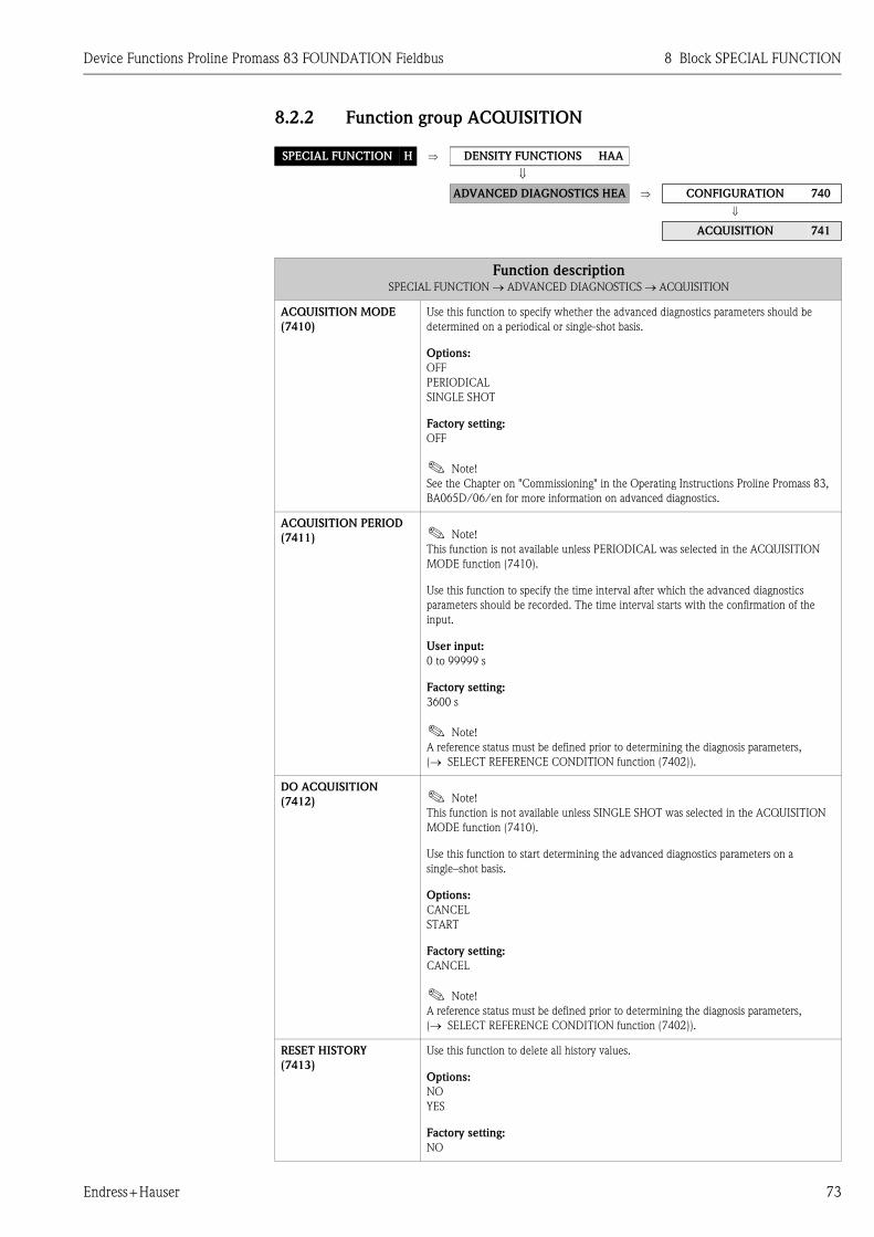
Device Functions Proline Promass 83 FOUNDATION Fieldbus 8 Block SPECIAL FUNCTION
Endress+Hauser 73
8.2.2 Function group ACQUISITION
SPECIAL FUNCTION H ⇒ DENSITY FUNCTIONS HAA
⇓
ADVANCED DIAGNOSTICS HEA ⇒ CONFIGURATION 740
⇓
ACQUISITION 741
Function descriptionSPECIAL FUNCTION → ADVANCED DIAGNOSTICS → ACQUISITION
ACQUISITION MODE
(7410)
Use this function to specify whether the advanced diagnostics parameters should be
determined on a periodical or single-shot basis.
Options:
OFF
PERIODICAL
SINGLE SHOT
Factory setting:
OFF
! Note!
See the Chapter on "Commissioning" in the Operating Instructions Proline Promass 83,
BA065D/06/en for more information on advanced diagnostics.
ACQUISITION PERIOD
(7411) ! Note!
This function is not available unless PERIODICAL was selected in the ACQUISITION
MODE function (7410).
Use this function to specify the time interval after which the advanced diagnostics
parameters should be recorded. The time interval starts with the confirmation of the
input.
User input:
0 to 99999 s
Factory setting:
3600 s
! Note!
A reference status must be defined prior to determining the diagnosis parameters,
(→ SELECT REFERENCE CONDITION function (7402)).
DO ACQUISITION
(7412) ! Note!
This function is not available unless SINGLE SHOT was selected in the ACQUISITION
MODE function (7410).
Use this function to start determining the advanced diagnostics parameters on a
single–shot basis.
Options:
CANCEL
START
Factory setting:
CANCEL
! Note!
A reference status must be defined prior to determining the diagnosis parameters,
(→ SELECT REFERENCE CONDITION function (7402)).
RESET HISTORY
(7413)
Use this function to delete all history values.
Options:
NO
YES
Factory setting:
NO

8 Block SPECIAL FUNCTION Device Functions Proline Promass 83 FOUNDATION Fieldbus
74 Endress+Hauser
8.2.3 Function group MASS FLOW
SPECIAL FUNCTION H ⇒ DENSITY FUNCTIONS HAA
⇓
ADVANCED DIAGNOSTICS HEA ⇒ CONFIGURATION 740
⇓
ACQUISITION 741
⇓
MASS FLOW 742
Function descriptionSPECIAL FUNCTION → ADVANCED DIAGNOSTICS → MASS FLOW
! Note!
The appropriate unit is taken from the UNIT MASS FLOW function (0400).
REFERENCE VALUE
MASS FLOW
(7420)
The reference value for the mass flow appears on the display.
Display:
5-digit floating-point number, including unit and sign
MASS FLOW
(7421)
The measured mass flow appears on the display.
Display:
5-digit floating-point number, including unit and sign
MINIMUM MASS FLOW
(7422)
The lowest mass flow value since the saved values were last reset appears on the display.
Display:
5-digit floating-point number, including unit and sign
MAXIMUM MASS FLOW
(7423)
The highest mass flow value since the saved values were last reset appears on the display.
Display:
5-digit floating-point number, including unit and sign
HISTORY MASS FLOW
(7424)
The last ten mass flow values since the saved values were last reset appear on the display.
Display:
5-digit floating-point number, including unit and sign
DEVIATION MASS FLOW
(7425)
This function displays the deviation between the measured mass flow and the reference
values (FACTORY or USER) selected in the function SELECT REFERENCE CONDITION
(7402).
Display:
5-digit floating-point number, including unit and sign
WARNING LEVEL
(7426) ! Note!
This function is not available unless ON was selected in the WARNING MODE function
(7403).
Use this function to specify a limit value for the mass flow. A notice message is generated
if the limit value is exceeded.
User input:
0 to 99999 [mass flow unit]
Factory setting:
90000 kg/h

Device Functions Proline Promass 83 FOUNDATION Fieldbus 8 Block SPECIAL FUNCTION
Endress+Hauser 75
8.2.4 Function group DENSITY
SPECIAL FUNCTION H ⇒ DENSITY FUNCTIONS HAA
⇓
ADVANCED DIAGNOSTICS HEA ⇒ CONFIGURATION 740
⇓
ACQUISITION 741
⇓
MASS FLOW 742
⇓
DENSITY 743
Function descriptionSPECIAL FUNCTION → ADVANCED DIAGNOSTICS → DENSITY
! Note!
The appropriate unit is taken from the UNIT DENSITY function (0420).
REFERENCE VALUE
DENSITY
(7430)
The reference value for the density appears on the display.
Display:
5-digit floating-point number, incl. units
DENSITY
(7431)
The measured density appears on the display.
Display:
5-digit floating-point number, incl. units
MINIMUM DENSITY
(7432)
The lowest density value since the saved values were last reset appears on the display.
Display:
5-digit floating-point number, incl. units
MAXIMUM DENSITY
(7433)
The highest density value since the saved values were last reset appears on the display.
Display:
5-digit floating-point number, incl. units
HISTORY DENSITY
(7434)
The last ten density values since the saved values were last reset appear on the display.
Display:
5-digit floating-point number, incl. units
DEVIATION DENSITY
(7435)
This function displays the deviation between the measured density and the reference
values (FACTORY or USER) selected in the function SELECT REFERENCE CONDITION
(7402).
Display:
5-digit floating-point number, incl. units
WARNING LEVEL
(7436) ! Note!
This function is not available unless ON was selected in the WARNING MODE function
(7403).
Use this function to specify a limit value for the density. A notice message is generated if
the limit value is exceeded.
User input:
0 to 99999 [%]
Factory setting:
100%

8 Block SPECIAL FUNCTION Device Functions Proline Promass 83 FOUNDATION Fieldbus
76 Endress+Hauser
8.2.5 Function group REFERENCE DENSITY
SPECIAL FUNCTION H ⇒ DENSITY FUNCTIONS HAA
⇓
ADVANCED DIAGNOSTICS HEA ⇒ CONFIGURATION 740
⇓
ACQUISITION 741
⇓
MASS FLOW 742
⇓
DENSITY 743
⇓
REFERENCE DENSITY 744
Function descriptionSPECIAL FUNCTION → ADVANCED DIAGNOSTICS → REFERENCE DENSITY
! Note!
The appropriate unit is taken from the function UNIT REFERENCE DENSITY (0421) ( → Page 17).
REFERENCE VALUE
REFERENCE DENSITY
(7440)
The reference value for the reference density appears on the display.
Display:
5-digit floating-point number, incl. units
REFERENCE DENSITY
(7441)
The measured reference density appears on the display.
Display:
5-digit floating-point number, incl. units
MINIMUM
REFERENCE DENSITY
(7442)
The lowest reference density value since the saved values were last reset appears on the
display.
Display:
5-digit floating-point number, incl. units
MAXIMUM
REFERENCE DENSITY
(7443)
The highest reference density value since the saved values were last reset appears on the
display.
Display:
5-digit floating-point number, incl. units
HISTORY
REFERENCE DENSITY
(7444)
The last ten reference density values since the saved values were last reset appear on the
display.
Display:
5-digit floating-point number, incl. units
DEVIATION
REFERENCE DENSITY
(7445)
This function displays the deviation between the measured reference density and the
reference values (FACTORY or USER) selected in the function SELECT REFERENCE
CONDITION (7402).
Display:
5-digit floating-point number, incl. units
WARNING LEVEL
(7446) ! Note!
This function is not available unless ON was selected in the WARNING MODE function
(7403).
Use this function to specify a limit value for the reference density. A notice message is
generated if the limit value is exceeded.
User input:
0 to 99999 [%]
Factory setting:
100%

Device Functions Proline Promass 83 FOUNDATION Fieldbus 8 Block SPECIAL FUNCTION
Endress+Hauser 77
8.2.6 Function group TEMPERATURE
SPECIAL FUNCTION H ⇒ DENSITY FUNCTIONS HAA
⇓
ADVANCED DIAGNOSTICS HEA ⇒ CONFIGURATION 740
⇓
ACQUISITION 741
⇓
MASS FLOW 742
⇓
DENSITY 743
⇓
REFERENCE DENSITY 744
⇓
TEMPERATURE 745
Function descriptionSPECIAL FUNCTION → ADVANCED DIAGNOSTICS → TEMPERATURE
! Note!
The appropriate unit is taken from the UNIT TEMPERATURE function (0422).
REFERENCE VALUE
TEMPERATURE
(7450)
The reference value for the temperature appears on the display.
Display:
5-digit floating-point number, including unit and sign
TEMPERATURE
(7451)
The currently measured temperature appears on the display.
Display:
5-digit floating-point number, including unit and sign
MINIMUM
TEMPERATURE
(7452)
The lowest temperature value since the saved values were last reset appears on the
display.
Display:
5-digit floating-point number, including unit and sign
MAXIMUM
TEMPERATURE
(7453)
The highest temperature value since the saved values were last reset appears on the
display.
Display:
5-digit floating-point number, including unit and sign
HISTORY TEMPERATURE
(7454)
The last ten temperature values since the saved values were last reset appear on the
display.
Display:
5-digit floating-point number, including unit and sign
DEVIATION
TEMPERATURE
(7455)
This function displays the deviation between the currently measured temperature and the
reference values (FACTORY or USER) selected in the function SELECT REFERENCE
CONDITION (7402).
Display:
5-digit floating-point number, including unit and sign
WARNING LEVEL
(7456) ! Note!
This function is not available unless ON was selected in the WARNING MODE function
(7403).
Use this function to specify a limit value for the temperature. A notice message is
generated if the limit value is exceeded.
User input:
0 to 99999 °C
Factory setting:
100 °C

8 Block SPECIAL FUNCTION Device Functions Proline Promass 83 FOUNDATION Fieldbus
78 Endress+Hauser
8.2.7 Function group TUBE DAMPING
SPECIAL FUNCTION H ⇒ DENSITY FUNCTIONS HAA
⇓
ADVANCED DIAGNOSTICS HEA ⇒ CONFIGURATION 740
⇓
ACQUISITION 741
⇓
MASS FLOW 742
⇓
DENSITY 743
⇓
REFERENCE DENSITY 744
⇓
TEMPERATURE 745
⇓
TUBE DAMPING 746
Function descriptionSPECIAL FUNCTION → ADVANCED DIAGNOSTICS → TUBE DAMPING
REFERENCE VALUE
TUBE DAMPING
(7460)
The reference value for tube damping appears on the display.
Display:
5-digit floating-point number
TUBE DAMPING
(7461)
The measured tube damping appears on the display.
Display:
5-digit floating-point number
MINIMUM
TUBE DAMPING
(7462)
The lowest tube damping value since the saved values were last reset appears on the
display.
Display:
5-digit floating-point number
MAXIMUM
TUBE DAMPING
(7463)
The highest tube damping value since the saved values were last reset appears on the
display.
Display:
5-digit floating-point number
HISTORY
TUBE DAMPING
(7464)
The last ten tube damping values since the saved values were last reset appears on the
display.
Display:
5-digit floating-point number
DEVIATION
TUBE DAMPING
(7465)
This function displays the deviation between the measured tube damping and the
reference values (FACTORY or USER) selected in the function SELECT REFERENCE
CONDITION (7402).
Display:
5-digit floating-point number
WARNING LEVEL
(7466) ! Note!
This function is not available unless ON was selected in the WARNING MODE function
(7403).
Use this function to specify a limit value for tube damping. A notice message is generated
if the limit value is exceeded.
User input:
0 to 99999%
Factory setting:
1000%

Device Functions Proline Promass 83 FOUNDATION Fieldbus 8 Block SPECIAL FUNCTION
Endress+Hauser 79
8.2.8 Function group ELECTRODYNAMIC SENSORS
SPECIAL FUNCTION H ⇒ DENSITY FUNCTIONS HAA
⇓
ADVANCED DIAGNOSTICS HEA ⇒ CONFIGURATION 740
⇓
ACQUISITION 741
⇓
MASS FLOW 742
⇓
DENSITY 743
⇓
REFERENCE DENSITY 744
⇓
TEMPERATURE 745
⇓
TUBE DAMPING 746
⇓
ELEC.-DYN. SENSORS 747
Function descriptionSPECIAL FUNCTION → ADVANCED DIAGNOSTICS → ELECTRODYNAMIC SENSORS
REFERENCE VALUE
ELECTRODYNAMIC
SENSORS
(7470)
The reference value for the electrodynamic sensors appears on the display.
Display:
5-digit floating-point number
ELECTRODYNAMIC
SENSORS
(7471)
The measuring values for the electrodynamic sensors appear on the display.
Display:
5-digit floating-point number
MINIMUM
ELECTRODYNAMIC
SENSORS
(7472)
The lowest value of the electrodynamic sensors since the saved values were last reset
appears on the display.
Display:
5-digit floating-point number
MAXIMUM
ELECTRODYNAMIC
SENSORS
(7473)
The highest value of the electrodynamic sensors since the saved values were last reset
appears on the display.
Display:
5-digit floating-point number
HISTORY
ELECTRODYNAMIC
SENSOR
(7474)
The last ten values of the electrodynamic sensors since the saved values were last reset
appear on the display.
Display:
5-digit floating-point number
DEVIATION
ELECTRODYNAMIC
SENSOR
(7475)
This function displays the deviation between the measured values for the electrodynamic
sensors and the reference values (FACTORY or USER) selected in the function
SELECT REFERENCE CONDITION (7402).
Display:
5-digit floating-point number

8 Block SPECIAL FUNCTION Device Functions Proline Promass 83 FOUNDATION Fieldbus
80 Endress+Hauser
8.2.9 Function group OPERATING FREQUENCY FLUCTUATION
WARNING LEVEL
(7476) ! Note!
This function is not available unless ON was selected in the WARNING MODE function
(7403).
Use this function to specify a limit value for the electrodynamic sensors. A notice message
is generated if the limit value is exceeded.
User input:
0 to 99999%
Factory setting:
100%
SPECIAL FUNCTION H ⇒ DENSITY FUNCTIONS HAA
⇓
ADVANCED DIAGNOSTICS HEA ⇒ CONFIGURATION 740
⇓
ACQUISITION 741
⇓
MASS FLOW 742
⇓
DENSITY 743
⇓
REFERENCE DENSITY 744
⇓
TEMPERATURE 745
⇓
TUBE DAMPING 746
⇓
ELEC.-DYN. SENSORS 747
⇓
OPERATING FREQ.
FLUCT.
748
Function descriptionSPECIAL FUNCTION → ADVANCED DIAGNOSTICS → OPERATING FREQUENCY FLUCTUATION
REFERENCE VALUE
OPERATING
FREQUENCY
FLUCTUATION
(7480)
The reference value for the fluctuation of the operating frequency appears on the display.
Display:
5-digit floating-point number, Hz
OPERATING
FREQUENCY
FLUCTUATION
(7481)
The measured fluctuation of the operating frequency appears on the display.
Display:
5-digit floating-point number, Hz
MINIMUM
OPERATING
FREQUENCY
FLUCTUATION
(7482)
The lowest value of the operating frequency fluctuation since the saved values were last
reset appears on the display.
Display:
5-digit floating-point number, Hz
MAXIMUM
OPERATING
FREQUENCY
FLUCTUATION
(7483)
The highest value of the operating frequency fluctuation since the saved values were last
reset appears on the display.
Display:
5-digit floating-point number, Hz
Function descriptionSPECIAL FUNCTION → ADVANCED DIAGNOSTICS → ELECTRODYNAMIC SENSORS

Device Functions Proline Promass 83 FOUNDATION Fieldbus 8 Block SPECIAL FUNCTION
Endress+Hauser 81
8.2.10 Function group TUBE DAMPING FLUCTUATION
HISTORY
OPERATING
FREQUENCY
FLUCTUATION
(7484)
The last ten values of the operating frequency fluctuation since the saved values were last
reset appear on the display.
Display:
5-digit floating-point number, Hz
DEVIATION
OPERATING
FREQUENCY
FLUCTUATION
(7485)
This function displays the deviation between the measured fluctuation of the operating
frequency and the reference values (FACTORY or USER) selected in the function
SELECT REFERENCE CONDITION (7402).
Display:
5-digit floating-point number, Hz
WARNING LEVEL
(7486) ! Note!
This function is not available unless ON was selected in the WARNING MODE function
(7403).
Use this function to specify a limit value for the operating frequency fluctuation. A notice
message is generated if the limit value is exceeded.
User input:
0 to 99999 Hz
Factory setting:
1000 Hz
SPECIAL FUNCTION H ⇒ DENSITY FUNCTIONS HAA
⇓
ADVANCED DIAGNOSTICS HEA ⇒ CONFIGURATION 740
⇓
ACQUISITION 741
⇓
MASS FLOW 742
⇓
DENSITY 743
⇓
REFERENCE DENSITY 744
⇓
TEMPERATURE 745
⇓
TUBE DAMPING 746
⇓
ELEC.-DYN. SENSORS 747
⇓
OPERATING FREQ. FLUCT. 748
⇓
TUBE DAMP. FLUCT. 749
Function descriptionSPECIAL FUNCTION → ADVANCED DIAGNOSTICS → TUBE DAMPING FLUCTUATION
REFERENCE VALUE
TUBE DAMPING
FLUCTUATION
(7490)
The reference value for the fluctuation of the tube damping appears on the display.
Display:
5-digit floating-point number
Function descriptionSPECIAL FUNCTION → ADVANCED DIAGNOSTICS → OPERATING FREQUENCY FLUCTUATION

8 Block SPECIAL FUNCTION Device Functions Proline Promass 83 FOUNDATION Fieldbus
82 Endress+Hauser
TUBE DAMPING
FLUCTUATION
(7491)
The measured fluctuation of the tube damping appears on the display.
Display:
5-digit floating-point number
MINIMUM
TUBE DAMPING
FLUCTUATION
(7492)
The lowest value of the tube damping since the saved values were last reset appears on
the display.
Display:
5-digit floating-point number
MAXIMUM
TUBE DAMPING
FLUCTUATION
(7493)
The highest value of the tube damping fluctuation since the saved values were last reset
appears on the display.
Display:
5-digit floating-point number
HISTORY TUBE
DAMPING
FLUCTUATION
(7494)
The last ten values of the tube damping fluctuation since the saved values were last reset
appear on the display.
Display:
5-digit floating-point number
DEVIATION
TUBE DAMPING
FLUCTUATION
(7495)
This function displays the deviation between the measured fluctuation of the tube
damping and the reference values (FACTORY or USER) selected in the function
SELECT REFERENCE CONDITION (7402).
Display:
5-digit floating-point number
WARNING LEVEL
(7496) ! Note!
This function is not available unless ON was selected in the WARNING MODE function
(7403).
Use this function to specify a limit value for the tube damping fluctuation. A notice
message is generated if the limit value is exceeded.
User input:
0 to 99999
Factory setting:
1000
Function descriptionSPECIAL FUNCTION → ADVANCED DIAGNOSTICS → TUBE DAMPING FLUCTUATION

Device Functions Proline Promass 83 FOUNDATION Fieldbus 9 Block SUPERVISION
Endress+Hauser 83
9 Block SUPERVISION
Fun
cti
on
s
OPE
RA
TIO
N
HO
UR
S
(80
48
) P
.8
6
SY
ST
EM
RE
SE
T
(80
46
) P
.8
6
VA
LU
E S
IM.
ME
ASU
R.
(80
44
) P
.8
6
SIM
.
ME
ASU
RA
ND
(80
43
) P
.8
5
ST
OR
AG
E
(80
07
) P
.8
4
SIM
. FA
ILSA
FE
MO
DE
(80
42
) P
.8
5
SW
RE
V. N
O.
S-D
AT
(82
05
) P
.8
7
LA
NG
UA
GE
GR
OU
P
(82
26
) P
.8
8
SW
RE
V. N
O
F-C
HIP
(82
44
) P
.8
9
RE
MO
VE
SW
-OPT
ION
(80
06
) P
.8
4
PR
EV
. SY
S.
CO
ND
ITIO
N
(80
41
) P
.8
5
SE
NSO
R T
YPE
(82
01
) P
.8
7
SW
RE
V.
NO
.
T-D
AT
(82
25
) P
.8
8
SY
ST
EM
OPT
ION
(82
41
) P
.8
9
SW
RE
V.-
NO
.
I/O
MO
DU
LE
(83
03
) P
.8
9
⇒ ⇒ ⇒ ⇒ ⇒ ⇒
ALA
RM
DE
LA
Y
(80
05
) P
.8
4
AC
T. SY
S.
CO
ND
ITIO
N
(80
40
) P
.8
5
DE
VIC
E
SO
FT
WA
RE
(81
00
) P
.8
7
SE
RIA
L N
UM
BE
R
(82
00
) P
.8
7
SW
RE
V. N
O.
AM
PLIF
IER
(82
22
) P
.8
8
ST
AT
US F
-CH
IP
(82
40
) P
.8
8
I/O
MO
DU
LE
TY
PE
(83
00
) P
.8
9
⇒ ⇒ ⇒ ⇒ ⇒ ⇒ ⇒
Fu
ncti
on
gro
ups
CO
NFIG
UR
AT
ION
(80
0)
P.8
4
⇒⇐
OPE
RA
TIO
N
(80
4)
P.8
7
DE
VIC
E
(81
0)
P.8
7
⇒⇐
SE
NSO
R
(82
0)
P.8
7
⇒⇐
AM
PLIF
IER
(82
2)
P.8
8
⇒⇐
F-C
HIP
(82
4)
P.8
8
⇒⇐
I/O
MO
DU
LE
(83
0)
P.8
9
⇒ ⇒
Gro
up
s
SY
ST
EM
(JA
A)
P.8
4
⇒⇐
⇒⇐
VE
RSIO
N I
NFO
(JC
A)
P.87
⇒
Blo
ck
SU
PE
RV
ISIO
N
(J)

9 Block SUPERVISION Device Functions Proline Promass 83 FOUNDATION Fieldbus
84 Endress+Hauser
9.1 Group SYSTEM
9.1.1 Function group CONFIGURATION
SUPERVISION J ⇒ SYSTEM JAA ⇒ CONFIGURATION 800
Function descriptionSUPERVISION → SYSTEM → CONFIGURATION
ALARM DELAY
(8005)
Use this function to define a time span for which the criteria for an error have to be
satisfied without interruption before a fault or notice message is generated.
Depending on the setting and the type of error, this suppression acts on:
• Display
• FOUNDATION Fieldbus
User input:
0 to 100 s (in steps of one second)
Factory setting:
0 s
" Caution!
If this function is activated, fault and notice messages are delayed by the time
corresponding to the setting before being transmitted to the higher-order controller
(process controller, etc.). It is therefore imperative to check in advance in order to make
sure whether a delay of this nature could affect the safety requirements of the process. If
fault and notice messages may not be suppressed, a value of 0 seconds must be entered
here.
REMOVE
SW-OPTION
(8006)
! Note!
This function is only available if:
• The F-CHIP software options were saved beforehand
• The F-CHIP is not located on the I/O board of the measuring device
Deletes all F-CHIP software options, such as batching, density functions, etc.
Options:
NO
YES
Factory setting:
NO
" Caution!
If process variables which are only available via the F-CHIP software options are assigned
to the local display or the outputs, these have to be reconfigured. If reconfiguration does
not take place, the local display and the totalizer are set to the factory setting and the
outputs are set to OFF.
PERMANENT STORAGE
(8007)
This function indicates whether automatic, permanent storage of parameter changes in
the EEPROM is switched on or off.
Display:
OFF
ON
Factory setting:
ON
" Caution!
• The selection for this function can only be changed by the Endress+Hauser service
organization.
• If OFF is selected, all parameter changes are not permanently stored in the EEPROM.
This means that these parameter changes are no longer available after a power failure.
In these instances, the device starts with the parameter configurations last stored in
the EEPROM.

Device Functions Proline Promass 83 FOUNDATION Fieldbus 9 Block SUPERVISION
Endress+Hauser 85
9.1.2 Function group OPERATION
SUPERVISION J ⇒ SYSTEM JAA ⇒ CONFIGURATION 800
⇓
OPERATION 804
Function descriptionSUPERVISION → SYSTEM → OPERATION
ACTUAL
SYSTEM CONDITION
(8040)
Use this function to check the present system status.
Display:
SYSTEM OK
or
The fault/notice message with the highest priority.
PREVIOUS SYSTEM
CONDITION
(8041)
Use this function to view the fifteen most recent error and notice messages since
measuring last started.
Display:
The 15 most recent error or notice messages.
SIMULATION FAILSAFE
MODE
(8042)
Use this function to set all inputs, outputs and totalizers to their defined failsafe modes, in
order to check whether they respond correctly. During this time, the words
"SIMULATION FAILSAFE MODE" appear on the display.
Options:
ON
OFF
Factory setting:
OFF
! Note!
With the fieldbus, an active simulation is relayed to downstream function blocks or
higher-level process control systems by means of the status "UNCERTAIN" of the output
value OUT (AI Block).
SIMULATION
MEASURAND
(8043)
Use this function to set all inputs, outputs and totalizers to their defined flow-response
modes, in order to check whether they respond correctly. During this time, the words
"SIMULATION MEASURAND" appear on the display.
Options:
OFF
MASS FLOW
VOLUME FLOW
CORRECTED VOLUME FLOW
DENSITY
REFERENCE DENSITY
TEMPERATURE
Factory setting:
OFF
" Caution!
• The measuring device cannot be used for measuring while this simulation is in
progress.
• The setting is not saved if the power supply fails.
! Note!
• An active simulation of the measurand is communicated to the subsequent function
blocks via the status "UNCERTAIN" for the process variables.
• The simulation is independent of the position of the jumper for the simulation mode
on the I/O board.

9 Block SUPERVISION Device Functions Proline Promass 83 FOUNDATION Fieldbus
86 Endress+Hauser
VALUE SIMULATION
MEASURAND
(8044)
! Note!
The function is not visible unless the SIMULATION MEASURAND function (8043) is
active.
Use this function to define a selectable value (e.g. 12 m3/s). This is used to test the
associated functions in the device itself and downstream signal loops.
User input:
5-digit floating-point number [unit]
Factory setting:
0 [unit]
" Caution!
• The setting is not saved if the power supply fails.
• The appropriate unit is taken from the SYSTEM UNITS group (ACA) ( → Page 14).
SYSTEM RESET
(8046)
Use this function to perform a reset of the measuring system.
Options:
NO
RESTART SYSTEM (restart without interrupting power supply)
Factory setting:
NO
OPERATION HOURS
(8048)
Use this function to read the operating hours of the measuring device.
Display:
Depends on the number of hours of operation elapsed:
Hours of operation < 10 hours → display format = 0:00:00 (hr:min:sec)
Hours of operation 10 to 10000 hours → display format = 0000:00 (hr:min)
Hours of operation > 10000 hours → display format = 000000 (hr)
Function descriptionSUPERVISION → SYSTEM → OPERATION

Device Functions Proline Promass 83 FOUNDATION Fieldbus 9 Block SUPERVISION
Endress+Hauser 87
9.2 Group VERSION INFO
9.2.1 Function group DEVICE
9.2.2 Function group SENSOR
SUPERVISION J ⇒ SYSTEM JAA
⇓
VERSION INFO JCA ⇒ DEVICE 810
Function descriptionSUPERVISION → VERSION INFO → DEVICE
DEVICE SOFTWARE
(8100)
Displays the current device software version.
SUPERVISION J ⇒ SYSTEM JAA
⇓
VERSION INFO JCA ⇒ DEVICE 810
⇓
SENSOR 820
Function descriptionSUPERVISION → VERSION INFO → SENSOR
SERIAL NUMBER
(8200)
Use this function to view the serial number of the sensor.
SENSOR TYPE
(8201)
Use this function to view the sensor type (e.g. Promass F).
SOFTWARE
REVISION NUMBER
S-DAT
(8205)
Use this function to view the software revision number of the software used to create the
content of the S-DAT.

9 Block SUPERVISION Device Functions Proline Promass 83 FOUNDATION Fieldbus
88 Endress+Hauser
9.2.3 Function group AMPLIFIER
9.2.4 Function group F-CHIP
SUPERVISION J ⇒ SYSTEM JAA
⇓
VERSION INFO JCA ⇒ DEVICE 810
⇓
SENSOR 820
⇓
AMPLIFIER 822
Function descriptionSUPERVISION → VERSION INFO → AMPLIFIER
SOFTWARE REVISION
NUMBER AMPLIFIER
(8222)
Use this function to view the software revision number of the amplifier.
SOFTWARE
REVISION NUMBER
T-DAT
(8225)
Use this parameter to view the software revision number of the software used to create
the content of the T-DAT.
LANGUAGE GROUP
(8226)
Use this function to view the language group installed.
The following language groups can be ordered: WEST EU / USA, EAST EU / SCAND.,
ASIA , CHINA.
Display:
available language group
! Note!
• The language options of the available language group are displayed in the LANGUAGE
(2000) function.
• You can change the language group via the configuration software ToF Tool-Fieldtool
Package. Please do not hesitate to contact your Endress+Hauser sales office if you have
any questions.
SUPERVISION J ⇒ SYSTEM JAA
⇓
VERSION INFO JCA ⇒ DEVICE 810
⇓
SENSOR 820
⇓
AMPLIFIER 822
⇓
F-CHIP 824
Function descriptionSUPERVISION → VERSION INFO → F-CHIP
STATUS F-CHIP
(8240)
Use this function to check whether an F-CHIP is installed and which software options are
available.

Device Functions Proline Promass 83 FOUNDATION Fieldbus 9 Block SUPERVISION
Endress+Hauser 89
9.2.5 Function group I/O MODULE
SYSTEM OPTION
(8241) ! Note!
This function is not available unless the measuring device is equipped an F-CHIP.
The software options available in the measuring device appear on the display.
Display:
NO ENTRY (= no SW options available)
ADVANCED DIAGNOSTICS
DENSITY FUNCTIONS
SOFTWARE
REVISION NUMBER
F-CHIP
(8244)
! Note!
The F-CHIP must be available in order to access this function.
Use this function to view the software revision number of the F-CHIP.
SUPERVISION J ⇒ SYSTEM JAA
⇓
VERSION INFO JCA ⇒ SENSOR 820
⇓
AMPLIFIER 822
⇓
I/O MODULE 830
Function descriptionSUPERVISION → VERSION INFO → I/O MODULE
I/O MODULE TYPE
(8300)
Use this function to view the configuration of the I/O module complete with terminal
numbers.
SOFTWARE
REVISION NUMBER
I/O MODULE
(8303)
Use this function to view the software revision number of the I/O module.
Function descriptionSUPERVISION → VERSION INFO → F-CHIP

10 Factory settings Device Functions Proline Promass 83 FOUNDATION Fieldbus
90 Endress+Hauser
10 Factory settings
10.1 SI units (not for USA and Canada)
10.1.1 Low flow cut off, full scale value, pulse value
10.1.2 Language
Nominal diameter Low flow cut off Full scale value
[mm] (approx. v = 0.04 m/s) (approx. v = 2.0 m/s)
1 0.08 kg/h 4 kg/h
2 0.40 kg/h 20 kg/h
4 1.80 kg/h 90 kg/h
8 8.00 kg/h 400 kg/h
15 26.00 kg/h 1300 kg/h
15 FB 72.00 kg/h 3600 kg/h
25 72.00 kg/h 3600 kg/h
25 FB 180.00 kg/h 9000 kg/h
40 180.00 kg/h 9000 kg/h
40 FB 300.00 kg/h 15000 kg/h
50 300.00 kg/h 15000 kg/h
50 FB 720.00 kg/h 36000 kg/h
80 720.00 kg/h 36000 kg/h
100 1200.00 kg/h 60000 kg/h
150 2600.00 kg/h 130000 kg/h
250 7200.00 kg/h 360000 kg/h
FB = Full bore versions of Promass I
Country Language
Australia English
Belgium English
China Chinese
Denmark English
Germany Deutsch
England English
Finland Suomi
France Francais
Netherlands Nederlands
Hong Kong English
India English
Indonesia Bahasa Indonesia
Instruments International English
Italy Italiano
Japan Japanese
Malaysia English
Norway Norsk
Poland Polish
Portugal Portuguese
Austria Deutsch
Russia Russian
Sweden Svenska
Switzerland Deutsch
Singapore English
Spain Espanol
South Africa English
Thailand English
Czech Republic Czech
Hungary English
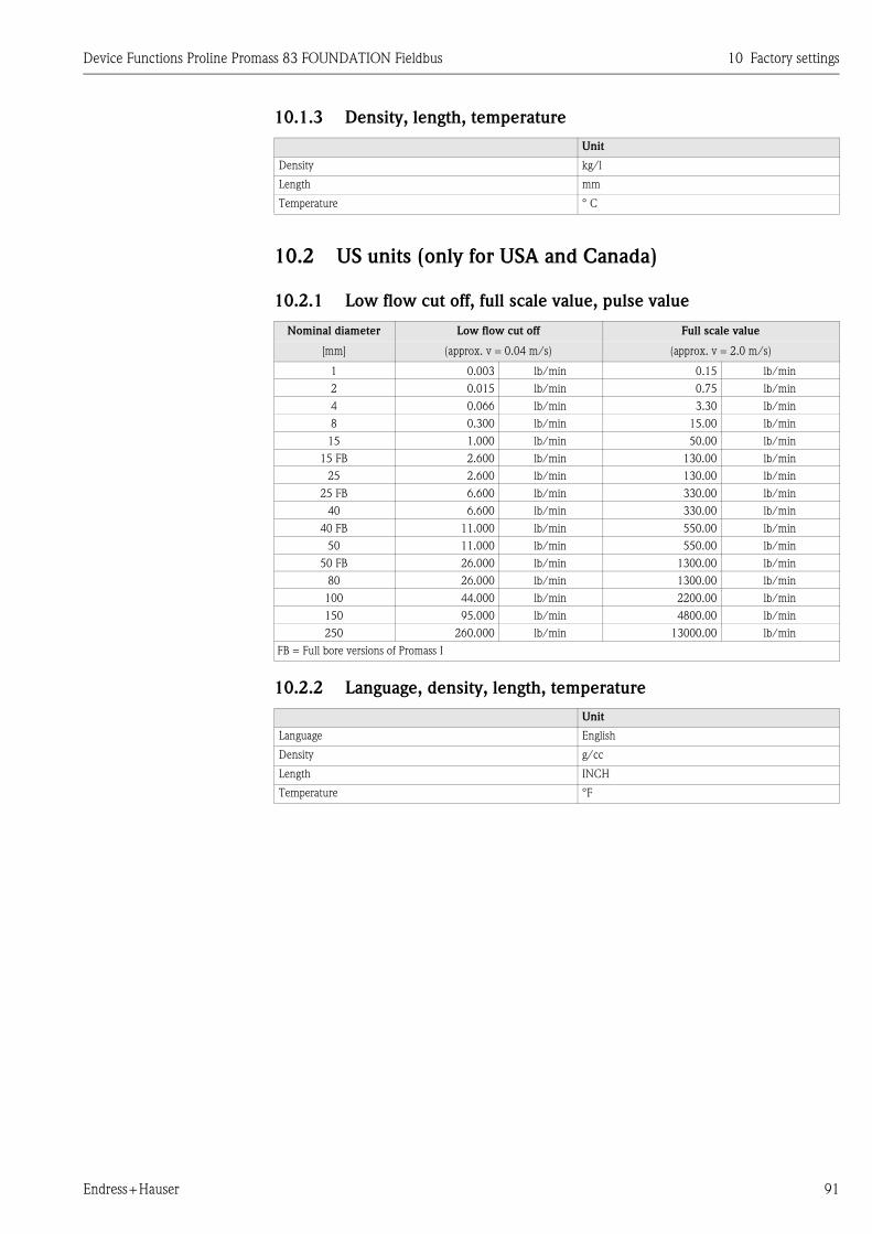
Device Functions Proline Promass 83 FOUNDATION Fieldbus 10 Factory settings
Endress+Hauser 91
10.1.3 Density, length, temperature
10.2 US units (only for USA and Canada)
10.2.1 Low flow cut off, full scale value, pulse value
10.2.2 Language, density, length, temperature
Unit
Density kg/l
Length mm
Temperature ° C
Nominal diameter Low flow cut off Full scale value
[mm] (approx. v = 0.04 m/s) (approx. v = 2.0 m/s)
1 0.003 lb/min 0.15 lb/min
2 0.015 lb/min 0.75 lb/min
4 0.066 lb/min 3.30 lb/min
8 0.300 lb/min 15.00 lb/min
15 1.000 lb/min 50.00 lb/min
15 FB 2.600 lb/min 130.00 lb/min
25 2.600 lb/min 130.00 lb/min
25 FB 6.600 lb/min 330.00 lb/min
40 6.600 lb/min 330.00 lb/min
40 FB 11.000 lb/min 550.00 lb/min
50 11.000 lb/min 550.00 lb/min
50 FB 26.000 lb/min 1300.00 lb/min
80 26.000 lb/min 1300.00 lb/min
100 44.000 lb/min 2200.00 lb/min
150 95.000 lb/min 4800.00 lb/min
250 260.000 lb/min 13000.00 lb/min
FB = Full bore versions of Promass I
Unit
Language English
Density g/cc
Length INCH
Temperature °F

10 Factory settings Device Functions Proline Promass 83 FOUNDATION Fieldbus
92 Endress+Hauser

Device Functions Proline Promass 83 FOUNDATION Fieldbus 11 Index Function matrix
Endress+Hauser 93
11 Index Function matrix
BlocksA = MEASURED VARIABLES . . . . . . . . . . . . . . . . . . . . . . . 9
B = QUICK SETUP . . . . . . . . . . . . . . . . . . . . . . . . . . . . . 19
C = USER INTERFACE . . . . . . . . . . . . . . . . . . . . . . . . . . 22
D = TOTALIZER . . . . . . . . . . . . . . . . . . . . . . . . . . . . . . . 43
G = BASIC FUNCTION . . . . . . . . . . . . . . . . . . . . . . . . . . 48
H = SPECIAL FUNCTION . . . . . . . . . . . . . . . . . . . . . . . . 65
J = SUPERVISION . . . . . . . . . . . . . . . . . . . . . . . . . . . . . . 83
GroupsAAA = MEASURING VALUES . . . . . . . . . . . . . . . . . . . . . 10
ACA = SYSTEM UNITS . . . . . . . . . . . . . . . . . . . . . . . . . . 14
CAA = CONTROL . . . . . . . . . . . . . . . . . . . . . . . . . . . . . . 23
CCA = MAIN LINE . . . . . . . . . . . . . . . . . . . . . . . . . . . . . 27
CEA = ADDITION LINE . . . . . . . . . . . . . . . . . . . . . . . . . 31
CGA = INFORMATION LINE . . . . . . . . . . . . . . . . . . . . . 37
DAA = TOTALIZER 1 . . . . . . . . . . . . . . . . . . . . . . . . . . . 44
DAB = TOTALIZER 2 . . . . . . . . . . . . . . . . . . . . . . . . . . . . 44
DAC = TOTALIZER 3 . . . . . . . . . . . . . . . . . . . . . . . . . . . 44
DJA = HANDLING TOTALIZER . . . . . . . . . . . . . . . . . . . . 47
GGA = FOUNDATION FIELDBUS . . . . . . . . . . . . . . . . . . 49
GIA = PROCESS PARAMETER . . . . . . . . . . . . . . . . . . . . . 52
GLA = SYSTEM PARAMETER . . . . . . . . . . . . . . . . . . . . . 60
GNA = SENSOR DATA . . . . . . . . . . . . . . . . . . . . . . . . . . 61
HAA = DENSITY FUNCTIONS . . . . . . . . . . . . . . . . . . . . 66
HEA = ADVANCED DIAGNOSTICS . . . . . . . . . . . . . . . . 72
JAA = SYSTEM . . . . . . . . . . . . . . . . . . . . . . . . . . . . . . . . 84
JCA = VERSION-INFO . . . . . . . . . . . . . . . . . . . . . . . . . . . 87
Functions groups000 = MAIN VALUES . . . . . . . . . . . . . . . . . . . . . . . . . . . 10
002 = ADDITIONAL VALUES . . . . . . . . . . . . . . . . . . . . . 11
040 = CONFIGURATION . . . . . . . . . . . . . . . . . . . . . . . . 14
042 = ADDITIONAL CONFIGURATION . . . . . . . . . . . . . 17
200 = BASIC CONFIGURATION . . . . . . . . . . . . . . . . . . . 23
202 = UNLOCKING/LOCKING . . . . . . . . . . . . . . . . . . . 24
204 = OPERATION . . . . . . . . . . . . . . . . . . . . . . . . . . . . . 26
220 = CONFIGURATION . . . . . . . . . . . . . . . . . . . . . . . . 27
222 = MULTIPLEX . . . . . . . . . . . . . . . . . . . . . . . . . . . . . 29
240 = CONFIGURATION . . . . . . . . . . . . . . . . . . . . . . . . 31
242 = MULTIPLEX . . . . . . . . . . . . . . . . . . . . . . . . . . . . . 34
260 = CONFIGURATION . . . . . . . . . . . . . . . . . . . . . . . . 37
262 = MULTIPLEX . . . . . . . . . . . . . . . . . . . . . . . . . . . . . 40
300 = CONFIGURATION . . . . . . . . . . . . . . . . . . . . . . . . 44
304 = OPERATION . . . . . . . . . . . . . . . . . . . . . . . . . . . . . 46
620 = CONFIGURATION . . . . . . . . . . . . . . . . . . . . . . . . 49
622 = FUNCTION BLOCKS . . . . . . . . . . . . . . . . . . . . . . . 50
624 = INFORMATION . . . . . . . . . . . . . . . . . . . . . . . . . . 51
640 = CONFIGURATION . . . . . . . . . . . . . . . . . . . . . . . . 52
642 = EPD PARAMETER . . . . . . . . . . . . . . . . . . . . . . . . . 54
646 = REFERENCE PARAMETER . . . . . . . . . . . . . . . . . . 55
648 = ADJUSTMENT . . . . . . . . . . . . . . . . . . . . . . . . . . . . 57
650 = PRESSURE CORRECTION . . . . . . . . . . . . . . . . . . . 59
660 = CONFIGURATION . . . . . . . . . . . . . . . . . . . . . . . . 60
680 = CONFIGURATION . . . . . . . . . . . . . . . . . . . . . . . . 61
684 = FLOW COEFFICIENT . . . . . . . . . . . . . . . . . . . . . . 62
685 = DENSITY COEFFICIENT . . . . . . . . . . . . . . . . . . . . 63
686 = ADDITIONAL COEFFICIENT . . . . . . . . . . . . . . . . 64
700 = CONFIGURATION . . . . . . . . . . . . . . . . . . . . . . . . 66
740 = CONFIGURATION . . . . . . . . . . . . . . . . . . . . . . . . 72
741 = ACQUISITION . . . . . . . . . . . . . . . . . . . . . . . . . . . . 73
742 = MASS FLOW . . . . . . . . . . . . . . . . . . . . . . . . . . . . . 74
743 = DENSITY . . . . . . . . . . . . . . . . . . . . . . . . . . . . . . . . 75
744 = REFERENCE DENSITY . . . . . . . . . . . . . . . . . . . . . . 76
745 = TEMPERATURE . . . . . . . . . . . . . . . . . . . . . . . . . . . 77
746 = TUBE DAMPING . . . . . . . . . . . . . . . . . . . . . . . . . . 78
747 = ELECTRODYNAMIC SENSORS . . . . . . . . . . . . . . . 79
748 = OPERATING FREQUENCY FLUCTUATION . . . . . . 80
749 = TUBE DAMPING FLUCTUATION . . . . . . . . . . . . . 81
800 = CONFIGURATION . . . . . . . . . . . . . . . . . . . . . . . . 84
804 = OPERATION . . . . . . . . . . . . . . . . . . . . . . . . . . . . . 85
810 = DEVICE . . . . . . . . . . . . . . . . . . . . . . . . . . . . . . . . . 87
820 = SENSOR . . . . . . . . . . . . . . . . . . . . . . . . . . . . . . . . . 87
822 = AMPLIFIER . . . . . . . . . . . . . . . . . . . . . . . . . . . . . . 88
824 = F-CHIP . . . . . . . . . . . . . . . . . . . . . . . . . . . . . . . . . 88
830 = I/O MODULE . . . . . . . . . . . . . . . . . . . . . . . . . . . . 89
Functions 0...0000 = MASS FLOW . . . . . . . . . . . . . . . . . . . . . . . . . . . . 10
0001 = VOLUME FLOW . . . . . . . . . . . . . . . . . . . . . . . . . 10
0004 = CORRECTED VOLUME FLOW . . . . . . . . . . . . . . 10
0005 = DENSITY . . . . . . . . . . . . . . . . . . . . . . . . . . . . . . . 10
0006 = REFERENCE DENSITY . . . . . . . . . . . . . . . . . . . . . 10
0008 = TEMPERATURE . . . . . . . . . . . . . . . . . . . . . . . . . . 10
0020 = TARGET MASS FLOW . . . . . . . . . . . . . . . . . . . . . 11
0021 = % TARGET MASS FLOW . . . . . . . . . . . . . . . . . . . 11
0022 = TARGET VOLUME FLOW . . . . . . . . . . . . . . . . . . 11
0023 = % TARGET VOLUME FLOW . . . . . . . . . . . . . . . . 11
0024 = CORRECTED TARGET VOLUME FLOW . . . . . . . 12
0025 = CARRIER MASS FLOW . . . . . . . . . . . . . . . . . . . . 12
0026 = % CARRIER MASS FLOW . . . . . . . . . . . . . . . . . . 12
0027 = CARRIER VOLUME FLOW . . . . . . . . . . . . . . . . . 12
0028 = % CARRIER VOLUME FLOW . . . . . . . . . . . . . . . . 12
0029 = CORRECTED CARRIER VOL. FLOW . . . . . . . . . . 13
0030 = % BLACK LIQUOR . . . . . . . . . . . . . . . . . . . . . . . . 13
0031 = ° BAUME . . . . . . . . . . . . . . . . . . . . . . . . . . . . . . . 13
0033 = ° API . . . . . . . . . . . . . . . . . . . . . . . . . . . . . . . . . . 13
0034 = ° PLATO . . . . . . . . . . . . . . . . . . . . . . . . . . . . . . . 13
0035 = ° BALLING . . . . . . . . . . . . . . . . . . . . . . . . . . . . . 13
0036 = ° BRIX . . . . . . . . . . . . . . . . . . . . . . . . . . . . . . . . . 13
0400 = UNIT MASS FLOW . . . . . . . . . . . . . . . . . . . . . . . 14
0401 = UNIT MASS . . . . . . . . . . . . . . . . . . . . . . . . . . . . . 14
0402 = UNIT VOLUME FLOW . . . . . . . . . . . . . . . . . . . . 15
0403 = UNIT VOLUME . . . . . . . . . . . . . . . . . . . . . . . . . . 15
0404 = UNIT CORRECTED VOLUME FLOW . . . . . . . . . 16
0405 = UNIT CORRECTED VOLUME . . . . . . . . . . . . . . . 16
0420 = UNIT DENSITY . . . . . . . . . . . . . . . . . . . . . . . . . . 17
0421 = UNIT REFERENCE DENSITY . . . . . . . . . . . . . . . . 17
0422 = UNIT TEMPERATURE . . . . . . . . . . . . . . . . . . . . . 17
0424 = UNIT LENGTH . . . . . . . . . . . . . . . . . . . . . . . . . . 18
0426 = UNIT PRESSURE . . . . . . . . . . . . . . . . . . . . . . . . . 18
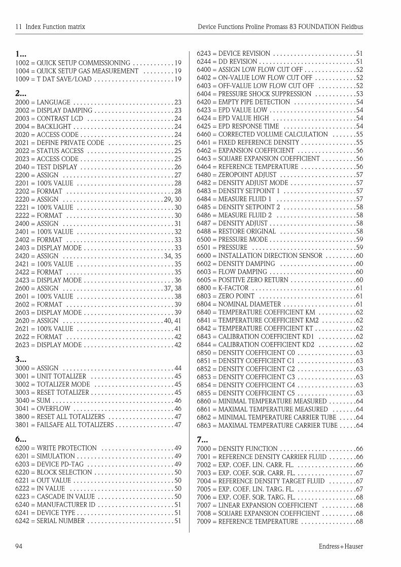
11 Index Function matrix Device Functions Proline Promass 83 FOUNDATION Fieldbus
94 Endress+Hauser
1...1002 = QUICK SETUP COMMISSIONING . . . . . . . . . . . . 19
1004 = QUICK SETUP GAS MEASUREMENT . . . . . . . . . 19
1009 = T DAT SAVE/LOAD . . . . . . . . . . . . . . . . . . . . . . . 19
2...2000 = LANGUAGE . . . . . . . . . . . . . . . . . . . . . . . . . . . . . 23
2002 = DISPLAY DAMPING . . . . . . . . . . . . . . . . . . . . . . . 23
2003 = CONTRAST LCD . . . . . . . . . . . . . . . . . . . . . . . . . 24
2004 = BACKLIGHT . . . . . . . . . . . . . . . . . . . . . . . . . . . . . 24
2020 = ACCESS CODE . . . . . . . . . . . . . . . . . . . . . . . . . . . 24
2021 = DEFINE PRIVATE CODE . . . . . . . . . . . . . . . . . . . 25
2022 = STATUS ACCESS . . . . . . . . . . . . . . . . . . . . . . . . . 25
2023 = ACCESS CODE . . . . . . . . . . . . . . . . . . . . . . . . . . . 25
2040 = TEST DISPLAY . . . . . . . . . . . . . . . . . . . . . . . . . . . 26
2200 = ASSIGN . . . . . . . . . . . . . . . . . . . . . . . . . . . . . . . . 27
2201 = 100% VALUE . . . . . . . . . . . . . . . . . . . . . . . . . . . . 28
2202 = FORMAT . . . . . . . . . . . . . . . . . . . . . . . . . . . . . . . 28
2220 = ASSIGN . . . . . . . . . . . . . . . . . . . . . . . . . . . . . 29, 30
2221 = 100% VALUE . . . . . . . . . . . . . . . . . . . . . . . . . . . . 30
2222 = FORMAT . . . . . . . . . . . . . . . . . . . . . . . . . . . . . . . 30
2400 = ASSIGN . . . . . . . . . . . . . . . . . . . . . . . . . . . . . . . . 31
2401 = 100% VALUE . . . . . . . . . . . . . . . . . . . . . . . . . . . . 32
2402 = FORMAT . . . . . . . . . . . . . . . . . . . . . . . . . . . . . . . 33
2403 = DISPLAY MODE . . . . . . . . . . . . . . . . . . . . . . . . . . 33
2420 = ASSIGN . . . . . . . . . . . . . . . . . . . . . . . . . . . . . 34, 35
2421 = 100% VALUE . . . . . . . . . . . . . . . . . . . . . . . . . . . . 35
2422 = FORMAT . . . . . . . . . . . . . . . . . . . . . . . . . . . . . . . 35
2423 = DISPLAY MODE . . . . . . . . . . . . . . . . . . . . . . . . . . 36
2600 = ASSIGN . . . . . . . . . . . . . . . . . . . . . . . . . . . . . 37, 38
2601 = 100% VALUE . . . . . . . . . . . . . . . . . . . . . . . . . . . . 38
2602 = FORMAT . . . . . . . . . . . . . . . . . . . . . . . . . . . . . . . 39
2603 = DISPLAY MODE . . . . . . . . . . . . . . . . . . . . . . . . . . 39
2620 = ASSIGN . . . . . . . . . . . . . . . . . . . . . . . . . . . . . 40, 41
2621 = 100% VALUE . . . . . . . . . . . . . . . . . . . . . . . . . . . . 41
2622 = FORMAT . . . . . . . . . . . . . . . . . . . . . . . . . . . . . . . 42
2623 = DISPLAY MODE . . . . . . . . . . . . . . . . . . . . . . . . . . 42
3...3000 = ASSIGN . . . . . . . . . . . . . . . . . . . . . . . . . . . . . . . . 44
3001 = UNIT TOTALIZER . . . . . . . . . . . . . . . . . . . . . . . . 45
3002 = TOTALIZER MODE . . . . . . . . . . . . . . . . . . . . . . . 45
3003 = RESET TOTALIZER . . . . . . . . . . . . . . . . . . . . . . . . 45
3040 = SUM . . . . . . . . . . . . . . . . . . . . . . . . . . . . . . . . . . . 46
3041 = OVERFLOW . . . . . . . . . . . . . . . . . . . . . . . . . . . . . 46
3800 = RESET ALL TOTALIZERS . . . . . . . . . . . . . . . . . . . 47
3801 = FAILSAFE ALL TOTALIZERS . . . . . . . . . . . . . . . . . 47
6...6200 = WRITE PROTECTION . . . . . . . . . . . . . . . . . . . . . 49
6201 = SIMULATION . . . . . . . . . . . . . . . . . . . . . . . . . . . . 49
6203 = DEVICE PD-TAG . . . . . . . . . . . . . . . . . . . . . . . . . 49
6220 = BLOCK SELECTION . . . . . . . . . . . . . . . . . . . . . . . 50
6221 = OUT VALUE . . . . . . . . . . . . . . . . . . . . . . . . . . . . . 50
6222 = IN VALUE . . . . . . . . . . . . . . . . . . . . . . . . . . . . . . 50
6223 = CASCADE IN VALUE . . . . . . . . . . . . . . . . . . . . . . 50
6240 = MANUFACTURER ID . . . . . . . . . . . . . . . . . . . . . . 51
6241 = DEVICE TYPE . . . . . . . . . . . . . . . . . . . . . . . . . . . . 51
6242 = SERIAL NUMBER . . . . . . . . . . . . . . . . . . . . . . . . . 51
6243 = DEVICE REVISION . . . . . . . . . . . . . . . . . . . . . . . .51
6244 = DD REVISION . . . . . . . . . . . . . . . . . . . . . . . . . . . .51
6400 = ASSIGN LOW FLOW CUT OFF . . . . . . . . . . . . . . .52
6402 = ON-VALUE LOW FLOW CUT OFF . . . . . . . . . . . .52
6403 = OFF-VALUE LOW FLOW CUT OFF . . . . . . . . . . .52
6404 = PRESSURE SHOCK SUPPRESSION . . . . . . . . . . . .53
6420 = EMPTY PIPE DETECTION . . . . . . . . . . . . . . . . . .54
6423 = EPD VALUE LOW . . . . . . . . . . . . . . . . . . . . . . . . .54
6424 = EPD VALUE HIGH . . . . . . . . . . . . . . . . . . . . . . . .54
6425 = EPD RESPONSE TIME . . . . . . . . . . . . . . . . . . . . .54
6460 = CORRECTED VOLUME CALCULATION . . . . . . .55
6461 = FIXED REFERENCE DENSITY . . . . . . . . . . . . . . . .55
6462 = EXPANSION COEFFICIENT . . . . . . . . . . . . . . . . .56
6463 = SQUARE EXPANSION COEFFICIENT . . . . . . . . . .56
6464 = REFERENCE TEMPERATURE . . . . . . . . . . . . . . . .56
6480 = ZEROPOINT ADJUST . . . . . . . . . . . . . . . . . . . . . .57
6482 = DENSITY ADJUST MODE . . . . . . . . . . . . . . . . . . .57
6483 = DENSITY SETPOINT 1 . . . . . . . . . . . . . . . . . . . . .57
6484 = MEASURE FLUID 1 . . . . . . . . . . . . . . . . . . . . . . .57
6485 = DENSITY SETPOINT 2 . . . . . . . . . . . . . . . . . . . . .58
6486 = MEASURE FLUID 2 . . . . . . . . . . . . . . . . . . . . . . .58
6487 = DENSITY ADJUST . . . . . . . . . . . . . . . . . . . . . . . . .58
6488 = RESTORE ORIGINAL . . . . . . . . . . . . . . . . . . . . . .58
6500 = PRESSURE MODE . . . . . . . . . . . . . . . . . . . . . . . . .59
6501 = PRESSURE . . . . . . . . . . . . . . . . . . . . . . . . . . . . . .59
6600 = INSTALLATION DIRECTION SENSOR . . . . . . . . .60
6602 = DENSITY DAMPING . . . . . . . . . . . . . . . . . . . . . .60
6603 = FLOW DAMPING . . . . . . . . . . . . . . . . . . . . . . . . .60
6605 = POSITIVE ZERO RETURN . . . . . . . . . . . . . . . . . . .60
6800 = K-FACTOR . . . . . . . . . . . . . . . . . . . . . . . . . . . . . .61
6803 = ZERO POINT . . . . . . . . . . . . . . . . . . . . . . . . . . . .61
6804 = NOMINAL DIAMETER . . . . . . . . . . . . . . . . . . . . .61
6840 = TEMPERATURE COEFFICIENT KM . . . . . . . . . . .62
6841 = TEMPERATURE COEFFICIENT KM2 . . . . . . . . . .62
6842 = TEMPERATURE COEFFICIENT KT . . . . . . . . . . . .62
6843 = CALIBRATION COEFFICIENT KD1 . . . . . . . . . . .62
6844 = CALIBRATION COEFFICIENT KD2 . . . . . . . . . . .62
6850 = DENSITY COEFFICIENT C0 . . . . . . . . . . . . . . . . .63
6851 = DENSITY COEFFICIENT C1 . . . . . . . . . . . . . . . . .63
6852 = DENSITY COEFFICIENT C2 . . . . . . . . . . . . . . . . .63
6853 = DENSITY COEFFICIENT C3 . . . . . . . . . . . . . . . . .63
6854 = DENSITY COEFFICIENT C4 . . . . . . . . . . . . . . . . .63
6855 = DENSITY COEFFICIENT C5 . . . . . . . . . . . . . . . . .63
6860 = MINIMAL TEMPERATURE MEASURED . . . . . . . .64
6861 = MAXIMAL TEMPERATURE MEASURED . . . . . . .64
6862 = MINIMAL TEMPERATURE CARRIER TUBE . . . . .64
6863 = MAXIMAL TEMPERATURE CARRIER TUBE . . . . .64
7...7000 = DENSITY FUNCTION . . . . . . . . . . . . . . . . . . . . . .66
7001 = REFERENCE DENSITY CARRIER FLUID . . . . . . . .66
7002 = EXP. COEF. LIN. CARR. FL. . . . . . . . . . . . . . . . . .66
7003 = EXP. COEF. SQR. CARR. FL. . . . . . . . . . . . . . . . . .67
7004 = REFERENCE DENSITY TARGET FLUID . . . . . . . .67
7005 = EXP. COEF. LIN. TARG. FL. . . . . . . . . . . . . . . . . .67
7006 = EXP. COEF. SQR. TARG. FL. . . . . . . . . . . . . . . . . .68
7007 = LINEAR EXPANSION COEFFICIENT . . . . . . . . . .68
7008 = SQUARE EXPANSION COEFFICIENT . . . . . . . . . .68
7009 = REFERENCE TEMPERATURE . . . . . . . . . . . . . . . .68

Device Functions Proline Promass 83 FOUNDATION Fieldbus 11 Index Function matrix
Endress+Hauser 95
7021 = MODE . . . . . . . . . . . . . . . . . . . . . . . . . . . . . . . . . 69
7022 = CONCENTRATION SELECTOR . . . . . . . . . . . . . . 70
7031 = CONCENTRATION NAME . . . . . . . . . . . . . . . . . 70
7032 = COEFFICIENT A0 . . . . . . . . . . . . . . . . . . . . . . . . 70
7033 = COEFFICIENT A1 . . . . . . . . . . . . . . . . . . . . . . . . 70
7034 = COEFFICIENT A2 . . . . . . . . . . . . . . . . . . . . . . . . 70
7035 = COEFFICIENT A3 . . . . . . . . . . . . . . . . . . . . . . . . 70
7036 = COEFFICIENT A4 . . . . . . . . . . . . . . . . . . . . . . . . 71
7037 = COEFFICIENT B1 . . . . . . . . . . . . . . . . . . . . . . . . 71
7038 = COEFFICIENT B2 . . . . . . . . . . . . . . . . . . . . . . . . 71
7039 = COEFFICIENT B3 . . . . . . . . . . . . . . . . . . . . . . . . 71
7401 = REFERENCE CONDITION USER . . . . . . . . . . . . . 72
7402 = SELECT REFERENCE CONDITION . . . . . . . . . . . 72
7403 = WARNING MODE . . . . . . . . . . . . . . . . . . . . . . . 72
7410 = ACQUISITION MODE . . . . . . . . . . . . . . . . . . . . . 73
7411 = ACQUISITION PERIOD . . . . . . . . . . . . . . . . . . . . 73
7412 = ACQUISITION DO . . . . . . . . . . . . . . . . . . . . . . . 73
7413 = RESET HISTORY . . . . . . . . . . . . . . . . . . . . . . . . . 73
7420 = REFERENCE VALUE MASS FLOW . . . . . . . . . . . 74
7421 = MASS FLOW . . . . . . . . . . . . . . . . . . . . . . . . . . . . 74
7422 = MINIMUM MASS FLOW . . . . . . . . . . . . . . . . . . . 74
7423 = MAXIMUM MASS FLOW . . . . . . . . . . . . . . . . . . 74
7424 = HISTORY MASS FLOW . . . . . . . . . . . . . . . . . . . . 74
7425 = DEVIATION MASS FLOW . . . . . . . . . . . . . . . . . . 74
7426 = WARNING LEVEL . . . . . . . . . . . . . . . . . . . . . . . . 74
7430 = REFERENCE VALUE DENSITY . . . . . . . . . . . . . . 75
7431 = DENSITY . . . . . . . . . . . . . . . . . . . . . . . . . . . . . . . 75
7432 = MINIMUM DENSITY . . . . . . . . . . . . . . . . . . . . . 75
7433 = MAXIMUM DENSITY . . . . . . . . . . . . . . . . . . . . . 75
7434 = HISTORY DENSITY . . . . . . . . . . . . . . . . . . . . . . . 75
7435 = DEVIATION DENSITY . . . . . . . . . . . . . . . . . . . . . 75
7436 = WARNING LEVEL . . . . . . . . . . . . . . . . . . . . . . . . 75
7440 = REFERENCE VALUE REFERENCE DENSITY . . . . 76
7441 = REFERENCE DENSITY . . . . . . . . . . . . . . . . . . . . 76
7442 = MINIMUM REFERENCE DENSITY . . . . . . . . . . . 76
7443 = MAXIMUM REFERENCE DENSITY . . . . . . . . . . . 76
7444 = HISTORY REFERENCE DENSITY . . . . . . . . . . . . . 76
7445 = DEVIATION REFERENCE DENSITY . . . . . . . . . . 76
7446 = WARNING LEVEL . . . . . . . . . . . . . . . . . . . . . . . . 76
7450 = REFERENCE VALUE TEMPERATURE . . . . . . . . . 77
7451 = TEMPERATURE . . . . . . . . . . . . . . . . . . . . . . . . . 77
7452 = MINIMUM TEMPERATURE . . . . . . . . . . . . . . . . 77
7453 = MAXIMUM TEMPERATURE . . . . . . . . . . . . . . . . 77
7454 = HISTORY TEMPERATURE . . . . . . . . . . . . . . . . . . 77
7455 = DEVIATION TEMPERATURE . . . . . . . . . . . . . . . 77
7456 = WARNING LEVEL . . . . . . . . . . . . . . . . . . . . . . . . 77
7460 = REFERENCE VALUE TUBE DAMPING . . . . . . . . 78
7461 = TUBE DAMPING . . . . . . . . . . . . . . . . . . . . . . . . . 78
7462 = MINIMUM TUBE DAMPING . . . . . . . . . . . . . . . 78
7463 = MAXIMUM TUBE DAMPING . . . . . . . . . . . . . . . 78
7464 = HISTORY TUBE DAMPING . . . . . . . . . . . . . . . . . 78
7465 = DEVIATION TUBE DAMPING . . . . . . . . . . . . . . . 78
7466 = WARNING LEVEL . . . . . . . . . . . . . . . . . . . . . . . . 78
7470 = REF. VALUE EL.-DYN. SENSORS . . . . . . . . . . . . . 79
7471 = ELECTRODYNAMIC SENSORS . . . . . . . . . . . . . . 79
7472 = MINIMUM EL-DYN. SENSORS . . . . . . . . . . . . . . 79
7473 = MAXIMUM EL-DYN. SENSORS . . . . . . . . . . . . . . 79
7474 = HISTORY EL-DYN. SENSORS . . . . . . . . . . . . . . . 79
7475 = DEVIATION EL-DYN. SENSORS . . . . . . . . . . . . . 79
7476 = WARNING LEVEL . . . . . . . . . . . . . . . . . . . . . . . . 80
7480 = REF. VALUE OP. FREQ. FLUCT. . . . . . . . . . . . . . 80
7481 = OPERATING FREQUENCY FLUCT. . . . . . . . . . . . 80
7482 = MINIMUM OPERATING FREQUENCY FLUCT. . . 80
7483 = MAXIMUM OPERATING FREQUENCY FLUCT. . 80
7484 = HISTORY OPERATING FREQUENCY FLUCT. . . . 81
7485 = DEVIATION OPERATING FREQUENCY FLUCT. . 81
7486 = WARNING LEVEL . . . . . . . . . . . . . . . . . . . . . . . . 81
7490 = REF. VALUE TUBE DAMPING FLUCT. . . . . . . . . 81
7491 = TUBE DAMPING FLUCTUATION . . . . . . . . . . . . 82
7492 = MINIMUM TUBE DAMPING FLUCT. . . . . . . . . . 82
7493 = MAXIMUM TUBE DAMPING FLUCT. . . . . . . . . . 82
7494 = HISTORY TUBE DAMPING FLUCT. . . . . . . . . . . 82
7495 = DEVIATION TUBE DAMPING FLUCT. . . . . . . . . 82
7496 = WARNING LEVEL . . . . . . . . . . . . . . . . . . . . . . . . 82
8...8005 = ALARM DELAY . . . . . . . . . . . . . . . . . . . . . . . . . . 84
8006 = REMOVE SW-OPTION . . . . . . . . . . . . . . . . . . . . 84
8007 = PERMANENT STORAGE . . . . . . . . . . . . . . . . . . . 84
8040 = ACTUAL SYSTEM CONDITION . . . . . . . . . . . . . 85
8041 = PREVIOUS SYSTEM CONDITION . . . . . . . . . . . . 85
8042 = SIMULATION FAILSAFE MODE . . . . . . . . . . . . . 85
8043 = SIMULATION MEASURAND . . . . . . . . . . . . . . . . 85
8044 = VALUE SIMULATION MEASURAND . . . . . . . . . . 86
8046 = SYSTEM RESET . . . . . . . . . . . . . . . . . . . . . . . . . . 86
8048 = OPERATION HOURS . . . . . . . . . . . . . . . . . . . . . . 86
8200 = SERIAL NUMBER . . . . . . . . . . . . . . . . . . . . . . . . 87
8201 = SENSOR TYPE . . . . . . . . . . . . . . . . . . . . . . . . . . . 87
8205 = SW REV. NO. S-DAT . . . . . . . . . . . . . . . . . . . . . . 87
8222 = SW REV. NO. AMPLIFIER . . . . . . . . . . . . . . . . . . 88
8225 = SOFTWARE REV. NO. T-DAT . . . . . . . . . . . . . . . 88
8226 = LANGUAGE GROUP . . . . . . . . . . . . . . . . . . . . . . 88
8240 = STATUS F-CHIP . . . . . . . . . . . . . . . . . . . . . . . . . . 88
8241 = SYSTEM OPTION . . . . . . . . . . . . . . . . . . . . . . . . 89
8244 = SW REV. NO. F-CHIP . . . . . . . . . . . . . . . . . . . . . 89
8300 = I/O MODULE TYPE . . . . . . . . . . . . . . . . . . . . . . 89
8303 = SW REV. NUMBER I/O MODULE . . . . . . . . . . . . 89

11 Index Function matrix Device Functions Proline Promass 83 FOUNDATION Fieldbus
96 Endress+Hauser

Device Functions Proline Promass 83 FOUNDATION Fieldbus 12 Index local operation
Endress+Hauser 97
12 Index local operation
AAccess code . . . . . . . . . . . . . . . . . . . . . . . . . . . . . . . . . . . 24
Acquisition
Do . . . . . . . . . . . . . . . . . . . . . . . . . . . . . . . . . . . . . . . 73
Mode . . . . . . . . . . . . . . . . . . . . . . . . . . . . . . . . . . . . . 73
Period . . . . . . . . . . . . . . . . . . . . . . . . . . . . . . . . . . . . . 73
Acquisition (Advanced diagnostics) . . . . . . . . . . . . . . . . . . 73
Actual system condition . . . . . . . . . . . . . . . . . . . . . . . . . . 85
Additional coefficient . . . . . . . . . . . . . . . . . . . . . . . . . . . . 64
Additional configuration . . . . . . . . . . . . . . . . . . . . . . . . . . 17
Additional line
Configuration . . . . . . . . . . . . . . . . . . . . . . . . . . . . . . . 31
Multiplex . . . . . . . . . . . . . . . . . . . . . . . . . . . . . . . . . . 34
Adjustment
Density . . . . . . . . . . . . . . . . . . . . . . . . . . . . . . . . . . . . 58
Zero point . . . . . . . . . . . . . . . . . . . . . . . . . . . . . . . . . . 57
Advanced diagnostics
Acquisition . . . . . . . . . . . . . . . . . . . . . . . . . . . . . . . . . 73
Configuration . . . . . . . . . . . . . . . . . . . . . . . . . . . . . . . 72
Density . . . . . . . . . . . . . . . . . . . . . . . . . . . . . . . . . . . . 75
Electrodyn. sensors . . . . . . . . . . . . . . . . . . . . . . . . . . . 79
Mass flow . . . . . . . . . . . . . . . . . . . . . . . . . . . . . . . . . . 74
Operating frequency fluctuation . . . . . . . . . . . . . . . . . 80
Reference density . . . . . . . . . . . . . . . . . . . . . . . . . . . . 76
Temperature . . . . . . . . . . . . . . . . . . . . . . . . . . . . . . . . 77
Tube damping . . . . . . . . . . . . . . . . . . . . . . . . . . . . . . 78
Tube damping fluctuation . . . . . . . . . . . . . . . . . . . . . . 81
Alarm delay . . . . . . . . . . . . . . . . . . . . . . . . . . . . . . . . . . . 84
Amplifier (Version-info) . . . . . . . . . . . . . . . . . . . . . . . . . . 88
Assign
Additional line . . . . . . . . . . . . . . . . . . . . . . . . . . . 31, 32
Additional line (Multiplex) . . . . . . . . . . . . . . . . . . 34, 35
Information line . . . . . . . . . . . . . . . . . . . . . . . . . . 37, 38
Information line (Multiplex) . . . . . . . . . . . . . . . . . 40, 41
Low flow cut off . . . . . . . . . . . . . . . . . . . . . . . . . . . . . 52
Main line . . . . . . . . . . . . . . . . . . . . . . . . . . . . . . . . . . 27
Main line (Multiplex) . . . . . . . . . . . . . . . . . . . . . . 29, 30
Totalizer . . . . . . . . . . . . . . . . . . . . . . . . . . . . . . . . . . . 44
BBacklight (display) . . . . . . . . . . . . . . . . . . . . . . . . . . . . . . 24
Basic configuration (User interface) . . . . . . . . . . . . . . . . . . 23
Basic functions
FOUNDATION Fieldbus
Configuration . . . . . . . . . . . . . . . . . . . . . . . . . . . 49
Function blocks . . . . . . . . . . . . . . . . . . . . . . . . . 50
Information . . . . . . . . . . . . . . . . . . . . . . . . . . . . 51
Process parameter
Adjustment . . . . . . . . . . . . . . . . . . . . . . . . . . . . 57
Configuration . . . . . . . . . . . . . . . . . . . . . . . . . . . 52
EPD parameter . . . . . . . . . . . . . . . . . . . . . . . . . . 54
Reference parameter . . . . . . . . . . . . . . . . . . . . . . 55
Sensor data
Additional coefficient . . . . . . . . . . . . . . . . . . . . . 64
Configuration . . . . . . . . . . . . . . . . . . . . . . . . . . . 61
Density coefficient . . . . . . . . . . . . . . . . . . . . . . . 63
Flow coefficient . . . . . . . . . . . . . . . . . . . . . . . . . 62
System parameter
Configuration . . . . . . . . . . . . . . . . . . . . . . . . . . . 60
Block
Basic functions . . . . . . . . . . . . . . . . . . . . . . . . . . . . . . 48
Measured variables . . . . . . . . . . . . . . . . . . . . . . . . . . . . 9
Quick Setup . . . . . . . . . . . . . . . . . . . . . . . . . . . . . . . . 19
Special function . . . . . . . . . . . . . . . . . . . . . . . . . . . . . . 65
Supervision . . . . . . . . . . . . . . . . . . . . . . . . . . . . . . . . . 83
Totalizer . . . . . . . . . . . . . . . . . . . . . . . . . . . . . . . . . . . 43
Block Selection . . . . . . . . . . . . . . . . . . . . . . . . . . . . . . . . . 50
CCalibration
Coefficient
KD1 . . . . . . . . . . . . . . . . . . . . . . . . . . . . . . . . . . 62
KD2 . . . . . . . . . . . . . . . . . . . . . . . . . . . . . . . . . . 62
Carrier mass flow . . . . . . . . . . . . . . . . . . . . . . . . . . . . . . . 12
Carrier volume flow . . . . . . . . . . . . . . . . . . . . . . . . . . . . . 12
Cascade IN Value . . . . . . . . . . . . . . . . . . . . . . . . . . . . . . . 50
Coefficient
Calibration
KD1 . . . . . . . . . . . . . . . . . . . . . . . . . . . . . . . . . . 62
KD2 . . . . . . . . . . . . . . . . . . . . . . . . . . . . . . . . . . 62
Concentration
A0 . . . . . . . . . . . . . . . . . . . . . . . . . . . . . . . . . . . 70
A1 . . . . . . . . . . . . . . . . . . . . . . . . . . . . . . . . . . . 70
A2 . . . . . . . . . . . . . . . . . . . . . . . . . . . . . . . . . . . 70
A3 . . . . . . . . . . . . . . . . . . . . . . . . . . . . . . . . . . . 70
A4 . . . . . . . . . . . . . . . . . . . . . . . . . . . . . . . . . . . 71
B1 . . . . . . . . . . . . . . . . . . . . . . . . . . . . . . . . . . . 71
B2 . . . . . . . . . . . . . . . . . . . . . . . . . . . . . . . . . . . 71
B3 . . . . . . . . . . . . . . . . . . . . . . . . . . . . . . . . . . . 71
Density
C0 . . . . . . . . . . . . . . . . . . . . . . . . . . . . . . . . . . . 63
C1 . . . . . . . . . . . . . . . . . . . . . . . . . . . . . . . . . . . 63
C2 . . . . . . . . . . . . . . . . . . . . . . . . . . . . . . . . . . . 63
C3 . . . . . . . . . . . . . . . . . . . . . . . . . . . . . . . . . . . 63
C4 . . . . . . . . . . . . . . . . . . . . . . . . . . . . . . . . . . . 63
C5 . . . . . . . . . . . . . . . . . . . . . . . . . . . . . . . . . . . 63
Expansion . . . . . . . . . . . . . . . . . . . . . . . . . . . . . . . . . . 56
Quadratic expansion . . . . . . . . . . . . . . . . . . . . . . . . . . 56
Temperature
KM . . . . . . . . . . . . . . . . . . . . . . . . . . . . . . . . . . . 62
KM2 . . . . . . . . . . . . . . . . . . . . . . . . . . . . . . . . . . 62
KT . . . . . . . . . . . . . . . . . . . . . . . . . . . . . . . . . . . 62
Commissioning . . . . . . . . . . . . . . . . . . . . . . . . . . . . . . . . . 19
Concentration selection (density function) . . . . . . . . . . . . . 70
Configuration
Additional line . . . . . . . . . . . . . . . . . . . . . . . . . . . . . . 31
Advanced diagnostics . . . . . . . . . . . . . . . . . . . . . . . . . 72
Density functions . . . . . . . . . . . . . . . . . . . . . . . . . . . . 66
FOUNDATION Fieldbus . . . . . . . . . . . . . . . . . . . . . . . 49
Information line . . . . . . . . . . . . . . . . . . . . . . . . . . . . . 37
Main line . . . . . . . . . . . . . . . . . . . . . . . . . . . . . . . . . . 27
Process parameter . . . . . . . . . . . . . . . . . . . . . . . . . . . . 52

12 Index local operation Device Functions Proline Promass 83 FOUNDATION Fieldbus
98 Endress+Hauser
Sensor data . . . . . . . . . . . . . . . . . . . . . . . . . . . . . . . . . 61
System . . . . . . . . . . . . . . . . . . . . . . . . . . . . . . . . . . . . . 84
System parameter . . . . . . . . . . . . . . . . . . . . . . . . . . . . 60
System units . . . . . . . . . . . . . . . . . . . . . . . . . . . . . . . . 14
Totalizer . . . . . . . . . . . . . . . . . . . . . . . . . . . . . . . . . . . 44
Contrast LCD . . . . . . . . . . . . . . . . . . . . . . . . . . . . . . . . . . 24
Control (User interface)
Basic configuration . . . . . . . . . . . . . . . . . . . . . . . . . . . . 23
Operation . . . . . . . . . . . . . . . . . . . . . . . . . . . . . . . . . . 26
Unlocking/locking . . . . . . . . . . . . . . . . . . . . . . . . . . . . 24
Corrected Carrier volume flow . . . . . . . . . . . . . . . . . . . . . 13
Corrected target volume flow . . . . . . . . . . . . . . . . . . . . . . 12
Corrected volume calculation . . . . . . . . . . . . . . . . . . . . . . 55
Corrected volume flow . . . . . . . . . . . . . . . . . . . . . . . . . . . 10
DDamping
Density . . . . . . . . . . . . . . . . . . . . . . . . . . . . . . . . . . . . 60
Display . . . . . . . . . . . . . . . . . . . . . . . . . . . . . . . . . . . . 23
Flow . . . . . . . . . . . . . . . . . . . . . . . . . . . . . . . . . . . . . . 60
DD Revision . . . . . . . . . . . . . . . . . . . . . . . . . . . . . . . . . . . 51
Define private code . . . . . . . . . . . . . . . . . . . . . . . . . . . . . . 25
Density . . . . . . . . . . . . . . . . . . . . . . . . . . . . . . . . . . . . . . . 10
Adjustment . . . . . . . . . . . . . . . . . . . . . . . . . . . . . . . . . 58
Coefficient C0 . . . . . . . . . . . . . . . . . . . . . . . . . . . . . . . 63
Coefficient C1 . . . . . . . . . . . . . . . . . . . . . . . . . . . . . . . 63
Coefficient C2 . . . . . . . . . . . . . . . . . . . . . . . . . . . . . . . 63
Coefficient C3 . . . . . . . . . . . . . . . . . . . . . . . . . . . . . . . 63
Coefficient C4 . . . . . . . . . . . . . . . . . . . . . . . . . . . . . . . 63
Coefficient C5 . . . . . . . . . . . . . . . . . . . . . . . . . . . . . . . 63
Damping . . . . . . . . . . . . . . . . . . . . . . . . . . . . . . . . . . . 60
Fixed reference density . . . . . . . . . . . . . . . . . . . . . . . . 55
Function . . . . . . . . . . . . . . . . . . . . . . . . . . . . . . . . . . . 66
Density Adjust mode . . . . . . . . . . . . . . . . . . . . . . . . . . . . . 57
Density functions
Configuration . . . . . . . . . . . . . . . . . . . . . . . . . . . . . . . . 66
Density (Advanced diagnostics)
Density . . . . . . . . . . . . . . . . . . . . . . . . . . . . . . . . . . . . 75
Deviation . . . . . . . . . . . . . . . . . . . . . . . . . . . . . . . . . . . 75
History . . . . . . . . . . . . . . . . . . . . . . . . . . . . . . . . . . . . 75
Maximum . . . . . . . . . . . . . . . . . . . . . . . . . . . . . . . . . . 75
Minimum . . . . . . . . . . . . . . . . . . . . . . . . . . . . . . . . . . 75
Warning level . . . . . . . . . . . . . . . . . . . . . . . . . . . . . . . 75
Device PD-Tag . . . . . . . . . . . . . . . . . . . . . . . . . . . . . . . . . 49
Device revision . . . . . . . . . . . . . . . . . . . . . . . . . . . . . . . . . 51
Device type . . . . . . . . . . . . . . . . . . . . . . . . . . . . . . . . . . . . 51
Device (version-info) . . . . . . . . . . . . . . . . . . . . . . . . . . . . . 87
Display
Additional line . . . . . . . . . . . . . . . . . . . . . . . . . . . . . . . 31
Main line . . . . . . . . . . . . . . . . . . . . . . . . . . . . . . . . . . . 27
Test . . . . . . . . . . . . . . . . . . . . . . . . . . . . . . . . . . . . . . . 26
Display light . . . . . . . . . . . . . . . . . . . . . . . . . . . . . . . . . . . 24
Display mode
Additional line . . . . . . . . . . . . . . . . . . . . . . . . . . . . . . . 33
Additional line (Multiplex) . . . . . . . . . . . . . . . . . . . . . . 36
Information line . . . . . . . . . . . . . . . . . . . . . . . . . . . . . . 39
Information line (Multiplex) . . . . . . . . . . . . . . . . . . . . . 42
EElectrodyn. sensors (Advanced diagnostics)
Deviation . . . . . . . . . . . . . . . . . . . . . . . . . . . . . . . . . . .79
Electrodyn. sensors . . . . . . . . . . . . . . . . . . . . . . . . . . . .79
History . . . . . . . . . . . . . . . . . . . . . . . . . . . . . . . . . . . . .79
Maximum . . . . . . . . . . . . . . . . . . . . . . . . . . . . . . . . . .79
Minimum . . . . . . . . . . . . . . . . . . . . . . . . . . . . . . . .79, 80
Warning . . . . . . . . . . . . . . . . . . . . . . . . . . . . . . . . . . . .80
Empty pipe detection
EPD . . . . . . . . . . . . . . . . . . . . . . . . . . . . . . . . . . . . . . .54
Response time . . . . . . . . . . . . . . . . . . . . . . . . . . . . . . .54
Value high . . . . . . . . . . . . . . . . . . . . . . . . . . . . . . . . . .54
Value low . . . . . . . . . . . . . . . . . . . . . . . . . . . . . . . . . . .54
EPD
Response time . . . . . . . . . . . . . . . . . . . . . . . . . . . . . . .55
Expansion
Coefficient . . . . . . . . . . . . . . . . . . . . . . . . . . . . . . . . . .56
Coefficient squarely . . . . . . . . . . . . . . . . . . . . . . . . . . .56
Expansion coefficient
Linear . . . . . . . . . . . . . . . . . . . . . . . . . . . . . . . . . . . . .68
Carrier fluid . . . . . . . . . . . . . . . . . . . . . . . . . . . . .66
Target fluid . . . . . . . . . . . . . . . . . . . . . . . . . . . . .67
Square . . . . . . . . . . . . . . . . . . . . . . . . . . . . . . . . . . . . .68
Carrier fluid . . . . . . . . . . . . . . . . . . . . . . . . . . . . .67
Target fluid . . . . . . . . . . . . . . . . . . . . . . . . . . . . .68
FFactory settings
Full scale value . . . . . . . . . . . . . . . . . . . . . . .90, 193, 195
Low flow cut off . . . . . . . . . . . . . . . . . . . . . .90, 193, 195
Pulse value . . . . . . . . . . . . . . . . . . . . . . . . . .90, 193, 195
Failsafe
All totalizers . . . . . . . . . . . . . . . . . . . . . . . . . . . . . . . . .47
F-CHIP (Version Info) . . . . . . . . . . . . . . . . . . . . . . . . . . . .88
Fixed reference density . . . . . . . . . . . . . . . . . . . . . . . . . . .55
Flow
Coefficient . . . . . . . . . . . . . . . . . . . . . . . . . . . . . . . . . .62
Damping . . . . . . . . . . . . . . . . . . . . . . . . . . . . . . . . . . .60
Format
Additional line . . . . . . . . . . . . . . . . . . . . . . . . . . . . . . .33
Additional line (Multiplex) . . . . . . . . . . . . . . . . . . . . . .35
Information line . . . . . . . . . . . . . . . . . . . . . . . . . . . . . .39
Information line (Multiplex) . . . . . . . . . . . . . . . . . . . . .42
Main line . . . . . . . . . . . . . . . . . . . . . . . . . . . . . . . . . . .28
Main line (Multiplex) . . . . . . . . . . . . . . . . . . . . . . . . . .30
FOUNDATION Fieldbus
Configuration . . . . . . . . . . . . . . . . . . . . . . . . . . . . . . . .49
Function blocks . . . . . . . . . . . . . . . . . . . . . . . . . . . . . .50
Information . . . . . . . . . . . . . . . . . . . . . . . . . . . . . . . . .51
Function group
Acquisition
Advanced diagnostics . . . . . . . . . . . . . . . . . . . . . .73
Amplifier . . . . . . . . . . . . . . . . . . . . . . . . . . . . . . . . . . .88
Configuration
Advanced diagnostics . . . . . . . . . . . . . . . . . . . . . .72
Density functions . . . . . . . . . . . . . . . . . . . . . . . . .66
System . . . . . . . . . . . . . . . . . . . . . . . . . . . . . . . . .84

Device Functions Proline Promass 83 FOUNDATION Fieldbus 12 Index local operation
Endress+Hauser 99
Density
Advanced diagnostics . . . . . . . . . . . . . . . . . . . . . 75
Device . . . . . . . . . . . . . . . . . . . . . . . . . . . . . . . . . . . . 87
Electrodyn. sensors
Advanced diagnostics . . . . . . . . . . . . . . . . . . . . . 79
F-CHIP . . . . . . . . . . . . . . . . . . . . . . . . . . . . . . . . . . . . 88
Mass flow
Advanced diagnostics . . . . . . . . . . . . . . . . . . . . . 74
Operating frequency fluctuation
Advanced diagnostics . . . . . . . . . . . . . . . . . . . . . 80
Operation
System . . . . . . . . . . . . . . . . . . . . . . . . . . . . . . . . 85
Pressure correction . . . . . . . . . . . . . . . . . . . . . . . . . . . 59
Reference density
Advanced diagnostics . . . . . . . . . . . . . . . . . . . . . 76
Sensor . . . . . . . . . . . . . . . . . . . . . . . . . . . . . . . . . . . . 87
Temperature
Advanced diagnostics . . . . . . . . . . . . . . . . . . . . . 77
Tube damping
Advanced diagnostics . . . . . . . . . . . . . . . . . . . . . 78
Tube damping fluctuation
Advanced diagnostics . . . . . . . . . . . . . . . . . . . . . 81
Function groups
Additional coefficient . . . . . . . . . . . . . . . . . . . . . . . . . 64
Additional configuration (System units) . . . . . . . . . . . . 17
Adjustment (process parameter) . . . . . . . . . . . . . . . . . 57
Basic configuration (User interface) . . . . . . . . . . . . . . . 23
Configuration
Additional line . . . . . . . . . . . . . . . . . . . . . . . . . . 31
FOUNDATION Fieldbus . . . . . . . . . . . . . . . . . . . 49
Information line . . . . . . . . . . . . . . . . . . . . . . . . . 37
Main line . . . . . . . . . . . . . . . . . . . . . . . . . . . . . . 27
Process parameter . . . . . . . . . . . . . . . . . . . . . . . 52
Sensor data . . . . . . . . . . . . . . . . . . . . . . . . . . . . . 61
System parameter . . . . . . . . . . . . . . . . . . . . . . . . 60
System units . . . . . . . . . . . . . . . . . . . . . . . . . . . . 14
Totalizer . . . . . . . . . . . . . . . . . . . . . . . . . . . . . . . 44
Density coefficient . . . . . . . . . . . . . . . . . . . . . . . . . . . 63
EPD parameter . . . . . . . . . . . . . . . . . . . . . . . . . . . . . . 54
Flow coefficient . . . . . . . . . . . . . . . . . . . . . . . . . . . . . 62
Function blocks . . . . . . . . . . . . . . . . . . . . . . . . . . . . . 50
Information (FOUNDATION Fieldbus) . . . . . . . . . . . . 51
I/O Module . . . . . . . . . . . . . . . . . . . . . . . . . . . . . . . . 89
Main values . . . . . . . . . . . . . . . . . . . . . . . . . . . . . . . . 10
Multiplex
Additional line . . . . . . . . . . . . . . . . . . . . . . . . . . 34
Information line . . . . . . . . . . . . . . . . . . . . . . . . . 40
Main line . . . . . . . . . . . . . . . . . . . . . . . . . . . . . . 29
Operation
Totalizer . . . . . . . . . . . . . . . . . . . . . . . . . . . . . . . 46
User interface . . . . . . . . . . . . . . . . . . . . . . . . . . . 26
Reference parameter . . . . . . . . . . . . . . . . . . . . . . . . . . 55
Unlocking/locking (User interface) . . . . . . . . . . . . . . . 24
Function matrix
Codes identifying . . . . . . . . . . . . . . . . . . . . . . . . . . . . . 7
Layout . . . . . . . . . . . . . . . . . . . . . . . . . . . . . . . . . . . . . 6
Overview . . . . . . . . . . . . . . . . . . . . . . . . . . . . . . . . . . . 8
GGas measurement . . . . . . . . . . . . . . . . . . . . . . . . . . . . . . . 19
Group
Advanced diagnostics . . . . . . . . . . . . . . . . . . . . . . . . . 72
Batching function . . . . . . . . . . . . . . . . . . . . . . . . . . . . 72
System . . . . . . . . . . . . . . . . . . . . . . . . . . . . . . . . . . . . 84
Version-info . . . . . . . . . . . . . . . . . . . . . . . . . . . . . . . . 87
Groups
Additional line . . . . . . . . . . . . . . . . . . . . . . . . . . . . . . 31
Control (User interface) . . . . . . . . . . . . . . . . . . . . . . . . 23
FOUNDATION Fieldbus . . . . . . . . . . . . . . . . . . . . . . . 49
Handling Totalizer . . . . . . . . . . . . . . . . . . . . . . . . . . . . 47
Information line . . . . . . . . . . . . . . . . . . . . . . . . . . . . . 37
Main line . . . . . . . . . . . . . . . . . . . . . . . . . . . . . . . . . . 27
Measuring values . . . . . . . . . . . . . . . . . . . . . . . . . . . . 10
Process parameter . . . . . . . . . . . . . . . . . . . . . . . . . . . . 52
Sensor data . . . . . . . . . . . . . . . . . . . . . . . . . . . . . . . . . 61
System parameter . . . . . . . . . . . . . . . . . . . . . . . . . . . . 60
System units . . . . . . . . . . . . . . . . . . . . . . . . . . . . . . . . 11
Totalizer (1 to 3) . . . . . . . . . . . . . . . . . . . . . . . . . . . . . 44
HHandling Totalizer . . . . . . . . . . . . . . . . . . . . . . . . . . . . . . 47
IIN Value . . . . . . . . . . . . . . . . . . . . . . . . . . . . . . . . . . . . . . 50
Information line
Configuration . . . . . . . . . . . . . . . . . . . . . . . . . . . . . . . 37
Multiplex . . . . . . . . . . . . . . . . . . . . . . . . . . . . . . . . . . 40
Installation direction sensor . . . . . . . . . . . . . . . . . . . . . . . 60
I/O Module . . . . . . . . . . . . . . . . . . . . . . . . . . . . . . . . . . . 89
KK-Factor . . . . . . . . . . . . . . . . . . . . . . . . . . . . . . . . . . . . . . 61
LLanguage . . . . . . . . . . . . . . . . . . . . . . . . . . . . . . . . . . . . . 23
Factory setting (country) . . . . . . . . . . . . . . . . . . . 90, 193
Language group (display) . . . . . . . . . . . . . . . . . . . . . . . 88
LCD contrast . . . . . . . . . . . . . . . . . . . . . . . . . . . . . . . . . . 24
Low flow cut off
Assign . . . . . . . . . . . . . . . . . . . . . . . . . . . . . . . . . . . . . 52
Off-value . . . . . . . . . . . . . . . . . . . . . . . . . . . . . . . . . . . 52
On-value . . . . . . . . . . . . . . . . . . . . . . . . . . . . . . . . . . . 52
MMain line
Configuration . . . . . . . . . . . . . . . . . . . . . . . . . . . . . . . 27
Multiplex . . . . . . . . . . . . . . . . . . . . . . . . . . . . . . . . . . 29
Main values (measuring values) . . . . . . . . . . . . . . . . . . . . 10
Manufacturer ID . . . . . . . . . . . . . . . . . . . . . . . . . . . . . . . . 51
Mass flow . . . . . . . . . . . . . . . . . . . . . . . . . . . . . . . . . . . . . 10
Mass flow (Advanced diagnostics)
Deviation . . . . . . . . . . . . . . . . . . . . . . . . . . . . . . . . . . 74
History . . . . . . . . . . . . . . . . . . . . . . . . . . . . . . . . . . . . 74
Mass flow . . . . . . . . . . . . . . . . . . . . . . . . . . . . . . . . . . 74
Maximum . . . . . . . . . . . . . . . . . . . . . . . . . . . . . . . . . . 74
Minimum . . . . . . . . . . . . . . . . . . . . . . . . . . . . . . . . . . 74
Reference value . . . . . . . . . . . . . . . . . . . . . . . . . . . . . . 74
Warning . . . . . . . . . . . . . . . . . . . . . . . . . . . . . . . . . . . 74
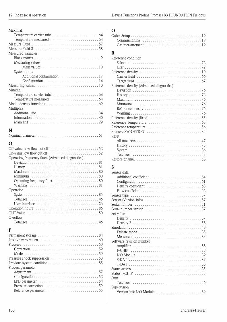
12 Index local operation Device Functions Proline Promass 83 FOUNDATION Fieldbus
100 Endress+Hauser
Maximal
Temperature carrier tube . . . . . . . . . . . . . . . . . . . . . . . 64
Temperature measured . . . . . . . . . . . . . . . . . . . . . . . . 64
Measure Fluid 1 . . . . . . . . . . . . . . . . . . . . . . . . . . . . . . . . 57
Measure Fluid 2 . . . . . . . . . . . . . . . . . . . . . . . . . . . . . . . . 58
Measured variables
Block matrix . . . . . . . . . . . . . . . . . . . . . . . . . . . . . . . . . 9
Measuring values
Main values . . . . . . . . . . . . . . . . . . . . . . . . . . . . . 10
System units
Additional configuration . . . . . . . . . . . . . . . . . . . 17
Configuration . . . . . . . . . . . . . . . . . . . . . . . . . . . 14
Measuring values . . . . . . . . . . . . . . . . . . . . . . . . . . . . . . . 10
Minimal
Temperature carrier tube . . . . . . . . . . . . . . . . . . . . . . . 64
Temperature measured . . . . . . . . . . . . . . . . . . . . . . . . 64
Mode (density function) . . . . . . . . . . . . . . . . . . . . . . . . . . 69
Multiplex
Additional line . . . . . . . . . . . . . . . . . . . . . . . . . . . . . . . 34
Information line . . . . . . . . . . . . . . . . . . . . . . . . . . . . . . 40
Main line . . . . . . . . . . . . . . . . . . . . . . . . . . . . . . . . . . . 29
NNominal diameter . . . . . . . . . . . . . . . . . . . . . . . . . . . . . . . 61
OOff-value Low flow cut off . . . . . . . . . . . . . . . . . . . . . . . . . 52
On-value low flow cut off . . . . . . . . . . . . . . . . . . . . . . . . . 52
Operating frequency fluct. (Advanced diagnostics)
Deviation . . . . . . . . . . . . . . . . . . . . . . . . . . . . . . . . . . . 81
History . . . . . . . . . . . . . . . . . . . . . . . . . . . . . . . . . . . . 81
Maximum . . . . . . . . . . . . . . . . . . . . . . . . . . . . . . . . . . 80
Minimum . . . . . . . . . . . . . . . . . . . . . . . . . . . . . . . . . . 80
Operating frequency fluct. . . . . . . . . . . . . . . . . . . . . . . 80
Warning . . . . . . . . . . . . . . . . . . . . . . . . . . . . . . . . . . . 81
Operation
System . . . . . . . . . . . . . . . . . . . . . . . . . . . . . . . . . . . . . 85
Totalizer . . . . . . . . . . . . . . . . . . . . . . . . . . . . . . . . . . . 46
User interface . . . . . . . . . . . . . . . . . . . . . . . . . . . . . . . 26
Operation hours . . . . . . . . . . . . . . . . . . . . . . . . . . . . . . . . 86
OUT Value . . . . . . . . . . . . . . . . . . . . . . . . . . . . . . . . . . . . 50
Overflow
Totalizer . . . . . . . . . . . . . . . . . . . . . . . . . . . . . . . . . . . 46
PPermanent storage . . . . . . . . . . . . . . . . . . . . . . . . . . . . . . . 84
Positive zero return . . . . . . . . . . . . . . . . . . . . . . . . . . . . . . 60
Pressure . . . . . . . . . . . . . . . . . . . . . . . . . . . . . . . . . . . . . . 59
Correction . . . . . . . . . . . . . . . . . . . . . . . . . . . . . . . . . . 59
Mode . . . . . . . . . . . . . . . . . . . . . . . . . . . . . . . . . . . . . 59
Pressure shock suppression . . . . . . . . . . . . . . . . . . . . . . . . 53
Previous system condition . . . . . . . . . . . . . . . . . . . . . . . . . 85
Process parameter
Adjustment . . . . . . . . . . . . . . . . . . . . . . . . . . . . . . . . . 57
Configuration . . . . . . . . . . . . . . . . . . . . . . . . . . . . . . . . 52
EPD parameter . . . . . . . . . . . . . . . . . . . . . . . . . . . . . . 54
Pressure correction . . . . . . . . . . . . . . . . . . . . . . . . . . . 59
Reference parameter . . . . . . . . . . . . . . . . . . . . . . . . . . 55
QQuick Setup . . . . . . . . . . . . . . . . . . . . . . . . . . . . . . . . . . . .19
Commissioning . . . . . . . . . . . . . . . . . . . . . . . . . . . . . .19
Gas measurement . . . . . . . . . . . . . . . . . . . . . . . . . . . . .19
RReference condition
Selection . . . . . . . . . . . . . . . . . . . . . . . . . . . . . . . . . . .72
User . . . . . . . . . . . . . . . . . . . . . . . . . . . . . . . . . . . . . . .72
Reference density . . . . . . . . . . . . . . . . . . . . . . . . . . . . . . . .10
Carrier fluid . . . . . . . . . . . . . . . . . . . . . . . . . . . . . . . . .66
Target fluid . . . . . . . . . . . . . . . . . . . . . . . . . . . . . . . . .67
Reference density (Advanced diagnostics)
Deviation . . . . . . . . . . . . . . . . . . . . . . . . . . . . . . . . . . .76
History . . . . . . . . . . . . . . . . . . . . . . . . . . . . . . . . . . . . .76
Maximum . . . . . . . . . . . . . . . . . . . . . . . . . . . . . . . . . .76
Minimum . . . . . . . . . . . . . . . . . . . . . . . . . . . . . . . . . . .76
Reference density . . . . . . . . . . . . . . . . . . . . . . . . . . . . .76
Warning . . . . . . . . . . . . . . . . . . . . . . . . . . . . . . . . . . . .76
Reference density (fixed) . . . . . . . . . . . . . . . . . . . . . . . . . .55
Reference Temperature . . . . . . . . . . . . . . . . . . . . . . . . . . .68
Reference temperature . . . . . . . . . . . . . . . . . . . . . . . . . . . .56
Remove SW-OPTION . . . . . . . . . . . . . . . . . . . . . . . . . . . .84
Reset
All totalizers . . . . . . . . . . . . . . . . . . . . . . . . . . . . . . . . .47
History . . . . . . . . . . . . . . . . . . . . . . . . . . . . . . . . . . . . .73
System . . . . . . . . . . . . . . . . . . . . . . . . . . . . . . . . . . . . .86
Totalizer . . . . . . . . . . . . . . . . . . . . . . . . . . . . . . . . . . .45
Restore original . . . . . . . . . . . . . . . . . . . . . . . . . . . . . . . . .58
SSensor data
Additional coefficient . . . . . . . . . . . . . . . . . . . . . . . . . .64
Configuration . . . . . . . . . . . . . . . . . . . . . . . . . . . . . . . .61
Density coefficient . . . . . . . . . . . . . . . . . . . . . . . . . . . .63
Flow coefficient . . . . . . . . . . . . . . . . . . . . . . . . . . . . . .62
Sensor type . . . . . . . . . . . . . . . . . . . . . . . . . . . . . . . . . . . .87
Sensor (Version-info) . . . . . . . . . . . . . . . . . . . . . . . . . . . . .87
Serial number . . . . . . . . . . . . . . . . . . . . . . . . . . . . . . . . . .51
Serial number sensor . . . . . . . . . . . . . . . . . . . . . . . . . . . . .87
Set value
Density 1 . . . . . . . . . . . . . . . . . . . . . . . . . . . . . . . . . . .57
Density 2 . . . . . . . . . . . . . . . . . . . . . . . . . . . . . . . . . . .58
Simulation . . . . . . . . . . . . . . . . . . . . . . . . . . . . . . . . . . . . .49
Failsafe mode . . . . . . . . . . . . . . . . . . . . . . . . . . . . . . . .85
Measurand . . . . . . . . . . . . . . . . . . . . . . . . . . . . . . . . . .85
Software revision number
Amplifier . . . . . . . . . . . . . . . . . . . . . . . . . . . . . . . . . . .88
F-CHIP . . . . . . . . . . . . . . . . . . . . . . . . . . . . . . . . . . . .89
I/O Module . . . . . . . . . . . . . . . . . . . . . . . . . . . . . . . . .89
S-DAT . . . . . . . . . . . . . . . . . . . . . . . . . . . . . . . . . . . . .87
T-DAT . . . . . . . . . . . . . . . . . . . . . . . . . . . . . . . . . . . . .88
Status access . . . . . . . . . . . . . . . . . . . . . . . . . . . . . . . . . . .25
Status F-CHIP . . . . . . . . . . . . . . . . . . . . . . . . . . . . . . . . . .88
Sum
Totalizer . . . . . . . . . . . . . . . . . . . . . . . . . . . . . . . . . . .46
Supervision
Version-info I/O Module . . . . . . . . . . . . . . . . . . . . . . .89

Device Functions Proline Promass 83 FOUNDATION Fieldbus 12 Index local operation
Endress+Hauser 101
System
Configuration . . . . . . . . . . . . . . . . . . . . . . . . . . . . . . . 84
Operation . . . . . . . . . . . . . . . . . . . . . . . . . . . . . . . . . . 85
Operation hours . . . . . . . . . . . . . . . . . . . . . . . . . . . . . 86
Reset . . . . . . . . . . . . . . . . . . . . . . . . . . . . . . . . . . . . . 86
System condition
Actual . . . . . . . . . . . . . . . . . . . . . . . . . . . . . . . . . . . . . 85
Previous . . . . . . . . . . . . . . . . . . . . . . . . . . . . . . . . . . . 85
System parameter
Configuration . . . . . . . . . . . . . . . . . . . . . . . . . . . . . . . 60
System units
Additional configuration . . . . . . . . . . . . . . . . . . . . . . . 17
Configuration . . . . . . . . . . . . . . . . . . . . . . . . . . . . . . . 14
TTarget mass flow . . . . . . . . . . . . . . . . . . . . . . . . . . . . . . . 11
Target volume flow . . . . . . . . . . . . . . . . . . . . . . . . . . . . . 11
T-DAT Save/Load . . . . . . . . . . . . . . . . . . . . . . . . . . . . . . 19
Temperature . . . . . . . . . . . . . . . . . . . . . . . . . . . . . . . . . . 10
Coefficient
KM . . . . . . . . . . . . . . . . . . . . . . . . . . . . . . . . . . 62
KM2 . . . . . . . . . . . . . . . . . . . . . . . . . . . . . . . . . 62
KT . . . . . . . . . . . . . . . . . . . . . . . . . . . . . . . . . . . 62
Temperature (Advanced diagnostics)
Deviation . . . . . . . . . . . . . . . . . . . . . . . . . . . . . . . . . . 77
History . . . . . . . . . . . . . . . . . . . . . . . . . . . . . . . . . . . . 77
Maximum . . . . . . . . . . . . . . . . . . . . . . . . . . . . . . . . . 77
Minimum . . . . . . . . . . . . . . . . . . . . . . . . . . . . . . . . . . 77
Temperature . . . . . . . . . . . . . . . . . . . . . . . . . . . . . . . . 77
Warning level . . . . . . . . . . . . . . . . . . . . . . . . . . . . . . . 77
Test display . . . . . . . . . . . . . . . . . . . . . . . . . . . . . . . . . . . 26
Totalizer
Assign . . . . . . . . . . . . . . . . . . . . . . . . . . . . . . . . . . . . . 44
Configuration . . . . . . . . . . . . . . . . . . . . . . . . . . . . . . . 44
Handling Totalizer . . . . . . . . . . . . . . . . . . . . . . . . . . . 47
Operation . . . . . . . . . . . . . . . . . . . . . . . . . . . . . . . . . . 46
Overflow . . . . . . . . . . . . . . . . . . . . . . . . . . . . . . . . . . 46
Reset . . . . . . . . . . . . . . . . . . . . . . . . . . . . . . . . . . . . . 45
Sum . . . . . . . . . . . . . . . . . . . . . . . . . . . . . . . . . . . . . . 46
Totalizer Mode . . . . . . . . . . . . . . . . . . . . . . . . . . . . . . 45
Unit . . . . . . . . . . . . . . . . . . . . . . . . . . . . . . . . . . . . . . 45
Totalizer Mode . . . . . . . . . . . . . . . . . . . . . . . . . . . . . . . . . 45
Tube damping fluct. (Advanced diagnostics)
Deviation . . . . . . . . . . . . . . . . . . . . . . . . . . . . . . . . . . 82
History . . . . . . . . . . . . . . . . . . . . . . . . . . . . . . . . . . . . 82
Maximum . . . . . . . . . . . . . . . . . . . . . . . . . . . . . . . . . 82
Minimum . . . . . . . . . . . . . . . . . . . . . . . . . . . . . . . . . . 82
Tube damping fluct. . . . . . . . . . . . . . . . . . . . . . . . . . . 81
Warning . . . . . . . . . . . . . . . . . . . . . . . . . . . . . . . . . . . 82
Tube damping (Advanced diagnostics)
Deviation . . . . . . . . . . . . . . . . . . . . . . . . . . . . . . . . . . 78
History . . . . . . . . . . . . . . . . . . . . . . . . . . . . . . . . . . . . 78
Maximum . . . . . . . . . . . . . . . . . . . . . . . . . . . . . . . . . 78
Minimum . . . . . . . . . . . . . . . . . . . . . . . . . . . . . . . . . . 78
Tube damping . . . . . . . . . . . . . . . . . . . . . . . . . . . . . . 78
Warning . . . . . . . . . . . . . . . . . . . . . . . . . . . . . . . . . . . 78
Type
I/O Module . . . . . . . . . . . . . . . . . . . . . . . . . . . . . . . . 89
UUnit
Corrected volume . . . . . . . . . . . . . . . . . . . . . . . . . . . . 16
Corrected volume flow . . . . . . . . . . . . . . . . . . . . . . . . 16
Density . . . . . . . . . . . . . . . . . . . . . . . . . . . . . . . . . . . . 17
Length . . . . . . . . . . . . . . . . . . . . . . . . . . . . . . . . . . . . 18
Mass . . . . . . . . . . . . . . . . . . . . . . . . . . . . . . . . . . . . . . 14
Mass flow . . . . . . . . . . . . . . . . . . . . . . . . . . . . . . . . . . 14
Pressure . . . . . . . . . . . . . . . . . . . . . . . . . . . . . . . . . . . 18
Reference density . . . . . . . . . . . . . . . . . . . . . . . . . . . . 17
Temperature . . . . . . . . . . . . . . . . . . . . . . . . . . . . . . . . 17
Totalizer . . . . . . . . . . . . . . . . . . . . . . . . . . . . . . . . . . . 45
Volume . . . . . . . . . . . . . . . . . . . . . . . . . . . . . . . . . . . . 15
Volume flow . . . . . . . . . . . . . . . . . . . . . . . . . . . . . . . . 15
Unlocking/locking (User interface) . . . . . . . . . . . . . . . . . . 24
User interface
Control . . . . . . . . . . . . . . . . . . . . . . . . . . . . . . . . . . . . 23
Information line . . . . . . . . . . . . . . . . . . . . . . . . . . . . . 37
VValue simulation
Measurand . . . . . . . . . . . . . . . . . . . . . . . . . . . . . . . . . 86
Version-info
Amplifier . . . . . . . . . . . . . . . . . . . . . . . . . . . . . . . . . . . 88
F-CHIP . . . . . . . . . . . . . . . . . . . . . . . . . . . . . . . . . . . . 88
I/O Module . . . . . . . . . . . . . . . . . . . . . . . . . . . . . . . . 89
Sensor . . . . . . . . . . . . . . . . . . . . . . . . . . . . . . . . . . . . . 87
Volume flow . . . . . . . . . . . . . . . . . . . . . . . . . . . . . . . . . . . 10
WWarning mode . . . . . . . . . . . . . . . . . . . . . . . . . . . . . . . . . 72
Write protect . . . . . . . . . . . . . . . . . . . . . . . . . . . . . . . . . . 49
ZZero point . . . . . . . . . . . . . . . . . . . . . . . . . . . . . . . . . . . . 61
Zero point adjustment . . . . . . . . . . . . . . . . . . . . . . . . . . . . 57
Symbols% Black liquor . . . . . . . . . . . . . . . . . . . . . . . . . . . . . . . . . 13
% Carrier mass flow . . . . . . . . . . . . . . . . . . . . . . . . . . . . . 12
% Carrier volume flow . . . . . . . . . . . . . . . . . . . . . . . . . . . 12
% Target mass flow . . . . . . . . . . . . . . . . . . . . . . . . . . . . . . 11
% Target volume flow . . . . . . . . . . . . . . . . . . . . . . . . . . . . 11
°Api . . . . . . . . . . . . . . . . . . . . . . . . . . . . . . . . . . . . . . . . . 13
°Balling . . . . . . . . . . . . . . . . . . . . . . . . . . . . . . . . . . . . . . 13
°Baume . . . . . . . . . . . . . . . . . . . . . . . . . . . . . . . . . . . . . . 13
°Brix . . . . . . . . . . . . . . . . . . . . . . . . . . . . . . . . . . . . . . . . 13
°Plato . . . . . . . . . . . . . . . . . . . . . . . . . . . . . . . . . . . . . . . . 13
Numerics100% Value
Additional line . . . . . . . . . . . . . . . . . . . . . . . . . . . . . . 32
Additional line (Multiplex) . . . . . . . . . . . . . . . . . . . . . 35
Information line . . . . . . . . . . . . . . . . . . . . . . . . . . . . . 38
Information line (Multiplex) . . . . . . . . . . . . . . . . . . . . 41
Main line . . . . . . . . . . . . . . . . . . . . . . . . . . . . . . . . . . 28
Main line (Multiplex) . . . . . . . . . . . . . . . . . . . . . . . . . 30

12 Index local operation Device Functions Proline Promass 83 FOUNDATION Fieldbus
102 Endress+Hauser

Device Functions Proline Promass 83 FOUNDATION Fieldbus Table of contents for FOUNDATION Fieldbus
Endress+Hauser 103
Table of contents for FOUNDATION Fieldbus
1 Operation via
FOUNDATION Fieldbus. . . . . . . . . . 104
1.1 Block model . . . . . . . . . . . . . . . . . . . . . . . . . . . . . 104
2 Resource Block. . . . . . . . . . . . . . . . . 106
2.1 Selecting the operating mode . . . . . . . . . . . . . . . . 106
2.2 Block status . . . . . . . . . . . . . . . . . . . . . . . . . . . . . 106
2.3 Write protection and simulation . . . . . . . . . . . . . . 106
2.4 Alarm detection and processing . . . . . . . . . . . . . . 107
2.5 Resource Block parameters . . . . . . . . . . . . . . . . . . 108
3 Transducer Block . . . . . . . . . . . . . . 109
3.1 Signal processing . . . . . . . . . . . . . . . . . . . . . . . . . 110
3.2 Important functions and parameters
of the Transducer Blocks . . . . . . . . . . . . . . . . . . . 111
3.2.1 Block output values . . . . . . . . . . . . . . . . . 111
3.2.2 Selecting the operating mode . . . . . . . . . . 112
3.2.3 Alarm detection and processing . . . . . . . . 112
3.2.4 Diagnosis . . . . . . . . . . . . . . . . . . . . . . . . . 113
3.2.5 Accessing the device-specific parameters. . 113
3.3 "Flow" Transducer Block parameters. . . . . . . . . . . 113
3.4 "Diagnosis" Transducer Block parameters . . . . . . . 131
3.5 "Display" Transducer Block parameters . . . . . . . . . 134
3.6 "Totalizer" Transducer Block parameters . . . . . . . . 151
3.7 "Calculated Density" Transducer Block parameters 155
3.8 "Viscosity" Transducer Block parameters . . . . . . . . 166
3.9 "Advanced Diagnostics"
Transducer Block parameters . . . . . . . . . . . . . . . . 169
4 Function blocks . . . . . . . . . . . . . . . . 180
5 Analog Input function block . . . . . . . 181
5.1 Signal processing . . . . . . . . . . . . . . . . . . . . . . . . . 181
5.2 Important functions and parameters of the
Analog Input function blocks . . . . . . . . . . . . . . . . 183
5.2.1 Selecting the operating mode . . . . . . . . . . 183
5.2.2 Assignment of the process variable . . . . . . 183
5.2.3 Linearization types . . . . . . . . . . . . . . . . . . 183
5.2.4 Selection of units . . . . . . . . . . . . . . . . . . . 184
5.2.5 Status of the output value OUT. . . . . . . . . 184
5.2.6 Simulation of input/output . . . . . . . . . . . . 185
5.2.7 Diagnosis . . . . . . . . . . . . . . . . . . . . . . . . . 185
5.2.8 Rescaling the input value . . . . . . . . . . . . . 185
5.2.9 Limit values . . . . . . . . . . . . . . . . . . . . . . . 186
5.2.10 Alarm detection and processing . . . . . . . . 186
6 Discrete Output function block . . . . . 188
6.1 Signal processing. . . . . . . . . . . . . . . . . . . . . . . . . . 188
6.2 Important functions and parameters of
the Discrete Output function block . . . . . . . . . . . . 189
6.2.1 Selecting the operating mode . . . . . . . . . . 189
6.2.2 Safety behavior . . . . . . . . . . . . . . . . . . . . . 189
6.2.3 Assignment between the Discrete Output
function block and the Transducer Block. . 189
6.2.4 Values for the parameters CAS_IN_D,
RCAS_IN_D, OUT_D, and SP_D . . . . . . . 190
7 Additional function blocks. . . . . . . . . 192
8 Factory settings . . . . . . . . . . . . . . . . . 193
8.1 SI units (not for USA and Canada). . . . . . . . . . . . . 193
8.1.1 Low flow cut off, full scale value,
pulse value . . . . . . . . . . . . . . . . . . . . . . . . 193
8.1.2 Language . . . . . . . . . . . . . . . . . . . . . . . . 193
8.1.3 Density, length, temperature. . . . . . . . . . . 194
8.2 US units (only for USA and Canada) . . . . . . . . . . . 194
8.2.1 Low flow cut off, full scale value,
pulse value . . . . . . . . . . . . . . . . . . . . . . . . 194
8.2.2 Language, density, length, temperature . . . 194
9 Index FOUNDATION Fieldbus . . . . . 195
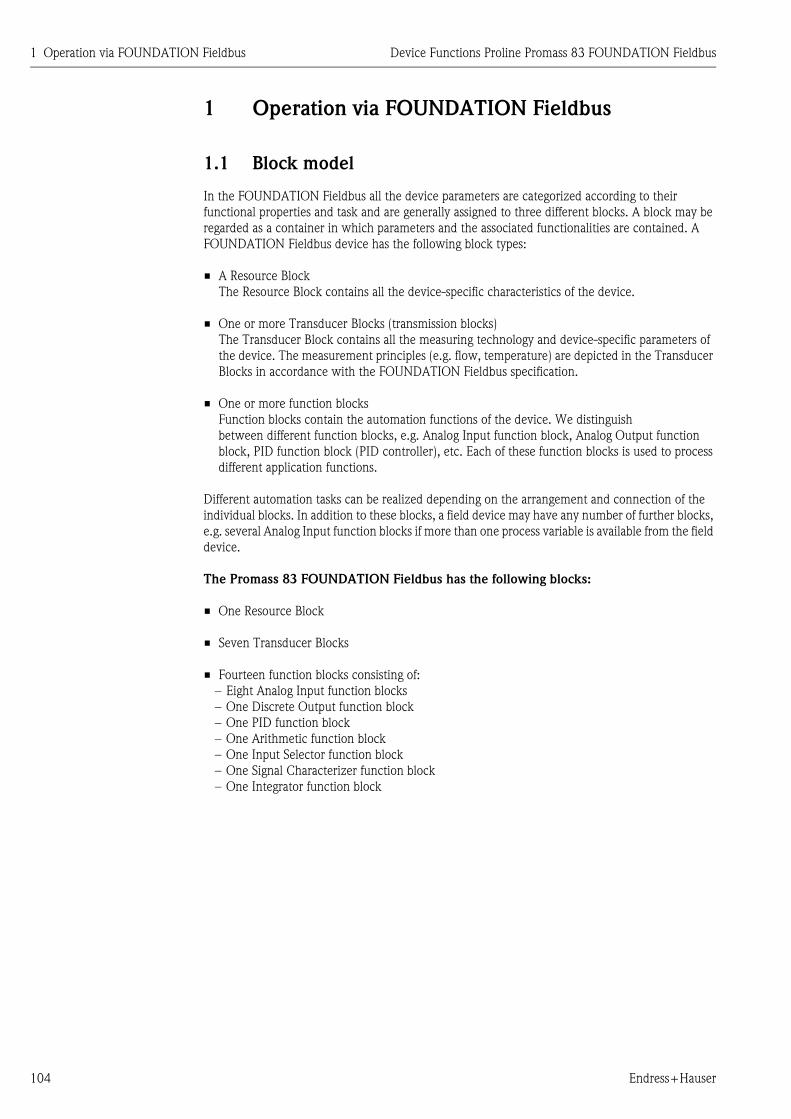
1 Operation via FOUNDATION Fieldbus Device Functions Proline Promass 83 FOUNDATION Fieldbus
104 Endress+Hauser
1 Operation via FOUNDATION Fieldbus
1.1 Block model
In the FOUNDATION Fieldbus all the device parameters are categorized according to their
functional properties and task and are generally assigned to three different blocks. A block may be
regarded as a container in which parameters and the associated functionalities are contained. A
FOUNDATION Fieldbus device has the following block types:
• A Resource Block
The Resource Block contains all the device-specific characteristics of the device.
• One or more Transducer Blocks (transmission blocks)
The Transducer Block contains all the measuring technology and device-specific parameters of
the device. The measurement principles (e.g. flow, temperature) are depicted in the Transducer
Blocks in accordance with the FOUNDATION Fieldbus specification.
• One or more function blocks
Function blocks contain the automation functions of the device. We distinguish
between different function blocks, e.g. Analog Input function block, Analog Output function
block, PID function block (PID controller), etc. Each of these function blocks is used to process
different application functions.
Different automation tasks can be realized depending on the arrangement and connection of the
individual blocks. In addition to these blocks, a field device may have any number of further blocks,
e.g. several Analog Input function blocks if more than one process variable is available from the field
device.
The Promass 83 FOUNDATION Fieldbus has the following blocks:
• One Resource Block
• Seven Transducer Blocks
• Fourteen function blocks consisting of:
– Eight Analog Input function blocks
– One Discrete Output function block
– One PID function block
– One Arithmetic function block
– One Input Selector function block
– One Signal Characterizer function block
– One Integrator function block

Device Functions Proline Promass 83 FOUNDATION Fieldbus 1 Operation via FOUNDATION Fieldbus
Endress+Hauser 105
A0004759-EN
Fig. 1 : Promass 83 FOUNDATION Fieldbus blocks
The sensor signal is first prepared specifically for the flow in the measuring block (the Transducer
Block). The process variables are then passed to the Analog Input function blocks for technical
processing (e.g. scaling, limit value processing).
The process variables go through the complete function block algorithm and are available to other
function blocks, e.g. the PID block, as a starting variable for connecting the desired application
function.
Using the Discrete Output function block (DO), various actions and functions in the
Device Functions Proline Promass 83 FOUNDATION Fieldbus can be initiated and controlled via
FOUNDATION Fieldbus.
! Note!
Additional function blocks such as the PID, Arithmetic, Input Selector, Signal Characterizer and
Integrator function block are described in the "FOUNDATION Fieldbus Overview" (BA013S)
Operating Instructions (available at: → www.endress.com → download).
Esc
E- +
Esc
E- +
Esc
- +
Esc
- +TransducerBlock
ResourceBlock
Analog InputFunction Block
PIDBlock
ARITHMETICBlock
INPUTBlock
SIGNALBlock
INTEGRATORBlock
FOUNDATIONFieldbus Discrete Output
Block

2 Resource Block Device Functions Proline Promass 83 FOUNDATION Fieldbus
106 Endress+Hauser
2 Resource Block
A Resource Block contains all the data that uniquely identifies and characterizes the field device. It
is an electronic version of a nameplate on the field device. Parameters of the Resource Block include
device type, device name, manufacturer ID, serial number, etc.
A further task of the Resource Blocks is the management of overall parameters and functions that
have an influence on the execution of the remaining blocks in the field device. The Resource Block
is thus the central unit that also checks the device status and thereby influences or controls the
operability of the other blocks and thus also of the device. Since the Resource Block has no block
input and block output data, it cannot be linked with other blocks.
The most important functions and parameters of the Resource Block are listed below; you will find
an overview of all the available parameters starting on page 108.
2.1 Selecting the operating mode
The operating mode is configured via the MODE_BLK parameter group. The Resource Block
supports the following operating modes:
! Note!
The block status OOS is also shown via the parameter BLOCK_ERR.In operating mode OOS, if write
protection is not enabled, you can access all the write parameters without restriction.
2.2 Block status
The current operating status of the Resource Block is shown in the parameter RS_STATE.
The Resource Block can take on the following states:
2.3 Write protection and simulation
Write protection of the device parameters and simulation in the Analog Input and Discrete Output
Function Block can be locked or unlocked via a jumper setting on the FOUNDATION Fieldbus
I/O board (→ Operating Instructions, Proline Promass 83 FOUNDATION Fieldbus, BA065D).
• AUTO (automatic mode)
• OOS (out of service)
• STANDBY The Resource Block is in the OOS mode.
It is not possible to execute the remaining blocks.
• ONLINE LINKING The connections configured between the function blocks have not
yet been linked.
• ONLINE Normal operating status, the Resource Block is in the AUTO
operating mode. The configured connections between the function
blocks have been established.

Device Functions Proline Promass 83 FOUNDATION Fieldbus 2 Resource Block
Endress+Hauser 107
The parameter WRITE_LOCK shows the status of the hardware write protection. The following
statuses are possible:
The parameter BLOCK_ERR indicates whether a simulation is possible in the Analog Input and
Discrete Output function block.
2.4 Alarm detection and processing
Process alarms provide information on particular block statuses and block events. The status of the
process alarms is communicated to the fieldbus host system via the parameter BLOCK_ALM. The
parameter ACK_OPTION specifies whether an alarm must be acknowledged via the fieldbus host
system.
The following process alarms are generated by the Resource Block:
Block process alarms
The following block process alarms of the Resource Block are shown via the parameter
BLOCK_ALM:
• OUT OF SERVICE
• SIMULATE ACTVE
Write protection process alarm
If write protection is disabled on the FOUNDATION Fieldbus I/O board, then prior to
communicating the change of status to the fieldbus host system the alarm priority specified in the
parameter WRITE_PRI is checked. The alarm priority specifies the action taken when the write
protection alarm WRITE_ALM is enabled.
! Note!
• If the option of a process alarm has not been enabled in the parameter ACK_OPTION, this
process alarm only has to be acknowledged in the parameter BLOCK_ALM.
• The parameter ALARM_SUM shows the current status of all the process alarms.
• LOCKED Device data cannot be modified via the FOUNDATION Fieldbus
interface.
• NOT LOCKED Device data can be modified via the FOUNDATION Fieldbus
interface.
• Simulation Active Simulation possible in the Analog Input function block via the
SIMULATE parameter and in the Discrete Output function block
via the SIMULATE_D parameter.

2 Resource Block Device Functions Proline Promass 83 FOUNDATION Fieldbus
108 Endress+Hauser
2.5 Resource Block parameters
The following table shows the Endress+Hauser-specific parameters of the Resource Block.
! Note!
FOUNDATION Fieldbus parameters are described in the Operating Instructions "FOUNDATION
Fieldbus Overview" (BA013S) (available at: → www.endress.com → download).
Resource Block
Parameter
Write access
with operating
mode
(MODE_BLK)
Description
Sensor - Serial Number read only Use this function to view the sensor serial number.
Amp. - HW Rev.Number read only Use this parameter to view the hardware revision number of the
amplifier.
Amp. - HW Identification read only Use this parameter to view the hardware ID number of the amplifier.
Amp. - SW Rev.Number read only Use this function to view the software revision number of the
amplifier.
Amp. - SW Identification read only Use this function to view the software ID number of the amplifier.
Amp. - Prod.-Number read only Use this parameter to view the production number of the amplifier.
Amp. - SW-Rev.No.
T-DAT
read only Use this parameter to view the software revision number of the
software used to create the content of the T-DAT.
Amp. - Language Group read only Use this function to view the language group.
I/O - Type read only Use this function to view the I/O module type.
I/O - HW Rev.Number read only Use this function to view the hardware revision number of the
I/O module.
I/O - HW Identification read only Use this parameter to view the hardware ID number of the
I/O module.
I/O - SW Rev.Number read only Use this function to view the software revision number of the
I/O module.
I/O - SW Identification read only Use this parameter to view the software ID number of the
I/O module.
I/O - Prod.Number read only Use this function to view the production number of the I/O module.
Device Software read only Use this function to view the device software version.

Device Functions Proline Promass 83 FOUNDATION Fieldbus 3 Transducer Block
Endress+Hauser 109
3 Transducer Block
The Transducer Blocks contain all the measurement- and device-specific parameters of the
flowmeter. All the settings directly connected with the flow measurement/application are made
here. They form the interface between the sensor-specific measured value preprocessing and the
Analog Input function blocks required for automation.
A Transducer Block allows you to influence the input and output values of a function block. The
parameters of a Transducer Block include information on the sensor type, sensor configuration,
physical units, calibration, damping, diagnosis, etc. as well as the device-specific parameters. The
device-specific parameters and functions are split into several Transducer Blocks, each covering
different task areas.
"Flow" Transducer Block/base index 1400:
This block contains all the flow-specific parameters and functions, e.g. calibration functions, sensor
data, etc. → Page 113
"Diagnosis" Transducer Block/base index 1600:
This block contains all the parameters for system diagnosis, e.g. current system status etc.
→ Page 113
"Display" Transducer Block/base index 1800:
This block contains all the parameters for configuring the local display
→ Page 134
"Totalizer" Transducer Block/base index 1900:
This block contains all the parameters for configuring the totalizers
→ Page 151
"Calculated Density" Transducer Block/base index 2000:
This block contains all the parameters for configuring density measurement
→ Page 151
"Viscosity" Transducer Block/base index 2100:
This block contains all the parameters for configuring viscosity measurement
→ Page 151
"Advanced Diagnostics" Transducer Block/base index 2200:
This block contains all the parameters for configuring advanced diagnostics
→ Page 151

3 Transducer Block Device Functions Proline Promass 83 FOUNDATION Fieldbus
110 Endress+Hauser
3.1 Signal processing
The following figure shows the internal structure of the individual Transducer Blocks:
A0004761-EN
Fig. 2 : Internal structure of the individual Transducer Blocks
The Transducer Block receives several signals from the sensor as input values (mass, density,
temperature). Other process variables (volume, standard volume) are derived from these signals.
The input signals further processed via an amplifier.
A low flow cut off allows you to hide measurement inaccuracies in the low-flow sector. The
parameter "Low Flow Cut Off - On-Value" ( → Page 118) allows you to define a limit value. If the
measured flow value is below this limit value then the output value of 0 is output.
Transducer Block “Advanced Diagnostics”
Transducer Block “Viscosity”
Transducer Block “Calculated Density”
Transducer Block “Display”
Transducer Block “Flow”
Transducer Block “Totalizer”
AI Block
Transducer Block “Diagnosis”
VolumeFlow
Temperature
Totalizer 2
S
Totalizer 3
S
Totalizer 1
S
Volume Flow
O/S
Signals
Mass Flow
CH 2
CH 6
CH 7
CH 8
CH 9
CH 1
Mass Flow
Mode_BLK
Mode_BLKTot. 2 - Assign
Tot. 3 - Assign
Tot. - Reset All
Tot. 1 - Assign
Totalizer ... - ModeTotalizer ... - Reset
Auto
Auto
Auto
O/S
Simulation -Measurand
Simulation -Value Measurand
AmplifierEsc
E- +
On Value
Low FlowCut Off
Off Value
Low Flow Cut OffPressure Shock SuppressionEmpty Pipe Detection
Positive ZeroReturn

Device Functions Proline Promass 83 FOUNDATION Fieldbus 3 Transducer Block
Endress+Hauser 111
The parameter "Simulation - Value Measurand" ( → Page 129) allows you to specify a simulation
value for the Transducer Block in order to test assigned parameters in the device and subsequent
function blocks.
In addition, the parameter "System Parameter - Positive Zero Return" ( → Page 127) allows you to
switch the measured value to "Zero Flow". This is necessary when a piping system is being cleaned,
for example.
Output variables (process variables) that are made available by the Transducer Blocks
→ chapter 3.2.1, Output Variable Block.
A process variable, e.g. mass flow, volume flow, etc., can be assigned to the individual totalizers.
Each totalizer can be manually reset using the parameter Totalizer (1 - 3) Reset.
The most important functions and parameters of the Transducer Blocks are listed below. You will
find an overview of all the available parameters starting on page 113.
3.2 Important functions and parameters
of the Transducer Blocks
3.2.1 Block output values
The Transducer Blocks make the following output variables (process variables) available. The
CHANNEL parameter in the Analog Input function block is used to assign which process variable is
read in and processed in the downstream Analog Input function block.
! Note!
The "Diagnosis" and "Display" Transducer Blocks do not have any output variables.
Block Process variable Channel parameter
(AI Block)
"Flow" Transducer Block Mass flow 1
Volume flow 2
Corrected volume flow 3
Density 4
Reference density 5
Temperature 6
"Totalizer" Transducer Block Totalizer 1 7
Totalizer 2 8
Totalizer 3 9
The following measured variables are available if the "Concentration measurement" add-on is installed in the
measuring device (order option).
"Concentration" Transducer
Block
Target fluid mass flow 40
% Target mass flow 41
Target volume flow 42
% Target volume flow 43
Corrected target volume flow 44
Carrier mass flow 45
% Carrier mass flow 46
Carrier volume flow 47
% Carrier volume flow 48
Corrected Carrier volume flow 49
% Black liquor 41
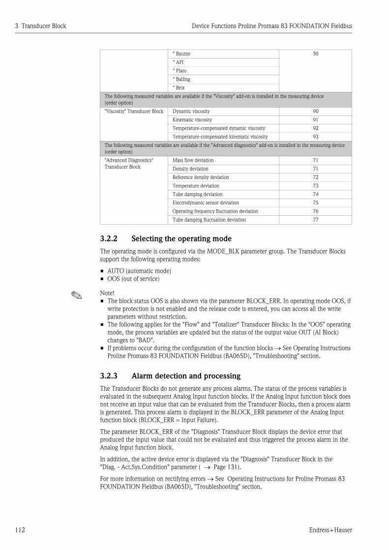
3 Transducer Block Device Functions Proline Promass 83 FOUNDATION Fieldbus
112 Endress+Hauser
3.2.2 Selecting the operating mode
The operating mode is configured via the MODE_BLK parameter group. The Transducer Blocks
support the following operating modes:
• AUTO (automatic mode)
• OOS (out of service)
! Note!
• The block status OOS is also shown via the parameter BLOCK_ERR. In operating mode OOS, if
write protection is not enabled and the release code is entered, you can access all the write
parameters without restriction.
• The following applies for the "Flow" and "Totalizer" Transducer Blocks: In the "OOS" operating
mode, the process variables are updated but the status of the output value OUT (AI Block)
changes to "BAD".
• If problems occur during the configuration of the function blocks → See Operating Instructions
Proline Promass 83 FOUNDATION Fieldbus (BA065D), "Troubleshooting" section.
3.2.3 Alarm detection and processing
The Transducer Blocks do not generate any process alarms. The status of the process variables is
evaluated in the subsequent Analog Input function blocks. If the Analog Input function block does
not receive an input value that can be evaluated from the Transducer Blocks, then a process alarm
is generated. This process alarm is displayed in the BLOCK_ERR parameter of the Analog Input
function block (BLOCK_ERR = Input Failure).
The parameter BLOCK_ERR of the "Diagnosis" Transducer Block displays the device error that
produced the input value that could not be evaluated and thus triggered the process alarm in the
Analog Input function block.
In addition, the active device error is displayed via the "Diagnosis" Transducer Block in the
"Diag. - Act.Sys.Condition" parameter ( → Page 131).
For more information on rectifying errors → See Operating Instructions for Proline Promass 83
FOUNDATION Fieldbus (BA065D), "Troubleshooting" section.
° Baume 50
° API
° Plato
° Balling
° Brix
The following measured variables are available if the "Viscosity" add-on is installed in the measuring device
(order option)
"Viscosity" Transducer Block Dynamic viscosity 90
Kinematic viscosity 91
Temperature-compensated dynamic viscosity 92
Temperature-compensated kinematic viscosity 93
The following measured variables are available if the "Advanced diagnostics" add-on is installed in the measuring device
(order option)
"Advanced Diagnostics"
Transducer Block
Mass flow deviation 71
Density deviation 71
Reference density deviation 72
Temperature deviation 73
Tube damping deviation 74
Electrodynamic sensor deviation 75
Operating frequency fluctuation deviation 76
Tube damping fluctuation deviation 77
Device Functions Proline Promass 83 FOUNDATION Fieldbus 3 Transducer Block
Endress+Hauser 113
3.2.4 Diagnosis
The status of the device is displayed via the following parameters specified in the FOUNDATION
Fieldbus specification:
• BLOCK_ERR
• Transducer Error
Detailed information on the current device status is displayed via the "Diagnosis" Transducer Block
in the manufacturer-specific parameter "Diag. - Act.Sys.Condition" ( → Page 131).
For more information on rectifying errors → See Operating Instructions for Proline Promass 83
FOUNDATION Fieldbus (BA065D), "Troubleshooting" section.
3.2.5 Accessing the device-specific parameters
To access the device-specific parameters the following requirements must be met:
1. Hardware write protection must be deactivated → See Operating Instructions for Proline
Promass 83 FOUNDATION Fieldbus (BA065D).
2. The correct code must be entered in the parameter
"Access - Code" via the corresponding Transducer Block.
3.3 "Flow" Transducer Block parameters
The following table shows the Endress+Hauser-specific parameters of the "Flow" Transducer Block.
These can only be changed after entering a release code in the "Access - Code" parameter.
! Note!
FOUNDATION Fieldbus parameters are described in the Operating Instructions "FOUNDATION
Fieldbus Overview" (BA013S) (available at: → www.endress.com → download).

3 Transducer Block Device Functions Proline Promass 83 FOUNDATION Fieldbus
114 Endress+Hauser
"Flow" Transducer Block / base index 1400:
Parameter
Write access
with operating
mode
(MODE_BLK)
Description
Access - Code AUTO - OOS All data of the measuring system are protected against inadvertent change.
Only when the code has been entered in this parameter can the
manufacturer-specific parameters be programmed and the device
configuration modified.
You can enable programming by entering:
• Code 83 (factory setting)
• Personal code ("Access - Def.Private Code" parameter → Page 135)
User input:
Max. 4-digit number: 0 to 9999
! Note!
• If the hardware write protection is enabled then access to the
manufacturer-specific parameters is blocked even if the right code is
entered.
• You can disable programming again by entering any number (other than
the release code) in this parameter.
• The Endress+Hauser service organization can be of assistance if you
mislay your personal code.
• Certain parameters are not accessible unless a special
service code is entered. This service code is known only to the
Endress+Hauser service organization. Please contact your
Endress+Hauser service center if you require clarification.
Access - Status read only Use this parameter to check the access status for the parameter matrix.
Display:
LOCKED (parameterization disabled)
ACCESS CUSTOMER (parameterization enabled)
ACCESS SERVICE (parameterization enabled)
System Value -
Mass Flow
read only Use this parameter to view the mass flow currently measured.
Display:
5-digit floating-point number, including unit and sign
(e.g. 462.87 kg/h; –731.63 lb/min; etc.)
System Unit -
Mass Flow
AUTO - OOS Use this parameter to select the unit for the mass flow (mass/time).
The unit you select here is also valid for:
• Simulation
• Low flow cut off
Options:
Metric:
Gram → g/s; g/min; g/h; g/day
Kilogram → kg/s; kg/min; kg/h; kg/day
Ton → t/s; t/min; t/h; t/day
US:
Ounce → oz/s; oz/min; oz/h; oz/day
Pound → lb/s; lb/min; lb/h; lb/day
Ton → ton/s; ton/min; ton/h; ton/day
Factory setting:
Depends on nominal diameter and country → Page 193 ff.
! Note!
The unit selected here has no influence on the transmitted process variable
to the Analog Input function block.

Device Functions Proline Promass 83 FOUNDATION Fieldbus 3 Transducer Block
Endress+Hauser 115
System Value -
Volume Flow
read only Use this parameter to view the volume flow.The volume flow is derived
from the measured mass flow and the measured density of the fluid.
Display:
5-digit floating-point number, including unit and sign
(e.g. 5.5445 dm3/min; 1.4359 m3/h; –731.63 gal/d; etc.)
System Unit -
Volume Flow
AUTO - OOS Use this parameter to select the unit for the volume flow (volume/time).
The unit you select here is also valid for:
• Simulation
• Low flow cut off
Options:
Metric:
Cubic centimeter → cm3/s; cm3/min; cm3/h; cm3/day
Cubic decimeter → dm3/s; dm3/min; dm3/h; dm3/day
Cubic meter → m3/s; m3/min; m3/h; m3/day
Milliliter → ml/s; ml/min; ml/h; ml/day
Liter → l/s; l/min; l/h; l/day
Hectoliter → hl/s; hl/min; hl/h; hl/day
Megaliter → Ml/s; Ml/min; Ml/h; Ml/day
US:
Cubic centimeter → cc/s; cc/min; cc/h; cc/day
Acre foot → af/s; af/min; af/h; af/day
Cubic foot → ft3/s; ft3/min; ft3/h; ft3/day
Fluid ounce → oz f/s; oz f/min; oz f/h; oz f/day
Gallon → gal/s; gal/min; gal/h; gal/day
Kilo gallon → Kgal/s; Kgal/min; Kgal/h; Kgal/day
Million gallon → Mgal/s; Mgal/min; Mgal/h; Mgal/day
Barrel (normal fluids: 31.5 gal/bbl) → bbl/s; bbl/min; bbl/h; bbl/day
Barrel (beer: 31.0 gal/bbl) → bbl/s; bbl/min; bbl/h; bbl/day
Barrel (petrochemicals: 42.0 gal/bbl) → bbl/s; bbl/min; bbl/h; bbl/day
Barrel (filling tanks: 55.0 gal/bbl) → bbl/s; bbl/min; bbl/h; bbl/day
Imperial:
Gallon → gal/s; gal/min; gal/h; gal/day
Mega gallon → Mgal/s; Mgal/min; Mgal/h; Mgal/day
Barrel (beer: 36.0 gal/bbl) → bbl/s; bbl/min; bbl/h; bbl/day
Barrel (petrochemicals: 34.97 gal/bbl) → bbl/s; bbl/min; bbl/h; bbl/day
Factory setting:
Depends on nominal diameter and country → Page 193 ff.
! Note!
The unit selected here has no influence on the transmitted process variable
to the Analog Input function block.
System Value -
Corr.Volume Flow
read only The calculated corrected volume flow appears on the display. The calculated
corrected volume flow is derived from the measured mass flow and the
reference density of the fluid (density at reference temperature, measured or
fixed entry).
Display:
5-digit floating-point number, including unit and sign
(e.g. 1.3549 Nm3/h; 7.9846 scm/day; etc.)
"Flow" Transducer Block / base index 1400:
Parameter
Write access
with operating
mode
(MODE_BLK)
Description
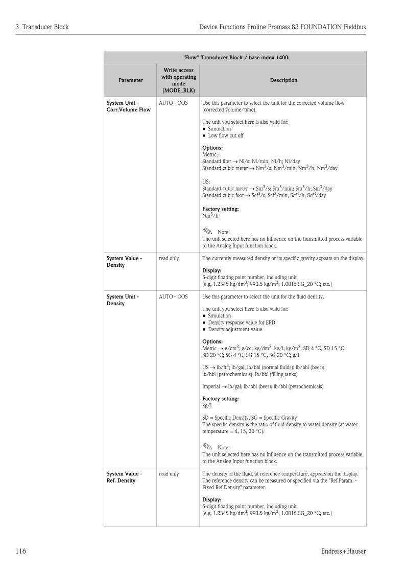
3 Transducer Block Device Functions Proline Promass 83 FOUNDATION Fieldbus
116 Endress+Hauser
System Unit -
Corr.Volume Flow
AUTO - OOS Use this parameter to select the unit for the corrected volume flow
(corrected volume/time).
The unit you select here is also valid for:
• Simulation
• Low flow cut off
Options:
Metric:
Standard liter → Nl/s; Nl/min; Nl/h; Nl/day
Standard cubic meter → Nm3/s; Nm3/min; Nm3/h; Nm3/day
US:
Standard cubic meter → Sm3/s; Sm3/min; Sm3/h; Sm3/day
Standard cubic foot → Scf3/s; Scf3/min; Scf3/h; Scf3/day
Factory setting:
Nm3/h
! Note!
The unit selected here has no influence on the transmitted process variable
to the Analog Input function block.
System Value -
Density
read only The currently measured density or its specific gravity appears on the display.
Display:
5-digit floating point number, including unit
(e.g. 1.2345 kg/dm3; 993.5 kg/m3; 1.0015 SG_20 °C; etc.)
System Unit -
Density
AUTO - OOS Use this parameter to select the unit for the fluid density.
The unit you select here is also valid for:
• Simulation
• Density response value for EPD
• Density adjustment value
Options:
Metric → g/cm3; g/cc; kg/dm3; kg/l; kg/m3; SD 4 °C, SD 15 °C,
SD 20 °C; SG 4 °C, SG 15 °C, SG 20 °C; g/l
US → lb/ft3; lb/gal; lb/bbl (normal fluids); lb/bbl (beer);
lb/bbl (petrochemicals); lb/bbl (filling tanks)
Imperial → lb/gal; lb/bbl (beer); lb/bbl (petrochemicals)
Factory setting:
kg/l
SD = Specific Density, SG = Specific Gravity
The specific density is the ratio of fluid density to water density (at water
temperature = 4, 15, 20 °C).
! Note!
The unit selected here has no influence on the transmitted process variable
to the Analog Input function block.
System Value -
Ref. Density
read only The density of the fluid, at reference temperature, appears on the display.
The reference density can be measured or specified via the "Ref.Param. -
Fixed Ref.Density" parameter.
Display:
5-digit floating point number, including unit
(e.g. 1.2345 kg/dm3; 993.5 kg/m3; 1.0015 SG_20 °C; etc.)
"Flow" Transducer Block / base index 1400:
Parameter
Write access
with operating
mode
(MODE_BLK)
Description
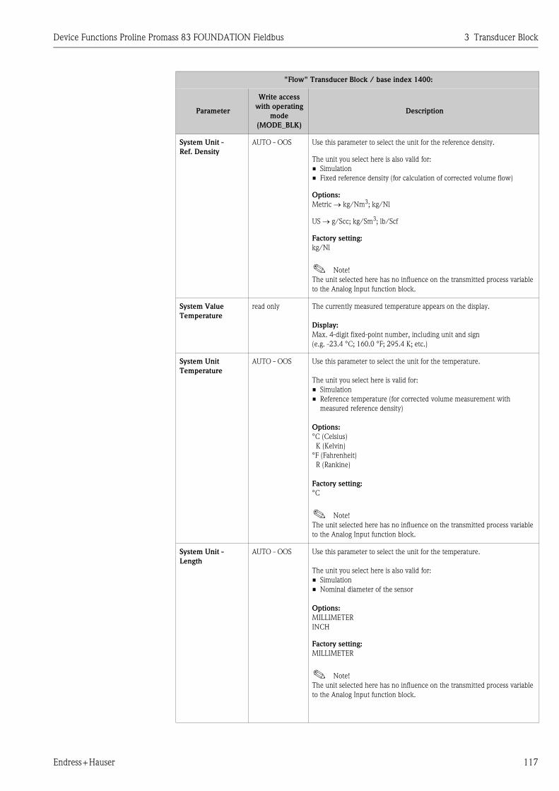
Device Functions Proline Promass 83 FOUNDATION Fieldbus 3 Transducer Block
Endress+Hauser 117
System Unit -
Ref. Density
AUTO - OOS Use this parameter to select the unit for the reference density.
The unit you select here is also valid for:
• Simulation
• Fixed reference density (for calculation of corrected volume flow)
Options:
Metric → kg/Nm3; kg/Nl
US → g/Scc; kg/Sm3; lb/Scf
Factory setting:
kg/Nl
! Note!
The unit selected here has no influence on the transmitted process variable
to the Analog Input function block.
System Value
Temperature
read only The currently measured temperature appears on the display.
Display:
Max. 4-digit fixed-point number, including unit and sign
(e.g. -23.4 °C; 160.0 °F; 295.4 K; etc.)
System Unit
Temperature
AUTO - OOS Use this parameter to select the unit for the temperature.
The unit you select here is valid for:
• Simulation
• Reference temperature (for corrected volume measurement with
measured reference density)
Options:
°C (Celsius)
K (Kelvin)
°F (Fahrenheit)
R (Rankine)
Factory setting:
°C
! Note!
The unit selected here has no influence on the transmitted process variable
to the Analog Input function block.
System Unit -
Length
AUTO - OOS Use this parameter to select the unit for the temperature.
The unit you select here is also valid for:
• Simulation
• Nominal diameter of the sensor
Options:
MILLIMETER
INCH
Factory setting:
MILLIMETER
! Note!
The unit selected here has no influence on the transmitted process variable
to the Analog Input function block.
"Flow" Transducer Block / base index 1400:
Parameter
Write access
with operating
mode
(MODE_BLK)
Description

3 Transducer Block Device Functions Proline Promass 83 FOUNDATION Fieldbus
118 Endress+Hauser
System Unit -
Pressure
AUTO - OOS Use this parameter to select the unit for pressure.
The unit you select here is also valid for:
• Simulation
• Specified pressure
Options:
bar a
bar g
psi a
psi g
Factory setting:
bar g
! Note!
The unit selected here has no influence on the transmitted process variable
to the Analog Input function block.
Low Flow Cut Off -
Assign
AUTO - OOS Use this parameter to assign the switching point for low flow cut off.
Options:
OFF
MASS FLOW
VOLUME FLOW
COR. VOLUME FLOW
Factory setting:
MASS FLOW
Low Flow Cut Off -
On-Value
AUTO - OOS Use this parameter to assign a value to the switch-on point for low flow cut off.
Low flow cut off is active if the setting is a value not equal to 0.
User input:
5-digit floating-point number
Factory setting:
Depends on nominal diameter and country → Page 193 ff.
! Note!
With low flow cut off active, the status condition of the process variable
changes to UNCERTAIN.
Low Flow Cut Off -
Unit
read only Displays the unit of the low flow cut off.
! Note!
Depending on the process variable selected, the unit is taken from the
corresponding parameter "System Unit - Mass Flow", "System Unit - Volume
Flow" or "System Unit - Cor. Volume Flow".
"Flow" Transducer Block / base index 1400:
Parameter
Write access
with operating
mode
(MODE_BLK)
Description

Device Functions Proline Promass 83 FOUNDATION Fieldbus 3 Transducer Block
Endress+Hauser 119
Low Flow Cut Off -
Off-Value
AUTO - OOS Use this function to enter the off-value (b) for low flow cut off.
Enter the off-value as a positive hysteresis (H) from the on-value (a).
User input:
Integer 0 to 100%
Factory setting:
50%
A0003882
m = On-value, n = Off-value
a Low flow cut off is switched on
b Low flow cut off is switched off (a + a ⋅ H)
H Hysteresis value: 0 to 100%
■ Low flow cut off active
Q Flow
Process - Pressure
Shock Suppression
AUTO - OOS The closure of a valve can cause brief but severe movements of the fluid in
the piping system, movements which the measuring system registers. The
pulses totaled in this way result in a totalizer reading error, particularly in
the case of filling processes. For this reason, the measuring device is
equipped with pressure shock suppression (= short-term signal suppression)
which can eliminate system-related "disruptions".
! Note!
Note that pressure shock suppression cannot be used unless the low flow cut
off is active (see parameter "Low Flow Cut Off - On-Value" → Page 118).
Use this parameter to define the time span for active pressure shock
suppression.
(Continued on next page)
"Flow" Transducer Block / base index 1400:
Parameter
Write access
with operating
mode
(MODE_BLK)
Description
t
H
Q
m
nb
a

3 Transducer Block Device Functions Proline Promass 83 FOUNDATION Fieldbus
120 Endress+Hauser
Process - Pressure
Shock Suppression
(continued)
AUTO - OOS Activation of the pressure shock suppression
Pressure shock suppression is activated after the flow falls below the
ON-VALUE for the low flow cut off (see point a in graphic).
While pressure shock suppression is active, the following conditions apply:
• Flow reading on display → 0
• Totalizer reading → the totalizers are pegged at the last correct value.
Deactivation of the pressure shock suppression
The pressure shock suppression is deactivated after the time interval, set in
this function, has passed (see point b in graphic).
! Note!
The actual flow value is displayed and output when the time interval for
pressure shock suppression has passed and the flow exceeds the OFF-
VALUE for the low flow cut off (see point c in graphic).
A0001285-EN
m = On-value (low flow cut off), n = Off-value (low flow cut off)
a Activated when the on-value for low flow cut off is undershot
b Deactivated once the time specified expires
c Flow values are taken into account again for calculating the pulses
■ Suppressed values
Q Flow
User input:
Max. 4-digit number, incl. unit: 0.00 to 100.0 s
Factory setting:
0.00 s
"Flow" Transducer Block / base index 1400:
Parameter
Write access
with operating
mode
(MODE_BLK)
Description
nm
a b c
inactive active inactive
t
Pressure shock suppression
Command:Valve closes
Q
Given time
After filling

Device Functions Proline Promass 83 FOUNDATION Fieldbus 3 Transducer Block
Endress+Hauser 121
Sys. - Permanent
Storage
read only This parameter indicates whether automatic, permanent storage of
parameter changes in the EEPROM is switched on or off.
Display:
OFF
ON
Factory setting:
ON
" Caution!
• The option selected in this function can only be changed by the
Endress+Hauser service organization.
• If OFF is selected, all parameter changes are not permanently stored in the
EEPROM. This means that these parameter changes are no longer
available after a power failure. In these instances, the device starts with
the parameter configurations last stored in the EEPROM.
EPD -
Empty Pipe
Detection
AUTO - OOS Use this parameter to activate the empty pipe detection (EPD). With empty
measuring tubes the density of the fluid falls below the specified value in the
"EPD - Low Value" parameter.
Options:
OFF
ON
Factory setting:
OFF
" Caution!
• Select a correspondingly low EPD response value in the "EPD - Low
Value" parameter so that the difference to the effective density of the fluid
is sufficiently large. This ensures that totally empty measuring tubes and
not partially filled ones are detected.
• For gas measurement, we strongly recommend you switch off empty pipe
detection.
EPD -
Low Value
AUTO - OOS Use this parameter to specify a lower threshold value (limit value) for the
measured density as process problems can occur if the density is too low.
User input:
5-digit floating-point number
Factory setting:
0.2000
EPD -
High Value
AUTO - OOS Use this parameter to set an upper threshold for the measured density value.
User input:
5-digit floating-point number
Factory setting:
6.0000
EPD -
Unit
read only Displays the unit of the empty pipe detection (EPD).
! Note!
The unit is taken from the parameter "System Unit - Density"
( → Page 116).
"Flow" Transducer Block / base index 1400:
Parameter
Write access
with operating
mode
(MODE_BLK)
Description

3 Transducer Block Device Functions Proline Promass 83 FOUNDATION Fieldbus
122 Endress+Hauser
EPD -
Response time
AUTO - OOS Use this parameter to enter the time span for which the criteria for an empty
pipe have to be satisfied without interruption before a notice message or
fault message is generated.
User input:
Fixed point number: 1.0 to 100.0 s
Factory setting:
1.0 s
EPD - Exc.Curr.Max AUTO - OOS Use this parameter to activate the empty pipe detection (EPD). In the event
of inhomogeneous fluids or air bubbles, the excitation current of the
measuring pipes increases. If the excitation current set in this function is
exceeded, error message #700 is output in the "Diag. -Act.Sys.Condition"
parameter ( → Page 131) in the same way as the "EPD - Low Value" and
"EPD High Value" parameter.
User input:
5-digit floating-point number
Factory setting:
100.00 mA (deactivated)
! Note!
The function is not activated until a value under 100 mA is input. Entering
the value 100 mA deactivates the function.
Ref.Param. - Corr.
Vol.Calculation
AUTO - OOS This parameter is used to set the reference density for calculating the
corrected volume flow.
Options:
CALC. REF. DENSITY
FIX. REF. DENSITY
Factory setting:
CALC. REF. DENSITY
Ref.Param. - Fixed
Ref.Density
AUTO - OOS! Note!
The entry is not active unless the FIX REF. DENSITY option was selected in
the parameter "Reference Param. - Cor. Volume Calc.".
In this parameter, a fixed value for the reference density can be entered,
with which the corrected volume flow or corrected volume is calculated.
User input:
5-digit floating-point number
Factory setting:
1.0000 kg/Nl
Ref.Param. - Fixed
Ref.Density Unit
AUTO - OOS Displays the unit used for the standard density in the calculation of corrected
volume flow.
! Note!
The unit is taken from the parameter "System Unit - Reference Density"
( → Page 129).
"Flow" Transducer Block / base index 1400:
Parameter
Write access
with operating
mode
(MODE_BLK)
Description

Device Functions Proline Promass 83 FOUNDATION Fieldbus 3 Transducer Block
Endress+Hauser 123
Ref.Param. -
Exp. Coeff.Lin.
AUTO - OOS! Note!
The entry is not active unless the CALC. REF. DENSITY option was selected
in the parameter "Reference Param. - Cor. Volume Calc.".
For calculating temperature-compensated density functions, an expansion
coefficient specific to the fluid is required which you can enter in this
parameter.
User input:
5-digit floating-point number
Factory setting:
0.5000 e-3 [1/K]
Ref.Param. -
Exp.Coeff.Square
AUTO - OOS Use this parameter to enter a squarely expansion coefficient, if the
temperature compensation follows a nonlinear behavior.
User input:
5-digit floating-point number
Factory setting:
0 e-6 [1/K2]
Ref.Param. - Ref.
Temperature
AUTO - OOS! Note!
This parameter is not active unless the CALC. REF. DENSITY option was
selected in the parameter "Ref.Param. - Corr. Vol.Calculation".
For entering the reference temperature for calculating the corrected volume
flow, the corrected volume and the reference density.
Options:
5-digit floating-point number
Factory setting:
20.000
The reference density is calculated as follows:
ρN = ρ · (1 + α Δ t + β Δ t2) ; where Δ t = t – tNρN = Reference density
ρ = Currently measured density (Promass measured value)
t = Currently measured fluid temperature (Promass measured value)
tN = Reference temperature at which the reference density should be
calculated (e.g. 20 °C)
α = Volumetric expansion coefficient of the fluid in question, unit = [1/K];
K = Kelvin
β = Quadratic volumetric expansion coefficient of the fluid in question,
unit = [1/K2]
Reference Param. -
Ref. Temperature
Unit
AUTO - OOS Displays the unit used for the temperature in the calculation of
corrected volume flow.
! Note!
The unit is taken from the parameter "System Unit - Temperature"
( → Page 117).
"Flow" Transducer Block / base index 1400:
Parameter
Write access
with operating
mode
(MODE_BLK)
Description

3 Transducer Block Device Functions Proline Promass 83 FOUNDATION Fieldbus
124 Endress+Hauser
Adj. - Zeropoint
Adjustment
AUTO - OOS This parameter enables a zero point adjustment to be automatically carried
out. The new zero point determined by the measuring system is adopted by
the "Sensor Data - Zeropoint" parameter ( → Page 127).
User input:
CANCEL
START
Factory setting:
CANCEL
" Caution!
Before carrying out an adjustment, please refer to BA065D/06/en "Promass
83 FOUNDATION Fieldbus" Operating Instructions where a detailed
description of the zero point adjustment is given.
! Note!
• Programming is locked during zero point adjustment.
• If zero point adjustment is not possible (e.g. if v > 0.1 m/s) or has been
aborted, error message #731 is displayed in the "Diag. - Act.Sys.Condition"
parameter ( → Page 131). The status of the parameter is passed on to
subsequent function blocks via the status condition UNCERTAIN of the
process variable.
• The zero point adjustment can, also using cyclic scheduled data
transmission, be controlled or initiated via the Discrete Output function
block.
Adj. -
Dense.Set.Value 1
AUTO - OOS Use this parameter to select whether a 1-point or a 2-point density
adjustment should be carried out.
Options:
CANCEL
1-POINT
2-POINT
Adj. -
Dense.Set.Value 1
AUTO - OOS In this parameter, enter the density set value of the fluid for which you want
to carry out a field density adjustment.
User input:
5-digit floating-point number
! Note!
The preset density entered here should not vary from the actual fluid density
by a more than ±10%.
Adj. - Dens.Unit read only Use this parameter to view the unit for the fluid density.
Display:
Metric → g/cm3; g/cc; kg/dm3; kg/l; kg/m3; SD 4 °C, SD 15 °C,
SD 20 °C; SG 4 °C, SG 15 °C, SG 20 °C
US → lb/ft3; lb/gal; lb/bbl (normal fluids); lb/bbl (beer);
lb/bbl (petrochemicals); lb/bbl (filling tanks)
Imperial → lb/gal; lb/bbl (beer); lb/bbl (petrochemicals)
Adj. - Meas.Fluid 1 AUTO - OOS In this parameter the actual density of the fluid is measured for the density
adjustment.
Options:
CANCEL
START
"Flow" Transducer Block / base index 1400:
Parameter
Write access
with operating
mode
(MODE_BLK)
Description

Device Functions Proline Promass 83 FOUNDATION Fieldbus 3 Transducer Block
Endress+Hauser 125
Adj. - Dens.
Adjustment
AUTO - OOS With this parameter a density adjustment can be carried out. The density
adjustment values will thus be recalculated and stored. This ensures that the
values dependent on density calculations (e.g. mass flow) are as accurate as
possible.
! Note!
Before carrying out a density adjustment, please refer to BA059D/06/en
"Promass 83 FOUNDATION Fieldbus Operating Instructions" where a
detailed description of the density adjustment is given.
Options:
CANCEL
START
Factory setting:
CANCEL
Adj. -
Dense.Set.Value 2
AUTO - OOS Use this parameter to enter the density setpoint value for the second fluid for
which you want to carry out field density adjustment.
User input:
5-digit floating-point number, incl. units
! Note!
• The preset density entered here should not vary from the actual fluid
density by a more than ±10%.
• The difference between the density setpoint values must be at least
0.2 kg/l.
• The associated unit is taken from the "System Units" parameter group.
Adj. - Meas.Fluid 2 AUTO - OOS In this parameter the current density of the second fluid is measured for
density adjustment.
Options:
CANCEL
START
Adj. -
Restore Original
AUTO - OOS With this parameter the original density coefficients determined at the
factory are restored.
Options:
NO
YES
Factory setting:
NO
Press.Corr. -
Pressure Mode
AUTO - OOS Use this parameter to configure an automatic pressure correction. In this
way, the effect of a pressure deviation between the calibration and process
pressures on the measured error for mass flow is compensated for, (see also
Operating Instructions BA065D, Accuracy Chapter).
Options:
OFF
FIX (A fixed process pressure for pressure correction is specified
→ "Press.Corr. - Pressure" parameter)
Factory setting:
OFF
"Flow" Transducer Block / base index 1400:
Parameter
Write access
with operating
mode
(MODE_BLK)
Description

3 Transducer Block Device Functions Proline Promass 83 FOUNDATION Fieldbus
126 Endress+Hauser
Press.Corr. -
Pressure
AUTO - OOS! Note!
The entry is not active unless the FIX option was selected in the "Press.Corr.
- Pressure Mode" parameter.
Use this parameter to enter the value for the process pressure which should
be used during pressure correction.
User input:
7-digit floating-point number
Factory setting:
0 bar g
! Note!
The associated unit is taken from the "System Units" parameter group.
Sys. - Install.
Direction
Sensor
AUTO - OOS Use this parameter to reverse the sign of the flow quantity, if necessary.
! Note!
Ascertain the actual direction of fluid flow with reference to the direction
indicated by the arrow on the sensor (nameplate).
Options:
NORMAL (flow as indicated by the arrow)
INVERSE (flow opposite to direction indicated by the arrow)
Factory setting:
NORMAL
Sys. - Density
Damping
AUTO - OOS The density filter allows the sensitivity of the density measuring signal to be
lowered with respect to variations in the density of the fluid, e.g. with
inhomogeneous liquids. The damping acts on all parameters and outputs of
the measuring device.
User input:
Max. 5-digit number, including unit: 0.00 to 100.00 s
Factory setting:
0.00 s
Sys. - Flow Damping AUTO - OOS Setting the filter depth of the digital filter. The sensitivity of the flow
measurement signal can be reduced with respect to interference peaks
(e.g. in the event of a high solid content, gas bubbles in the fluid etc.). The
reaction time of the measuring device increases with every increase in the
filter setting. The damping acts on all parameters and outputs of the
measuring device.
User input:
0 to 100 s
Factory setting:
0 s
"Flow" Transducer Block / base index 1400:
Parameter
Write access
with operating
mode
(MODE_BLK)
Description

Device Functions Proline Promass 83 FOUNDATION Fieldbus 3 Transducer Block
Endress+Hauser 127
Sys. - Positive Zero
Return
AUTO - OOS Use this parameter to interrupt evaluation of measured variables. This is
necessary when a piping system is being cleaned, for example. This setting
acts on all parameter and outputs of the measuring device.
Options:
OFF
ON (signal output is set to the ZERO FLOW value, temperature and density
are output normally)
Factory setting:
OFF
! Note!
• The active positive zero return is passed on to subsequent function blocks
via the status condition (UNCERTAIN) of the process variable.
• Interruption of the processing of measured values can, also using cyclic
scheduled data transmission, be controlled or initiated via the Discrete
Output function block.
Sensor Data -
K-Factor
read only This parameter shows the current calibration factor for the sensor.
Factory setting:
Depends on nominal diameter and calibration.
! Note!
If the service code is used to call this parameter, this value can be edited.
Sensor Data -
Zeropoint
read only This parameter shows the current zero-point correction value for the sensor.
Display:
Max. 5-digit number: –99999 to +99999
Factory setting:
Depends on calibration.
Sensor Data -
Nominal Diameter
read only This function shows the nominal diameter for the sensor.
Factory setting:
Depends on nominal diameter
! Note!
If the service code is used to call this parameter, this value can be edited.
Sensor Data -
Temp. Coeff.
KM
read only This function shows the temperature coefficient KM.
Sensor Data -
Temp. Coeff.
KM2
read only This function shows the temperature coefficient KM2.
Sensor Data -
Temp. Coeff. KT
read only This function shows the temperature coefficient KT.
Sensor Data -
Cal. Coeff. KD1
read only This function shows the calibration coefficient KD1.
Sensor Data -
Cal. Coeff. KD2
read only This function shows the calibration coefficient KD2.
"Flow" Transducer Block / base index 1400:
Parameter
Write access
with operating
mode
(MODE_BLK)
Description

3 Transducer Block Device Functions Proline Promass 83 FOUNDATION Fieldbus
128 Endress+Hauser
Sensor Data -
Density Coeff.
C0
read only This function shows the actual density coefficient C0.
! Note!
If the service code is used to call this parameter, this value can be edited.
" Caution!
A density adjustment can alter the calibration value of this coefficient.
Sensor Data -
Density Coeff.
C1
read only This function shows the actual density coefficient C1.
! Note!
If the service code is used to call this parameter, this value can be edited.
" Caution!
A density adjustment can alter the calibration value of this coefficient.
Sensor Data -
Density Coeff.
C2
read only This function shows the actual density coefficient C2.
! Note!
If the service code is used to call this parameter, this value can be edited.
" Caution!
A density adjustment can alter the calibration value of this coefficient.
Sensor Data -
Density Coeff.
C3
read only This function shows the actual density coefficient C3.
! Note!
If the service code is used to call this parameter, this value can be edited.
" Caution!
A density adjustment can alter the calibration value of this coefficient.
Sensor Data -
Density Coeff.
C4
read only This function shows the actual density coefficient C4.
! Note!
If the service code is used to call this parameter, this value can be edited.
" Caution!
A density adjustment can alter the calibration value of this coefficient.
Sensor Data -
Density Coeff.
C5
read only This function shows the actual density coefficient C5.
! Note!
If the service code is used to call this parameter, this value can be edited.
" Caution!
A density adjustment can alter the calibration value of this coefficient.
Sensor Data - Min.
Temp.Measured
read only The lowest fluid temperature measured appears on the display.
Sensor Data - Max.
Temp.Measured
read only The highest fluid temperature measured appears on the display.
"Flow" Transducer Block / base index 1400:
Parameter
Write access
with operating
mode
(MODE_BLK)
Description

Device Functions Proline Promass 83 FOUNDATION Fieldbus 3 Transducer Block
Endress+Hauser 129
Sensor Data - Min.
Temp.Carrier
read only The lowest carrier tube temperature measured appears on the display.
! Note!
This function is not available for the Promass E measuring device.
Sensor Data -
Max. Temp.Carrier
read only The highest carrier tube temperature measured appears on the display.
! Note!
This function is not available for the Promass E measuring device.
Sensor Data -
Temp.Unit
read only Displays the unit of the temperature.
! Note!
The unit is taken from the parameter "System Unit - Temperature"
( → Page 117).
Simulation -
Measurand
AUTO - OOS Use this parameter to set all inputs, outputs and totalizers to their defined
flow-response modes, in order to check whether they respond correctly.
During this time, the words "SIMULATION MEASURAND" appear on the
display.
Options:
OFF
MASSFLOW
VOLUMEFLOW
COR. VOLUMEFLOW
DENSITY
REFERENCE DENSITY
TEMPERATURE
Factory setting:
OFF
! Note!
The active simulation mode is passed on to subsequent function blocks via
the status condition (UNCERTAIN) of the process variable.
" Caution!
• The measuring device cannot be used for measuring while this simulation
is in progress.
• The setting is not saved if the power supply fails.
Simulation -
Value
Measurand
AUTO - OOS! Note!
The entry is not active unless a measured variable was selected in the
"Simulation - Measurand" parameter.
Use this parameter to define a selectable value (e.g. 12 m3/s). This is used to
test the associated parameters in the flowmeter itself and downstream
function blocks.
User input:
5-digit floating-point number
Factory setting:
0 [unit]
" Caution!
The setting is not saved if the power supply fails.
"Flow" Transducer Block / base index 1400:
Parameter
Write access
with operating
mode
(MODE_BLK)
Description

3 Transducer Block Device Functions Proline Promass 83 FOUNDATION Fieldbus
130 Endress+Hauser
Simulation -
Unit
read only Displays the unit used for the simulation.
! Note!
Depending on the selection in the parameter "Simulation - Measurand", the
unit is taken over from the corresponding parameter "System Unit -".
Simulation - Unit read only The current unit for the simulation value in the "Simulation - Measurand
Value" parameter appears on the display.
! Note!
The unit can be selected in the "System Unit - Volume Flow" or "System
Unit - Mass Flow" parameter ( → Page 114 ff.).
Sensor - Type read only Use this parameter to view the sensor type (e.g. Promass F).
Sensor - HW
Rev.Number
read only Use this parameter to view the hardware revision number of the sensor.
Sensor - SW
Rev.No.S-DAT
read only Use this function to view the software revision number of the software used
to create the content of the S-DAT.
Sensor - HW
Identification
read only This parameter is only used for service purposes.
Sensor -
Prod.Number
read only This parameter is only used for service purposes.
Service -
Osc.Frequency
read only This parameter is only used for service purposes.
Service -
Excitation Current
AUTO - OOS This parameter is only used for service purposes.
Service -
Carrier Tube
Temperature
AUTO - OOS This parameter is only used for service purposes.
Service -
Monitoring Mode
AUTO - OOS This parameter is only used for service purposes.
Service -
Monitoring
Osc.Amplitude
AUTO - OOS This parameter is only used for service purposes.
Service -
Monitoring
Gain Amplifier
AUTO - OOS This parameter is only used for service purposes.
Service -
Monitoring
Interval
AUTO - OOS This parameter is only used for service purposes.
Service - Gas Mode AUTO - OOS This parameter is only used for service purposes.
Service - Gas Type AUTO - OOS This parameter is only used for service purposes.
Service - Sonic
Velocity
AUTO - OOS This parameter is only used for service purposes.
Service -
Temp.Coeff.Sonic
Velocity
AUTO - OOS This parameter is only used for service purposes.
Amp. Device Type read only This parameter is only used for service purposes.
"Flow" Transducer Block / base index 1400:
Parameter
Write access
with operating
mode
(MODE_BLK)
Description
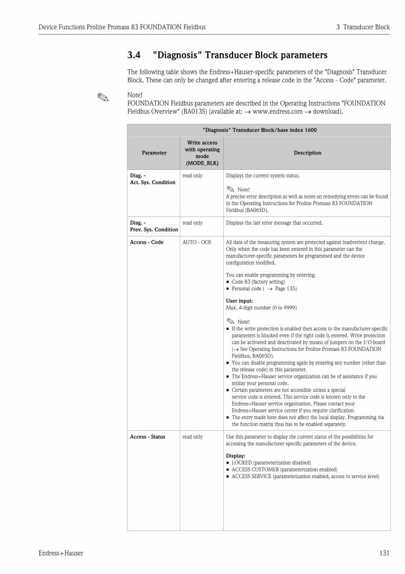
Device Functions Proline Promass 83 FOUNDATION Fieldbus 3 Transducer Block
Endress+Hauser 131
3.4 "Diagnosis" Transducer Block parameters
The following table shows the Endress+Hauser-specific parameters of the "Diagnosis" Transducer
Block. These can only be changed after entering a release code in the "Access - Code" parameter.
! Note!
FOUNDATION Fieldbus parameters are described in the Operating Instructions "FOUNDATION
Fieldbus Overview" (BA013S) (available at: → www.endress.com → download).
"Diagnosis" Transducer Block/base index 1600
Parameter
Write access
with operating
mode
(MODE_BLK)
Description
Diag. -
Act. Sys. Condition
read only Displays the current system status.
! Note!
A precise error description as well as notes on remedying errors can be found
in the Operating Instructions for Proline Promass 83 FOUNDATION
Fieldbus (BA065D).
Diag. -
Prev. Sys. Condition
read only Displays the last error message that occurred.
Access - Code AUTO - OOS All data of the measuring system are protected against inadvertent change.
Only when the code has been entered in this parameter can the
manufacturer-specific parameters be programmed and the device
configuration modified.
You can enable programming by entering:
• Code 83 (factory setting)
• Personal code ( → Page 135)
User input:
Max. 4-digit number (0 to 9999)
! Note!
• If the write protection is enabled then access to the manufacturer-specific
parameters is blocked even if the right code is entered. Write protection
can be activated and deactivated by means of jumpers on the I/O board
(→ See Operating Instructions for Proline Promass 83 FOUNDATION
Fieldbus, BA065D).
• You can disable programming again by entering any number (other than
the release code) in this parameter.
• The Endress+Hauser service organization can be of assistance if you
mislay your personal code.
• Certain parameters are not accessible unless a special
service code is entered. This service code is known only to the
Endress+Hauser service organization. Please contact your
Endress+Hauser service center if you require clarification.
• The entry made here does not affect the local display. Programming via
the function matrix thus has to be enabled separately.
Access - Status read only Use this parameter to display the current status of the possibilities for
accessing the manufacturer-specific parameters of the device.
Display:
• LOCKED (parameterization disabled)
• ACCESS CUSTOMER (parameterization enabled)
• ACCESS SERVICE (parameterization enabled, access to service level)

3 Transducer Block Device Functions Proline Promass 83 FOUNDATION Fieldbus
132 Endress+Hauser
Sys. - Alarm Delay AUTO - OOS Use this function to define a time span for which the criteria for an error
have to be satisfied without interruption before a fault or notice message is
generated.
Depending on the setting and the type of error, this suppression acts on:
• Display
• Output Blocks (AI Blocks), FOUNDATION Fieldbus interface
User input:
0 to 100 s (in steps of one second)
Factory setting:
0 s
" Caution!
If this parameter is used, fault and notice messages are delayed by the time
corresponding to the setting before being forwarded to the downstream
function blocks or the fieldbus host system.
It is therefore imperative to check in advance in order to make sure whether
a delay of this nature could affect the safety requirements of the process. If
fault and notice messages may not be suppressed, a value of 0 seconds must
be entered here.
Sys. -
Sim. Failsafe Mode
AUTO - OOS Use this parameter to set the Analog Input and Totalizer function blocks
to their defined failsafe modes, in order to check whether they respond
correctly. The failsafe mode of the totalizers is defined via the
"Tot. - Failsafe All" parameter ( → Page 154).
Options:
OFF
ON
Factory setting:
OFF
! Note!
Active simulation mode is relayed to downstream function blocks or higher-
level process control systems by means of the status "UNCERTAIN" of the
output value OUT (AI Block).
Sys. - Reset AUTO - OOS Use this parameter to perform a reset of the measuring system.
Options:
NO
RESTART SYSTEM (restart without interrupting power supply)
ORIGINAL TRANSMITTER DATA
Factory setting:
NO
Sys. -
Operation Time
read only The total operating time since the flowmeter was commissioned appears on
the display (in seconds).
Sys. -
Time Since Reset
read only This parameter is only used for service purposes.
"Diagnosis" Transducer Block/base index 1600
Parameter
Write access
with operating
mode
(MODE_BLK)
Description

Device Functions Proline Promass 83 FOUNDATION Fieldbus 3 Transducer Block
Endress+Hauser 133
Sys. -
T-DAT Save/Load
AUTO - OOS Use this parameter to save the parameter settings / configuration of the
transmitter in a transmitter DAT (T-DAT), or to load the parameter settings
from the T-DAT into the EEPROM (manual backup function).
Application examples:
• After commissioning, the current measuring point parameters can be
saved to the T-DAT as a backup.
• If the transmitter is replaced for some reason, the data from the T-DAT
can be loaded into the new transmitter (EEPROM).
Options:
CANCEL
SAVE (from EEPROM to T-DAT)
LOAD (from the T-DAT into EEPROM)
Factory setting:
CANCEL
! Note!
• If the target device has an older software version, the message
"TRANSM. SW–DAT" is displayed during startup. Then only the SAVE
option is available.
• LOAD
This option is only possible:
– If the target device has the same software version as, or a more recent
software version than, the source device or
– If the T-DAT contains valid data that can be called up.
• SAVE This option is always available.
Amp. Device Type read only This parameter is only used for service purposes.
"Diagnosis" Transducer Block/base index 1600
Parameter
Write access
with operating
mode
(MODE_BLK)
Description

3 Transducer Block Device Functions Proline Promass 83 FOUNDATION Fieldbus
134 Endress+Hauser
3.5 "Display" Transducer Block parameters
The following table shows the Endress+Hauser-specific parameters of the "Display" Transducer
Block. These can only be changed after entering a release code in the "Access - Code" parameter.
! Note!
FOUNDATION Fieldbus parameters are described in the Operating Instructions "FOUNDATION
Fieldbus Overview" (BA013S) (available at: → www.endress.com → download).
"Display" Transducer Block/base index 1800
Parameter
Write access
with operating
mode
(MODE_BLK)
Description
Access - Code AUTO - OOS All data of the measuring system are protected against inadvertent change.
Only when the code has been entered in this parameter can the
manufacturer-specific parameters be programmed and the device
configuration modified.
You can enable programming by entering:
• Code 83 (factory setting)
• Personal code ( → Page 135)
User input:
Max. 4-digit number (0 to 9999)
! Note!
• If the write protection is enabled then access to the manufacturer-specific
parameters is blocked even if the right code is entered. Write protection
can be activated and deactivated by means of jumpers on the I/O board
(→ See Operating Instructions for Proline Promass 83 FOUNDATION
Fieldbus).
• You can disable programming again by entering any number (other than
the release code) in this parameter.
• The Endress+Hauser service organization can be of assistance if you
mislay your personal code.
• Certain parameters are not accessible unless a special
service code is entered. This service code is known only to the
Endress+Hauser service organization. Please contact your
Endress+Hauser service center if you require clarification.
• The entry made here does not affect the local display. Programming via
the function matrix thus has to be enabled separately.
Access - Status read only Use this parameter to display the current status of the possibilities for
accessing the manufacturer-specific parameters of the device.
Display:
• LOCKED (parameterization disabled)
• ACCESS CUSTOMER (parameterization enabled)
• ACCESS SERVICE (parameterization enabled, access to service level)
Access - Code
Counter
read only Displays how often the customer code, service code or the digit "0"
(code-free) has been entered to gain access to the measuring device.
Display:
Max. 7-digit number: 0 to 9999999
Factory setting:
0

Device Functions Proline Promass 83 FOUNDATION Fieldbus 3 Transducer Block
Endress+Hauser 135
Access -
Def.Private Code
AUTO - OOS Use this function to enter a personal code to enable configuration. This
applies both to manufacturer-specific parameters in the Transducer Blocks
and to operating via the local display.
User input:
0 to 9999 (max. 4-digit number)
Factory setting:
83
! Note!
• If the code number is "0", programming is always enabled.
• Parameter configuration has to be enabled before this code can be
changed.
Config. - Language AUTO - OOS Use this parameter to select the language for all texts, parameters and
messages shown on the local display.
! Note!
The displayed options depend on the language group available which is
shown in the "Amp. - Language Group" parameter.
Options:
Language group WEST EU / USA:
ENGLISH
DEUTSCH
FRANCAIS
ESPANOL
ITALIANO
NEDERLANDS
PORTUGUESE
Language group EAST EU / SCAND:
ENGLISH
NORSK
SVENSKA
SUOMI
POLISH
RUSSIAN
CZECH
Language group ASIA:
ENGLISH
BAHASA INDONESIA
JAPANESE (syllabary)
Language group CHINA:
ENGLISH
CHINESE
Factory setting:
Depends on country → Page 193 ff.
! Note!
You can change the language group via the configuration software
ToF Tool-Fieldtool Package. Please do not hesitate to contact your
Endress+Hauser sales office if you have any questions.
"Display" Transducer Block/base index 1800
Parameter
Write access
with operating
mode
(MODE_BLK)
Description
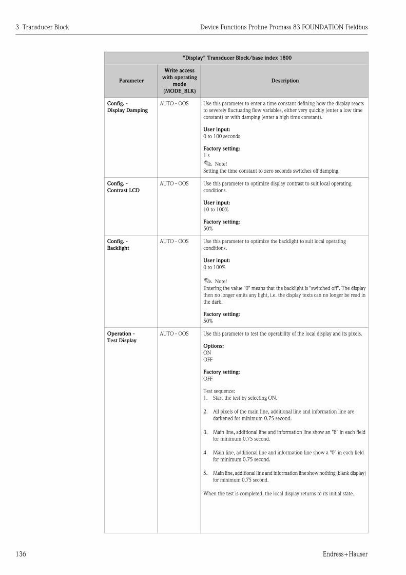
3 Transducer Block Device Functions Proline Promass 83 FOUNDATION Fieldbus
136 Endress+Hauser
Config. -
Display Damping
AUTO - OOS Use this parameter to enter a time constant defining how the display reacts
to severely fluctuating flow variables, either very quickly (enter a low time
constant) or with damping (enter a high time constant).
User input:
0 to 100 seconds
Factory setting:
1 s
! Note!
Setting the time constant to zero seconds switches off damping.
Config. -
Contrast LCD
AUTO - OOS Use this parameter to optimize display contrast to suit local operating
conditions.
User input:
10 to 100%
Factory setting:
50%
Config. -
Backlight
AUTO - OOS Use this parameter to optimize the backlight to suit local operating
conditions.
User input:
0 to 100%
! Note!
Entering the value "0" means that the backlight is "switched off". The display
then no longer emits any light, i.e. the display texts can no longer be read in
the dark.
Factory setting:
50%
Operation -
Test Display
AUTO - OOS Use this parameter to test the operability of the local display and its pixels.
Options:
ON
OFF
Factory setting:
OFF
Test sequence:
1. Start the test by selecting ON.
2. All pixels of the main line, additional line and information line are
darkened for minimum 0.75 second.
3. Main line, additional line and information line show an "8" in each field
for minimum 0.75 second.
4. Main line, additional line and information line show a "0" in each field
for minimum 0.75 second.
5. Main line, additional line and information line show nothing (blank display)
for minimum 0.75 second.
When the test is completed, the local display returns to its initial state.
"Display" Transducer Block/base index 1800
Parameter
Write access
with operating
mode
(MODE_BLK)
Description

Device Functions Proline Promass 83 FOUNDATION Fieldbus 3 Transducer Block
Endress+Hauser 137
1 = Main line
2 = Additional line
3 = Info line
A0001253
Main Line -
Assign
AUTO - OOS In this parameter, a value to be displayed is assigned to the main line (top
line in the local display). This value is displayed during normal operation.
Options (standard):
OFF
MASS FLOW
MASS FLOW IN %
VOLUME FLOW
VOLUME FLOW IN %
CORRECTED VOLUME FLOW
CORRECTED VOLUME FLOW IN %
DENSITY
REFERENCE DENSITY
TEMPERATURE
TOTALIZER (1 to 3)
AI (1 to 8) - OUT VALUE
PID - IN VALUE (controlled variable)
PID - CAS IN VALUE (external set point)
PID - OUT VALUE (manipulated variable)
Factory setting:
MASS FLOW
Advanced options with optional software package
CONCENTRATION:
TARGET MASS FLOW
% TARGET MASS FLOW
TARGET VOLUME FLOW
% TARGET VOLUME FLOW
CORRECTED TARGET VOLUME FLOW
CARRIER MASS FLOW
% CARRIER MASS FLOW
CARRIER VOLUME FLOW
% CARRIER VOLUME FLOW
CORRECTED CARRIER VOLUME FLOW
% BLACK LIQUOR
° BAUME
° API
° PLATO
° BALLING
° BRIX
(Continued on next page)
"Display" Transducer Block/base index 1800
Parameter
Write access
with operating
mode
(MODE_BLK)
Description
Esc
E+-
1
2
3

3 Transducer Block Device Functions Proline Promass 83 FOUNDATION Fieldbus
138 Endress+Hauser
Main Line -
Assign
(continued)
Advanced options with optional software package
ADVANCED DIAGNOSTICS:
MASS FLOW DEVIATION
DENSITY DEVIATION
REFERENCE DENSITY DEVIATION
TEMPERATURE DEVIATION
TUBE DAMPING DEVIATION
ELECTRODYNAMIC SENSOR DEVIATION
OPERATING FREQUENCY FLUCTUATION DEVIATION
TUBE DAMPING FLUCTUATION DEVIATION
Main Line -
100%-Value
AUTO - OOS The entry is not active unless one of the following was selected in the
parameter "Main Line - Assign":
• MASS FLOW IN %
• VOLUME FLOW IN %
• CORRECTED VOLUME FLOW IN %
Use this parameter to define the flow value to be shown on the display as the
100% value.
User input:
5-digit floating-point number
Factory setting:
Depends on nominal diameter and country → Page 193 ff.
! Note!
The appropriate unit is taken from the corresponding parameter
("System Unit - Mass Flow", "System Unit - Volume Flow", or
"System Unit - Corrected Volume Flow"). ( → Page 114 ff.).
Main Line -
Format
AUTO - OOS Use this parameter to define the maximum number of places after the
decimal point displayed for the reading in the main line.
Options:
XXXXX. - XXXX.X - XXX.XX - XX.XXX -X.XXXX
Factory setting:
X.XXXX
! Note!
• Note that this setting only affects the reading as it appears on the display,
it has no influence on the accuracy of the system's calculations.
• The places after the decimal point as computed by the measuring device
cannot always be displayed, depending on this setting and the engineering
unit. In these instances an arrow appears on the display between the
measured value and the engineering unit (e.g. 1.2 → kg/h), indicating
that the measuring system is computing with more decimal places than
can be shown on the display.
"Display" Transducer Block/base index 1800
Parameter
Write access
with operating
mode
(MODE_BLK)
Description

Device Functions Proline Promass 83 FOUNDATION Fieldbus 3 Transducer Block
Endress+Hauser 139
Main Line Mux -
Assign
AUTO - OOS Use this parameter to define the second reading to be displayed in the main
line alternately (every 10 seconds) with the value defined in the parameter
"Main - Line Assign".
Options (standard):
OFF
MASS FLOW
MASS FLOW IN %
VOLUME FLOW
VOLUME FLOW IN %
CORRECTED VOLUME FLOW
CORRECTED VOLUME FLOW IN %
DENSITY
REFERENCE DENSITY
TEMPERATURE
TOTALIZER (1 to 3)
AI (1 to 8) - OUT VALUE
PID - IN VALUE (controlled variable)
PID - CAS IN VALUE (external set point)
PID - OUT VALUE (manipulated variable)
Factory setting:
OFF
Advanced options with optional software package
CONCENTRATION:
TARGET MASS FLOW
% TARGET MASS FLOW
TARGET VOLUME FLOW
% TARGET VOLUME FLOW
CORRECTED TARGET VOLUME FLOW
CARRIER MASS FLOW
% CARRIER MASS FLOW
CARRIER VOLUME FLOW
% CARRIER VOLUME FLOW
CORRECTED CARRIER VOLUME FLOW
% BLACK LIQUOR
° BAUME
° API
° PLATO
° BALLING
° BRIX
Advanced options with optional software package
ADVANCED DIAGNOSTICS:
MASS FLOW DEVIATION
DENSITY DEVIATION
REFERENCE DENSITY DEVIATION
TEMPERATURE DEVIATION
TUBE DAMPING DEVIATION
ELECTRODYNAMIC SENSOR DEVIATION
OPERATING FREQUENCY FLUCTUATION DEVIATION
TUBE DAMPING FLUCTUATION DEVIATION
"Display" Transducer Block/base index 1800
Parameter
Write access
with operating
mode
(MODE_BLK)
Description

3 Transducer Block Device Functions Proline Promass 83 FOUNDATION Fieldbus
140 Endress+Hauser
Main Line Mux -
100%-Value
AUTO - OOS! Note!
The entry is not active unless one of the following was selected in the
parameter "Main Line Mux - Assign":
• MASS FLOW IN %
• VOLUME FLOW IN %
• CORRECTED VOLUME FLOW IN %
Use this parameter to define the flow value to be shown on the display as the
100% value.
User input:
5-digit floating-point number
Factory setting:
Depends on nominal diameter and country → Page 193 ff.
! Note!
The appropriate unit is taken from the corresponding parameter
("System Unit - Mass Flow", "System Unit - Volume Flow", or
"System Unit - Corrected Volume Flow"). ( → Page 114 ff.).
Main Line Mux -
Format
AUTO - OOS Use this parameter to define the maximum number of places after the
decimal point displayed for the reading in the main line.
Options:
XXXXX. - XXXX.X - XXX.XX - XX.XXX -X.XXXX
Factory setting:
X.XXXX
! Note!
• Note that this setting only affects the reading as it appears on the display,
it has no influence on the accuracy of the system's calculations.
• The places after the decimal point as computed by the measuring device
cannot always be displayed, depending on this setting and the engineering
unit. In these instances an arrow appears on the display between the
measured value and the engineering unit (e.g. 1.2 → kg/h), indicating
that the measuring system is computing with more decimal places than
can be shown on the display.
"Display" Transducer Block/base index 1800
Parameter
Write access
with operating
mode
(MODE_BLK)
Description

Device Functions Proline Promass 83 FOUNDATION Fieldbus 3 Transducer Block
Endress+Hauser 141
1 = Main line
2 = Additional line
3 = Info line
A0001253
Add. Line -
Assign
AUTO - OOS Use this parameter to define the display value assigned to the additional line
(the middle line of the local display) during normal measuring operation.
Options (standard):
OFF
MASS FLOW
MASS FLOW IN %
VOLUME FLOW
VOLUME FLOW IN %
CORRECTED VOLUME FLOW
CORRECTED VOLUME FLOW IN %
DENSITY
REFERENCE DENSITY
TEMPERATURE
TOTALIZER (1 to 3)
MASS FLOW BAR GRAPH IN %
VOLUME FLOW BAR GRAPH IN %
CORRECTED VOLUME FLOW BAR GRAPH IN %
AI (1 to 8) - OUT VALUE
PID - IN VALUE (controlled variable)
PID - CAS IN VALUE (external set point)
PID - OUT VALUE (manipulated variable)
DEVICE PD-TAG
Factory setting:
TOTALIZER 1
Advanced options with optional software package
CONCENTRATION:
TARGET MASS FLOW
% TARGET MASS FLOW
TARGET VOLUME FLOW
% TARGET VOLUME FLOW
CORRECTED TARGET VOLUME FLOW
CARRIER MASS FLOW
% CARRIER MASS FLOW
CARRIER VOLUME FLOW
% CARRIER VOLUME FLOW
CORRECTED CARRIER VOLUME FLOW
% BLACK LIQUOR
° BAUME
° API
° PLATO
° BALLING
° BRIX
(Continued on next page)
"Display" Transducer Block/base index 1800
Parameter
Write access
with operating
mode
(MODE_BLK)
Description
Esc
E+-
1
2
3

3 Transducer Block Device Functions Proline Promass 83 FOUNDATION Fieldbus
142 Endress+Hauser
Add. Line -
Assign
(continued)
Advanced options with optional software package
ADVANCED DIAGNOSTICS:
MASS FLOW DEVIATION
DENSITY DEVIATION
REFERENCE DENSITY DEVIATION
TEMPERATURE DEVIATION
TUBE DAMPING DEVIATION
ELECTRODYNAMIC SENSOR DEVIATION
OPERATING FREQUENCY FLUCTUATION DEVIATION
TUBE DAMPING FLUCTUATION DEVIATION
Add. Line -
100%-Value
AUTO - OOS! Note!
The entry is not active unless one of the following was selected in the
parameter "Add. Line - Assign":
• MASS FLOW IN %
• VOLUME FLOW IN %
• CORRECTED VOLUME FLOW IN %
• MASS FLOW BAR GRAPH IN %
• VOLUME FLOW BAR GRAPH IN %
• CORRECTED VOLUME FLOW BAR GRAPH IN %
Use this parameter to define the flow value to be shown on the display as the
100% value.
User input:
5-digit floating-point number
Factory setting:
Depends on nominal diameter and country → Page 193 ff.
! Note!
The appropriate unit is taken from the corresponding parameter
("System Unit - Mass Flow", "System Unit - Volume Flow", or
"System Unit - Corrected Volume Flow"). ( → Page 114 ff.).
Add. Line -
Format
AUTO - OOS! Note!
The option is not active unless a number was selected in the
parameter "Add. Line - Assign".
Use this parameter to define the maximum number of places after the
decimal point displayed for the reading in the additional line.
Options:
XXXXX. - XXXX.X - XXX.XX - XX.XXX -X.XXXX
Factory setting:
X.XXXX
! Note!
• Note that this setting only affects the reading as it appears on the display,
it has no influence on the accuracy of the system's calculations.
• The places after the decimal point as computed by the measuring device
cannot always be displayed, depending on this setting and the engineering
unit. In these instances an arrow appears on the display between the
measured value and the engineering unit (e.g. 1.2 → kg/h), indicating
that the measuring system is computing with more decimal places than
can be shown on the display.
"Display" Transducer Block/base index 1800
Parameter
Write access
with operating
mode
(MODE_BLK)
Description

Device Functions Proline Promass 83 FOUNDATION Fieldbus 3 Transducer Block
Endress+Hauser 143
Add. Line -
Display Mode
AUTO - OOS! Note!
The option is not active unless one of the following was selected in the
parameter "Add. Line - Assign":
• MASS FLOW BAR GRAPH IN %
• VOLUME FLOW BAR GRAPH IN %
• CORRECTED VOLUME FLOW BAR GRAPH IN %
Use this parameter to define the format of the bar graph.
Options:
STANDARD (Simple bar graph with 25 / 50 / 75% gradations and
integrated sign).
A0001258
SYMMETRY (Symmetrical bar graph for positive and negative directions of
flow, with –50 / 0 / +50% gradations and integrated sign).
A0001259
Factory setting:
STANDARD
Add. Line Mux -
Assign
AUTO - OOS Use this parameter to define the second reading to be displayed in the
additional line alternately (every 10 seconds) with the value defined in the
parameter "Add. Line - Assign" ( → Page 141).
Options (standard):
OFF
MASS FLOW
MASS FLOW IN %
VOLUME FLOW
VOLUME FLOW IN %
CORRECTED VOLUME FLOW
CORRECTED VOLUME FLOW IN %
DENSITY
REFERENCE DENSITY
TEMPERATURE
TOTALIZER (1 to 3)
MASS FLOW BAR GRAPH IN %
VOLUME FLOW BAR GRAPH IN %
CORRECTED VOLUME FLOW BAR GRAPH IN %
AI (1 to 8) - OUT VALUE
PID - IN VALUE (controlled variable)
PID - CAS IN VALUE (external set point)
PID - OUT VALUE (manipulated variable)
DEVICE PD-TAG
Factory setting:
OFF
(Continued on next page)
"Display" Transducer Block/base index 1800
Parameter
Write access
with operating
mode
(MODE_BLK)
Description

3 Transducer Block Device Functions Proline Promass 83 FOUNDATION Fieldbus
144 Endress+Hauser
Add. Line Mux -
Assign
(continued)
Advanced options with optional software package
CONCENTRATION:
TARGET MASS FLOW
% TARGET MASS FLOW
TARGET VOLUME FLOW
% TARGET VOLUME FLOW
CORRECTED TARGET VOLUME FLOW
CARRIER MASS FLOW
% CARRIER MASS FLOW
CARRIER VOLUME FLOW
% CARRIER VOLUME FLOW
CORRECTED CARRIER VOLUME FLOW
% BLACK LIQUOR
° BAUME
° API
° PLATO
° BALLING
° BRIX
Advanced options with optional software package
ADVANCED DIAGNOSTICS:
MASS FLOW DEVIATION
DENSITY DEVIATION
REFERENCE DENSITY DEVIATION
TEMPERATURE DEVIATION
TUBE DAMPING DEVIATION
ELECTRODYNAMIC SENSOR DEVIATION
OPERATING FREQUENCY FLUCTUATION DEVIATION
TUBE DAMPING FLUCTUATION DEVIATION
! Note!
Multiplex mode is suspended as soon as a fault or notice message is
generated. The corresponding error message appears in the parameter
"Diag. - Act.Sys.Condition" ( → Page 131). The measuring device resumes
Multiplex operation when the fault is rectified.
Add. Line Mux -
100%-Value
AUTO - OOS! Note!
The entry is not active unless one of the following was selected in the
parameter "Add. Line Mux - Assign":
• MASS FLOW IN %
• VOLUME FLOW IN %
• CORRECTED VOLUME FLOW IN %
• MASS FLOW BAR GRAPH IN %
• VOLUME FLOW BAR GRAPH IN %
• CORRECTED VOLUME FLOW BAR GRAPH IN %
Use this parameter to define the flow value to be shown on the display as the
100% value.
User input:
5-digit floating-point number
Factory setting:
Depends on nominal diameter and country → Page 193 ff.
! Note!
The appropriate unit is taken from the corresponding parameter
("System Unit - Mass Flow", "System Unit - Volume Flow", or
"System Unit - Corrected Volume Flow"). ( → Page 114 ff.).
"Display" Transducer Block/base index 1800
Parameter
Write access
with operating
mode
(MODE_BLK)
Description

Device Functions Proline Promass 83 FOUNDATION Fieldbus 3 Transducer Block
Endress+Hauser 145
Add. Line Mux -
Format
AUTO - OOS! Note!
The option is not active unless a number was selected in the
parameter "Add. Line Mux - Assign" ( → Page 143).
Use this parameter to define the maximum number of places after the
decimal point displayed for the reading in the additional line.
Options:
XXXXX. - XXXX.X - XXX.XX - XX.XXX -X.XXXX
Factory setting:
X.XXXX
! Note!
• Note that this setting only affects the reading as it appears on the display,
it has no influence on the accuracy of the system's calculations.
• The places after the decimal point as computed by the measuring device
cannot always be displayed, depending on this setting and the engineering
unit. In these instances an arrow appears on the display between the
measured value and the engineering unit (e.g. 1.2 → kg/h), indicating
that the measuring system is computing with more decimal places than
can be shown on the display.
Add. Line Mux -
Display Mode
AUTO - OOS! Note!
The option is not active unless one of the following was selected in the
parameter "Add. Line Mux - Assign" ( → Page 143).
• MASS FLOW BAR GRAPH IN %
• VOLUME FLOW BAR GRAPH IN %
• CORRECTED VOLUME FLOW BAR GRAPH IN %
Use this parameter to define the format of the bar graph.
Options:
STANDARD (Simple bar graph with 25 / 50 / 75% gradations and
integrated sign).
A0001258
SYMMETRY (Symmetrical bar graph for positive and negative directions of
flow, with –50 / 0 / +50% gradations and integrated sign).
A0001259
Factory setting:
STANDARD
"Display" Transducer Block/base index 1800
Parameter
Write access
with operating
mode
(MODE_BLK)
Description

3 Transducer Block Device Functions Proline Promass 83 FOUNDATION Fieldbus
146 Endress+Hauser
1 = Main line
2 = Additional line
3 = Info line
A0001253
Info Line -
Assign
AUTO - OOS Use this parameter to define the display value assigned to the information
line (the bottom line of the local display) during normal measuring
operation.
Options (standard):
OFF
MASS FLOW
MASS FLOW IN %
VOLUME FLOW
VOLUME FLOW IN %
CORRECTED VOLUME FLOW
CORRECTED VOLUME FLOW IN %
DENSITY
REFERENCE DENSITY
TEMPERATURE
TOTALIZER (1 to 3)
MASS FLOW BAR GRAPH IN %
VOLUME FLOW BAR GRAPH IN %
CORRECTED VOLUME FLOW BAR GRAPH IN %
OPERATION SYSTEM CONDITION
DISPLAY FLOW DIRECTION
AI (1 to 8) - OUT VALUE
PID - IN VALUE (controlled variable)
PID - CAS IN VALUE (external set point)
PID - OUT VALUE (manipulated variable)
DEVICE PD-TAG
Factory setting:
OPERATION SYSTEM CONDITION
Advanced options with optional software package
CONCENTRATION:
TARGET MASS FLOW
% TARGET MASS FLOW
TARGET VOLUME FLOW
% TARGET VOLUME FLOW
CORRECTED TARGET VOLUME FLOW
CARRIER MASS FLOW
% CARRIER MASS FLOW
CARRIER VOLUME FLOW
% CARRIER VOLUME FLOW
CORRECTED CARRIER VOLUME FLOW
% BLACK LIQUOR
° BAUME
° API
° PLATO
° BALLING
° BRIX
(Continued on next page)
"Display" Transducer Block/base index 1800
Parameter
Write access
with operating
mode
(MODE_BLK)
Description
Esc
E+-
1
2
3

Device Functions Proline Promass 83 FOUNDATION Fieldbus 3 Transducer Block
Endress+Hauser 147
Info Line -
Assign
(continued)
Advanced options with optional software package
ADVANCED DIAGNOSTICS:
MASS FLOW DEVIATION
DENSITY DEVIATION
REFERENCE DENSITY DEVIATION
TEMPERATURE DEVIATION
TUBE DAMPING DEVIATION
ELECTRODYNAMIC SENSOR DEVIATION
OPERATING FREQUENCY FLUCTUATION DEVIATION
TUBE DAMPING FLUCTUATION DEVIATION
! Note!
Multiplex mode is suspended as soon as a fault or notice message is
generated. The corresponding error message appears in the parameter
"Diag. - Act.Sys.Condition" ( → Page 131). The measuring device resumes
Multiplex operation when the fault is rectified.
Info Line -
100%-Value
AUTO - OOS! Note!
The entry is not active unless one of the following was selected in the
parameter "Info Line - Assign" ( → Page 146):
• MASS FLOW IN %
• VOLUME FLOW IN %
• CORRECTED VOLUME FLOW IN %
• MASS FLOW BAR GRAPH IN %
• VOLUME FLOW BAR GRAPH IN %
• CORRECTED VOLUME FLOW BAR GRAPH IN %
Use this parameter to define the flow value to be shown on the display as the
100% value.
User input:
5-digit floating-point number
Factory setting:
Depends on nominal diameter and country → Page 193 ff.
! Note!
The appropriate unit is taken from the corresponding parameter
("System Unit - Mass Flow", "System Unit - Volume Flow", or
"System Unit - Corrected Volume Flow"). ( → Page 114 ff.).
Info Line -
Format
AUTO - OOS! Note!
The option is not active unless a number was selected in the parameter "Info
Line - Assign" ( → Page 146).
Use this parameter to define the maximum number of places after the
decimal point displayed for the reading in the additional line.
Options:
XXXXX. - XXXX.X - XXX.XX - XX.XXX -X.XXXX
Factory setting:
X.XXXX
! Note!
• Note that this setting only affects the reading as it appears on the display,
it has no influence on the accuracy of the system's calculations.
• The places after the decimal point as computed by the measuring device
cannot always be displayed, depending on this setting and the engineering
unit. In these instances an arrow appears on the display between the
measured value and the engineering unit (e.g. 1.2 → kg/h), indicating
that the measuring system is computing with more decimal places than
can be shown on the display.
"Display" Transducer Block/base index 1800
Parameter
Write access
with operating
mode
(MODE_BLK)
Description

3 Transducer Block Device Functions Proline Promass 83 FOUNDATION Fieldbus
148 Endress+Hauser
Info Line -
Display Mode
AUTO - OOS! Note!
The option is not active unless one of the following was selected in the
parameter "Info Line - Assign" ( → Page 146):
• MASS FLOW BAR GRAPH IN %
• VOLUME FLOW BAR GRAPH IN %
• CORRECTED VOLUME FLOW BAR GRAPH IN %
Use this parameter to define the format of the bar graph.
Options:
STANDARD (Simple bar graph with 25 / 50 / 75% gradations and
integrated sign).
A0001258
SYMMETRY (Symmetrical bar graph for positive and negative directions of
flow, with –50 / 0 / +50% gradations and integrated sign).
A0001259
Factory setting:
STANDARD
Info Line Mux -
Assign
AUTO - OOS Use this parameter to define the second reading to be displayed in the
information line alternately (every 10 seconds) with the value defined in the
parameter "Info Line - Assign" ( → Page 146).
Options (standard):
OFF
MASS FLOW
MASS FLOW IN %
VOLUME FLOW
VOLUME FLOW IN %
CORRECTED VOLUME FLOW
CORRECTED VOLUME FLOW IN %
DENSITY
REFERENCE DENSITY
TEMPERATURE
TOTALIZER (1 to 3)
MASS FLOW BAR GRAPH IN %
VOLUME FLOW BAR GRAPH IN %
CORRECTED VOLUME FLOW BAR GRAPH IN %
OPERATION SYSTEM CONDITION
DISPLAY FLOW DIRECTION
AI (1 to 8) - OUT VALUE
PID - IN VALUE (controlled variable)
PID - CAS IN VALUE (external set point)
PID - OUT VALUE (manipulated variable)
DEVICE PD-TAG
Factory setting:
OFF
(Continued on next page)
"Display" Transducer Block/base index 1800
Parameter
Write access
with operating
mode
(MODE_BLK)
Description
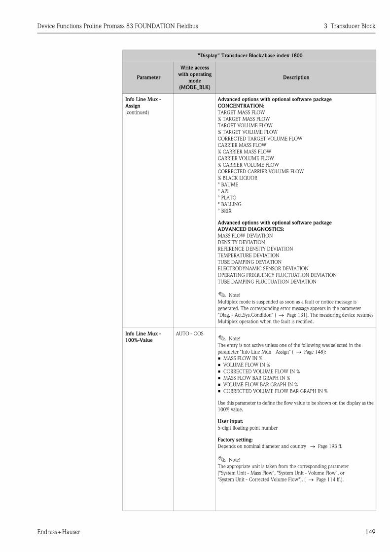
Device Functions Proline Promass 83 FOUNDATION Fieldbus 3 Transducer Block
Endress+Hauser 149
Info Line Mux -
Assign
(continued)
Advanced options with optional software package
CONCENTRATION:
TARGET MASS FLOW
% TARGET MASS FLOW
TARGET VOLUME FLOW
% TARGET VOLUME FLOW
CORRECTED TARGET VOLUME FLOW
CARRIER MASS FLOW
% CARRIER MASS FLOW
CARRIER VOLUME FLOW
% CARRIER VOLUME FLOW
CORRECTED CARRIER VOLUME FLOW
% BLACK LIQUOR
° BAUME
° API
° PLATO
° BALLING
° BRIX
Advanced options with optional software package
ADVANCED DIAGNOSTICS:
MASS FLOW DEVIATION
DENSITY DEVIATION
REFERENCE DENSITY DEVIATION
TEMPERATURE DEVIATION
TUBE DAMPING DEVIATION
ELECTRODYNAMIC SENSOR DEVIATION
OPERATING FREQUENCY FLUCTUATION DEVIATION
TUBE DAMPING FLUCTUATION DEVIATION
! Note!
Multiplex mode is suspended as soon as a fault or notice message is
generated. The corresponding error message appears in the parameter
"Diag. - Act.Sys.Condition" ( → Page 131). The measuring device resumes
Multiplex operation when the fault is rectified.
Info Line Mux -
100%-Value
AUTO - OOS! Note!
The entry is not active unless one of the following was selected in the
parameter "Info Line Mux - Assign" ( → Page 148):
• MASS FLOW IN %
• VOLUME FLOW IN %
• CORRECTED VOLUME FLOW IN %
• MASS FLOW BAR GRAPH IN %
• VOLUME FLOW BAR GRAPH IN %
• CORRECTED VOLUME FLOW BAR GRAPH IN %
Use this parameter to define the flow value to be shown on the display as the
100% value.
User input:
5-digit floating-point number
Factory setting:
Depends on nominal diameter and country → Page 193 ff.
! Note!
The appropriate unit is taken from the corresponding parameter
("System Unit - Mass Flow", "System Unit - Volume Flow", or
"System Unit - Corrected Volume Flow"). ( → Page 114 ff.).
"Display" Transducer Block/base index 1800
Parameter
Write access
with operating
mode
(MODE_BLK)
Description
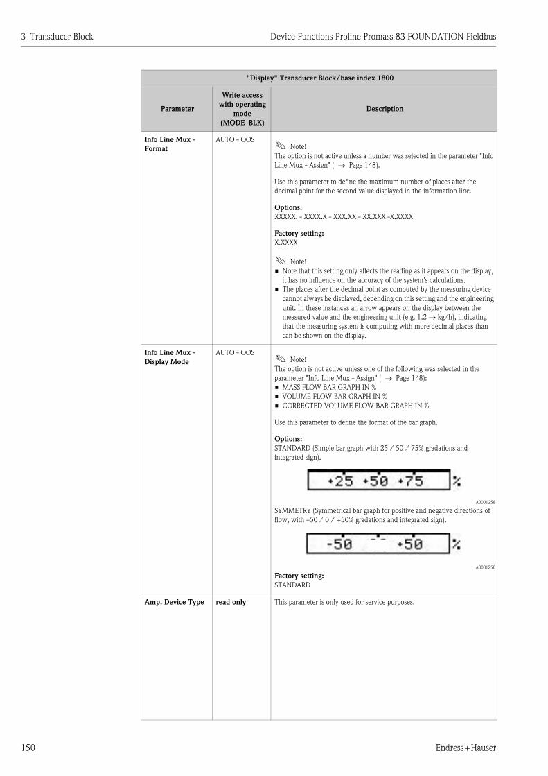
3 Transducer Block Device Functions Proline Promass 83 FOUNDATION Fieldbus
150 Endress+Hauser
Info Line Mux -
Format
AUTO - OOS! Note!
The option is not active unless a number was selected in the parameter "Info
Line Mux - Assign" ( → Page 148).
Use this parameter to define the maximum number of places after the
decimal point for the second value displayed in the information line.
Options:
XXXXX. - XXXX.X - XXX.XX - XX.XXX -X.XXXX
Factory setting:
X.XXXX
! Note!
• Note that this setting only affects the reading as it appears on the display,
it has no influence on the accuracy of the system's calculations.
• The places after the decimal point as computed by the measuring device
cannot always be displayed, depending on this setting and the engineering
unit. In these instances an arrow appears on the display between the
measured value and the engineering unit (e.g. 1.2 → kg/h), indicating
that the measuring system is computing with more decimal places than
can be shown on the display.
Info Line Mux -
Display Mode
AUTO - OOS! Note!
The option is not active unless one of the following was selected in the
parameter "Info Line Mux - Assign" ( → Page 148):
• MASS FLOW BAR GRAPH IN %
• VOLUME FLOW BAR GRAPH IN %
• CORRECTED VOLUME FLOW BAR GRAPH IN %
Use this parameter to define the format of the bar graph.
Options:
STANDARD (Simple bar graph with 25 / 50 / 75% gradations and
integrated sign).
A0001258
SYMMETRY (Symmetrical bar graph for positive and negative directions of
flow, with –50 / 0 / +50% gradations and integrated sign).
A0001258
Factory setting:
STANDARD
Amp. Device Type read only This parameter is only used for service purposes.
"Display" Transducer Block/base index 1800
Parameter
Write access
with operating
mode
(MODE_BLK)
Description

Device Functions Proline Promass 83 FOUNDATION Fieldbus 3 Transducer Block
Endress+Hauser 151
3.6 "Totalizer" Transducer Block parameters
The following table shows the Endress+Hauser-specific parameters of the "Totalizer" Transducer
Block. These can only be changed after entering a release code in the "Access - Code" parameter.
! Note!
FOUNDATION Fieldbus parameters are described in the Operating Instructions "FOUNDATION
Fieldbus Overview" (BA013S) (available at: → www.endress.com → download).
"Totalizer" Transducer Block/base index 1900
Parameter
Write access
with operating
mode
(MODE_BLK)
Description
Access - Code AUTO - OOS All data of the measuring system are protected against inadvertent change.
Only when the code has been entered in this parameter can the
manufacturer-specific parameters be programmed and the device
configuration modified.
You can enable programming by entering:
• Code 83 (factory setting)
• Personal code ( → Page 135)
User input:
Max. 4-digit number (0 to 9999)
! Note!
• If the write protection is enabled then access to the manufacturer-specific
parameters is blocked even if the right code is entered. Write protection
can be activated and deactivated by means of jumpers on the I/O board
(→ See Operating Instructions for Proline Promass 83 FOUNDATION
Fieldbus, BA065D).
• You can disable programming again by entering any number (other than
the release code) in this parameter.
• The Endress+Hauser service organization can be of assistance if you
mislay your personal code.
• Certain parameters are not accessible unless a special service code is
entered. This service code is known only to the Endress+Hauser service
organization. Please contact your Endress+Hauser service center if you
require clarification.
• The entry made here does not affect the local display. Programming via
the function matrix thus has to be enabled separately.
Access - Status read only Use this parameter to display the current status of the possibilities for
accessing the manufacturer-specific parameters of the device.
Display:
• LOCKED (parameterization disabled)
• ACCESS CUSTOMER (parameterization enabled)
• ACCESS SERVICE (parameterization enabled, access to service level)

3 Transducer Block Device Functions Proline Promass 83 FOUNDATION Fieldbus
152 Endress+Hauser
Tot. 1 to 3 - Sum AUTO - OOS Use this parameter to view the total for the totalizer’s measured variable
aggregated since measuring commenced. The value can be positive or
negative, depending on the setting selected in the parameter
"Tot. 1 to 3 - Mode" ( → Page 153) and the direction of flow.
Display:
Max. 7-digit floating-point number, including unit and sign
(e.g. 15467.04 m3; –4925.631 kg)
! Note!
• The effect of the setting in the parameter "Tot. 1 to 3 - Mode"
is as follows:
– If the setting is BALANCE, the totalizer balances flow in the positive
and negative directions.
– If the setting is FORWARD, the totalizer registers only flow in the
positive direction.
– If the setting is REVERSE, the totalizer registers only flow in the
negative direction.
• The totalizers' response to faults is defined in the parameter
"Tot. - Failsafe All".
Tot. 1 to 3 - Unit AUTO - OOS Use this parameter to define the unit for the totalizer's measured variable, as
selected beforehand.
Options: (for the MASS FLOW assignment):
Metric → g; kg; t
US → oz; lb; ton
Factory setting:
Depends on nominal diameter and country → Page 193 ff.
Options (for the VOLUME FLOW assignment):
Metric → cm3; dm3; m3; ml; l; hl; Ml Mega
US → cc; af; ft3; oz f; gal; Kgal; Mgal; bbl (normal fluids); bbl (beer);
bbl (petrochemicals); bbl (filling tanks)
Imperial → gal; Mgal; bbl (beer); bbl (petrochemicals)
Factory setting:
Depends on nominal diameter and country → Page 193 ff.
! Note!
The unit selected here does not have any effect on the desired volume unit
which should be transmitted by means of the FOUNDATION Fieldbus
interface. This setting is made separately by means of the corresponding AI
Block in the XD_SCALE parameter group.
"Totalizer" Transducer Block/base index 1900
Parameter
Write access
with operating
mode
(MODE_BLK)
Description

Device Functions Proline Promass 83 FOUNDATION Fieldbus 3 Transducer Block
Endress+Hauser 153
Tot. 1 to 3 - Assign AUTO - OOS Use this parameter to assign a measured variable to the totalizer.
Options:
OFF
MASS FLOW
VOLUME FLOW
CORRECTED VOLUME FLOW
Factory setting:
MASS FLOW
Advanced options with optional software package
CONCENTRATION:
TARGET MASS FLOW
TARGET VOLUME FLOW
CORRECTED TARGET VOLUME FLOW
CARRIER MASS FLOW
CARRIER VOLUME FLOW
CORRECTED CARRIER VOLUME FLOW
! Note!
The totalizer is reset to "0" as soon as the selection is changed.
Tot. 1 to 3 - Mode AUTO - OOS Use this parameter to define how the flow components are to be totaled by
the totalizer.
Options:
BALANCE
Positive and negative flow components. The positive and negative flow
components are balanced. In other words, net flow in the flow direction is
registered.
FORWARD
Positive flow components only.
REVERSE
Negative flow components only.
Factory setting:
Totalizer 1 = BALANCE
Totalizer 2 = FORWARD
Totalizer 3 = REVERSE
Tot. 1 to 3 - Reset AUTO - OOS Reset the totalizer ("Tot. 1…3 - Sum" parameter) to zero.
Options:
NO
YES
Factory setting:
NO
! Note!
Also using cyclic data transmission, totalizer resetting can be controlled or
initiated via the Discrete Output function block.
"Totalizer" Transducer Block/base index 1900
Parameter
Write access
with operating
mode
(MODE_BLK)
Description

3 Transducer Block Device Functions Proline Promass 83 FOUNDATION Fieldbus
154 Endress+Hauser
Tot. - Reset All AUTO - OOS Reset all totalizers simultaneously to zero ("Tot. 1 to 3 - Sum" parameter).
Options:
NO
YES
Factory setting:
NO
! Note!
Also using cyclic data transmission, totalizer resetting can be controlled or
initiated via the Discrete Output function block.
Tot. - Failsafe All AUTO - OOS Use this parameter to define the common response of all totalizers (1 to 3) in
case of error.
Options:
STOP
The totalizers are paused until the fault is rectified.
ACTUAL VALUE
The totalizers continue to count based on the current flow measured value.
The fault is ignored.
HOLD VALUE
The totalizers continue to count the flow based on the last valid flow value
(before the fault occurred).
Factory setting:
STOP
Amp. Device Type read only This parameter is only used for service purposes.
"Totalizer" Transducer Block/base index 1900
Parameter
Write access
with operating
mode
(MODE_BLK)
Description

Device Functions Proline Promass 83 FOUNDATION Fieldbus 3 Transducer Block
Endress+Hauser 155
3.7 "Calculated Density" Transducer Block parameters
! Note!
The parameters of the "Calculated Density" Transducer Block are ready for use and can be
configured if the "Concentration measurement" add-on is installed in the measuring device (order
option). Otherwise the value "NaN" (not-a-number) or "Not licensed" is displayed in a parameter.
The following table shows the Endress+Hauser-specific parameters of the "Calculated Density"
Transducer Block. These can only be changed after entering a release code in the "Access - Code"
parameter.
! Note!
FOUNDATION Fieldbus parameters are described in the Operating Instructions "FOUNDATION
Fieldbus Overview" (BA013S) (available at: → www.endress.com → download).
"Calculated Density" Transducer Block/base index 2000
Parameter
Write access
with operating
mode
(MODE_BLK)
Description
Access - Code AUTO - OOS All data of the measuring system are protected against inadvertent change.
Only when the code has been entered in this parameter can the
manufacturer-specific parameters be programmed and the device
configuration modified.
You can enable programming by entering:
• Code 83 (factory setting)
• Personal code ( → Page 135)
User input:
Max. 4-digit number (0 to 9999)
! Note!
• If the write protection is enabled then access to the manufacturer-specific
parameters is blocked even if the right code is entered. Write protection
can be activated and deactivated by means of jumpers on the I/O board
(→ See Operating Instructions for Proline Promass 83 FOUNDATION
Fieldbus, BA065D).
• You can disable programming again by entering any number (other than
the release code) in this parameter.
• The Endress+Hauser service organization can be of assistance if you
mislay your personal code.
• Certain parameters are not accessible unless a special service code is
entered. This service code is known only to the Endress+Hauser service
organization. Please contact your Endress+Hauser service center if you
require clarification.
• The entry made here does not affect the local display. Programming via
the function matrix thus has to be enabled separately.
Access - Status read only Use this parameter to display the current status of the possibilities for
accessing the manufacturer-specific parameters of the device.
Display:
• LOCKED (parameterization disabled)
• ACCESS CUSTOMER (parameterization enabled)
• ACCESS SERVICE (parameterization enabled, access to service level)

3 Transducer Block Device Functions Proline Promass 83 FOUNDATION Fieldbus
156 Endress+Hauser
System Value -
Target Mass Flow
read only! Note!
The option is not active unless one of the following was selected:
• In the "Dens. - Function" parameter ( → Page 160)
– % MASS / % VOLUME
– FLEXIBLE and the % MASS 2D or % MASS 3D option in the
"Dens. - Mode" parameter ( → Page 163).
Use this parameter to display the currently measured mass flow of the target
fluid. Target fluid = carried material (e.g. lime powder).
Display:
5-digit floating-point number, including unit and sign
System Value -
Perc.Target Mass
Flow
read only! Note!
The option is not active unless one of the following was selected:
• In the "Dens. - Function" parameter ( → Page 160)
– % MASS / % VOLUME
– FLEXIBLE and the % MASS 2D or % MASS 3D option in the
"Dens. - Mode" parameter ( → Page 163).
In this parameter, the currently measured mass flow of the target fluid is
displayed as a % (of the overall mass flow). Target fluid = carried material
(e.g. lime powder).
Display:
5-digit floating-point number, including unit and sign
System Unit -
Mass Flow
AUTO - OOS Use this parameter to select the unit for displaying the mass.
Options:
Metric → g; kg; t
US → oz; lb; ton
Factory setting:
Depends on country (kg or US-lb)
! Note!
The unit of the totalizers is independent of your choice here. The unit for
each totalizer is selected separately for the totalizer in question.
System Value -
Target Volume Flow
read only! Note!
The option is not active unless one of the following was selected:
• In the "Dens. - Function" parameter ( → Page 160)
– % MASS / % VOLUME
– FLEXIBLE and the % MASS 2D or % MASS 3D option in the
"Dens. - Mode" parameter ( → Page 163).
Use this parameter to display the currently measured mass flow of the target
fluid. Target fluid = carried material (e.g. lime powder).
Display:
5-digit floating-point number, including unit and sign
"Calculated Density" Transducer Block/base index 2000
Parameter
Write access
with operating
mode
(MODE_BLK)
Description

Device Functions Proline Promass 83 FOUNDATION Fieldbus 3 Transducer Block
Endress+Hauser 157
System Value -
Perc.Target Volume
Flow
read only! Note!
The option is not active unless one of the following was selected:
• In the "Dens. - Function" parameter ( → Page 160)
– % MASS / % VOLUME
– FLEXIBLE and the % VOLUME 2D or % VOLUME 3D option in the
"Dens. - Mode" parameter ( → Page 163).
In this parameter, the currently measured volume flow of the target fluid is
displayed as a % (of the overall volume flow). Target fluid = carried material
(e.g. lime powder).
Display:
5-digit floating-point number, including unit and sign
System Unit -
Volume Flow
AUTO - OOS Use this parameter to select the unit for displaying the volume.
Options:
Metric → cm3; dm3; m3; ml; l; hl; Ml Mega
US → cc; af; ft3; oz f; gal; Kgal; Mgal; bbl (normal fluids); bbl (beer);
bbl (petrochemicals); bbl (filling tanks)
Imperial → gal; Mgal; bbl (beer); bbl (petrochemicals)
Factory setting:
m3
! Note!
The unit of the totalizers is independent of your choice here. The unit for
each totalizer is selected separately for the totalizer in question.
System Value -
Corr. Target
Volume Flow
read only! Note!
The option is not active unless the % MASS / % VOLUME option was
selected in the "Dens. - Function" parameter ( → Page 160).
Use this parameter to display the currently measured corrected volume flow
of the target fluid. Target fluid = carried material (e.g. lime powder).
Display:
5-digit floating-point number, including unit and sign
System Unit -
Corr.Volume Flow
AUTO - OOS Use this parameter to select the unit for displaying the corrected volume.
Options:
Metric → Nm3; Nl
US → Sm3; Scf
Factory setting:
Nm3
! Note!
The unit of the totalizers is independent of your choice here. The unit for
each totalizer is selected separately for the totalizer in question.
"Calculated Density" Transducer Block/base index 2000
Parameter
Write access
with operating
mode
(MODE_BLK)
Description

3 Transducer Block Device Functions Proline Promass 83 FOUNDATION Fieldbus
158 Endress+Hauser
System Value -
Carrier Mass Flow
read only! Note!
The option is not active unless one of the following was selected:
• In the "Dens. - Function" parameter ( → Page 160)
– % MASS / % VOLUME
– FLEXIBLE and the % MASS 2D or % MASS 3D option in the
"Dens. - Mode" parameter ( → Page 163).
Use this parameter to display the currently measured mass flow of the carrier
fluid. Carrier fluid = transporting liquid (e.g. water).
Display:
5-digit floating-point number, including unit and sign
System Value -
Perc.Carrier Mass
Flow
read only! Note!
The option is not active unless one of the following was selected:
• In the "Dens. - Function" parameter ( → Page 160)
– % MASS / % VOLUME
– FLEXIBLE and the % MASS 2D or % MASS 3D option in the
"Dens. - Mode" parameter ( → Page 163).
In this parameter, the currently measured mass flow of the carrier fluid is
displayed as a % (of the overall mass flow). Carrier fluid = transporting liquid
(e.g. water).
Display:
5-digit floating-point number, including unit and sign
System Unit -
Mass Flow
AUTO - OOS Use this parameter to select the unit for displaying the mass.
Options:
Metric → g; kg; t
US → oz; lb; ton
Factory setting:
Depends on country (kg or US-lb)
! Note!
The unit of the totalizers is independent of your choice here. The unit for
each totalizer is selected separately for the totalizer in question.
System Value -
Carrier Volume
Flow
read only! Note!
The option is not active unless one of the following was selected:
• In the "Dens. - Function" parameter ( → Page 160)
– % MASS / % VOLUME
– FLEXIBLE and the % VOLUME 2D or % VOLUME 3D option in the
"Dens. - Mode" parameter ( → Page 163).
Use this parameter to display the currently measured volume flow of the
carrier fluid. Carrier fluid = transporting liquid (e.g. water).
Display:
5-digit floating-point number, including unit and sign
"Calculated Density" Transducer Block/base index 2000
Parameter
Write access
with operating
mode
(MODE_BLK)
Description

Device Functions Proline Promass 83 FOUNDATION Fieldbus 3 Transducer Block
Endress+Hauser 159
System Value -
Perc.Carrier
Volume Flow
read only! Note!
The option is not active unless one of the following was selected:
• In the "Dens. - Function" parameter ( → Page 160)
– % MASS / % VOLUME
– FLEXIBLE and the % VOLUME 2D or % VOLUME 3D option in the
"Dens. - Mode" parameter ( → Page 163).
In this parameter, the currently measured volume flow of the carrier fluid is
displayed as a % (of the overall mass flow). Carrier fluid = transporting liquid
(e.g. water).
Display:
5-digit floating-point number, including unit and sign
System Unit
Volume Flow
AUTO - OOS Use this parameter to select the unit for displaying the volume.
Options:
Metric → cm3; dm3; m3; ml; l; hl; Ml Mega
US → cc; af; ft3; oz f; gal; Kgal; Mgal; bbl (normal fluids); bbl (beer);
bbl (petrochemicals); bbl (filling tanks)
Imperial → gal; Mgal; bbl (beer); bbl (petrochemicals)
Factory setting:
m3
! Note!
The unit of the totalizers is independent of your choice here. The unit for
each totalizer is selected separately for the totalizer in question.
System Value -
Corr.Carrier
Volume Flow
read only! Note!
The option is not active unless the % MASS / % VOLUME option was
selected in the "Dens. - Function" parameter ( → Page 160).
Use this parameter to display the currently measured corrected volume flow
of the carrier fluid. Carrier fluid = transporting liquid (e.g. water).
Display:
5-digit floating-point number, including unit and sign
System Value -
Spec.Density
read only Displays the concentration in the unit which was defined in the
"Dens. - Function" parameter ( → Page 160)
Display:
5-digit floating-point number, incl. units
System Value -
Spec.Density Others
read only! Note!
This option is not available unless FLEXIBLE was selected in the parameter
"Dens. - Function" ( → Page 160).
Displays the concentration in the unit which was defined in the
"Dens. - Mode" parameter ( → Page 163).
Display:
5-digit floating-point number, incl. units
"Calculated Density" Transducer Block/base index 2000
Parameter
Write access
with operating
mode
(MODE_BLK)
Description
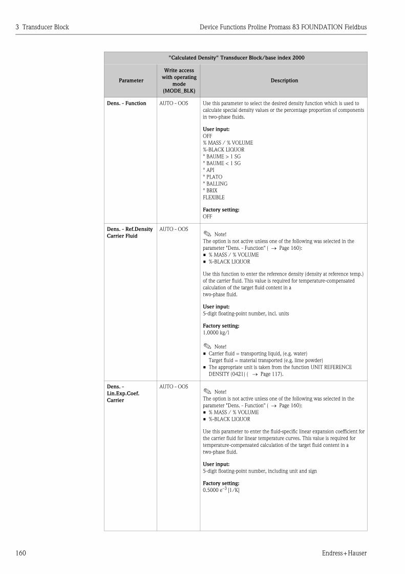
3 Transducer Block Device Functions Proline Promass 83 FOUNDATION Fieldbus
160 Endress+Hauser
Dens. - Function AUTO - OOS Use this parameter to select the desired density function which is used to
calculate special density values or the percentage proportion of components
in two-phase fluids.
User input:
OFF
% MASS / % VOLUME
%-BLACK LIQUOR
° BAUME > 1 SG
° BAUME < 1 SG
° API
° PLATO
° BALLING
° BRIX
FLEXIBLE
Factory setting:
OFF
Dens. - Ref.Density
Carrier Fluid
AUTO - OOS! Note!
The option is not active unless one of the following was selected in the
parameter "Dens. - Function" ( → Page 160):
• % MASS / % VOLUME
• %-BLACK LIQUOR
Use this function to enter the reference density (density at reference temp.)
of the carrier fluid. This value is required for temperature-compensated
calculation of the target fluid content in a
two-phase fluid.
User input:
5-digit floating-point number, incl. units
Factory setting:
1.0000 kg/l
! Note!
• Carrier fluid = transporting liquid, (e.g. water)
Target fluid = material transported (e.g. lime powder)
• The appropriate unit is taken from the function UNIT REFERENCE
DENSITY (0421) ( → Page 117).
Dens. -
Lin.Exp.Coef.
Carrier
AUTO - OOS! Note!
The option is not active unless one of the following was selected in the
parameter "Dens. - Function" ( → Page 160):
• % MASS / % VOLUME
• %-BLACK LIQUOR
Use this parameter to enter the fluid-specific linear expansion coefficient for
the carrier fluid for linear temperature curves. This value is required for
temperature-compensated calculation of the target fluid content in a
two-phase fluid.
User input:
5-digit floating-point number, including unit and sign
Factory setting:
0.5000 e–3 [1/K]
"Calculated Density" Transducer Block/base index 2000
Parameter
Write access
with operating
mode
(MODE_BLK)
Description

Device Functions Proline Promass 83 FOUNDATION Fieldbus 3 Transducer Block
Endress+Hauser 161
Dens. -
Sqr.Exp.Coef.
Carrier
AUTO - OOS! Note!
The option is not active unless one of the following was selected in the
parameter "Dens. - Function" ( → Page 160):
• % MASS / % VOLUME
• %-BLACK LIQUOR
Use this parameter to enter the fluid-specific square expansion coefficient for
the carrier fluid for non linear temperature curves. This value is required for
temperature-compensated calculation of the target fluid content in a
two-phase fluid.
User input:
5-digit floating-point number, including unit and sign
Factory setting:
0.0000 e–6 [1/K2]
Dens. - Ref.Density
Target Fluid
AUTO - OOS! Note!
The option is not active unless one of the following was selected in the
parameter "Dens. - Function" ( → Page 160):
• % MASS / % VOLUME
• %-BLACK LIQUOR
Use this parameter to enter the reference density (density at reference
temperature) of the carrier fluid. This value is required for temperature-
compensated calculation of the target fluid content in a
two-phase fluid.
User input:
5-digit floating-point number, incl. units
Factory setting:
1.0000 kg/l
! Note!
• Carrier fluid = transporting liquid, (e.g. water)
Target fluid = material transported (e.g. lime powder)
• The appropriate unit is taken from the function UNIT REFERENCE
DENSITY (0421) ( → Page 117).
Dens. -
Lin.Exp.Coef.Target
AUTO - OOS! Note!
The option is not active unless one of the following was selected in the
parameter "Dens. - Function" ( → Page 160):
• % MASS / % VOLUME
• %-BLACK LIQUOR
Use this parameter to enter the fluid-specific linear expansion coefficient for
the carrier fluid for linear temperature curves. This value is required for
temperature-compensated calculation of the target fluid content in a
two-phase fluid.
User input:
5-digit floating-point number, including unit and sign
Factory setting:
0.5000 e–3 [1/K]
"Calculated Density" Transducer Block/base index 2000
Parameter
Write access
with operating
mode
(MODE_BLK)
Description

3 Transducer Block Device Functions Proline Promass 83 FOUNDATION Fieldbus
162 Endress+Hauser
Dens. -
Sqr.Exp.Coef.Target
AUTO - OOS! Note!
The option is not active unless one of the following was selected in the
parameter "Dens. - Function" ( → Page 160):
• % MASS / % VOLUME
• %-BLACK LIQUOR
Use this parameter to enter the fluid-specific square expansion coefficient for
the carrier fluid for non linear temperature curves. This value is required for
temperature-compensated calculation of the target fluid content in a
two-phase fluid.
User input:
5-digit floating-point number, including unit and sign
Factory setting:
0.0000 e–6 [1/K2]
Dens. -
Lin.Exp.Coef.
AUTO - OOS! Note!
The option is not active unless one of the following was selected in the
parameter "Dens. - Function" ( → Page 160):
• ° BAUME < 1 SG
• ° BAUME > 1 SG
• ° API
• ° PLATO
• ° BALLING
• ° BRIX
Use this parameter to enter the fluid-specific linear expansion coefficient
(for linear temperature curves) to calculate the temperature-compensated
density functions.
User input:
5-digit floating-point number, including unit and sign
Factory setting:
0.5000 e-3 [1/K]
Dens. -
Sqr.Exp.Coef.
AUTO - OOS! Note!
The option is not active unless one of the following was selected in the
parameter "Dens. - Function"
( → Page 160):
• ° BAUME < 1 SG
• ° BAUME > 1 SG
• ° API
• ° PLATO
• ° BALLING
• ° BRIX
Use this parameter to enter the fluid-specific square expansion coefficient
(for nonlinear temperature curves) to calculate the temperature-
compensated density functions.
User input:
5-digit floating-point number, including unit and sign
Factory setting:
0.0000 e–6 [1/K2]
"Calculated Density" Transducer Block/base index 2000
Parameter
Write access
with operating
mode
(MODE_BLK)
Description

Device Functions Proline Promass 83 FOUNDATION Fieldbus 3 Transducer Block
Endress+Hauser 163
Dens. -
Ref.Temperature
AUTO - OOS! Note!
The option is only active if the OFF, °BRIX or FLEXIBLE option was not
selected in the "Dens. - Function" parameter ( → Page 160).
Use this parameter to enter the reference temperature for the density
functions.
User input:
4-digit fixed-point number, including unit and sign
Factory setting:
20 °C
Dens.- -Mode AUTO - OOS! Note!
The option is not active unless FLEXIBLE was selected in the parameter
"Dens. - Function" ( → Page 160).
Use this parameter to select a user-specific method of calculating the
concentration of the density and temperature measured.
In order to use this function, the following values are required:
• Concentration (see formula)
• Currently measured density
• Currently measured temperature
The concentration is calculated from the density and temperature as follows:
K = A0 + A1 · ρ + A2 · ρ2 + A3 · ρ3 + A4 · ρ4 + B1 · T + B2 · T2 + B3 · T3
K = Concentration
ρ = Currently measured density
A0 = Value from Dens. - A0 parameter
A1 = Value from Dens. - A1 parameter
A2 = Value from Dens. - A2 parameter
A3 = Value from Dens. - A3 parameter
A4 = Value from Dens. - A4 parameter
B1 = Value from Dens. - B1 parameter
B2 = Value from Dens. - B2 parameter
B3 = Value from Dens. - B3 parameter
T = Currently measured temperature in °C
Options:
% MASS 3D
% VOLUME 3D
% MASS 2D
% VOLUME 2D
Factory setting:
% MASS 3D
! Note!
The relationship between the individual values (concentration, density and
temperature) can also be determined via the ToF Tool-Fieldtool Package
operating program and be transmitted to the measuring device.
"Calculated Density" Transducer Block/base index 2000
Parameter
Write access
with operating
mode
(MODE_BLK)
Description

3 Transducer Block Device Functions Proline Promass 83 FOUNDATION Fieldbus
164 Endress+Hauser
Dens. -
Concentration
Selector
AUTO - OOS Use this parameter to select a concentration specification. There are four
different concentration specifications available, via which various
concentrations can be defined.
Options:
CONC. # 1 (or the name that has been defined in the parameter
"Dens. - Concentration Name" for concentration specification 1)
CONC. # 2 (or the name that has been defined in the parameter
"Dens. - Concentration Name" for concentration specification 2)
CONC. # 3 (or the name that has been defined in the parameter
"Dens. - Concentration Name" for concentration specification 3)
CONC. # 4 (or the name that has been defined in the parameter
"Dens. - Concentration Name" for concentration specification 4)
Factory setting:
CONC. # 1
! Note!
• By selecting a concentration specification and the (subsequent) relevant
settings, up to 4 different concentrations can be preconfigured and
selected when needed.
• All settings in the subsequent parameters are each only valid for the
concentration specification selected in the parameter
"Dens. - Concentration Selector".In other words, the entry or option is
assigned to the concentration specification currently selected (e.g. in the
factory setting CONC. # 1).
Dens. -
Concentration
Name
AUTO - OOS Use this parameter to assign a specific name to the concentration
specification.
User input:
Max. 8-character text, permissible: A-Z, 0-9
Factory setting:
Name of concentration specification (depends on selection in the parameter
"Dens. - Concentration Selector", e.g. "CONC. # 1").
Dens. - A0 read only Coefficient A0 entry.
User input:
5-digit floating-point number
Factory setting:
0
Dens. - A1 read only Coefficient A1 entry.
User input:
5-digit floating-point number
Factory setting:
0
Dens. - A2 read only Coefficient A2 entry.
User input:
5-digit floating-point number
Factory setting:
0
"Calculated Density" Transducer Block/base index 2000
Parameter
Write access
with operating
mode
(MODE_BLK)
Description

Device Functions Proline Promass 83 FOUNDATION Fieldbus 3 Transducer Block
Endress+Hauser 165
Dens. - A3 read only Coefficient A3 entry.
User input:
5-digit floating-point number
Factory setting:
0
Dens. - A4 read only Coefficient A4 entry.
User input:
5-digit floating-point number
Factory setting:
0
Dens. - B1 read only! Note!
The option is not active unless the % MASS 3D or % VOLUME 3D option
was selected in the parameter "Dens. - Mode" ( → Page 163).
Coefficient B1 entry.
User input:
5-digit floating-point number
Factory setting:
0
Dens. - B2 read only! Note!
The option is not active unless the % MASS 3D or % VOLUME 3D option
was selected in the parameter "Dens. - Mode" ( → Page 163).
Coefficient B2 entry.
User input:
5-digit floating-point number
Factory setting:
0
Dens. - B3 read only! Note!
The option is not active unless the % MASS 3D or % VOLUME 3D option
was selected in the parameter "Dens. - Mode" ( → Page 163).
Coefficient B3 entry.
User input:
5-digit floating-point number
Factory setting:
0
Amp. Device Type read only This parameter is only used for service purposes.
"Calculated Density" Transducer Block/base index 2000
Parameter
Write access
with operating
mode
(MODE_BLK)
Description

3 Transducer Block Device Functions Proline Promass 83 FOUNDATION Fieldbus
166 Endress+Hauser
3.8 "Viscosity" Transducer Block parameters
! Note!
• The parameters of the "Viscosity" Transducer Block are ready for use and can be configured if the
"Viscosity" add-on is installed in the measuring device (order option). Otherwise the value "NaN"
(not-a-number) or "Not licensed" is displayed in a parameter.
• This order option is only available for Proline Promass 83I.
The following table shows the Endress+Hauser-specific parameters of the "Viscosity" Transducer
Block. These can only be changed after entering a release code in the "Access - Code" parameter.
! Note!
FOUNDATION Fieldbus parameters are described in the Operating Instructions "FOUNDATION
Fieldbus Overview" (BA013S) (available at: → www.endress.com → download).
"Viscosity" Transducer Block/base index 2100
Parameter
Write access
with operating
mode
(MODE_BLK)
Description
Access - Code AUTO - OOS All data of the measuring system are protected against inadvertent change.
Only when the code has been entered in this parameter can the
manufacturer-specific parameters be programmed and the device
configuration modified.
You can enable programming by entering:
• Code 83 (factory setting)
• Personal code ( → Page 135)
User input:
Max. 4-digit number (0 to 9999)
! Note!
• If the write protection is enabled then access to the manufacturer-specific
parameters is blocked even if the right code is entered. Write protection
can be activated and deactivated by means of jumpers on the I/O board
(→ See Operating Instructions for Proline Promass 83 FOUNDATION
Fieldbus, BA065D).
• You can disable programming again by entering any number (other than
the release code) in this parameter.
• The Endress+Hauser service organization can be of assistance if you
mislay your personal code.
• Certain parameters are not accessible unless a special
service code is entered. This service code is known only to the
Endress+Hauser service organization. Please contact your
Endress+Hauser service center if you require clarification.
• The entry made here does not affect the local display. Programming via
the function matrix thus has to be enabled separately.
Access - Status read only Use this parameter to display the current status of the possibilities for
accessing the manufacturer-specific parameters of the device.
Display:
• LOCKED (parameterization disabled)
• ACCESS CUSTOMER (parameterization enabled)
• ACCESS SERVICE (parameterization enabled, access to service level)
Visc. - Dyn.Viscosity read only Use this function to view the dynamic viscosity.
Display:
5-digit floating-point number, incl. unit.
(e.g. 462.87 cP; 731.63 mPa·s etc.)

Device Functions Proline Promass 83 FOUNDATION Fieldbus 3 Transducer Block
Endress+Hauser 167
Visc. - Kin.Viscosity read only Use this function to view the calculated kinematic viscosity.
Display:
5-digit floating-point number, incl. unit.
(e.g. 5.5445 mm2/s; 1.4359 cSt)
Visc. -
Temp.Comp.Dyn.
Viscosity
read only Use this function to view the temperature-compensated dynamic viscosity.
Display:
5-digit floating-point number, incl. unit.
(e.g. 462.87 cP; 731.63 mPa·s etc.)
Visc. - Temp.Kin.
Viscosity
read only Use this function to view the temperature-compensated kinematic viscosity.
Display:
5-digit floating-point number, incl. unit.
(e.g. 5.5445 mm2/s; 1.4359 cSt)
Visc. - Unit Dyn.
Viscosity
AUTO - OOS For selecting the unit required and displayed for measuring the dyn. viscosity.
Options:
• Pa·s
• mPa·s
• P
• cP
Factory setting:
cP
Visc. - Unit Kin.
Viscosity
AUTO - OOS For selecting the unit required and displayed for measuring the kinem. viscosity.
Options:
• m2/s
• mm2/s
• St
• cSt
Factory setting:
cSt
Visc. -
Temp.Comp.Model
AUTO - OOS Use this function to select a formula model for temperature compensation.
Depending on the thermal behavior, you can select the model that most
accurately depicts the function → See Special Documentation on viscosity
measurement for Proline Promass 83I, SD102D.
Options:
Power law
Exponential
Polynomial
Factory setting:
Polynomial
Visc. -
Ref.Temperature
AUTO - OOS Use this function to enter the reference temperature which should act as the
reference point.
User input:
7-digit floating-point number
Factory setting:
0
Reference quantity:
°C
"Viscosity" Transducer Block/base index 2100
Parameter
Write access
with operating
mode
(MODE_BLK)
Description

3 Transducer Block Device Functions Proline Promass 83 FOUNDATION Fieldbus
168 Endress+Hauser
Visc. - X1 AUTO - OOS Use this function to enter the compensation coefficient X1 (calculation
→ See Special Documentation on viscosity measurement for Proline
Promass 83I, SD102D).
User input:
7-digit floating-point number
Factory setting:
0
Visc. - X2 AUTO - OOS Use this function to enter the compensation coefficient X2 (calculation
→ See Special Documentation on viscosity measurement for Proline
Promass 83I, SD102D).
User input:
7-digit floating-point number
Factory setting:
0
Visc. - Y1 AUTO - OOS This parameter is only used for service purposes.
Amp. Device Type read only This parameter is only used for service purposes.
"Viscosity" Transducer Block/base index 2100
Parameter
Write access
with operating
mode
(MODE_BLK)
Description

Device Functions Proline Promass 83 FOUNDATION Fieldbus 3 Transducer Block
Endress+Hauser 169
3.9 "Advanced Diagnostics" Transducer Block parameters
! Note!
The parameters of the "Advanced Diagnostics" Transducer Block are ready for use and can be
configured if the "Advanced Diagnostics" add-on is installed in the measuring device (order option).
Otherwise the value "NaN" (not-a-number) or "Not licensed" is displayed in a parameter.
The following table shows the Endress+Hauser-specific parameters of the "Advanced Diagnostics"
Transducer Block. These can only be changed after entering a release code in the "Access - Code"
parameter.
! Note!
FOUNDATION Fieldbus parameters are described in the Operating Instructions "FOUNDATION
Fieldbus Overview" (BA013S) (available at: → www.endress.com → download).
"Advanced Diagnostics" Transducer Block/base index 2200
Parameter
Write access
with operating
mode
(MODE_BLK)
Description
Access - Code AUTO - OOS All data of the measuring system are protected against inadvertent change.
Only when the code has been entered in this parameter can the
manufacturer-specific parameters be programmed and the device
configuration modified.
You can enable programming by entering:
• Code 83 (factory setting)
• Personal code ( → Page 135)
User input:
Max. 4-digit number (0 to 9999)
! Note!
• If the write protection is enabled then access to the manufacturer-specific
parameters is blocked even if the right code is entered. Write protection
can be activated and deactivated by means of jumpers on the I/O board
(→ See Operating Instructions for Proline Promass 83 FOUNDATION
Fieldbus, BA065D).
• You can disable programming again by entering any number (other than
the release code) in this parameter.
• The Endress+Hauser service organization can be of assistance if you
mislay your personal code.
• Certain parameters are not accessible unless a special
service code is entered. This service code is known only to the
Endress+Hauser service organization. Please contact your
Endress+Hauser service center if you require clarification.
• The entry made here does not affect the local display. Programming via
the function matrix thus has to be enabled separately.
Access - Status read only Use this parameter to display the current status of the possibilities for
accessing the manufacturer-specific parameters of the device.
Display:
• LOCKED (parameterization disabled)
• ACCESS CUSTOMER (parameterization enabled)
• ACCESS SERVICE (parameterization enabled, access to service level)

3 Transducer Block Device Functions Proline Promass 83 FOUNDATION Fieldbus
170 Endress+Hauser
Adv. -
Ref.Cond.User
AUTO - OOS Use this parameter to start determining the user reference status. The
following values are determined:
• MASS FLOW
• DENSITY
• REFERENCE DENSITY
• TEMPERATURE
• TUBE DAMPING
• ELECTRODYNAMIC SENSORS
• OPERATING FREQUENCY FLUCTUATION
• TUBE DAMPING FLUCTUATION
Options:
CANCEL
START
Factory setting:
CANCEL
Adv. - Select
Ref.Condition
AUTO - OOS Use this parameter to select the reference status which should be used to
compare the advanced diagnostics parameters (see parameter
"Adv. - Acquisition Mode" → Page 171).
Options:
FACTORY
USER
Factory setting:
FACTORY
Adv. -
Warning Mode
AUTO - OOS Use this parameter to determine whether a warning should be generated
when there is a deviation between the reference status (FACTORY or USER,
see parameter "Adv. - Select Ref.Condition") and the current measuring
values.
The values of the following parameters are compared to the reference status :
• Mass Flow - Actual Value ( → Page 172)
• Density - Actual Value ( → Page 173)
• Ref.Density - Actual Value ( → Page 174)
• Temperature - Actual Value ( → Page 175)
• Tube Damping - Actual Value ( → Page 176)
• El.Dyn.Sens. - Actual Value ( → Page 177)
• Freq.Fluct. - Actual Value ( → Page 178)
• Tube Damp.Fluct. - Actual Value ( → Page 179)
Options:
OFF
ON
Factory setting:
ON
"Advanced Diagnostics" Transducer Block/base index 2200
Parameter
Write access
with operating
mode
(MODE_BLK)
Description

Device Functions Proline Promass 83 FOUNDATION Fieldbus 3 Transducer Block
Endress+Hauser 171
Adv. -
Acquisition Mode
AUTO - OOS Use this parameter to specify whether the advanced diagnostics parameters
should be determined on a periodical or single-shot basis.
Options:
OFF
PERIODICAL
SINGLE SHOT
Factory setting:
OFF
! Note!
See the Chapter on "Commissioning" in the Operating Instructions Proline
Promass 83, BA 065D/06/en for more information on advanced
diagnostics.
Adv. -
Acquisition Period
AUTO - OOS! Note!
This option is not active unless PERIODICAL was selected in the
parameter "Adv. - Acquisition Mode".
Use this parameter to specify the time interval after which the advanced
diagnostics parameters should be recorded. The time interval starts with the
confirmation of the input.
User input:
0 to 99999 s
Factory setting:
3600 s
! Note!
A reference status must be defined prior to determining the diagnosis
parameters, see parameter "Adv. - Select Ref.Condition".
Adv. -
Acquisition Do
AUTO - OOS! Note!
This option is not active unless SINGLE SHOT was selected in the
parameter "Adv. - Acquisition Mode".
Use this parameter to start determining the advanced diagnostics parameters
on a single-shot basis.
Options:
CANCEL
START
Factory setting:
CANCEL
! Note!
A reference status must be defined prior to determining the diagnosis
parameters, see parameter "Adv. - Select Ref.Condition".
Adv. - Reset History AUTO - OOS Use this function to delete all history values.
Options:
NO
YES
Factory setting:
NO
Mass Flow -
Ref.Value Factory
read only The reference value for the mass flow appears on the display.
Display:
5-digit floating-point number, including unit and sign
"Advanced Diagnostics" Transducer Block/base index 2200
Parameter
Write access
with operating
mode
(MODE_BLK)
Description
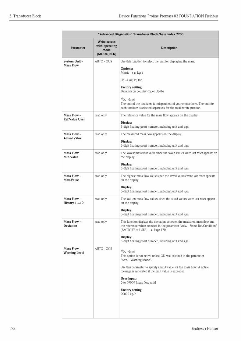
3 Transducer Block Device Functions Proline Promass 83 FOUNDATION Fieldbus
172 Endress+Hauser
System Unit -
Mass Flow
AUTO - OOS Use this function to select the unit for displaying the mass.
Options:
Metric → g; kg; t
US → oz; lb; ton
Factory setting:
Depends on country (kg or US-lb)
! Note!
The unit of the totalizers is independent of your choice here. The unit for
each totalizer is selected separately for the totalizer in question.
Mass Flow -
Ref.Value User
read only The reference value for the mass flow appears on the display.
Display:
5-digit floating-point number, including unit and sign
Mass Flow -
Actual Value
read only The measured mass flow appears on the display.
Display:
5-digit floating-point number, including unit and sign
Mass Flow -
Min.Value
read only The lowest mass flow value since the saved values were last reset appears on
the display.
Display:
5-digit floating-point number, including unit and sign
Mass Flow -
Max.Value
read only The highest mass flow value since the saved values were last reset appears
on the display.
Display:
5-digit floating-point number, including unit and sign
Mass Flow -
History 1…10
read only The last ten mass flow values since the saved values were last reset appear
on the display.
Display:
5-digit floating-point number, including unit and sign
Mass Flow -
Deviation
read only This function displays the deviation between the measured mass flow and
the reference values selected in the parameter "Adv. - Select Ref.Condition"
(FACTORY or USER) → Page 170.
Display:
5-digit floating-point number, including unit and sign
Mass Flow -
Warning Level
AUTO - OOS! Note!
This option is not active unless ON was selected in the parameter
"Adv. - Warning Mode".
Use this parameter to specify a limit value for the mass flow. A notice
message is generated if the limit value is exceeded.
User input:
0 to 99999 [mass flow unit]
Factory setting:
90000 kg/h
"Advanced Diagnostics" Transducer Block/base index 2200
Parameter
Write access
with operating
mode
(MODE_BLK)
Description

Device Functions Proline Promass 83 FOUNDATION Fieldbus 3 Transducer Block
Endress+Hauser 173
Density -
Ref.Value Factory
read only The reference value for the density appears on the display.
Display:
5-digit floating-point number, incl. units
System Unit
Density
AUTO - OOS Use this parameter to select the unit for displaying the density.
The unit you select here is also valid for:
• Simulation
• Density response value for EPD
• Density adjustment value
Options:
Metric → g/cm3; g/cc; kg/dm3; kg/l; kg/m3; SD 4 °C, SD 15 °C,
SD 20 °C; SG 4 °C, SG 15 °C, SG 20 °C
US → lb/ft3; lb/gal; lb/bbl (normal fluids); lb/bbl (beer);
lb/bbl (petrochemicals); lb/bbl (filling tanks)
Imperial → lb/gal; lb/bbl (beer); lb/bbl (petrochemicals)
Factory setting:
kg/l
SD = Specific Density, SG = Specific Gravity
The specific density is the ratio of fluid density to water density (at water
temperature = 4, 15, 20 °C).
Density -
Ref.Value User
read only The reference value for the density appears on the display.
Display:
5-digit floating-point number, incl. units
Density -
Actual Value
read only The measured density appears on the display.
Display:
5-digit floating-point number, incl. units
Density - Min.Value read only The lowest density value since the saved values were last reset appears on
the display.
Display:
5-digit floating-point number, incl. units
Density - Max.Value read only The highest density value since the saved values were last reset appears on
the display.
Display:
5-digit floating-point number, incl. units
Density -
History 1…10
read only The last ten density values since the saved values were last reset appear on
the display.
Display:
5-digit floating-point number, incl. units
Density - Deviation read only This function displays the deviation between the measured density and the
reference values selected in the parameter "Adv. - Select Ref.Condition"
(FACTORY or USER) → Page 170.
Display:
5-digit floating-point number, incl. units
"Advanced Diagnostics" Transducer Block/base index 2200
Parameter
Write access
with operating
mode
(MODE_BLK)
Description

3 Transducer Block Device Functions Proline Promass 83 FOUNDATION Fieldbus
174 Endress+Hauser
Density - Warning
Level
AUTO - OOS! Note!
This option is not active unless ON was selected in the parameter
"Adv. - Warning Mode".
Use this function to specify a limit value for the density. A notice message is
generated if the limit value is exceeded.
User input:
0 to 99999 [%]
Factory setting:
100%
Ref.Density -
Ref.Value Factory
read only The reference value for the reference density appears on the display.
Display:
5-digit floating-point number, incl. units
System Unit -
Ref.Density
AUTO - OOS Use this parameter to select the unit for displaying the reference density.
The unit you select here is also valid for:
• Simulation
• Fixed reference density (for calculation of corrected volume flow)
Options:
Metric → kg/Nm3; kg/Nl
US → g/Scc; kg/Sm3; lb/Scf
Factory setting:
kg/Nl
Ref.Density -
Ref.Value User
read only The reference value for the reference density appears on the display.
Display:
5-digit floating-point number, incl. units
Ref.Density -
Actual Value
read only The measured reference density appears on the display.
Display:
5-digit floating-point number, incl. units
Ref.Density -
Min. Value
read only The lowest reference density value since the saved values were last reset
appears on the display.
Display:
5-digit floating-point number, incl. units
Ref.Density -
Max.Value
read only The highest reference density value since the saved values were last reset
appears on the display.
Display:
5-digit floating-point number, incl. units
Ref.Density -
History 1…10
read only The last ten reference density values since the saved values were last reset
appear on the display.
Display:
5-digit floating-point number, incl. units
Ref.Density -
Deviation
read only This function displays the deviation between the measured reference density
and the reference values selected in the parameter "Adv. - Select
Ref.Condition" (FACTORY or USER) → Page 170.
Display:
5-digit floating-point number, incl. units
"Advanced Diagnostics" Transducer Block/base index 2200
Parameter
Write access
with operating
mode
(MODE_BLK)
Description

Device Functions Proline Promass 83 FOUNDATION Fieldbus 3 Transducer Block
Endress+Hauser 175
Ref.Density -
Warning Level
AUTO - OOS! Note!
This option is not active unless ON was selected in the parameter
"Adv. - Warning Mode".
Use this parameter to specify a limit value for the reference density. A notice
message is generated if the limit value is exceeded.
User input:
0 to 99999 [%]
Factory setting:
100%
Temperature -
Ref.Value Factory
read only The reference value for the temperature appears on the display.
Display:
5-digit floating-point number, including unit and sign
System Unit
Temperature
AUTO - OOS Use this function to select the unit for displaying the temperature.
The unit you select here is also valid for:
• Simulation
• Reference temperature (for corrected volume measurement with
measured reference density)
Options:
°C (Celsius)
K (Kelvin)
°F (Fahrenheit)
R (Rankine)
Factory setting:
°C
Temperature -
Ref.Value User
read only The reference value for the temperature appears on the display.
Display:
5-digit floating-point number, including unit and sign
Temperature -
Actual Value
read only The currently measured temperature appears on the display.
Display:
5-digit floating-point number, including unit and sign
Temperature -
Min.Value
read only The lowest temperature value since the saved values were last reset appears
on the display.
Display:
5-digit floating-point number, including unit and sign
Temperature -
Max.Value
read only The highest temperature value since the saved values were last reset appears
on the display.
Display:
5-digit floating-point number, including unit and sign
Temperature -
History 1…10
read only The last ten temperature values since the saved values were last reset appear
on the display.
Display:
5-digit floating-point number, including unit and sign
"Advanced Diagnostics" Transducer Block/base index 2200
Parameter
Write access
with operating
mode
(MODE_BLK)
Description

3 Transducer Block Device Functions Proline Promass 83 FOUNDATION Fieldbus
176 Endress+Hauser
Temperature -
Deviation
read only This function displays the deviation between the measured temperature and
the reference values selected in the parameter "Adv. - Select Ref.Condition"
(FACTORY or USER) → Page 170.
Display:
5-digit floating-point number, including unit and sign
Temperature -
Warning Level
AUTO - OOS! Note!
This option is not active unless ON was selected in the parameter
"Adv. - Warning Mode".
Use this parameter to specify a limit value for the temperature. A notice
message is generated if the limit value is exceeded.
User input:
0 to 99999 °C
Factory setting:
100 °C
Tube Damping -
Ref.Value Factory
read only The reference value for tube damping appears on the display.
Display:
5-digit floating-point number
Tube Damping -
Ref.Value User
AUTO - OOS The reference value for tube damping appears on the display.
Display:
5-digit floating-point number
Tube Damping -
Actual Value
read only The measured tube damping appears on the display.
Display:
5-digit floating-point number
Tube Damping -
Min.Value
read only The lowest tube damping value since the saved values were last reset
appears on the display.
Display:
5-digit floating-point number
Tube Damping -
Max.Value
read only The highest tube damping value since the saved values were last reset
appears on the display.
Display:
5-digit floating-point number
Tube Damping -
History 1…10
read only The last ten tube damping values since the saved values were last reset
appears on the display.
Display:
5-digit floating-point number
Tube Damping -
Deviation
read only This function displays the deviation between the measured tube damping
and the reference values selected in the parameter "Adv. - Select
Ref.Condition" (FACTORY or USER) → Page 170.
Display:
5-digit floating-point number
"Advanced Diagnostics" Transducer Block/base index 2200
Parameter
Write access
with operating
mode
(MODE_BLK)
Description

Device Functions Proline Promass 83 FOUNDATION Fieldbus 3 Transducer Block
Endress+Hauser 177
Tube Damping -
Warning Level
AUTO - OOS! Note!
This option is not active unless ON was selected in the parameter
"Adv. - Warning Mode".
Use this parameter to specify a limit value for tube damping. A notice
message is generated if the limit value is exceeded.
User input:
0 to 99999 [%]
Factory setting:
1000%
El.Dyn.Sens. -
Ref.Value Factory
read only The reference value for the electrodynamic sensors appears on the display.
Display:
5-digit floating-point number
El.Dyn.Sens. -
Ref.Value User
read only The reference value for the electrodynamic sensors appears on the display.
Display:
5-digit floating-point number
El.Dyn.Sens. -
Actual Value
read only The measuring values for the electrodynamic sensors appear on the display.
Display:
5-digit floating-point number
El.Dyn.Sens. -
Min. Value
read only The lowest value of the electrodynamic sensors since the saved values were
last reset appears on the display.
Display:
5-digit floating-point number
El.Dyn.Sens. -
Max.Value
read only The highest value of the electrodynamic sensors since the saved values were
last reset appears on the display.
Display:
5-digit floating-point number
El.Dyn.Sens. -
History 1…10
read only The last ten values of the electrodynamic sensors since the saved values
were last reset appear on the display.
Display:
5-digit floating-point number
El.Dyn.Sens. -
Deviation
read only This function displays the deviation between the measured values for the
electrodynamic sensors and the reference values selected in the parameter
"Adv. - Select Ref.Condition" (FACTORY or USER) → Page 170.
Display:
5-digit floating-point number
"Advanced Diagnostics" Transducer Block/base index 2200
Parameter
Write access
with operating
mode
(MODE_BLK)
Description

3 Transducer Block Device Functions Proline Promass 83 FOUNDATION Fieldbus
178 Endress+Hauser
El.Dyn.Sens. -
Warning Level
AUTO - OOS! Note!
This option is not active unless ON was selected in the parameter
"Adv. - Warning Mode".
Use this parameter to specify a limit value for the electrodynamic sensors.
A notice message is generated if the limit value is exceeded.
User input:
0 to 99999 [%]
Factory setting:
100%
Freq.Fluct. -
Ref.Value Factory
read only The reference value for the fluctuation of the operating frequency appears on
the display.
Display:
5-digit floating-point number, Hz
Freq.Fluct. -
Ref.Value User
read only The reference value for the fluctuation of the operating frequency appears on
the display.
Display:
5-digit floating-point number, Hz
Freq.Fluct. -
Actual Value
read only The measured fluctuation of the operating frequency appears on the display.
Display:
5-digit floating-point number, Hz
Freq.Fluct. -
Min.Value
read only The lowest value of the operating frequency fluctuation since the saved
values were last reset appears on the display.
Display:
5-digit floating-point number, Hz
Freq.Fluct. -
Max.Value
read only The highest value of the operating frequency fluctuation since the saved
values were last reset appears on the display.
Display:
5-digit floating-point number, Hz
Freq.Fluct. -
History 1…10
read only The last ten values of the operating frequency fluctuation since the saved
values were last reset appear on the display.
Display:
5-digit floating-point number, Hz
Freq.Fluct. -
Deviation
read only This function displays the deviation between the measured fluctuation in
operating frequency and the reference values selected in the parameter
"Adv. - Select Ref.Condition" (FACTORY or USER) → Page 170.
Display:
5-digit floating-point number, Hz
Freq.Fluct. -
Warning Level
AUTO - OOS! Note!
This option is not active unless ON was selected in the parameter
"Adv. - Warning Mode".
Use this function to specify a limit value for the operating frequency
fluctuation. A notice message is generated if the limit value is exceeded.
User input:
0 to 99999 Hz
Factory setting:
1000 Hz
"Advanced Diagnostics" Transducer Block/base index 2200
Parameter
Write access
with operating
mode
(MODE_BLK)
Description

Device Functions Proline Promass 83 FOUNDATION Fieldbus 3 Transducer Block
Endress+Hauser 179
Tube Damp.Fluct. -
Ref.Value Factory
read only The reference value for the fluctuation of the tube damping appears on the
display.
Display:
5-digit floating-point number
Tube Damp.Fluct. -
Ref.Value User
read only The reference value for the fluctuation of the tube damping appears on the
display.
Display:
5-digit floating-point number
Tube Damp.Fluct. -
Actual Value
read only The measured fluctuation of the tube damping appears on the display.
Display:
5-digit floating-point number
Tube Damp.Fluct. -
Min.Value
read only The lowest value of the tube damping since the saved values were last reset
appears on the display.
Display:
5-digit floating-point number
Tube Damp.Fluct. -
Max.Value
read only The highest value of the tube damping fluctuation since the saved values
were last reset appears on the display.
Display:
5-digit floating-point number
Tube Damp.Fluct. -
History 1…10
read only The last ten values of the tube damping fluctuation since the saved values
were last reset appear on the display.
Display:
5-digit floating-point number
Tube Damp.Fluct. -
Deviation
read only This function displays the deviation between the measured fluctuation in
tube damping and the reference values selected in the parameter "Adv. -
Select Ref.Condition" (FACTORY or USER) → Page 170.
Display:
5-digit floating-point number
Tube Damp.Fluct. -
Warning Level
AUTO - OOS! Note!
This option is not active unless ON was selected in the
parameter "Adv. - Warning Mode".
Use this parameter to specify a limit value for tube damping fluctuation. A
notice message is generated if the limit value is exceeded.
User input:
0 to 99999
Factory setting:
1000
Amp. Device Type read only This parameter is only used for service purposes.
"Advanced Diagnostics" Transducer Block/base index 2200
Parameter
Write access
with operating
mode
(MODE_BLK)
Description

4 Function blocks Device Functions Proline Promass 83 FOUNDATION Fieldbus
180 Endress+Hauser
4 Function blocks
The function blocks contain the basic automation functions of the field device. We distinguish
between different function blocks, e.g. Analog Input function block, PID function block
(PID controller), etc.
Each of these function blocks is used to execute different application functions. This means that
local control functions, for example, can be carried out directly in the field, and device errors such
as amplifier errors are reported to the automation system automatically.
The function blocks process the input values in accordance with their specific algorithm and their
internally available parameters. They generate output values that are made available to other
function blocks for further processing by linking the individual function blocks with each other.

Device Functions Proline Promass 83 FOUNDATION Fieldbus 5 Analog Input function block
Endress+Hauser 181
5 Analog Input function block
In the Analog Input function block (AI) the process variables from the Transducer Block are
prepared for the subsequent automation functions (e.g. scaling, limit value processing). The
automation function is defined by the connections of the outputs.
5.1 Signal processing
The figure shows the internal structure of the Analog Input function blocks available:
A0004762-en
Fig. 3 : Internal structure of the individual Analog Input function blocks
A0003800
OUT = output value and output status of the Analog Input function block
OUT
AI
SIMULATE
XD_SCALE OUT_SCALE
XD_SCALE = OUT_SCALE
XD_SCALE OUT_SCALE
Direct
Indirect
Value, Status
Analog Input 1
L_TYPE
LOW_CUTCutoff
PV_FTIME
PV
MODE
AUTO
O/S
MAN
Filter
HI_HI_ALM
XD_SCALE OUT_SCALE
FIELD_VAL
Indirectsquare root
ALARM_HYS
HI_ALM
LO_LO_ALM
LO_ALM
Alarm detection
HI_HI
HI
LOLO_LO
TB Flow
TB Totalizer
TB Concentration
TB Viscosity
TB AdvancedDiagnostics
Analog Input 5
Analog Input 6
Analog Input 7
Analog Input 8
Analog Input 2
Analog Input 3
Analog Input 4
OUT
CHANNEL
CH 1 Mass Flow
CH 2 Volume Flow
CH 3 Corr. Vol. FlowCH 4 Density
CH 8 Totalizer 2
CH 9 Totalizer 3
CH 5 Ref. Density
CH 6 Temperature
CH 7 Totalizer 1
CH 40…51 (optional)
CH 70…77 (optional)
CH 90…93 (optional)

5 Analog Input function block Device Functions Proline Promass 83 FOUNDATION Fieldbus
182 Endress+Hauser
The Analog Input function blocks receive their input values from the Transducer Blocks.
The parameter CHANNEL is used to select which input value is to be processed in an Analog Input
function block.
Factory-based configuration of the Transducer Blocks → Page 111 ff.
The parameter group SIMULATE allows you to replace the input value with a simulation value and
to activate simulation. By specifying the status and the simulation value the reaction of the complete
Analog Input function block can be tested.
! Note!
The simulation mode is activated by means of jumpers on the I/O board (→ See Operating
Instructions for Proline Promass 83 FOUNDATION Fieldbus, BA065D).
The parameter L_TYPE is used to select the linearization type of the input or simulation value:
• Direct signal conversion
The value is forwarded without conversion (XD_SCALE = OUT_SCALE). Select this option if the
input value is already in the physical unit you want.
• Indirect signal conversion
With this setting the measured value from the Transducer Block (input value) is re-scaled linearly
via the input scaling XD_SCALE to the desired output range OUT_SCALE (further information
on rescaling of the input value can be found on → Page 185).
• Indirect signal conversion with square root
With this setting the measured value from the Transducer Block (input value) is re-scaled via the
parameter group XD_SCALE and recalculated using a square root function. It is then rescaled
again to the desired output range via the parameter group OUT_SCALE.
The parameter LOW_CUT allows a limit value to be specified for the low flow cut off. The low flow
cut off is activated via the parameter IO_OPTS. If the converted primary value (PV) is below the
limit value then it is set to a value of "Zero".
In the parameter PV_FTIME a filter time can be specified for filtering the converted primary value
(PV). If a time of 0 seconds is specified then no filtration takes place.
The parameter group MODE_BLK is used to select the operating mode of the Analog Input function
block. If the operating mode MAN (manual) is selected then the output value OUT can be specified
directly.
The output value OUT is compared with warning and alarm limits (e.g. HI_LIM, LO_LO_LIM, etc.)
that can be entered via various parameters. If one of these limit values is violated then a limit value
process alarm (e.g. HI_ALM, LO_LO_ALM, etc.) is triggered.

Device Functions Proline Promass 83 FOUNDATION Fieldbus 5 Analog Input function block
Endress+Hauser 183
5.2 Important functions and parameters of the
Analog Input function blocks
The most important functions and parameters of the Analog Input function blocks are listed below.
! Note!
All the FOUNDATION Fieldbus parameters available are described in the Operating Instructions
"FOUNDATION Fieldbus Overview" (BA013S) (available at: → www.endress.com → download).
5.2.1 Selecting the operating mode
The operating mode is configured via the MODE_
BLK parameter group. The Analog Input function block supports the following operating modes:
• AUTO (automatic mode)
• MAN (manual mode)
• OOS (out of service)
! Note!
The block status OOS is also shown via the parameter BLOCK_ERR. In operating mode OOS, if
write protection is not enabled, you can access all the write parameters without restriction.
5.2.2 Assignment of the process variable
The Promass 83 FOUNDATION Fieldbus has eight Analog Input function blocks. The process
variables of the Transducer Block that are to be processed are assigned via the parameter
CHANNEL.
Factory-based configuration of the Transducer Blocks → Page 111 ff.
5.2.3 Linearization types
In an Analog Input function block, the input value of a Transducer Block can be linearized using the
parameter L_TYPE. The following types of linearization are available:
• Direct
With this setting the measured value from the Transducer Block (input value) bypasses the
linearization function and is looped unchanged with the same unit through the Analog Input
function block.
• Indirect
With this setting the measured value from the Transducer Block (input value) is re-scaled linearly
via the input scaling XD_SCALE to the desired output range OUT_SCALE.
• Indirect Square Root
With this setting the measured value from the Transducer Block (input value) is re-scaled via the
parameter group XD_SCALE and recalculated using an evolution function. It is then rescaled
again to the desired output range via the parameter group OUT_SCALE.

5 Analog Input function block Device Functions Proline Promass 83 FOUNDATION Fieldbus
184 Endress+Hauser
5.2.4 Selection of units
A change in the unit for a process variable is defined in the relevant Analog Input function block, in
the parameter group XD_SCALE via the element UNIT.
If an unsuitable unit is selected, the function block changes to the OOS mode (out of service).
! Note!
• If the "Direct" type of linearization was selected via the L_TYPE parameter, the setting of the
XD_SCALE and OUT_SCALE parameter groups must be identical; otherwise, the function block
remains in the OOS operating mode and the "BLOCK CONFIG ERROR" block error is displayed
in the BLOCK_ERROR parameter.
• The system units selected in the Transducer Blocks in question do not have any effect on the
setting of the system units in the Analog Input function block. The units are specified
independently of one another and must be configured separately. The unit selected in the
Transducer Blocks is only used for the local display, EPD adjustment, low flow cut off and for
simulation.
5.2.5 Status of the output value OUT
The status of the parameter group OUT communicates to the subsequent function blocks the status
of the Analog Input function block and the validity of the output value OUT. The following status
values can be displayed:
• GOOD_NON_CASCADE
The output value OUT is valid and can be used for further processing.
• UNCERTAIN
The output value OUT can only be used for further processing to a limited extent. The status tells
the downstream function blocks that a "notice message" is present in the device, e.g. arising from
active positive zero return or simulation.
• BAD
The output value OUT is invalid. The following causes are possible:
– The Analog Input function block is in the OOS operating mode.
– The Resource Block is in operating mode OOS.
– The "Flow" or "Totalizer" Transducer Block is in the OOS operating mode. The Analog Input
function block can only process the input value of the Transducer Block in question if the
operating mode is set to AUTO.
– A "fault message" is present in the device arising from a critical device error, e.g. an electronics
module defect.
! Note!
• The status of the device (block error) is displayed by means of the BLOCK_ERR parameter.
• Detailed information on the current device status is displayed via the "Diagnosis" Transducer
Block in the parameter "Diag. - Act.Sys.Condition". A list of all the error messages, including
remedial measures, can be found in the Operating Instructions for Proline Promass 83
FOUNDATION Fieldbus (BA065D).

Device Functions Proline Promass 83 FOUNDATION Fieldbus 5 Analog Input function block
Endress+Hauser 185
5.2.6 Simulation of input/output
Parameters of the Analog Input function block allow simulation of the input and output of the
function block:
1. Simulation of the input of the Analog Input function block:
The parameter group SIMULATE can be used to specify the input value (measured value and
status). Since the simulation value runs through the entire function block, all the parameter
settings of the block can be checked.
! Note!
If simulation is blocked by the jumper on the I/O board then simulation mode cannot be activated
in the parameter SIMULATE. In the Resource Block, the parameter BLOCK_ERROR shows whether
simulation of the Analog Input function block is possible.
2. Simulation of the output of the Analog Input function block:
Set the operating mode in the parameter group MODE_BLK to MAN and specify the desired
output value directly in the parameter OUT.
5.2.7 Diagnosis
The status of the device is displayed via the BLOCK_ERR parameter specified in the FOUNDATION
Fieldbus specification.
Detailed information on the current device status is displayed via the "Diagnosis" Transducer Block
in the manufacturer-specific parameter "Diag. - Act.Sys.Condition" ( → Page 131).
For more information on rectifying errors → See Operating Instructions for Proline Promass 83
FOUNDATION Fieldbus (BA065D), "Troubleshooting" section.
5.2.8 Rescaling the input value
In the Analog Input function block the input value or input range can be scaled in accordance with
the automation requirements.
Example:
• The system unit in the Transducer Block is kg/h.
• The measurement range of the sensor is 0 to 30 kg/h.
• The output range to the process control system should be 0 to 100%.
The Analog Input function block must be configured as follows:
• Parameter CHANNEL
Select: CHANNEL → 1 = Mass flow
• Parameter L_TYPE
Select: L_TYPE = Indirect
The process variable "Volume flow" from the "Flow" Transducer Block is rescaled linearly in the
AI Block via input scaling XD_SCALE to the desired output range OUT_SCALE.
• Parameter group XD_SCALE
XD_SCALE 0 % = 0
XD_SCALE 100 % = 30
XD_SCALE UNIT = kg/h

5 Analog Input function block Device Functions Proline Promass 83 FOUNDATION Fieldbus
186 Endress+Hauser
• Parameter group OUT_SCALE
The result is that with an input value of, for example, 15 kg/h a value of 50% is output via the
parameter OUT.
A0004766-en
Fig. 4 : Rescaling the input value (example)
5.2.9 Limit values
The limit values are based on the output value OUT. If the output value OUT exceeds or does not
reach the defined limit values then an alarm is sent to the fieldbus host system via the limit value
process alarms. The following limit values can be defined:
• HI_HI_LIM (upper alarm limit)
• HI_LIM (upper pre-warning limit)
• LO_LO_LIM (lower alarm limit)
• LO_LIM (lower pre-warning limit)
5.2.10 Alarm detection and processing
Process alarms provide information on particular block statuses and block events. The status of the
process alarms is communicated to the fieldbus host system via the parameter BLOCK_ALM. The
parameter ACK_OPTION specifies whether an alarm must be acknowledged via the fieldbus host
system.
The following process alarms are generated by the Analog Input function block:
Block process alarms
A block process alarm is triggered via the BLOCK_ERR parameter. The parameter BLOCK_ALM is
used to show the block process alarms and communicate them to the fieldbus host system. The
following process alarms can be generated by the Analog Input function block:
• SIMULATE ACTIVE
• INPUT FAILURE
• OUT OF SERVICE
• BLOCK CONFIG ERROR
If the option of the process alarm (BLOCK ALM) has not been enabled in the parameter
ACK_OPTION, the process alarms must be acknowledged in the parameter BLOCK_ALM.
OUT_SCALE 0 % = 0
OUT_SCALE 100 % = 100
OUT_SCALE UNIT = %
Esc
E- +
OUT
50%
TransducerBlock
XD_SCALE OUT_SCALE
0 00 0
30 100
100%
%
Analog Input Function Block
%100
MassFlow
kg/h
15 kg/h
0 to 30 kg/h

Device Functions Proline Promass 83 FOUNDATION Fieldbus 5 Analog Input function block
Endress+Hauser 187
Limit value process alarms
If a limit value is infringed then the priority specified for the limit value alarm will be checked before
the limit value violation is communicated to the fieldbus host system. The priority that specifies the
action in the event of an active limit value violation is determined by the following parameters:
• HI_HI_PRI (upper alarm limit)
• HI_PRI (upper pre-warning limit)
• LO_LO_PRI (lower alarm limit)
• LO_PRI (lower pre-warning limit)
The status of the limit value process alarms is communicated to the fieldbus host system via the
following parameters:
• HI_HI_ALM (upper alarm limit)
• HI_ALM (upper pre-warning limit)
• LO_LO_ALMI (lower alarm limit)
• LO_ALM (lower pre-warning limit)
If the option of a limit value process alarm has not been enabled in the parameter ACK_OPTION
then this must be acknowledged directly in its parameter (see list).
! Note!
The parameter ALARM_SUM shows the current status of all the process alarms.

6 Discrete Output function block Device Functions Proline Promass 83 FOUNDATION Fieldbus
188 Endress+Hauser
6 Discrete Output function block
The Discrete Output function block (DO, Discrete Output) processes a discrete setpoint value
received from an upstream function block or higher level process control system, with which
various instrument functions (e.g. zero point adjustment or totalizer reset) can be initiated in the
subsequent Transducer Block.
6.1 Signal processing
The figure shows the internal structure of the Discrete Output function blocks Promass 83
FOUNDATION Fieldbus:
A0004771-en
Fig. 5 : Signal processing in the Discrete Output function block
In the CAS operating mode (cascade operation), the Discrete Output function block receives, via
the function block input CAS_IN_D, a discrete signal from an upstream function block. This signal
controls the setpoint value (parameter SP_D) of the function block, and after internal calculation is
sent as an output signal (parameter OUT_D) to the Transducer Block for control of instrument
functions (e.g. zero point adjustment). The output value and status of the Discrete Output
function block is communicated to the upstream block via the output BKCAL_OUT_D.
Signal processing in the RCAS operating mode (remote cascade operation) is largely identical to the
CAS operating mode. However, in this operating mode, control of the parameter SP_D does not take
place via an upstream function block but through a fieldbus host system. The output value and status
A0003816-en
CAS_IN _D = Remote setpoint value from another function block
OUT_D = Discrete output value and status
BKCAL_OUT_D = Discrete output value and status required by BKCAL_IN_D input of another block for
OUT_D
BKCAL_OUT_D
CAS_IN_D
DO
RCAS_IN_D
IO_OPTS
SIMULATE_D SIMULATE_D
DiscreteInput
Transducer Blocks
DiscreteOutput
MODE_BLK
CAS_IN_D
PV_D
BKCAL_OUT_D
OUT_D
(Mode Man)(Mode Auto)
SP_D
Discrete Output Function Block
Invert.
RCAS_OUT_D
(Mode CAS)
(Mode RCAS)

Device Functions Proline Promass 83 FOUNDATION Fieldbus 6 Discrete Output function block
Endress+Hauser 189
of the Discrete Output function block is communicated to the process control system as an answer
message via parameter RCAS_OUT_D.
In the AUTO operating mode (automatic operation), the set point value (parameter SP_D) is
prescribed directly in the Discrete Output function block. In this case, the parameter CAS_IN_D is
not taken into consideration in the internal calculation.
In the MAN operating mode (HAND), the output value (parameter OUT_D) can be prescribed
directly in the Discrete Output function block. No internal calculation takes place.
6.2 Important functions and parameters of the Discrete
Output function block
The most important functions and parameters of the Discrete Output function block are listed below.
! Note!
All the FOUNDATION Fieldbus parameters available are described in the Operating Instructions
"FOUNDATION Fieldbus Overview" (BA013S) (available at: → www.endress.com → download).
6.2.1 Selecting the operating mode
The operating mode is configured via the MODE_BLK parameter group. The Discrete Output
function block supports the following operating modes:
• AUTO
• MAN
• CAS
• RCAS
• OOS
6.2.2 Safety behavior
There is a safety default available (fault state) for the Discrete Output function block. This is
activated when a fault condition (of the corresponding valid set point value) exists longer than
defined in the parameter FSTATE_TIME, or when the parameter SET_FSTATE in the Resource
Block is activated. The safety operation is determined via the parameters FSTATE_TIME,
FSTATE_VAL_D, and IO_OPTS.
6.2.3 Assignment between the Discrete Output function block
and the Transducer Block
The assignment or connection between the Discrete Output function block and the Transducer
Block takes place in the Discrete Output function block via the parameter CHANNEL.
→ Parameter CHANNEL → 16 (= Discrete Output function block)
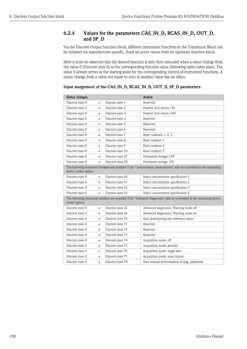
6 Discrete Output function block Device Functions Proline Promass 83 FOUNDATION Fieldbus
190 Endress+Hauser
6.2.4 Values for the parameters CAS_IN_D, RCAS_IN_D, OUT_D,
and SP_D
Via the Discrete Output function block, different instrument functions in the Transducer Block can
be initiated via manufacturer-specific, fixed set point values from an upstream function block.
Here it must be observed that the desired function is only then executed when a status change from
the value 0 (Discrete state 0) to the corresponding function value (following table) takes place. The
value 0 always serves as the starting point for the corresponding control of instrument functions. A
status change from a value not equal to zero to another value has no effect.
Input assignment of the CAS_IN_D, RCAS_IN_D, OUT_D, SP_D parameters
Status changes Action
Discrete state 0 → Discrete state 1 Reserved
Discrete state 0 → Discrete state 2 Positive zero return: ON
Discrete state 0 → Discrete state 3 Positive zero return: OFF
Discrete state 0 → Discrete state 4 Reserved
Discrete state 0 → Discrete state 5 Reserved
Discrete state 0 → Discrete state 6 Reserved
Discrete state 0 → Discrete state 7 Reset totalizers 1, 2, 3
Discrete state 0 → Discrete state 8 Reset totalizer 1
Discrete state 0 → Discrete state 9 Reset totalizer 2
Discrete state 0 → Discrete state 10 Reset totalizer 3
Discrete state 0 → Discrete state 27 Permanent storage: OFF
Discrete state 0 → Discrete state 28 Permanent storage: ON
The following measured variables are available if the "Concentration measurement" add-on is installed in the measuring
device (order option)
Discrete state 0 → Discrete state 60 Select concentration specification 1
Discrete state 0 → Discrete state 61 Select concentration specification 2
Discrete state 0 → Discrete state 62 Select concentration specification 3
Discrete state 0 → Discrete state 63 Select concentration specification 4
The following measured variables are available if the "Advanced diagnostics" add-on is installed in the measuring device
(order option)
Discrete state 0 → Discrete state 25 Advanced diagnostics: Warning mode off
Discrete state 0 → Discrete state 26 Advanced diagnostics: Warning mode on
Discrete state 0 → Discrete state 70 Start determining user reference status
Discrete state 0 → Discrete state 71 Reserved
Discrete state 0 → Discrete state 72 Reserved
Discrete state 0 → Discrete state 73 Reserved
Discrete state 0 → Discrete state 74 Acquisition mode: off
Discrete state 0 → Discrete state 75 Acquisition mode: periodic
Discrete state 0 → Discrete state 76 Acquisition mode: single shot
Discrete state 0 → Discrete state 77 Acquisition mode: reset history
Discrete state 0 → Discrete state 78 Start manual determination of diag. parameter

Device Functions Proline Promass 83 FOUNDATION Fieldbus 6 Discrete Output function block
Endress+Hauser 191
Example for controlling positive zero return via the Discrete Output function block.
The following example shows how positive zero return can be activated or deactivated via the
Discrete Output function block during a cleaning procedure.
1. In the first step, the connection between the Discrete Output function block and the
Transducer Block must be established. Here, the value 16 must be assigned to the parameter
CHANNEL in the Discrete Output function block.
→ Parameter CHANNEL → 16 (= Discrete Output function block)
2. In the CAS operating mode, the Discrete Output function block processes the set point value
specified at the input CAS_IN_D by the upstream function block and transfers it to the
Transducer Block.
Activating positive zero return
With a starting value of 0 (Discrete state 0), positive zero return is activated by a status change
from 0 to 2 at input CAS_IN_D.
Deactivating the positive zero return
Positive zero return can only then be deactivated when the input value at CAS_IN_D has first
been set to output value 0 (Discrete state 0). Only then can positive zero return be deactivated
through a status change from 0 to 2 at input CAS_IN_D.

7 Additional function blocks Device Functions Proline Promass 83 FOUNDATION Fieldbus
192 Endress+Hauser
7 Additional function blocks
! Note!
Additional function blocks such as the PID, Arithmetic, Input Selector, Signal Characterizer and
Integrator function block are described in the "FOUNDATION Fieldbus Overview" (BA013S)
Operating Instructions (available at: → www.endress.com → download).

Device Functions Proline Promass 83 FOUNDATION Fieldbus 8 Factory settings
Endress+Hauser 193
8 Factory settings
8.1 SI units (not for USA and Canada)
8.1.1 Low flow cut off, full scale value, pulse value
8.1.2 Language
Nominal diameter Low flow cut off Full scale value
[mm] (approx. v = 0.04 m/s) (approx. v = 2.0 m/s)
1 0.08 kg/h 4 kg/h
2 0.40 kg/h 20 kg/h
4 1.80 kg/h 90 kg/h
8 8.00 kg/h 400 kg/h
15 26.00 kg/h 1300 kg/h
15 FB 72.00 kg/h 3600 kg/h
25 72.00 kg/h 3600 kg/h
25 FB 180.00 kg/h 9000 kg/h
40 180.00 kg/h 9000 kg/h
40 FB 300.00 kg/h 15000 kg/h
50 300.00 kg/h 15000 kg/h
50 FB 720.00 kg/h 36000 kg/h
80 720.00 kg/h 36000 kg/h
100 1200.00 kg/h 60000 kg/h
150 2600.00 kg/h 130000 kg/h
250 7200.00 kg/h 360000 kg/h
FB = Full bore versions of Promass I
Country Language
Australia English
Belgium English
China Chinese
Denmark English
Germany Deutsch
England English
Finland Suomi
France Francais
Netherlands Nederlands
Hong Kong English
India English
Indonesia Bahasa Indonesia
Instruments International English
Italy Italiano
Japan Japanese
Malaysia English
Norway Norsk
Poland Polish
Portugal Portuguese
Austria Deutsch
Russia Russian
Sweden Svenska
Switzerland Deutsch
Singapore English
Spain Espanol
South Africa English
Thailand English
Czech Republic Czech
Hungary English

8 Factory settings Device Functions Proline Promass 83 FOUNDATION Fieldbus
194 Endress+Hauser
8.1.3 Density, length, temperature
8.2 US units (only for USA and Canada)
8.2.1 Low flow cut off, full scale value, pulse value
8.2.2 Language, density, length, temperature
Unit
Density kg/l
Length mm
Temperature ° C
Nominal diameter Low flow cut off Full scale value
[mm] (approx. v = 0.04 m/s) (approx. v = 2.0 m/s)
1 0.003 lb/min 0.15 lb/min
2 0.015 lb/min 0.75 lb/min
4 0.066 lb/min 3.30 lb/min
8 0.300 lb/min 15.00 lb/min
15 1.000 lb/min 50.00 lb/min
15 FB 2.600 lb/min 130.00 lb/min
25 2.600 lb/min 130.00 lb/min
25 FB 6.600 lb/min 330.00 lb/min
40 6.600 lb/min 330.00 lb/min
40 FB 11.000 lb/min 550.00 lb/min
50 11.000 lb/min 550.00 lb/min
50 FB 26.000 lb/min 1300.00 lb/min
80 26.000 lb/min 1300.00 lb/min
100 44.000 lb/min 2200.00 lb/min
150 95.000 lb/min 4800.00 lb/min
250 260.000 lb/min 13000.00 lb/min
FB = Full bore versions of Promass I
Unit
Language English
Density g/cc
Length INCH
Temperature °F

Device Functions Proline Promass 83 FOUNDATION Fieldbus 9 Index FOUNDATION Fieldbus
Endress+Hauser 195
9 Index FOUNDATION Fieldbus
AAccess
Transducer Block . . . . . . . . . . . . . . . . . . . . . . . . . . . 113
Access - Code
"Flow" Transducer Block . . . . . . . . . . . . . 114, 131, 134
"Totalizer" Transducer Block . . . . . 151, 155, 166, 169
Access - Code Counter
"Flow" Transducer Block . . . . . . . . . . . . . . . . . . . . . . 134
Access - Def.Private Code
"Display" Transducer Block . . . . . . . . . . . . . . . . . . . . 135
Access - Status
"Flow" Transducer Block . . . . . . . . . . . . . 114, 131, 134
"Totalizer" Transducer Block . . . . . 151, 155, 166, 169
Add. Line - ...
"Display" Transducer Block . . . . . . . . . . . . . . . 141, 142
Alarm delay . . . . . . . . . . . . . . . . . . . . . . . . . . . . . . . . . . 132
Alarm detection
AI function block . . . . . . . . . . . . . . . . . . . . . . . . . . . 186
Resource Block . . . . . . . . . . . . . . . . . . . . . . . . . . . . . 107
Transducer Block . . . . . . . . . . . . . . . . . . . . . . . . . . . 112
Alarm processing
AI function block . . . . . . . . . . . . . . . . . . . . . . . . . . . 186
Resource Block . . . . . . . . . . . . . . . . . . . . . . . . . . . . . 107
Transducer Block . . . . . . . . . . . . . . . . . . . . . . . . . . . 112
Amp. - HW Identification
Resource Block . . . . . . . . . . . . . . . . . . . . . . . . . . . . . 108
Amp. - HW Rev.Number
Resource Block . . . . . . . . . . . . . . . . . . . . . . . . . . . . . 108
Amp. - Language Group
Resource Block . . . . . . . . . . . . . . . . . . . . . . . . . . . . . 108
Amp. - Prod.Number
Resource Block . . . . . . . . . . . . . . . . . . . . . . . . . . . . . 108
Amp. - SW Identification
Resource Block . . . . . . . . . . . . . . . . . . . . . . . . . . . . . 108
Amp. - SW Rev.No. T-DAT
Resource Block . . . . . . . . . . . . . . . . . . . . . . . . . . . . . 108
Amp. - SW Rev.Number
Resource Block . . . . . . . . . . . . . . . . . . . . . . . . . . . . . 108
Amp. Device Type
"Totalizer" Transducer Block . . . . . . . . . . . . . . . . . . . 168
Amplifier
Hardware identification number . . . . . . . . . . . . . . . . 108
Hardware revision number . . . . . . . . . . . . . . . . . . . . 108
Language Group . . . . . . . . . . . . . . . . . . . . . . . . . . . . 108
Production number . . . . . . . . . . . . . . . . . . . . . . . . . . 108
Software identification number . . . . . . . . . . . . . . . . . 108
Software revision number . . . . . . . . . . . . . . . . . . . . . 108
Assign
DO function block . . . . . . . . . . . . . . . . . . . . . . . . . . 189
BBacklight
Display . . . . . . . . . . . . . . . . . . . . . . . . . . . . . . . . . . . 136
Block model . . . . . . . . . . . . . . . . . . . . . . . . . . . . . . . . . . 104
Block output values
Transducer Block . . . . . . . . . . . . . . . . . . . . . . . . . . . 111
Block status
Resource Block . . . . . . . . . . . . . . . . . . . . . . . . . . . . . 106
CCode
Input counter . . . . . . . . . . . . . . . . . . . . . . . . . . . . . . . 25
Code entry
See Access - Code
Code entry, personal private code . . . . . . . . . . . . . . . . . . 135
Config. - Backlight
"Display" Transducer Block . . . . . . . . . . . . . . . . . . . . 136
Config. - Contrast LCD
"Display" Transducer Block . . . . . . . . . . . . . . . . . . . . 136
Config. - Display Damping
"Display" Transducer Block . . . . . . . . . . . . . . . . . . . . 136
Config. - Language
"Display" Transducer Block . . . . . . . . . . . . . . . . . . . . 135
DDamping
Display . . . . . . . . . . . . . . . . . . . . . . . . . . . . . . . . . . . 136
Device Software
Resource Block . . . . . . . . . . . . . . . . . . . . . . . . . . . . . 108
Diag. - Act. Sys. Condition
"Diagnosis" Transducer Block . . . . . . . . . . . . . . . . . . 131
Diag. - Prev. Sys. Condition
"Diagnosis" Transducer Block . . . . . . . . . . . . . . . . . . 131
Diagnosis
AI function block . . . . . . . . . . . . . . . . . . . . . . . . . . . 185
Transducer Block . . . . . . . . . . . . . . . . . . . . . . . . . . . 113
Discrete Output function block . . . . . . . . . . . . . . . . . . . . 188
Display
Backlight . . . . . . . . . . . . . . . . . . . . . . . . . . . . . . . . . . 136
Configuration
Additional line . . . . . . . . . . . . . . . . . . . . . . 141, 142
Information line . . . . . . . . . . . . . . . . . . . . . 146, 147
Main line . . . . . . . . . . . . . . . . . . . . . . . . . . 137, 138
Contrast . . . . . . . . . . . . . . . . . . . . . . . . . . . . . . . . . . 136
Damping . . . . . . . . . . . . . . . . . . . . . . . . . . . . . . . . . . 136
Density value, fixed . . . . . . . . . . . . . . . . . . . . . . . . . . 116
Format (number of decimal places displayed)
Additional line . . . . . . . . . . . . . . . . . . . . . . . . . . . 142
Information line . . . . . . . . . . . . . . . . . . . . . . . . . . 147
Main line . . . . . . . . . . . . . . . . . . . . . . . . . . . . . . . 138
Language setting . . . . . . . . . . . . . . . . . . . . . . . . . . . . 135
Mass flow, calculated . . . . . . . . . . . . . . . . . . . . . . . . 114
Measuring device operating duration . . . . . . . . . . . . . 132
Test function . . . . . . . . . . . . . . . . . . . . . . . . . . . . . . . 136
Volume flow . . . . . . . . . . . . . . . . . . . . . . . . . . . . . . . 115
EEmpty pipe detection
EPD activation . . . . . . . . . . . . . . . . . . . . . . . . . . . . . . 55
Error messages
See System condition

9 Index FOUNDATION Fieldbus Device Functions Proline Promass 83 FOUNDATION Fieldbus
196 Endress+Hauser
FFault message
See Operating Instructions for
Proline Promass 83 FOUNDATION Fieldbus (BA065D)
Function blocks . . . . . . . . . . . . . . . . . . . . . . . . . . . . . . . 180
II/O - HW Identification
Resource Block . . . . . . . . . . . . . . . . . . . . . . . . . . . . 108
I/O - HW Rev. Number
Resource Block . . . . . . . . . . . . . . . . . . . . . . . . . . . . 108
I/O - Prod.Number
Resource Block . . . . . . . . . . . . . . . . . . . . . . . . . . . . 108
I/O - SW Identification
Resource Block . . . . . . . . . . . . . . . . . . . . . . . . . . . . 108
I/O - SW Rev. Number
Resource Block . . . . . . . . . . . . . . . . . . . . . . . . . . . . 108
I/O - Type
Resource Block . . . . . . . . . . . . . . . . . . . . . . . . . . . . 108
I/O Module
Device software . . . . . . . . . . . . . . . . . . . . . . . . . . . . 108
Hardware identification number . . . . . . . . . . . . . . . . 108
Hardware revision number . . . . . . . . . . . . . . . . . . . . 108
Production number . . . . . . . . . . . . . . . . . . . . . . . . . 108
Software identification number . . . . . . . . . . . . . . . . . 108
Software revision number . . . . . . . . . . . . . . . . . . . . 108
Identification number
Amplifier hardware . . . . . . . . . . . . . . . . . . . . . . . . . 108
Amplifier software . . . . . . . . . . . . . . . . . . . . . . . . . . 108
I/O module hardware . . . . . . . . . . . . . . . . . . . . . . . 108
I/O module software . . . . . . . . . . . . . . . . . . . . . . . . 108
Info Line - ...
"Display" Transducer Block . . . . . . . . . . . . . . . 146, 147
Input counter . . . . . . . . . . . . . . . . . . . . . . . . . . . . . . . . . 25
LLanguage group amplifier . . . . . . . . . . . . . . . . . . . . . . . . 108
Limit values
AI function block . . . . . . . . . . . . . . . . . . . . . . . . . . . 186
MMain Line - ...
"Display" Transducer Block . . . . . . . . . . . . . . . 137, 138
NNotice message
See Operating Instructions for
Proline Promass 83 FOUNDATION Fieldbus (BA065D)
OOperating duration, measuring device . . . . . . . . . . . . . . 132
Operating mode
AI function block . . . . . . . . . . . . . . . . . . . . . . . . . . . 183
DO function block . . . . . . . . . . . . . . . . . . . . . . . . . . 189
Resource Block . . . . . . . . . . . . . . . . . . . . . . . . . . . . 106
Transducer Block . . . . . . . . . . . . . . . . . . . . . . . . . . . 112
Operation - Test Display
"Display" Transducer Block . . . . . . . . . . . . . . . . . . . 136
PParameters
Resource Block . . . . . . . . . . . . . . . . . . . . . . . . . . . . . 108
Pressure shock suppression . . . . . . . . . . . . . . . . . . 119, 120
Process - Pressure Shock Suppression
"Flow" Transducer Block . . . . . . . . . . . . . . . . . 119, 120
Process variable assignment
AI function block . . . . . . . . . . . . . . . . . . . . . . . . . . . 183
Production number
Amplifier . . . . . . . . . . . . . . . . . . . . . . . . . . . . . . . . . 108
I/O Module . . . . . . . . . . . . . . . . . . . . . . . . . . . . . . . 108
RRescaling
AI function block . . . . . . . . . . . . . . . . . . . . . . . . . . . 185
Resource . . . . . . . . . . . . . . . . . . . . . . . . . . . . . . . . . . . . 106
Resource Block . . . . . . . . . . . . . . . . . . . . . . . . . . . . . . . 106
Resource Block parameters . . . . . . . . . . . . . . . . . . . . . . 106
Revision number
Amplifier hardware . . . . . . . . . . . . . . . . . . . . . . . . . 108
Amplifier software . . . . . . . . . . . . . . . . . . . . . . . . . . 108
SSafety behavior
DO function block . . . . . . . . . . . . . . . . . . . . . . . . . . 189
Select units ("Flow" Transducer Block)
Density value, fixed . . . . . . . . . . . . . . . . . . . . . 116, 117
Mass flow . . . . . . . . . . . . . . . . . . . . . . . . . . . . . . . . 114
Volume flow . . . . . . . . . . . . . . . . . . . . . . . . . . . . . . 115
Sensor
Serial number . . . . . . . . . . . . . . . . . . . . . . . . . . . . . . 108
Sensor -
Serial Number
Resource Block . . . . . . . . . . . . . . . . . . . . . . . . . . . . . 108
Serial number sensor . . . . . . . . . . . . . . . . . . . . . . . . . . . 108
Set points
DO function block . . . . . . . . . . . . . . . . . . . . . . . . . . 190
Signal processing
AI function block . . . . . . . . . . . . . . . . . . . . . . . . . . . 181
DO function block . . . . . . . . . . . . . . . . . . . . . . . . . . 188
Transducer Block . . . . . . . . . . . . . . . . . . . . . . . . . . . 110
Simulation
AI function block . . . . . . . . . . . . . . . . . . . . . . . . . . . 185
Measured value display . . . . . . . . . . . . . . . . . . . . . . 130
Resource Block . . . . . . . . . . . . . . . . . . . . . . . . . . . . . 106
Totalizer failsafe mode . . . . . . . . . . . . . . . . . . . . . . . 132
Simulation - Unit
"Flow" Transducer Block . . . . . . . . . . . . . . . . . . . . . 130
Status OUT
AI function block . . . . . . . . . . . . . . . . . . . . . . . . . . . 184
Store permanently . . . . . . . . . . . . . . . . . . . . . . . . . . . . . 121
Sys. - Alarm Delay
"Diagnosis" Transducer Block . . . . . . . . . . . . . . . . . . 132
Sys. - Operation Time
"Diagnosis" Transducer Block . . . . . . . . . . . . . . . . . . 132
Sys. - Permanent Storage
"Flow" Transducer Block . . . . . . . . . . . . . . . . . . . . . 121
Sys. - Reset
"Diagnosis" Transducer Block . . . . . . . . . . . . . . . . . . 132

Device Functions Proline Promass 83 FOUNDATION Fieldbus 9 Index FOUNDATION Fieldbus
Endress+Hauser 197
Sys. - Sim. Failsafe Mode
"Diagnosis" Transducer Block . . . . . . . . . . . . . . . . . . 132
Sys. - T-DAT Save/Load
"Diagnosis" Transducer Block . . . . . . . . . . . . . . . . . . 133
Sys. - Time Since Reset
"Diagnosis" Transducer Block . . . . . . . . . . . . . . . . . . 132
System condition
Actual . . . . . . . . . . . . . . . . . . . . . . . . . . . . . . . . . . . . 131
Previous (error history) . . . . . . . . . . . . . . . . . . . . . . . 131
System reset (without disconnecting main power) . . . . . . 132
System Unit - Corr.Volume Flow
"‘Flow" Transducer Block . . . . . . . . . . . . . . . . . . . . . 116
System Unit - Fixed Density
"Flow" Transducer Block . . . . . . . . . . . . . . . . . . . . . . 116
System Unit - Mass Flow
"Flow" Transducer Block . . . . . . . . . . . . . . . . . . . . . . 114
System Unit - Volume Flow
"Flow" Transducer Block . . . . . . . . . . . . . . . . . . . . . . 115
System Value - Corr.Volume Flow
"Flow" Transducer Block . . . . . . . . . . . . . . . . . . . . . . 115
System Value - Density
"Flow" Transducer Block . . . . . . . . . . . . . . . . . . . . . . 116
System Value - Mass Flow
"Flow" Transducer Block . . . . . . . . . . . . . . . . . . . . . . 114
System Value - Ref. Density
"Flow" Transducer Block . . . . . . . . . . . . . . . . . 116, 117
System Value - Volume Flow
"Flow" Transducer Block . . . . . . . . . . . . . . . . . . . . . . 115
TT-DAT
Amplifier software revision number . . . . . . . . . . . . . . 108
Loading/saving data . . . . . . . . . . . . . . . . . . . . . . . . . 133
Tot. - Failsafe All
"Totalizer" Transducer Block . . . . . . . . . . . . . . . . . . . 154
Tot. - Reset All
"Totalizer" Transducer Block . . . . . . . . . . . . . . . . . . . 154
Tot. 1 to 3 - Assign
"Totalizer" Transducer Block . . . . . . . . . . . . . . . . . . . 153
Tot. 1 to 3 - Mode
"Totalizer" Transducer Block . . . . . . . . . . . . . . . . . . . 153
Tot. 1 to 3 - Reset
"Totalizer" Transducer Block . . . . . . . . . . . . . . . . . . . 153
Tot. 1 to 3 - Sum
"Totalizer" Transducer Block . . . . . . . . . . . . . . . . . . . 152
Tot. 1 to 3 - Unit
"Totalizer" Transducer Block . . . . . . . . . . . . . . . . . . . 152
Totalizer
Define failsafe mode . . . . . . . . . . . . . . . . . . . . . . . . . 154
Reset (all) . . . . . . . . . . . . . . . . . . . . . . . . . . . . . . . . . 154
Simulation failsafe mode . . . . . . . . . . . . . . . . . . . . . . 132
Totalizer 1
Reset . . . . . . . . . . . . . . . . . . . . . . . . . . . . . . . . . . . . . 153
Totalizer 1 to 3
Assignment (volume, mass) . . . . . . . . . . . . . . . . . . . . 153
Balancing mode . . . . . . . . . . . . . . . . . . . . . . . . . . . . . 153
Display value . . . . . . . . . . . . . . . . . . . . . . . . . . . . . . . 152
Unit . . . . . . . . . . . . . . . . . . . . . . . . . . . . . . . . . . . . . 152
Transducer Block . . . . . . . . . . . . . . . . . . . . . . . . . . . . . . 109
Type of linearization
AI function block . . . . . . . . . . . . . . . . . . . . . . . . . . . 183
UUnits
AI function block . . . . . . . . . . . . . . . . . . . . . . . . . . . 184
VVisc. - Dyn.Viscosity
"Totalizer" Transducer Block . . . . . . . . . . . . . . . . . . . 166
Visc. - Kin.Viscosity
"Totalizer" Transducer Block . . . . . . . . . . . . . . . . . . . 167
Visc. - Ref.Temperature
"Totalizer" Transducer Block . . . . . . . . . . . . . . . . . . . 167
Visc. - Temp.Comp.Dyn.Viscosity
"Totalizer" Transducer Block . . . . . . . . . . . . . . . . . . . 167
Visc. - Temp.Comp.Model
"Totalizer" Transducer Block . . . . . . . . . . . . . . . . . . . 167
Visc. - Temp.Kin.Viscosity
"Totalizer" Transducer Block . . . . . . . . . . . . . . . . . . . 167
Visc. - Unit Dyn.Viscosity
"Totalizer" Transducer Block . . . . . . . . . . . . . . . . . . . 167
Visc. - Unit Kin.Viscosity
"Totalizer" Transducer Block . . . . . . . . . . . . . . . . . . . 167
Visc. - X1
"Totalizer" Transducer Block . . . . . . . . . . . . . . . . . . . 168
Visc. - X2
"Totalizer" Transducer Block . . . . . . . . . . . . . . . . . . . 168
Visc. - Y1
"Totalizer" Transducer Block . . . . . . . . . . . . . . . . . . . 168
WWrite protection
Resource Block . . . . . . . . . . . . . . . . . . . . . . . . . . . . . 106


www.endress.com/worldwide
BA066D/06/en/12.06
71035083
FM+SGML 6.0