Special Documentation Proline Promass 80, 83
15
Products Solutions Services SD00077D/06/EN/14.14 71272498 Special Documentation Proline Promass 80, 83 Functional safety manual Coriolis mass flow measuring system with 4–20 mA output signal Application Monitoring of maximum and/or minimum flow or density in systems which are required to comply with particular safety system require- ments as per IEC/EN 61508. The measuring device fulfils the requirements concerning: • Functional safety as per IEC/EN 61508 • Explosion protection (depending on the version) • Electromagnetic compatibility as per EN 61326-3-2 and NAMUR recommendation NE 21 • Electrical safety as per IEC/EN 61010-1 Your benefits • For flow monitoring (Min., Max., range) up to SIL 2 (single-chan- nel architecture) or SIL 3 (multichannel architecture with homo- geneous redundancy). Independently assessed and certified by TÜV as per IEC/ EN 61508 • Alternatively, suitable for density monitoring also (Min., Max., range) • Continuous measurement • Measurement is virtually independent of product properties • Permanent self-monitoring • Easy installation and commissioning • Proof test possible without removal of the measuring device
Transcript of Special Documentation Proline Promass 80, 83

Products Solutions ServicesSD00077D/06/EN/14.1471272498
Special DocumentationProline Promass 80, 83Functional safety manual
Coriolis mass flow measuring systemwith 4–20 mA output signalApplication
Monitoring of maximum and/or minimum flow or density in systems
which are required to comply with particular safety system require-
ments as per IEC/EN 61508.
The measuring device fulfils the requirements concerning:
• Functional safety as per IEC/EN 61508
• Explosion protection (depending on the version)
• Electromagnetic compatibility as per
EN 61326-3-2 and NAMUR recommendation NE 21
• Electrical safety as per IEC/EN 61010-1
Your benefits
• For flow monitoring (Min., Max., range) up to SIL 2 (single-chan-
nel architecture) or SIL 3 (multichannel architecture with homo-
geneous redundancy).
Independently assessed and certified by TÜV as per IEC/
EN 61508
• Alternatively, suitable for density monitoring also (Min., Max.,
range)
• Continuous measurement
• Measurement is virtually independent of product properties
• Permanent self-monitoring
• Easy installation and commissioning
• Proof test possible without removal of the measuring device

Proline Promass 80, 83
2 Endress+Hauser
Table of contents
SIL Certificate. . . . . . . . . . . . . . . . . . . . . . . . . . . . . . . . . . .3
Introduction . . . . . . . . . . . . . . . . . . . . . . . . . . . . . . . . . . . .4Depiction of a safety system (protection function) . . . . . . . . . . 4
Measuring system layout with Promass 80/83 . . . . . .5System components . . . . . . . . . . . . . . . . . . . . . . . . . . . . . . . . . . . 5Safety function data . . . . . . . . . . . . . . . . . . . . . . . . . . . . . . . . . . . 5Supplementary device documentation . . . . . . . . . . . . . . . . . . . . 5
Settings and installation instructions . . . . . . . . . . . . . .6Installation instructions . . . . . . . . . . . . . . . . . . . . . . . . . . . . . . . . 6Setting instructions . . . . . . . . . . . . . . . . . . . . . . . . . . . . . . . . . . . . 6Monitoring options . . . . . . . . . . . . . . . . . . . . . . . . . . . . . . . . . . . . 7Locking . . . . . . . . . . . . . . . . . . . . . . . . . . . . . . . . . . . . . . . . . . . . . . 8Setting instructions for evaluation unit . . . . . . . . . . . . . . . . . . . 8Response in operation and failure . . . . . . . . . . . . . . . . . . . . . . . . 8Information on the useful lifetime of electric components . . . 8
Proof test . . . . . . . . . . . . . . . . . . . . . . . . . . . . . . . . . . . . . .9Proof test of the measuring system . . . . . . . . . . . . . . . . . . . . . . . 9
Appendix (safety-related characteristic values) . . . 11Introductory comments . . . . . . . . . . . . . . . . . . . . . . . . . . . . . . . . 11Categories . . . . . . . . . . . . . . . . . . . . . . . . . . . . . . . . . . . . . . . . . . . 13

Proline Promass 80, 83
Endress+Hauser 3
SIL Certificate
A0009782

Proline Promass 80, 83
4 Endress+Hauser
Introduction
Depiction of a safety system
(protection function)
The following tables define the achievable Safety Integrity Level (SIL) or the requirements regarding the "Average Probability of Failure on Demand" (PFDAVG), the "Hardware Fault Tolerance" (HFT) and the "Safe Failure Fraction" (SFF) of the safety system. The specific values for the Promass measuring system can be found in the tables in the appendix.
In general, the following permitted failure probability of the complete safety function applies, depending on the
SIL for systems which must react on demand - e.g. a defined max. flow exceeded - (Source: IEC 61508, Part 1):
The following table shows the achievable SIL as a function of the safe failure fraction and the hardware fault
tolerance of the complete safety system for type B systems (complex components, for definition see IEC 61508,
Part 2):
The measuring device can be used in safety relevant SIL 2 loop.
Additionally the measuring device can be used up to SIL 3 loop in a redundant structure (e.g. 1002 or 2003)
! Note!
General information on functional safety (SIL) is available at:
www.endress.com/SIL and in Competence Brochure CP002Z "Functional Safety in the Process Industry - Risk
Reduction with Safety Instrumented Systems" (available in the download section of the Endress+Hauser web-
site: www.endress.com Download Document code: CP002Z).
SIL PFDAVG
4 10–5 to <10–4
3 10–4 to < 10–3
2 10–3 to < 10–2
1 10–2 to < 10–1
SFF HFT
0 1 (0)1) 2 (1)1)
< 60% Not permitted SIL 1 SIL 2
60 % to < 90 % SIL 1 SIL 2 SIL 3
90 % to < 99 % SIL 2 SIL 3
99 % SIL 3
1) In accordance with IEC 61511-1 (section 11.4.41 ), the HFT can be reduced by one (values in brackets)
if the devices used meet the following conditions:
- The device is proven in use
- Only process-relevant parameters can be changed at the device (e.g. measuring range, … )
- Changing the process-relevant parameters is protected (e.g. password, jumper, … )
- The function requires less than SIL 4
The Promass measuring system meets these conditions.

Proline Promass 80, 83
Endress+Hauser 5
Measuring system layout with Promass 80/83
System components
A0015443
System components
1 Pump
2 Measuring device
3 Valve
4 Automation system
An analog signal (4–20 mA) proportional to the flow rate or the density is generated in the transmitter. This is
sent to a downstream automation system where it is monitored to determine whether it falls below or exceeds
a specified limit value.
! Note!
• The safety-related signal is the 4 to 20 mA analog output signal of the measuring device. All safety functions
refer exclusively to current output 1.
• The measuring device must be protected against unauthorized access see "Locking" section ( ä 8).
• The application program in the safety automation system is designed in such a way that "fail high" and "fail
low" failures are detected by the safety function regardless of the effect (safe or dangerous).
• If communication also takes place via the HART protocol in the Promass 83 measuring device, HART write
protection must be activated see the "Locking" section ( ä 8).
The characteristic values determined (see appendix) apply only to the current output (4 to 20 mA) of the fol-
lowing versions:
• Promass 80***–***********(*)
(*) = Order option for inputs/outputs: A / D / S / T / 8
• Promass 83***–***********(*)
(*) = Order option for inputs/outputs: A / B / C / D / E / L / M / R / S / T / U / W / 0 / 2 / 3 / 4 / 5 / 6
Safety function data The mandatory settings and safety function data emanate from the section "Settings and installation instruc-
tions" ( ä 6) and the appendix ( ä 11). The measuring system's response time is 2 s. The monitoring
function's alarm delay does not start until after this.
! Note!
8 hours is set for the time between when the failure occurs and the failure is eliminated (MTTR).
Supplementary device docu-
mentation
The following documentation must be available for the measuring system:
This document also includes information on application limits and ambient conditions as well as the functional
specifications of the current output.
For devices with an explosion protection approval, the corresponding Safety Instructions (XA) or Control Draw-
ings (ZD) must also be observed.
1 2 3
4
Device type Operating Instructions Description of the device functions
Promass 80 BA00057D/06 BA00058D/06
Promass 83 BA00059D/06 BA00060D/06
Proline Promass 80, 83
6 Endress+Hauser
Settings and installation instructions
Installation instructions Instructions for the correct installation of the measuring device can be found in the Operating Instructions (BA)
supplied see "Further applicable device documentation" ( ä 5).
Suitability of the measuring device
Carefully select the nominal diameter of the measuring device in accordance with the application's expected
flow rates. The maximum flow rate during operation must not exceed the specified maximum value for the
sensor. In safety-related applications, it is also recommended to select a limit value for monitoring the minimum
flow rate that is not smaller than 5 % of the specified maximum value of the sensor.
The measuring device must be used correctly for the specific application, taking into account the medium
properties and ambient conditions. Carefully follow instructions pertaining to critical process situations and
installation conditions from the device documentation.
Please pay particular attention to the following:
• It is very important to avoid the occurrence of air, gas bubble formation or two-phase mixtures in the mea-
suring pipe as they can lead to increased measurement errors.
• For liquids that readily boil and in the case of suction conveying: Ensure that the vapor pressure is not under-
shot and that the liquid does not start to boil.
• Please ensure that there is never any outgassing of the gases naturally contained in many liquids. Such effects
can be prevented when system pressure is sufficiently high.
• Ensure that no cavitation occurs as it can affect the vibration and operating life of the measuring pipes.
• In principle, the device supports the mass flow of gaseous media under pressure. This application is not rec-
ommended for safety-related flow monitoring.
• Avoid applications that cause buildup or corrosion in the measuring pipe.
In general, there are no specific requirements for single-phase, liquid media with properties similar to those of
water.
! Note!
Please contact your Endress+Hauser sales office for further information.
Setting instructions The measuring device can be configured in various ways in process control protection systems:
• Via onsite operation (LCD display)
• Via HART handheld terminal DXR 375
• Via PC (remote operation) using service and configuration software (e.g. "FieldCare")
The tools mentioned can also be used to retrieve information on the software and hardware revision of the
device. ä 5Further instructions on the settings can be found in the corresponding Operating Instructions
see "Supplementary device documentation" ( ä 5).

Proline Promass 80, 83
Endress+Hauser 7
Monitoring options The measuring device can be used in protective systems to monitor (Min., Max. and range) the following:
• Mass flow
• Volume flow
• Density
! Note!
The device must be correctly installed to guarantee safe operation.
A0015277
Monitoring options in protective systems
A Min. alarm
B Max. alarm
C Range monitoring
= Safety function activated
= Permitted operating status
The following table shows the settings which are necessary to use the measuring device in a safety-related
application. The settings refer to the 4 to 20 mA output value of the current output which corresponds to the
flow value.
A detailed description of the functions of the device can be found in the appropriate "Description of Device
Functions" see "Further applicable device documentation" ( ä 5).
4 Min. [mA]Max. 20
A
B
C
Group Name of function in the group Allowed setting when Promass is used for a safety function
CURRENT OUTPUT ASSIGN CURRENT OUTPUT – Mass flow
– Volume flow
– Density
CURRENT OUTPUT CURRENT SPAN – 4–20 mA (………):
All settings with a current output configuration to
4-20 mA.
– 0…20 mA:
Setting is not allowed.
Promass 80All configuration options 4 to 20 mA with HART
communication are not permitted.
Promass 83All configuration options 4 to 20 mA with HART
communication are only permitted if HART write
protection is activated ( ä 8, "Locking" section)
CURRENT OUTPUT FAILSAFE MODE – Min. current
– Max. current
CURRENT OUTPUT SIMULATION CURRENT OFF
SYSTEM PARAMETER POSITIVE ZERO RETURN OFF
SUPERVISION ASSIGN SYSTEM ERROR OFF
(the assignment of information messages and fault
messages may not be changed)
SUPERVISION ALARM DELAY 0…20 s
SIMULATION SYSTEM SIMULATION FAILSAFE MODE OFF
SIMULATION SYSTEM SIMULATION MEASURAND OFF

Proline Promass 80, 83
8 Endress+Hauser
Locking In order to protect the process relevant parameters against change, the software has to be locked.
This is done via a code set by the customer.
Promass 83:When using HART communication, the HART write protection must be activated. This can be done with the
aid of a jumper on the I/O board. Please refer to the appropriate Operating Instructions for the correct proce-
dure to activate the HART write protection see "Further applicable device documentation" ( ä 5).
Setting instructions for evalua-
tion unit
The determined limit value (mA value corresponding to chosen max. and/or min.) must be entered at the sub-
sequent limit contactor (automation system). For all adjustment and setting procedures, please refer to the rel-
evant Operating Instructions see "Further applicable device documentation" ( ä 5).
Response in operation and
failure
The response in operation and failures is described in the Operating Instructions of the device
see "Further applicable device documentation" ( ä 5).
! Note!
• Repair: The repair of the devices must principally be performed by Endress+Hauser.
Is the repair carried out by other people, the safety related functions can no longer be assured.
Exception: The replacement of modular components by original spare parts is permitted by qualified per-
sonnel of the customer, if trained by Endress+Hauser for this purpose.
• A failure of a SIL marked Endress+Hauser product, which was operated in a safety instrumented system,
shall be reported to [email protected] including product type, serial number and description of the failure.
Device failures must be reported to the manufacturer. The user provides a detailed statement to the manu-
facturer describing the failure and any possible effects. There is also information flow as to whether this is a
dangerous failure or a failure which cannot be detected directly.
• In the event of failure of a SIL marked Endress+Hauser device, which has been operated in a safety function,
the "Declaration of Contamination and Cleaning" with the corresponding note "Used as SIL device in
protection system" must be enclosed when the defective device is returned.
Information on the useful life-
time of electric components
The established failure rates of electrical components apply within the useful lifetime as per
IEC/EN 61508-2, section 7.4.7.4, note 3.
! Note!
The manufacturer and plant owner/operator must take appropriate measures to achieve a longer service life as
per DIN EN 61508-2, note NA4.
Software lock for local programming
Function DEFINE PRIVATE
CODE
Freely choosable code number (except for 0)

Proline Promass 80, 83
Endress+Hauser 9
Proof test
Proof test of the measuring
system
Check the operativeness of safety functions at appropriate intervals. The operator must determine the time interval and take this into account when determining the probability of failure PFDavg of the sensor system.
! Note!
In a single-channel architecture, the maximum value of PFDavg depends on the diagnostic coverage of the proof test (PTC = Proof Test Coverage) and the intended lifetime (LT = Lifetime) in accordance with the following formula:
A0015275
The functional test must be carried out in such a way that it verifies correct operation of the safety device in
conjunction with all of the other components. Each test must be fully documented.
The accuracy of the measured value must first be checked in order to test the safety function (Min., Max.,
range). This involves approaching the configured limit values upon which the safety function (including actu-
ator) should be activated. Checking the accuracy of the measured values is sufficient in order to test the "Range"
safety function.
During the proof test, alternative monitoring measures must be taken to ensure process safety.
A proof test of the device can be performed in the following steps:
1. Checking the digital measured valueOne of the following tests must be carried out depending on the measured variable to be monitored and the available equipment:a. Test sequence A – Checking the digital measured value with a calibration rig
Mass flow, volume flow or density
The measuring device is recalibrated using a calibration rig that is certified in accordance with ISO
17025. This can be done on an installed device using a mobile calibration rig or using factory calibra-
tion if the device has been disassembled. The amount of deviation between the measured flow rate
or density and the set point must not exceed the maximum measured error specified in the Operating
Instructions.
! Note!
Please contact your Endress+Hauser sales office for further information on standard methods for on-
site calibration of flowmeters.
b. Test sequence B – Checking the digital measured value using the installed totalizer
Mass flow
A measuring vessel is filled with the medium at a flow rate which corresponds to the limit value to
be monitored. A calibrated scales is used to determine the change in the overall mass in the measuring
vessel before and after filling which is then compared with the totalizer installed in the device. The
amount of deviation must not exceed the maximum measured error specified in the Operating
Instructions. For range monitoring, this test must be carried out separately for the upper and lower
limit value.
Volume flow
A calibrated measuring vessel is filled with the medium at a flow rate which corresponds to the limit
value to be monitored. The change in the volume in the measuring vessel is read off before and after
filling and compared with the totalizer installed in the measuring device. The amount of deviation
must not exceed the maximum measured error specified in the Operating Instructions. For range
monitoring, this test must be carried out in 5 stages between the upper and lower limit value.
c. Test sequence C – Checking the digital measured value using liquids of known density
Density
The device's measuring pipes are filled with at least two different liquids of known density one after
the other. The digital density measured value determined in each case is compared with the actual
density of the measurement liquid. The amount of deviation must not exceed the maximum mea-
sured error specified in the Operating Instructions.
T ( – PTC LT�avg duPFD i[PTC/2 ]. . + .≈ 1 )/2
Proline Promass 80, 83
10 Endress+Hauser
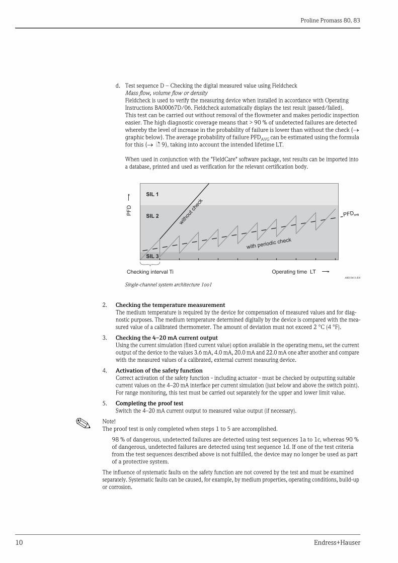
d. Test sequence D – Checking the digital measured value using Fieldcheck
Mass flow, volume flow or density
Fieldcheck is used to verify the measuring device when installed in accordance with Operating
Instructions BA00067D/06. Fieldcheck automatically displays the test result (passed/failed).
This test can be carried out without removal of the flowmeter and makes periodic inspection easier. The high diagnostic coverage means that > 90 % of undetected failures are detected whereby the level of increase in the probability of failure is lower than without the check (graphic below). The average probability of failure PFDAVG can be estimated using the formula for this ( ä 9), taking into account the intended lifetime LT.
When used in conjunction with the "FieldCare" software package, test results can be imported into
a database, printed and used as verification for the relevant certification body.
A0015615-EN
Single-channel system architecture 1oo1
2. Checking the temperature measurementThe medium temperature is required by the device for compensation of measured values and for diag-
nostic purposes. The medium temperature determined digitally by the device is compared with the mea-
sured value of a calibrated thermometer. The amount of deviation must not exceed 2 °C (4 °F).
3. Checking the 4–20 mA current outputUsing the current simulation (fixed current value) option available in the operating menu, set the current
output of the device to the values 3.6 mA, 4.0 mA, 20.0 mA and 22.0 mA one after another and compare
with the measured values of a calibrated, external current measuring device.
4. Activation of the safety functionCorrect activation of the safety function - including actuator - must be checked by outputting suitable
current values on the 4–20 mA interface per current simulation (just below and above the switch point).
For range monitoring, this test must be carried out separately for the upper and lower limit value.
5. Completing the proof test
Switch the 4–20 mA current output to measured value output (if necessary).
! Note!
The proof test is only completed when steps 1 to 5 are accomplished.
98 % of dangerous, undetected failures are detected using test sequences 1a to 1c, whereas 90 % of dangerous, undetected failures are detected using test sequence 1d. If one of the test criteria from the test sequences described above is not fulfilled, the device may no longer be used as part of a protective system.
The influence of systematic faults on the safety function are not covered by the test and must be examined
separately. Systematic faults can be caused, for example, by medium properties, operating conditions, build-up
or corrosion.
PF
D
SIL 3
SIL 2
SIL 1
PFDavg
Operating time LT
with periodic check
with
out c
heck
Checking interval Ti

Proline Promass 80, 83
Endress+Hauser 11
Appendix (safety-related characteristic values)
Introductory comments Depending on the order code, Promass flow measuring systems are supplied with different signal inputs and
outputs. For the purposes of clarity, similar types of electronics modules are grouped into categories.
! Note!
• The safety-related characteristic values are described separately for each of these categories see sections
"Category 1-10". The tables provided in these category sections contain all the important characteristic val-
ues. The values apply to all possible applications:
• The failure rates indicated refer to the failure rates of Siemens Standard SN29500 at an ambient temperature
of +40 °C (+104 °F).
Measuring system / elec-
tronics
Product structure
Ex Outputs and inputs Category
ä 13
Promass 80
80 *** – ***********A – Curr. outp. / freq. outp. 1
80 *** – ***********D – Curr. outp. / freq. outp. / status outp. / status inp. 1
80 *** – ***********8 – Curr. outp. / curr. outp. 2 / freq. outp. / status inp. 5
80 *** – ***********A Ex Curr. outp. / freq. outp. 2
80 *** – ***********D Ex Curr. outp. / freq. outp. / status outp. / status inp. 2
80 *** – ***********S Ex Curr. outp. (Ex i) / freq. outp. (Ex i) 7
80 *** – ***********T Ex Curr. outp. (Ex i) / freq. outp. (Ex i) 8
80 *** – ***********8 Ex Curr. outp. / curr. outp. 2 / freq. outp. / status inp. 6
Promass 83
83 *** – ***********A – Curr. outp. / freq. outp. 3
83 *** – ***********B – Curr. outp. / freq. outp. / relay / relay 2 3
83 *** – ***********C – Curr. outp. / freq. outp. / relay / relay 2 5
83 *** – ***********D – Curr. outp. / freq. outp. / relay / status inp. 5
83 *** – ***********E – Curr. outp. / curr. outp. 2 / relay / status inp. 5
83 *** – ***********L – Curr. outp. / relay / relay 2 / status inp. 5
83 *** – ***********M – Curr. outp. / freq. outp. / freq. outp. 2 / status inp. 5
83 *** – ***********W – Curr. outp. / curr. outp. 2 / curr. outp. 3 / relay 5
83 *** – ***********0 – Curr. outp. / curr. outp. 2 / curr. outp. 3 / status inp. 5
83 *** – ***********2 – Curr. outp. / curr. outp. 2 / freq. outp. / relay 5
83 *** – ***********3 – Curr. outp. / curr. outp. 2 / relay / curr. inp. 5
83 *** – ***********4 – Curr. outp. / freq. outp. / relay / curr. inp. 5
83 *** – ***********5 – Curr. outp. / freq. outp. / curr. inp. / status inp. 5
83 *** – ***********6 – Curr. outp. / curr. outp. 2 / curr. inp. / status inp. 5
83 *** – ***********A Ex Curr. outp. / freq. outp. 4
83 *** – ***********B Ex Curr. outp. / freq. outp. / relay / relay 2 4
83 *** – ***********C Ex Curr. outp. / freq. outp. / relay / relay 2 6
83 *** – ***********D Ex Curr. outp. / freq. outp. / relay / status inp. 6
83 *** – ***********E Ex Curr. outp. / curr. outp. 2 / relay / status inp. 6
83 *** – ***********L Ex Curr. outp. / relay / relay 2 / status inp. 6

Proline Promass 80, 83
12 Endress+Hauser
Comments on the term "dangerous undetected failures"
Situations in which the process does not respond to a demand (i.e. the measuring device does not demonstrate
the predefined failsafe mode) or in which the output signal deviates more than the total measured error as spec-
ified. Please refer to the "Performance characteristics" section of the Operating Instructions for more detailed
information on the total measured error.
The following presumptions are made:
• The failure rates are constant, wear out mechanisms are not included.
• Failure propagation is not relevant.
• The HART protocol is only used to read out data during normal operation.
• The recovery time after a safe failure is 8 hours.
• The test time of the automation system to react to a detected failure is one hour.
• All modules are operated in the "low demand mode".
• Only current output 1 is used for safety-related applications.
• Failure rates of the external power supply are not included.
• "Stress levels" are average values for an industrial environment and are comparable to the "Ground, Fixed"
classification as per MIL-HDBK-217F. Alternatively, the assumed environment is similar to IEC 60654-1,
class C (sheltered location) with temperature limits within manufacturer's specifications and an average tem-
perature of 40 °C (104 °F) over a longer period for the transducer (transmitter). Humidity is assumed within
the manufacturer's specification.
• Only the versions described are used for safety applications.
• As the optional display does not constitute a part of the safety function, the failure rate of the display is not
taken into account in the calculations.
• The application program in the safety automation system is designed in such a way that "fail high" and "fail
low" failures are detected by the safety function regardless of the effect (safe or dangerous).
83 *** – ***********M Ex Curr. outp. / freq. outp. / freq. outp. 2 / status inp. 6
83 *** – ***********R Ex Curr. outp. (Ex i) / curr. outp. 2 (Ex i) 9
83 *** – ***********S Ex Curr. outp. (Ex i) / freq. outp. (Ex i) 7
83 *** – ***********T Ex Curr. outp. (Ex i) / freq. outp. (Ex i) 8
83 *** – ***********U Ex Curr. outp. (Ex i) / curr. outp. 2 (Ex i) 10
83 *** – ***********W Ex Curr. outp. / curr. outp. 2 / curr. outp. 3 / relay 6
83 *** – ***********0 Ex Curr. outp. / curr. outp. 2 / curr. outp. 3 / status inp. 6
83 *** – ***********2 Ex Curr. outp. / curr. outp. 2 / freq. outp. / relay 6
83 *** – ***********3 Ex Curr. outp. / curr. outp. 2 / relay / curr. inp. 6
83 *** – ***********4 Ex Curr. outp. / freq. outp. / relay / curr. inp. 6
83 *** – ***********5 Ex Curr. outp. / freq. outp. / curr. inp. / status inp. 6
83 *** – ***********6 Ex Curr. outp. / curr. outp. 2 / curr. inp. / status inp. 6
Measuring system / elec-
tronics
Product structure
Ex Outputs and inputs Category
ä 13

Proline Promass 80, 83
Endress+Hauser 13
Categories • SIL (Safety Integrity Level) = 2
• HFT (Hardware Fault Tolerance In accordance with IEC 61511-1, section 11.4) = 0
• Device type = Type B (complex components)
Category SFF1) PFDAVG du dd su sd MTBF
1 year 2 years 5 years
1 89.5 % 7.83 · 10–4 1.56 · 10–3 3.90 · 10–3 178 FIT 1214 FIT 316 FIT 0 FIT 65 years
2 91.1 % 6.92 · 10–4 1.38 · 10–3 3.45 · 10–3 158 FIT 1292 FIT 329 FIT 0 FIT 62 years
3 89.6 % 7.83 · 10–4 1.56 · 10–3 3.90 · 10–3 178 FIT 1221 FIT 323 FIT 0 FIT 63 years
4 91.2 % 6.92 · 10–4 1.38 · 10–3 3.45 · 10–3 158 FIT 1300 FIT 336 FIT 0 FIT 60 years
5 90.0 % 7.87 · 10–4 1.57 · 10–3 3.93 · 10–3 179 FIT 1278 FIT 333 FIT 0 FIT 59 years
6 91.5 % 6.96 · 10–4 1.39 · 10–3 3.47 · 10–3 159 FIT 1356 FIT 346 FIT 0 FIT 57 years
7 91.6 % 7.31 · 10–4 1.46 · 10–3 3.65 · 10–3 167 FIT 1382 FIT 435 FIT 0 FIT 53 years
8 91.6 % 6.99 · 10–4 1.40 · 10–3 3.49 · 10–3 160 FIT 1376 FIT 351 FIT 0 FIT 56 years
9 91.9 % 6.94 · 10–4 1.39 · 10–3 3.46 · 10–3 159 FIT 1384 FIT 412 FIT 0 FIT 48 years
10 91.6 % 6.94 · 10–4 1.39 · 10–3 3.46 · 10–3 159 FIT 1374 FIT 350 FIT 0 FIT 51 years
Safe Failure Fraction

Proline Promass 80, 83
14 Endress+Hauser

www.addresses.endress.com