Project Proposal and Feasibility Study - Calvin College Steering ... Figure 15. Wesll 4 wheel...
31
Project Proposal and Feasibility Study Team 15: Swayspension Meng Chen, Scott Kamp, Nate Konyndyk, Jacob VandeHaar Engr339/340 Senior Design Project Calvin College 2012-12-07
Transcript of Project Proposal and Feasibility Study - Calvin College Steering ... Figure 15. Wesll 4 wheel...

Project Proposal and Feasibility Study
Team 15: Swayspension
Meng Chen, Scott Kamp, Nate Konyndyk, Jacob VandeHaar
Engr339/340 Senior Design Project
Calvin College
2012-12-07

ii
© 2012, Team 15 and Calvin College

iii
Executive Summary This report outlines and describes the introduction and preliminary development of Team Swayspension’s
Vehicle Suspension Prototype. We explore the many engineering and non-engineering aspects of starting
and managing a sizable mechanical project. Our project is to design and fabricate a concept vehicle which incorporates a new, leaning suspension. This new suspension will reduce lateral acceleration felt while a
cornering, increase vehicle performance, and make driving more dynamic and exciting. Our research
shows that many similar vehicles achieve tilting by using active hydraulic actuation, which limits the spontaneity of the leaning action and puts additional parasitic losses on the engine. Instead, we will design
the vehicle to lean passively. The design and analysis presented in this report conclude that the project is
feasible, and will be constructed in the spring.

iv
Table of Contents
© 2012, Team 15 and Calvin College .............................................................................................. ii
Executive Summary.......................................................................................................................... iii
Table of Figures .................................................................................................................................. v
Table of Tables .................................................................................................................................. vi
1 Introduction ................................................................................................................................ 1 1.1 Team Members................................................................................................................................. 1
2 Problem Statement..................................................................................................................... 2
3 Task Specifications and Schedule ............................................................................................ 3
4 Design Norms ............................................................................................................................ 4
5 Design ........................................................................................................................................... 5 5.1 Frame ................................................................................................................................................. 5 5.2 Primary Suspension ......................................................................................................................... 6
5.2.1 Research ....................................................................................................................................................................3 5.2.2 Challenges ...............................................................................................................................................................4
5.3 Secondary Suspension ..................................................................................................................... 5 5.4 Steering .............................................................................................................................................. 5 5.5 Drivetrain......................................................................................................................................... 8
6 Simulation .................................................................................................................................. 9
7 Integration, Testing, and Debugging .................................................................................... 11
8 Business Plan ............................................................................................................................ 13 8.1 Marketing Study ............................................................................................................................ 13
8.1.1 Competition .......................................................................................................................................................... 13 8.1.2 Market Survey ..................................................................................................................................................... 13
8.2 Cost Estimate .................................................................................................................................. 14 8.2.1 Development ........................................................................................................................................................ 14
9 Conclusion ................................................................................................................................. 15
10 Acknowledgments .............................................................................................................. 16
11 References .............................................................................................................................. 17

v
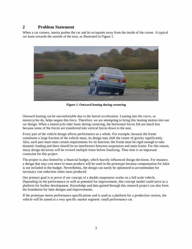
Table of Figures Figure 1. Outward leaning during cornering ............................................................................................. 2
Figure 2. Fall schedule............................................................................................................................. 3
Figure 3. Spring schedule ........................................................................................................................ 3
Figure 4. Wire frame ............................................................................................................................... 5
Figure 5. Solid frame ............................................................................................................................... 5
Figure 6. Primary suspension of EP1798081 ............................................................................................ 6
Figure 7. Suspension linkage variation ..................................................................................................... 7
Figure 8. Primary suspension tie-rod ........................................................................................................ 8
Figure 9. Center of gravity ....................................................................................................................... 8
Figure 10. Center of gravity height response ............................................................................................ 9
Figure 11. Coil spring design ................................................................................................................... 9
Figure 12. Leaf spring design .................................................................................................................. 9
Figure 13. Primary suspension current design .......................................................................................... 2
Figure 14. Primary suspension lower control arm stress analysis .............................................................. 3
Figure 15. Wesll 4 wheel leaning suspension ........................................................................................... 3
Figure 16. Can-Am Spyder ...................................................................................................................... 4
Figure 17. Mercedes Benz F300 Life Jet .................................................................................................. 4
Figure 18. Paralympics Trike ................................................................................................................... 4
Figure 19. Double Wishbone Suspension ................................................................................................. 5
Figure 20. Steering Sensitivity ................................................................................................................. 6
Figure 21. Steering Mechanism ............................................................................................................... 6
Figure 22. Steering Control Gear Rack .................................................................................................... 7
Figure 23. Drivetrain using splined shafts and U-joints ............................................................................ 8
Figure 24. Neutral position ...................................................................................................................... 9
Figure 25. Cornering at 0.4 g ................................................................................................................... 9
Figure 26. Dynamic simulation of assembled model .............................................................................. 10
Figure 27. Income Age Distribution ....................................................................................................... 13

vi
Table of Tables Table 1. Primary suspension spring decision matrix ................................................................................. 2
Table 2. Steering decision matrix ............................................................................................................. 7
Table 3. Testing Parameters ................................................................................................................... 12
Table 4. Similar Vehicles....................................................................................................................... 13
Table 5. Material costs........................................................................................................................... 14
Table 6. Team budget ............................................................................................................................ 14

1
1 Introduction
This document provides material relevant to Team 15’s senior design project, Swayspension.
Calvin College is a four year, liberal arts college in Grand Rapids, Michigan. The Calvin College engineering program offers students degrees in Bachelors of Science in Engineering, with concentrations
in Mechanical, Chemical, Electrical/Computer, and Civil/Environmental. Senior Design is the year-long
capstone course for the engineering program and is intended to provide a real world engineering
experience to the students. During the first semester of this course, teams of students begin the design and feasibility analysis.
1.1 Team Members
Team 15 is comprised of four senior students at Calvin College. All plan to graduate in May 2013 with a B.S.E., Mechanical Engineering concentration.
Meng Chen is an international student from China. He is a competition-driven and motivated engineer,
who has great passion for system design and research activities. He values ambition, diligence and
persistence in his work. Aside from engineering work, he has great interests in economics, astrophysics, psychology, soft management theory, free diving, sensational music, and anything that is fast and furious.
He desires to see and experience many extraordinary sceneries and activities before the age of 35. He
believes having a goal is essential in life and hopes to experience as much of the wonderful world and magnificent nature as possible.
Meng handles all CAD design and computer simulation.
Scott Kamp has been a hands-on enthusiast from a very young age. Starting with Legos and a few simple tools, he has been taking things apart and building small electromechanical projects since his fingers
worked. He really feels that mechanical engineering aligns with his passions. He has spent the past two
summers working in low volume custom manufacturing, and during his junior year he worked in high
volume manufacturing. He is looking forward to joining the workforce and hopefully ending up somewhere exotic, such as Alaska or overseas. In his free time he enjoys camping, woodcarving, satirical
writing, a variety of sports, and learning his guitar.
Scott will lead fabrication in the spring. He currently helps with prototyping and designing.
Nate Konyndyk is currently working part time at Best Metal Products where he has been an intern for
over a year. He has always had an interest in designing cars and is very excited to help design a new
suspension system for a vehicle. Nate enjoys sports, hanging out with friends, camping, fishing, and traveling the world. Upon graduating, Nate plans to work at an engineering company in the Greater Grand
Rapids area.
Nate is in charge of the team finances and coordinating budget decisions.
Jacob VandeHaar has held two internships, one doing academic research and one manufacturing in West Michigan. He enjoys fixing cameras, browsing Wikipedia, and trying to keep his car operable. He also
enjoys traveling, reading, making and viewing art, and various other non-discipline activities. Jacob plans
to find an entry-level engineering job.
Jacob acts as primary designer for the team. He will aid in fabrication in the spring.
2
2 Problem Statement
When a car corners, inertia pushes the car and its occupants away from the inside of the corner. A typical car leans towards the outside of the turn, as illustrated in Figure 1.
Figure 1. Outward leaning during cornering
Outward leaning can be uncomfortable due to the lateral acceleration. Leaning into the curve, as
motorcycles do, helps negate this force. Therefore, we are attempting to bring this leaning motion into our
car design. When a motorcycle rider leans during cornering, the horizontal forces felt are much less because some of the forces are transferred into vertical forces down to the seat.
Every part of the vehicle design affects performance as a whole. For example, because the frame
constitutes a large fraction of the vehicle mass, its design may shift the center of gravity significantly.
Also, each part must meet certain requirements for its function: the frame must be rigid enough to take dynamic loading and there should be no interference between suspension and main frame. For this reason,
many design decisions will be revised multiple times before finalizing. Thus time is an important
constraint for this project.
The project is also limited by a financial budget, which heavily influenced design decisions. For instance,
a design that may cost more to mass produce will be used in the prototype because compensation for labor
is not included in the budget. Nevertheless, the design can easily be optimized to accommodate for necessary cost reduction when mass produced.
Our primary goal is to prove if our concept of a double suspension works on a full scale vehicle.
Depending on the performance as well as potential for improvement, this concept model could serve as a
platform for further development. Knowledge and data gained through this research project can also form the foundation for later designs and improvements.
If the prototype meets performance specifications and is used as a platform for a production version, the
vehicle will be aimed at a very specific market segment: small performance car.

3
3 Task Specifications and Schedule
The fall semester schedule is shown in Figure 2. A more detailed schedule for the spring semester highlighting the fabrication and testing of the design is shown in Figure 3.
Figure 2. Fall schedule
Figure 3. Spring schedule

4
4 Design Norms
Innovation Swayspension is an innovative approach to solving issues associated with
driving. Innovation plays an essential part in our design and product definition,
differentiating our product from our competitors’.
Reliability Reliability is absolutely essential for our engineering design. Our suspension
must be reliable and trustworthy to handle all kinds of driving.
Precision We make the best efforts to ensure the quality and performance of our
suspension. Parts tolerance must be controlled strictly to ensure maximum performance and proper tilting operation.
Transparency Our suspension will provide clear feedback for driver. It will be responsive,
allowing the driver to feel the cornering conditions of the vehicle and make appropriate adjustments as needed.

5
5 Design
5.1 Frame
As the most fundamental part of any vehicle, the frame needs to safely hold all components together.
Initially, the frame was drawn by plotting datum points in a CAD program. The points were connected to form the wire frame shown in Figure 4.
Figure 4. Wire frame
This initial model enabled us to see where everything needed to be attached, and how the layout would
work. The frame could then been idealized. Tubing size and form could quickly be defined for static
Finite Element Analysis (FEA). After optimizing the geometry of the wire frame model, drafts will be published as a reference for constructing a solid model (Figure 5). In the solid model, details regarding
the cutting angle and notch size will be determined for each tube.
Figure 5. Solid frame

6
5.2 Primary Suspension
Our primary suspension is the main component that distinguishes our vehicle from all other designs. It is
what allows and simultaneously causes the vehicle to sway while cornering. It will give our vehicle a high center of gravity, to allow the swaying motion to occur passively. It is also the component with the two
most critical connections—one to the frame and the other to the secondary suspensions.
We found numerous prototypes which use the same chassis and wheel tilting concept. A good example of
this is European Patent EP1798081 (
Figure 6). However, none of the vehicles or patents researched use a passive-leaning linkage.
Figure 6. Primary suspension of EP1798081
The primary-suspension linkage geometry controls the relative angle between the body of the vehicle and
the wheels. The relative angle can be adjusted by changing the length of the vertical linkages. Three
clarifying examples are shown in Figure 7.

7
Figure 7. Suspension linkage variation
One problem for our vehicle that is not an issue for the snowmobile in EP1798081 (Figure 6) is the slight widening of the track (the tire-tire distance for either front or rear wheels) under loading. Lateral tire
movement is deleterious to handling capability, causing under- or over-steer depending on the forces
involved. To stop track widening, a tie-bar was added to hold the two lower control arms fixed relative to each other (Figure 8).

8
Figure 8. Primary suspension tie-rod
In order to lean while cornering, the center of gravity of the vehicle must be low enough relative to the
pivot point of the vehicle (Figure 89).
Figure 9. Center of gravity
The primary suspension linkages are designed to be substantially higher than the wheels so that the
vehicle’s center of gravity hangs below them. When the vehicle corners, the frame shifts away from the apex, thereby forcing the suspension to tilt towards the apex. The necessary linkages were constructed in
CAD to be simulated. Results from a sensitivity study show the height of the center of gravity at various
tilting positions (Figure 10).

9
Figure 10. Center of gravity height response
Because the center of gravity stays within 0.1 mm, a spring is sufficient to control tilting and return the frame to neutral when driving straight. The spring mechanism is adjustable to accommodate varying
driving conditions. Two spring mechanisms were proposed to regulate frame tilting: a coil spring design
(Figure 11) and a leaf spring design (Figure 12).
Figure 11. Coil spring design
Figure 12. Leaf spring design

2
Table 1. Primary suspension spring decision matrix
Design Weight Coil spring
Leaf spring
Cost 8 2 8
Time 6 5 5
Adjustability 9 7 8
Effect on CG 10 1 6
Ease of Fabrication 6 5 5
Total 149 256
The leaf spring design is the best option. The spring rate can be changed by inserting or removing separate layers. The current primary suspension, using a leaf spring, is shown in Figure 13.
Figure 13. Primary suspension current design
FEA analysis was performed on the lower control arm (Figure 14). The analysis indicated that a 500-lb
load would be required to stress a single primary lower control arm to the yield point. The current sprung
mass (including operator) is 650 lbs, distributed over four control arms. Therefore the control arm has a safety factor of 3.

3
Figure 14. Primary suspension lower control arm stress analysis
5.2.1 Research
We found many designs of vehicles that lean into turns through two suspensions. However, what makes our design different is all those designs have an active suspension system, meaning something actuates
the leaning. This actuation is caused from hydraulics, linkages, or the driver leaning his or her body to
one side or the other. In our design, we would use a passive system that requires outside forces to cause the leaning. The outside force we are using is the lateral acceleration caused from inertia when the
steering is to one side of the other. The force of inertia causes the vehicle to want to continue driving
straight and we are going to take advantage of this inertia and sway the vehicle.
One of the many designs we looked at that were similar to our project was the Wesll 4 Wheel Leaning Suspension System (Figure 15).
Figure 15. Wesll 4 wheel leaning suspension
This system is similar to our design except this is an active system. A system of linkages controls the
leaning of the vehicle whereas we use inertia to control our leaning. Another design we looked into was the Can-Am Spyder (Figure 16) and the Mercedes Benz Fascination F300 Life Jet (Figure 17). Once
again, both of these suspension systems are active. The Mercedes Benz F300 Life Jet has an active system
where hydraulic pumps control the leaning of the vehicle as a function of the speed taken around a turn.

4
Figure 16. Can-Am Spyder
Figure 17. Mercedes Benz F300 Life Jet
A fourth concept we discovered that is similar to our project is a trike used in the Paralympics (see Figure
18). This design uses bicycle tires and is similar to our project. The primary issue with this design is that it has three wheels where we would like to use a four-wheel design to better show our double suspension
system.
Figure 18. Paralympics Trike
5.2.2 Challenges
One of the major challenges of the secondary suspension system is the ability to also accommodate a
steering mechanism in the front and a rear drivetrain. The suspension system must be designed around the addition of the steering mechanism in the front by allowing the push/pull rod which connects to the hub
of the wheel which turns the front wheels left or right. The challenge of the rear secondary suspension is
to allow rear axles to connect to each wheel. These axles are powered by an engine which in turn rotates
the wheels ultimately causing the vehicle to move. Despite currently not including a drivetrain in our design, we are still designing individual components of the vehicle to have the option of including a
drivetrain later in the year. With this said, the rear secondary suspension must be designed to include the
possibility of a drivetrain also being connected to the wheel. Due to differing functions of a steering mechanism and the drivetrain, the front and rear secondary suspensions will differ slightly.

5
5.3 Secondary Suspension
The secondary suspension absorbs bumps involved in everyday driving, like the suspension system on
typical vehicles. The reason to have two separate suspension systems is because one suspension cannot do both functions. With both systems, the driver experiences the most comfort, by the smooth ride and the
decreased lateral acceleration. One of the approaches to designing the secondary system is to use a
standard double wishbone design with a shock between each arm, all of which connects to the wheel hub.
An example of the double wishbone design is shown in Figure 19 below.
Figure 19. Double Wishbone Suspension
With this type of suspension, when the wheel hits a bump, the wheel will bounce up or down causing the
spring and the shock to extend or retract, hence absorbing much of the energy of the disturbance.
The front suspension will be designed around the steering mechanism which turns the front wheels left or
right.
The design of this suspension is especially difficult because it must work flawlessly with the upper and lower arms, connecting shocks, and the wheels. Due to differences in weights of drivers and the desire of
performance, the shocks can be adjusted by moving the location of the upper connector for the shock
either further or closer to the wheel. This is done by moving where the pin connector is inserted into the upper arm. There are several pinholes on the upper arm where the shock is attached.
5.4 Steering
Our steering mechanism must be reliable, responsive and user-friendly. Reliable steering control is,
perhaps, the most important safety aspect for a vehicle. Vehicles must be controllable at all times;
therefore, the steering system needs to be designed with redundancy to ensure the linkages and joint integrity during the operation.
Responsiveness aspect of the steering relates to the steering angle sensitivity curve, the rate of wheel
angle changes to the rate of steering wheel angle changes. Ideally, the steering is less sensitive during the

6
first half rotation of the steering wheel and becomes increasingly sensitive as the rotation of the steering
wheel increases like illustrated in Figure 20 below.
Figure 20. Steering Sensitivity
Also, the steering control must be user friendly. The steering wheel response from the vehicle tilting must
be minimized, preferably eliminated completely. So, the wheel steering angle does not change with the
frame tilting.
Challenges for the steering mechanism design are mostly brought by the vehicle tilting motion. The
frame’s relative position to the wheel changes significantly when the vehicle is tilted in a corner. This
means, conventional type of steering mechanism design would not be able provide precise control to the
wheel.
To solve the issue, two solutions were considered. The first solution involves either hydraulic or electrical
actuation. Instead of connected by physical linkages, the vehicle adopts a drive-by-wire type of control.
There are multiple advantages for this system: the sensitivity curve for steering can be easily achieved by programing method, there are a lot more flexibility to fine tune the steering and handling. However, the
major flaw of the system is the reliability. Because the wheel is no longer physically connected to the
steering, the vehicle will become uncontrollable in the case of electronic failure. Also, the cost for adopting such a system is much higher than our alternative proposal, series push-rod design.
Figure 21. Steering Mechanism

7
The alternative design utilizes the parallelism of the primary and secondary suspension and positions the
linkage joints deliberately in-line with the primary and secondary suspension, so that the distance between two joints stays the same regardless the tilting position of the vehicle. This is shown in Figure 21 above.
Hence, the steering wheel angle relative to the frame is the only determining factor for the wheel angle.
Also, the design offers directly linkage between the steering wheel and front wheel of the vehicle, thus,
improve the reliability. The linkage system is easy to fabricate and much less expensive. A series push-rod system was selected using a decision matrix (Table 2).
Table 2. Steering decision matrix
Weight Electronic actuation
Series push-rod
Reliability 10 3 10
Design flexibility 5 8 4
Cost 10 2 7
Fabrication difficulty 5 2 3
Time 10 6 3
Total 160 235
After the design decision was made, a more detailed version of the design has been updated to the series
push-rod mechanism. The steering wheel will control the rotation of a pinion gear, which in turn, shift the gear rack left and right to actuate the push-rod connections. Currently, the 4 inches of shifting range from
the left most position to the right most position is required to achieve desired steering wheel angle. Two
rotations on the steering wheel are required to reach the steering limit. Therefore, the pitch diameter for our pinion gear was determined to be 1 in. Compatible parts were found online, McMaster Carr, which
has pitch diameter of 1” and pitch 24 with the meshing gear rack. A model of the steering control gear
rack is shown in Figure 22.
Figure 22. Steering Control Gear Rack

8
5.5 Drivetrain
After discussing the scale of the project with our industrial consultant, we determined to scale back our
design. To scale back the project, the drivetrain has been deferred at this stage of design. One possible design is illustrated in Figure 23 below.
Figure 23. Drivetrain using splined shafts and U-joints
If the main suspension designs, fabrication and testing were to be accomplished ahead of schedule in
April, then the drivetrain design will be revived and added as an extra feature for our prototype.

9
6 Simulation
The concept of a primary and secondary suspension system was tested through two simplified models, one being a Lego® model and the other an aluminum model which uses rubber bands and a string to
demonstrate the shocks.
Software was used to obtain more accurate system response for our specific design. Mechanism simulation was also conducted in Pro/E to determine the system response to various driving patterns.
Gravity condition in CAD program would easily be manipulated to simulate the vehicle driving straight,
accelerated, decelerate and pass corner as various speeds. For simplification and fluidity of the process,
initial simulation was only performed on a single suspension. The center of gravity of the total assembly was estimated and represented by a force load pointing towards the direction of gravitation.
Figure 24. Neutral position
Figure 25. Cornering at 0.4 g

10
Sensitivity analysis was performed to determine the optimal center of gravity position and the threshold
position to achieve tilting. After obtaining the desired center of gravity range for the top-level assembly, connections between the frame and primary suspension could be determined in more details.
Figure 26. Dynamic simulation of assembled model
The complete vehicle was dynamically simulated to verify the design. Light-weight, complex components
such as the wheels and steering assemblies were excluded from this simulation to improve simulation capability. Several major concerns emerged from the simulation results:
Vehicle demonstrates minimal tilting without adding driver weight to the simulation. This means
our vehicle response might be too reliant on driver weight, physique and some other factor which
we cannot control.
To solve the issue of tilting sensitivity to driver condition, we could shift the center of gravity of
the frame down relative to the suspension. However, this causes clearance issue to the ground and
bigger wheels will be needed to compensate the clearance loss. Nevertheless, engine or battery
weight was not considered in this simulation either. If placed properly, it would shift the center of
gravity down significantly.
Current conditions suggest that there might be a lateral-acceleration tilting activation threshold.
At 0.4-g lateral acceleration without a driver, the tilting was small. However, at 0.7-g lateral
acceleration the system achieved significant tilting.

11
7 Integration, Testing, and Debugging
One of the main goals of the project is to reduce the lateral acceleration the driver experiences while the vehicle is cornering. Modern accelerometers, especially when paired with the power of smartphones, are
very capable and adaptable tools. We have already found an app that records acceleration data in all three
dimensions. We plan to mount the smartphone to a fixed part within the frame as we are testing it, in order to take data while the car is moving. This data will be able to tell us if our objectives have been
met.
We have two methods by which we plan to test the vehicle while it is moving, and because a drivetrain is
beyond the scope of our project, we have determined alternate methods. The first will be with gravity, as we plan to drive it repeatedly down the hill on the east side of campus. The second is to pull the vehicle
with a golf cart, at a constant speed, going around a fixed course. This will enable us to keep the testing
repeatable.
The dynamic response of the frame at rest will be relatively simple. We will place the vehicle on a level
surface, and with two people, manually tilting the frame. When the individuals holding the frame let go, it should return very close to the upright position, and in a relatively short time.
The individual components and subsystems will also be tested individually. A brief description and the
goals are shown below in Table 3.

12
Table 3. Testing Parameters
Test Testing Order
Testing Subjects
Testing Goals Testing Purposes
Frame Static
Loading Test
1 Frame Frame can take 650 lbs static
Load
Ensure overall rigidity of the
frame
Leaf Spring
Strain Test
2 Primary Susp.
Leaf Spring
Leaf Spring can reach
required strain without
deform permanently
Verify the performance of
leaf spring design
Suspension
Settle Test
3 Secondary
Suspension
There are at least 3 inch of
travel left in the spring
Check the amount of spring
settle on the secondary
suspension Stationary
Steering Test
4 Steering
Assembly
Can control the wheel angle
from Steering wheel
Test the steering response and
functionality
Rolling Test 5 whole vehicle Vehicle can roll forward
straight without controlled
from Steering Wheel
The connection between
suspension and wheel
Braking Test 6 Braking
Assembly
Vehicle should be stopped
from 25 mph to stop in 30 ft at most without skidding
Determine the appropriate
braking force to stop fast while avoid skidding
Dynamic
Steering Test
7 Steering
Assembly
The effect of frame tilting
should have minimum effect
on steering angle
Verify the reduced
countersteering induced by
frame tilting
Cornering
stability
8 whole vehicle Vehicle should remain stable
in a corner
Test the stability of the
leaning angle in a corner
Transient
Response
9 whole vehicle Vehicle retains its leaning
characteristic in a figure-8 driving test
Test the time for the frame to
settle in to positions
Lateral
Acceleration Reduction
10 whole vehicle Measured the maximum
lateral acceleration reduction should be no less than 20%
Test the maximum lateral
acceleration reduction

13
8 Business Plan
8.1 Marketing Study
8.1.1 Competition
Similar sport vehicles with tilting suspensions were researched (Table 4). However, none of the vehicles found have passive leaning, a defining feature of Swayspension.
Table 4. Similar Vehicles
Make Model Wheel Layout
Leaning Method
Status Price
Mercedes-Benz F300 Life Jet Tadpole Active Concept Only
Carver Europe Carver One Trike Active Bankrupt € 30,000
GM Lean Machine Trike Active Concept Only N/A
8.1.2 Market Survey
Following demographical income graph illustrate the earning power of the 21 to 35 year-old age group.
This graph is shown in Figure 27.
Figure 27. Income Age Distribution
This particular group is less likely to be married compared with the age group of 35 to 40 and 45 to 54, while still having significant earning power. Our target market is likely to spend more income pursuing
excitement and new experience. This desire could be satisfied by our Swayspension. Market related to
sports car and track days is relative small and privileged. However, it is equally lucrative and rewarding if a company becomes successful.

14
8.2 Cost Estimate
8.2.1 Development
The materials cost is shown in Table 5.
Table 5. Material costs
Parts Prototype Cost
($)
Steel tubing for frame (70 ft) 154
Bicycle wheels (4) 160
Suspension tube/rod 0
Steering ball joints (2) 20
Suspension ball joints (4) 60
Miscellaneous Steel 0
Steering Wheel 0
Steering Column 80
U-joints (8) 160
Brakes (4) 120
Pedals - gas/brake/clutch 15
Driver Seat 25
Brake/throttle cable (15ft) 15
Drive Train 0
Differential 0
dash/display/controls 10
Seat belt 0
Paint 30
20% Contingency 170
Total 1019
The total budget includes spare parts (as 20%) of the materials cost. No specialty software or tools need to
be purchased. The total budget is then $1,151 (Table 6).
Table 6. Team budget
Item Cost ($)
Prototype materials 1,019
Software 0
Tools 0
Spare parts 102
Printing costs 30
Testing parts 0
Total 1,151

15
9 Conclusion
Current feasibility study indicates that the tilting action is highly sensitive to weight distribution. It will be important and challenging to design the vehicle such that all components coordinate to produce the
desired tilting effect.
Our design appears feasible but will require next semester to build and test the design. The final design report will address the testing results acquired if the design works.

16
10 Acknowledgments
Team 15 appreciates the aid offered by
Ned Nielsen (Team Advisor)
Ren Tubergen (Industrial Consultant)
Phil Jasperse (Shop Manager)

17
11 References
http://www.Alan927.com
http://www.jumpjet.info/Classic-Games/Windows/RCT/Facilities/Coasters/Suspended/Suspended.html
http://wendolonia.com/bm/hammock_car.jpg
http://thekneeslider.com/archives/2009/01/29/wesll-4-wheel-leaning-suspension-system/
http://motorcyclesspecification.blogspot.com/2012/04/2012-can-am-spyder-rt-s-review.html
http://www.cyclingnews.com/features/photos/sea-otter-2012-danny-hart-jared-graves-and-tara-llanes-race-bikes/220104